

Fujitsu MB95100 Series, F2MC-8FX Series, MB2146-09, MB95FV100-101, MB95FV100-103 Application Note
...Page 1

Fujitsu Microelectronics Europe
Application Note
F²MC-8FX FAMILY
8-BIT MICROCONTROLLER
MCU-AN-395002-E-V10
MB95100 SERIES
EMULATOR HW SETUP
APPLICATION NOTE
Page 2

MB2146-09 – Installation Guide
Revision History
Revision History
Date Issue
2004-10-12 V1.0; M. Vogel
This document contains 23 pages.
MCU-AN-395002-E-V10 - 2 - © Fujitsu Microelectronics Europe GmbH
Page 3

MB2146-09 – Installation Guide
Warranty and Disclaimer
Warranty and Disclaimer
To the maximum extent permitted by applicable law, Fujitsu Microelectronics Europe GmbH restricts
its warranties and its liability for all products delivered free of charge (eg. software include or
header files, application examples, target boards, evaluation boards, engineering samples of IC’s
etc.), its performance and any consequential damages, on the use of the Product in accordance with
(i) the terms of the License Agreement and the Sale and Purchase Agreement under which
agreements the Product has been delivered, (ii) the technical descriptions and (iii) all accompanying
written materials. In addition, to the maximum extent permitted by applicable law, Fujitsu
icroelectronics Europe GmbH disclaims all warranties and liabilities for the performance of the
M
Product and any consequential damages in cases of unauthorised decompiling and/or reverse
engineering and/or disassembling. Note, all these products are intended and must only be used
in an evaluation laboratory environment.
1. Fujitsu Microelectronics Europe GmbH warrants that the Product will perform substantially in
accordance with the accompanying written materials for a period of 90 days form the date of
receipt by the customer. Concerning the hardware components of the Product, Fujitsu
Microelectronics Europe GmbH warrants that the Product will be free from defects in material
and workmanship under use and service as specified in the accompanying written materials
for a duration of 1 year from the date of receipt by the customer.
2. Should a Product turn out to be defect, Fujitsu Microelectronics Europe GmbH´s entire liability
and the customer´s exclusive remedy shall be, at Fujitsu Microelectronics Europe GmbH´s
sole discretion, either return of the purchase price and the license fee, or replacement of the
Product or parts thereof, if the Product is returned to Fujitsu Microelectronics Europe GmbH in
original packing and without further defects resulting from the customer´s use or the transport.
However, this warranty is excluded if the defect has resulted from an accident not attributable
to Fujitsu Microelectronics Europe GmbH, or abuse or misapplication attributable to the
customer or any other third party not relating to Fujitsu Microelectronics Europe GmbH.
3. To the maximum extent permitted by applicable law Fujitsu Microelectronics Europe GmbH
disclaims all other warranties, whether expressed or implied, in particular, but not limited to,
warranties of merchantability and fitness for a particular purpose for which the Product is not
designated.
4. To the maximum extent permitted by applicable law, Fujitsu Microelectronics Europe GmbH´s
and its suppliers´ liability is restricted to intention and gross negligence.
NO LIABILITY FOR CONSEQUENTIAL DAMAGES
To the maximum extent permitted by applicable law, in no event shall Fujitsu
Microelectronics Europe GmbH and its suppliers be liable for any damages whatsoever
(including but without limitation, consequential and/or indirect damages for personal
injury, assets of substantial value, loss of profits, interruption of business operation,
loss of information, or any other monetary or pecuniary loss) arising from the use of
the Product.
Should one of the above stipulations be or become invalid and/or unenforceable, the remaining
stipulations shall stay in full effect
© Fujitsu Microelectronics Europe GmbH - 3 - MCU-AN-395002-E-V10
Page 4

MB2146-09 – Installation Guide
Contents
Contents
REVISION HISTORY ................................................................................................. 2
WARRANTY AND DISCLAIMER .............................................................................. 3
CONTENTS ............................................................................................................... 4
1 INTRODUCTION ................................................................................................... 5
2 HARDWARE REQUIREMENTS............................................................................ 6
2.1 Devices.......................................................................................................... 6
3 SETTING UP THE EMULATION SYSTEM ........................................................... 7
3.1 System Configuration .................................................................................... 7
3.2 BGM Adapter................................................................................................. 8
3.2.1 Connection to the Host Machine ................................................... 8
3.2.2 Connection to the User System..................................................... 8
3.2.3 Adapter Interface Specifications ................................................... 9
3.2.4 Tool Reset Specifications .............................................................. 9
3.3 MCU Board.................................................................................................. 10
3.3.1 Connecting the MCU board to the Evaluation board ................. 10
3.3.2 Jumper settings and switches on MCU board ........................... 11
3.3.3 How to mount oscillator on MCU board...................................... 12
3.4 Evaluation board.......................................................................................... 13
3.4.1 Jumper settings on Evaluation board ......................................... 13
4 SETTING UP THE EMULATION SOFTWARE.................................................... 14
4.1 Download Monitor Program......................................................................... 14
4.2 Making Setup File by Setup Wizard for Emulator ........................................ 14
4.2.1 Procedure for Setting Setup File by Setup Wizard .................... 14
4.2.2 Optimization of response speed during debugging .................. 19
4.3 Executing Program...................................................................................... 20
4.3.1 Run Program ................................................................................. 20
4.3.2 Setting Breakpoints ...................................................................... 21
4.3.3 Types of breakpoints and how to set.......................................... 22
4.3.4 Trace Windows.............................................................................. 22
4.3.5 Display format for trace data ....................................................... 23
4.3.6 Saving setup file for the Emulator............................................... 23
MCU-AN-395002-E-V10 - 4 - © Fujitsu Microelectronics Europe GmbH
Page 5

MB2146-09 – Installation Guide
Chapter 1 Introduction
1 Introduction
This installation guide will help you setting up the MB2146-09 BGM ADAPTER with
the MB2146-301 or MB2146-303 MCU Board for Fujitsu 8FX-microcontroller and its
usage with 8bit-Softune Workbench V30L29 or higher.
© Fujitsu Microelectronics Europe GmbH - 5 - MCU-AN-395002-E-V10
Page 6

MB2146-09 – Installation Guide
Chapter 2 Hardware Requirements
2 Hardware Requirements
DEBUGGING TOOLS
2.1 Devices
This section describes the procedure for actual machine verification using the
emulator. The equipment used for explanation of the emulator is listed below:
• MB2146-09 : BGM Adapter
• MB2146-301 : MCU board with MB95V100-101 (3V version)
• MB2146-303 : MCU board with MB95V100-103 (5V version)
• MB95FV100-101 : 3V evaluation chip
• MB95FV100-103 : 5V evaluation chip
• MB2146-401 : Evaluation board
• Crystal oscillator : 4 MHz
• Power supply for MB2146-401 : 5 VDC
• USB(A-B) cable : USB V1.1
Warning:
Do only supply 5 volts DC to MB2146-401 evaluation board. Power supply is
directly connected to MCU board if jumper settings (JP3 & JP4) on evaluation
board are set to 5V. Higher voltage may damage MCU board, Evaluation board
and BGM adapter!
MCU-AN-395002-E-V10 - 6 - © Fujitsu Microelectronics Europe GmbH
Page 7
MB2146-09 – Installation Guide
PC
E
valuation board
Chapter 3 Setting up the Emulation System
3 Setting up the Emulation System
HARDWARE INSTALLATION
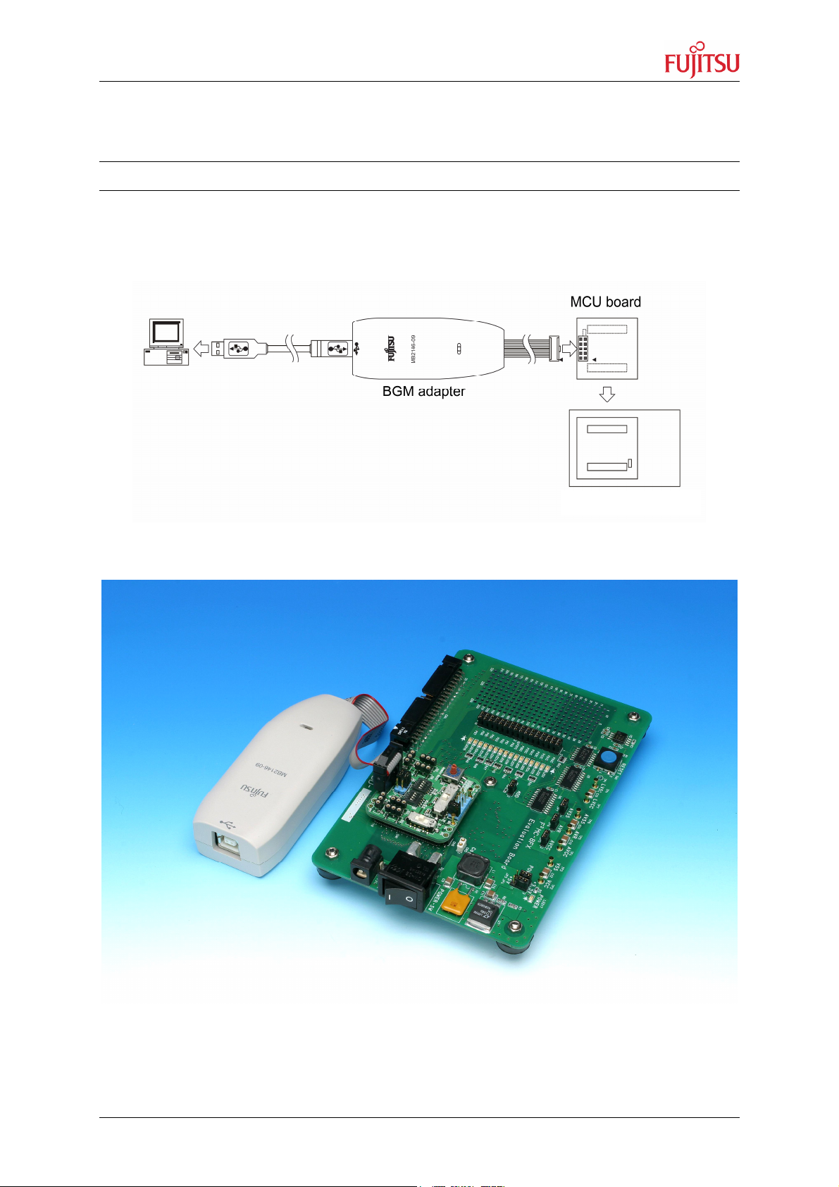
3.1 System Configuration
Connect the adapter between the host machine and the user system so that the
adapter can serve as an emulator under control of the host machine.
Figure 1: System Configuration
Figure 2: Configuration overview
© Fujitsu Microelectronics Europe GmbH - 7 - MCU-AN-395002-E-V10
Page 8

MB2146-09 – Installation Guide
Chapter 3 Setting up the Emulation System
3.2 BGM Adapter
For details, refer the following manual:
• BGM Adapter MB2146-09 Operation Manual
3.2.1 Connection to the Host Machine
Connect the adapter to the host machine using the USB cable.
Figure 3: Connecting the USB Cable
If the BGM adapter is connected the first time to the host machine, it is possible the
operation system searches for a valid device driver. This driver can be found in your
Softune installation directory in subfolder [Drivers], for example “C:\Softune\Drivers\
SiUSBdB.inf”.
3.2.2 Connection to the User System
Connect the adapter to the user system. Plug the user interface connector of the
adapter into the adapter interface connector on the user system.
When plugging the user interface connector, align its index mark (pin no. 1) with the
adapter interface connector's counterpart.
Figure 4: Connection to the User System
MCU-AN-395002-E-V10 - 8 - © Fujitsu Microelectronics Europe GmbH
Page 9

MB2146-09 – Installation Guide
Chapter 3 Setting up the Emulation System
3.2.3 Adapter Interface Specifications
Table 1 shows a pin out of the adapter interface connector mounted on the user
system. Figure 5 shows the connector pins.
Table 1: Adapter Interface Connector Pin out
Connector
pin No.
1 VCC
2 GND
3 BRSTX
4 BDBMX
5 BSOUT
6 BEXCK
7 BSIN
8 N.C
9 GND
10 N.C
*: “BGMA” in the “Input/output” column in the table indicates the BGM adapter.
Connector
pin name
Input/output Remarks
BGMA MCU
BGMA MCU
BGMA MCU
BGMA MCU
BGMA MCU
BGMA MCU
Connected to the MCU's Vcc pin.
Connected to the MCU's Vss pin.
Connected to the MCU's RSTX pin.
Connected to the MCU's MOD pin.
Connected to the MCU's UO0 pin.
Connected to the MCU's UCK0 pin.
Connected to the MCU's UI0 pin.
Not connected
Connected to the MCU's Vss pin.
Not connected
Figure 5: Adapter Interface Connector Pins
3.2.4 Tool Reset Specifications
A tool reset is a hardware reset by the adapter to reset the entire system of the
microcontroller (including the BDSU module) on the user system. When both the
adapter power and microcontroller's user power are turned on, the tool reset is
canceled automatically to enable the microcontroller to be evaluated. The following
shows how to generate a tool reset and how long it remains in effect.
Tool reset generation methods and reset "L" pulse width:
1. Set the micorocontroller’s user power from OFF to ON (power-on reset). The
reset remains in effect for about 16 to 70 ms after the microcontroller’s user
power is supplied.
© Fujitsu Microelectronics Europe GmbH - 9 - MCU-AN-395002-E-V10
Page 10

MB2146-09 – Installation Guide
Evaluation board
MCU board
Chapter 3 Setting up the Emulation System
2. Set the adapter power from OFF to ON (by unplugging and plugging the USB
cable). The reset remains in effect for about 32 to 140 ms after the adapter
power is supplied again.
If the user system and adapter cause an uncontrollable error and the system cannot
be recovered by tool reset generation method 1.), execute tool reset generation
method 2.).
3.3 MCU Board
For details, refer the following manuals:
• MB2146-301 Operation Manual
• MB2146-303 Operation Manual
3.3.1 Connecting the MCU board to the Evaluation board
Align the MCU board and evaluation board facing each other, then plug their mating
connectors together. The connectors are provided with incorrect insertion prevention
keys located diagonally. Position the boards correctly without letting the incorrect
insertion prevention keys interfere with each other and plug connectors together
completely.
Figure 6: Connection of MCU board and Evaluation board
MCU-AN-395002-E-V10 - 10 - © Fujitsu Microelectronics Europe GmbH
Page 11

MB2146-09 – Installation Guide
Chapter 3 Setting up the Emulation System
3.3.2 Jumper settings and switches on MCU board
Please set the following switches and jumpers on the MCU board
1. Set the clock selector switch (SW1-1) to OFF.
2. Set the clock supervisor selector switch (SW1-2) to OFF.
3. Set the APB8 bus output selector switch (SW1-3) to OFF.
4. Set the C-pin selector switch (SW1-4) to OFF.
5. Set the clock input selector switch (SW2) to OFF.
6. Set the product selector switch (SW3) according to table 2.
(set to 0: 100-pin package type for evaluation chip)
7. Set the LVD selector switch (SW4) to OFF (middle).
8. Set the power supply selector switch (SW5) to 3V or 5V.
9. Set the jumper plug S2 to LVD0 (right).
10. Set the jumper plug S1 (1+2) to CB.
11. Mount the main clock oscillator (refer chapter 3.3.3)
12. Mount the sub clock oscillator (refer chapter 3.3.3, not required)
9
6
1-4
8
7
5
11
12
10
Figure 7: switch and jumper setting on MCU board
© Fujitsu Microelectronics Europe GmbH - 11 - MCU-AN-395002-E-V10
Page 12

MB2146-09 – Installation Guide
Chapter 3 Setting up the Emulation System
Table 2: Setting of product selector switch
3.3.3 How to mount oscillator on MCU board
Plug crystal oscillator or ceramic resonator into the crystal oscillator mounting
sockets (for the main clock and sub clock) on the MCU board. The MCU board has
one crystal oscillator mounting socket for the main clock (SC1-SC3) and another for
the sub clock (SC4-SC6). To distinguish them from each other, the board has the
“MAIN CLOCK” and “SUB CLOCK” labels printed near the main-clock socket and
sub clock socket, respectively. Mount the crystal oscillator along with two capacitors
on the MCU board. By use of a ceramic resonator these capacitors are nit required.
Capacitor mounting socket* Capacitor mounting socket*
Crystal oscillator mounting socket
Ceramic
resonator
Crystal
oscillator
*Capacitors are not required if a
ceramic resonator is used!
Figure 8: Crystal or ceramic oscillator mounting
MCU-AN-395002-E-V10 - 12 - © Fujitsu Microelectronics Europe GmbH
Page 13

MB2146-09 – Installation Guide
Supply only
Chapter 3 Setting up the Emulation System
3.4 Evaluation board
3.4.1 Jumper settings on Evaluation board
Please set jumper plugs on Evaluation board according to following:
1. Set jumper plugs JP3 and JP4 to the right supply voltage,
depending on your evaluation MCU and MCU board
(1-2: 5V, 2-3: 3.3V)
2. Set analogue power supply jumper plug JP5
(AVCC pin is connected to VCC of evaluation board)
3. Set analogue reference input jumper plug JP6
(AVR pin is connected to VCC of evaluation board)
4. Set analogue power supply (GND) jumper plug JP7
(AVSS pin is connected to VSS of evaluation board)
5. Set operation mode jumper plug JP8
(MOD pin connected to GND -> run mode)
6. Set LED jumper plugs JP1 and JP2 to connect I/O port to LEDs on evaluation
board
4
3
12
56
Figure 9: jumper settings on evaluation board
5V DC!
© Fujitsu Microelectronics Europe GmbH - 13 - MCU-AN-395002-E-V10
Page 14

MB2146-09 – Installation Guide
Chapter 4 Setting up the Emulation Software
4 Setting up the Emulation Software
SOFTWARE SETTINGS
For the following steps a Softune 8FX/8L version later than V30L29 is needed.
4.1 Download Monitor Program
Using the Emulator Debugger requires downloading a monitor program to the ICE
(In-Circuit Emulator) according to the chip to be used. The ICE checks the type and
version of the monitor program at start of debugging and loads the monitor program
automatically.
Figure 10: automatic download of monitor program
This sample gives an example of the connection between the ICE (MB2146-09) and
personal computer via USB.
For details, refer to the following manual:
• Softune 8FX/8L First Step Guide
4.2 Making Setup File by Setup Wizard for Emulator
4.2.1 Procedure for Setting Setup File by Setup Wizard
This section explains the procedure for making an additional setup file for the
emulator.
1. Right click on ‘Debug’ in project-window and choose [Add Setup] -> [New…].
MCU-AN-395002-E-V10 - 14 - © Fujitsu Microelectronics Europe GmbH
Page 15

MB2146-09 – Installation Guide
Chapter 4 Setting up the Emulation Software
2. Enter a name for the new setup file and click [OK].
3. Follow the steps in the upcoming setup wizard. Click [Next] to go to the next
window.
4. Select ‘Emulator Debugger’ as Debug Type.
© Fujitsu Microelectronics Europe GmbH - 15 - MCU-AN-395002-E-V10
Page 16

MB2146-09 – Installation Guide
Chapter 4 Setting up the Emulation Software
5. Select ‘MB2146-09’ as ICE type.
6. Choose ‘USB’ for Device Name.
7. Enter oscillator frequency in MHz. (In this case 4MHz)
MCU-AN-395002-E-V10 - 16 - © Fujitsu Microelectronics Europe GmbH
Page 17

MB2146-09 – Installation Guide
Chapter 4 Setting up the Emulation Software
8. Here a batch file to be executed directly after start of debugger can be specified.
(not needed in this case)
9. Activate ‘Auto load when starting debug’ option by checking the box. Here a
batch file executed before or after load can be specified (not in this case).
10. Choose ‘Select All’ under Select setting item.
© Fujitsu Microelectronics Europe GmbH - 17 - MCU-AN-395002-E-V10
Page 18

MB2146-09 – Installation Guide
Chapter 4 Setting up the Emulation Software
11. Click [Finish] to end the setup wizard and to complete setup.
12. The added setup file appears in the ‘project’-window. The setup file, which starts
up when the [Start debug] command in the [Debug] menu is executed, is
displayed in blue. Double-clicking the setup file, the Debugger starts up according
to its setup information.
MCU-AN-395002-E-V10 - 18 - © Fujitsu Microelectronics Europe GmbH
Page 19

MB2146-09 – Installation Guide
Chapter 4 Setting up the Emulation Software
4.2.2 Optimization of response speed during debugging
The communication speed of user system and MB2146-09 change by the operating
frequency of the target microcontroller. When the operating frequency is reduced,
especially in the sub clock mode, communication speed is also reduced. In this case,
optimize the communication speed. The function increasing the operating frequency
automatically is called clock-up mode. The default is ON at that time.
Also, this setting is performed at the setup wizard or [Setup] -> [Debug Environment]
-> [Debug Environment…] -> [Response speed] tab.
Note:
When the clock-up mode is used, the operating frequency is changed automatically
at breaking. If the failure is caused by changing the operating frequency, disable the
clock-up mode.
If a break occurs immediately after changing the system clock mode by the user
program, no clock up is performed during oscillations stabilization wait state. Clock
up will be performed when oscillations are stabilized.
© Fujitsu Microelectronics Europe GmbH - 19 - MCU-AN-395002-E-V10
Page 20

MB2146-09 – Installation Guide
Chapter 4 Setting up the Emulation Software
4.3 Executing Program
4.3.1 Run Program
1. Turn on the user power to the MB2146-401.
2. The MB2146-09 POWER LED turns orange.
3. Double-click emulator_usb.sup (or however you named setup file before) in the
debug folder in the project window to start the emulator debugger.
4. Reset MCU before executing the program.
5. Run your user program.
6. To stop user program click the marked button.
MCU-AN-395002-E-V10 - 20 - © Fujitsu Microelectronics Europe GmbH
Page 21

MB2146-09 – Installation Guide
Chapter 4 Setting up the Emulation Software
4.3.2 Setting Breakpoints
While the Debugger executes a program, the execution of the program can be
stopped when the program counter (PC) passes a certain address or accesses data
at a certain address.
The position where the execution of the program is stopped is called a breakpoint.
The user can set the code breakpoints, data monitoring breakpoints and sequence
breakpoints.
Click the left circle of the source window to set the breakpoint “X”.
The yellow line indicates the current position of the instruction pointer (IP).
Note: The IP value is the same as the PC value.
© Fujitsu Microelectronics Europe GmbH - 21 - MCU-AN-395002-E-V10
Page 22

MB2146-09 – Installation Guide
Chapter 4 Setting up the Emulation Software
4.3.3 Types of breakpoints and how to set
There are three types of breakpoint as follows:
Select [Breakpoint] from the [Debug] menu to open the [Break] dialog.
This dialog can also set breakpoints. It also provides a list of set breakpoints.
• Code breakpoint
Code breakpoint is a breakpoint to stop the program when the PC attempts to
execute a set address. For both Simulator and Emulator, the PC stop position
is a breakpoint before execution. Up to 256 code breakpoints can be set.
• Data breakpoint
Data breakpoint is a breakpoint to stop program when the PC accesses data
at a set address. Read, write, and read/write can be set as access conditions.
Up to two data breakpoints can be set.
• Sequence breakpoint
This breakpoint stops the program being executed when the program is
executed at two specified addresses from “Level 1” to “Level 2.”
4.3.4 Trace Windows
When the trace function is enabled, data is always sampled and stored in the trace
buffer during execution.
Trace information to be actually displayed is that on the 16 branches immediately
preceding suspension of execution.
The trace buffer is structually a ring-shaped, so data is overwritten automatically
from the beginning of the sequence buffer when the trace buffer is full.
1. Select [Trace] from the [View] menu to open the trace window.
MCU-AN-395002-E-V10 - 22 - © Fujitsu Microelectronics Europe GmbH
Page 23

MB2146-09 – Installation Guide
Chapter 4 Setting up the Emulation Software
2. The program is executed and stopped. Right-click the trace window to select
[Refresh] from the shortcut menu. The trace result appears.
4.3.5 Display format for trace data
There are two display formats for trace data:
• Display in order of instruction execution (Instruction)
• Display in source lines (Source)
Use the shortcut menu to switch between the display format for trace data. No trace
stamp is displayed.
4.3.6 Saving setup file for the Emulator
A setup file is not saved automatically until debugging is terminated. When updated,
save the setup file.
Select the [Save...] command from the [File] menu to save the setup file for the
emulator in the Save dialog.
The setup file can be saved only in debug mode.
© Fujitsu Microelectronics Europe GmbH - 23 - MCU-AN-395002-E-V10
 Loading...