

Fujitsu MAU3147RC SERIES, MAV2073RC SERIES, MAU3073RC SERIES, MAV2036RC SERIES, MAU3036RC SERIES Technical Manual
Page 1

C141-C009-01EN
MAU3036RC, MAU3073RC, MAU3147RC SERIES
MAV2036RC, MAV2073RC SERIES
DISK DRIVES
SERIAL ATTACHED SCSI INTERFACE
SPECIFICATIONS
Page 2

FOR SAFE OPERATION
Handling of This Ma nual
This manual contains important information for using this product. Read thoroughly before using
the product. Use this product only after thoroughly reading and understanding especially the
section "Important Alert Items" in this manual. Keep this manual handy, and keep it carefully.
FUJITSU makes every effort to prevent users and bystanders from being injured or from suffering
damage to their property. Us e th e product according t o t hi s m anual .
This product is designed and manufactured for use in standard applications such as office work,
personal devices and household appliances. This product is not intended for special uses (atomic
controls , aeronautic o r s p ace s y s t em s , mass tran s p or t v ehicle operatin g co n t ro l s , medical dev i ces
for life support, or weapons firing controls) where particularly high reliability requirements exist,
where the pertinent levels of safety are not guaranteed, or where a failure or operational error could
threaten a life or cause a physical injury (hereafter referred to as "mission-critical" use). Customers
considering the use of these products for mission-critical applications must have safety-assurance
measures in p l ace b efo rehan d . Moreover, they are request ed to consul t o ur s ales representat i v e
before embarkin g o n s uch s p eci al ized use.
First Edition March 2005
The contents of this manual may be revised without prior notice.
The contents of this manual shall not be disclosed in any way or reproduced in any media without
All Rights Reserved, Copyright FUJITSU LIMITED 2005
C141-C009
the express written permission of Fujitsu Limited.
Page 3

Revision History
(1/1)
Edition Date
01 2005.02.20 — —
Revised section (*1)
(Added/Deleted/Altered)
Details
*1 Section(s) with asterisk (*) refer to the previous edition when those were deleted.
C141-C009
Page 4

This page is intentionally left blank.
Page 5

Preface
This manual explains concerning the 3.5 inch hard disk drives with internal Serial
Attached SCSI (SAS) controller.
The purpose of this manual is to provide the specifications and functions of SAS
for use of these magnetic disk drives incorporated into user systems, and to present
the information necessary for creating host system software. This manual is
written for users who have a basic knowledge of hard disk drives and their use in
computer systems.
The composition of manuals related to these disk drives and the range of subjects
covered in this manual are shown in “Manual Organization,” provided on a
subsequent page. Please use these other manuals along with this manual as
necessary.
The organization of this manual, related reference manual and conventions for
alert messages follow.
Overview of Manual
This manual consists of the following six chapters, glossary, abbreviation, and
index:
Chapter 1 SAS Interface
This chapter describes the topology, physical and electrical requirements, interface
protocol, and other operations of the interface.
Chapter 2 Command Processing
This chapter describes the basic logical specifications related to command
processing.
Chapter 3 Data Buffer Management
This chapter describes the data buffer configuration, data transfer processing
functions and cache operations.
Chapter 4 Command Specifications
This chapter describes detailed command specifications and how to use them.
C141-C009 i
Page 6

Preface
Chapter 5 Sense Data and Error Recovery Methods
This chapter describes the configuration and contents of sense data which report to
the host s y s t em wh en an erro r o ccurs , etc., k ey i nfo rm at ion necessary for erro r
recovery, recommended procedures for error recovery to be executed through host
system software and retry processing.
Chapter 6 Disk Media Management
This chapter describes the procedure for initializing the disk media, methods of
treating media defects and data recovery methods.
Glossary
The gloss ary exp l ai n s t ech n i cal t erm s wh i ch are n eces s ary t o t h e read er’s
understanding when reading this manual.
Acronyms and Abbreviations
This list shows the full spelling of abbreviations used in this manual.
Index
ii C141-C009
Page 7

Preface
CONVENTIONS USED IN THIS MANUAL
The model names of the disk drives covered by this manual differ depending
on their device types and capacity (*1). In addition, these disk drives are called
Intelligent Disk Drive (IDD), "drive" or "device" in this manual.
Note: Model Name
M AU 3 147 RC
Interface type
Formatted capacity (1,000MB units)
* 1MB=1,000,000bytes
Disk size 3: 3.5 inch
2: 2.5 inch
Type AU: 3.5 inch height, 15,000rpm
AT: 3.5 inch height, 10,025rpm
AV: 2.5 inch height, 10,025rpm
Decimal numbers are represented normally.
Hexadecimal numbers are represented as shown in the following examples:
X’17B9’, 17B9h, 17B9H, or 17B9H.
Binary number is represented as "010", 010b.
An X is used to represent mode parameters that are ignored by the MODE
SELECT and MODE SELECT EXTENDED commands. An X is also used
to represent mode parameters reported by the MODE SELECT and MODE
SELECT EXTENDED commands and that vary depending on conditions at
the time.
C141-C009 iii
Page 8
Preface
Conventions for Alert Messages
This manual uses the following conventions to show the alert messages. An alert
message con s i s t s o f an al ert signal and al ert s tatements . The alert si g n al co n s i s t s o f
an alert symbol and a signal word or just a signal word.
The followi n g are t h e al ert s i g n al s an d t h ei r meanings:
This indicates a hazardous s i tu at ion likely to result in
serious personal injury if the user does not perform
the procedur e correctly.
This indicates a hazardous s i tu at ion could result in
serious personal injury if the user does not perform
the procedur e correctly.
This indicates a hazardous s i tu at ion could result in
minor or moderate personal injury if the user does
not perform t h e p ro ced ur e correct ly. This al ert signal
also indicates that damages to the product or other
property, may occur if the user does not perform the
product correctly.
Attention
This indicates information that could help the user
use the product more efficiently.
In the text, the alert signal is centered, followed below by the indented message. A
wider line s p ace preced es an d fol lows the alert m es s ag e t o s ho w wh ere t h e al ert
message begins and ends. The following is an example:
(Example)
It is possible to use bit 7 and bit 6 of the control byte as an inherent
control field in future product specifications. It is recommended that
the INIT specify zero i n this field .
Please forward any comments you may have regarding this manual.
To make this manual easier for users to understand, opinions from readers are
needed. Please write your opinions or requests on the Comment at the back of this
manual and forward it to the address described in the sheet.
iv C141-C009
Page 9

Preface
MANUAL ORGANIZATION
Product Manual
1. Outline
2. Specifications
3. Data Format
4. Installation Conditions
5. Installation Procedure
6. Diagnosis and Maintenance
Interface Specifications
(This Manual)
1. Serial Attached SCSI (SAS) Interface
2. Command Processing
3. Data Buffer Management
4. Command Specifications
5. Sense Data and Error Recovery Methods
6. Disk Media Management
Maintenance Manual 1. Specifications and Equipment Configuration
2. Maintenance and Diagnosis
3. Troubleshooting
4. Removal and Replacement Procedures
5. Operating Theory
C141-C009 v
Page 10

Preface
REFERENCED STANDARDS
The product specifications and functions described in this manual conform to the
following standards:
Specification
(document) number
T10/1562-D
Revision 05
T10/1601-D
Revision 07
T10/1236D
Revision 20
T10/996D
Revision 8C
T10/1157D
Revision 24
T10/1561
Revision 13
Name
Serial Attached SCSI (SAS) American national
Serial Attached SCSI-1.1 (SAS-1.1) American national
Information technology SCSI Primary
Commands-2 (SPC-2)
Information Technology SCSI-3 Block
Commands (SBC)
Information technology SCSI-3 Architecture
Model (SAM-2)
Information technology SCSI-3 Architecture
Model (SAM-3)
Concerned
organization
Standards Institute
(ANSI)
Standards Institute
(ANSI)
American national
Standards Institute
(ANSI)
American national
Standards Institute
(ANSI)
American national
Standards Institute
(ANSI)
American national
Standards Institute
(ANSI)
vi C141-C009
Page 11

Contents
CHAPTER 1 SAS Interface............................................................................1-1
1.1 Topologies in SAS Interface ....................................................................1-2
1.1.1 SAS Layering ......................................................................................1-3
1.1.2 Physical links and phys .......................................................................1-4
1.1.3 Ports (narrow ports and wide ports) ....................................................1-4
1.1.4 SAS devices.........................................................................................1-6
1.1.5 Pathways..............................................................................................1-7
1.1.6 Connections.........................................................................................1-8
1.2 Names and identifiers...............................................................................1-9
1.2.1 SAS addresses......................................................................................1-9
1.2.2 Hashed SAS address..........................................................................1-10
1.3 Phy layer.................................................................................................1-11
1.3.1 8b10b coding .....................................................................................1-11
1.3.2 Link reset sequence ...........................................................................1-12
1.3.3 Start conditions of the link reset sequence........................................1-13
1.3.4 Out of band (OOB) signals................................................................1-13
1.3.5 SAS OOB sequency...........................................................................1-16
1.3.5.1 Exception handling in the OOB sequence.........................................1-18
1.3.6 SAS speed negotiation sequence.......................................................1-18
1.3.6.1 Phy reset sequence after devices are attached...................................1-22
1.3.6.2 When the speed negotiation sequence is successful..........................1-23
1.3.6.3 Exception handling in the speed negotiation sequence.....................1-23
1.3.7 Phy layer dword synchronization (DWS)..........................................1-23
1.4 Link layer ...............................................................................................1-24
1.4.1 Primitives...........................................................................................1-24
1.4.2 Primitive sequences...........................................................................1-27
1.4.3 Primitives not specific to type of connections ..................................1-27
1.4.3.1 AIP (Arbitration in progress).............................................................1-27
1.4.3.2 ALIGN...............................................................................................1-27
C141-C009 vii
Page 12

Contents
1.4.3.3 BREAK..............................................................................................1-28
1.4.3.4 BROADCAST ...................................................................................1-28
1.4.3.5 CLOSE...............................................................................................1-29
1.4.3.6 EOAF (End of address frame) ...........................................................1-29
1.4.3.7 ERROR ..............................................................................................1-29
1.4.3.8 HARD_RESET..................................................................................1-29
1.4.3.9 NOTIFY.............................................................................................1-30
1.4.3.10 OPEN_ACCEPT.............................................................................1-30
1.4.3.11 OPEN_REJECT..............................................................................1-30
1.4.3.12 SOAF (Start of address frame)........................................................1-33
1.4.4 Primitives used only inside SSP and SMP connections ....................1-34
1.4.4.1 ACK (acknowledge) ..........................................................................1-34
1.4.4.2 CREDIT_BLOCKED ........................................................................1-34
1.4.4.3 DONE ................................................................................................1-34
1.4.4.4 EOF (End of frame) ...........................................................................1-36
1.4.4.5 NAK (negative acknowledgement) ...................................................1-36
1.4.4.6 RRDY ................................................................................................1-36
1.4.4.7 SOF (Start of frame) ..........................................................................1-36
1.4.5 Clock skew management...................................................................1-37
1.4.6 Idle physical link................................................................................1-37
1.4.7 Scrambling.........................................................................................1-38
1.5 Address frames .......................................................................................1-39
1.5.1 Address frames overview...................................................................1-39
1.5.2 IDENTIFY address frame..................................................................1-40
1.5.3 OPEN address frame..........................................................................1-42
1.5.4 Identification and hard reset sequence...............................................1-45
1.5.5 Connections .......................................................................................1-46
1.5.5.1 Connections overview........................................................................1-46
1.5.5.2 Connection request ............................................................................1-46
1.5.5.3 Connection responses ........................................................................1-47
1.5.5.4 Arbitration fairness............................................................................1-47
1.5.5.5 Aborting a connection request...........................................................1-49
1.5.5.6 Closing a connection..........................................................................1-50
1.5.5.7 Breaking a connection .......................................................................1-51
1.5.5.8 Rate matching ....................................................................................1-51
viii C141-C009
Page 13

Contents
1.5.6 SSP link layer ....................................................................................1-52
1.5.6.1 SSP frame transmission and reception..............................................1-53
1.5.6.2 SSP flow control................................................................................1-53
1.5.6.3 Interlocked frames.............................................................................1-53
1.5.6.4 Closing an SSP connection................................................................1-56
1.6 Transport layer .......................................................................................1-58
1.6.1 SSP frame format ..............................................................................1-58
1.6.2 Information units...............................................................................1-61
1.6.2.1 COMMAND information unit...........................................................1-61
1.6.2.2 TASK information unit......................................................................1-64
1.6.2.3 XFER_RDY information unit ...........................................................1-66
1.6.2.4 DATA information unit.....................................................................1-69
1.6.2.5 RESPONSE information unit............................................................1-72
1.6.3 Sequences of SSP frames ..................................................................1-76
1.6.4 Exceptional event processing of a drive............................................1-79
CHAPTER 2 Command Processing .............................................................2-1
2.1 Command Format.....................................................................................2-1
2.2 Status Byte................................................................................................2-6
2.3 Command Queuing Function ...................................................................2-8
2.4 UNIT ATTENTION Condition................................................................2-9
2.4.1 Generation of the UNIT ATTENTION condition...............................2-9
2.4.2 Response and release condition at UNIT ATTENTION
co n d it i o n h o l d s t a t e..............................................................................2-10
2.4.3 UNIT ATTENTION condition multiple hold ...................................2-11
2.5 Sense Data Hold State............................................................................2-11
2.6 Power Condition.....................................................................................2-12
2.7 LED Display...........................................................................................2-14
2.8 Command Processing Exceptions..........................................................2-14
2.8.1 Overlapping commands.....................................................................2-14
2.8.2 Illegal LUN specification..................................................................2-15
C141-C009 ix
Page 14

Contents
2.8.3 Reserved operation code....................................................................2-15
2.8.4 Error recovery processing..................................................................2-16
2.8.5 Abort processing................................................................................2-17
2.8.6 Fatal hardware errors.........................................................................2-20
2.9 Data Block Addressing...........................................................................2-20
2.9.1 Definition of data space.....................................................................2-20
2.9.2 Logical block addressing...................................................................2-23
CHAPTER 3 Data Buffer Management......................................................... 3-1
3.1 Data Buffer ...............................................................................................3-1
3.1.1 Data buffer configuration and basic operation ....................................3-1
3.2 Look-Ahead Cache Feature......................................................................3-4
3.2.1 Caching operation................................................................................3-4
3.2.2 Caching parameters..............................................................................3-6
3.2.3 Look-Ahead operation, Look-Ahead volume......................................3-7
CHAPTER 4 Command Specifications........................................................ 4-1
4.1 Control/Sense Commands ......................................................................4-1
4.1.1 TEST UNIT READY (00)...................................................................4-1
4.1.2 INQUIRY (12).....................................................................................4-2
4.1.3 READ CAPACITY (25)....................................................................4-16
4.1.4 MODE SELECT (15) ........................................................................4-17
4.1.5 MODE SELECT EXTENDED (55) ..................................................4-69
4.1.6 MODE SENSE (1A)..........................................................................4-71
4.1.7 MODE SENSE EXTENDED (5A)....................................................4-78
4.1.8 REZERO UNIT (01)..........................................................................4-80
4.1.9 START/STOP UNIT (1B).................................................................4-80
4.1.10 RESERVE (16)...................................................................................4-82
4.1.11 RESERVE EXTENDED (56)............................................................4-83
4.1.12 RELEASE (17)...................................................................................4-84
4.1.13 RELEASE EXTENDED (57).............................................................4-85
4.1.14 REQUEST SENSE (03)......................................................................4-85
4.1.15 LOG SELECT (4C) ............................................................................4-87
x C141-C009
Page 15

Contents
4.1.16 LOG SENSE (4D)..............................................................................4-91
4.1.17 PERSISTENT RESERVE IN (5E)...................................................4-119
4.1.18 PERSISTENT RESERVE OUT (5F)...............................................4-126
4.1.19 REPORT LUNS (A0).......................................................................4-131
4.1.20 REPORT DEVICE IDENTIFIER (A3)............................................4-133
4.1.21 SET DEVICE IDENTIFIER (A4)....................................................4-135
4.2 Data Access Commands.......................................................................4-136
4.2.1 READ (08).......................................................................................4-136
4.2.2 READ EXTENDED (28).................................................................4-137
4.2.3 WRITE (0A)....................................................................................4-138
4.2.4 WRITE EXTENDED (2A)..............................................................4-140
4.2.5 WRITE AND VERIFY (2E) ...........................................................4-141
4.2.6 VERIFY (2F)...................................................................................4-142
4.2.7 SEEK (0B).......................................................................................4-143
4.2.8 SEEK EXTENDED (2B).................................................................4-144
4.2.9 SYNCHRONIZE CACHE (35)..........................................................4-145
4.3 Format Commands...............................................................................4-146
4.3.1 FORMAT UNIT (04) ......................................................................4-146
4.3.2 REASSIGN BLOCKS (07) .............................................................4-157
4.3.3 READ DEFECT DATA (37)...........................................................4-161
4.3.4 READ DEFECT DATA (B7)..........................................................4-166
4.4 Maintenance, Diagnostic Commands...................................................4-167
4.4.1 SEND DIAGNOSTIC (1D).............................................................4-167
4.4.2 RECEIVE DIAGNOSTIC RESULTS (1C) ....................................4-175
4.4.3 WRITE BUFFER (3B)....................................................................4-180
4.4.4 READ BUFFER (3C)......................................................................4-186
4.4.5 READ LONG (3E) ..........................................................................4-190
4.4.6 WRITE LONG (3F).........................................................................4-192
4.4.7 WRITE SAME (41).........................................................................4-193
C141-C009 xi
Page 16

Contents
CHAPTER 5 Sense Data and Error Recovery Methods.............................. 5-1
5.1 Sense Data ................................................................................................5-1
5.1.1 Sense data format.................................................................................5-1
5.1.2 Sense data basic information...............................................................5-3
5.1.3 Sense data additional information .....................................................5-13
5.2 INIT Error Recovery Methods (Recommended)....................................5-14
5.2.1 Termination status analysis and error recovery methods ..................5-14
5.2.2 Sense data analysis and error recovery methods ...............................5-16
5.2.3 Error logging......................................................................................5-24
5.3 Disk Drive Error Recovery Processing ..................................................5-24
5.3.1 Error states and retry processing procedures.....................................5-24
5.3.2 Auto alternate block allocation processing........................................5-26
5.3.3 Error recovery processing control .....................................................5-28
CHAPTER 6 Disk Media Management ......................................................... 6-1
6.1 Defect Management..................................................................................6-1
6.2 Disk Media Initialization..........................................................................6-4
6.2.1 Initialization during installation...........................................................6-4
6.2.2 Re-initialization ...................................................................................6-5
6.3 Data Block Verification Methods (Recommended).................................6-7
6.4 Alternate Block Allocation Processing ....................................................6-8
Glossary .........................................................................................................GL-1
Acronyms and Abbreviations ....................................................................... AB-1
Index .................................................................................................................IN-1
xii C141-C009
Page 17

Contents
Illustrations
Figures
Figure 1.1 SAS drive connection patterns.............................................................1-2
Figure 1.2 SAS control layers................................................................................1-3
Figure 1.3 Physical links and phys ........................................................................1-4
Figure 1.4 Ports (narrow ports and wide ports).....................................................1-5
Figure 1.5 SAS devices..........................................................................................1-6
Figure 1.6 Example of potential pathways............................................................1-7
Figure 1.7 Reset-related terminology..................................................................1-12
Figure 1.8 OOB signal transmission....................................................................1-14
Figure 1.9 OOB signal detection .........................................................................1-16
Figure 1.10 SAS to SAS OOB sequence.............................................................1-17
Figure 1.11 SAS speed negotiation window........................................................1-19
Figure 1.12 SAS speed negotiation sequence (Example 1).................................1-21
Figure 1.13 SAS speed negotiation sequence (Example 2).................................1-21
Figure 1.14 Phy reset sequence (Example)..........................................................1-22
Figure 1.15 Connection request timeout example...............................................1-49
Figure 1.16 Closing a connection example..........................................................1-50
Figure 1.17 Interlocked frames............................................................................1-55
Figure 1.18 Non-interlocked frames with the same tag.......................................1-56
Figure 1.19 Non-interlocked frames with different tags .....................................1-56
Figure 1.20 Closing an SSP connection example................................................1-57
Figure 1.21 Example of XFER_RDY frames......................................................1-68
Figure 1.22 Example of TASK frame..................................................................1-76
Figure 1.23 Example of write command .............................................................1-77
Figure 1.24 Example of read command...............................................................1-77
Figure 1.25 Example of bidirectional command .................................................1-78
Figure 1.26 Example of the processing sequence for an exceptional event........1-80
Figure 2.1 Data space configuration....................................................................2-22
Figure 3.1 Data buffer configuration (in the case of 8 cache segments)...............3-2
Figure 4.1 MODE SELECT parameter structure.................................................4-19
Figure 4.2 Correction of the defect descriptor...................................................4-160
Figure 5.1 Analysis of the termination status......................................................5-14
C141-C009 xiii
Page 18

Contents
Tables
Table 1.1 SAS address format............................................................................... 1-9
Table 1.2 Hashed SAS address code parameter.................................................. 1-10
Table 1.3 Usage of special characters................................................................. 1-11
Table 1.4 OOB signal timing specifications....................................................... 1-13
Table 1.5 OOB signal transmitter requirements................................................. 1-14
Table 1.6 OOB signal receiver burst time detection requirements..................... 1-15
Table 1.7 OOB signal receiver idle time detection requirements....................... 1-15
Table 1.8 OOB signal receiver negation time detection requirements............... 1-15
Table 1.9 SAS speed negotiation sequence timing specifications...................... 1-19
Table 1.10 Primitives not specific to type of connection .................................. 1-24
Table 1.11 Primitives used only inside SSP and SMP connections ................... 1-26
Table 1.12 Primitive sequences .......................................................................... 1-27
Table 1.13 OPEN_REJECT abandon primitives................................................ 1-31
Table 1.14 OPEN_REJECT retry primitives...................................................... 1-32
Table 1.15 DONE primitives .............................................................................. 1-35
Table 1.16 Clock skew management ALIGN insertion requirement ................. 1-37
Table 1.17 Scrambling for different data dword types....................................... 1-38
Table 1.18 Address frame format ....................................................................... 1-39
Table 1.19 IDENTIFY address frame format..................................................... 1-40
Table 1.20 DEVICE TYPE field......................................................................... 1-40
Table 1.21 OPEN address frame format............................................................. 1-42
Table 1.22 PROTOCOL field ............................................................................. 1-42
Table 1.23 CONNECTION RATE field............................................................. 1-43
Table 1.24 ARBITRATION WAIT TIME field................................................. 1-44
Table 1.25 Connection responses........................................................................ 1-47
Table 1.26 Arbitration priority for OPEN address frames passing on a
physical link...................................................................................... 1-48
Table 1.27 Abort connection responses.............................................................. 1-49
Table 1.28 Close connection responses .............................................................. 1-50
Table 1.29 Break connection responses.............................................................. 1-51
Table 1.30 Rate matching ALIGN and/or NOTIFY insertion
requirements ..................................................................................... 1-52
Table 1.31 SSP frame interlock requirements .................................................... 1-54
Table 1.32 SSP frame format.............................................................................. 1-58
Table 1.33 FRAME TYPE field.......................................................................... 1-59
Table 1.34 COMMAND information unit .......................................................... 1-61
Table 1.35 TASK ATTRIBUTE field................................................................. 1-62
Table 1.36 TASK information unit..................................................................... 1-64
Table 1.37 TASK MANAGEMENT FUNCTION field..................................... 1-65
Table 1.38 XFER_RDY information unit........................................................... 1-66
Table 1.39 An example of requested offset ........................................................ 1-68
Table 1.40 DATA information unit .................................................................... 1-69
xiv C141-C009
Page 19

Contents
Table 1.41 RESPONSE information unit............................................................1-72
Table 1.42 DATAPRES field ..............................................................................1-72
Table 1.43 RESPONSE DATA field...................................................................1-74
Table 1.44 RESPONSE CODE field ...................................................................1-74
Table 1.45 Exceptional event processing of a drive ...........................................1-81
Table 2.1 6-Byte CDB basic format ......................................................................2-2
Table 2.2 10-Byte CDB basic format ....................................................................2-2
Table 2.3 12-Byte CDB basic format ....................................................................2-3
Table 2.4 Operation code.......................................................................................2-3
Table 2.5 Control byte...........................................................................................2-5
Table 2.6 Status......................................................................................................2-6
Table 2.7 LED display.........................................................................................2-14
Table 2.8 Outline of disk drive error recovery processing..................................2-16
Table 2.9 Comparison between SAS and SCSI about definition ........................2-17
Table 2.10 Reset processing during write............................................................2-19
Table 4.1 Standard INQUIRY data........................................................................4-4
Table 4.2 VERSION field......................................................................................4-5
Table 4.3 Command queuing.................................................................................4-7
Table 4.4 Version descriptor..................................................................................4-8
Table 4.5 Command support data..........................................................................4-9
Table 4.6 Support.................................................................................................4-10
Table 4.7 VPD information .................................................................................4-11
Table 4.8 VPD information: VPD identifier list.................................................4-11
Table 4.9 VPD information: device serial No....................................................4-12
Table 4.10 VPD information: device unique information...................................4-13
Table 4.11 VPD information: operation mode...................................................4-15
Table 4.12 READ CAPACITY data....................................................................4-17
Table 4.13 MODE SELECT command (Group 0) parameter
configuration .....................................................................................4-21
Table 4.14 MODE SELECT parameters .............................................................4-24
Table 4.15 MODE SELECT parameters: read/write error recovery
parameters .........................................................................................4-26
Table 4.16 Combination of error recovery flags .................................................4-31
Table 4.17 MODE SELECT parameters: disconnect/reconnect
parameters .........................................................................................4-35
Table 4.18 MODE SELECT parameters: format parameters.............................4-37
Table 4.19 MODE SELECT parameters: drive parameters ...............................4-41
Table 4.20 MODE SELECT parameters: verify error recovery
parameters .........................................................................................4-43
Table 4.21 MODE SELECT parameters: caching parameters...........................4-45
Table 4.22 MODE SELECT parameters: control mode parameters ..................4-51
Table 4.23 TST ....................................................................................................4-52
Table 4.24 QErr ...................................................................................................4-53
Table 4.25 MODE SELECT parameters: notch parameters...............................4-55
C141-C009 xv
Page 20

Contents
Table 4.26 Port control parameter: Page 0 Format
(Short Page Format) ......................................................................... 4-57
Table 4.27 Port control parameter: Sub Page Format (Long Format)................ 4-59
Table 4.28 SAS phy mode descriptor format...................................................... 4-60
Table 4.29 Power condition parameter: Page 0 Format (Short Page
Format) ............................................................................................. 4-63
Table 4.30 MODE SELECT parameters: informational exception
control page ...................................................................................... 4-64
Table 4.31 MRIE ................................................................................................ 4-66
Table 4.32 Interval timer..................................................................................... 4-67
Table 4.33 MODE SELECT parameters: additional error recovery
parameters......................................................................................... 4-68
Table 4.34 MODE SELECT EXTENDED command (group 2)
parameter configuration.................................................................... 4-70
Table 4.35 Mode page......................................................................................... 4-72
Table 4.36 MODE SENSE data type specifications........................................... 4-73
Table 4.37 MODE SENSE command (group 0) parameter
configuration..................................................................................... 4-75
Table 4.38 MODE SENSE EXTENDED command (group 2)
parameter configuration.................................................................... 4-79
Table 4.39 PC (page control).............................................................................. 4-88
Table 4.40 LOG SELECT command parameter configuration .......................... 4-88
Table 4.41 Page code .......................................................................................... 4-89
Table 4.42 Page descriptor.................................................................................. 4-89
Table 4.43 "Page Code" assignment for the log pages....................................... 4-92
Table 4.44 Support log page (X'00')................................................................... 4-93
Table 4.45 Buffer overrun/underrun page (X'01') .............................................. 4-94
Table 4.46 Write error count page (X'02').......................................................... 4-95
Table 4.47 Write errors recovered without delays
(page 02, code 0000) ........................................................................ 4-96
Table 4.48 Write errors recovered with possible delays
(page 02, code 0001) ........................................................................ 4-96
Table 4.49 Total write errors posted (page 02, code 0002)................................ 4-97
Table 4.50 Total recoverable write errors posted to INIT
(page 02, code 0003) ........................................................................ 4-97
Table 4.51 Total write bytes processed (page 02, code 0005)............................ 4-98
Table 4.52 Total unrecoverable write errors posted to INIT
(page 02, code 0006) ........................................................................ 4-98
Table 4.53 Read error count page (X'03')........................................................... 4-99
Table 4.54 Read errors recovered without delays (page 03, code 0000)............ 4-99
Table 4.55 Read errors recovered with possible delays
(page 03, code 0001) ...................................................................... 4-100
Table 4.56 Total read errors posted (page 03, code 0002)................................ 4-100
Table 4.57 Total recoverable read errors posted to INIT
(page 03, code 0003) ...................................................................... 4-101
Table 4.58 Total read bytes processed (page 03, code 0005)........................... 4-101
xvi C141-C009
Page 21

Contents
Table 4.59 Total unrecoverable read errors posted to INIT
(page 03, code 0006).......................................................................4-102
Table 4.60 Verify error count page (X'05')........................................................4-102
Table 4.61 Verify errors recovered without delays
(page 05, code 0000).......................................................................4-103
Table 4.62 Vefiry errors recovered with possible delays
(page 05, code 0001).......................................................................4-103
Table 4.63 Total verify errors posted (page 05, code 0002)..............................4-104
Table 4.64 Total recoverable verify errors posted to INIT
(page 05, code 0003).......................................................................4-104
Table 4.65 Total verify bytes processed (page 05, code 0005).........................4-105
Table 4.66 Total unrecoverable verify errors posted to INIT
(page 05, code 0006).......................................................................4-105
Table 4.67 Non-medium error count page (X'06').............................................4-106
Table 4.68 Temperature page (X'0D') ...............................................................4-106
Table 4.69 Temperature (page 0D, code 0000).................................................4-107
Table 4.70 Reference temperature (page 0D, code 0001).................................4-107
Table 4.71 Start-stop cycle counter page (X'0E')..............................................4-108
Table 4.72 Date of manufacture (page 0E, code 0001).....................................4-108
Table 4.73 Accounting date (page 0E, code 0002)............................................4-109
Table 4.74 Specified cycle count over device lifetime
(page 0E, code 0003).......................................................................4-109
Table 4.75 Start-stop cycle counter (page 0E, code 0004)................................4-110
Table 4.76 Application client page (X'0F')........................................................4-111
Table 4.77 General usage application client parameter data
(page 0F, code 0000-003F) .............................................................4-111
Table 4.78 Self-test result page (X'10') .............................................................4-112
Table 4.79 Self-test result parameter data (page 10, code 0001-0014).............4-112
Table 4.80 Self-test results values.....................................................................4-113
Table 4.81 SAS protocol log page format .........................................................4-114
Table 4.82 Log parameter format......................................................................4-115
Table 4.83 SMART status page (X'2F').............................................................4-118
Table 4.84 SMART data page (X'38') ...............................................................4-118
Table 4.85 PERSISTENT RESERVE IN service actions .................................4-120
Table 4.86 PERSISTENT RESERVE IN parameter data for READ KEYS.....4-121
Table 4.87 PERSISTENT RESERVE IN parameter data for READ
RESERVATIONS...........................................................................4-122
Table 4.88 Format of reservation descriptors....................................................4-123
Table 4.89 Persistent reservations scope...........................................................4-124
Table 4.90 Persistent reservations type codes ...................................................4-125
Table 4.91 PERSISTENT RESERVE OUT service action codes.....................4-128
Table 4.92 PERSISTENT RESERVE OUT parameter list...............................4-129
Table 4.93 PERSISTENT RESERVE OUT service action and valid
parameters .......................................................................................4-130
Table 4.94 REPORT LUNS parameter list........................................................4-132
Table 4.95 REPORT DEVICE IDENTIFIER parameter list.............................4-134
C141-C009 xvii
Page 22

Contents
Table 4.96 SET DEVICE IDENTIFIER parameter list.................................... 4-136
Table 4.97 Defect list format ............................................................................ 4-148
Table 4.98 FORMAT UNIT command parameter list configuration............... 4-149
Table 4.99 Defect descriptor: byte distance from index format...................... 4-152
Table 4.100 Defect descriptor: physical sector address format....................... 4-153
Table 4.101 FORMAT UNIT command defect processing.............................. 4-155
Table 4.102 REASSIGN BLOCK command: defect data list
configuration................................................................................. 4-158
Table 4.103 Defect data type ............................................................................ 4-161
Table 4.104 Defect data format......................................................................... 4-162
Table 4.105 READ DEFECT DATA command: defect data
configuration................................................................................. 4-162
Table 4.106 Defect data conditions................................................................... 4-164
Table 4.107 READ DEFECT DATA command (B7): defect data
configuration................................................................................. 4-167
Table 4.108 Self-diagnosis test......................................................................... 4-168
Table 4.109 Error recovery control flags during the self-diagnosis test........... 4-169
Table 4.110 SEND DIAGNOSTIC command: parameter list
configuration................................................................................. 4-171
Table 4.111 Page code ...................................................................................... 4-171
Table 4.112 SEND DIAGNOSTIC parameters: page code list....................... 4-172
Table 4.113 SEND DIAGNOSTIC parameters: logical/physical
address conversion........................................................................ 4-173
Table 4.114 Specifying address format ............................................................ 4-173
Table 4.115 SELF-TEST .................................................................................. 4-174
Table 4.116 RECEIVE DIAGNOSTIC RESULTS command:
response data configuration.......................................................... 4-176
Table 4.117 RECEIVE DIAGNOSTIC RESULTS response data:
page code list ................................................................................ 4-177
Table 4.118 RECEIVE DIAGNOSTIC RESULTS response data:
logical/physical address conversion ............................................. 4-178
Table 4.119 Address format.............................................................................. 4-179
Table 4.120 WRITE BUFFER transfer mode................................................... 4-181
Table 4.121 WRITE BUFFER command: buffer data (mode = 000, 001)...... 4-182
Table 4.122 READ BUFFER transfer mode..................................................... 4-186
Table 4.123 READ BUFFER command: buffer data
(mode = 0000, 0001)..................................................................... 4-187
Table 4.124 READ BUFFER command: buffer descriptor.............................. 4-189
Table 4.125 READ BUFFER command: echo buffer descriptor .................... 4-190
Table 5.1 Expanded sense data format.................................................................. 5-2
Table 5.2 Sense key inherent information ............................................................ 5-5
Table 5.3 Sense key............................................................................................... 5-6
Table 5.4 Additional Sense Code and Additional Sense Code Qualifier ............ 5-7
Table 5.5 Sense data error classification............................................................. 5-17
Table 5.6 Error recovery processing procedures ............................................... 5-20
Table 5.7 Disk drive errors and number of retries.............................................. 5-29
xviii C141-C009
Page 23

CHAPTER 1 SAS Interface
1.1 Topologies in SAS Interface
1.2 Names and identifiers
1.3 Phy layer
1.4 Link layer
1.5 Address frames
1.6 Transport layer
This chapter describes the topology, interface protocol, and operation of the SAS
interface.
C141-C009 1-1
Page 24
Serial Attached SCSI (SAS) Interface
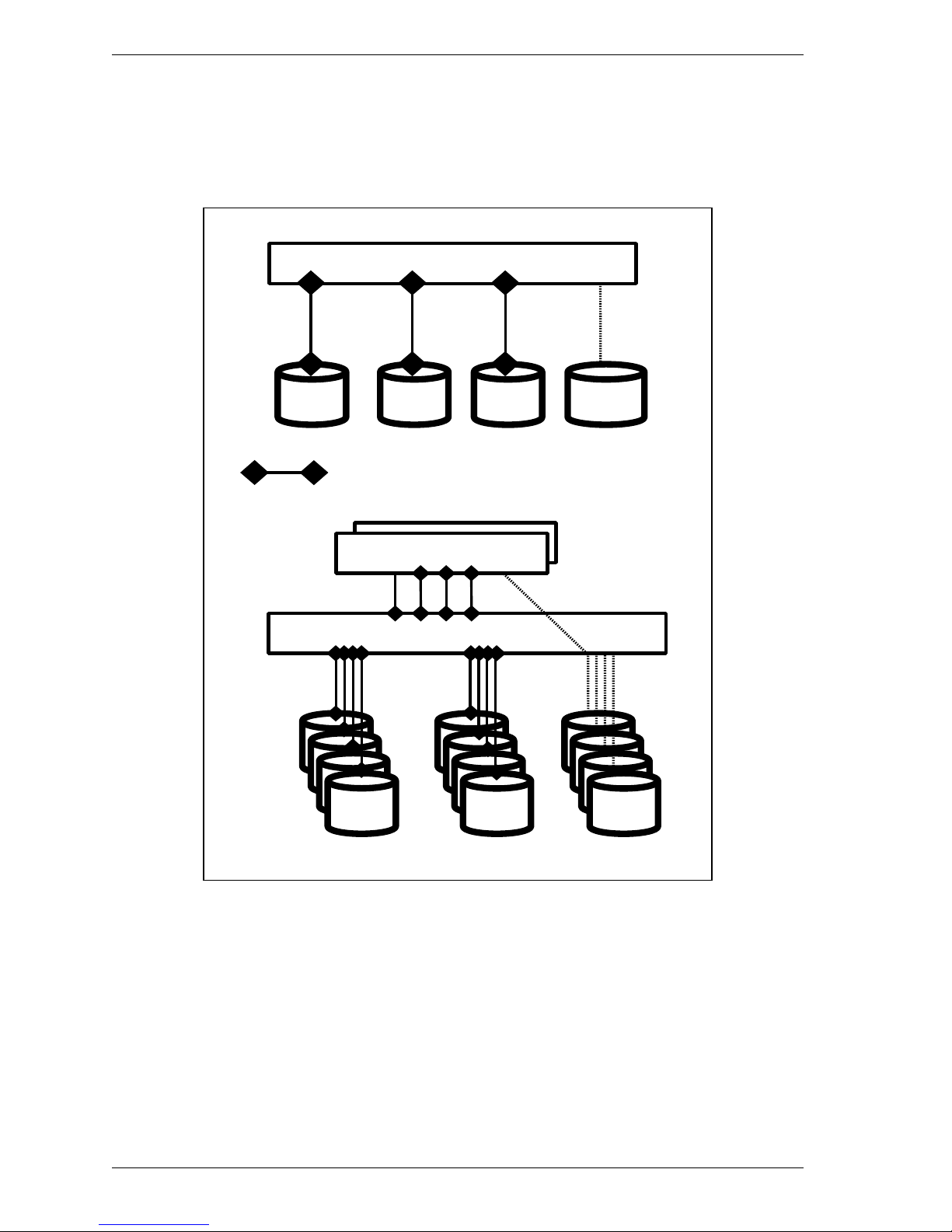
1.1 Topologies in SAS Interface
As shown in Figure 1.1, SAS drives have two connection patterns: point-topoint connection and expander connection.
SAS HBA (INIT)
SAS
Drive
SSP (Serial SCSI Protocol)
SMP
SAS Expander (s)
SAS
Drive
SAS
Drive
SAS HBAs (INIT)
SAS
Drive
SAS
Drive
SATA
Drive
STPSSPSSP
SATA
Drive
Figure 1.1 SAS drive connection patterns
SAS supports the three protocols listed below. Among these protocols, SAS
drives support only SSP.
• Serial SCSI Protocol (SSP)
• Serial ATA Tunneling Protocol (STP)
• Serial Management Protocol (SMP)
1-2 C141-C009
Page 25
1.1 Topologies in SAS Interface
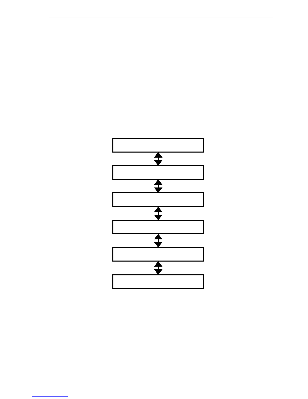
1.1.1 SAS Layering
As shown in Figure 1.2, for SAS, the following six control layers are defined:
• Physical layer: Electric properties related to cables, connectors,
and signals
• Phy (transceiver) layer: 8B/10B code, OOB, and speed negotiation
• Link layer: Primitives, address frames, and connection control
• Port layer: Wide port control
• Transport layer: Frame control
• Application layer: SCSI commands, mode pages, and log pages
Application layer
Transport layer
Port layer
Link layer
Phy layer
Physical layer
Figure 1.2 SAS control layers
C141-C009 1-3
Page 26
Serial Attached SCSI (SAS) Interface
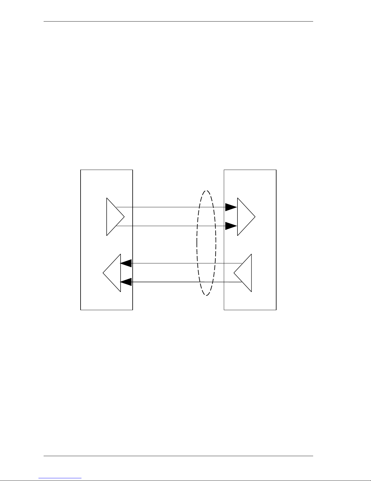
1.1.2 Physical links and phys
A physical link is a set of four wires used as two differential signal pairs. One
differential signal transmits in one direction while the other differential signal
transmits in the opposite direction. Data may be transmitted in both directions
simultaneously.
A physical phy contains a transceiver which electrically interfaces to a physical
link, which attaches to another physical phy.
Phys are contained in ports. Phys interface to the service delivery subsystem.
Figure 1.3 shows two phys attached with a physical link.
An attached phy is the phy to which a phy is attached over a physical link. A
device may contain one or more phys. Each phy has a phy identifier which is
unique within the device.
Phy
(Transceiver)
Physical link
Differential signal pair
Transmitter
Differential signal pair
Receiver
Figure 1.3 Physical links and phys
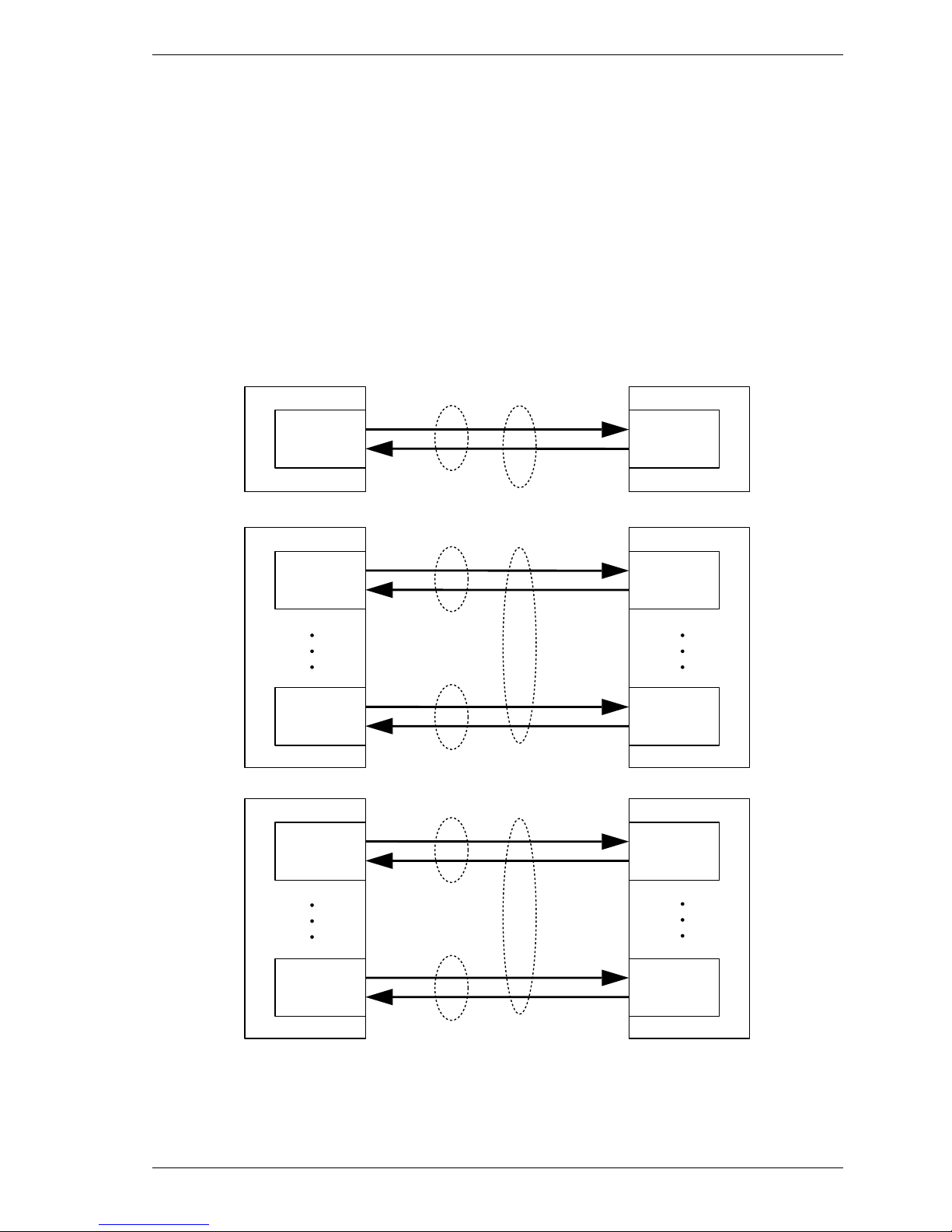
1.1.3 Ports (narrow ports and wide ports)
Phy
(Transceiver)
Receiver
Transmitter
A port contains one or more phys. Ports in a device are associated with physical
phys based on the identification sequence. A port is created from a set of physical
phys if one or more physical phys contained within a device:
a) transmit the same SAS address during the identification sequence; and
b) receive the same SAS address during the identification sequence (i.e., the
corresponding attached phy or phys transmit the same SAS address).
1-4 C141-C009
Page 27
1.1 Topologies in SAS Interface
A wide port is created if there is more than one phy in the port. A narrow port is a
port with only one phy.
A wide link is the set of physical links that attach a wide port to another wide
port. A narrow link is the physical link that attaches a narrow port to another
narrow port.
Figure 1.4 shows examples of narrow ports and wide ports, with a representation
of the SAS address transmitted during the identification sequence. Although
several phys on the left transmit SAS addresses of B, only phys attached to the
same SAS addresses become part of the same ports. The set of phys with SAS
address B attached to the set of phys with SAS address D become one port, while
the set of phys with SAS address B attached to the set of phys with SAS address E
become another port.
Narrow port
SAS address A
Phy Phy
Physical link
SAS address B
Wide port
Phy Phy
Physical link
SAS address B
Phy Phy
Physical link
SAS address B
Wide port
Narrow link
SAS address C
Wide link
SAS address D
SAS address D
Wide link
Narrow port
Wide port
Wide port
Phy Phy
Phy Phy
Figure 1.4 Ports (narrow ports and wide ports)
C141-C009 1-5
Physical link
SAS address B
Physical link
SAS address E
SAS address E
Page 28
Serial Attached SCSI (SAS) Interface
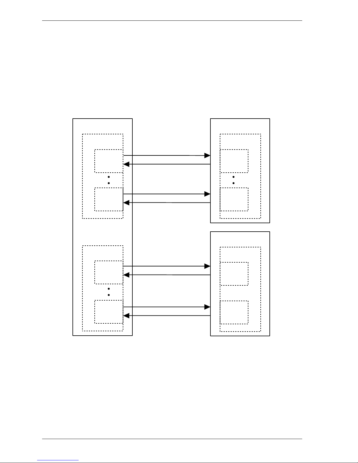
1.1.4 SAS devices
A SAS device contains one or more SAS ports, each containing one or more phys
(i.e., a SAS port may be a narrow port or a wide port).
Each single HDD unit is a separate SAS device. Usually, it is a single port or
dual port device, but does not use a wide port.
Figure 1.5 shows examples of SAS devices with different port and phy
configurations.
SAS Device SAS Device
Wide port
Phy
Phy
Wide port
Phy
Wide port
Phy
Phy
SAS Device
Narrow port
Phy
Narrow port
Phy
1-6 C141-C009
Phy
Figure 1.5 SAS devices
Page 29
1.1 Topologies in SAS Interface
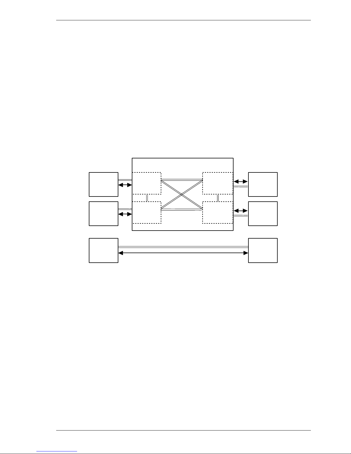
1.1.5 Pathways
A potential pathway is a set of physical links between a SAS INIT phy and a SAS
TARG phy. When a SAS INIT phy is directly attached to a SAS TARG phy,
there is one potential pathway. When there are expander devices between a SAS
INIT phy and a SAS TARG phy, there are multiple potential pathways, each
consisting of a set of physical links between the SAS INIT phy and the SAS
TARG phy. The physical links may or may not be using the same physical link
rate.
A pathway is a set of physical links between a SAS INIT phy and a SAS TARG
phy being used by a connection.
Figure 1.6 shows examples of potential pathways.
Expander device
Phy
Phy
Phy
Phy
Phy
Phy
Phy
Phy
Phy
Phy
Physical link Potential
pathway
Figure 1.6 Example of potential pathw ays
A partial pathway is the set of physical links participating in a connection request
that has not reached the destination phy (e.g., the OPEN address frame has been
transmitted by the source phy but the OPEN address frame has not yet reached the
destination phy).
A partial pathway is blocked when path resources it requires are held by another
partial pathway.
C141-C009 1-7
Page 30

Serial Attached SCSI (SAS) Interface
1.1.6 Connections
A connection is a temporary association between a SAS INIT port and a SAS
TARG port. During a connection all dwords from the SAS INIT port are
forwarded to the SAS TARG port, and all dwords from the SAS TARG port are
forwarded to the SAS INIT port.
A connection is pending when an OPEN address frame has been delivered along a
completed pathway to the destination phy but the destination phy has not yet
responded to the connection request. A connection is established when an
OPEN_ACCEPT is returned to the source phy.
A connection enables communication for one protocol: SSP, STP, or SMP. For
SSP and STP, connections may be opened and closed multiple times during the
processing of a command.
The connection rate is the effective rate of dwords through the pathway between a
SAS INIT phy and a SAS TARG phy, established through the connection request.
Every phy shall support a 1,5 Gbps connection rate regardless of its physical link
rate.
One connection may be active on a physical link at a time. If the connection is an
SSP or SMP connection and there are no dwords to transmit associated with that
connection, idle dwords are transmitted.
The number of connections established by a SAS port shall not exceed the
number of SAS phys within the SAS port (i.e., only one connection per SAS phy
is allowed). There shall be a separate connection on each physical link.
If multiple potential pathways exist between the SAS INIT port(s) and the SAS
TARG port(s), multiple connections may be established by a SAS port between
the following:
a) one SAS INIT port to multiple SAS TARG ports;
b) one SAS TARG port to multiple SAS INIT ports; or
c) one SAS INIT port to one SAS TARG port.
Once a connection is established, the pathway used for that connection shall not
be changed (i.e., all the physical links that make up the pathway remain dedicated
to the connection until it is closed).
1-8 C141-C009
Page 31

1.2 Names and identifiers
1.2 Names and identifiers
Device names are worldwide unique names for devices within a transport
protocol. Port names are worldwide unique names for ports within a transport
protocol. Port identifiers are the values by which ports are identified within a
domain, and are used as SAS addresses. Phy identifiers are unique within a
device.
1.2.1 SAS addresses
Table 1.1 defines the SAS address format. SAS addresses shall be compatible
with the NAA (Name Address Authority) IEEE Registered format identification
descriptor defined in SPC-3. The SAS address shall be worldwide unique. A SAS
address of 00000000_00000000h indicates an invalid SAS address.
Table 1.1 SAS address format
Bit
Byte
0 (MSB)
1
2
3 (LSB) (MSB)
4
5
6
7 (LSB)
7
6 5 4 3 2 1
IEEE COMPANY ID
0
SAS addresses represent any of three types of WWNs: a device SAS address
representing a device address, a port SAS address representing Port-A, or a port
SAS address representing Port-B.
The INQUIRY (page 83 command reports the device SAS address, while the
mode parameter (page 19) and log parameter (page 18) report port SAS addresses.
− device SAS address: 5CCC CCCX XXXX XXX yy00
− port SAS address (Port-A): 5CCC CCCX XXXX XXX yy10
− port SAS address (Port-B): 5CCC CCCX XXXX XXX yy11
C = 4 bits: Company ID
X = 4 bits: Serial number for WWN
y = 1 bit: Reserved
C141-C009 1-9
Page 32

Serial Attached SCSI (SAS) Interface
1.2.2 Hashed SAS address
SSP frames include a hashed version of the SAS address to provide an additional
level of verification of proper frame routing.
The code used for the hashing algorithm is a cyclic binary Bose, Chaudhuri, and
Hocquenghem (BCH) (63, 39, 9) codes. Table 1.2 lists the parameters for the
code.
Table 1.2 Hashed SAS address code parameter
Parameter Value
Number of bits per codeword 63
Number of data bits 39
Number of redundant bits 24
Minimum distance of the code 9
The generator polynomial for this code is:
G(x) = (x
6
+ x + 1) (x 6 + x 4 + x 2 + x + 1) (x 6 + x 5 + x 2 + x + 1) (x 6 + x 3 + 1)
After multiplication of the factors, the generator polynomial is:
G(x) = x
24
+ x 23 + x 22 + x 20 + x 19 + x 17 + x 16 + x 13 + x 10 + x 9 + x 8 + x 6 + x 5 +
x 4 + x 2 + x + 1
1-10 C141-C009
Page 33

1.3 Phy layer
1.3 Phy layer
In the phy layer, 8b10b coding and the link reset sequence are defined.
1.3.1 8b10b coding
All information transferred in SAS is encoded into 10-bit characters using 8b10b
encoding. Information includes data bytes representing data in a frame and
control characters used for frame delimiters.
Ten-bit characters are transferred in units of dwords, where a dword contains four
ten-bit characters.
A primitive is a dword that consists of a control character at the beginning and the
other three data characters.
In the SAS specifications, a primitive that starts with the K28.5 control character
and another one that starts with the K28.6 control character are defined. Table 1.3
shows the usage of special characters.
Table 1.3 Usage of special characters
Beginning character Usage in SAS Usage in SATA
K28.3
K28.5
K28.6
Primitive to be used only within STP
connection
ALIGN and most primitives that are
defined in SAS
SATA_ERROR
(used on the physical link layer of SATA)
All the primitives
except ALIGN
ALIGN
Not used.
Dxx.y Data Data
A single data dword is a dword that starts with a data character.
Running disparity shall be maintained separately on each physical link. During a
connection, expander devices shall convert incoming 10-bit characters to 8-bit
bytes and generate the 10-bit character with correct disparity for the output
physical link. Phys within a device may or may not begin operation with the same
disparity after the reset sequence.
Information to be transmitted across a physical link shall be encoded eight bits at
a time into a 10-bit character and then transmitted serially bit-by-bit across the
physical link. Information received over the physical link shall be collected ten
bits at a time, and those characters that are used for data, called data characters,
shall be decoded into the correct 8-bit data bytes. The 10-bit characters support all
256 8-bit combinations. 8b10b coding ensures that sufficient transitions are
present in the serial bit stream to make clock recovery possible at the receiver.
C141-C009 1-11
Page 34

Serial Attached SCSI (SAS) Interface
Such encoding also greatly increases the likelihood of detecting any single or
multiple bit errors that may occur during transmission and reception of
information. In addition, some of the control characters of the transmission code
contain a distinct and easily recognizable bit pattern called a comma pattern
which assists a receiver in achieving character and dword alignment on the
incoming bit stream.
1.3.2 Link reset sequence
The link reset sequence consists of the phy reset sequence and the identification
sequence. The phy reset sequence consists of the out of band (OOB) sequence
and speed negotiation sequence. The hard reset sequence is performed only when
the HARD_RESET primitive is detected after the completion of the speed
negotiation. The HARD_RESET primitive detected at any time later than the
identification sequence is invalid. The hard reset sequence corresponds to the
reset condition of pSCSI.
Figure 1.7 Reset-related terminology
1-12 C141-C009
Page 35

1.3 Phy layer
1.3.3 Start conditions of the link reset sequence
Drives start the link reset sequence when they detect any of the following
conditions:
• The power is turned on.
• A loss of signal is detected (OOB from the INIT).
• A loss of sync is detected.
• A HARD_RESET primitive is received during the link reset sequence.
• A hot-plug timeout (500 ms) is detected during the link reset sequence.
• The IDENTIFY address frame could not be received.
• A BREAK timeout is detected.
1.3.4 Out of band (OOB) signals
Out of band (OOB) signals are low-speed signal patterns detected by the phy that
do not appear in normal data streams. They consist of defined amounts of idle
time followed by defined amounts of burst time. During the idle time, D.C. idle is
transmitted. During the burst time, ALIGN (0) primitives are transmitted
repeatedly. The signals are differentiated by the length of idle time between the
burst times.
Table 1.4 OOB signal timing specif ications
Parameter Minimum Nominal Maximum Comments
OOB interval
(OOBI) *1
666,600 ps 666,666 ps 666,733 ps
The time basis for burst times and
idle times used to create OOB
signals. Based on 1,5 Gbps clock
tolerance.
The minimum time a receiver shall
COMSAS detect
timeout
13,65 µss
− −
allow to detect COMSAS after
transmitting COMSAS.
Derived from: OOBI × 512 × 40
*1 The OOBI is different from the UI (OOB) defined in SATA (for example,
stricter clock tolerance applies to SAS). This is because the OOBI is a
fixed value that is equal to the UI value of G1, and that does not depend on
actual transfer speed used to set up the burst time.
Table 1.5 describes the OOB signal transmitter requirements for the burst time,
idle time, and negation times that comprise each OOB signal.
C141-C009 1-13
Page 36

Serial Attached SCSI (SAS) Interface
Table 1.5 OOB signal transmitter requi rement s
Signal Burst time Idle time Negation time
COMINIT/RESET 160 OOBI 480 OOBI 800 OOBI
COMSAS 160 OOBI 1440 OOBI 2400 OOBI
To transmit an OOB signal, a transmitter shall repeat these steps six times:
1) transmit D.C. idle for an idle time; and
2) transmit an ALIGN burst for a burst time.
It shall then transmit D.C. idle for an OOB signal negation time.
The ALIGNs used in OOB signals should be at generation 1 (G1) physical link rates
(i.e., 1,5 Gbps). The ALIGNs are only required to generate an envelope for the
detection circuitry, as required for any signaling that may be A.C. coupled. If G2
ALIGNs are used, the number of ALIGNs doubles compared with G1 ALIGNs.
A SAS transmitter should transmit ALIGNs at the G1 physical link rate to create
the burst portion of the OOB signal, but may transmit ALIGNs at its lowest
supported physical link rate if it is not able to transmit at the G1 physical link rate
and shall not transmit them at a physical link rate faster than its lowest supported
physical link rate.
Figure 1.8 describes OOB signal transmission by the SP transmitter.
ALIGN burst
COMINIT
idle
ALIGN burst
1
1 2
1
COMRESET/COMINIT
3
2
3
4 5 6
2
3
4 5 6
COMSAS
4 5 6
COMINIT
Transmitt
COMINIT
negation
Transmitted
COMSAS
1
COMSAS i dle
2
Figure 1.8 OOB signal transmission
1-14 C141-C009
3
4 5 6
COMSAS
negation
Page 37

1.3 Phy layer
Table 1.6 describes the OOB signal receiver requirements for detecting burst
times, assuming Tburst is the length of the detected burst time. The burst time is
not used to distinguish between signals.
Table 1.6 OOB signal receiver burst time detect ion requirements
Signal
COMINIT/COMRESET
COMSAS
Table 1.7 describes the OOB signal receiver requirements for detecting idle times,
assuming Tidle is the length of the detected idle time.
Table 1.7 OOB signal receiver idle ti me det ect i on requirements
Signal
COMINIT/COMRESET
COMSAS
Table 1.8 describes the OOB signal receiver requirements for detecting negation
times, assuming Tidle is the length of the detected idle time.
Detection requirements
may detect shall detect
Tburst ≤ 100 ns
Tburst ≤ 100 ns
Tburst > 100 ns
Tburst > 100 ns
Detection requirements
may detect shall detect
175 ns ≤ Tidle < 525 ns 304 ns ≤ Tidle < 336 ns
525 ns ≤ Tidle < 1575 ns 911,7 ns ≤ Tidle < 1008 ns
Table 1.8 OOB signal receiver negation ti me det ect i on requirements
Signal Detection requirements
COMINIT/COMRESET Tidle > 525 ns
COMSAS Tidle > 1575 ns
A receiver shall detect an OOB signal after receiving four consecutive idle
time/burst time pairs. It is not an error to receive more than four idle time/burst
time pairs. A receiver shall not detect the same OOB signal again until it has
detected the corresponding negation time (i.e., a COMINIT negation time for a
COMINIT) or has detected a different OOB signal.
A SAS receiver shall detect OOB signals comprised of ALIGNs transmitted at
any rate up to its highest supported physical link rate. This includes physical link
rates below its lowest supported physical link rate (e.g., a SAS receiver
supporting only 3,0 Gbps detects 1,5 Gbps based ALIGNs, providing
interoperability with a SAS transmitter supporting both 1,5 Gbps and 3,0 Gbps).
C141-C009 1-15
Page 38

Serial Attached SCSI (SAS) Interface
Figure 1.9 describes SAS OOB signal detection by the SP receiver.
COMRESET/COMINIT
1 2 3 4 n
Any transitions
COMINIT
detected
COMINIT
negation
COMSAS
2
1
Any transitions
idle
3
nth
n
idle/Burst pair
4
n
COMSAS
negation
COMSAS
detected
ALIGN burst
Figure 1.9 OOB signal detection
1.3.5 SAS OOB sequency
During the OOB sequence, the INIT and the drive first send the COMINIT signal
to each other, then the COMSAS signal. When they both have received the
COMSAS signal from each other, the OOB sequence is recognized as having
been performed successfully. Depending on the power-on timing, reception of
the COMINIT signal from the other side may not be detected. In such a case,
however, the OOB sequence is recognized as having been performed successfully
if the COMINIT and COMSAS signals have been sent by the time the COMSAS
signal from the other side is received.
When the OOB sequence is successful, the SAS speed negotiation sequence
starts.
Figure 1.10 shows several different SAS OOB sequences between phy A and phy
B, with phy A starting the SAS OOB sequence at the same time as phy B, before
phy B, and before phy B powers on.
idle/Burst pair
1-16 C141-C009
Page 39

1.3 Phy layer
y
x
y
x
/
x
Scenario 1: Both SAS phys start SAS OOB sequence at same time
COMINIT
Phy A Tx/
Phy B Rx
Phy A Rx/
Phy B Tx
A
Time=0 Time=z
B
COMINIT COMSAS
Scenario 2: SAS phy A starts SAS OOB sequence
COMINIT
Phy A Tx/
Ph
B R
A
Time=0 T ime=z
COMSAS
COMSAS
Phy A Rx/
Ph
B T
B
COMINIT
Scenario 3: SAS phy B misses SAS phy A’s COMINIT
Phy A Tx
Phy B R
Phy A Rx/
Phy B Tx
A
COMINIT COMSAS
Time=0 Time=z
B
COMINIT
A: SAS phy A power on
B: SAS phy B power on
Time 0 : SAS phy reset sequence begins
Time z: SAS speed negotiation sequence begins
COMSAS
COMSAS
C141-C009 1-17
Figure 1.10 SAS to SAS OOB sequence
Page 40

Serial Attached SCSI (SAS) Interface
1.3.5.1 Exception handling in the OOB sequence
• When the COMINIT signal cannot be detected
When a drive sends the COMINIT signal but the COMINIT signal from the
other side cannot be detected, the drive waits for the reception of the
COMINIT signal from the INIT or expander until the hot-plug timeout time
(500 ms) elapses. If the hot-plug timeout time elapses before the COMINIT
signal from the other side has been received, the drive sends the COMINIT
signal again to start a new link reset sequence. If the drive receives the
COMSAS signal while waiting for the COMINIT signal, it sends the
COMSAS signal and takes the OOB sequence as having been performed
successfully in spite of the fact that it has not received the COMINIT signal.
• When the COMSAS signal cannot be det ected
When a drive sends the COMSAS signal but the COMSAS signal from the
other side cannot be detected, the drive waits for the reception of the
COMSAS signal from the INIT or expander until the hot-plug timeout time
(500 ms) elapses. If the hot-plug timeout time elapses before the COMSAS
signal from the other side has been received, the drive sends the COMSAS
signal again to start a new link reset sequence.
1.3.6 SAS speed negotiation sequence
The SAS speed negotiation sequence is a peer-to-peer negotiation technique that
does not assume initiator and target (i.e., host and device) roles. The sequence
consists of a set of speed negotiation windows for each physical link rate, starting
with 1,5 Gbps, then 3,0 Gbps, then the next rate. The length of the speed
negotiation sequence is determined by the number of physical link rates supported
by the phys.
Figure 1.11 defines the speed negotiation window, including:
a) speed negotiation window time;
b) rate change delay time (RCDT);
c) speed negotiation transmit time (SNTT); and
d) speed negotiation lock time (SNLT).
1-18 C141-C009
Page 41

1.3 Phy layer
Speed negotiation lock time(SNLT)
ALIGN(0)s ALIGN(1)s
Rate change delay time
(RCDT)
Speed negotiation window
Speed negotiation transmit time(SNTT)
Figure 1.11 SAS speed negotiation window
Table 1.9 defines the timing specifications for the SAS speed negotiation
sequence.
Table 1.9 SAS speed negotiation sequence timing speci fications
Parameter Time Comments
Rate change delay
time (RCDT)
750 000 OOBI
The time the transmitter shall transmit D.C.
idle between rates during speed negotiation.
The time during which ALIGN(0) or
Speed negotiation
transmit time (SNTT)
163 840 OOBI
ALIGN(1) is transmitted at each physical link
rate during the speed negotiation sequence.
Derived from: OOBI x 4096 x 40.
The maximum time during the speed
Speed negotiation
lock time (SNLT)
153 600 OOBI
negotiation window for a transmitter to reply
with ALIGN(1). Derived from:
OOBI x 3840 x 40
Speed negotiation
window time
913 840 OOBI
The duration of a speed negotiation window.
Derived from: RCDT + SNTT.
The speed negotiation sequence shall consist of the following transmission
sequence:
1) a transmission of D.C. idle for an RCDT; and
2) if the phy supports the physical link rate, a transmission of ALIGNs at that
physical link rate for the remainder of the entire speed negotiation window. If
the phy does not support the physical link rate, transmission of D.C. idle for
the remainder of the entire speed negotiation window.
C141-C009 1-19
Page 42

Serial Attached SCSI (SAS) Interface
If the phy supports the physical link rate, it shall attempt to synchronize on an
incoming series of dwords at that rate for the SNLT. The received dwords may be
ALIGN (0) or ALIGN (1) primitives. If the phy achieves dword synchronization
within the SNLT, it shall change from transmitting ALIGN (0) primitives to
transmitting ALIGN (1) primitives for the remainder of the SNTT (i.e., the
remainder of the speed negotiation window). If the phy does not achieve dword
synchronization within the SNLT, it shall continue transmitting ALIGN (0)s for
the remainder of the SNTT (i.e., the remainder of the speed negotiation window).
At the end of the SNTT, if a phy is both transmitting and receiving ALIGN (1)
primitives, it shall consider that physical link rate valid. The phy shall then
proceed to the next speed negotiation window. A phy shall participate in all speed
negotiation windows:
a) up to its highest supported physical link rate plus one; or
b) until it runs a speed negotiation window that does not detect a valid physical
link rate after having detected a valid physical link rate in a previous speed
negotiation window.
If the phy has detected a valid physical link rate in the previous speed negotiation
window, it shall enter the final speed negotiation window using the highest
previously successful link rate.
Figure 1.12 shows speed negotiation between a phy A that supports G1 through
G3 link rates and a phy B that only supports the G2 link rate. Both phys run:
1) the G1 speed negotiation window, supported by phy A but not by phy B;
2) the G2 speed negotiation window, supported by both phys; and
3) the G3 speed negotiation window, supported by phy A but not by phy B.
Both phys then select G2 for the final speed negotiation window to establish the
negotiated physical link rate.
1-20 C141-C009
Page 43

1.3 Phy layer
y
y
y
x
x
y
(neg
)
x
/
Phy A Tx/
Phy B R
Phy A Rx/
Phy B T
no dword
s
RCD
nc
SNTT
RCD
RCD
SNTT
ALIGN(0)s ALIGN(1)s
Not supported
by phy B
G1 rate G2 rate G3 rate
RCD
dword
s
nc
SNTT
dword
s
nc
SNTT SNTT
Time z: SAS speed negotiation sequence begins
RCD
Not supported
no dword
s
nc
SNTT SNTT
by phy B
Time
Figure 1.12 SAS speed negotiation sequence (Example 1)
If the phy does not obtain dword synchronization during the final speed negotiation
window, the SAS speed negotiation sequence fails.
RCD
RCD
dword
sync
dword
sync
SNTT
G2 rate
otiated rate
Phy A Tx/
Phy B R
Phy A Rx
Phy B Tx
Figure 1.13 shows the same speed negotiation sequence as in Figure 1.12 when phy B
does not obtain dword synchronization during the final speed negotiation window. If
this occurs, the handshake is not complete and the OOB sequence shall be retried
starting with COMINIT, forcing the phy to retry the whole reset sequence.
dword
sync
RCD
SNTT SNTT
dword
RCD
sync
SNTT
G1 rate
ALIGN(0)s
dword
sync
RCD RCD
dword
RCD RCD
sync
SNTT
G2 rate
ALIGN(1)s
no dword
sync
SNTT
SNTT
G3 rate
Time z: SAS speed negotiation sequence begins
dword
sync
SNTT
no dword
sync
RCD
SNTT
G2 rate
(negotiated rate)
Time
COMINIT
COMINIT
Hot Plug
Timeout delay
Figure 1.13 SAS speed negotiation sequence (Example 2)
C141-C009 1-21
Page 44

Serial Attached SCSI (SAS) Interface
T
1.3.6.1 Phy reset sequence after devices are attached
Since SAS signal cable connector does not include power lines, it is not possible
to detect the physical insertion of the signal cable connector onto a plug. Noncabled environments may similarly not have a way to detect physical insertion of
a device. As a result, every time a phy reset sequence is originated:
Figure 1.14 shows how two phys complete the phy reset sequence if the phys are
not attached at power on. In this example, phy A and phy B are attached some
time before phy B’s second hot-plug timeout occurs. Phy B’s OOB detection
circuitry detects a COMINIT after the attachment, and therefore phy B transmits
COMSAS, since it has both transmitted and received a COMINIT. Upon
receiving COMSAS, phy A transmits its own COMSAS. The SAS speed
negotiation sequence follows.
Phy A Tx
COMINI
Hot-Plug
Timeout
COMINIT
Hot-Plug
Timeout
COMINIT COMSAS
A
Phy A Rx
Phy B Tx
Phy B Rx
Time=0
Time=y
B
Incomplete
COMINIT
COMINIT
B
Time=0
Hot-Plug
Timeout
Time=y
COMINIT
COMSAS
COMSAS
A
COMINIT
Time=z
Time=z
COMSAS
A: SAS phy A power on
B: SAS phy B power on
Time y : SAS phy A attached to SAS phy B
Time z: SAS phy A and SAS phy B start the SAS speed negotiation sequence
Figure 1.14 Phy reset sequence (Example)
1-22 C141-C009
Page 45

1.3 Phy layer
1.3.6.2 When the speed negotiation sequence is successful
When the speed negotiation sequence is successful, the identification sequence
(sending and receiving the IDENTIFY frame) is performed subsequently.
However, the INIT may have started the hard reset sequence at the time when the
drive starts the identification sequence. In this case, the drive will start the link
reset sequence, because it receives the HARD_RESET.
1.3.6.3 Exception handling in the speed negotiati on sequence
• When synchronization cannot be established at the G1 or G2 rate
• When synchronization cannot be established at the last negotiated rate
In both of the cases referred to above, the speed negotiation sequence is
considered to have failed. The drive waits for the reception of the COMINIT
signal from the INIT or expander until the hot-plug timeout time (500 ms)
elapses. When the hot-plug timeout time elapses before the signal has been
received from the other side, the drive sends the COMINIT signal again to start a
new link reset sequence. At the same time, the value in the PHY RESET
PROBLEM field of the Protocol-Specific log page (page 18) is incremented when
synchronization cannot be established at the last negotiated rate.
1.3.7 Phy layer dword synchronization (DWS)
The dword synchronization monitoring performed by the drive after the
completion of the speed negotiation sequence has the following characteristics:
1) In the idle state (the state where random data is being sent and/or received
without the transfer of frames or primitives), invalid dwords received are
ignored.
2) The DWS reset timeout timer (1 ms) is not supported.
3) When four invalid dwords are detected in a frame (address frame or SSP
frame), the dword synchronization is considered to have been lost. At this
time, the drive starts the link reset sequence without monitoring whether any
valid primitive is received (and without trying to establish resynchronization).
C141-C009 1-23
Page 46

Serial Attached SCSI (SAS) Interface
1.4 Link layer
The link layer defines primitives, address frames, and connections.
1.4.1 Primitives
Table 1.10 defines the primitives not specific to the type of connection.
Table 1.10 Primitives not specif i c t o type of connection (1/2)
From To Sequence
Primitive USE (*4)
I E T I E T Type
AIP (NORMAL) NoConn - E - I E T single supported supported
AIP (RESERVED 0) NoConn - - - I E T single
AIP (RESERVED 1) NoConn - - - I E T single
AIP (RESERVED 2) NoConn - - - I E T single
AIP (WAITING ON CONNECTION) NoConn - E - I E T single supported supported
AIP (WAITING ON DEVICE) NoConn - E - I E T single supported supported
AIP (WAITING ON PARTIAL) NoConn - E - I E T single supported supported
AIP (RESERVED WAITING ON PARTIAL) NoConn - - - I E T single
ALIGN (0) ALL I E T I E T single supported supported
ALIGN (1) ALL I E T I E T single supported supported
ALIGN (2) ALL I E T I E T single supported supported
ALIGN (3) ALL I E T I E T single supported supported
BREAK ALL I E T I E T redundant supported supported
SAS 1.1 rev7
supported prim
↑
↑
↑
↑
FJ supported
prim
Supported (*1)
Supported (*1)
Supported (*1)
Supported (*1)
BROADCAST (CHANGE) NoConn I E - I E T redundant supported ignored
BROADCAST (RESERVED CHANGE 0) NoConn - - - I E T redundant
BROADCAST (RESERVED CHANGE 1) NoConn - - - I E T redundant
BROADCAST (SES) NoConn - - T I E T redundant supported ignored
BROADCAST (RESERVED 1) NoConn - - - I E T redundant reserved ignored
BROADCAST (RESERVED 2) NoConn - - - I E T redundant reserved ignored
BROADCAST (RESERVED 3) NoConn - - - I E T redundant reserved ignored
BROADCAST (RESERVED 4) NoConn - - - I E T redundant reserved ignored
CLOSE (NORMAL) Conn I - T I - T triple supported supported
CLOSE (RESERVED 0) Conn - - - I - T triple
CLOSE (RESERVED 1) Conn - - - I - T triple
CLOSE (CLEAR AFFILIATION) STP I - - - - T triple ↑(Not STP) ignored
1-24 C141-C009
↑
↑
↑
↑
ignored
ignored
ignored
ignored
Page 47

1.4 Link layer
Table 1.10 Primitives not specif i c t o type of connection (2/2)
From To Sequence
Primitive USE (*4)
I E T I E T Type
EOAF NoConn I E T I E T single supported supported
ERROR ALL - E - I E T single supported supported
HARD RESET NoConn I E - I E T redundant supported supported
NOTIFY (ENABLE SPINUP) ALL I E - I E T single supported supported
NOTIFY (RESERVED 0) ALL - - - I E T single reserved ignored
NOTIFY (RESERVED 1) ALL - - - I E T single reserved ignored
NOTIFY (RESERVED 2) ALL - - - I E T single reserved ignored
OPEN_ACCEPT NoConn I - T I - T single supported supported
OPEN_REJECT (RETRY) NoConn I - T I - T single supported supported
OPEN_REJECT (RESERVED CONTINUE 0) NoConn - - - I - T single
OPEN_REJECT (RESERVED CONTINUE 1) NoConn - - - I - T single
OPEN_REJECT (BAD DESTINATION) NoConn - E - I - T single supported supported
OPEN_REJECT (CONNECTION RATE NOT
SUPPORTED)
OPEN_REJECT (NO DESTINATION) NoConn - E - I - T single supported supported
NoConn I E T I - T single supported supported
SAS 1.1 rev7
supported prim
↑
↑
↑
↑
FJ supported
prim
↑
OPEN_REJECT (RESERVED INITIALIZE 0) NoConn - - - I - T single
OPEN_REJECT (RESERVED INITIALIZE 1) NoConn - - - I - T single
OPEN_REJECT (PATHWAY BLOCKED) NoConn - E - I - T single supported supported
OPEN_REJECT (RESERVED STOP 0) NoConn - - - I - T single
OPEN_REJECT (RESERVED STOP 1) NoConn - - - I - T single
OPEN_REJECT (PROTOCOL NOT
SUPPORTED)
OPEN_REJECT (STP RESOURCES BUSY) NoConn - E T I - - single supported supported (*2)
OPEN_REJECT (WRONG DESTINATON) NoConn I - T I - T single supported supported
OPNE_REJECT (RESERVED ABANDON 0) NoConn - - - I - T single
OPNE_REJECT (RESERVED ABANDON 1) NoConn - - - I - T single
OPNE_REJECT (RESERVED ABANDON 2) NoConn - - - I - T single
OPNE_REJECT (RESERVED ABANDON 3) NoConn - - - I - T single
SOAF NoConn I E T I E T single supported supported
NoConn I - T I - T single supported supported
↑
↑
↑
↑
↑
↑
↑
↑
↑
↑
↑
↑
↑
↑
↑
Table 1.11 defines the primitives used only inside SSP and SMP connections.
C141-C009 1-25
Page 48

Serial Attached SCSI (SAS) Interface
Table 1.11 Primitives used only inside SSP and SMP connections
From To Sequence
Primitive USE (*4)
I E T I E T Type
ACK Conn I - T I - T single supported supported
CREDIT_BLOCKED Conn I - T I - T single supported supported
DONE (NORMAL) Conn I - T I - T single supported supported
DONE (RESERVED 0)
DONE (RESERVED 1)
DONE (ACK/NAK TIMEOUT) Conn I - T I - T single supported supported
DONE (RESERVED TIMEOUT 0)
DONE (RESERVED TIMEOUT 1)
DONE (CREDIT TIMEOUT) Conn I - T I - T single supported supported
EOF Conn I - T I - T single supported supported
NAK (CRC ERROR) Conn I - T I - T single supported supported
NAK (RESERVED 0) Conn - - - I - T single
NAK (RESERVED 1) Conn - - - I - T single
Conn - - - I - T single
Conn - - - I - T single
Conn - - - I - T single
Conn - - - I - T single
SAS 1.1 rev7
supported prim
↑
↑
↑
↑
↑
↑
FJ supported
prim
supported (*3)
supported (*3)
supported (*3)
supported (*3)
ignored
ignored
NAK (RESERVED 2) Conn - - - I - T single
RRDY (NORMAL) Conn I - T I - T single supported supported
RRDY (RESERVED 0) Conn - - - I - T single
RRDY (RESERVED 1) Conn - - - I - T single
SOF Conn I - T I - T single supported supported
↑
↑
↑
ignored
ignored
ignored
(*1) These primitives are received as AIP primitives.
(*2) When this primitive is received, the connection request is canceled and the
command is aborted.
(*3) These primitives are received as DONE primitives.
(*4) When a primitive falling under "NoConn" is received during the inside
connection, this primitive is discarded. When a primitive falling under
"NoConn" is received during the outside connection, this primitive is also
discarded. As for the HARD_RESET primitive, when it is received at any
time except during the period between the completion of the speed
negotiation and the reception of the first valid address frame, the received
HARD_RESET primitive is discarded as well.
1-26 C141-C009
Page 49

1.4 Link layer
1.4.2 Primitive sequences
Table 1.12 summarizes the types of primitive sequences.
Table 1.12 Primitive sequences
Primitive
sequence type
Number of times the transmitter
transmits the primitive to transmit
the primitive sequence
Number of times the receiver
receives the primitive to detect the
primitive sequence
Single 1 1
Triple 3 3
Redundant 6 3
Any number of ALIGNs and NOTIFYs may be sent inside primitive sequences
without affecting the count or breaking the consecutiveness requirements. Rate
matching ALIGNs and NOTIFYs shall be sent inside primitive sequences inside
of connections if rate matching is enabled.
1.4.3 Primitives not specific to type of connections
1.4.3.1 AIP (Arbitration in progress)
AIP is sent by an expander device after a connection request to specify that the
connection request is being processed and specify the status of the connection
request.
A drive performs the following processing when an AIP primitive is received:
1) When the drive receives an AIP primitive after sending the OPEN frame, the
2) When the drive receives an AIP primitive before sending the OPEN frame,
3) In a case of OPEN cross (a case where both the drive and initiator send the
1.4.3.2 ALIGN
ALIGNs are used for:
a) OOB signals;
b) character and dword alignment during the speed negotiation sequence;
c) clock skew management after the phy reset sequence;
d) rate matching during connections; and
drive initializes the open timer held in the drive, and restarts it.
the received AIP primitive is discarded.
OPEN frame), when the drive receives an AIP primitive after sending the
OPEN frame and, then, receives the OPEN frame from the expander, the
drive does not perform the arbitration fairness procedure. Instead, the
attempt from the drive is treated as unsuccessful, and the drive sends the
OPEN_ACCEPT or an OPEN_REJECT primitive.
C141-C009 1-27
Page 50

Serial Attached SCSI (SAS) Interface
Phys shall use ALIGN (0) to construct OOB signals as described in 6.6. Phys
shall use ALIGN (0) and ALIGN (1) during the speed negotiation sequence as
described in 6.7.4.2. Phys shall rotate through ALIGN (0), ALIGN (1), ALIGN
(2), and ALIGN (3) for all ALIGNs sent after the phy reset sequence.
1.4.3.3 BREAK
The BREAK primitive is used to cancel the connection request, or to cancel the
connection. The BREAK primitive is sent in cases 1) to 4) shown below.
1) When the connection request is to be canceled after sending an OPEN frame
2) When neither OPEN_ACCEPT nor OPEN_REJECT primitive is received
within 1 ms of sending an OPEN frame
3) When neither a DONE primitive nor an SSP frame is received within 1 ms of
sending a DONE primitive
4) When a CLOSE primitive is not received within 1 ms of sending a CLOSE
primitive
When the BREAK primitive is sent in any of the cases above, the BREAK timer
(1 ms) is started in anticipation of the reception of the BREAK primitive within 1
ms. If the BREAK primitive is not received within 1 ms, the connection is
regarded as having been closed.
After the BREAK primitive is sent, when any primitives and/or frames other than
the BREAK primitive are received, all of these (except NOTIFY primitives) are
discarded.
When the BREAK primitive is not received within 1 ms of sending the BREAK
primitive, a drive may start the link reset sequence.
1.4.3.4 BROADCAST
BROADCASTs are used to notify all SAS ports in a domain of an event.
When an expander port receives a BROADCAST it shall transmit the same
BROADCAST on at least one phy in all other expander ports. BROADCAST shall
only be sent outside of connections after the phy reset sequence has completed.
BROADCAST (CHANGE) is sent by an expander device to notify SAS INIT
ports and other expander devices that a configuration change has occurred.
BROADCAST (CHANGE) may also be transmitted by SAS INIT ports.
BROADCAST (CHANGE) shall be ignored by SAS TARG ports.
BROADCAST (SES) is sent by a SAS TARG port to notify SAS INIT ports that
an asynchronous event has occurred in an enclosure, and SSP INIT ports should
poll all the SCSI enclosure services logical units in the SAS domain.
BROADCAST (SES) shall be ignored by SAS TARG ports.
The drive ignores all received BROADCAST primitives.
1-28 C141-C009
Page 51

1.4 Link layer
1.4.3.5 CLOSE
A CLOSE primitive is used to close a connection. When a CLOSE primitive is
sent, the close timer (1 ms) is started. If a CLOSE primitive is not received
within 1 ms of sending CLOSE primitive, the BREAK primitive is sent. The
recipient must send a CLOSE primitive within 1 ms of receiving a CLOSE
primitive.
Drives support only the CLOSE (NORMAL) primitive as a CLOSE primitive,
while the CLOSE (CLEAR AFFILIATION), CLOSE (RESERVED 0), and
CLOSE (RESERVED 1) primitives are ignored.
1.4.3.6 EOAF (End of address frame)
EOAF specifies the end of an address frame.
1.4.3.7 ERROR
ERROR should be sent by an expander device when it is forwarding dwords from
a SAS physical link or SATA physical link to a SAS physical link and it receives
an invalid dword or an ERROR.
When a drive receives an ERROR primitive, the drive discards it. When a
received address frame contains the ERROR primitive, the whole address frame is
discarded even if CRC is correct.
When a drive receives an SSP frame containing the ERROR primitive, the drive
discards the whole SSP frame even if CRC is correct, and sends the NAK
primitive.
1.4.3.8 HARD_RESET
HARD_RESET is used to force a phy to generate a hard reset to its port. This
primitive is only valid after the phy reset sequence without an intervening
identification sequence and shall be ignored at other times.
Upon receipt of the HARD_RESET primitive, a drive clears all the commands it
is currently holding.
In a dual port drive, the HARD_RESET primitive received at one port (e.g., at
port A) affects the other port (e.g., at port B).
Meanwhile, as can be expected, a link reset sequence that occurs at one port (e.g.,
port A) does not affect the other port (e.g., port B).
C141-C009 1-29
Page 52

Serial Attached SCSI (SAS) Interface
1.4.3.9 NOTIFY
The NOTIFY (ENABLE SPINUP) primitive is sent by a SAS INIT device or
expander device. When receiving the NOTIFY (ENABLE SPINUP) primitive in
the active wait state of SCSI power conditions, a drive enters the active state.
A NOTIFY primitive is sometime used as a substitute for an ALIGN primitive,
and it is sent by the initiator or expander at regular intervals.
A SAS TARG device with multiple SAS TARG ports treats the NOTIFY
(ENABLE SPINUP) primitives from all the SAS TARG ports equally (for
example, the NOTIFY (ENABLE SPINUP) primitive received through SAS
TARG port A is treated as the wakeup for the START STOP UNIT command
received through SAS TARG port B).
The NOTIFY (RESERVED 0), NOTIFY (RESERVED 1), and NOTIFY
(RESERVED 2) primitives are ignored by all devices.
1.4.3.10 OPEN_ACCEPT
The OPEN_ACCEPT primitive indicates the acceptance of a connection request.
The recipient of an OPEN frame must send the OPEN_ACCEPT primitive within
1 ms, when it can accept the connection request.
1.4.3.11 OPEN_REJECT
An OPEN_REJECT primitive indicates the rejection of a connection request.
Among the OPEN_REJECT primitives, there are those indicating that the
connection request cannot be continued (OPEN_REJECT abandon primitives)
and those indicating that the connection request can be retried (OPEN_REJECT
retry primitives).
The OPEN_REJECT primitives defined in Table 1.13 direct the recipients to
abandon the connection request.
1-30 C141-C009
Page 53

1.4 Link layer
Table 1.13 OPEN_REJECT abandon primitives
Primitive Issuer
OPEN_REJECT
(BAD DESTINATION)
OPEN_REJECT
(CONNECTION RATE NOT
SUPPORTED)
OPEN_REJECT
(PROTOCOL NOT
SUPPORTED)
OPEN_REJECT
(RESERVED ABANDON 0)
Processing by the drive that receives the OPEN_REJECT
primitive
Expander
phy
Any phy 1) When the physical li nk rate is 3.0 Gbps and t he connection
Destination
phy
Unknown
Cancels the connection request, and aborts the TASK
(command).
link rate is 3.0 Gbps, the drive changes the connecti on rate to
1.5 Gbps, and resends the OPEN frame.
2) When the physical link rate is 3.0 Gbps and the connection
link rate is 1.5 Gbps, the drive changes the connecti on rate to
3.0 Gbps, and resends the OPEN frame.
3) When the physical link rate is 1.5 Gbps and the
connection link rate is 1.5 Gbps, the drive cancels
connection request, and aborts the TASK (command).
* After sending an OPEN frame in case 1) or 2), if the
drive receives this OPEN_REJECT primitive again, the
drive cancels the connection request, and aborts the
TASK (command).
If the driver receives this OPEN_REJECT primitive, it
cancels the connection request, and aborts the TASK
(command).
Performs the same processing as the OPEN_REJECT
(WRONG DESTINATION).
OPEN_REJECT
(RESERVED ABANDON 0)
OPEN_REJECT
(RESERVED ABANDON 0)
OPEN_REJECT
(RESERVED ABANDON 0)
OPEN_REJECT
(STP RESOURCES BUSY)
OPEN_REJECT
(WRONG DESTINATION)
All of the OPEN_REJECT versions defined in Table 1.14 shall result in the
originating device retrying the connection request.
Unknown
Unknown
Unknown
Destination
phy
Destination
phy
Performs the same processing as the OPEN_REJECT
(WRONG DESTINATION).
Performs the same processing as the OPEN_REJECT
(WRONG DESTINATION).
Performs the same processing as the OPEN_REJECT
(WRONG DESTINATION).
Performs the same processing as the OPEN_REJECT
(WRONG DESTINATION).
If the driver receives this OPEN_REJECT primitive, it
cancels the connection request, and aborts the TASK
(command).
C141-C009 1-31
Page 54

Serial Attached SCSI (SAS) Interface
Table 1.14 OPEN_REJECT retry primiti ves
Primitive Issuer
OPEN_REJECT
(NO DESTINATION)
OPEN_REJECT
(PATHWAY BLOCKED)
OPEN_REJECT
(RESERVED CONTINUE 0)
OPEN_REJECT
(RESERVED CONTINUE 1)
Expander
phy
Expander
phy
Unknown
Unknown
Processing by the drive that receives the OPEN_REJECT
primitive
1) I f the I_Tnexus loss timer is working, the d rive leaves the
timer working. If the I_Tnexus loss timer has expired,
the drive aborts all the command s of the relevant initiator.
Otherwise, if the timer has not expired, the drive resends
the OPEN frame.
2) If the I_Tnexus loss timer is stopped and it has expired,
the drive aborts all the command s of the relevant initiator.
Otherwise, if the timer has not expired, the drive
initializes the timer and resends the OPEN frame.
1) I f the I_Tnexus loss timer is working, the d rive leaves the
timer working. If the I_Tnexus loss timer has expired,
the drive aborts all the command s of the relevant initiator.
Otherwise, if the timer has not expired, the drive resends the
OPEN frame. At this time, the drive increments the
PATHWAY BLOCKED COUNT field in the OPEN frame.
Performs the same processing as the OPEN_REJECT
(RETRY).
Performs the same processing as the OPEN_REJECT
(RETRY).
OPEN_REJECT
(RESERVED INITIALIZE 0)
OPEN_REJECT
(RESERVED INITIALIZE 1)
OPEN_REJECT
(RESERVED STOP 0)
OPEN_REJECT
(RESERVED STOP 1)
OPEN_REJECT (RETRY) a
When an INIT sends an OPEN frame to a drive but the drive cannot accept the
connection request, the drive sends an OPEN_REJECT within 1ms. A drive
sends an OPEN_REJECT primitive in any of the following cases:
1) When the INIT port bit in a received OPEN frame is 0, the drive sends the
OPEN_REJECT (PROTOCOL NOT SUPPORTED) primitive.
2) When the PROTOCOL field in a received OPEN frame is not SSP, the drive
sends the OPEN_REJECT (PROTOCOL NOT SUPPORTED) primitive.
Unknown
Unknown
Unknown
Unknown
Destination
phy
Performs the same processing as the OPEN_REJECT (NO
DESTINATION).
Performs the same processing as the OPEN_REJECT (NO
DESTINATION).
Performs the same processing as the OPEN_REJECT
(PATHWAY BLOCKED).
Performs the same processing as the OPEN_REJECT
(PATHWAY BLOCKED).
Otherwise, if the I_Tnexus loss timer is wor k ing, the drive
stops the timer and resends the OPEN frame.
1-32 C141-C009
Page 55

1.4 Link layer
3) When the CONNECTION RATE field in the received OPEN frame is not
"1.5G or 3.0G", the drive sends the OPEN_REJECT (CONNECTION RATE
NOT SUPPORTED) primitive.
4) When, in contradiction to the fact that the physical link rate is 1.5 Gbps, the
CONNECTION RATE field in a received OPEN frame is 3.0G, the drive
sends the OPEN_REJECT (CONNECTION RATE NOT SUPPORTED)
primitive.
5) A single port drive may process requests from up to eight INITs at the same
time. When a single port drive holds commands from eight initiators, and if
it receives a connection request from a ninth initiator, the drive sends the
OPEN_REJECT (RETRY) primitive.
6) A dual port drive may process requests from up to four INITs at a time for
each port. When a dual port drive holds commands from four INITs for one
of its ports, and if it receives a connection request from a fifth INIT through
the same port, the drive sends the OPEN_REJECT (RETRY) primitive.
7) When the drive cannot receive an SSP frame temporarily due to the recovery
processing of an internal drive error, the drive sends the OPEN_REJECT
(RETRY) primitive.
8) When the SAS address of a drive does not match the DESTINATION SAS
ADDRESS field in a received OPEN frame, the drive sends the
OPEN_REJECT (WRONG DESTINATION) primitive.
1.4.3.12 SOAF (Start of address fr ame)
SOAF specifies the start of an address frame.
C141-C009 1-33
Page 56

Serial Attached SCSI (SAS) Interface
1.4.4 Primitives used only inside SSP and SMP connections
1.4.4.1 ACK (acknowledge)
The ACK primitive indicates that an SSP frame is received normally. When a
drive receives an SSP frame, and the CRC field in the received SSP frame is
correct, the drive sends the ACK primitive within 1 ms.
1.4.4.2 CREDIT_BLOCKED
The CREDIT_BLOCKED primitive indicates that no more credits can be sent
during this connection. When a drive determines that it can give out no more
credits during the connection, the drive sends the CREDIT_BLOCKED primitive
to avoid credit timeout. A drive sends the CREDIT_BLOCKED primitive in any
of the following cases:
1) When the drive sends an OPEN frame and, then, receives the OPEN_ACCEPT
primitive from the initiator during the abort processing in the drive, the drive
sends the CREDIT_BLOCKE D primitive instead of an RRD Y primitive.
2) When the drive determines during the connection that it has entered a
After sending the CREDIT_BLOCKED primitive,the drive must wait until the
connection is closed before it can send an RRDY primitive.
Meanwhile, when a drive receives the CREDIT_BLOCKED primitive from the
initiator, the drive performs any of the following processing:
1) At the time of the receipt of the CREDIT_BLOCKED primitive, if the drive
2) At the time of the receipt of the CREDIT_BLOCKED primitive, if the drive holds
3) At the time of the receipt of the CREDIT_BLOCKED primitive, if the drive
1.4.4.3 DONE
condition where abort processing inside the drive is necessary, if an SSP
frame is received from the initiator, the drive sends the CREDIT_BLOCKED
primitive instead of an RRDY primitive.
holds credits that have been given before and has frames to send, the drive
can send as many frames as there are credits being held at this time.
credits that have been given before but has no frames to send, the drive sends the
DONE (CREDIT TIMEOUT) primitive and starts the close processing.
holds no credits, it sends the DONE (CREDIT TIMEOUT) primitive and
starts the close processing.
A DONE primitive indicates the start of the close processing of an SSP
connection. In the close processing, in principle, when no frame for processing
remains on the side of the OPEN frame sender (recipient of the OPEN_ACCEPT
primitive), a DONE primitive is sent. However, there is no rule concerning which
side should first start the close processing.
Table 1.15 contains DONE primitive definitions.
1-34 C141-C009
Page 57

1.4 Link layer
Table 1.15 DONE primitives
primitive Description
DONE
(ACK/NAK TIMEOUT)
DONE
(RESERVED TIMEOUT 0)
DONE
(RESERVED TIMEOUT 1)
When the sender of an SSP frame does neither receive the
ACK nor the NAK primitive after sending the SSP frame, the
sender sends the DONE (ACK/NAK TIMEOUT) primitive.
This primitive is processed in the same manner as the DONE
(ACK/NAK TIMEOUT) primitive.
This primitive is processed in the same manner as the DONE
(ACK/NAK TIMEOUT) primitive.
DONE (NORMAL) Indicates that all frames have been sent.
DONE (RESERVED 0)
DONE (RESERVED 1)
This primitive is processed in the same manner as the DONE
(NORMAL) primitive.
This primitive is processed in the same manner as the DONE
(NORMAL) primitive.
When the wait time for an RRDY primitive has exceeded 1
DONE (CREDIT
TIMEOUT)
ms, or the CREDIT BLOCKED primitive is received before
an RRDY primitive is received, if the close processing is
performed, the DONE (CREDIT TIMEOUT) primitive is
sent.
A drive sends a DONE primitive in any of the following cases:
1) When the drive sends an OPEN frame and establishes connection, and it
becomes that there are no frame to be sent, the drive sends the DONE
(NORMAL) primitive.
2) When credit timeout is detected before the drive sends an SSP frame, the
drive sends the DONE (CREDIT TIMEOUT) primitive.
3) When the drive receives the CREDIT_BLOCKED primitive during an inside
connection, the drive sends the DONE (CREDIT TIMEOUT) primitive
during the close processing.
4) When an OPEN frame is sent by an initiator, connection is established, and
no SSP frame has been sent for more than 1 ms, the drive sends the DONE
(NORMAL) primitive.
5) When the drive sends a read DATA frame, and data burst size of the data that
has been sent by the drive since connection establishment reaches 64 Kbytes,
the drive sends the DONE (NORMAL) primitive to temporarily close the
connection.
6) When the drive detects Ack/Nak timeout, the drive sends the DONE
(ACK/NAK TIMEOUT) primitive.
Before sending the DONE primitive, a drive starts the done timer (1 ms). Later,
when receiving an SSP frame from the initiator, the drive initializes the done
timer and restarts it. If the drive has received neither the SSP frame nor the
DONE primitive for 1 ms since sending the DONE primitive, the drive sends the
BREAK primitive.
C141-C009 1-35
Page 58

Serial Attached SCSI (SAS) Interface
Meanwhile, when a drive receives the DONE primitive, the drive performs the
following processing:
1) If the drive has SSP frames to send at the time of the receipt of the DONE
primitive from the initiator, the drive can send as many SSP frames as there
are credits being held at this time.
2) If the drive has no SSP frames to send at the time of the receipt of the DONE
primitive from the initiator, the drive sends the DONE (NORMAL) primitive.
The side that has sent the DONE primitive cannot send the SSP primitive until
connection is established again after the current connection is temporarily closed.
1.4.4.4 EOF (End of frame)
EOF specifies the end of an SSP or SMP frame.
1.4.4.5 NAK (negative acknowledgement)
The NAK primitive indicates that an SSP frame cannot be received normally.
When a drive receives an SSP frame, and the drive detects a CRC error after
checking the CRC field in the SSP frame, the drive sends the NAK primitive.
If a received SSP frame contains the ERROR primitive or an invalid dword, the
drive sends the NAK primitive even if the CRC field in the SSP field is correct.
1.4.4.6 RRDY
During connection, when a drive detects the state where it can receive an SSP
frame, the drive sends an RRDY primitive to indicate that the connecting
companion can send the SSP frame. According to the ANSI specifications, the
sender of the OPEN_ACCEPT primitive must provide at least one RRDY
primitive within 1 ms.
When the OPEN_ACCEPT primitive is transferred, the maximum number of
RRDY primitives to be sent by a drive is as follows:
• For a single port drive: four
• For a dual port drive: three
The sending side of the SSP frame cannot send the SSP frame before sending
RRDY primitives (before the sending side obtains credits). If a drive receives
more SSP frames than the RRDY primitives it has sent, the drive discards the
surplus SSP frames.
1.4.4.7 SOF (Start of frame)
SOF specifies the start of an SSP or SMP frame.
1-36 C141-C009
Page 59

1.4 Link layer
1.4.5 Clock skew management
The internal clock for a device is typically based on a PLL with its own clock
generator and is used when transmitting dwords on the physical link. When
receiving, however, dwords need to be latched based on a clock derived from the
input bit stream itself. Although the input clock is nominally a fixed frequency, it
may differ slightly from the internal clock frequency up to the physical link rate
tolerance. Over time, if the input clock is faster than the internal clock, the device
may receive a dword and not be able to forward it to an internal buffer; this is
called an overrun. If the input clock is slower than the internal clock, the device
may not have a dword when needed in an internal buffer; this is called an
underrun.
To solve this problem, transmitting devices insert ALIGNs or NOTIFYs in the
dword stream.
A phy that is the original source for the dword stream (i.e., a phy that is not an
expander phy forwarding dwords from another expander phy) shall insert one
ALIGN or NOTIFY for clock skew management as described in Table 1.16.
Table 1.16 Clock skew management ALIGN insertion requi rement
Physical link rate requirement
1.5 Gbps One ALIGN or NOTIFY within every 2 048 dwords
3.0 Gbps Two ALIGNs or NOTIFYs within every 4 096 dwords
In the clock skew management of a drive, one ALIGN primitive is always
inserted every 1024 dwords regardless of the physical link rate.
1.4.6 Idle physical link
In any of the conditions below, when there is no dword to be sent, an idle dword
is sent. This idle dword is scrambled.
1) In an outside connection
2) The SSP or SMP connection is an inside connection.
C141-C009 1-37
Page 60

Serial Attached SCSI (SAS) Interface
1.4.7 Scrambling
Scrambling is used to reduce the probability of long strings of repeated patterns
appearing on the physical link.
All data dwords are scrambled. Table 1.17 lists the scrambling for different types
of data dwords.
Table 1.17 Scrambling for different data dw ord t ypes
connection state Data dword type Description of scrambling
Outside connections
Inside SSP
connection
SAS idle dword When a connection is not open and there are no
other dwords to transmit, vendor-specific
scrambled data dwords shall be transmitted.
Address frame After an SOAF, all data dwords shall be
scrambled until the EOAF.
SSP frame After an SOF, all data dwords shall be
scrambled until the EOF.
SSP idle dword When there are no other dwords to transmit,
vendor-specific scrambled data dwords shall be
transmitted.
To generate scrambled values that are to be encoded and transferred on the
physical link layer, dwords to be sent are XOR-ed with the predefined pattern. If
there is no transmission error, the received data of the dwords is XOR-ed with the
same pattern after being decoded so that the dword values of the original data can
be obtained.
The pattern that is XORed with the data dwords is defined by the output of a
linear feedback shift register implemented with the following polynomial:
16
G(x) = x
+ x 15 + x
The value of the linear feedback shift register shall be initialized at each SOF and
SOAF to FFFFh.
1-38 C141-C009
13
+ x 4 + 1
Page 61

1.5 Address frames
1.5 Address frames
1.5.1 Address frames overview
Address frames are used for the identification sequence and for connection
requests. The address frame follows an SOAF and ends with an EOAF. Address
frames shall only be sent outside connections. Address frames shall not be
terminated early. All data dwords in an address frame shall be scrambled.
Table 1.18 defines the address frame format.
Table 1.18 Address frame format
Bit
Byte
7 6 5 4 3 2 1 0
0 ADDRESS FRAME TYPE
1
27
28 (MSB)
31
Frame Type dependent bytes
CRC
(LSB)
The ADDRESS FRAME TYPE field indicates the type of the address frame as
follows:
• An ADDRESS FRAME TYPE field value of "0" indicates an IDENTIFY
address frame.
• An ADDRESS FRAME TYPE field value of "1" indicates an OPEN address
frame.
The CRC field contains the CRC value calculated for all the data of an address
frame (data from the beginning of the frame to the byte preceding the CRC field).
If an address frame has an undefined ADDRESS FRAME TYPE, has an incorrect
frame length (longer or shorter than 7 dwords + the CRC length), or has a CRC
error, the recipient discards the frame.
C141-C009 1-39
Page 62

Serial Attached SCSI (SAS) Interface
p
p
1.5.2 IDENTIFY address frame
Table 1.19 defines the IDENTIFY address frame format used for the
identification sequence. The IDENTIFY address frame is sent after the phy reset
sequence completes if the physical link is a SAS physical link.
Table 1.19 IDENTIFY address frame format
Bit
Byte
0
1
2 Reserved
3 Reserved
4
11
12
19
20 PHY IDENTIFIYR
21
27
28 (MSB)
31
7 6
Restricted
(for Open
address
frame)
DEVICE TYPE
5 4
Restricted (for OPEN address frame)
Restricted (for Open address frame)
SAS ADDRESS
Reserved
Reserved
3
ADDRESS FRAME TYPE (0h)
SSP
INITIATOR
PORT
SSP
TARGET
PORT
INITIATOR
TARGET
2
STP
PORT
STP
PORT
1 0
SMP
INITIATOR
PORT
SMP
TARGET
PORT
Restricted
(for O
address
Restricted
(for O
address
en
frame)
en
frame)
(LSB)
The DEVICE TYPE field specifies the type of device containing the phy, and is
defined in Table 1.20.
1-40 C141-C009
Table 1.20 DEVICE TYPE field
Code Description
001b End device
010b Edge expander device
011b Fanout expander device
All others Reserved
Page 63

1.5 Address frames
The ADDRESS FRAME TYPE field shall be set to 0h.
An SSP INITIATOR PORT bit set to one specifies that an SSP INIT port is
present. An SSP INITIATOR PORT bit set to zero specifies that an SSP INIT port
is not present. Expander devices shall set the SSP INITIATOR PORT bit to zero.
An SSP TARGET PORT bit set to one specifies that an SSP TARG port is
present. An SSP TARGET PORT bit set to zero specifies that an SSP TARG port
is not present. Expander devices shall set the SSP TARGET PORT bit to zero.
For SAS ports, the SAS ADDRESS field specifies the port identifier of the SAS
port transmitting the IDENTIFY address frame. For expander ports, the SAS
ADDRESS field specifies the device name of the expander device transmitting
the IDENTIFY address frame.
The PHY IDENTIFIER field specifies the phy identifier of the phy transmitting
the IDENTIFY address frame.
A wide port shall set the DEVICE TYPE field, SSP INITIATOR PORT bit, STP
INITIATOR PORT bit, SMP INITIATOR PORT bit, SSP TARGET PORT bit,
STP TARGET PORT bit, and SMP TARGET PORT bit to the same set of values
on each phy in the wide port. Recipient ports need not check the consistency of
these fields across phys.
The contents of the IDENTIFY address frame sent by a drive are as follows:
a) ADDRESS FRAME TYPE: 0h
b) DEVICE TYPE: 001b
c) SSP INITIATOR PORT bit: 0b
d) STP INITIATOR PORT bit: 0b
e) SMP INITIATOR PORT bit: 0b
f) SSP TARGET PORT bit: 1b
g) STP TARGET PORT bit: 0b
h) SMP TARGET PORT bit: 0h
i) SAS ADDRESS: Refer to the Section 1.2.1, "SAS address."
j) PHY IDENTIFIER: Single port: 0h
Dual port: port A (0h)/port B (1h)
k) Reserved: 0h
C141-C009 1-41
Page 64

Serial Attached SCSI (SAS) Interface
1.5.3 OPEN address frame
Table 1.21 defines the OPEN address frame format used for connection requests.
Table 1.21 OPEN address frame format
Bit
Byte
0
1 FEATURES CONNECTION RATE
2 (MSB)
3
4
11
12
19
20 COMPATIBLE FEATURES
21 PATHWAY BLOCKED COUNT
22
23
24
27
28
31
7 6 5 4
INITIATO
R PORT
(MSB)
(MSB)
PROTOCOL ADDRESS FRAME TYPE (1h)
INITIATOR CONNECTION TAG
DESTINATION SAS ADDRESS
SOURCE SAS ADDRESS
ARBITRARION WAIT TIME
MORE COMPATIBLE FEATURES
CRC
3
2
1 0
(LSB)
(LSB)
(LSB)
An INITIATOR PORT bit set to one specifies that the source port is acting as a
SAS INIT port. An INITIATOR PORT bit set to zero specifies that the source
port is acting as a SAS TARG port.
The PROTOCOL field specifies the protocol for the connection being requested
and is defined in Table 1.22.
Table 1.22 PROTOCOL field
Code Description
000b SMP
001b SSP
010b STP
All others Reserved
1-42 C141-C009
Page 65

1.5 Address frames
The ADDRESS FRAME TYPE field shall be set to 1h.
The FEATURES field shall be set to zero.
The CONNECTION RATE field specifies the connection rate being requested
between the source and destination, and is defined in Table 1.23.
Table 1.23 CONNECTION RATE field
Code Description
8h 1,5 Gbps
9h 3,0 Gbps
All others Reserved
When requesting a connection to a SAS TARG port, a SAS INIT port shall set the
CONNECTION RATE field to a value supported by at least one potential
pathway.
When requesting an SSP connection to an SSP INIT port, an SSP TARG port
shall set the CONNECTION RATE field to the connection rate in effect when the
command was received unless it has received an OPEN_REJECT
(CONNECTION RATE NOT SUPPORTED).
The INITIATOR CONNECTION TAG field is used when the SAS TARG port
issues a connection request. This field is used as a substitute for the SAS address
of the SAS TARG port when the SAS INIT port searches for processing in
progress. If the initiator port does not require field support from the SAS TARG
port, the INITIATOR CONNECTION TAG field is set to FFFFh. If the initiator
port requires field support, the INITIATOR CONNECTION TAG field should be
set to the value that is peculiar to the SAS TARG port. When the SAS TARG
port issues a connection request to the SAS INIT port, the SAS TARG port must
set the INITIATOR CONNECTION TAG field to any of the following: the last
received value, the uncompleted command that has been received from the SAS
INIT port, or the value that has been set at the time of the connection request of
the task management. For all connection requests, the SAS INIT port must use
the same INITIATOR CONNECTION TAG value for the same SAS TARG port.
The SAS INIT port can change the INITIATOR CONNECTION TAG value only
when there is no command processing in progress or task management in the SAS
TARG port. The SAS TARG port does not check for consistency among
INITIATOR CONNECTION TAG fields of different connection requests from
the same SAS INIT port.
The DESTINATION SAS ADDRESS field indicates the port identifier of the
SAS port to which a connection request is being made.
The SOURCE SAS ADDRESS field indicates the port identifier of the SAS port
that has been issued an OPEN address frame.
C141-C009 1-43
Page 66

Serial Attached SCSI (SAS) Interface
The COMPATIBLE FEATURES field is set to zero. The destination device
ignores the COMPATIBLE FEATURES field.
The PATHWAY BLOCKED COUNT field specifies the number of times the port
has retried this connection request due to receiving OPEN_REJECT (PATHWAY
BLOCKED). The port shall not increment the PATHWAY BLOCKED COUNT
value past FFh. If the port changes connection requests, it shall use a PATHWAY
BLOCKED COUNT of 00h.
The ARBITRATION WAIT TIME field specifies how long the port transmitting
the OPEN address frame has been waiting for a connection request to be accepted
or rejected. This time is maintained by the port layer in an Arbitration Wait Time
timer. For values from 0000h to 7FFFh, the Arbitration Wait Time timer
increments in one microsecond steps. For values from 8000h to FFFFh, the
Arbitration Wait Time timer increments in one millisecond steps. The maximum
value represents 32767 ms + 32768 µs. Table 1.24 describes several values of the
ARBITRATION WAIT TIME field.
Table 1.24 ARBITRATION WAIT TIME f ield
Code Description
0000h
0001h
0 µs
1 µs
... ...
7FFFh
8000h
8001h
32 767 µs
0 ms + 32 768 µs
1 ms + 32 768 µs
... ...
FFFFh
32 767 ms + 32 768 µs
The MORE COMPATIBLE FEATURES field shall be set to zero. The
destination device shall ignore the MORE COMPATIBLE FEATURES field.
The contents of an OPEN address frame sent by a drive are as follows:
• INITIATOR PORT bit: 0b
• PROTOCOL: 001b
• CONNECTION RATE:
The CONNECTION RATE value when an initiator makes a connection request
• INITIATOR CONNECTION TAG:
The INITIATOR CONNECTION TAG value when an initiator makes a
connection request
1-44 C141-C009
Page 67

1.5 Address frames
• DESTINATION SAS ADDRESS:
The SAS address when an initiator makes a connection request
• SOURCE SAS ADDRESS:
The SAS address of the drive
• PATHWAY BLOCKED COUNT:
At the time of the first connection request, this field is set to 0h. Otherwise, it
indicates how many times the OPEN_REJECT (PATHWAY BLOCKED)
primitive has been received.
• ARBITRATION WAIT TIME:
At the time of the first connection request, this field is set to 0h. When a
drive's connection request is unsuccessful due to arbitration fairness at the
time of sending an OPEN frame, this field of the next OPEN frame indicates
the time that has elapsed since the first connection request.
1.5.4 Identification and hard reset sequence
After the phy reset sequence has been completed indicating the physical link is
using SAS rather than SATA, each phy transmits either:
a) an IDENTIFY address frame; or
b) a HARD_RESET.
Each phy receives an IDENTIFY address frame or a HARD_RESET from the phy
to which it is attached. The combination of a phy reset sequence, an optional hard
reset sequence, and an identification sequence is called a link reset sequence (See
Section 1.3.2).
If a device supports more than one phy, it shall transmit the same SAS address on
all phys for which it is capable of sharing within a port.
If a device detects the same SAS address incoming on different phys, it shall
consider those phys part of the same wide port.
If a device detects different SAS addresses incoming on different physical links, it
shall consider those physical links as independent physical links and consider
those phys part of different ports.
If a device does not receive a valid IDENTIFY address frame within 1 ms of phy
reset sequence completion, it shall restart the phy reset sequence.
If a device receives an additional IDENTIFY address frame after receiving the
first one, without an intervening phy reset sequence, it shall ignore the additional
IDENTIFY address frame.
If a phy receives a HARD_RESET, it shall be considered a reset event and cause
a hard reset (device initialization of the port) of the port containing that phy.
After a hard reset, a phy begins a link reset sequence.
C141-C009 1-45
Page 68

Serial Attached SCSI (SAS) Interface
1.5.5 Connections
1.5.5.1 Connections overview
A connection is opened between a SAS INIT port and a SAS TARG port before
communication begins. A connection is established between one SAS INIT phy
in the SAS INIT port and one SAS TARG phy in the SAS TARG port.
SSP INIT ports open SSP connections to transmit SCSI commands, task
management functions, or transfer data. SSP TARG ports open SSP connections
to transfer data or transmit status.
Also at the SSP TARG port, an SSP connection must be established before data or
a status is sent.
The OPEN address frame is used to request that a connection be opened. AIP,
OPEN_ACCEPT and OPEN_REJECT are the responses to an OPEN address
frame. BREAK is used to abort connection requests and to unilaterally break a
connection. CLOSE is used for orderly closing a connection.
Connections use a single pathway from the SAS INIT phy to the SAS TARG phy.
While a connection is open, only one pathway shall be used for that connection.
A wide port may have separate connections on each of its phys.
1.5.5.2 Connection request
The OPEN address frame is used to open a connection from a source port to a
destination port using one source phy and one destination phy.
To make a connection request, the source port shall transmit an OPEN address
frame through an available phy. The source phy shall transmit idle dwords after
the OPEN address frame until it receives a response or aborts the connection
request with BREAK.
After transmitting an OPEN address frame, the source phy shall initialize and
start a 1 ms Open Timeout timer. Whenever an AIP is received, the source phy
shall reinitialize and restart the Open Timeout timer. Source phys are not required
to enforce a limit on the number of AIPs received before aborting the connection
request. When any connection response is received, the source phy shall
reinitialize the Open Timeout timer. If the Open Timeout timer expires before a
connection response is received, the source phy may assume the destination port
does not exist and shall transmit BREAK to abort the connection request.
The OPEN address frame flows through expander devices onto intermediate
physical links. If an expander device on the pathway is unable to forward the
connect request because none of the prospective physical links support the
requested connection rate, the expander device shall return OPEN_REJECT
(CONNECTION RATE NOT SUPPORTED). If the OPEN address frame reaches
the destination, it shall return either OPEN_ACCEPT or OPEN_REJECT.
Rate matching shall be used on any physical links in the pathway with negotiated
physical link rates that are faster than the requested connection rate.
1-46 C141-C009
Page 69

1.5 Address frames
1.5.5.3 Connection responses
Table 1.25 lists the responses to an OPEN address frame being transmitted.
Table 1.25 Connection responses
Response Description
AIP Arbitration in progress. When an expander device is trying
to open a connection to the selected destination port, it
returns an AIP to the source phy. The source phy shall
reinitialize and restart its Open Timeout timer when it
receives an AIP. AIP is sent by an expander device while it
is internally arbitrating for access to an expander port.
OPEN_ACCEPT Connection request accepted. This is sent by the destination
phy.
OPEN_REJECT Connection request rejected. This is sent in response by the
destination phy or by an expander device.
OPEN address
frame
If the AIP primitive has been detected just before the OPEN
address frame, this indicates a top-priority connection
request, meaning that the OPEN_ACCEPT primitive or an
OPEN_REJECT primitive must be sent. If an AIP primitive
has not been detected yet, this indicates that two connection
requests have crossed over the physical link. At this time,
arbitration fairness is used to determine which request
should take priority.
BREAK The destination port or expander port may reply with
BREAK indicating the connection is not being established.
Open Timeout
timer expires
The source phy shall abort the connection request by
transmitting BREAK.
After an OPEN_REJECT (CONNECTION RATE NOT SUPPORTED) has been
received by a SAS TARG port, the SAS TARG device shall set the connection
rate for future requests for that I_T_L_Q nexus to:
a) the last value received in a connection request from the SAS INIT port;
b) 1,5 Gbps; or
c) the connection rate in effect when the command was received.
1.5.5.4 Arbitration fairness
SAS supports least-recently used arbitration fairness.
(This is a service equalization method that lowers the priority of the most recently
used device, that is to say, gives higher priority to devices that have been in the
wait state for a long period of time.)
C141-C009 1-47
Page 70

Serial Attached SCSI (SAS) Interface
Each SAS port and expander port shall include an Arbitration Wait Time timer
which counts the time from the moment when the port makes a connection
request until the request is accepted or rejected. The Arbitration Wait Time timer
shall count in microseconds from 0 µs to 32 767 µs and in milliseconds from 32
768 µs to 32 767 ms + 32 768 µs. The Arbitration Wait Time timer shall stop
incrementing when its value reaches 32 767 ms + 32 768 µs.
SAS ports (i.e., SAS INIT ports and SAS TARG ports) shall start the Arbitration
Wait Time timer when they transmit the first OPEN address frame for the
connection request. When the SAS port retransmits the OPEN address frame (e.g.,
after losing arbitration and handling an inbound OPEN address frame), it shall set
the ARBITRATION WAIT TIME field to the current value of the Arbitration
Wait Time timer.
SAS ports should set the Arbitration Wait Time timer to zero when they transmit
the first OPEN address frame for the connection request. A SAS INIT port or
SAS TARG port may be unfair by setting the ARBITRATION WAIT TIME field
in the OPEN address frame to a higher value than its Arbitration Wait Time timer
indicates. However, unfair SAS ports shall not set the ARBITRATION WAIT
TIME field to a value greater than or equal to 8000h; this limits the amount of
unfairness and helps prevent livelocks.
The expander port that receives an OPEN address frame shall set the Arbitration
Wait Time timer to the value of the incoming ARBITRATION WAIT TIME field
and start the Arbitration Wait Time timer as it arbitrates for internal access to the
outgoing expander port. When the expander device transmits the OPEN address
frame out another expander port, it shall set the outgoing ARBITRATION WAIT
TIME field to the current value of the Arbitration Wait Time timer maintained by
the incoming expander port.
A port shall stop the Arbitration Wait Time timer and set it to zero when it wins
arbitration (i.e., it receives either OPEN_ACCEPT or OPEN_REJECT from the
destination SAS port rather than from an intermediate expander device). If a port
receives a connection request that satisfies its arbitration request (i.e., it receives
an OPEN address frame from the destination SAS port with the INITIATOR
PORT bit set to the opposite value and a matching PROTOCOL field), it shall
stop the Arbitration Wait Time timer unless it accepts the request (i.e., transmits
an OPEN_ACCEPT rather than an OPEN_REJECT).
If two connection requests pass on a physical link, the phy shall determine the
winner by comparing OPEN address frame field contents using the arbitration
priority described in Table 1.26.
Table 1.26 Arbitration priority f or O PEN address f r ames passing on a physical link
Bits 79-64 (79 is MSB) Bits 63-0 (0 is LSB)
ARBITRATION WAIT
TIME field value
1-48 C141-C009
SOURCE SAS ADDRESS
field value
Page 71

1.5 Address frames
1.5.5.5 Aborting a connection request
BREAK may be used to abort a connection request. The source phy shall
transmit a BREAK after the Open Timeout timer expires or if it chooses to abort
its request for any other reason.
After transmitting BREAK, the source phy shall initialize a Break Timeout timer
to 1 ms and start the Break Timeout timer. Table 1.27 lists the responses to a
BREAK being transmitted before a connection response has been received.
Table 1.27 Abort connection responses
Response Description
BREAK This confirms that the connection request has been aborted.
Break Timeout
timer expires
The originating phy shall assume the connection request has
been aborted.
Figure 1.15 shows the sequence for a connection request where the Open Timeout
timer expires.
Open address frame
transmitter
Reset Open Timeout
timer
Reset Open Timeout
timer
Reset Open Timeout
timer
Receive 1 ms of
idle dwords
without AIP -
Open Timeout
timer expires
Transmit BREAK
primitive sequence
Receive BREAK
primitive sequence
receiver
AIP
AIP
Receive BREAK
primitive sequence
Transmit BREAK
primitive sequence
Figure 1.15 Connection request timeout example
C141-C009 1-49
timetime
Page 72

Serial Attached SCSI (SAS) Interface
1.5.5.6 Closing a connection
CLOSE is used to close a connection of any protocol. After transmitting CLOSE,
the source phy shall initialize a Close Timeout timer to 1 ms and start the Close
Timeout timer. Table 1.28 lists the responses to a CLOSE being transmitted.
Table 1.28 Close connection responses
Response Description
CLOSE This confirms that the connection has been closed.
Close Timeout
timer expires
The originating phy shall attempt to break the connection.
Figure 1.16 shows example sequences for closing a connection.
Example 1: CLOSEs sent one at a time
transmitter receiver
CLOSE primitive
sequence
CLOSE primitive
sequence
timetime
Example 2: CLOSEs sent simultaneously
transmitter receiver
CLOSE primitive
sequence
CLOSE primitive
sequence
Figure 1.16 Closing a connection example
1-50 C141-C009
timetime
Page 73

1.5 Address frames
1.5.5.7 Breaking a connection
In addition to aborting a connection request, BREAK may also be used to break a
connection, in cases where CLOSE is not available. After transmitting BREAK,
the originating phy shall ignore all incoming dwords except for BREAKs.
After transmitting BREAK, the source phy shall initialize a Break Timeout timer
to 1 ms and start the Break Timeout timer. Table 1.29 lists the responses to a
BREAK being transmitted after a connection has been established.
Table 1.29 Break connection responses
Response Description
BREAK This confirms that the connection has been broken.
Break Timeout
timer expires
In addition to a BREAK, a connection is considered broken due to loss of dword
synchronization.
The following shall be the responses by an SSP phy to a broken connection:
a) Received frames having no CRC error may be considered valid regardless of
whether an ACK has been transmitted in response to the frame prior to the
broken connection;
b) Transmitted frames for which an ACK has been received prior to a broken
connection shall be considered successfully transmitted; and
c) Transmitted frames for which an ACK or NAK has not been received prior to
a broken connection shall be considered not successfully transmitted.
1.5.5.8 Rate matching
In spite of the fact that the physical link is set to 3.0 Gbps, the connection rate
(indicated in an OPEN address frame) may be 1.5 Gbps. As shown in Table 1.30,
if the transfer rate of the physical link is higher than the connection rate, ALIGN
or NOTIFY primitives must be inserted between dwords for each phy of the
pathway.
The originating phy shall assume the connection has been
broken. The originating phy may perform a link reset
sequence.
C141-C009 1-51
Page 74

Serial Attached SCSI (SAS) Interface
Table 1.30 Rate matching ALIGN and/or NOTIFY insertion requirements
Physical
link rate
Connection
rate
1,5 Gbps 1,5 Gbps None
1,5 Gbps
3,0 Gbps
3,0 Gbps None
A phy shall start inserting ALIGNs and/or NOTIFYs for rate matching at the
selected connection rate with the first dword that is not an ALIGN or NOTIFY
inserted for clock skew management following:
a) transmitting the EOAF for an OPEN address frame; or
b) transmitting an OPEN_ACCEPT.
The source phy transmits idle dwords including ALIGNs and NOTIFYs at the
selected connection rate while waiting for the connection response. This enables
each expander device to start forwarding dwords from the source phy to the
destination phy after forwarding an OPEN_ACCEPT.
Requirement
One ALIGN or NOTIFY within every 2 dwords that are not
clock skew management ALIGNs or NOTIFYs (i.e., every
overlapping window of 2 dwords)
A phy shall stop inserting ALIGNs and/or NOTIFYs for rate matching after:
a) transmitting the first dword in a CLOSE;
b) transmitting the first dword in a BREAK;
c) receiving an OPEN_REJECT for a connection request; or
d) losing arbitration to a received OPEN address frame.
1.5.6 SSP link layer
An SSP phy that accepts an OPEN address frame shall transmit at least one
RRDY in that connection within 1 ms of transmitting an OPEN_ACCEPT. If the
SSP phy is not able to grant credit, it shall respond with OPEN_REJECT
(RETRY) and not accept the connection request.
SSP is a full duplex protocol. An SSP phy may receive an SSP frame or primitive
in a connection while it is transmitting an SSP frame or primitive in the same
connection. A wide SSP port may send and/or receive SSP frames or primitives
concurrently on different connections (i.e., on different phys).
When a connection is open and an SSP phy has no more SSP frames to transmit
on that connection, it transmits a DONE to start closing the connection. The other
direction may still be active, so the DONE may be followed by one or more of the
following primitives: CREDIT_BLOCKED, RRDY, ACK, or NAK.
1-52 C141-C009
Page 75

1.5 Address frames
1.5.6.1 SSP frame transmission and recepti on
During an SSP connection, SSP frames are preceded by SOF and followed by
EOF. The last data dword after the SOF prior to the EOF always contains a CRC.
An SSP phy checks the frame length and validity of the CRC.
Receiving phys must acknowledge ACK or NAK within 1 ms if there is no
condition for discarding frames. The ACK primitive indicates that SSP frames
have been received into a frame buffer without errors. The NAK (CRC ERROR)
primitive indicates that SSP frames have been received with a CRC error.
1.5.6.2 SSP flow control
An SSP phy uses RRDY to grant credit for permission for the other SSP phy in
the connection to transmit frames. Each RRDY increments credit by one frame.
Frame transmission decrements credit by one frame. Credit of zero frames is
established at the beginning of each connection.
SSP phys shall not increment credit past 255 frames.
To prevent deadlocks where an SSP INIT port and SSP TARG port are both
waiting on each other to provide credit, an SSP INIT port shall never refuse to
provide credit by withholding RRDY because it needs to transmit a frame itself.
It may refuse to provide credit for other reasons (e.g., temporary buffer full
conditions).
When the drive sends an OPEN frame and, then, receives the OPEN_ACCEPT
primitive from the initiator due to abort processing in the drive (e.g., when
receiving the TASK frame), the drive sends the CREDIT_BLOCKED primitive
instead of an RRDY primitive. In this way, the drive may refuse to offer credits.
If credit is zero, SSP phys that are going to be unable to provide credit for 1 ms
may send CREDIT_BLOCKED. The other phy may use this to avoid waiting
1 ms to transmit DONE (CREDIT TIMEOUT).
If credit is nonzero, SSP phys that are going to be unable to provide additional
credit for 1 ms, even if they receive frames per the existing credit, may transmit
CREDIT_BLOCKED.
After sending CREDIT_BLOCKED, an SSP phy shall not transmit any additional
RRDYs in the connection.
1.5.6.3 Interlocked frames
Table 1.31 shows which SSP frames shall be interlocked and which are noninterlocked.
One approach for successively processing frames and corresponding ACK or
NAK (responses to these frames) in a single processing unit consists of ensuring
that no new frame is sent until the response to the preceding frame is returned.
A frame processed in this way is called an interlocked frame.
C141-C009 1-53
Page 76

Serial Attached SCSI (SAS) Interface
Table 1.31 SSP frame interlock requirements
SSP frame type Interlock requirement
COMMAND Interlocked
TASK Interlocked
XFER_RDY Interlocked
DATA Non-interlocked
RESPONSE Interlocked
Before transmitting an interlocked frame, an SSP phy shall wait for all SSP
frames to be acknowledged with ACK or NAK, even if credit is available. After
transmitting an interlocked frame, an SSP phy shall not transmit another SSP
frame until it has been acknowledged with ACK or NAK, even if credit is
available.
Before sending a non-interlocked frame, an SSP phy must wait for the following
frames to be acknowledged with ACK or NAK, even if credit is available:
a) all non-interlocked frames with different tags; and
b) all interlocked frames;
After sending a non-interlocked frame, an SSP phy may send another non-
interlocked frame with the same tag if credit is available. The SSP phy must not
send the following frames until all SSP frames have been acknowledged with
ACK or NAK, even if credit is available:
a) a non-interlocked frame with a different tag; or
b) an interlocked frame;
Interlocking does not prevent sending and receiving interlocked frames
simultaneously (e.g., an SSP INIT phy can send a COMMAND frame while
receiving XFER_RDY, DATA, or RESPONSE frames for a different command).
An SSP phy may transmit primitives responding to traffic it is receiving (e.g., an
ACK or NAK to acknowledge an SSP frame, an RRDY to grant more receive
credit, or a CREDIT_BLOCKED to specify that no more RRDYs are going to be
transmitted in the connection) while waiting for an interlocked frame it
transmitted to be acknowledged. These primitives may also be interspersed
within an SSP frame.
1-54 C141-C009
Page 77

1.5 Address frames
Of the primitives that may be inserted in SSP frames sent from the SSP INIT port
and expander port, a drive can detect the following:
a) ACK
b) NAK
c) RRDY
d) CREDIT_BLOCKED
e) NOTIFY
f) BREAK
g) ERROR
Meanwhile, the primitives that may be inserted in SSP frames sent from the drive
are as follows:
a) ACK
b) NAK
c) RRDY
d) CREDIT_BLOCKED
Figure 1.17 shows an example of the transfer of interlocked frames.
Figure 1.18 shows an example of the transfer of non-interlocked frames with the
same tag.
Figure 1.19 shows an example of the transfer of non-interlocked frames with
different tags.
transmitter receiver
Interlocked frame
ACK or NAK
Interlocked frame
ACK or NAK
C141-C009 1-55
timetime
Figure 1.17 Interlocked frames
Page 78

Serial Attached SCSI (SAS) Interface
transmitter
Non-interlocked frame
Non-interlocked frame
All non-
interlocked
frames in this
example have
the same tag
receiver
ACK or NAK
ACK or NAK
ACK or NAK
ACK or NAK
ACK or NAK
ACK or NAK
timetime
Figure 1.18 Non-interlocked frames wit h t he same t ag
Non-interlocked frame tag A
Non-interlocked frame tag A
Non-interlocked frame tag A
Non-interlocked frame tag A
Non-interlocked frame tag A
Non-interlocked frame tag A
transmitter receiver
ACK or NAK
ACK or NAK
ACK or NAK
ACK or NAK
ACK or NAK
ACK or NAK
Non-interlocked frame tag B
Non-interlocked frame tag C
Non-interlocked frame tag C
Figure 1.19 Non-interlocked frames wit h di f f erent tags
1.5.6.4 Closing an SSP connection
DONE shall be exchanged prior to closing an SSP connection. There are several
versions of the DONE primitive indicating additional information about why the
SSP connection is being closed:
a) DONE (NORMAL) specifies normal completion; the transmitter has no more
SSP frames to transmit;
ACK or NAK
timetime
1-56 C141-C009
Page 79

1.5 Address frames
b) DONE (CREDIT TIMEOUT) specifies that the transmitter still has SSP
frames to transmit but did not receive an RRDY granting frame credit within
1 ms, or the transmitter has received a CREDIT_BLOCKED and has
consumed all RRDYs received; and
c) DONE (ACK/NAK TIMEOUT) specifies that the transmitter transmitted an
SSP frame but did not receive the corresponding ACK or NAK within 1 ms.
As a result, the ACK/NAK count is not balanced and the transmitter is going
to transmit a BREAK in 1 ms unless the recipient replies with DONE and the
connection is closed.
If the transmitter has no more SSP frames to transmit and receives a
CREDIT_BLOCKED, it may transmit either DONE (NORMAL) or DONE
(CREDIT TIMEOUT).
After transmitting DONE, the transmitting phy initializes and starts a 1 ms DONE
Timeout timer.
After transmitting DONE, the transmitting phy shall not transmit any more SSP
frames during this connection. However, the phy may transmit ACK, NAK,
RRDY, and CREDIT_BLOCKED as needed after transmitting DONE if the other
phy is still transmitting SSP frames in the reverse direction. Once an SSP phy has
both transmitted and received DONE, it shall close the connection by transmitting
CLOSE (NORMAL).
Figure 1.20 shows the sequence for a closing an SSP connection.
transmitter receiver
DONE
(ACK, NAK, RRDY, and
CREDIT_BLOCKED may be
sent after the first DONE)
CLOSE primitive
CLOSE primitive
sequence
timetime
Figure 1.20 Closing an SSP connection example
DONE
sequence
C141-C009 1-57
Page 80

Serial Attached SCSI (SAS) Interface
1.6 Transport layer
1.6.1 SSP frame format
This layer defines the processing of each of a COMMAND frame, TASK frame,
DATA frame, XFER_RDY frame and RESPONSE frame.
Table 1.32 contains the definitions of the SSP frame format. An SSP frame
consists of the header part, information unit part, and CRC.
Table 1.32 SSP frame format
Bit
Byte
0 FRAME TYPE
1 (MSB)
3
4 Reserved
5 (MSB)
7
8 Reserved
9 Reserved
10 Reserved
11 Reserved
12 Reserved
13
15
16 (MSB)
17
18 (MSB)
19
20 (MSB)
23
24 (MSB)
m
Fill bytes (0 to 3bytes)
n-3 (MSB)
n
7 6 5 4
HASHED DESTINATION SAS ADDRESS
HASHED SOURCE SAS ADDRESS
TARGET PORT TRANSFER TAG
DATA OFFSET
INFORMATION UNIT
3
Reserved
TAG
CRC
2 1
RETRY
DATA
FRAMES
RETRA-
NSMIT
NUMBER OF FILL
0
(LSB)
(LSB)
CHANGING
DATA
POINTER
BYTES
(LSB)
(LSB)
(LSB)
(LSB)
(LSB)
1-58 C141-C009
Page 81

1.6 Transport layer
Table 1.33 defines the FRAME TYPE field.
Table 1.33 FRAME TYPE field
Code Name of frame Information Unit Originator
Information unit size
01h DATA frame DATA INIT or TARG 1 to 1024
05h XFER_RDY
Transfer ready SSP TARG port 12
frame
06h COMMAND
Command SSP INIT port 28
frame
07h RESPONSE frame Response SSP TARG port
NO_DATA: 24
RESPONSE_DATA: 28
SENSE_DATA: 72
16h TASK frame Task
SSP INIT port 28
management
function
All others Reserved (unknown frame)
The HASHED DESTINATION SAS ADDRESS field contains the hashed value
of the destination SAS address.
(bytes)
The HASHED SOURCE SAS ADDRESS field contains the hashed value of the
source SAS address
The RETRY DATA FRAMES bit is set to one for XFER_RDY frames and shall
be set to zero for all other frame types. When set to one this bit specifies that the
SSP INIT port may retry write DATA frames that fail.
The RETRANSMIT bit is set to one for TASK frames, RESPONSE frames, and
XFER_RDY frames and shall be set to zero for all other frame types. This bit
specifies that the frame is a retransmission after the SSP port failed in its previous
attempt to transmit the frame.
The CHANGING DATA POINTER bit is set to one for DATA frames and shall
be set to zero for all other frame types. When set to one this bit specifies that the
frame is a retransmission after the SSP TARG port failed in its previous attempt
to transmit the frame or a subsequent frame and the dataoffset field of the frame
may not be sequentially increased from that of the previous frame.
The NUMBER OF FILL BYTES field specifies the number of fill bytes between
the INFORMATION UNIT field and the CRC field. The NUMBER OF FILL
BYTES field shall be set to zero for all frame types except DATA frames (i.e., all
other frame types are already four-byte aligned).
C141-C009 1-59
Page 82

Serial Attached SCSI (SAS) Interface
The TAG field contains a value that allows the SSP INIT port to establish a
context for commands and task management functions.
For COMMAND frames and TASK frames, the SSP INIT port shall set the TAG
field to a value that is unique for the I_T nexus established by the connection. An
SSP INIT port shall not reuse the same tag when transmitting COMMAND frames
or TASK frames to different LUNs in the same SSP TARG port. An SSP INIT port
may reuse a tag when transmitting frames to different SSP TARG ports. The TAG
field in a COMMAND frame contains the task tag defined in SAM-3. The TAG
field in a TASK frame does not correspond to a SAM-3 task tag, but corresponds to
an SAM-3 association. The tag space used in the TAG fields is shared across
COMMAND frames and TASK frames (e.g., if a tag is used for a COMMAND
frame, it is not also used for a concurrent TASK frame).
For DATA, XFER_RDY, and RESPONSE frames, the SSP TARG port shall set
the TAG field to the tag of the command or task management function to which
the frame pertains.
The TARGET PORT TRANSFER TAG field provides an optional method for an
SSP TARG port to establish the write data context when receiving a write DATA
frame (i.e., determine the command to which the write data corresonds).
SSP TARG ports may set the TARGET PORT TRANSFER TAG field to any
value when transmitting any SSP frame. SSP TARG ports that use this field
should set the TARGET PORT TRANSFER TAG field in every XFER_RDY
frame to a value that is unique for the L_Q portion of the I_T_L_Q nexus (i.e.,
that is unique for every XFER_RDY that is outstanding from the SSP TARG
port).
SSP INIT ports shall set the TARGET PORT TRANSFER TAG field as follows:
a) For each write DATA frame that is sent in response to an XFER_RDY frame,
the SSP INIT port shall set the TARGET PORT TRANSFER TAG field to
the value that was in the corresponding XFER_RDY frame;
b) For frames other than DATA frames, the SSP INIT port sets the TARGET
PORT TRANSFER TAG field to FFFFh. However, this setting is not
forcibly made.
Remarks: Drives do not support the FIRST BURST SIZE field of the
Disconnect-Reconnect mode page (page code 02h).
For DATA frames, the DATA OFFSET field is described later. For all other
frame types, the DATA OFFSET field shall be ignored.
The INFORMATION UNIT field contains the information unit, the format of
which is defined by the FRAME TYPE field. The maximum size of the
INFORMATION UNIT field is 1024 bytes, making the maximum size of the
frame 1052 bytes (1024 bytes of data + 24 bytes of header + 4 bytes of CRC).
1-60 C141-C009
Page 83

1.6 Transport layer
If necessary, fill bytes are placed after the INFORMATION UNIT field so that
the CRC field is aligned on a four-byte boundary. The number of the fill bytes is
specified by the NUMBER OF FILL BYTES field. If the transferred bytes in the
last DATA frame are not aligned on a four byte boundary, this field is set to the
number of the extra bytes (4 - the remainder of (the number of transferred
bytes/4) bytes).
The CRC field contains a CRC value that is computed over the entire SSP frame
prior to the CRC field including the fill bytes (i.e., all data dwords between the
SOF and EOF).
Drives ignore the Reserved fields.
1.6.2 Information units
1.6.2.1 COMMAND informati on unit
Table 1.34 defines the command IU. The COMMAND frame is sent by an SSP
INIT port to request that a command be processed by the device server in a
logical unit.
Table 1.34 COMMAND informa t ion unit
Bit
Byte
0 (MSB)
7
8 Reserved
9
10 Resered
11
12 (MSB)
27
28
27+ n x 4
7 6 5
LOGICAL UNIT NUMBER
ENABLE
FIRST
BURST
ADDITIONAL CDB LENGTH
(n dwords)
Reserved
ADDITIONAL CDB BYTES
4
3 2
TASK ATTRIBUTE
Reserved
CDB
1
0
(LSB)
(LSB)
The LOGICAL UNIT NUMBER field contains the address of the logical unit.
An ENABLE FIRST BURST bit set to "1" specifies that the first burst data item
is transferred as defined by the FIRST BURST SIZE field in the DisconnectReconnect mode page. However, drives do not support this bit. Therefore, a
drive ignores the FIRST BURST SIZE field of the Disconnect-Reconnect mode
page.
Table 1.35 contains the definitions of the TASK ATTRIBUTE field. However,
drives do not support ACA in Table 1.35. Moreover, when a reserved TASK
C141-C009 1-61
Page 84

Serial Attached SCSI (SAS) Interface
ATTRIBUTE code is specified, a drive will treat the task as one with the SIMPLE
task attribute.
Table 1.35 TASK ATTRIBUTE field
Code Task attribute
000b SIMPLE
001b HEAD OF QUEUE
010b ORDERED
011b Reserved
100b ACA (not supported)
101b-111b Reserved
The ADDITIONAL CDB LENGTH field contains the length of the
ADDITIONAL CDB field in dwords (four bytes). However, drives do not
support this ADDITIONAL CDB LENGTH field. Therefore, a drive expects a
28-byte long COMMAND frame.
The CDB and ADDITIONAL CDB BYTES fields together contain the CDB to be
interpreted by the addressed logical unit.
The contents of the CDB are defined in the SCSI command standards (e.g.,
SPC-3).
When a drive receives a COMMAND frame, the following items are checked:
• HASHED DESTINATION SAS ADDRESS field
When this field contains a value different from the Hashed SAS address of
the drive, the drive sends the ACK and CREDIT_BLOCKED primitives, and
discards the COMMAND frame.
• HASHED SOURCE SAS ADDRESS field
When this field contains a value different from the SOURCE SAS
ADDRESS field of the OPEN frame, the drive sends the
CREDIT_BLOCKED primitive, and discards the COMMAND frame.
1-62 C141-C009
Page 85

1.6 Transport layer
• TAG field
The drive checks for duplication of tags. If a tag is found to be duplicated in
the SAS address of the port, the drive sends the ACK primitive to temporarily
close the connection. Then, after re-establishing a connection, the drive
reports the CHECK CONDITION status with the OVERLAPPED
COMMANDS DETECTS error. At this time, the drive aborts processing of
all the commands received from the SAS address of the port.
• CRC field
When a CRC error is detected, the drive sends the NAK primitive, and
discards the COMMAND frame.
• Frame length
When the IU length is other than 28 bytes, the drive discards the
COMMAND frame.
• Command queue count value
If the drive receives a command when the queue is full, the drive sends the
ACK primitive to temporarily close the connection. Then, after reestablishing a connection, the drive reports the QUEUE FULL status.
• LOGICAL UNIT NUMBER field
• TASK ATTRIBUTE field
• CDB field
Refer to Chapter 2, "Command Processing," and Chapter 4, "Command
Specification."
• Reserved field
The drive ignores the Reserved fields except the CDB field.
Management of the command queue count (supplement ary explanation)
•
The maximum command queue count (the upper limit of the number of
commands to be accepted) of a drive is 128. However, if the drive is a dual port
drive and, for example, has already queued 128 commands at port A, the drive
can receive another command at port B without causing the Queue full error. In
other words, at least one command can be received at each port of the drive even
when the drive is in the Queue full state.
C141-C009 1-63
Page 86

Serial Attached SCSI (SAS) Interface
1.6.2.2 TASK information unit
Table 1.36 defines the task management function IU. The TASK frame is sent by
an SSP INIT port to request that a task management function be processed by the
task manager in a logical unit.
Table 1.36 TASK information unit
Bit
Byte
0 (MSB)
7
8 Reserved
9 Reserved
10 TASK MANAGEMENT FUNCTION
11 Reserved
12 (MSB)
13
14
27
7 6 5
LOGICAL UNIT NUMBER
TAG OF TASK TO BE MANAGED
4
Reserved
3 2
1
0
(LSB)
(LSB)
The LOGICAL UNIT NUMBER field contains the address of the logical unit.
Table 1.37 contains the definition of the TASK MANAGEMENT FUNCTION
field. However, drives do not support the CLEAR ACA task management
function listed in Table 1.37.
1-64 C141-C009
Page 87

1.6 Transport layer
Table 1.37 TASK MANAGEMENT FUNCTION field
Task
Code
01h ABORT TASK yes yes
02h ABORT TASK SET yes no
04h CLEAR TASK SET yes no
08h
20h Reserved
40h CLEAR ACA yes no Not supported
80h QUERY TASK yes yes
Management
function
LOGICAL UNIT
RESET
LOGICAL
UNIT
NUMBER field
yes no
TAG OF
TASK TO BE
MANAGED
Field
Description
Aborts a task that matches with
respect to I-T-L-Q.
Aborts all the tasks that match
with respect to I-T-L.
Aborts all the tasks of the INIT.
Reports UNIT ATTENTION
(06/2F/00) to the INIT other
than nexus that performed abort
processing.
Aborts all the tasks of the INIT.
Reports UNIT ATTENTION
(06/29/03) to all the INITs.
When maintaining a task that
matches with respect to
I-T-L-Q, reports TASK
MANAGEMENT FUNCTION
SUCCEEDED. When not
maintaining a task that matches
with respect to I-T-L-Q, reports
TASK MANAGEMENT
FUNCTION COMPLETE.
All others Reserved
If TASK MANAGEMENT FUNCTION is set to ABORT TASK or QUERY
TASK, the TAG OF TASK TO BE MANAGED field specifies the TAG value
from the COMMAND frame that contained the task to be aborted or checked. For
all other task management functions, the TAG OF TASK TO BE MANAGED
field shall be ignored.
When a drive receives a TASK frame, the following fields are checked:
• HASHED DESTINATION SAS ADDRESS field
When this field contains a value different from the hashed SAS address of the
drive, the drive sends the ACK and CREDIT_BLOCKED primitives, and
discards the TASK frame.
• HASHED SOURCE SAS ADDRESS field
When this field contains a value different from that in the SOURCE SAS
ADDRESS field of the OPEN frame, the drive sends the
CREDIT_BLOCKED primitive, and discards the TASK frame.
C141-C009 1-65
Page 88

Serial Attached SCSI (SAS) Interface
• TAG field
The drive does not check for duplication of tags between multiple TASK
frames or between a COMMAND frame and a TASK frame, and the
duplication of a tag is therefore ignored.
• CRC field
When a CRC error is detected, the drive sends the NAK primitive, and
discards the TASK frame.
• Frame length
When the IU length is other than 28 bytes, the drive discards the TASK
frame.
• LOGICAL UNIT NUMBER field
If this field is other than zero, the drive sets the response code to INVALID
LOGICAL UNIT NUMBER (0x09), and sends the RESPONSE frame of
RESPONSE DATA.
• TASK MANAGEMENT FUNCTION field
If this field is other than ABORT TASK, ABORT TASK SET, CLEAR
TASK SET, LOGICAL UNIT RESET, or QUERY TASK, the drive sets the
response code to TASK MANAGEMENT FUNCTION NOT SUPPORTED
(0x04), and sends the RESPONSE frame of RESPONSE DATA.
1.6.2.3 XFER_RDY information unit
Table 1.38 defines the transfer ready IU. The XFER_RDY frame is sent by an
SSP TARG port to request write data from the SSP INIT port.
Table 1.38 XFER_RDY information unit
Bit
Byte
0 (MSB)
3
4 (MSB)
7
8
11
7 6 5
WRITE DATA LENGTH
4
REQUESTED OFFSET
3 2
Reserved
1
0
(LSB)
(LSB)
The REQUESTED OFFSET field contains the application client buffer offset of
the segment of write data that is sent to the SSP (initiator port as a logical unit).
The requested offset is a multiple of four (i.e., each DATA frame begins
transferring data on a dword boundary). The REQUESTED OFFSET field is
always zero for the first XFER_RDY frame of a command (drives do not support
the ENABLE FIRST BURST field of the COMMAND frame).
1-66 C141-C009
Page 89

1.6 Transport layer
If any additional XFER_RDY frames are required, the REQUESTED OFFSET
field must be set to the value of the REQUESTED OFFSET in the previous
XFER_RDY frame plus the value of the WRITE DATA LENGTH field in the
previous XFER_RDY frame.
The WRITE DATA LENGTH field contains the number of bytes of write data the
SSP INIT port will send to the logical unit from the application client buffer
starting at the requested offset. The SSP TARG port sets the WRITE DATA
LENGTH field to a value greater than or equal to 00000001h.
If an SSP TARG port sends a XFER_RDY frame containing a WRITE DATA
LENGTH field that is not divisible by four, the SSP TARG port must not send
any subsequent XFER_RDY frames for that command (i.e., only the last
XFER_RDY for a command may request a non-dword multiple write data
length).
When the drive sends a XFER_RDY frame, the following values are set:
• HASHED DESTINATION SAS ADDRESS field
The hashed SAS address of the COMMAND frame is set.
• HASHED SOURCE SAS ADDRESS field
The hashed SAS address of the drive is set.
• NUMBER OF FILL BYTES field
Always set to zero.
• TAG field
The tag value of the COMMAND frame is set.
• TARGET PORT TRANSFER TAG field
The drive sets a value between 0 and 7.
• DATA OFFSET field
Always set to zero.
• REQUESTED OFFSET field
The first XFER_RDY frame for a command is always set to zero. If multiple
XFER_RDY frames are to be sent for a single command, the value set in the
field of the second XFER_RDY is increased by the value in the WRITE
DATA LENGTH field of the first XFER_RDY frame. However, when
transferring multiple XFER_RDY frames for a single command, the drive
does not send the additional XFER_RDY frame until it receives the data
requested with the first XFER_RDY frame. The value of the REQUESTED
OFFSET field is divisible by four.
C141-C009 1-67
Page 90

Serial Attached SCSI (SAS) Interface
Table 1.39 An example of requested offset
XFER_RDY frame REQUESTED OFFSET
WRITE DATA
LENGTH
First frame 0000h 0400h
Second frame 0400h 0400h
Third frame 0800h 0400h
• WRITE DATA LENGTH field
This field is used to set the number of data bytes that the drive can receive.
The WRITE DATA LENGTH field indicates the actual number of data bytes
to be received by the drive, and may not be divisible by four.
Figure 1.21 shows an example case where multiple XFER_RDY frames are sent.
Figure 1.21 Example of XFER_RDY frames
1-68 C141-C009
Page 91

1.6 Transport layer
1.6.2.4 DATA information unit
Table 1.40 defines the data IU. The DATA frame is sent by an SSP INIT port to
deliver write data (i.e., a write DATA frame) and is sent by an SSP TARG port to
deliver read data (i.e., a read DATA frame). The maximum size of the data IU is
the maximum size of any IU in an SSP frame. The minimum size of the data IU
is one byte.
Table 1.40 DATA information unit
Bit
Byte
0
n-1
7 6 5
DATA (1byte to 1024bytes)
4
3 2
1
0
An SSP INIT port shall only transmit a write DATA frame:
a) in response to an XFER_RDY frame; or
b) after transmitting a COMMAND frame if the ENABLE FIRST BURST field
in the COMMAND frame was set to one and the FIRST BURST SIZE field
in the Disconnect-Reconnect mode page is not zero.
However, since drives do not support the FIRST BURST SIZE field, a drive can
receive data only when it requests data with XFER_RDY frames.
If the value in the MAXIMUM BURST SIZE field on the Disconnect-Reconnect
mode page is not zero, the maximum amount of data that is transferred at one
time by an SSP TARG port per I_T_L_Q nexus is limited by the value in the
MAXIMUM BURST SIZE field.
Drives do not support the MAXIMUM BURST SIZE field. However, the
maximum data amount a drive can request with a single XFER_RDY frame is
limited to 64 Kbytes.
An SSP TARG port shall set the NUMBER OF FILL BYTES field to zero in the
frame header in all read DATA frames for a command except the last read DATA
frame for that command. The SSP TARG port may set the NUMBER OF FILL
BYTES field to a non-zero value in the last read DATA frame for a command
(i.e., only the last read DATA frame for a command may contain data with a
length that is not a multiple of four).
An SSP INIT port may set the NUMBER OF FILL BYTES field to a non-zero
value contained in the last DATA frame that is sent as a response to an
XFER_RDY frame. In this case, the SSP INIT port must set zeros in the
NUMBER OF FILL BYTES fields in the frame headers of all the other data
frames to be sent.
C141-C009 1-69
Page 92

Serial Attached SCSI (SAS) Interface
The initial read DATA frame for a given command shall set the DATA OFFSET
field to zero. If any additional read DATA frames are required, the DATA
OFFSET field shall be set to the value of the previous read DATA frame’s data
offset plus the previous read DATA frame’s data length.
The initial write DATA frame for a given command shall set the DATA OFFSET
field to zero. If any additional write DATA frames are required, the DATA
OFFSET field shall be set to the value of the previous write DATA frame’s data
offset plus the previous write DATA frame’s data length.
When a drive receives a write DATA frame, the following items are checked:
• HASHED DESTINATION SAS ADDRESS field
When this field contains a value different from the Hashed SAS address of
the drive, the drive sends the ACK and CREDIT_BLOCKED primitives, and
discards the DATA frame.
• HASHED SOURCE SAS ADDRESS field
When this field contains a value different from the SOURCE SAS
ADDRESS field of the OPEN frame, the drive sends the
CREDIT_BLOCKED primitive, and discards the DATA frame.
• CRC field
When a CRC error is detected, the drive sends the NAK primitive, and
discards the DATA frame. At this time, the SENSE DATA for
INFORMATION UNIT iuCRC ERROR DETECTED is reported.
• Frame length
When the IU length is greater than 1024 bytes, the drive discards the DATA
frame. At this time, the SENSE DATA for INFORMATION UNIT TOO
LONG is reported.
• TAG field
When a DATA frame in which the same value as that set in the TARGET
PORT TRANSFER TAG field of the XFER_RDY frame is received, but the
tag is different from the one of the XFER_RDY frame, the drive sends the
ACK primitive and CREDIT_BLOCKED primitive, and discards the DATA
frame.
• TARGET PORT TRANSFER TAG (TPTT) field
When a DATA frame with the TPTT field that does not match with the TPTT
field of the XFER_RDY frame is received, the drive sends the ACK primitive
and CREDIT_BLOCKED primitive, and discards the DATA frame. At this
time, after temporarily closing the connection, the drive re-opens a
connection and sends the SENSE DATA for TARGET PORT TRANSFER
TAG RECEIVED.
1-70 C141-C009
Page 93

1.6 Transport layer
• DATA OFFSET field
The DATA OFFSET field is used to check whether frames are being
transferred in the correct order. When the drive receives a frame with an
offset value that the drive does not expect, the drive sends the ACK primitive
and CREDIT_BLOCKED primitive, and discards the DATA frame. At this
time, after temporarily closing the connection, the drive re-opens a
connection and sends the SENSE DATA for DATA OFFSET ERROR.
• Received data length
When a data item with a data length exceeding the value specified in the
WRITE DATA LENGTH field of the XFER_RDY frame is received, the
drive sends the ACK primitive and CREDIT_BLOCKED primitive, and
discards the DATA frame. At this time, after temporarily closing the
connection, the drive re-opens a connection and sends the SENSE DATA for
TOO MUCH WRITE DATA.
Meanwhile, when a drive sends a read DATA frame, the following values are
set:
• HASHED DESTINATION SAS ADDRESS field
The hashed SAS address of the COMMAND frame is set.
• HASHED SOURCE SAS ADDRESS field
The hashed SAS address of the drive is set.
• NUMBER OF FILL BYTES field
If the transferred bytes in the last DATA frame for the command are not
aligned on a four byte boundary, the number of the extra bytes (4 - the
remainder of [the number of all transferred bytes/4] bytes) is set in this field.
• TAG field
The tag value of the COMMAND frame is set.
• TARGET PORT TRANSFER TAG field
Set to 0xFFFF by the drive.
• DATA OFFSET field
For the first DATA frame of the command, this field is set to zero. For the
second DATA frame, the DATA OFFSET field is increased by the number of
the transferred bytes of the first DATA frame.
• Number of transferred bytes
When the number of bytes to be transferred is greater than or equal to 1024
bytes, this field is set to 1024. When the number of bytes to be transferred is
less than 1024 bytes, this field is set to that number of bytes.
C141-C009 1-71
Page 94

Serial Attached SCSI (SAS) Interface
1.6.2.5 RESPONSE information unit
Table 1.41 defines the response IU. The RESPONSE frame is sent by an SSP
TARG port to deliver SCSI status (e.g., GOOD or CHECK CONDITION) and
sense data, or to deliver SSP-specific status (e.g., illegal frame format). The
maximum size of the RESPONSE frame is the maximum size of any IU in an SSP
frame.
Table 1.41 RESPONSE informati on uni t
Bit
Byte
0
9
10 Reserved DATAPRES
11 STATUS
12
15
16 (MSB)
19
20 (MSB)
23
24 RESPONSE DATA (DATAPRES: 01h)
23+m
24+m SENSE DATA (DATAPRES: 10b)
23+m+n
7 6 5
SENSE DATA LENGTH (n bytes)
REPONSE DATA LENGTH (m bytes)
4
Reserved
Reserved
3 2
1
0
(LSB)
(LSB)
Table 1.42 defines the DATAPRES field.
Table 1.42 DATAPRES field
Code Name Description
00b NO_DATA The SENSE DATA LENGTH field is zero, and the
RESPONSE DATA LENGTH is zero.
01b RESPONSE_DATA The SENSE DATA LENGTH field is zero, and the
RESPONSE DATA LENGTH is four.
10b SENSE_DATA The SENSE DATA LENGTH field is 48, and the
RESPONSE DATA LENGTH is zero.
11b Reserved
The SSP TARG port shall return a RESPONSE frame with the DATAPRES field
set to NO_DATA if a command completes without response data or sense data to
return.
1-72 C141-C009
Page 95

1.6 Transport layer
The SSP TARG port shall return a RESPONSE frame with the DATAPRES field
set to RESPONSE_DATA in response to every TASK frame and in response to
errors that occur while the transport layer is processing a COMMAND frame.
The SSP TARG port shall return a RESPONSE frame with the DATAPRES field
set to SENSE_DATA if a command completes with sense data to return (e.g.,
CHECK CONDITION status).
RESPONSE information unit NO_DATA format
•
If the DATAPRES field is set to NO_DATA, then:
a) the SSP TARG port shall set the STATUS field to the status code for a
command that has ended (see SAM-3 for a list of status codes);
b) the SSP TARG port shall set the SENSE DATA LENGTH field to zero and
the RESPONSE DATA LENGTH field to zero;
c) the SSP TARG port shall not include the SENSE DATA field and the
RESPONSE DATA field.
RESPONSE information unit RESPONSE_DATA format
•
If the DATAPRES field is set to RESPONSE_DATA, then:
a) the SSP TARG port shall set the STATUS field to zero and the SENSE
DATA LENGTH field to zero;
b) the SSP TARG port shall not include the SENSE DATA field;
c) the SSP TARG port shall set the RESPONSE DATA LENGTH field to four.
d) the SSP TARG port shall include the RESPONSE DATA field.
Table 1.43 defines the RESPONSE DATA field, which contains information
describing protocol failures detected during processing of a request received by
the SSP TARG port. The RESPONSE DATA field shall be present if the SSP
TARG port detects any of the conditions described by a non-zero value in the
RESPONSE CODE field and shall be present for a RESPONSE frame sent in
response to a TASK frame.
C141-C009 1-73
Page 96

Serial Attached SCSI (SAS) Interface
Table 1.43 RESPONSE DATA field
Bit
Byte
0 Reserved
1 Reserved
2 Reserved
3 RESPONSE CODE
7 6 5
4
3 2
1
0
Table 1.44 defines the RESPONSE CODE field, which specifies the error
condition or the completion status of a task management function.
Table 1.44 RESPONSE CODE field
Code Description
00h TASK MANAGEMENT FUNCTION COMPLETE
02h INVAILD FRAME
04h TASK MANAGEMENT FUNCTION NOT SUPPORTED
05h TASK MANAGEMENT FUNCTION FAILED
08h TASK MANAGEMENT FUNCTION SUCCEEDED
09h INVAILD LOGICAL UNIT NUMBER
All others Reserved
•
RESPONSE information unit SENSE_DATA format
If the DATAPRES field is set to SENSE_DATA, then:
a) The STATUS field contains the status code for a command whose processing
has ended.
b) The RESPONSE DATA LENGTH field is set to zero.
c) No RESPONSE DATA field exists.
d) The SENSE DATA LENGTH field indicates the length of the SENSE DATA
field in bytes by a non-zero value. For a drive, the SENSE DATA LENGTH
field is set to 48 bytes.
e) The SENSE DATA field contains sense information (see Chapter 5).
1-74 C141-C009
Page 97

1.6 Transport layer
When the drive sends a RESPONSE frame, the following values are set:
• HASHED DESTINATION SAS ADDRESS field
The hashed SAS address of the COMMAND frame is set.
• HASHED SOURCE SAS ADDRESS field
The hashed SAS address of the drive is set.
• NUMBER OF FILL BYTES field
Set to zero.
• RETRANSMIT bit
When Ack timeout occurs after the drive sends a RESPONSE frame, the
drive resends the RESPONSE frame with this bit set to 1.
• TAG field
The tag value of the COMMAND frame is set.
• TARGET PORT TRANSFER TAG field
This field is set to 0xFFFF by the drive.
• DATA OFFSET field
Set to zero.
• DATAPRES field
Refer to Table 1.44.
• STATUS field
The SCSI status byte is set (see Chapter 2).
• SENSE DATA LENGTH field
When sense data is sent, this field is set to 0x30.
• RESPONSE DATA LENGTH field
When RESPONSE data is sent, this field is set to 0x04.
• RESPONSE DATA field
Refer to Table 1.43.
• SENSE DATA field
Refer to Chapter 5.
C141-C009 1-75
Page 98

Serial Attached SCSI (SAS) Interface
1.6.3 Sequences of SSP frames
Figure 1.22, Figure 1.23, Figure 1.24, and Figure 1.25 show examples of the
sequences of frames for single task management functions and commands.
Frames may be interleaved in any order when multiple commands and/or task
management functions are outstanding. Frames may be transmitted during one or
more connections (e.g., the COMMAND frame could be transmitted in a
connection originated by the SSP INIT port, and the DATA frames and
RESPONSE frame transmitted in one or more connections originated by the SSP
TARG port).
Figure 1.22 shows the sequence of SSP frames for a task management function.
Figure 1.22 Example of TASK frame
1-76 C141-C009
Page 99

1.6 Transport layer
Figure 1.23 shows the sequence of SSP frames for a write command.
Figure 1.23 Example of write command
Figure 1.24 shows the sequence of SSP frames for a read command.
C141-C009 1-77
Figure 1.24 Example of read command
Page 100

Serial Attached SCSI (SAS) Interface
Figure 1.25 shows the sequence of SSP frames for a bidirectional command.
Figure 1.25 Example of bidirectional command
1-78 C141-C009
 Loading...