

Page 1
C150-E071-01EN
M3093DE/DG Image Scanner
Cleaning and Maintenance
Page 2

Page 3

01
Date publishedEdition
September,1996 First edition
Revised contents
Specification No. C150-E071-01EN
This equipment has been tested and found to comply with the limits for a Class A
digital device, pursuant to Part 15 of the FCC Rules. These limits are designed to
provide reasonable protection against harmful interference when the equipment is
operated in a commercial environment. This equipment generates, uses, and can
radiate radio frequency energy and, if not installed and used in accordance with the
instruction manual, may cause harmful interference to radio communications.
Operation of this equipment in a residential area is likely to cause harmful
interference in which case the user will be required to correct the interference at his
own expense.
This digital apparatus does not exceed the Class A limit for radio noise emissions
from digital apparatus set out in the Radio interference Regulations of the Canadian
Department of Communications.
Le pésent appareil numérique n’ément pas de bruits radioélectriques dépassant les
limites applicables aux appareils numériques de la classe A prescridtes dans le
Réglesment sur le brouillage radioélectrique dicté par le ministere des Communications du Canada.
MaschinenlärmInformationsverordnung 3. GSGV, 18.01.1991:Der arbeisplatzbezogene Schalldruckpegel beträgt 70dB(A)oder weniger gemäß ISO 7779.
The contents of this manual may be revised without prior notice.
All Rights Reserved, Copyright © 1996 FUJITSU LIMITED.
Printed in Japan.
No part of this manual may be reproduced in any form without permission.
Page 4

Please send your comments on this manual or on Fujitsu products
to the following addresses:
FUJITSU COMPUTER PRODUCTS OF
AMERICA,INC.
2904 Orchard Parkway,San Jose.
California 95134-2022,U.S.A.
TEL:1-408-432-6333
FAX:1-408-432-3908
Home page:http://www.fcpa.com/
FUJITSU AUSTRALIA LIMITED
475 Victoria Avenue Chatswood.
N.S.W2067,AUSTRALIA
TEL:61-2-410-4555
FAX:61-2-411-8603
FUJITSU CANADA,INC.
2800 Matheson Blvd.East,Mississauga.
Ontario 4X5,CANADA
TEL:1-905-602-5454
FAX:1-905-602-5457
FUJITSU DEUTSCHLAND GmbH.
Frankfurter Ring 211,
8000 München 40,F.R,GERMANY
TEL:49-89-32378-0
FAX:49-89-32378-100
FUJITSU ESPAÑA,S.A
Edificio torre Europa 5
Paseo de la Castellana 95 Madrid 28046,SPAIN
TEL:34-1-581-8400
FAX:34-1-581-8125
FUJITSU EUROPE LTD.
2,Longwalk Road,Stockey Park,Uxbridge
Middlesex,UB11 1AB,U.K
TEL:44-81-573-4444
FAX:44-81-573-2643
Home page:http://www.fujitsu-europe.com/
a
FUJITSU FRANCE S.A.
Bâtiment Aristote,17 rue Olof palme
94006 Créteil cedex,FRANCE
TEL:33-14-513-1616
FAX:33-14-399-0700
FUJITSU HONG KONG Limited
Room 2521,Sum Hung Kai Centre
30 Harbour Road Wanchal,Hong Kong
TEL:852-827-5780
FAX:852-827-4724
TLX:62667
FUJITSU ITALIA S.p.A.
Via Melchiorre Gioia,No.8-20124
Milano,ITALY
TEL:39-2-6351
FAX:39-2-6572257
FUJITSU NORDIC AB
Kung Hans vag,S-19176
Sollentuna,SWEDEN
TEL:46-8-626-6000
FAX:46-8-626-6711
FUJITSU LIMITED
International Operations
Marunouchi 1-6-1, Chiyoda-ku,Tokyo 100
JAPAN
TEL:(81-3)3216-3211
FAX:(81-3)3213-7174
TLX:J2283
Cable:”FUJITSU LIMITED TOKYO”
Home page:http://www.fujitsu.co.jp/
Page 5

IMPORTANT NOTE TO USERS
READ CAREFULLY ALL OF THIS MANUAL BEFORE USING THIS PRODUCT.
IF NOT USED CORRECTLY, UNEXPECTED DAMAGES MAY BE CAUSED TO
THE USERS OR THE BYSTANDERS.
While all efforts have been made to ensure the accuracy of all information in this
manual, FUJITSU assumes no liability to any party for any damage caused by
errors or omissions or by statements of any kind in this manual, its updates or
supplements, whether such errors are omissions or statements resulting from
negligence, accidents, or any other cause. FUJITSU further assumes no liability
arising from the application or use of any product or system described herein; nor
any liability for incidental or consequential damages arising from the use of this
manual. FUJITSU disclaims all warranties regarding the information contained
herein, whether expressed, implied, or statutory.
FUJITSU reserves the right to make changes to any products herein, to improve
reliability, function, or design, without further notice and without obligation.
i
Page 6

Preface
This manual explains how to clean and maintain the M3093DE/DG image
scanner.
The M3093DE/DG is highly functional image scanner developed for volume
filing, using charge-coupled device (CCD) image sensors. This scanner
features duplex scanning and high quality image, processing with an
automatic document feeder (ADF).
Refer to Operator’s Guide for basic information about the M3093DE/DG.
ii
Page 7
Conventions
Special information, such as warnings, cautions are indicated as follows:
WARNING
WARNING indicates that personal injury may result if you do not follow a
procedure correctly.
CAUTION
CAUTION indicates that damage to the scanner may result if you do not follow a
procedure correctly.
The following symbols are used in this manual.
Used for general WARNING and CAUTION.
Be careful not to pinch your fingers or hands.
iii
Page 8

Page 9

CONTENTS
CHAPTER 1 DESCRIPTION ............................................................................. 1-1
CHAPTER 2 OPERATING INSTRUCTION....................................................... 2-1
CHAPTER 3 CLEANING................................................................................... 3-1
Units ............................................................................................. 1-2
Assemblies ................................................................................... 1-4
Indicators ...................................................................................... 1-5
LED functions ........................................................................ 1-5
Loading Document on the ADF .................................................... 2-2
Loading Document on the Flatbed ............................................... 2-7
Loading Document Larger than the Document Board .................. 2-8
Reading a Page from a Thick Book.............................................. 2-9
Cleaning Supplies and Cleaning Area.......................................... 3-2
Supplies................................................................................. 3-2
Cleaning area ........................................................................ 3-3
Cleaning the ADF ......................................................................... 3-4
Cleaning the Flatbed .................................................................... 3-9
CHAPTER 4 REPLACEMENT OF PARTS ....................................................... 4-1
Pad ASY or Pad ........................................................................... 4-2
Pick Roller .................................................................................... 4-4
CHAPTER 5 TROUBLESHOOTING ................................................................. 5-1
Paper JAM.................................................................................... 5-2
Initial Checks ................................................................................ 5-3
Test Mode for Maintenance........................................................ 5-17
Problem Checklist....................................................................... 5-19
v
Page 10

Page 11

CHAPTER
OPERATING
INSTRUCTION
CLEANING
TROUBLESHOOTING
REPLACEMENT
OF PARTS
1
DESCRIPTION
DESCRIPTION
DESCRIPTION
CHAPTER
CHAPTER
CHAPTER
2
OPERATING INSTRUCTION
CHAPTER
4
REPLACEMENT OF PARTS
5
TROUBLESHOOTING
3
CLEANING
Page 12

Page 13

CHAPTER
1
DESCRIPTION
This chapter describes units, assemblies, indicators and LED
functions.
Units
DESCRIPTION
Assemblies
Indicators
1-1
Page 14
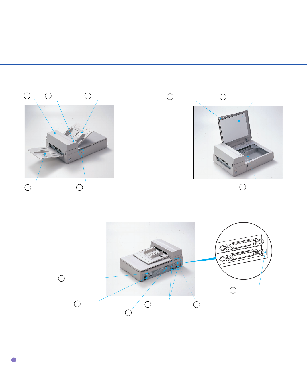
Units
1
ADF
5
Stacker
ADF lever2 ADF paper chute
3
Indicators
4
M3093DE
6
Document holding padDocument cover
7
M3093DG
8
Document bed
1-2
13
Power switch
12
Power inlet
10
11
Memory cover
Interface cable
9
Third party slot
14
Address switch
Page 15

No. Function
1
2
3
4
5
6
7
8
9
Connected to the host system with interface cables.
10
11
Automatically feeds documents to the reading position.
Opens/closes ADF to remove the jammed documents.
Holds the documents to be fed by ADF.
Indicate the status of the scanner.
Stacks the read documents.
Covers a document to be read.
Presses a document to the document bed.
A document to be read is placed. Also called Flatbed. (FB)
Third party slot (M3093DE)
Open here when installing or replacing Memory option.
DESCRIPTION
12
13
14
Connect the power cable from an AC power outlet here.
Power switch.
Used for setting SCSI-ID. (M3093DG)
1-3
Page 16
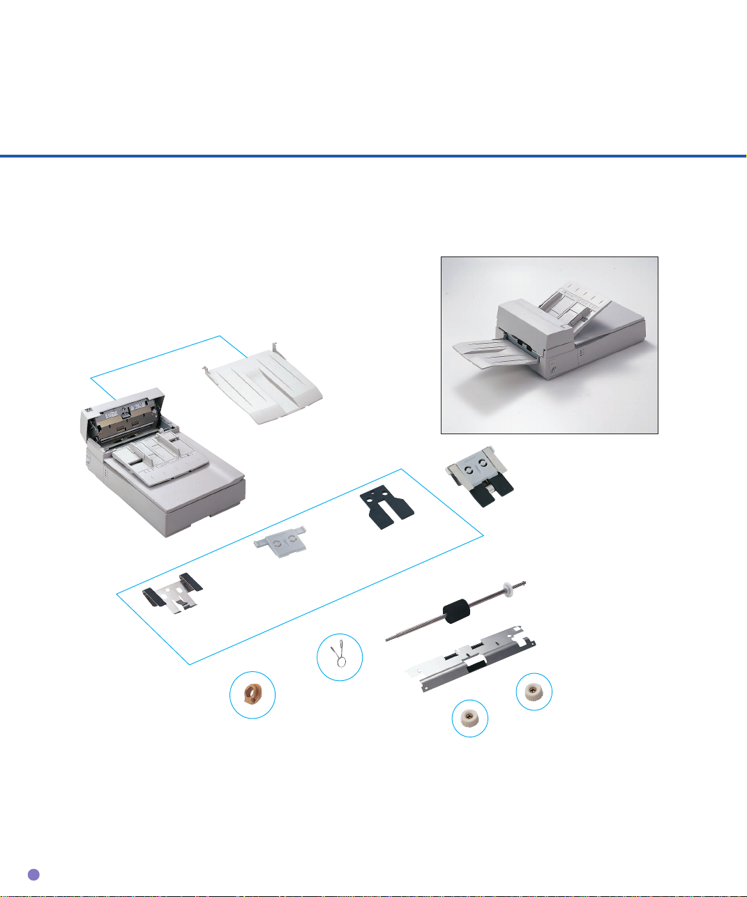
Assemblies
Stacker
*Pad ASY
(PA02201-0020)
Pad
Pad holder
**Pick roller
Pad spring
(PA02212-K001)
Guide A
Retaining
Thumb screw
spring
**:Consumables
Bearing
**:Consumables
These parts may not be provided in some countries because they are not compliant with safety
regulations. Before ordering the pick roller, contact your sales agent or Fujitsu service
representative.
1-4
Page 17
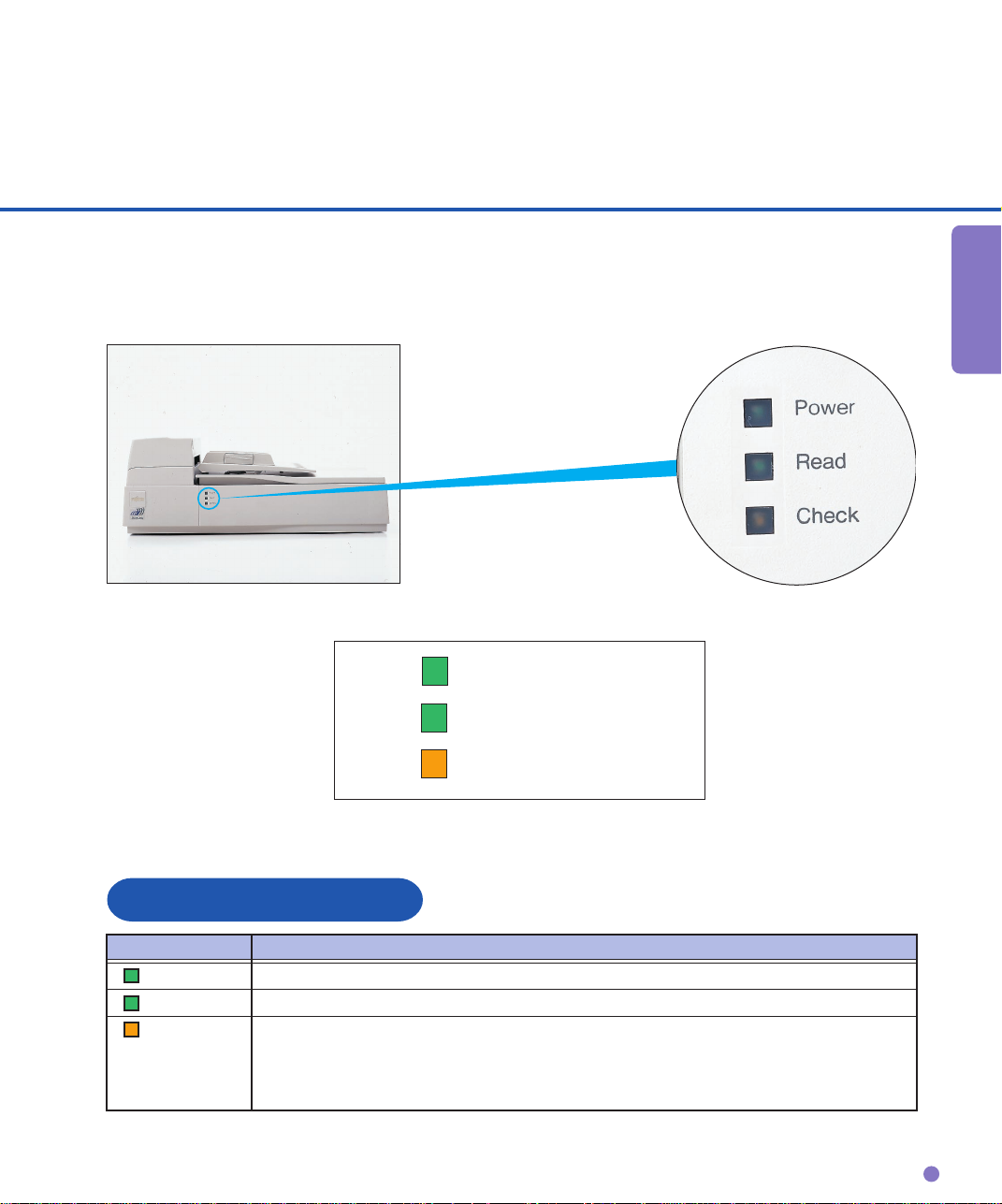
Indicators
DESCRIPTION
Power
Read
Check
LED functions
LED Function
Power Lights to indicate the power is on.
Read Lights to indicate scanning is in progress.
Check Lights if a device error occurs that may result in a service call.
Blinks if a document is jammed in the ADF. Turns off when the jammed
documents are removed from the ADF and ADF is closed. Blinks at four
seconds intervals if the ADF cleaning is necessary.
1-5
Page 18

Page 19

OPERATING
INSTRUCTION
CHAPTER
2
OPERATING INSTRUCTION
This chapter describes how to load document on the ADF and
flatbed, how to load document larger than the document board
and how to read a page from a thick book.
Loading Document on the ADF
Loading Document on the Flatbed
Loading Document Larger than the Document Board
Reading a Page from a Thick Book
2-1
Page 20
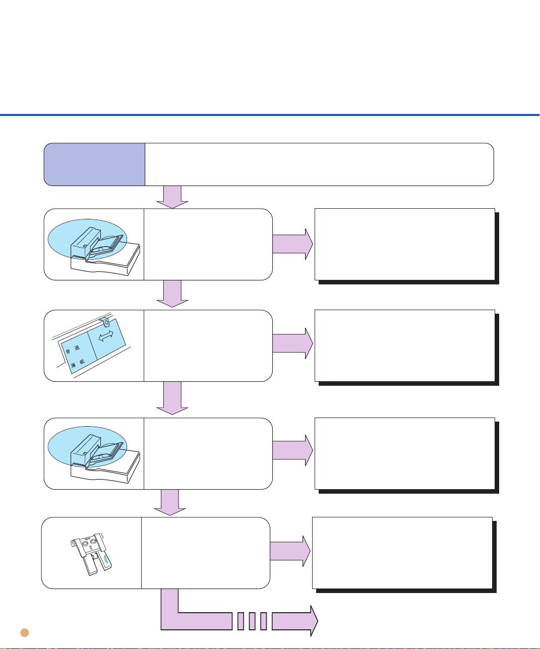
Loading Document on the ADF
1
CAUTION
Be sure to change the position of the carrier fixing bracket according to “INSTALLATION AND CONNECTION” in OPERATOR’S GUIDE before operation. This may prevent the scanner from being damaged.
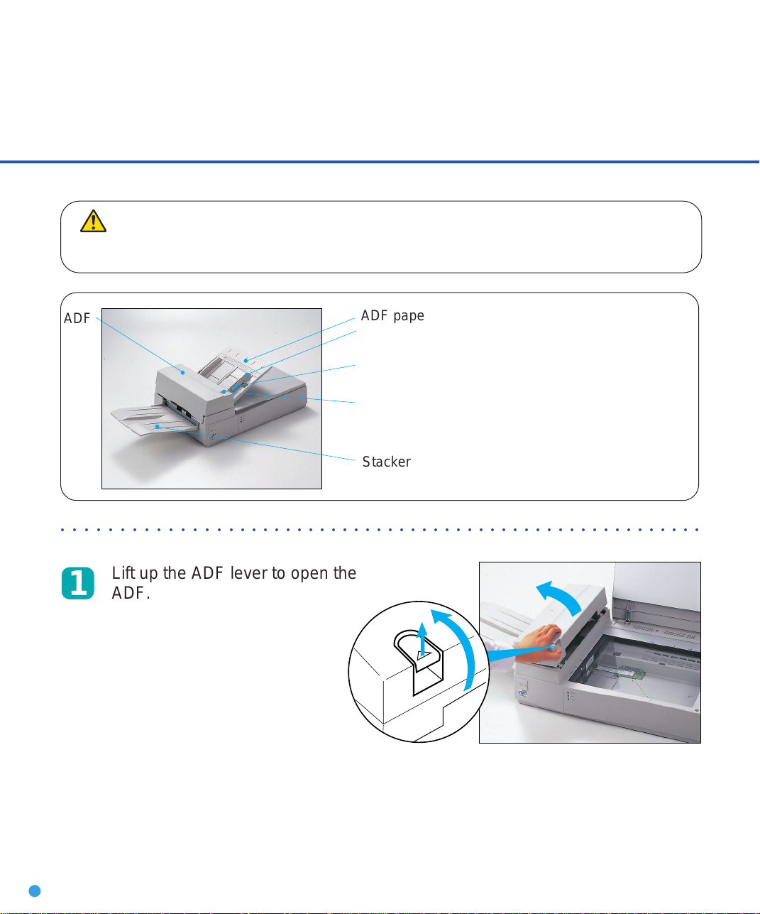
ADF
○○○○○○○○○○○○○○○○○○○○○○○○○○○○○○○○○○○○○○○○○○○○○○○○○○○○○○○○
ADF paper chute
Guide
Guide lever
ADF lever
Stacker
Lift up the ADF lever to open the
ADF.
UP
2-2
Page 21

OPERATING
INSTRUCTION
Select lever
2
Set the paper select lever as
follows.
N
N:NORMAL
T:THICK
○○○○○○○○○○○○○○○○○○○○○○○○○○○○○○○○○○○○○○○○○○○○○○○○○○○○○○○○
3
Close the ADF.
T
Paper
Plain paper
Heavy paper
NOTE
Be sure to reset the paper select lever
to “NORMAL” when you load the
paper other
than the heavy paper.
Mode
NORMAL
THICK
ADF paper chute
Pull up the ADF paper chute until
4
it clicks.
2-3
Page 22

Document
5
Fan the sheets before setting
the document on the ADF paper
chute.
NOTE
• Remove paper clips and staples. Flatten the staple
holes .
10mm
• Read the following documents using the flatbed.
- Paper with a clip or staple.
- Paper that has ink which is not dry.
- Paper thickness is not constant, such as an envelope.
- Paper that has large rumples or curl.
- Paper that has folds or tears.
- Tracing paper.
- Coating paper.
- Carbon paper.
- Paper that is smaller than A6 size or larger than A4
width.
- Items other than paper, such as clothes, metal sheet,
or OHP film.
- Photographic paper.
- Paper that has perforations on its side.
- Paper that has a shape other than square.
- Paper that is very thin.
2-4
• Set the paper so that the top of it is curled as shown
below.
More than 30mm
Less than
3mm
Top of the paper Read surface
Feed direction
More than 30mm
Less than
5mm
Top of the paper
• Do not mix different width documents.
Feed direction
Read surface
Page 23

OPERATING
INSTRUCTION
Angle the document edges as follows:
6
• Place the documents face down with the top to the left as shown in A. The long side is the top for
landscape mode and the short side is the top for portrait mode.
• Lift the documents holding the both ends with both hands.
• Hold the documents tightly with your left hand and bend the documents as shown in B.
• Grip tightly with your right hand, loosen the grip of your left hand, and straighten the documents
as shown in C.
• Repeat these operations until the top is angled 20° or less as shown in D.
Top
AB
C
B
A
D
(For portrait mode)
C
222
20 or Less
2-5
Page 24

Set the guides so that there is a
max 4mm
(0.16")
7
little amount of clearance between
the side edges and the guides.
Load the document face down on
the ADF paper chute and adjust
the guides to the document size.
NOTE
• Squeeze the guide lever to free the guides.
• Load documents so that the thickness is less than 4mm.
• Set the guides so that they touch the document sides.
Documents
Guide
○○○○○○○○○○○○○○○○○○○○○○○○○○○○○○○○○○○○○○○○○○○○○○○○○○○○○○○○
Guide lever
(Both sides)
After the read command is issued
8
from the host system, scanned
documents are stacked in the
stacker for removal.
2-6
Page 25

OPERATING
INSTRUCTION
WARNING
4
Do not look directly at the light source during read operation.
Loading Document on the Flatbed
Document cover
Document holding pad
Document bed
○○○○○○○○○○○○○○○○○○○○○○○○○○○○○○○○○○○○○○○○○○○○○○○○○○○○○○○○○○
1
○○○○○○○○○○○○○○○○○○○○○○○○○○○○○○○○○○○○○○○○○○○○○○○○○○○○○○○○○○
Open the document cover.
Reference mark
2
3
Place the document facedown and align the top left of
it with the reference mark.
Close the document cover
slowly.
Issue the read command
from the host system.
2-7
Page 26
WARNING
Do not look directly at the light source during read operation.
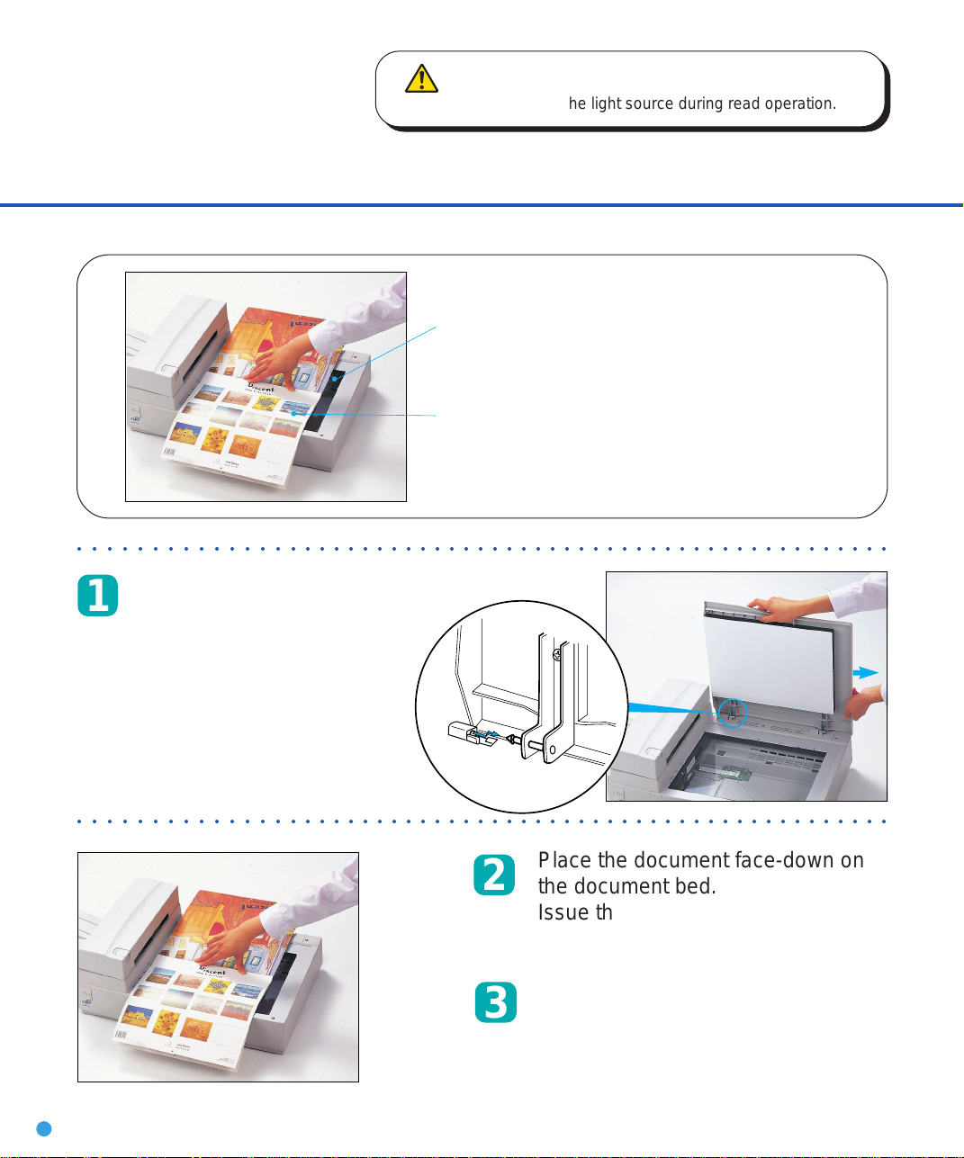
Loading Document Larger than the Document Board
Document bed
Document
○○○○○○○○○○○○○○○○○○○○○○○○○○○○○○○○○○○○○○○○○○○○○○○○○○○○○○○○
Open the document cover
1
approx. 80 degrees and slide
the cover in the direction of
the arrow to remove it.
○○○○○○○○○○○○○○○○○○○○○○○○○○○○○○○○○○○○○○○○○○○○○○○○○○○○○○○○
Place the document face-down on
2
3
2-8
the document bed.
Issue the read command from the
host system.
After the read operation, remove the
document, re-attach the document
cover and close the document
cover.
Page 27
OPERATING
INSTRUCTION
WARNING
Do not look directly at the light source during read operation.
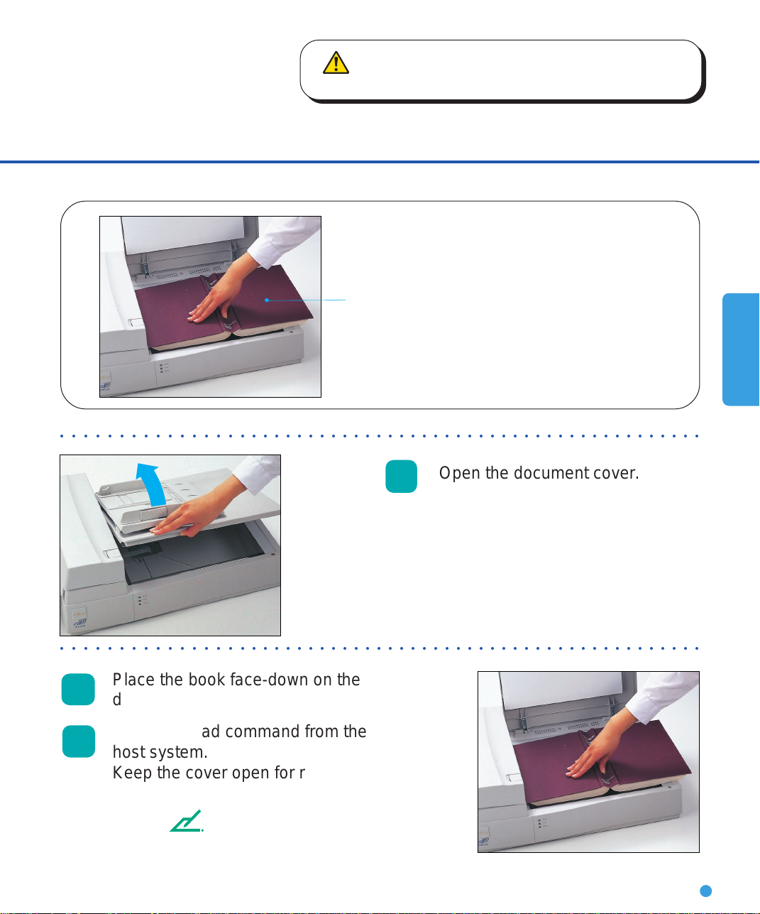
Reading a Page from a Thick Book
Thick book
○○○○○○○○○○○○○○○○○○○○○○○○○○○○○○○○○○○○○○○○○○○○○○○○○○○○○○○○
1
○○○○○○○○○○○○○○○○○○○○○○○○○○○○○○○○○○○○○○○○○○○○○○○○○○○○○○○○
Open the document cover.
Place the book face-down on the
2
document bed.
Issue the read command from the
3
host system.
Keep the cover open for reading.
NOTE
Do not move the book during read operation.
2-9
Page 28

Page 29

CLEANING
CHAPTER
3
CLEANING
This chapter describes the cleaning supplies and area, and
how to clean the ADF and flatbed.
Cleaning Supplies and Cleaning Area
Cleaning the ADF
Cleaning the Flatbed
3-1
Page 30
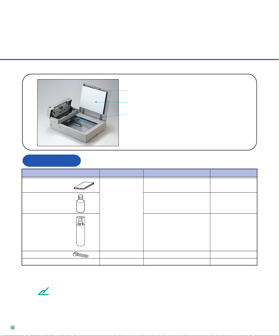
Cleaning Supplies and Cleaning Area
Document cover
Document holding pad
Document bed
Supplies
Type No. RemarksSupplies
Cleaning paper Contact your Every 5,000 sheets
dealer or
Cleaner F2 distributer • Plastic rollers (*2) 1 bottle
Cleaner F1 or • PAD ASY 1 bottle.
Isopropyl alcohol Every 5,000 sheets Apply Cleaner F1
Cotton swab
Dry cloth
*1 When the CHECK indicator starts blinking at 4-second intervals, clean the scanner regardless of the
frequencies.
*2 Clean the plastic rollers when they are soiled with dirt. Do not clean the rubber rollers with cleaner F2.
NOTE
When the following paper is used, it may be necessary to clean more frequently.
• Paper with smooth surface such as coated paper.
• Paper with almost all printed area.
• Paper with special coating such as carbon-less paper.
Frequencies (*1)
Apply Cleaner F2
to cotton swab.
• Pick roller/Feed rollers/ to cloth.
Glass/Sheet guide
Every 5,000 sheets
3-2
Page 31
CLEANING
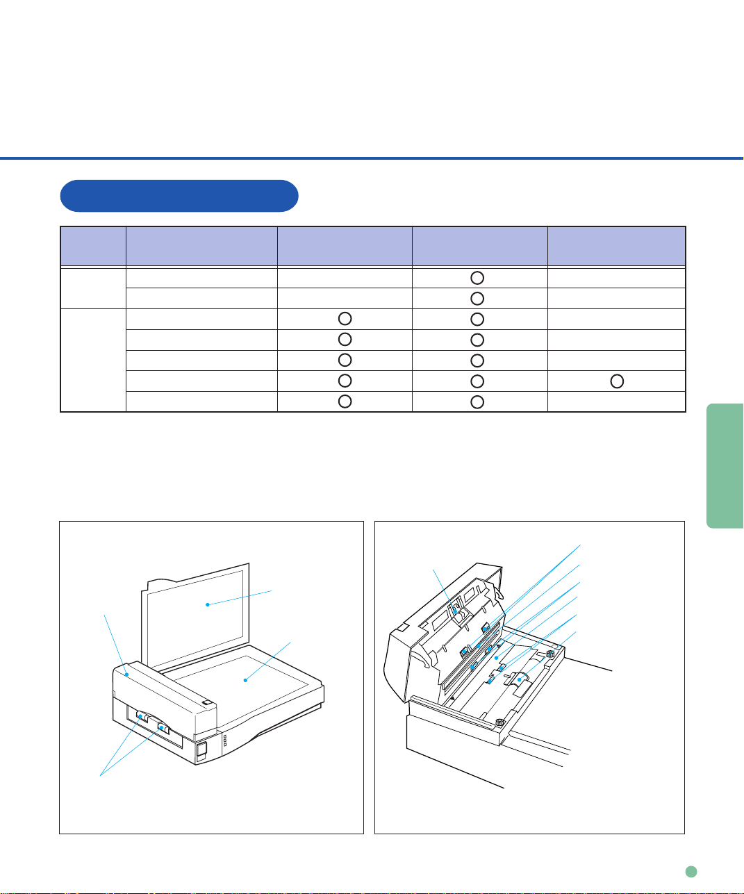
Cleaning area
Area
Flatbed
ADF
ADF
Name
Document holding pad
Document bed
Pad
Glass/Sheet guide
Pick roller
Plastic rollers
Feed rollers
Cleaning paper
with Cleaner F1
Document
holding pad
Document bed
Dry cloth
with Cleaner F1
Pad
Cotton swab
with Cleaner F1 or F2
Feed rollers
Sheet guide(White part)
Feed rollers
Glass
Plastic rollers
Pick roller
Plastic rollers
3-3
Page 32

Cleaning the ADF
pow-on
Cleaning the ADF with cleaning paper
UP
Lift up the ADF lever to open
1
2
○○○○○○○○○○○○○○○○○○○○○○○○○○○○○○○○○○○○○○○○○○○○○○○○○○○○○○○○
the ADF.
Apply cleaner F1 to a new
cleaning paper.
Cleaning
paper
○○○○○○○○○○○○○○○○○○○○○○○○○○○○○○○○○○○○○○○○○○○○○○○○○○○○○○○○○
Close the ADF and turn
4
5
6
the power on to start the
cleaning.
Turn the power off.
Repeat steps 1 through 5.
Cleaning paper
Plastic
rollers
3
Place the cleaning paper on the
ADF so that the short side edge
touches the plastic roller.
3-4
Page 33

CLEANING
Cleaning the ADF with Dry cloth with Cleaner F1
1
Lift up the ADF lever to open the ADF.
Use a dry cloth or a cloth moistened with Cleaner F1 to softly
2
remove dirt and dust as follows.
Pad
Pad
Wipe the pad in the downward
direction (indicated by the arrow).
Be careful not to hook the pick
spring when wiping.
○○○○○○○○○○○○○○○○○○○○○○○○○○○○○○○○○○○○○○○○○○○○○○○○○○○○○○○○
Glass
Wipe the glass lightly.
NOTE
If the glass is dirty, the image may include vertical
stripes.
Glass
3-5
Page 34

Plastic rollers
Pick roller
Wipe the roller.
Be careful not to damage the
surface of the roller and the
mylar strip above the Pick
roller.
Pick roller
○○○○○○○○○○○○○○○○○○○○○○○○○○○○○○○○○○○○○○○○○○○○○○○○○○○○○○○○
Feed rollers
and Plastic rollers
Wipe the rollers.
Be careful not to
damage the surface of
the rollers.
3-6
Feed rollers Plastic rollers
Page 35

CLEANING
Sheet guide (white part)
Sheet guide (white part)
Wipe the sheet
guide.
NOTE
If the sheet guide is dirty, the front image may include
vertical stripes.
○○○○○○○○○○○○○○○○○○○○○○○○○○○○○○○○○○○○○○○○○○○○○○○○○○○○○○○○
3
Close the ADF to lock the ADF lever.
3-7
Page 36

Cleaning the Plastic rollers with Cleaner F2
Plastic rollers
Plastic rollers
1
2
3
4
Lift up the ADF lever to open
the ADF.
Moisten a cotton swab with
Cleaner F2.
Wipe the Plastic roller
surfaces.
Wipe the Plastic roller
surface with clean and dry
cloth. Allow to dry.
3-8
Page 37

CLEANING
Cleaning the Flatbed
Cleaning the Flatbed with Dry cloth with Cleaner F1
Document cover
Document holding pad
Document bed
NOTE
Window or glass cleaner can be used instead of
cleaner F1.
However do not use organic solvent.
○○○○○○○○○○○○○○○○○○○○○○○○○○○○○○○○○○○○○○○○○○○○○○○○○○○○○○○○
1
Open the Document cover.
Apply Cleaner F1 to a clean cloth.
2
Wipe the document holding pad and
3
4
NOTE
Be sure to prevent liquid from seeping through the opening
between the document bed and the plastic cover.
document bed.
Allow to dry.
3-9
Page 38

REPLACEMENT
OF PARTS
CHAPTER
4
REPLACEMENT OF PARTS
This chapter describes how to replace the pad ASY, pad and
pick roller.
Pad ASY or Pad
Pick Roller
4-1
Page 39

Pad ASY or Pad
3
ADF lever
Pad ASY (PA02201-0020)
○○○○○○○○○○○○○○○○○○○○○○○○○○○○○○○○○○○○○○○○○○○○○○○○○○○○○○○○
NOTE
The life span of the pad ASY is about 100,000
sheets or one year.
The life span may be decreased by half when
carbon-less sheets are used.
Lift up the ADF lever to open
1
the ADF.
Slide the paper select
2
lever to “N”.
Select lever
N:NORMAL
T:THICK
N
T
○○○○○○○○○○○○○○○○○○○○○○○○○○○○○○○○○○○○○○○○○○○○○○○○○○○○○○○○
Slide the pad ASY to the left and
pull it toward you.
Pad ASY
4-2
Page 40

REPLACEMENT
OF PARTS
If the Pad is attached to the scanner,
5
4
you can replace the Pad according to
Pad holder
the following procedure.
a)Remove the pick spring.
b)Remove the pad from the pad holder.
c)Attach a new pad to the pad
holder and fix it with the pick spring.
NOTE
• Turn the pad upside down so that the pad
holder pin fits with the pad hole.
• Do not alter the shape of the pick spring.
• Attach the pick spring so that both ends of
the pick spring are located on the pad.
○○○○○○○○○○○○○○○○○○○○○○○○○○○○○○○○○○○○○○○○○○○○○○○○○○○○○○○○○
Pick spring
Pad
Attach the pad ASY to the ADF
until it clicks in the reverse
sequence of step 3.
NOTE
Fit the pad ASY pin with the larger hole then
slide to the right.
NOTE
Normally, set the select lever to “N”. Return the select
lever if necessary.
○○○○○○○○○○○○○○○○○○○○○○○○○○○○○○○○○○○○○○○○○○○○○○○○○○○○○○○○
Close the ADF.
6
4-3
Page 41

Pick Roller
Pick roller (PA02212-K001)
NOTE
The life span of the pick roller is about 200,000 sheets or one year.
The life span may be decreased by half when carbon-less sheets are used.
○○○○○○○○○○○○○○○○○○○○○○○○○○○○○○○○○○○○○○○○○○○○○○○○○○○○○○○○
4-4
1
2
Lift up the ADF lever to open the
ADF.
Remove the two thumb screws.
NOTE
Use a Phillips screwdriver when they are tight.
Page 42

REPLACEMENT
OF PARTS
Lift up the Guide A with both of
3
5
6
your hands and disengage the tip
from the right hole.
Then lift the right side of the cover
and remove it.
○○○○○○○○○○○○○○○○○○○○○○○○○○○○○○○○○○○○○○○○○○○○○○○○○○○○○○○○
Hold the retaining spring and
4
slide it to the roller side.
○○○○○○○○○○○○○○○○○○○○○○○○○○○○○○○○○○○○○○○○○○○○○○○○○○○○○○○○
Slide the pick roller to the retaining
spring side until the axis of the
opposite side is disengaged.
Lift and remove it.
Remove the retaining spring.
4-5
Page 43
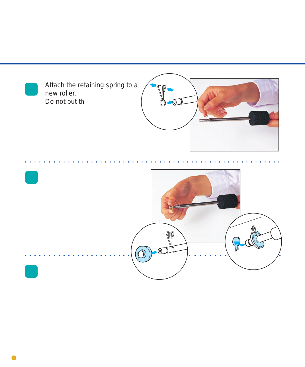
Attach the retaining spring to a
7
○○○○○○○○○○○○○○○○○○○○○○○○○○○○○○○○○○○○○○○○○○○○○○○○○○○○○○○○
new roller.
Do not put the spring in the
groove yet. Slide the spring
next to the larger diameter
portion of the shaft.
8
○○○○○○○○○○○○○○○○○○○○○○○ ○○○○○○○○
9
Slide the end of the new pick
roller with the retaining spring
into the bearing, then into the
hole closer to the front of the
scanner. Next, slide the opposite end of the pick roller into
the bearing next to the gears.
Hold the retaining spring,
slide it to the bearing slide
and place it into the groove
to fix it.
4-6
Page 44

REPLACEMENT
OF PARTS
Guide A
Attach the Guide A in the reverse
10
○○○○○○○○○○○○○○○○○○○○○○○○○○○○○○○○○○○○○○○○○○○○○○○○○○○○○○○○
sequence of step 3 and align the
screw hole.
Thumb screws
11
12
Tighten the thumb screws.
Close the ADF unit.
4-7
Page 45

Page 46

TROUBLESHOOTING
CHAPTER
5
TROUBLESHOOTING
This chapter describes the paper JAM, initial checks and test mode
for maintenance.
Paper JAM
Initial Checks
Test Mode for Maintenance
Problem Checklist
TROUBLESHOOTING
5-1
Page 47

Paper JAM
Document
ADF
ADF lever
○○○○○○○○○○○○○○○○○○○○○○○○○○○○○○○○○○○○○○○○○○○○○○○○○○○○○○○○○
Remove the documents from
1
the ADF paper chute.
2
3
Inspect the paper and paper path. Make sure no staples,
paper clips or other materials caused the jam. All types of
staples and paper clips should be removed from all
documents bofore scanning.
4
5-2
Lift the ADF lever to open the ADF.
Remove the jammed document.
NOTE
Close the ADF until the ADF lever
locks.
Page 48

TROUBLESHOOTING
Initial Checks
If a problem occurs, check the following items before contacting manufacturer’s authorized
service center.
Symptom1
The power does not go on. Power
Is the power cable
connected correctly?
YES
Is the power switch on?
YES
Contact manufacturer’s authorized
service center.
(No light)
NO
Connect the power
cable correctly.
NO
Press the power switch.
TROUBLESHOOTING
5-3
Page 49

Symptom2
Read operation does not start.
Is the carrier fixing
bracked placed in
operation position?
YES
Are the documents
loaded on the ADF
paper chute correctly?
YES
Is the ADF closed
completely?
YES
Is the interface cable
connected correctly?
NO
NO
NO
NO
Place the carrier fixing
bracket correctly.
(See Operator’s Guide)
Insert the first few pages into
the slot.
Close the ADF completely.
Connect the interface cables
correctly.
5-4
YES
Page 50

TROUBLESHOOTING
Is the terminator connected? Is the SCSI ID
is set correctly?
(M3093DG)
YES
NO
Connect the terminator or
set the SCSI ID correctly.
Is the baud rate of the
system 4800 bps?
(Default is 4800 bps.)
YES
Check
Is the CHECK indicator
lit?
NO
Contact manufacturer’s authorized
service center.
NO
YES
Contact manufacturer’s
authorized service center to
set correct baud rate.
Refer to Symptom 6.
(See p5-9)
TROUBLESHOOTING
5-5
Page 51

Symptom3
Pictures and photographs are not read correctly.
Is the “Photo” mode
selected?
YES
Is halftone or dithering
processing selected?
YES
Is the document bed,
document holding pad,
glass and sheet guide
clean?
YES
NO
NO
NO
Select the “Photo” mode
(White level following off)
through the scanner setting
menu in the software.
Select a halftone or dithering
mode from the host computer.
Clean the dirty parts.
(See p3-5, p3-7, p3-9)
Contact manufacturer’s authorized
service center.
5-6
Page 52

TROUBLESHOOTING
Symptom4
Characters and lines are not read correctly.
NO
Is the “Line Art” mode
selected?
Select a “Line Art” mode from
the host computer.
YES
3mm
Is there printed text on
the first 3mm of the
document?
NO
Is the document bed,
document holding pad,
glass and sheet guide
clean?
YES
Contact manufacturer’s authorized
service center.
YES
NO
Select the “Photo” mode
(White level following off)
via software.
Clean the dirty parts.
(See p3-5, p3-7, p3-9)
TROUBLESHOOTING
5-7
Page 53

Symptom5
Images are distorted or unclear.
missing
Is the document bed,
document holding pad,
glass and sheet guide
clean?
YES
Is the surface of the ADF
pressed or is there
anything heavy on it?
(During rear read operation with ADF)
NO
Is the scanner on
even and flat surface
or any scanner rubber
feet missing?
YES
NO
YES
NO
Clean the dirty parts.
(See p3-5, p3-7, p3-9)
Do not press the surface of
the ADF or do not put anything heavy on it.
Place the scanner on the
even and flat surface.
Or attach the rubber feet.
Contact manufacturer’s authorized
service center.
5-8
Page 54

TROUBLESHOOTING
Symptom6
The check indicator is on.
Check
Is the carrier fixing
bracket placed in
operation position?
YES
Turn off the power once
and try to turn on the
Check
power again.
Is the CHECK lamp
turned on?
YES
Activate the test mode (p5-17) and
inform manufacture’s authorized
service center of the error status.
NO
Place the carrier
fixing bracket correctly.
(See Operator’s Guide)
TROUBLESHOOTING
5-9
Page 55

Symptom7
“Check” lamp blinks at 4 seconds intervals.
YES
Check
Is the pick roller dirty?
NO
Are documents under
specification?
(See p5-11)
YES
Is the Pad ASY dirty or
worn out?
NO
Clean the pick roller.
NO
Flatten the curl or use the
flatbed to read the document.
YES
Clean or replace the Pad ASY.
(See p3-4, p3-5, p4-2)
5-10
Contact manufacturer’s authorized
service center.
Page 56

TROUBLESHOOTING
NOTES
NOTE
• Remove paper clips and staples. Flatten the staple holes.
• Read the following documents using the flatbed.
- Paper with a clip or staple.
- Paper that has ink which is not dry.
- Paper thickness is not constant, such as an envelope.
- Paper that has large rumples or curl.
- Paper that has folds or tears.
- Tracing paper.
- Coating paper.
- Carbon paper.
- Paper that is smaller than A6 size or larger than A4 width.
- Items other than paper, such as clothes, metal sheet, or OHP film.
- Photographic paper.
- Paper that has perforations on its side.
- Paper that has a shape other than square.
- Paper that is very thin.
• Set the paper so that the top of it is curled as shown below.
Less than
3mm
• Do not mix different width documents.
More than 30mm
Top of the paper Read surface
Feed direction
More than 30mm
Less than
5mm
Top of the paper
Feed direction
Read surface
TROUBLESHOOTING
5-11
Page 57

Symptom8
Paper double feed occurs frequently.
N:NORMAL
T:THICK
Does the condition of
the document satisfy
the requirements on
page 5-11.
NO
Flatten the curl or use the
flatbed to read the document.
YES
N
T
Is the plain paper read
with the select lever set
to “T”?
YES
Set the select lever to “N”.
(See p2-3)
NO
Are the documents
fanned and angled before
loading on the ADF paper
chute?
NO
Fan and angle the documents
before loading according to
the procedure on the pages
2-3 and 2-4.
YES
5-12
Is the paper printed by
copier or laser printer
recentry?
NO
YES
Fan 3 or 4 times to remove
the static charge applied on
paper.
Page 58
TROUBLESHOOTING
Is the height of
document less than
0.16” (4mm)?
YES
NO
Reduce the document from
ADF paper chute.
(See p2-6)
YES
Is the pad dirty?
NO
Is the pad worn out?
NO
Contact manufacturer’s authorized
service center.
Clean the pad.
(See p3-4,p3-5)
YES
Replace the pad.
(See p4-2)
TROUBLESHOOTING
5-13
Page 59
Symptom9
Miss pick occurs frequently.
N:NORMAL
T:THICK
Does the condition of
the document satisfy
the requirements on
page 5-11.
NO
Flatten the curl or use the
flatbed to read the document.
YES
YES
N
T
Is the heavy paper read
with the select lever set to
“N”?
Set the select lever to “T”.
(See p2-3)
NO
Are the documents
fanned and angled before
loading on the ADF paper
chute?
NO
Fan and angle the documents
before loading according to
the procedure on the pages
2-3 and 2-4.
YES
5-14
Is the Pad ASY installed
correctly?
YES
NO
Install it correctly.
(See p4-2)
Page 60

TROUBLESHOOTING
YES
Is the pick roller dirty?
NO
Is the pick roller worn
out?
NO
Contact manufacturer’s authorized
service center.
Clean the pick roller.
(See p3-4, p3-6)
YES
Replace the pick roller.
(See p4-4)
TROUBLESHOOTING
5-15
Page 61

Symptom10
Paper jam occurs frequently.
Does the condition of
the document satisfy
the requirements on
page 5-11.
NO
Is there any foreign
particles in the ADF?
NO
Contact manufacturer’s authorized
service center.
YES
Flatten the curl or use the
flatbed to read the document.
YES
Clean the ADF (See p3-4) or
remove the foreign particles.
5-16
Page 62
TROUBLESHOOTING
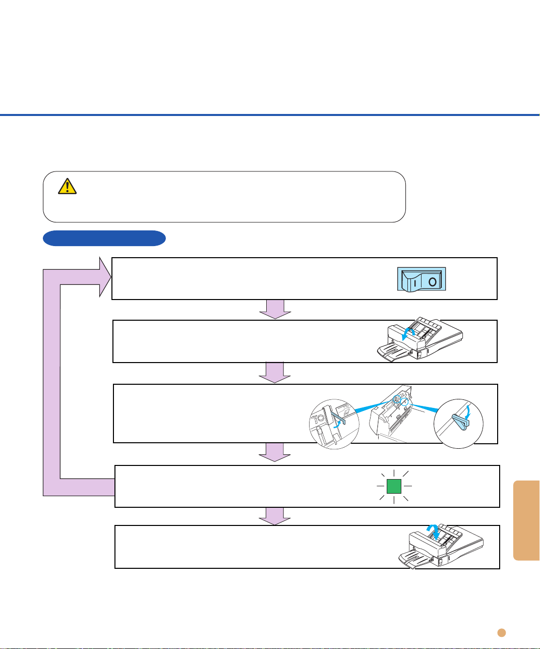
Test Mode for Maintenance
Power
If the CHECK indicator lights up, activate the test mode and inform your sales or
support agent or Fujitsu service representative of the error status.
CAUTION
If an operation other than described here is performed, the scanner may malfunction.
Activate the test mode and follow the procedure only for the error status.
Activating a test mode
Turn off the power.
Open the ADF.
Try again (*1)
Turn the power on after setting
Empty sensor B5 Size sensor
the empty sensor and B5 size
sensor as shown in the figure.
Up
NO
Does the POWER lamp blinks?
YES
Close the ADF cover.
(The scanner is placed in the maintenance mode.)
*1 Do not perform any other operation this time. Immediately turn the power off when the POWER
lamp does not blink.
Down
TROUBLESHOOTING
5-17
Page 63
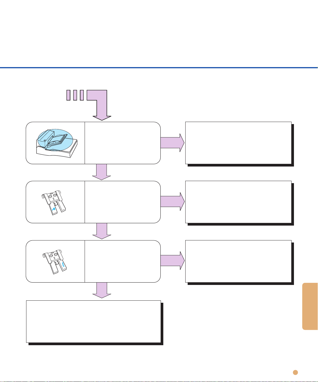
Activating the continuous operation test
Open the ADF and close it again. If no document is loaded on the ADF within five seconds after
closing the ADF, the image scanner runs in flatbed mode. If documents are loaded on the ADF
within five seconds after closing the ADF, the image scanner continuously feeds the document
from ADF. Once the image scanner starts reading documents in flatbed mode, it does not feed
documents from ADF even if documents are loaded on the ADF.
Ending the test in flatbed mode
To stop the carrier movement in flatbed mode, open the ADF. If the ADF is opened, the POWER
lamp starts blinking immediately after the carrier returns to the home position.
Ending the test in ADF mode
If the ADF hopper is empty, feeding documents from the ADF ends. To restart feeding, open the
ADF and close it again. Then load documents on the ADF paper chute within five seconds after
closing the ADF.
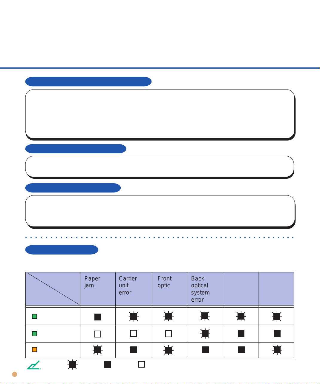
○○○○○○○○○○○○○○○○○○○○○○○○○○○○○○○○○○○○○○○○○○○○○○○○○○○○○○○○
LED status on error
If an error occurs during the test, the LED indicates as shown in the following table.
Motor
fuse
failure
Lamp
fuse
failure
LED
indicates
NOTE
5-18
Power
Read
Check
Errors
Status
Paper
jam
Carrier
unit
error
Blink On Off
Front
optical
system
error
Back
optical
system
error
Page 64

TROUBLESHOOTING
Problem Checklist
Before contacting the manufacture’s authorized service center, please fill in the following items.
General
Model
Part number
Serial number
Manufactured data
Version
A
0
123456789
B
0
123456789
C
0123456789
Date of purchase
Symptoms
Persistent problem?
Serviced before (when and how)?
Error status at test mode. (See p5-18)
Transport error
Type of document.
What is your daily usage?
Date of last cleaning.
Date of the consumable replacement.
(Example) M3093DE
(Example) CA02939-4202
(Example) 900002
(Example) 1996-07
The version is printed on the version label
located at the left of the rear of the equipment.
The version is checked with the double line.
This example is for A2 version.
Image error
Interface controller model
Software/application name
Can you send the original and output of
sheet by facsimile or by mail?
TROUBLESHOOTING
5-19
Page 65

 Loading...