

Page 1

M304X
SERIES LINE PRINTER
OEM MANUAL
Page 2

Page 3
r
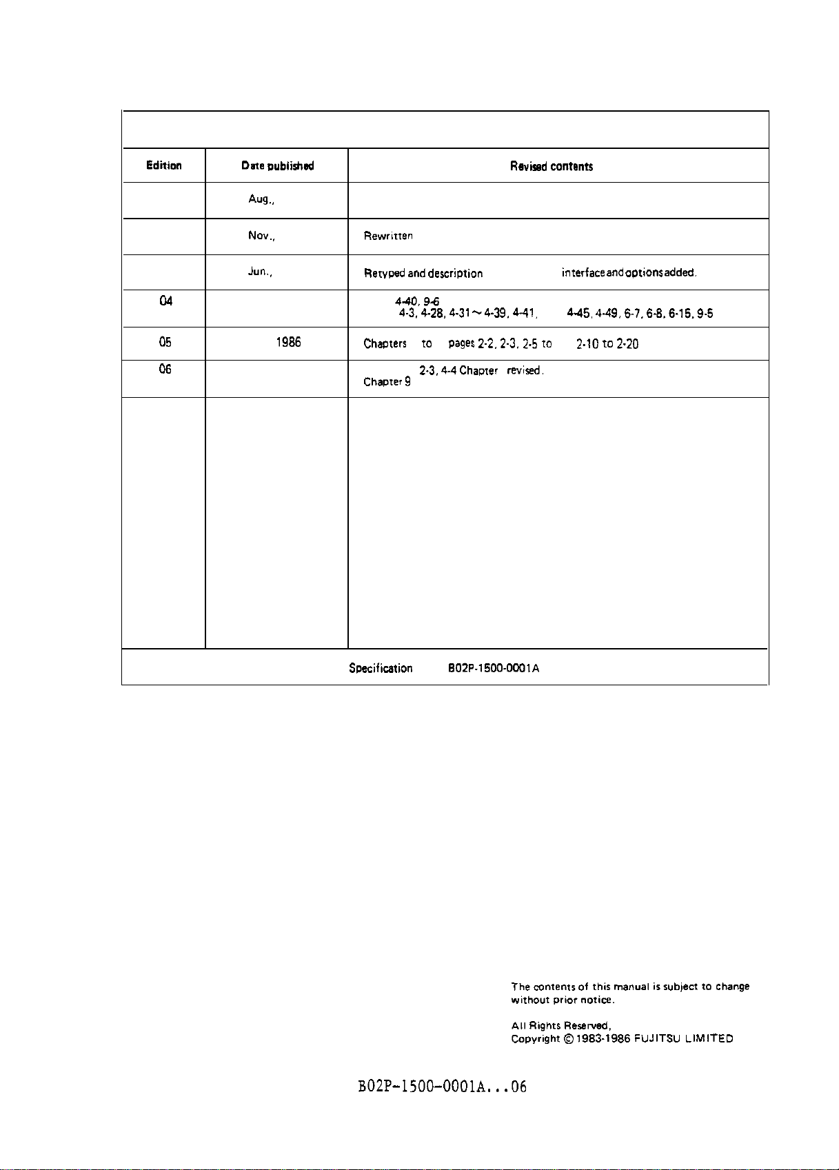
REVISION RECORD
Edition
01
02
03
04
05 Jun., 1986
06
Dam Lwblishd
*ug.,
No”..
.I”“.. 1985
Aug.,
Nov., 1986
1983
1984
1985
f3ewritren
Rer”ped and dePCripti.3”
Pager
440.96
Pager
Cha,xerr 4 to 9.
Pager
: Chacmr9 deleted.
4-3.4-28.4-31
2-3.44
added
pages 2-2.2.3.
Revised Content$
Of. RS-232-C
-4-39.441.
2.6 10 2-8. 2.10 to 2-20 reused.
Chamerand 8 revised.
interfact! and aprionr added.
442, 4.46.
449.6-7.6-8.6.16.9-6
modified
Swcification
N O .: 802P.1500.OOOIA
BOZP-ISOO-OOOlA...06
i
Page 4
FWITS” LlMlTED
In1er”atim.l
Marketing
FUJITSU NORDIC A8
lndunrigatan 2A
MaN”O”di l-s-1. Chiyoda-k”. Tokyo 100.m.PAN TEL: 8.231125
TEL 03.216-3211
FAX: 03-213-7174.03-218-9353 TLX:
TLX:
,229s
Cable: “FUJITSU LlMlTED TOKYO”
FAX: 8.106865
13411
FUJITSU ITALlA
“ia Lalzaro”i. 4. 20124
FUJITSU AMERICA INC. TEL:
3055
Orchard Drive. San
TEL: 408.9468777
,ore.
California
951342017. U.S.A.
FAX: 2-688-6637
TLX: 350142
139.21 607-3601
FAX: 408-945-131*
TLX: 230-176207
TWX:
I9101
338-2193
FUJITSU CANADA INC.
6260 Northwen
TEL:
114161
Drive.
6734666
FAX: 416.673-8677
TLX: 968132
FUJITSSU
Roy., Trurr
EUROPE LlMlTED
House.
54
Misksaqa. Taronro. Ontario. CANADA
Jermyn
Street. London
S.W.1,
ENGLAND TLX:
FUJITSU AUSTRALIA LIMITED
4-l
McLaren
TEL:
Street. North Syd”ey, N.S.W.
161-2,
95943555
FAX: 2-922-2653
TM:
25233
FUJlTS” HONG KONG LIMITED
R.M.
1831.
Sun Hung
(852.51
TEL:
8915780
FAX: 5-742917
62667
TEL: W-1 I4084043
FAX:
1.629-9826
TLX: 263871
Plan 7. 112 46 Sroctholm. SWEDEN
S&A.
rdibano.
ITALY
2060,
AUSTRALIA
Kai
Came. 30 Harbur
Road.
HONG KONG
FVJITS” DEUTSCHLAND
RorenheimetaraBe
TEL:
149.89,
145. D-8000
413010
FAX: 8941301100
TLX: 5213994
ii
GmbH
MCinchsn 80.
F.R. GERMANY
BOZP-1500-OOOlA...06
Page 5
CONTENTS
CHAPTER
1.1
CHAPTER 2
2.1
2.2
2.3
2.4
2.5
2.5.1
2.5.2
2.5.3
2.5.4
2.5.5
2.6
2.6.1
2.6.2
CHAPTER 3
3.1
3.2 Control Unit
CHAPTER 4
4.1
4.2
4.2.1
4.2.2
4.3
4.3.1
4.3.2
4.4
4.4.1
4.4.2
4.4.3
INTRODUCTION ...............................................
1
Introduction
SPECIFICATIONS .............................................
Printer Specifications .........................................
Ribbon Specifications
Installation Conditions
Optional Unit
Forms Specification
General note about forms
Dimensions
Multiple-part forms
Ambient conditions for forms ............................... 2 - 18
Purchase order for forms
Format Control Tape
Medium quality
Dimensions
CONFIGURATION
Mechanical Unit ................................................
DPC-COMPATIBLE INTERFACE
Operation Outline ..............................................
Interface Signals
Interface signal lines
Physical specifications of interface signals
Character and Control Codes
Character codes ............................................
Control codes
Format
control
Definition of the top of forms
of form
Specification of a forms feed format
Skip and Space commands
l-l
...................................................
..........................................
........................................
..................................................
............................................
...................................
.................................................
........................................
...................................
(FCT)
.............................................
.................................................
.............................................. 3 - 1
...................................................
..............................................
..............................................
.................................................
(BOF)
..............................................
......................................
...................................
.....................................
...............
....................................
(TOF)
and the bottom
.......................
....................................
l-l
2-l
2 - 1
2-3
2-3
2-6
2 - 11
2 - 11
2 - 12
2 - 15
2 - 18
2 - 19
2 - 19
2 - 19
3-2
3-3
4-l
4-l
4-2
4-2
4-6
4-a
4 - 10
4 - 10
4 - 11
4 - 11
4- 12
4 - 19
CHAPTER 5
5.1
5.2
5.2.1
5.2.2
5.3
5.3.1
5.3.2
5.4 Format Control
5.4.1
5.4.2
5.4.3
5.5
5.5.1
5.5.2
CENTRONICS-COKPATIBLE
Operation Outline
Interface Signals
Interface signal lines
Physical specifications of interface signals
Character and Control Codes
Character codes
Control codes
Loading from the mainframe to the VFU
Loading from an FCT to the VFU
Format specification from the operator panel
VFU Commands
n-Line Skip command
Skip to Channel-n commands
................................................... 5 - 17
5
INTERFACE
..............................................
..............................................
.....................................
....................................
............................................
..............................................
.................................................
........................................
B02P-1500-OOOlA...05
............................
...............
......................
.............................
,,
..............
.................................
- 1
5-l
5-2
5-2
5-a
5 - 11
5 - 12
5 - 12
5 - 14
5 - 15
5 - 16
5 - 16
5 - 17
5 - 18
.
13.1
Page 6
CHAPTER 6
6.1
6.2
Operation Outline ..............................................
Interface Signals ..............................................
6.2.1
6.2.2
6.3
Character and Control Codes ....................................
6.3.1
6.3.2
6.4
Hessage Protocols ..............................................
6.4.1
6.4.2
6.4.3
6.4.4
6.5
6.6
Commands .......................................................
Printer Status .................................................
RS-232-C INTERFACE .........................................
6-1
6-1
6 - 4
Interface signal lines .....................................
Physical specifications of interface signals
...............
6-4
6-8
6 - 14
Character codes
............................................
6 - 16
Control codes .............................................. 6 - 16
6 - 19
XON/XOFF protocol .......................................... 6 - 19
Reverse Channel line protocol ..............................
DTR line protocol ..........................................
RTS line protocol
..........................................
6 - 19
6 - 20
6 - 20
6 - 21
6 - 28
CHAPTER 7
7.1
7.2
7.3
CRAPTER
8.1
8.2
a.3
a.4
Standard Print Band List .......................................
Standard Character Sets
Type Catalog
8
Print Bands .................................................... 8 - 2
Options ..............................................
Expendable Supplies ............................................
Special Tools ..................................................
PRIYT BAND SPECIFICATIONS
..................................
7-1
7-2
........................................
...................................................
SPECIFICATION LIST .........................................
.
..........
7-2
i-9
a-
8-3
1
8-3
a-3
iv
B02P-1500-OOOlA...06
Page 7
ILLUSTRATIONS
Figure 1.1
Figure 2.1
Figure 2.2
Figure 2.3
Figure
Figure 2.5
Figure 2.6
Figure 2.7
Figure 2.8
Figure 2.9
Figure 2.10
Figure 2.11
Figure 2.12
Lgure
Figure 2.14
Figure 2.15
Figure 2.16
Figure 2.17
Figure 2.18
Figure 2.19
2.L
2.13
M304x series line printer
Outer dimensions (with the forms rack)
Operation and maintenance area (with the forms rack)
Outer dimensions (with the powered stacker)
Operation and maintenance areas (with the
powered stacker)
FCT unit
Paper puller
Forms
Curled
Forms container lids .....................................
Shape of the forms container
Leftmost and rightmost print positions
Dimensions relating to pin feed holes
Protrusion and separation of the outer layer at the
perforation of multiple-part forms
Methods of fastening paper
Allowable incorrect alignment of multiple-pzrt forms
Multi-part forms with layers of different
Carbon paper covering pin feed holes
Self-adhesive
Specifications of FCT
.................................................
....................................................
forms
.........................................
.............................................
............................................. 2 - 11
lable
forms ................................
. . . . . . . . . . . . . . . . . . . . . . . . . . . . . . . .
...................
....
..............
.............................
...................2 -
....................
.......................
............................... 2 - 15
.....2 -
th:ickness
.....................
.................................... 2 - 20
......2 -
1- 2
2-4
2-5
2-7
2-8
2-9
2 - 10
2 - 11
2 - 12
2 - 12
13
2 - 13
2 - 14
16
17
2 - 17
2 - 18
Figure 3.1
Figure 3.2
Figure 4.1
Figure 4.2
Figure 4.3
Figure 4.4
Figure 4.5
Figure 4.6
.igure
Figure 4.8
Figure 4.9
Figure 4.10
Figure 4.11
Figure 4.12
Figure 5.1
Figure 5.2
Figure 5.3
Figure 5.4
Figure 5.5
Figure 5.6
Figure 5.7
Figure 5.8
4.7
Printer configuration ....................................
Control unit
Basic operations .........................................
Print operation
Basic data transfer operation
Timing of signals in data transfer
DPC-compatible interface signal driver and
DPC-compatible interface connector pin
(Alup type)
DPC-compatible interface connector pin assignment
(Winchester type)
Timing of FCB data loading ............................... 4 - 12
Correspondence between FCB data channels and bits
Channels specified for a forms feed format
An example of FCT and forms feed format
An example of format specification from
the operator panel .......................................
Basic operations
Character code transfer timing
Control code receive timing
DC1 code receive timing chart
DC3 code receive timing
Skip-15-Lines command receive timing chart
VFU
data receive timing chart
Centronics-compatible interface signal
.............................................
..........................................
............................
.......................
rseceiver ......4 -
assig:nment
................................................
........................................
........
...............
..................
.........................................
...........................
..............................
............................
..................................
...............5 -
............................
driver/rec.eiver
...
3 - 1
3-4
4-l
4-2
4-5
4-5
6
4-7
4-8
4 - 13
4 - 15
4 - 17
4 - 19
5-l
5 - 5
5-5
5 - 6
5-7
7
5
-8
5 - 9
BOZP-1500-OOOlA...05
"
Page 8
Figure 5.9
Figure 5.10
Centronics-compatible interface connector pin
assignment
Loading the data in the VFU
. . . . . . . . . . . . . . . . . . . . . . . . . . . . . . . . . . . . . . . . . . . . . . .
. . . . ..*.......................
5 - 10
5 - 15
Figure 6.1
Figure 6.2
Figure 6.3
Figure 6.4
Figure 6.5
Figure 6.6
Figure 6.7
Figure 6.8
Figure 6.9
Figure 6.10
RS-232-C interface circuit
RS-232-C interface signal transmitter and receiver . . . . . . . 6
Reverse channel line-protocol
(Drop DTR in START/STOP mode)
Reverse channel line-protocol (DTR Constant
XON/XOFF protocol (Drop DTR in START/STOP mode and
Half-auplex mode)
XON/XOFF protocol (Drop DTR in START/STOP mode and
Full-auplex
DTR line protocol
RTS line protocol (Drop DTR in START/STOP mode) . . . . . . . . . . 6
Interface cable connector
RS-232-C interface connector pin assignment . . . . . . . . . . . . . . 6
mode)
. . . . . . . . . . . . . . . . . . . . . . . . . . . . ..*.........
. . . . . . . . . . . . . . . . . . . . . . . . . . . . . . . . . . . . . . . .
. . . . . . . . . . . . . . . . . . . . . . . . . . . . . . . . . . . . . . . .
..*............................
. . . . . . . . . . . . . . . . ..*.........
On
mode) . . . . . 6
. . . . . . . ..*......................
6-2
-
8
6 - 10
- 10
6 - 11
6 - 11
6 - 12
-
12
6 - 13
-'14
vi
B02P-1500-OOOlA...O5
Page 9
TABLES
Table 2.1
Table 2.2
Table 2.3
Table 2.4
Table 2.5
Table 2.6
Table 2.7
Table 2.8
Table 4.1
Table 4.2
Table 4.3
Table 4.4
Table 4.5
Table 4.6
Able 4.7
Table 5.1
Table 5.2
Table 5.3
Table 5.4
Table 6.1
Table 6.2
Table 6.3
Table 6.4
stable
Table 6.6
6.5
Printer specifications
Ribbon specifications
Electrical specifications
Environmental conditions
Powered stacker specifications
FCT unit specifications
Perforation dimensions ....................................
Recommended bond weight of forms
DPC-compatible interface signal lines (Positive logic)
Character (ASCII) and control codes
Definition of the start code
VFU data example
Skip commands ............................................. 4 - 20
Space commands
Space commands
Centronics-compatible interface signal lines
Character (ASCII) and control codes
n-line Skip commands
Skip to Channel-n commands ................................
RS-232-C interface signal lines
Operation by the RTS and CTS combination
Printer statuses
Character (ASCII) and control codes
Commands and their control sequences
Printer status
..........................................
(15-line
(63-line
.......................................... 6 -
............................................ 6 - 28
.................................... 2-2
.....................................
.................................
.................................. 2 - 6
............................
...................................
..........................2 - 16
....
.......................4 -
...............................
feed mode)
feed mode)
......................................
........................
........................
.............. 5 - 3
.......................5 -
...........................
..................
.......................6 -
......................6 -
2 - 3
2-3
2 - 6
2-9
2 - 14
4 - 3
4 - 13
4 - 16
4 - 21
4 - 21
5 - 17
6 - 1
6-7
9
11
5 - 18
9
15
21
B02P-1500-OOOlA...05 vii
Page 10

Page 11
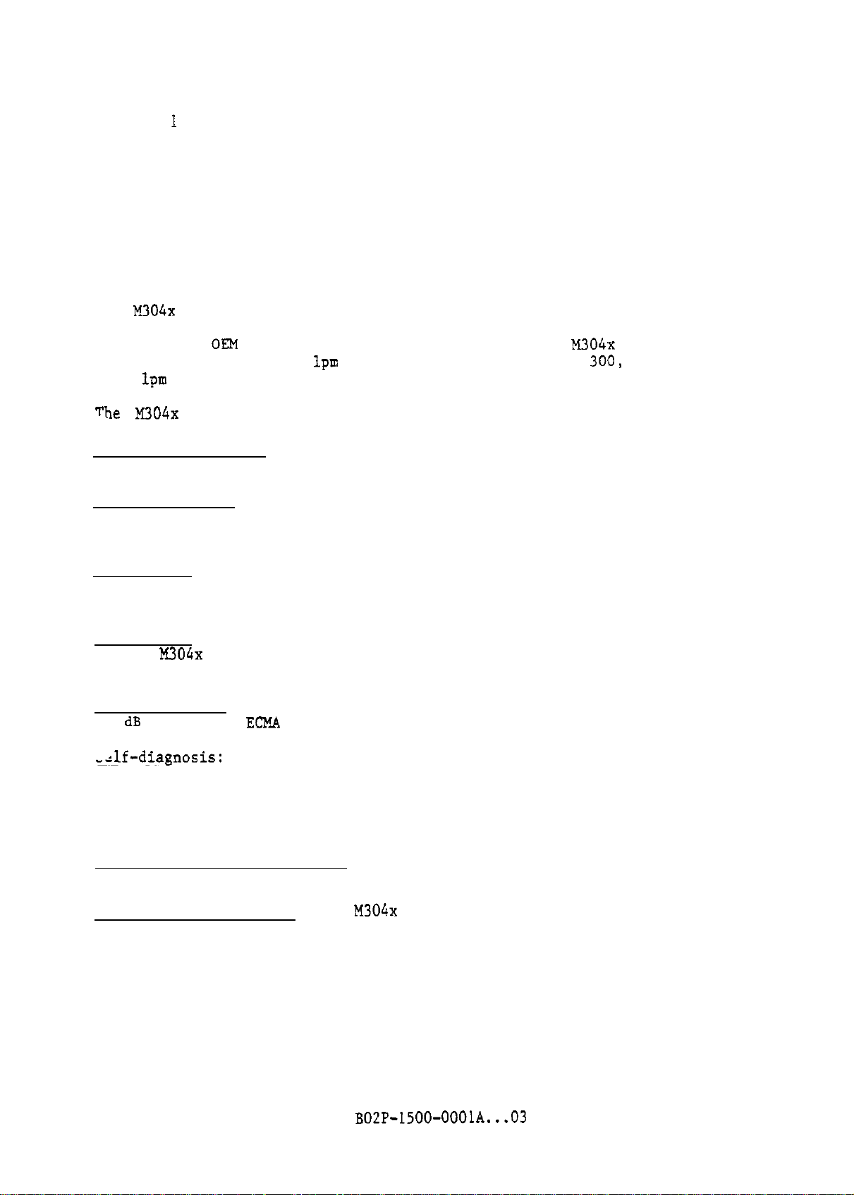
CHAPTER 1 INTRODUCTION
1.1 Introduction
The
M304x
series (M3040, M3041, M3042, and M3043) is Fujitsu's latest
introduction of highly cost-effective line printers using a print band and
designed for OKM applications. The printing speeds of
390, 750, 1090, and 1420
1200
The
lpm
for a 64-character set respectively.
M304x series provides the following features:
lpm
for a 48-character set, and
M304:x
3013,
series models are
600, 900, and
Superb Print-quality:
up to six-part forms.
High Reliability_: By using simplified mechanical design, reduced adjustment
requirements,
guaranteed.
compactness:
unit is controlled by microprocessors, operability has be improved and printer
size has been reduced,
Commonality:
in all M304x series models, minimizing parts inventory and reducing maintenance
training costs.
Low Sound Level:
55 dB A (in the
-zlf-diagnosis:
diagnosis is performed immediately after power-on.
automatically indicated, enabling the operator to determine if the error is
operator-correctable or requires customer engineer service.
can also test printers offline.
and self-diagnosis function, high reliability is consistently
Since the mechanical unit is divided into modules and control
Almost all mechanical and electric components are used in common
By using a soundproofing structure, a sound pressure level of
ECM@.
Thanks to the incorporation of microprocessors and sensors,
Improved print hammers assure excellent print quality on
resulting in compact installation space.
condition) has been attained for all models.
Errors during printing are
The microprocessor
Simple Print Band Interchange: Each printer can use up to four print band;
three standard ones,
Wide Variety of Options:
individual customer needs
and one optional one.
M304x
The
B02P-1500-OOOlA...03
series offers
a variety
of
options to meet
l-l
Page 12
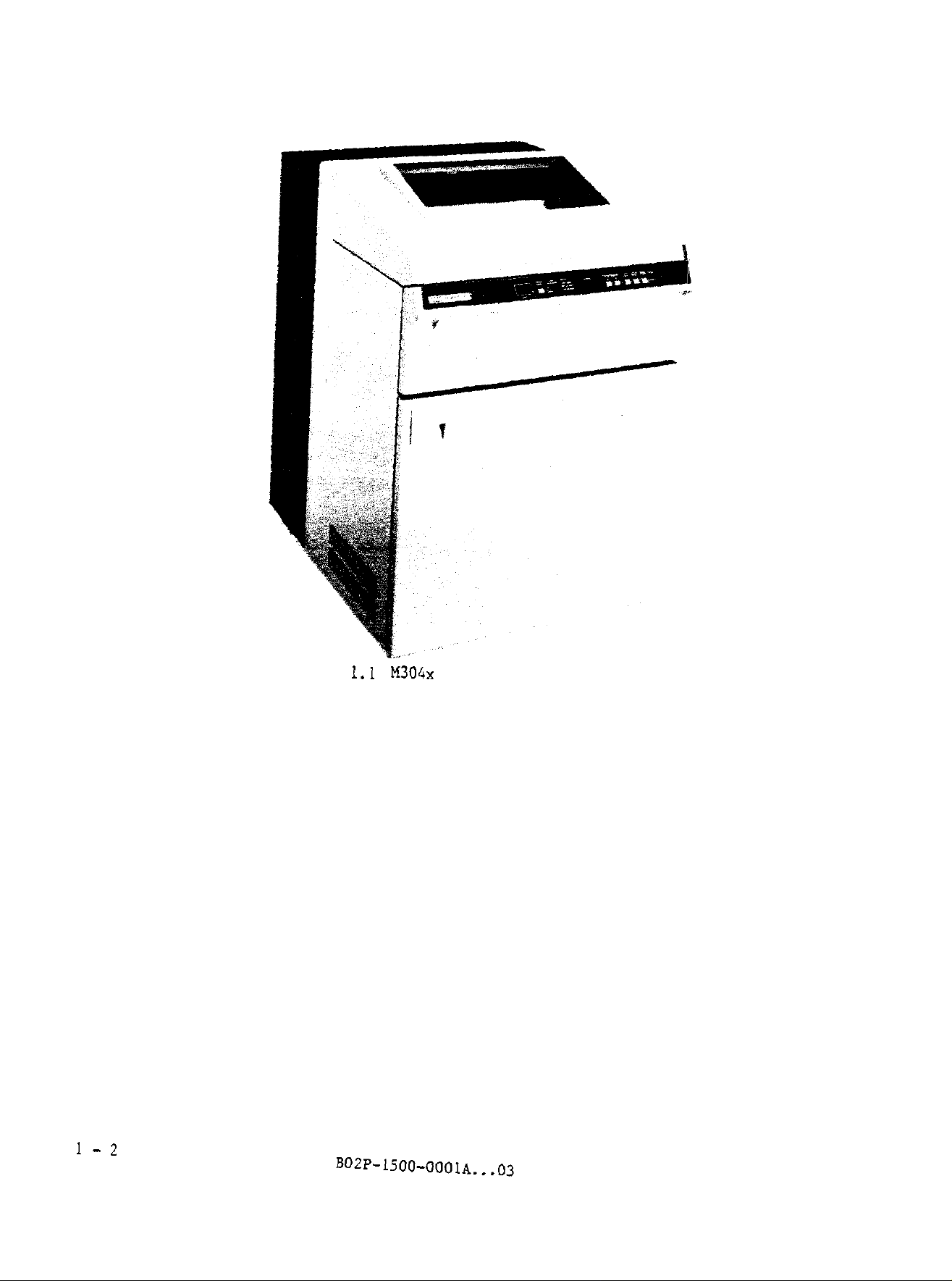
Figure
1.1 M304x
series line printer
1-2
Page 13
CHAPTER 2 SPECIFICATIONS
This section describes specifications of the M304x series
ribbons, and forms.
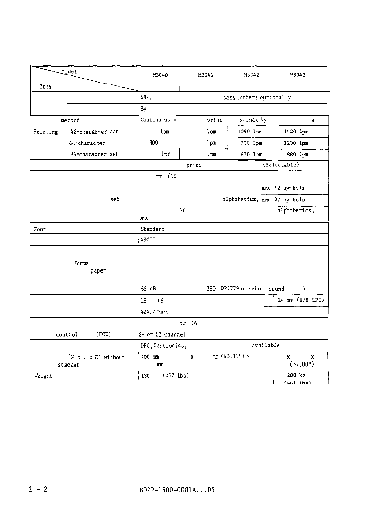
2.1 Printer Specifications
Table 2.1 lists the printer specifications. For electrical specifications and
ambient conditions, see Section 2.3.
DPC, Centronics or RS-232-C interface, see Chapter 4, 5, or 6.
For standard interface specifications,
:Line
printers,
B02P-1500-OOOlA...03
2-l
Page 14
Item
Print band ~ Type
'
Replacement
Table 2.1 Printer specifications
i48-,
64-, and 96-character
my
operator
sets (ochers optionally
available)
Printing mechod
Prinringj 48-character set
speed
~ 64-character
(
96-character set
set
Print positions
Character spacing
~Continuously
390
~
3@0
210
80, 132 or 136
2.54
nrm (10
rotating
Ipm
/
lpm ~
lpm
print positions per inch)
print
band
750
lpm
600
lpm
420
lpm
prinr
positions per line
~
str~xk b:;
rotary hammers
(:Selecrable)
Character ~ 48-character set 10 numerics, 26 upper-case alphabecics,
set
I
Font
type
Character code
Number of I Carbonless copy
copies
j
64-character
(
96-character set
I
set
;
10 numeric*,
26 upper-case
alphabecics,
10 numerics,26 upper-case and 26 lower-case
iand
32 symbols
~Scandard Gothic (others optionally available)
iASCI1 (others optionally available)
paper
~
6 (Including original)
j
Ferns with interleaved! 5 (Including original)
~
carbon
?aper
and
alphabetics,
~ carbonbacked forms
S5 dB
Sound pressure level
A (Conforms to
ISO. UP7779 srandarcl
so"nd level)
Forms feed I Line spacing time
rate
Vertical line spacing
Format
:
Continuous feed i424.2 mm/s
control
tape
(FCT)
option ~ 8- or
Interface
1
Dimensions
powered
11; x ii x D) without 1700 m
stacker
,18
i4.23 or 3.18 m (6 or 8 lines/inch)
:DPC, Centronics,
i
900
1 Weighr I180
ms (6 LPI)
(16.7 inches/s)
12-channel
FCT is available.
RS-232-C, and other
(27.56") x 1095 mm
fmn
05.43")
kg
(I?7 lbs)
(43.11") x
avai.lable
options
700 x 1095
~
960
(37.80")
I
x
I
2-2
BOZP-1500-OOOlA...05
Page 15
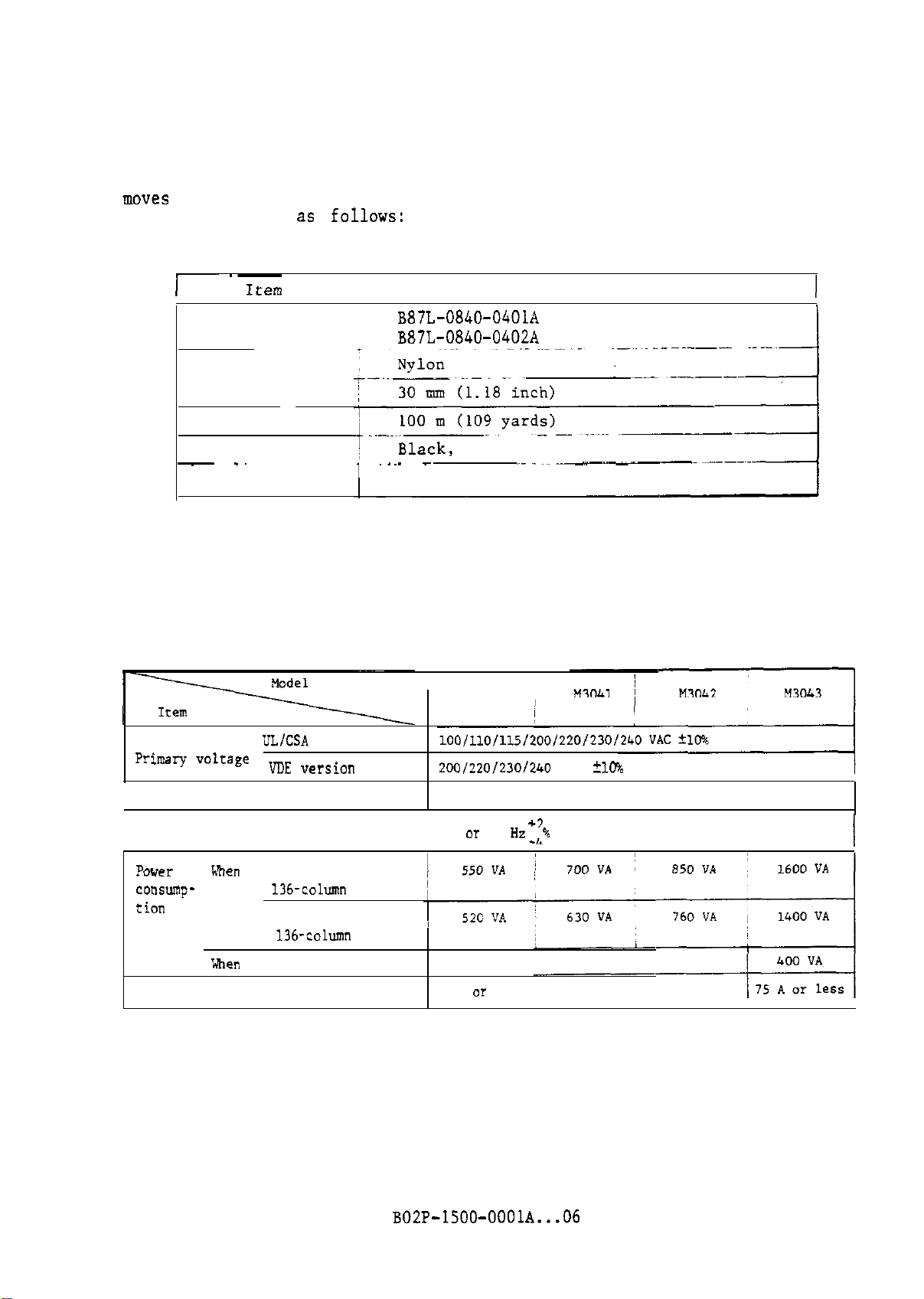
2.2 Ribbon Specifications
This printer uses an endless cartridge type or open-type ribbon, which only
moves
in one direction.
specifications are as
The ribbon is replaced by the operator. The ribbon
f0110ws:
Table 2.2 Ribbon specifications
I~ ~~
Item
Parts number ~
I
B87L-0840-0401A
Specification
(black)
B87L-0840-0402A (blue black)
Fabric
Width
Length
Ink
-
.~
Storage life
I ~-~- -
2 years
blue black
_..__~_
2.3 Installation Conditions
This section shows the outer dimensions,
electrical specifications,
and environmental conditions of the printer.
operation and maintenance area,
Table 2.3 Electrical specifications
I
M3040 j
I
Primary voltage
Phase
Frequency
POW7
consumption
Starting Surge
men
print- !
ing
When not printing
UL/CSA
version
I VDE
version
I
! LB-character set
136-column
64-character
~
136-column
printing
printing
200/220/2301240
Single phase
50 or 60 Hz
250 VA
50
A or less
+2
4%
VAC
20%
I
B02P-1500-OOOlA...06
2
-3
Page 16
x3040
xi3041
M304?
900
(35.43")
-9
M3043
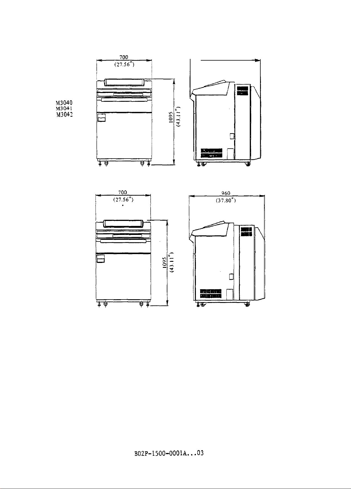
Figure 2.1 Outer dimensions (with the forms rack)
2-4
B02P-1500-OOOlA...O3
Page 17
i-
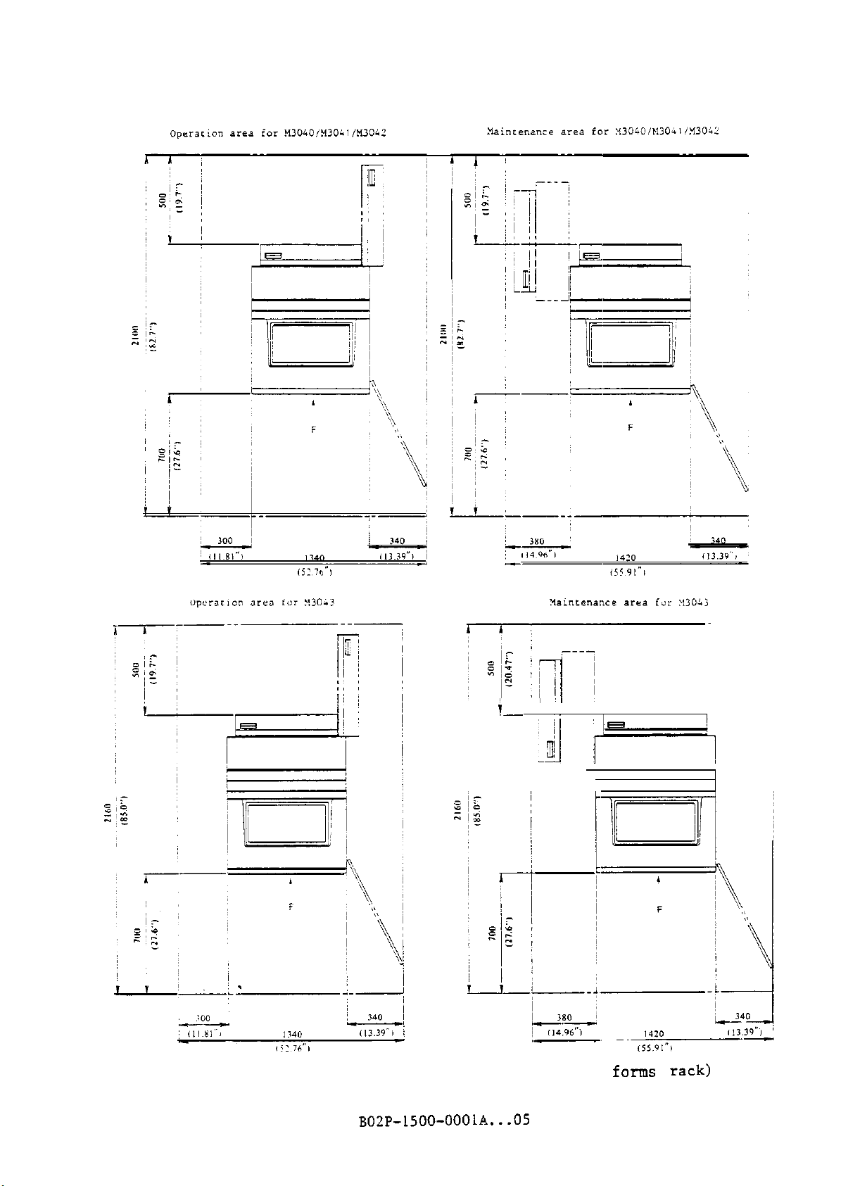
Figure 2.2 Operation and maintenance area (with the
B02P-1500-OOOlA...O5
forms rack)
2-5
Page 18
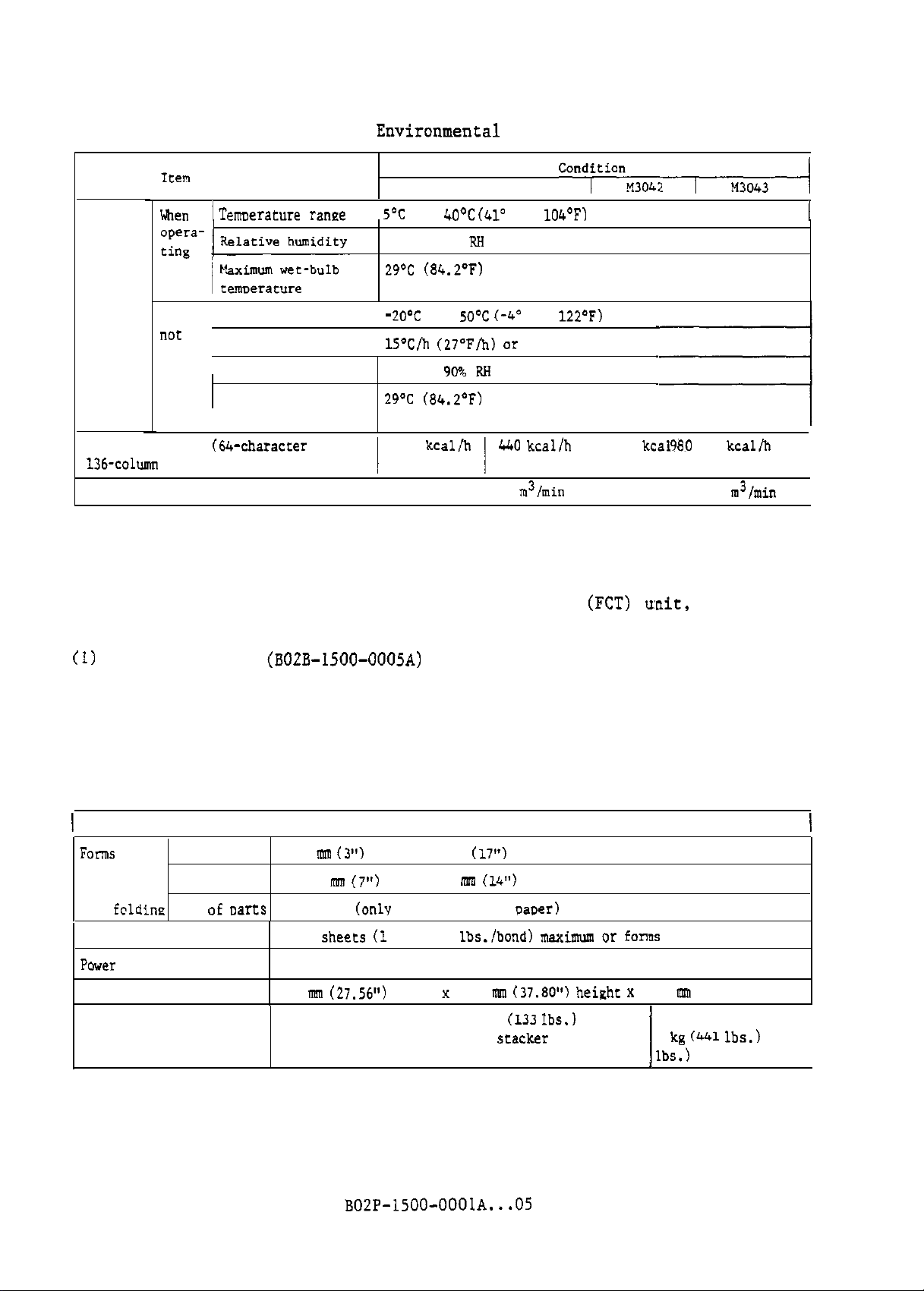
Table 2.4
Environmenral
conditions
Ambient
condi-
tions
When I
when
“CX
ope-
Temoerature
~ Temperature range / -
( Temperature gradient ! lS’C/h (27”F/h) or below
ranee 1
rating Relative 10% to
Maximum wet-bulb ZY’C
I temperature
Heat dissipation (6Lvcharacter set
136-column
printing)
Air flow
M3040
5’C
to 40aC
20% to 80%
290~
(84.20~)
20-Z
to
(84.2’F)
360 kcallh
I
I M3041
(41’
P.8
5O’C C-4’
90% RH
to 104’F)
(Without condensation)
440
5
condftianM304:T-rTA
to 122’F)
kcalfh 1 530 kcailh
I I
m31min
y80
kcal/h I
7
m3/min
I
I
2.4 Optional Unit
This section gives specifications of printer optional units such as the powered
stacker, long-line interface unit, format control tape
(FCT) wit,
line counter,
and paper puller.
(1)
Powered stacker
(BOZB-ISOO-0005A)
The powered stacker enables folding and stacking of forms.
lists the powered stacker specifications. Figure 2.3 and 2.4 show the
outer dimensions,
and the operation and maintenance areas for printers
with the powered stacker attached.
Table 2.5 Powered stacker specifications
I
Forms
available
for
fcldine
Capacity 3000 sheete (1 part, 17
Power
consumption
Dimensions
Weight
Item
I
’ Width 76.2 mm
Length
No. oE carts
177.8
1 to 5. 6 (only for carbonless paoer)
60 VA maximum (powered stacker only)
700
mm
Powered stacker only: 60 kg
M3040 to M3042 with powered stacker attached:
M3043 with powered stacker attached: 220 kg (485
(3”)
to 431.8 mm
mm
(7”)
(27.56”)
co 355.6 m
width
Table 2.5
Specifications
(17”)
(14l’)
lbs./bond) maxirmvn
x
960 mm (37.80”) height x 417 mm (16.42”) width
(133 Ibs.)
or fonos stacked 32 cm high
200 kg
1
(441 lbs.)
lbs.)
I
2-6
B02P-1500-OOOlA...O5
Page 19
M3040
M3041
M3042
700
(27.56")
1
M3041
M3042
'990
r
(,T
1050
r-14134.)
M3043
M3043
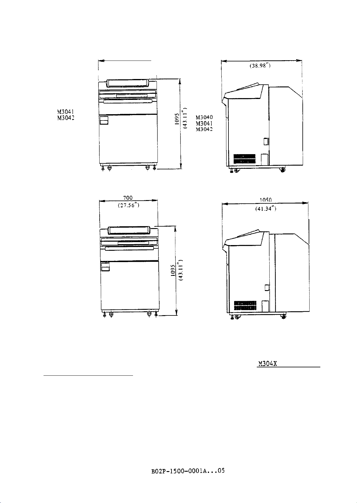
Figure 2.3 Outer dimensions (with the powered stacker)
The powered stacker can be operated using switches on the switch panel at the
top of the stacker.
Printer Operator's Guide.
For switch panel operation.
refer to M304X Series Line
BOZP-1500-OOOlA...O5
2-7
Page 20
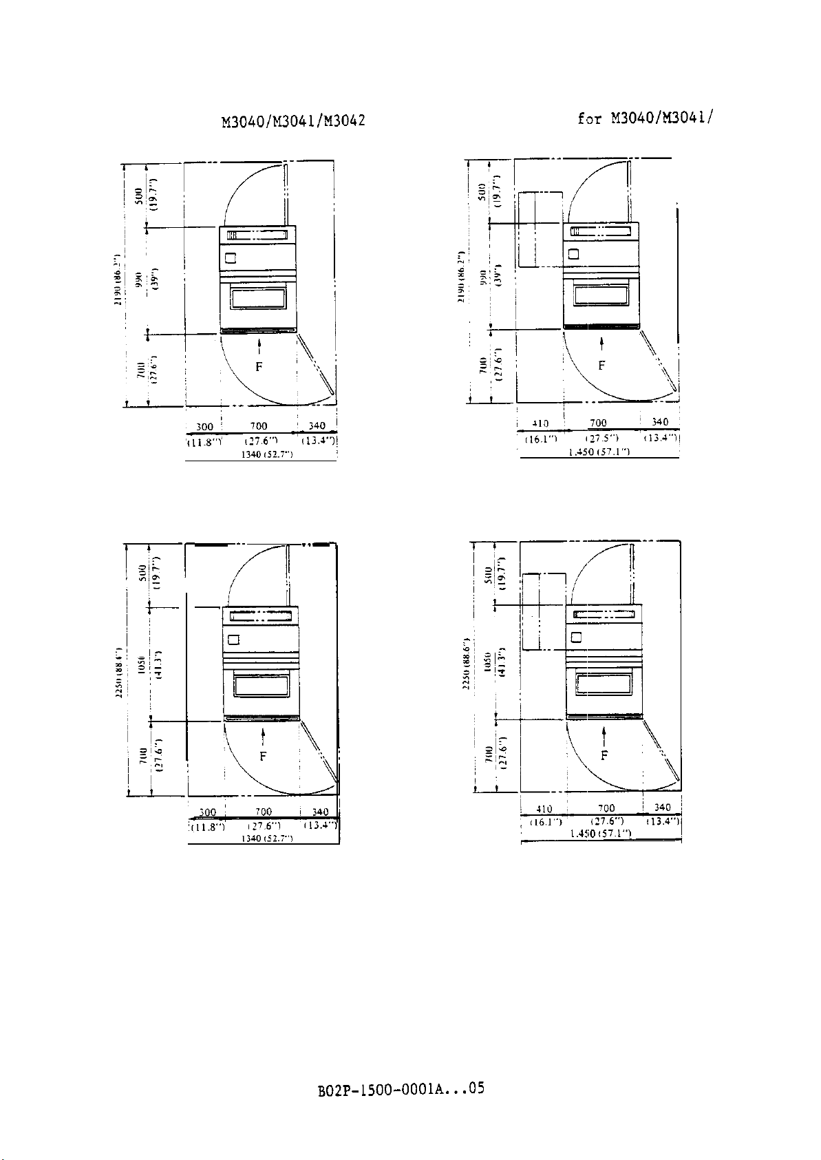
Operation area for M3040/M3041/M3042
with powered stacker attached
Maintenance area
M3042 with powered stacker attached
f'or
M3040/M3041/
1
Operation area for M3043 with
powered stacker attached
-_.
-r
T’
-
[5::3
el
Figure 2.4 Operation and maintenance areas
Maintenance area for M3043 with
powered stacker attached
..-
(with the powered stacker)
2-8 B02P-1500-OOOlA...05
Page 21
(2) Long-line interface unit
The long-line interface unit can transmit and receive differential-mode
interface signals via signal lines which can be up to 150 m in length.
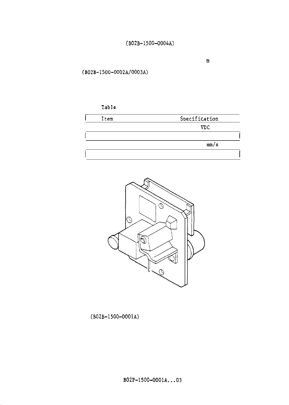
(B02B-1500-0004A)
(3) FCT units
The FCT unit reads format control data from the FCT and sends the data to the
printer.
FCT unit.
Table 2.6 lists the FCT unit specifications.
(BO2B-1500-0002A/OOO3A)
Tabl~e
2.6 FCT unit specifications
1~
I
Current
(
Dimensions
Item
Rated voltage
Tape speed
I
/
I
I
I
Figure 2.5 shows the
Soecification
6 to 12
0.4 A maximum
75 to 200 mm/s
To be supplied
VClC
I
I
I
I
I
Figure 2.5 FCT unit
Line counter
(4)
The line counter counts up by one every time 100 lines are printed.
(B02B-1500-OOOlA)
B02P-1500-OOOlA...03
2-9
Page 22
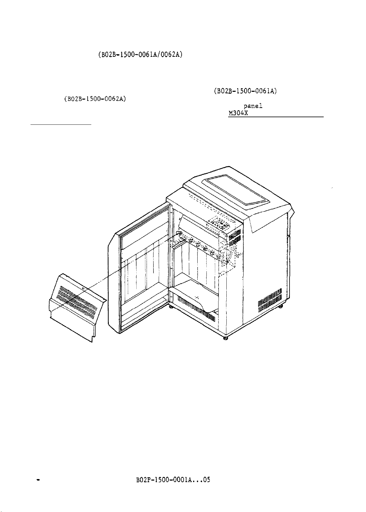
(5) 'Paper puller
(B02B-1500-0061A/0062A)
The paper puller,
forms folding.
The paper puller is supplied only as a parts kit (B02B-1500-0061A) or as an
assembly
the same way as the power stacker, that is, by using the
upper part of the forms rack.
Operator's Guide.
Figure 2.6 shows the paper puller.
(B02B-1500-0062A)
installed in the forms rack, pulls printed forms to improve
with a forms rack.
For details,
The paper puller is operated in
par~e!~
installed at the
refer to M304X Series Line Printer
2 - 10
Figure 2.6 Paper puller
B02P-1500-OOOlA...05
Page 23
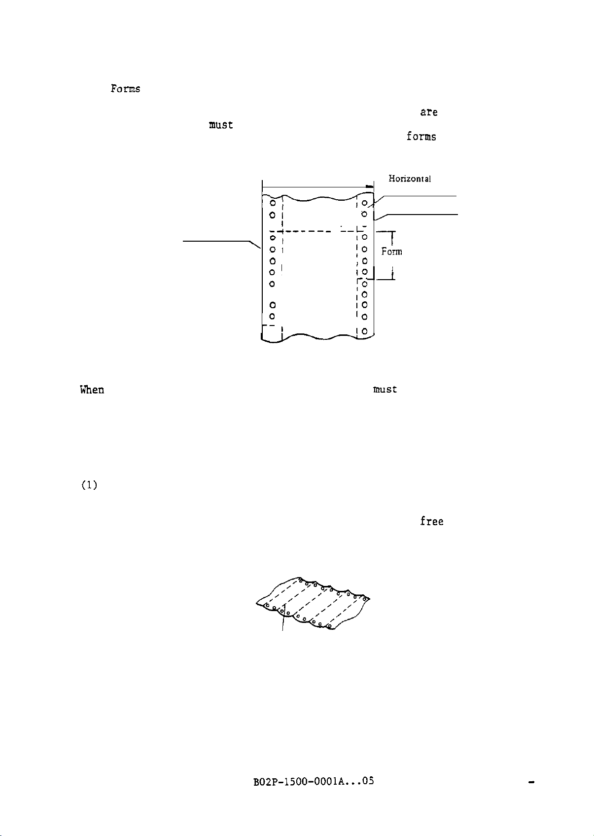
2.5
Form
Specification
Continuous
printers.
fanfold forms,
The forms
single copy or multiple copy,
must
have pin feed holes evenly lined up on both sides and
horizontal perforations that run perpendicular to the
See Figure
2.7.
Vertical
perforations
'
Forms width
--+---CA
01
01
0
1
o+-----
--ko
01
0
0’
--A---------
fJ
I
0 I
0 1 10
I
-0
I
----------A--
0 1
HoIiZOIXil
-
perforations
0,
I
Pin feed hole
7
FOrIll
lo
length
10
‘O--i
:O
10
‘0
10
Figure 2.7 Forms
When selecting forms for this printer,
the user
must
conform to the following
forms specifications:
are
used for the
forms
feed direction.
2.5.1 General note about forms
This
section describes paper quality and shape of the forms container.
Paper quality
(1)
paper used for forms should be of good quality, opaque, not too elastic,
and suitable for printing. The paper must also be
wrinkles,
and tears.
Torn paper can cause printing trouble.
Curled forms es shown in Figure 2.8 will not be fed or stacked correctly
after printing. Do not use curled forms.
*
Figure 2.8 Curled forms
Perforations
:free
from dirt,
B02P-1500-OOOlA...Of
2
- 11
Page 24
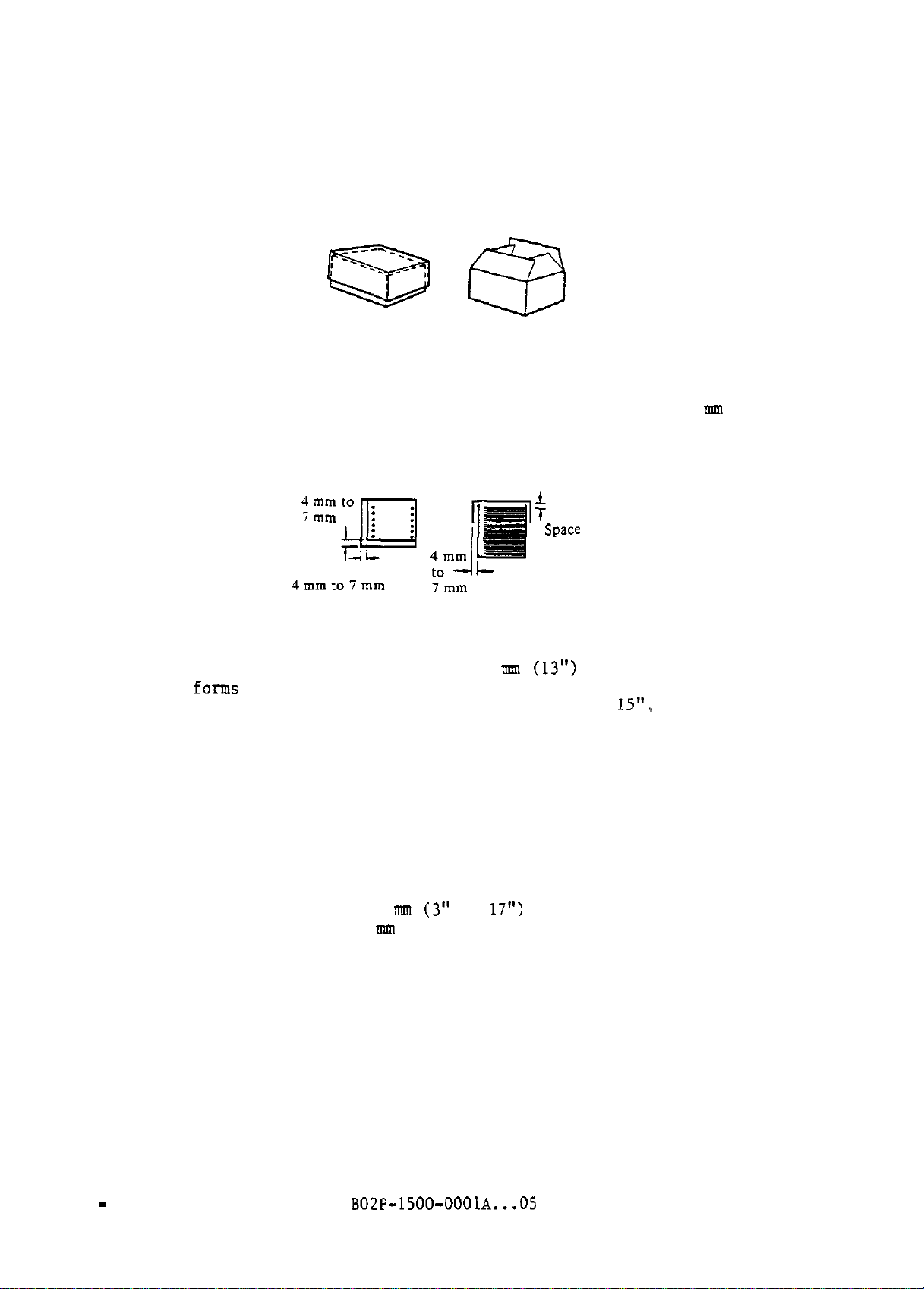
(2) Forms container
If the forms catch on container lids when being fed, feed errors may
occur.
Therefore arrange the lids as shown in Figure 2.9.
Allowable
Figure 2.9 Forms container lids
Inside space between the forms and container should be 4 to 7 mm (0.16" to
0.28").
The bottom of the box must be flat.
(Top view) (Side view)
Unallowable
See Figure 2.10.
f
space
Figure 2.10 Shape of the forms container
The forms container height must be 330.2
in the
If the form length or folding dimension is more than
rear doors must be open during operation.
forms
hopper.
rmn (13")
or less to be installed
IS":,
the front and
2.5.2 Dimensions
This section describes dimensions of the forms, printing area, pin feed holes.
and perforations.
(1) Forms dimensions
Forms width:
Forms length:
2 - 12
76.2 to 431.8 mm
76.2 to 381 m (3" to 15")
B02P-1500-OOOlA...OS
(3"
to
17")
Page 25
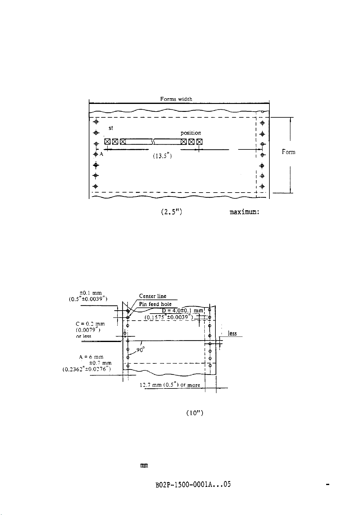
(2) Positions and dimensions of the printing area
Figure 2.11 illustrates the distances between the leftmost and rightmost
print-position centers of the printing area and the pin feed hole center.
+
I st print
+
position
km--wlxlm
-t
-
$A
-+
A- maximum: 63.5 mm
Figure 2.11 Leftmost and rightmost print positions
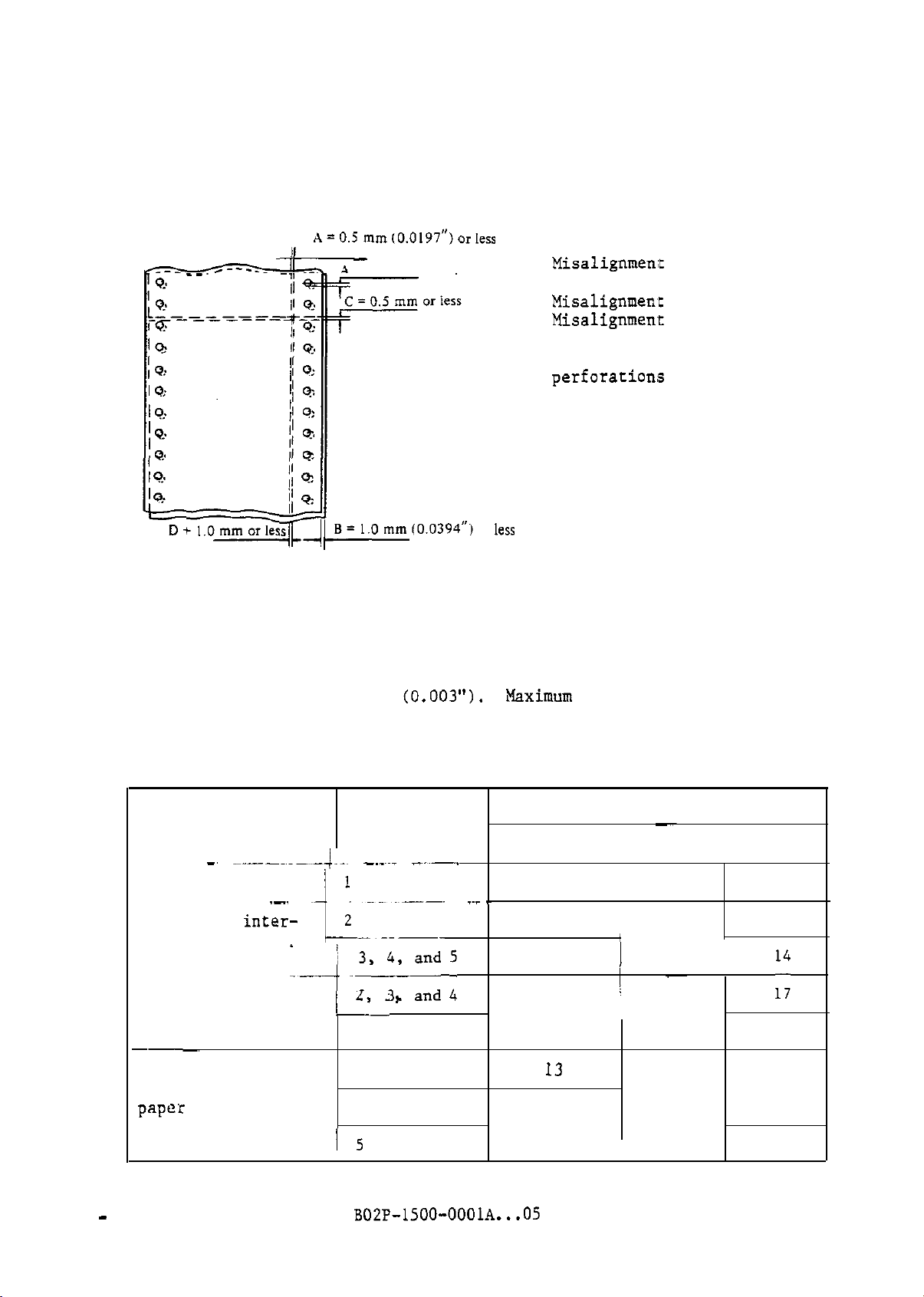
(3) Pin feed holes
Pin feed holes must be round.
are given in Figure 2.12.
B = 12.7 mm
342.9 mm
(13.5")
136th print
posiiion
-
(2.5")
The dimensions relating to pin feed holes
B
I +
B-
maximun:
E = 0.2 mm
or
less
FOTC
length
--I
68.6 mm (2.7")
A: Distance between
the forms edge and
pin feed holes.
B: Distance between
two consecutive pin
feed holes.
C
: Misalignment of the
pin-feed hole
center with other
holes.
D: Diameter of a pin
feed hole.
E: Misalignment of the
pin feed hole with
a hole on the
opposite side.
Note:
Poorly shapted pin feed holes and misalignment between left and right pin
feed holes may result in inferior paper tensile strength. Misalignment
must be within 0.2 mm (0.0079").
The total misalignment of any two holes on opposite sides of
forms along a 254 mm
(0.0118").
Figure 2.12 Dimensions relating to pin feed holes
B02P-1500-OOOlA...O5
(10")
length must not exceed 0.3 mm
2 - 13
Page 26
Pin feed holes that touch horizontal perforations may damage the paper.
Pin feed holes must not overlap horizontal perforations.
Hanging hole
stick to the printing area,
chad
will likely cause problems with the printer.
resulting in printing cutoff characters. Do
Chad may
not use such forms.
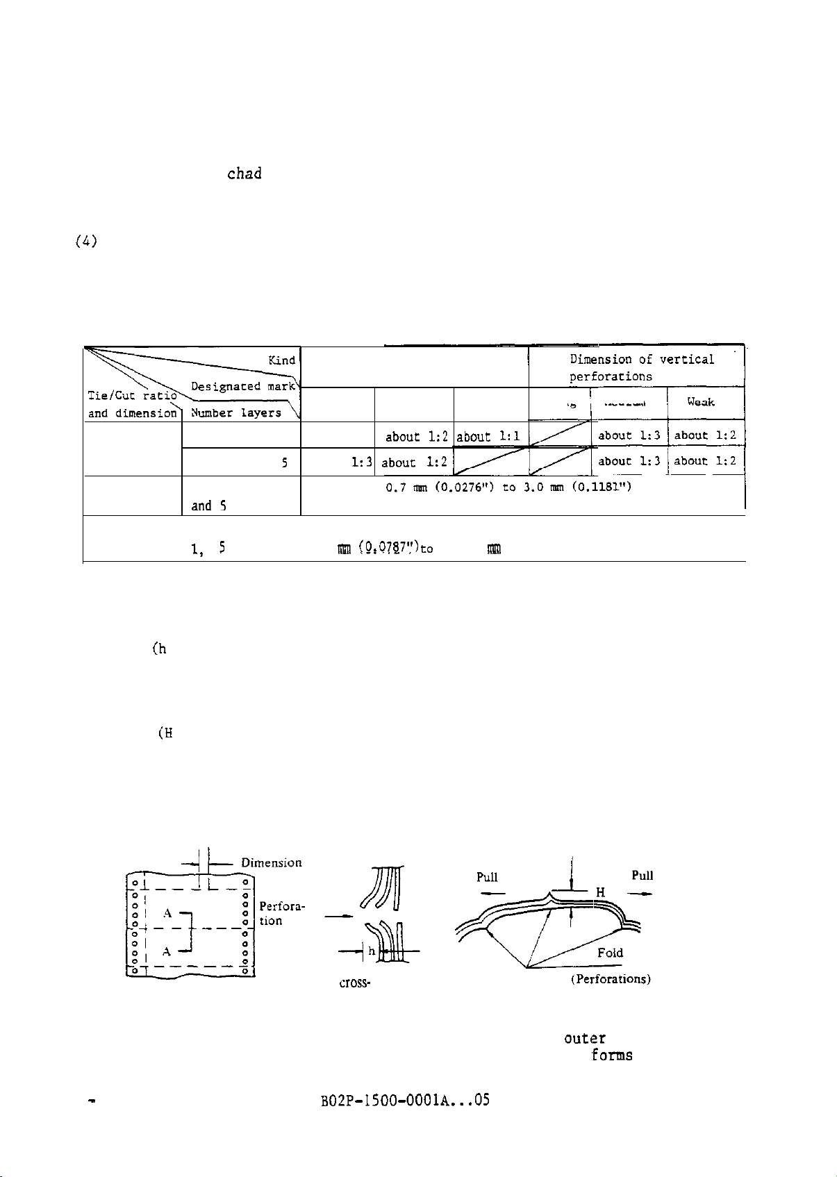
(4)
Perforations
Perforations must be straight. The perforations should be of the size
shown in Table 2.7.
Table 2.7 Perforation dimensions
Dimension of horizontal
perforations
Tie/Cut ratio 1
2,
3, 4, and
Tie dimension 1, 2, 3, 4,
and 5
and
Cur
dimension
1,
2, 3, 4,
5
about 1:3
5
2.0 ml (0.0787")
1.2 mm (0.472")
strong
Medium Weak
abollr 1:2 about 1:l
about 1:2
3.0
to 1.2m(0.0472")
rmn
Strong 1 Medium
/
(0.1181")
co
I
Use weak or medium perforations shown in Table 2.7. The dimensions of
horizontal perforation should be 2 mm (0.0787") or less.
If the
dimensions of horizontal perforations exceed 2 mm, the portion sticking
out (h in Figure 2.13) at the cutting edge becomes large! and feed error or
forms damage may occur.
If separation at the perforations (fold) between each part is too great,
the forms may be damaged or ink stain may result.
The raised part at the
fold (H in Figure 2.13) must be 2 mm or less with the bottom layer kept
flat by force.
Figure 2.13 shows the protrusion and separation of the outer layer at the
perforation of multiple-part forms.
Expended
CIOSS-
sectional view of
A-A'
Figure 2.13 Protrusion and separation of the
at the perforation of multiple-part
2 - 14 B02P-1500-OOOlA...O5
outlzr
layer
~forms
Page 27
2.5.3 Multiple-part forms
This printer utilizes up to 6-part forms. Interleaved carbon paper utilizes
6-part forms and is not included in the number of parts. Forms with
interleaved carbon paper, carbon-backed forms, and forms using carbonless copy
paper are available as multiple-part forms.
must meet the specifications in Subsections 2.5.1 and
the same length and width.
This section describes the fastening, misalignment, and thickness of
multiple-part forms and also how multiple-part forms cause feed defects.
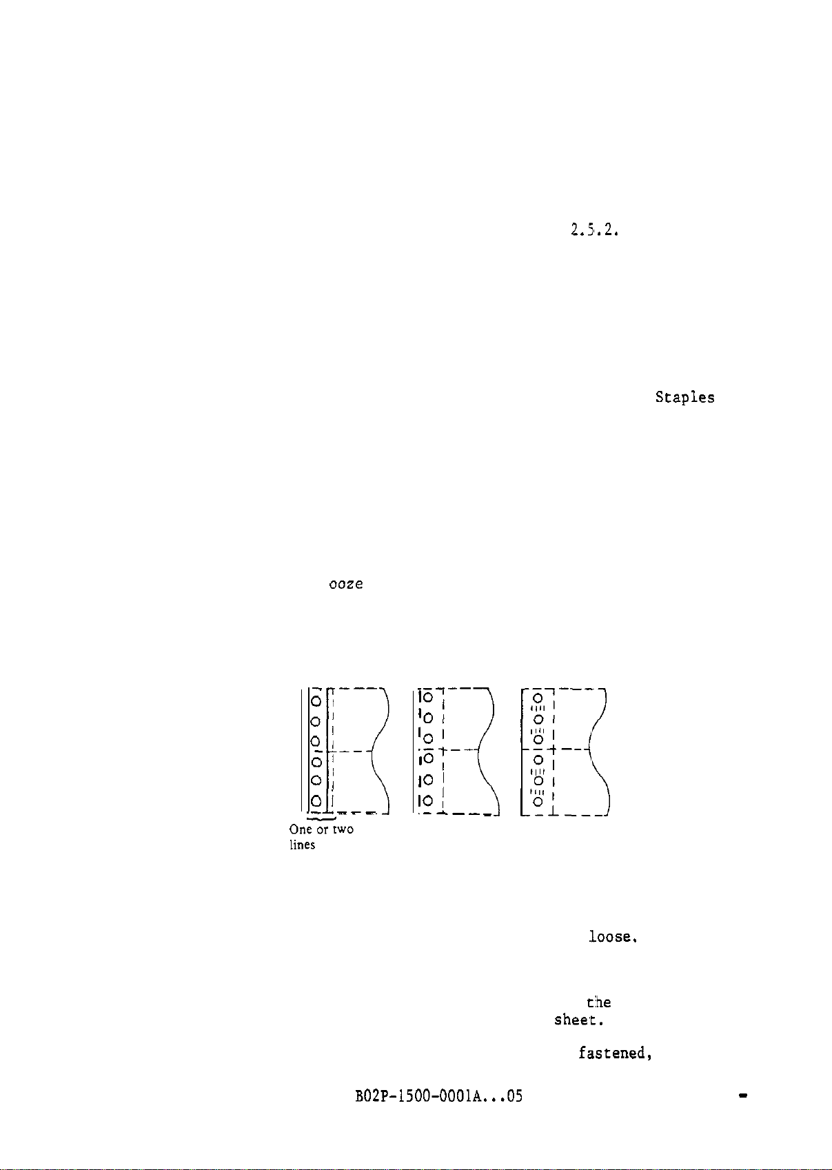
(1) Fastening multiple-parts
Each part of multiple-part forms must be fastened together at one or both
pin feed hole areas by gluing or crimping.
interleaved carbon paper should be fastened on the right.
not be used on forms.
damaged and a feed error will occur.
For gluing, do the following:
. The shape of glued parts should be dots or stripes in the vertical
direction, as shown in Figure 2.14,
. Glue should be applied evenly and must not cause wrinkles or discolor
the paper.
. Do not apply glue to the perforations. If stripe gluing is necessary,
the glue must not
layers.
. Glue cannot be used if forms lose pliability.
If they are used,
ooze
through perforations of the top and bottom
Each part of multiple-part forms
2.5'.2.
Multiple-part forms with
the printer print section will be
They must be of
Staples
must
Stripe
gluing
-
---
0
I
Dotted
gluing
iO7--
Crimps
‘0 I
O/
0
I
0
I--
0 !
0 I
---
It
-5
Figure 2.14 Methods of fastening paper
For crimping, do the following:
. Layers must be firmly fastened and must not come
. There should be no paper tailings or dust.
. Forms should maintain their shape so as not to cause jams.
. Crimps must not overlap horizontal perforations.
horizontal perforations,
. Crimps should not project through the bottom
If layers of multiple-part forms are not properly
likely to peel apart, causing feed defects.
‘0 ’
;Et--
IO
1
10
,
._A___
I<
the forms will tear at
shee,t.
:Loose.
If crimps overlap
t:he
perforation.
f,astened,
the layers are
B02P-1500-OOOlA...05 2 - 15
Page 28
(2) Misalignment of paper
Misalignment between layers should be within the range shown in Figure
2.15.
Misalignmen;t
= 0.5 mm or less
or
Figure 2.15 Allowable incorrect alignment of multiple-part forms
(3) Thickness of parts
Thickness of parts should be uniform.
area must be within 0.076 mm
(including edges) is 0.6 mm (0.0236"). Table 2.8 indicates recommended
bond weight of each layer according to forms type.
(0.003").
A:
holes
B:
Misalignmen,t
c:
MLsa1ignmen.t
perforations
D:
Misalignment of vertical
perforatiom
less
Thickness deviation in the print
Maximum total thickness of forms
of pin feed
of edges
of horizontal
2 - 16
Table 2.8 Recommended bond weight of forms
Forms type
-~ ----...-~~-i.-
Single-part forms
Forms with
leaved carbon paper
Carbon-backed forms
-~
Forms using
carbonless copy
paper
inter-
--. l-r--.
.~-j -=I;;
iL
I5
No. of parts
_..~~. -~.~-.
1
2
1
'
5
2 and 3
4
B02P-1500-OOOlA...O5
Recommended j Minimum I Maximum
-~--
Bond weight (pound/bond)
17 ~
14 I
12.5
11
13
11
-
4
125 /
)
I 11
15
-
:
11
/
28
17
:;
11
17
11
Page 29
When
multiple-part forms are used,
parts (layers), HOWeVer,
the weight of each part should be that given in
the forms can have different weights of
Table 2.8 according to the number of parts.
When forms ar too thick, density fading between the top and bottom of each
character will occur.
When forms are too thin, they will be damaged and a
feed defect will occur.
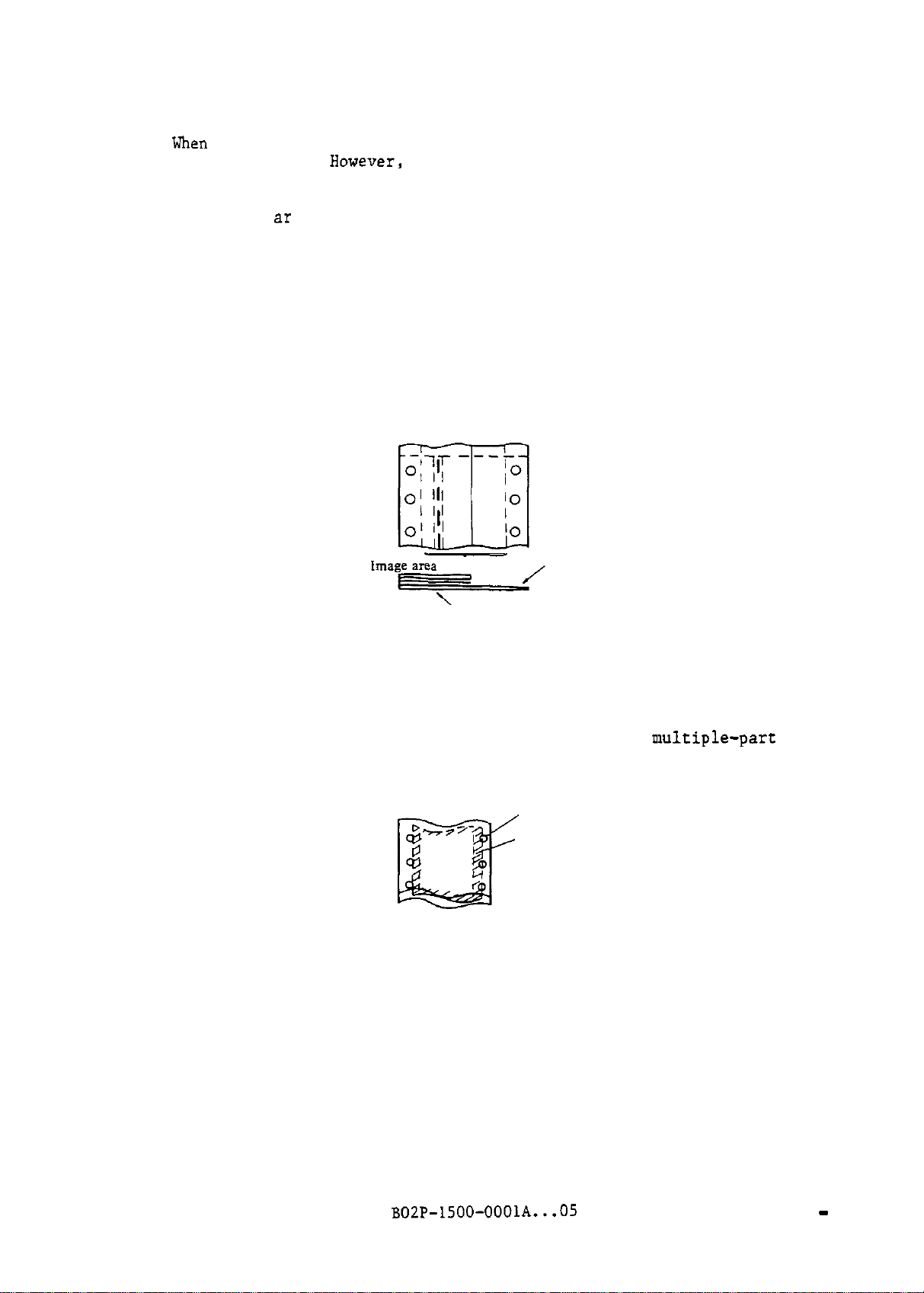
(4) Forms causing feed defects
The following forms are likely to cause feed defects, excluding those
described before:
. Multiple-part forms with layers whose thickness or number varies by
section, such as shown in Figure 2.16.
Glued
portions
'Glued portions
Figure 2.16 Multi-part forms with layers of different thickness
. Multiple-part forms with layers glued in the print: area (Printing should
not be done on the glued portions.)
. Carbon paper which is covering pin feed holes of uultiple-part forms
(see Figure 2.17.)
Pin feed hole
Carbon paper
Figure 2.17
Carbon paper covering pin feed holes
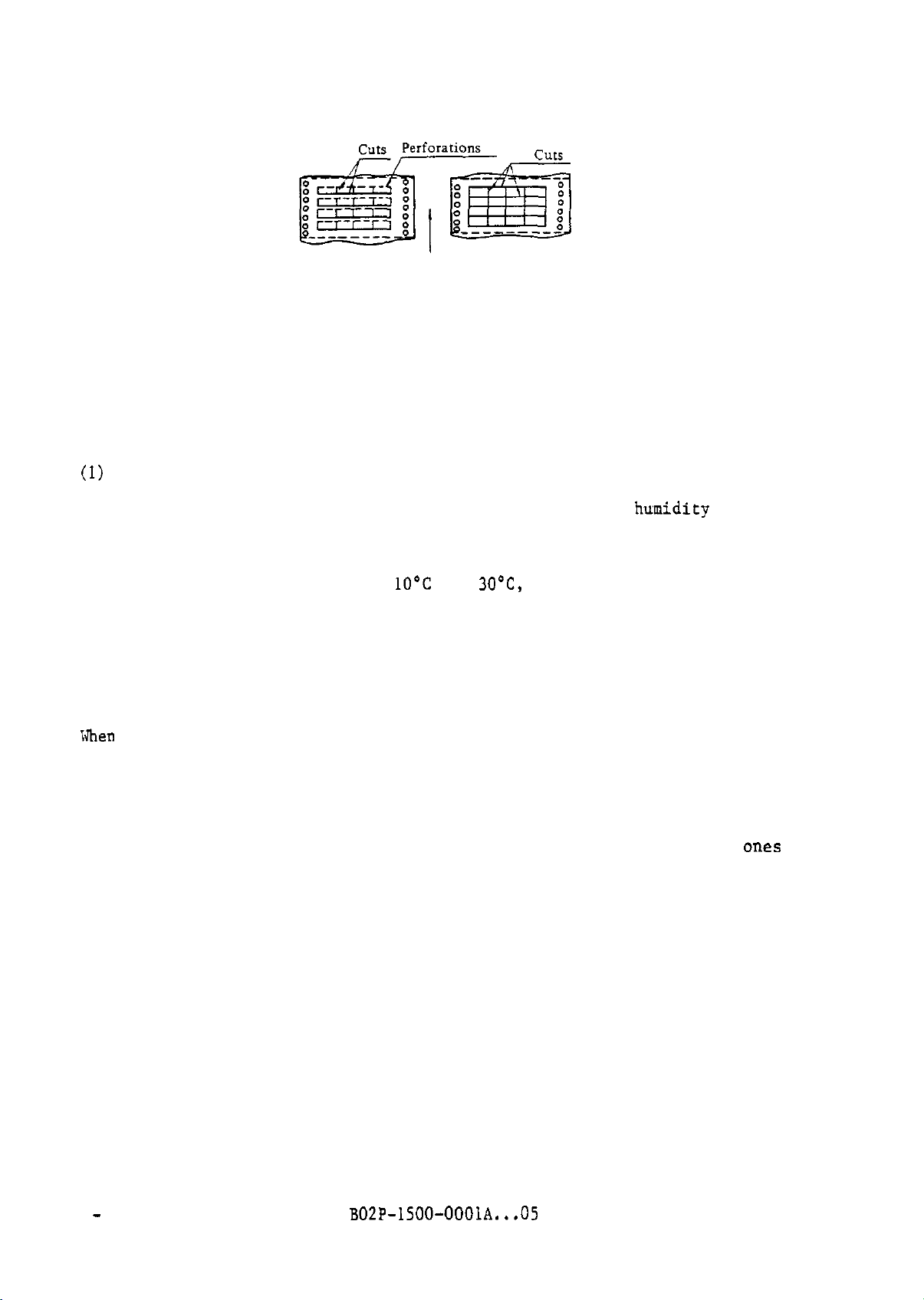
. Self-adhesive label form with labels whose all sides are cut (see
Figure 2.18)
Such forms are likely to peel off.
The forms feed 'direction side of every
label must be perforations to prevent peeling.
BOZP-1500-OOOlA...O5
2 - 17
Page 30
Forms
feed direction
allowable Unallowable
Figure 2.18 Self-adhesive label forms
2.5.4 Ambient conditions for forms
The following are the ambient conditions in storage and usage:
(1)
Storage
Temperature should be with 10°C to 30°C and,
(2) Usage
Temperature should be within
70%.
If the conditions where it is stored and used are different, keep
1O'C
to
30°C,
and relative humidity 30% to
the paper for more than 48 hours in the environment where it will be used
before using. it.
2.5.5 Purchase order for forms
ordering forms, specify the following items:
m-K?*
Forms dimensions
The number of parts
Bond weight of each part
Perforation position
Perforation dimensions (tie and cut) for horizontal and vertical
Carbon paper position (If carbon paper is used)
Carbon-backed position (If carbon-backed paper is used)
Fastening method for multiple-part forms
Color of each part
Type of carbon paper (If carbon paper is used)
Carbon color (If carbon paper or carbon-backed paper is used)
Copy color (If carbonless copy paper is used)
Preprint on forms
relative humidity 30% to 70%.
ones
For more detailed specifications, specify as required.
forms, prepare a sample in advance and test it.
Order after confirming that it
When specifying special
will work.
2 - 18
B02P-1500-OOOlA...O5
Page 31

2.6 Format Control Tape
(FCT)
The 8- and 12-channel format control tapes
format
the FCT unit.
2.6.1 Medium quality
Medium used for the FCT should be:
Total thickness:
Light transmittance: 5% or less
The FCT made up of a polyester resin film and paper would be stronger at
tensile, tearing, and folding.
2.6.2
The FCT dimensions vary with the 8- and
as shown in Figure 2.18.
control data into the forms control buffer
FCTs
must conform to the following FCT specifications:
0.100 to 0.110 mm (0.0039" to 0.0043")
Dimensions
(FCT)
are used for loading vertical
(FCB) o:E
i2-channel FCTs.
the printer using
The dimension must be
B02P-1500-OOOlA...05 2 - 19
Page 32

9.96 + 0.05
Refe
-
,3.40
k 0.04
(1.000”‘0.002~)
4~.~04fO,ljO (1.6:22”?0.005”i
.A\:
Total tolerance
0.005 inches
0.013 inches for
for lOsprocket-hole
pitches
pitches
,&channelFCT)
50
sprocket-hole
30.602tO.
-e
-&
+
I i (0.8 I l”f0.004”)
(Channel-l side)
-‘-
-0.03
,n
Inl”+o
-. . - -
,
itI--
(0.0697”‘0.0020*)
-0.001")
.77*0.05
---.
1) The Y-Y' line is a sprocket-hole
center line perpendicular to the
reference line.
2) When diameters of damaged sprocket
holes become 0.005 inches wider
than normal, replace the FCT.
Figure 2.18 Specifications of
2- 20
B02P-15@0-OOOlA...05
Y‘
(I?-channel FCT)
c:
Reference line
FCT
Page 33

CHAPTER 3 CONFIGURATION
The printer consists of the mechanical unit, control unit, forms rack, rear
door and cabinet.
The operator panel,
control unit.
The top cover and front door are included in the cabinet.
control circuit board, and power supply are included in the
Figure 3.1 shows their locations.
Rear door
Powersuppiy
Operator
/
pane1
\ Front
door
Figure 3.1 Printer configuration
BOZP-1500-OOOlA...03
3-l
Page 34

3.1 Mechanical Unit
The mechanical unit consists of the following:
. Base unit (includes the print-band drive section)
. Print unit
. Forms feed unit
. Ribbon unit
(1)
Base unit
The base unit is fixed to the cabinet frame.
motor, a pair of band pulleys,
and a variable-reluctance transducer for
A platen,
a print-band drive
detecting each type location are in the base unit.
The print-band drive section has a simplified structure for easy
print-band replacement by the operator.
(2) Print unit
The print unit is attached to the base unit and consists of four
haPmner
magnet assemblies and a print unit frame.
The print unit can slide horizontally to the base unit by using a lever on
the base unit to make the forms path wider so that an operator can easily
load
forms.
The hammer magnet assemblies consist of magnet assemblies and hammer
assemblies, with hammers for 136 print positions.
quality, rotary-type hammers are employed.
Hammer magnet coils are
To improve print
arranged with sufficient space around them to ensure hammer-unit
compactness.
(3)' Forms feed unit
The
forus
feed unit is fixed to the print unit frame.
A pair of forms
tractors with a lever for adjusting their horizontal position, forms
tractor drive mechanism,
forms feed unit.
The ADVANCE FORMS knob for adjusting the vertical forms
and a stepper motor to drive the unit are in the
position, and the SHIFT FORMS knob for adjusting horizontal forms position
are also provided.
(4) Ribbon unit
The ribbon unit is fixed to the base unit.
KOlbS?CS,
a ribbon
feed,motor,
a ribbon feed sensor,
It consists of ribbon feed
ribb#on
guides, and a
ribbon container.
3-2
B02P-1500-OOOlA...03
Page 35

3.2 Control Unit
The control unit consists of the following (see Figure 3.2):
. Control circuit
. operator panel
. Hammer magnet driver (with the register unit only for
. Power supply
Control circuit
(1)
The control circuit is on one PC board and is installed in the maintenance
which can be accessed by opening the forms rack at the rear of
(2)
section,
the printer.
The control circuit uses 2 microprocessors; one for interface control and
the other for printer control.
The LSI for print control reduces the number of parts and improves
reliability.
Operator panel
The operator panel is located at the upper front of the printer. Control
switches and indicator lamps on the operator panel
M3l343)
ar'e
on a PC board.
Hammer magnet driver
(3)
The hammer magnet driver for the 136 magnets is on one PC board. In
113040,
connected directly to the magnet assembly on the PC board. In M3043, the
hammer magnet driver is installed near the control circuit board and the
lead from the magnet assembly is connected to the hammer magnet driver
through the register unit.
A simple circuit is achieved by using custom
enabling easy detection of faulty columns.
Power supply
(4)
The power supply consists of the supply unit and a transformer.
The transformer is connected to an AC input through a line filter and a
circuit breaker.
switching the appropriate tap on the transformer.
The power supply unit has regulation circuits for logic circuits and
hammer magnet driving,
control relays
M3041, M3042, it is installed on the rear of the print unit and is
ICs
and a transistor array,
Input voltages of 100 to 240 V can be selected by
a forms feed stepper motor drive circuit, and
for the AC motor.
B02P-1500-OOOlA...03 3-3
Page 36

7
(only for
M3043)
Mainframe
.AC
input
Inpuf/outpuf
mterface
--/
L--------J
COllt~Ol
circuit
L
Power supply
Figure 3.2 Control unit
Hammer magnet
Mechanical unit
I
-
3-4
B02P-1500-OOOlA...O3
Page 37

CHAPTER 4 DPC-COMPATIBLE INTERFACE
This chapter describes the DPC-compatible interface used for the I/O interface
connected to the
M304x
series line printer (printer).
4.:
Basic printer operations, data transfer, printing, and forms feed are shown in
Figure 4.1.
I
Operation Outline
/
Dara
transfer cycle
Print
data
Control code or the Skip 01 Space command
with the
Data edition
Paperlnsrruction
signal
Data
rransfer
Print data
c:ycle
F
Print
cycle
Data Request=
I
j
1
Approx.14ms 1
Figure 4.1 Basic operations
The printer starts the print cycle after receiving l-line print data sent from
the mainframe and one of the following:
. Control code (LF, FF, or CR code)
. Skip command (with the Paper Instruction signal =
. Space command
For the control codes and the Paper Instruction signal, see Sections 4.3.2 and
4.4.2.
the control code or with the Paper Instruction signal.
Data Request signal to one 14 ms before terminating forms feed and starts
receiving the next line of data during forms feed.
After l-line printing,
(with
the Paper Instruction signal = 1)
the printer starts the forms feed specified by
B02P-1500-OOOlA...05
1)
The printer sets the
Therefore, unless the next
4-1
Page 38

line data is received within 14 ms,
the print speed of the printer drops and
does not achieve the rated print speed.
If the control code or the Paper Instruction signal is received without print
data,
the printer does not print and only feeds forms.
If the received print
data is more than 132 or 136 bytes (one of them is selectable), data of the
133rd,
than 132 (or
137th or higher byte is ignored. If the received print data is less
136)
bytes,
the remaining data is printed as spaces.
The print operation above is shown in Figure 4.2.
Control code or the Skip or Space command
with thePaper Instruction signal
Data edition
I
Data Request= 1
Print operation for
bytes' fo 136
Fuigure
4.2 Print operation
4.2 Interface Signals
This section explains the interface signal functions and physical
specifications.
4.2.1 Interface signal lines
Table 4.1 explains the OPC-compatible interface signal lines. Figures 4.3 a
4.4 show the timing chart of this interface and the timing specifications in
data transfer respectively.
This printer has a print data buffer
(PDB)
for 136 characters.
While a WMR
signal and Online signal are being generated, print data is received according
to the Figure 4.3. Printing starts after the following control code or Paper
Instruction signal is received.
4-2
BO2P-1500-OOOlA...O5
Page 39

Table 4.1 DPC-compatible interface signal lines (Positive logic)
Signal name
Signal
level
(+)
Direction
COiltfSlltS
kite Machine
Leady mire
Online
Data Request
CDTRQ,
Write Strobe
(WSB)
1 0
5v 0
1 j
'5V
5v 0
5v
0
0
System-Printer
1
This signal is high (logical 1) when the following
conditions are satisfied for
. Power has come on and all voltage levels are
nollna1.
i EE H~~"b,"~~:'i:'~~:",e,.,,ed.
Initlallzatxon process has been completed.
. The hammer drive system is normal.
. An error is nor dececced.
This signal enables information to be transmitted
with the system connected to the printer and goes
high when the following conditions are satisfied:
. Write machine
. The START/STOP switch is pressed.
. The print band is rotaxing normally.
A synchronizing signal for data transferred from
the system, and is high when daEa from the system
can be accepted.
This is a strobe signal for Write Information
the printer. The printer resets its Data Request
signal when the leading edge of this strobe signal
is received.
beady (FMR)
the
printer:
is 1.
to
Write
Information
(WIFl-8)
Buffer Clear
(BCLR)
connect 1
Connect 2 of the interface connector.
Paper
Instruction
l-8
(PI) /
5v
5v
- i-
5v
0
0
0
This is
7-bit codes, WIFE can be ignored by setting.)
The data for one line scored in the buffer of the
printer is cleared by this signal.
This signal is used for confirming the connection
connector is connected, the Connecr 1 and Connect 2
lines are connected.
'Ibis
by the sysrem. When this signal is logical 1, the
input data on the WIF lines is stored in the FCB.
This signal is checked 'by the printer at the timing
of the Write Strobe signal in the same way as WIFl
to
WIFE. For derails, see Section 4.4.2.
the
input data from the system. (For ASCII
When the interface
signal is high when forms control is performed
BOZP-1500-OOOlA...05 4-3
Page 40

Table 4.1 DPC-compatible interface signal lines (Positive logic) - continued
Signal name Direction
System-Printer
Write
Information
Parity
Write Check
(++)
paper
Cc-)
Bottom of Form / 5 V 0
(++)
Top fo Form
(++>
IDENT
IDEw 1
(WIFP)
Moving
0 (++)
l5V oi
5v 0
5v
0
COIltentS
Even parity signal for data from mainframe.
! parity is also available by setting. This signal
can be ignored by setting.
If a parity error occurs in
/
sysrem,
I
When rhe
signal is logical 1.
when
i
this signal is logical 1.
‘Ihis signal indicates the type of print band.
IDENT 1 IDENT 0
this signal is logical 1.
s
signal is logical Lwhen
last line on a page is being printed, this
the first line on a
0 0
1 1
0 1
1 0
Undefined
48-character-set print
64-character-set print band
96-character-set print
!JIF
signals from
rhe
paper
page
is being printed,
the
incwes.
band
bend
+ Signal level 1 Active
Signal level 0
Fake
Negative logic is also available by setting (except for Connect
signals).
+t These signals can always be set 0 by setting.
4
-4
B02P-1500-OOOlA...06
l/2
Page 41

The START/STOP switch is pressed.
DTRQ
WSB
Figure 4.3 Basic data transfer operation
WMR
DTRQ
WSB
WIFl-
PI
BCLR
VIF8,VIF P,
Max
!
Min
\
I
530nS -rSOnS
A
1 Min
Figure 4.4 Timing of signals in data transfer
(
Data stable
4-5
Page 42

4.2.2 Physical specifications of interface signals
The physical specifications of DPC-compatible interface signals consist of
electrical characteristics,
assignment specifications.
(1) Electrical characteristics
Signal levels must be within the following ranges:
Low level 0.0 to +4.0 v
High level
+2.4
interface cable specifications, and connector pin
to
+5.0
V
Note:
The interface signal driver and receiver must be the same as those shown
in Figure 4.5.
. Driver
. Receiver
The signal levels above are at the interface
Incorrect signals may be sent in power-on and
5V
220R
T
Printer
--w-
SW406 01
equivalent
I-
-J-J- To usersys*sm
conn#ector.
pow,er-off.
Figure 4.5 DPC-compatible interface signal driver and receiver
(2)
Interface cable
Twisted pair cables with a shield must be used for the
The cable length must be 50 feet (15 m) or less.
4-6
B02P-1500-OOOlA...05
:interface
cable.
Page 43

(3)
Connectors and pin assignment
Either an Amp-type
car
Winchester-type connector is available for the
interface connector of the printer. Figures 5.6 and 5.7 show Amp-type and
Winchester type connector pin assignment.
NO.
1
2
3
4
5
6
/
Signal name
WIF
3
(WIF 3)
(WIF1)P.TN
(WIF2)RTN 21 Online
(Online) RTN
&MR) RTN
RTN
/ No. 1
I
18 (WIFS)
I
j
19 WIF
20
j
22
23
Signal name
1
WIF 2
WMR
Data Request 39
KTN
( No/
1x1
/ 35 1(WIT 7)
36
'
I
37
/ (Write
38
1
Signal name
WIF5
WIF 7
Write Strobe
RTN
Strobe) FZN
7
(Dan Request)
8
(Top of Form) RTN
I
9
(Bottom of
10
11 (Write Check) RTN
12
13 /
14
I.5
16
17
(Paper Moving) RTN
+5
V hax. 200
(WIF P) RTN Buffer Clear
(Paper
(Buffer Clear) RTK
(IDEhT 1) RTN
Insrruction) RTN
RTN
Form) RTN
mA)
Connector specifications
&np
205740-l
Amp 205212-l.
OIT
equivalent (Printer side)
66506-9, or
24
25
m
1 28 ( WIF 8
/
29 / WIF P
! 30 I
) 32 1 (IDENT O! RTN
33
Top of Form
Bottom of Formj41
Paper Instruction / 46 ~Connect 2
equivalent
i
, 40
j
48
49
50
-lIr
(Cable side)
(WIT 4) RTN
I
1
WIF 4
E:',"' RTN
tWIF 8) RTN
Connect
/
Irma 1
IDENT
I
0
Figure 4.6 DPC-compatible interface connector pin assignment (Amp type)
B02P-1500-OOOlA...OS
4-7
Page 44

Write Check
Ccnnector specifications
MRA50S-D5J made by Winchester (Printer side)
MRAC50P-JTDH8 made by Winchester (Cable side)
Figure 4.7 DPC-compatible interface connector pin assignment (Winchester type)
4.3 Character and Control Codes
Table 4.2 shows character and control codes.
a bold faced line indicate control codes,
character codes (ASCII codes). The table shows character codes of
In ‘i-bit mode,
character codes
X'OO'
to
X'7F'
In the table, areas enclosed with
whereas the other areas indicate
&bit
mode.
are available. Character codes
with an asterisk in the table vary with the print band for each country, as
shorn
in the lower table.
4-8
B02P-1500-OOOlA...O5
Page 45

Table 4.2 Character (ASCII) and control codes
C0llntrJ
U.S.A.
U.K.
FIXI-IC~
Note:
Code
Codes with an asterisk in the table above vary with the print band
for each country as follows:
X’24’
X’23’
<t
E S @
X’f+O’ X’SB’ X’SC’ X’SD’ X’SE’
[
S @
s
e
\ 1
[
O
\
1
c
B02P-1500-OOOlA...05
-
.
^
.
5
-
.
4-9
Page 46

4.3.1 Character codes
The ASCII code is used as the standard character code.
If the printer receives a character code not specified in the character code
table or not included on the print band, the code is changed
(X.20')
X'AO'
(regarded as 0) by setting, and a character corresponding to
X'20'
and no character is printed for the code.
to X'FE' is received in 7-bit mode, the WIF8 signal can be ignored
to
X'7E'
is printed.
For the setting method, refer to
If a character code from
130
the space code
leach
code from
#Operator's
Guide.
When receiving character codes, the printer sequentially
internal buffer (IBF).
are printed after a control code is received. The IBF is
printing.
4.3.2 Control codes
The line feed
codes indicated in the area enclosed with a boldfaced line in Table 4.2.
printer starts an operation, such as printing and forms feed when the control
code is received.
(1)
LF code
When receiving the LF code, the printer starts printing characters
corresponding to the received character codes from column 1. After
printing the characters, the printer spaces. If the number of character
codes received before the LF
characters are treated as spaces. If the LF code is received without
character codes, the printer does not print, it only feeds forms.
(2) FF code
The character code received next is for column 1.
(LF),
(X'OA')
(X'OC')
Characters corresponding to the
form feed
(FF),
and carriage return (CR) codes are control
code,is
less than 132 (or
load,s
them in its
loade'd
character codes
cle,ared
after
136),
the remaining
~~
The
When receiving the FF code, the printer starts printing characters
corresponding to the received character codes from column 1. After
printing the characters, the printer feeds forms to the top-of-form
line,
If there is no channel 1 in the loaded FCB data, the printer feeds forms
to the first line on the next page.
1, see Section 4.4.1.
the FF code is less than 132 or 136, the remaining characters are treated
as spaces.
If the FF code is received without character codes, the printer does not
print,
or channel-l line, the printer feeds forms to the next 'TOF or channel-l
line.
(3) CR code
When receiving the CR code, the printer starts printing
corresponding to the received character codes from column 1. One of the
following modes are available for the operation after printing:
4 - 10
or if FCB data is loaded, to the line with channel I.
For definition of the TOF and channel
If the number of character codes received before
it only feeds forms.
(X'OD')
B02P-1500-OOOlA...05
Even if the forms are positioned at the TOF
ch,zxacters
(TOF)
Page 47

. Mode without forms feed
The printer does not feed forms after printing.
code without character codes, the printer does nothing.
. Automatic spacing mode (IF code mode)
The printer spaces after printing.
character codes, the printer only spaces.
LF
code in this mode.
One
of the modes above is selectable by setting at the operator panel.
For the setting method, refer to Operator's Guide.
(4) Undefined control codes
Control codes undefined in the control code area in Table 4.2 are treated
as space-codes.
4.4 Format Control
To control forms feed, in addition to control codes, the printer uses format
control functions that specify the form (page) length and the page print
format.
These functions are as follows:
When receiving the CR code without
The CR code is treated as the
When receiving the CR
.
Forms
control buffer (FCB)
. Format control tape
. Form length function
The FCB and the form length function are standard
The FCT unit can be incorporated as an option.
When the FCT is not used, format control data is loaded
'system) into the printer in online mode.
data is loaded from the FCT unit into the printer in offline mode.
The format control data is indicated with channels which is used by software to
specify special positions of the form.
4.4.1 Definition of the top of form (TOF) and the bottom of form
The TOF and BOF are used for forms feed control.
(1)
TOF
The TOF is defined as follows:
(FCT)
unit option
feature:5
When the FCT
of this printer.
f,rom
the mainframe
i:s
used, format control
(BOF)
. When the FCB data has been loaded,
1 is first specified in the FCB data.
.
When
the FCB data has not been loaded or when channel 1 is not contained
in the FCB data,
the TOF is the first line on the page.
B02P-1500-OOOlA...05
the TOF is the line to which channel
4 - 11
Page 48

(2)
BOF
The BOF is defined as follows:
. When the FCB data has been loaded,
channel is first specified in the FCB or FCT.
specified with any channel
channel specification method, refer to Operator's
. When the FCB data has not been loaded or when the
contained in the FCB, the BOF is the last line on the form (page)
without the skip-over perforation specification.
of lines skipped to the perforation is specified using the skip-over
perforation feature, the BOF is the last line not skipped. For the
setting method of the skip-over perforation feature, refer to Operator's
Guide.
4.4.2 Specification of a forms feed format
The forms feed information must be loaded into the FCB before forms feed,
except when a control code, LF code, or CR code, is specified.
The FCB data is loaded from the mainframe via the I/O interface or from the
optional FCT unit.
FF code or by the Skip command transferred after print data.
Form (page) length and line spacing
For the setting method, refer to Operator's Guide.
The loaded FCB data is used for forms feed control by the
number at
(6/8
the BOF is the line to which the BOF
(The
the operator
LPI) are set at the operator panel.
BOF
channel can be
pane.L.
Guidq.
SOF
channel is not
That is,
For the
if the number
(1)
Format specification by FCB
The format control data is loaded from the mainframe into the FCB of the
printer in online mode.
WSB
PI
WlFl-
SIF8
Note:
x
star1 code
i)
2)
---vv
-----
t
Y'6C‘
X‘bD'
X'6E‘
The PI signal level indicated by dashed lines can be either high or
low.
The Ln and
L
Format control
data of line I
Iln
Figure 4.8 shows the timing of FCB data loading.
----HI
indicate a low-order byte and a
-_---
-----
L2
Formar ionrrol
data of
line
2 X'6F'
HI
+t
-+t-
>cjW=~
hi;gh-order
-
Stopcode
byte.
4 - 12
Figure 4.8 Timing of FCB data loading
B02P-1500-OOOlA...O5
Page 49

If the data code expressed by
the Paper Instruction signal is 1,
WIFl
to WIF8 is
X'6C', X'6D',
or
X'6E'
the printer treats the data code as the
when
start code for FCB data loading and loads into the FCB the data following
the start code, until the printer receives the stop code
code is
also
sent with the Paper Instruction signal.
X'6F'.
The stop
The transferred data is first loaded into the print data buffer
the IBF.
Then the interface control
(IFC)
microprogram loads the data
(PDB)
in
into the FCB and knows the number of lines per page by counting the loaded
FCB data bytes.
Table 4.3 shows the definition of the start code.
Table 4.3 Definition of the start code
WIF
87654321
01101100 6C
01101101
01101110 6E
Note:
_ Code
oiex)
6D
Line spacing is 6
Line
specing
Ipi.
is 8 lpi.
Forms are fed in 618 lpi when specified
Operation
I
:
1
Six or eight
ehe operaror
I
lpi
specification from
panel ignored.
ac
the operator panel.
WIF8 is ignored and treated as 0 in 7-bit mode.
In Figure 4.8, L1H1L2H2...LnHn (2 _
data.
Each L or H is one byte of data.
control data for one line on the form.
data for line 2, and so forth.
L,H,
_
< n < 2.55)
is the format control FCB
Each pair
LiHl
is data for line 1,
Iof
is data for the last line, and
indicates the total number of lines on a form (page.).
of the 2-byte line format data specifies a channel
the second byte
shows the correspondence between channels and
(H)
specifies a channel number from 7 to 12.
WIFl
Data L
Note:
8765432,
WIF
signals
Specified
channel
I-Ix
L-
0
I I
6
5
4
I I I
3
?
X do not care. (In 8-bit mode)
1
8
7
6 ,5 4 3 2 1
:number
to WIF8.
Data H
an L and H is format
L2H2
is
n
The first byte
(L)
from 1 to 6 and
Figure 4.9
Figure 4.9 Correspondence between FCB data channels and bits
B02P-1500-OOOlA...05
4 - 13
Page 50

Even if FCB data other than
WIF7 is ignored (treated a 0) and WIF6 to
control data and stored in the FCB.
when stop code
X'6F'
is used.
X'6F'
(stop code) is received with WIF7 = 1,
WIFl
are treated as format
However, WIF7 should be 0, except
The total number of bytes contained in the FCB data LlHlL2H2...LnHn must
be
even.
At that time,
If it is odd and the stop code
X’bF’
follows, an error occurs.
the printer feeds forms determining that the Hn byte not
received (data of channel 7 to 12) for the last line is
'1'00'
and that the
total number of lines on a form (page) is n lines.
If n is 1,
an error occurs because there must be 2 or more lines on a
page.
If n is greater than 255 -- that is, more than 255 lines are specified for
a page -- an error occurs and data from the 256th line and after is lost
because the FCB holds only 255 lines. The printer feeds forms for a
maximum of a 255-line page, storing up to L
line 255, in the FCB.
The stop code is required because the printer
255'255'
which corresponds to
continues FCB data loading until it receives this code.
FCB data must be loaded after character codes of a previous line are
received, printed,
and cleared because character codes are destroyed and
data is loaded into the FCB incorrectly if the printer has unprinted
character codes in the PDB before the FCB load start code.
Line 1 must be set to the print line of the printer before or immediately
after FCB data loading because the FCB address counter is reset to 1 after
FCB data is received (that is,
the printer treats line 1 as the print line
after FCB data is loaded).
If the printer receives start codes other than
X'6C', X'6D'
and
X'6E',
it
feeds forms as though it had received a Skip or Space command.
Example of FCB data:
. Line spacing:
6 lines/inch
. Form length: 66 lines
Figure 4.10 shows the channels specified for a forms feed format.
Table 4.4 lists the FCB data.
It is assumed that the BOF is set to
channel 12 in the printer.
4
-
14
BOZP-lSOO-OOOlA...OS
Page 51

Perforation
Line 4: TOF (ch.1)Line 4: TOF (ch.1)Line 4: TOF (ch.1)
--
-
Line 7:
Line 7:
Line 7:
Line 1 1: ch.4, ch.
Line 1 1: ch.4, ch.
Line 1 1: ch.4, ch.
Line 2 1: ch.6Line 2 1: ch.6Line 2 1: ch.6
Line 31: ch.7Line 31: ch.7Line 31: ch.7
Line 42: ch.10Line 42: ch.10Line 42: ch.10
Line 51:
Line 51:
Line 51:
Line 60: BOF (ch.12)Line 60: BOF (ch.12)Line 60: BOF (ch.12)
------------------------------------------------------------
Figure 4.10 Channels specified for a forms feed format
ch.5
ch.5
ch.5
ch.1
ch.1
ch.1
I,
I,
I,
IO
IO
IO
ch.8
ch.8
ch.8
::
BOZP-1500-OOOlA...O5
4 - 15
Page 52

Table 4.4
VPU
data example
Data
seauence
1
2-7
8
9 00
10-13
j
i
Line 12/
cnannel
11l1019/ al 7 I
6/j/4
6C
00 l-3
01 1 I i
00 5-6
i i ! I /
i
I
/
, 1
I
I / / I I
I
I3i21l
Data meaning
4 - 16
B02P-1500-OOOlA...05
Channels 11 and 8
BOF
(Channel 12)
Page 53

(2) Format specification by format control tape (FCT)
The FCT is a looped paper tape with punched holes and sprocket holes for
feeding.
printer to notify it of a forms feed format.
The punched hole data is read by the FCT unit and sent to the
Figure 4.11 is an example of
the FCT and shows the relationship between a forms feed format and punched
holes.
EGLUE
(Perforation)
____ --------------
Channel 1 (TOP of form)
---;-.
I 0
A
!,
Channel3
Channels 5 and 7
Channel number
Channel
1
Channel3
Channel12
______
-------------
(Perforation)
Figure 4.11 An example of FCT and forms feed format
I
I
I0
I
I
IO
i 4
1--
!o
A’
.Sprocketh
, Punched hole
Cut here
s
B02P-1500-OOOlA...O5
4 - 17
Page 54

There are 2 types of FCT: 8-channel and 12-channel. Figure 4.11 shows a
12-channel
the form.
the forms,
same as for 8-channel
FCT must be replaced with one for the new forms feed
The FCT is read automatically when the printer is turned on or when the
RUN switch on the FCT unit is pressed in offline mode. The RUN switch
enables a new FCT to be read.
channel 1 of the FCT is the start position, the FCT unit reads punched
hole data starting from channel 1 to the next channel 1 detected.
FCT, where each FCT sprocket hole corresponds to each line of
Punched holes, called channels,
and are used for forms feed control by software. This is the
FCTs.
When a new forms feed format is used, the old
Because the FCT unit determines that
indicate special positions of
fornLat.
The data from the FCT unit is sent
microprocessor. Then, the IFC microprogram loads the data into the FCB in
the internal buffer.
Make an FCT as follows:
Punch a hole at the first column on the center line of the first
1.
sprocket hole (channel 1 as the top of form), as
4.11.
2.
For subsequent lines, punch holes according to the forms feed format.
Note that columns 1 to 12 (1 to 8 for an a-channel
channels 1 to 12 (1 to 8 for an 8-channel FCT).
hole at the third column on the center line of the fourth sprocket
hole when channel 3 is specified for the fourth line in the forms
3.
feed format.
columns on the center line of the eighth sprocket hole when channels
5 and 7 are specified for the eighth line in the forms feed format.
Figure 4.11 shows these examples.
Punch a hole at the first column (channel 1) on the sprocket-hole
center line corresponding to the last line of the print form and cut
the FCT there.
For more examples, punch holes at the fifth and seventh
.to
the interface control
shlawn
For example, punch a
(IFC)
in Figure
FCT)
correspond to
4.
4
-
18
Align the center lines of the first sprocket hole (A in Figure 4.11)
and the last sprocket hole (A'
ends together,
Notes:
1) Because channel 1 is defined as the BOF, there must be
2) The FCT should not exceed 255 lines.
3) An FCT must be longer than 10 inches so that the FCT can
4) The FCT used for this printer must conlorm to the
and confirm that no punched holes are covered.
one hole, which indicates channel 1, per print form.
be installed in the FCT unit. When the form length is
less than 66 lines for a
a-channel
once on the FCT to extend the FCT length.
specifications shown in Section 4.5.
FCT),
B02P-1500-OOOlA...OS
in Figure 4.11) of the FCT, glue
the same hole pattern
12-channel
FCT
(100
lines for
must
be repeated
these
an
Page 55

(3) Format specification from the operator panel
The number of lines per page is used to specify the page length at the
operator panel. Thus, a page length specified with 6 LPI differs from
that specified with 8 LPI even if the form is the
same
length.
The number of lines skipped to avoid printing on or too near a perforation
is also specified at the operator panel.
For the setting method,
refer to Operator's Guide.
(Skip-over perforation feature)
Figure 4.12 is an example of format specification from the operator panel.
-
---- ------..-___
Line 1
(TOFJ
Form length specification
=
881ines
Linespacing=8LPI
Skip-over perforation
=41ines
Lint:
84
-
----------------
@OF)
Skipping(4
lines)
Figure 4.12 An example of format specification from the operator panel
4.4.3 Skip and Space commands
The Skip or Space command sent via the I/O interface controls forms feed.
The
Skip or Space command is sent with the Paper Instruction signal after print
data is sent.
(1)
Skip
co-and
Skip commands feed forms up to the line corresponding to the channel
specified in the format control data (in the FCB) after printing.
WIFl
to WIF8 sent with the Paper Instruction signal is the same as that
If data
shown in Table 4.5, the printer (IFC microprogram) determines that the
data indicates a Skip command. The relationship between Skip command data
and specified channel numbers is shown in Table 4.5.
B02P-1500-OOOlA...O5
4 - 19
Page 56

Table 4.5 Skip commands
xxx00010
xxx00100
xxx00101
xxx00110
-.~.
xxx00111
~-
xxx01000
xxx01001 i
xxx01010 ~
xxx01011 ;
xxx01100 I
xxx01101
xxx01110 1
-1
!
I I
j
I
1
02
03
05
I
06
07
,,--,f
09
OA
OB channel 12
cc
OD
I
OE
cl-annel
I
Channel
channel 5
Channel
channel
channel
aw.nnel
Channel 11
3
4
6
7
8
10
Error (no specified channel)
4- 20
xxx01111 i
x: Do
not
care.
OF
I
After the printer receives a Skip command and prints all characters in the
PDB, the printer feeds forms up to the line with the
number.
character code,
If the Skip command is received before the
the remaining characters are treated as spaces.
speecified
132nd
(or 136th)
channel
If the
Skip command is received without character codes, the printer does not
print, it only fees forms.
If there are several channels with the same channel number in the
after printing,
specified channel number.
the printer feeds forms up to the
Therefore,
if the forms are positioned at the
nearest
line with the
FCB,
line with the specified channel, the printer feeds forms up to the next
line that has the same channel number specified.
Even though signals WIF6 to WIF8 are ignored, if the WIF data is
X'6D'
or
X'6E'
(the start code for FCB loading), the data is treated as an
X'6C',
instruction to start FCB loading. Thus, WIF6 to WIF8 must be 0, however,
BOZP-1500-OOOlA...O5
Page 57

WIF8 is ignored in
commands.
If no channels are specified in the FCB, the printer detects an error and
only prints,
specify invalid channels, the printer detects then as errors.
(2) Space commands
7-bit
mode. WIF5 must be 0 because WIF5 indicate Space
it does not feed forms. Because commands X'OC' to
X'OF'
Sopace
If data
the that shown in Tables 4.6 and 4.7, the printer
determines that the data indicates a Space command.
between Space command data and the number of lines fed is shown in Tables
4.6
commands feed forms the specified number of lines after printing.
WIFl
to WIF8 sent with the Paper Instruction signal is the same as
(IFC
microprogram)
The relationship
(15-line
feed mode) and 4.7
Table 4.6 Space commands
WIF data :
87654321iBex*
xxx10000 ~
xxx10001~
xxx10010 ~ 12
xxx10011~
i
XXX11110 ~
XXXlllll!
1
(63-line
10 0
11
13
:
1E 14
1F 15
feed mode).
(15-line
No. of lines fed
feed mode)
1
2
3
-
Table 4.7 Space commands
WIF data ~
87654321~
x0010000 ~ 10
xooloool~
x0010010 ~ 12
x0011111'
x0110000
x0110001
XOllllll~
x1010000 ~
x1010001'
Xl111110 ~ 7E
Xl111111 i 7F
Hex*
11
.
1F 15
30
31
.
*
3F
50 32
51
.
~
.
: No. of lines fed
(63-line
!
feed mode)
0
1
2
16
17
31
33
6;
63
B02P-1500-OOOlA...05
4 - 21
Page 58

space
commands are used in the following modes:
.
15line
feed mode
A maximum of 15 lines can be fed.
WIF6 to
WIF8
are ignored.
. 63-line feed mode
A maximum of 63 lines can be fed.
the number of lines fed.
WIF8 is ignored.
WIF7, WIF6, and WIF4 to
WIFl
indicate
One of these modes can be selected at the operator panel. For the
selection method,
refer to Operator’s Guide.
When the printer receives a Space command, the printer feeds forms the
specified number of lines after printing all characters in the PDB. If
the Space command is received before the
the remaining characters are treated as spaces.
132nd
(or
136th:I
character code,
If the Space command is
received without character codes,. the printer does not print, it only
feeds forms.
WIF5 must be 1 because WIFS indicates Space commands.
If a Space command attemps to feed forms past the TOF position, the forms
feed can be stopped at the TOF position. This feature is called the
"step-count truncate".
panel.
For the setting method,
This feature can also be set up at the operator
refer to Operator’s
Guidl.
4
-
22
B02P-1500-OOOlA...05
Page 59

CHAPTER 5 CENTRONICS-COMPATIBLE INTERFACE
This chapter describes the Centronics-compatible interface used es the
interface to the-M304x series line printer.
5.1 Operation Outline
Basic printer operations which are data transfer, printing, and forms feed, are
shown in Figure 5.1.
Conrrolcode
Data transfer cycle
Figure 5.1 Basic operations
or FCB command
Forms feed cycle
I/O
The printer goes online when one of the following conditions occurs (see
Section 5.2 for itnerface signals):
. When the START/STOP switch is pressed:
.
When
control code DC1
When the printer is online,
START/STOP lamp is on.
Acknowledge signal. In online mode,
sent
from the host, and starts the print cycle when one of the following
conditions occurs:
When the control code (CR, LF,
*
5.3.2):
. When the FCB command is received (see Section 5.5):
. when the print data buffer
The character code received first is printed in the first print position, the
one received second in the second print position, and so on.
(X'll')
The printer sets the Busy signal to 0 and issues the
and interface signal Data: Strobe are received:
interface signal Select is set to 1 and the
the printer receives: i-line print data
FF, VT, or
(PDB)
becomes full:
BOZP-1500-OOOlA...05
DC3)
is received (see Section
5-l
Page 60

After printing,
code or VPU command.
the printer performs forms feed as specified by the control
When the forms are fed to the line preceding the last
line printed, the Acknowledge signal goes to 1 and the Busy signal goes to 0,
enabling print data to be received for the next line.
Thus,
the data is
received at the same time as forms feed.
The printer goes offline (the deselect state) when one of the following
conditions occurs:
.
When
the START/STOP switch is pressed:
. When the Input Prime signal goes to 1:
.
When
the printer receives The DC3 code
(X'13'):
. When the printer is inoperable (Fault state):
The top of form
(TOF)
and the bottom of form
(BOF)
referred to in this section
are defined as follows:
. TOF
When the forms control buffer
to which channel 1 is first specified in the
When the VFU data has not
the VPU data,
.
BOF
the TOF is the first line on the page.
(FCB)
data has been loaded, the TOF is the line
VPU
data.
been
loaded or when channel 1 is not contained in
When the FCB data has been loaded, the BOF is the line to which the BOF
channel is first specified in the FCB data. The BOF channel can be
specificed with any channel number from 2 to 12 from the operator panel.
the channel specification method, refer to Operator's
Guidly.
For
When the FCB data has not been loaded or when the BOF channel is not
contained in the FCB data, the BOF is the last line on the form (Page). If
-the skip-over perforation feature,
which specifies the number of lines
skipped to avoid printing at or near the perforation, is specified, the BOF
line is the last line without the skip-over perforation
sp'ecification.
For
the method of setting the skip-over perforation feature, refer to Operator's
Guide.
5.2 Interface Signals
This section explains the interface signal functions and physical
specification.
5.2.1 Interface signal lines
Centronics-compatible interface signals use both the positive and negative
logic.
voltage as 0.
For the positive logic, a positive voltae is used as 1 and a negative
For negative logic the opposite is true. Table 5.1 shows
Centronics-compatible interface signal lines.
5-2
BO2P-1500-OOOlA...O5
Page 61

Signal name
Table 5.1 Centronics-compatible interface signal lines
Signal
level
(+)
Direction
COIlCentS
Data Bit 1
Data Bit
to5 V
8
(DBL-DBB)
Data Strobe
[nput
Prime
hlsy
1
0
0
5V
0
O
System---Printer
0
I
These signals are data (character code, FCB data,
control code) input from the lost co the printer.
DBS
is used when the
is used. (For ASCII
12,5-character-set
'i-bit codes,
print band
DBS
can be
ignored.)
su
-
This signal is a synchronizing clock for reading
DBI-DBB input to the printer. The data is read
at the rising edge of this signal.
SV
This signal initializes the printer. Wnen it
receives this signal, the printer clears the FCB,
PDB, and control functions and goes offline.
After clear, TOF is the first line and BOF is the
last
line.
When this signal is received during
printing or forms feed, the settings are cleared
after the operation.
When this signal is 1, the printer is not ready
to
receive data.
This signal is issued in one of the following
cases:
. During printing
. During forms feed
. During offline state (including the TEST and
SE'I UP
modes)
. When the printer is inoperable (fault state)
When the printer responds to a control code
(except the DC1 code)
. When the printer responds to each VFU data byte
following to the start: code
(X'3.D')
Acknowledge
Fault
I0
This signal is sent to the mainframe when the
5v
printer can receive data. This signal is used to
inhibit sending signal by the host until the
printer operation such as loading the received
code. This signal is sent with a 2.5 to 5.5 us
width pulse.
0
5V
'!&is signal
another or inoperable
open or end of
B02P-1500-OOOlA...O5
is issued during an error
st:ate,
such as top cover
farms.
(Fault state)
state or
5
-3
Page 62

Table
5.1 Centronics-compatible interface signal lines - continued
~
Signal
!
level
Signal name~ (+)
,
i1:o
~
~
Direction
Syseem-Printer
j
j
1
I
COllCUlCS
I
ieleCt
'aper Empty
iuse
c5 v
Logic Ground
aassis
;round
~I~-
~ I ~
5v0 I
i i
-
5”j
0 i
I
( ~
I
-
/ 0
15v/
/
!
i
~-~-!
I
/
i
I
I
Ihis signal is when
i
pressing of
i
fault state.
/
DC1 code is received, because the printer goes
/
online.
1 :'dlthout this
1
data.
1
This signal is set to 1 when the end of forms is
I
detected.
the data to the end
advances the forms to the next TOF position.
printer also sends the Busy and Fault signals ant
goes offline.
This signal is 1 when the printer power is on.
j
This
/
The
maxim,um
The maximum current in this logic ground line is
; 500
1
Flame
mA.
:he
This signal is also issued when
signal,
The
is power for the external tester.
current is 500
ground
:he
printer goes online by
START/STOP switch without the
the
the hosi
printer receives and
(BOF)
cannot transfer
prints all
of the page
mA.
and
then
Ihe
1
Figures 5.2 to
timing, DC1 code receive timing,
receive timing,
-4
5
5.7
show character code transfer timing, control code receive
DC3 code receive timing, Skip-15-Lines command
and FCB data receive timing, respectively.
BOZP-1500-OOOlA...05
Page 63

Select -I
Strobe +,
Acknowledge
D = 4 us OT
E = 2.5 us to 5.5
F=lus
more
/a
,
-,
i
,
/
A,
Figure 5.2 Character code transfer timing
Control code
Transferred
data
/-
I I
Busy
Acknowledge
A = 1
/JS
or
more
B = 1 ps or
c = 1
E = 2.5
H=3ps
+ The control code is the CR, LF, FF, VT, DEL, BEL, or ESC code.
l.lus
or
!JS
more
more
to 5.5
US
Figure 5.3 Control code receive
BOZP-1500-OOOlA...05
L-.
timin:g
E
5-5
Page 64

Strobe
Busy
Acknowledge
DC1 code
Transferred
data
I I
-7-r-
F
I D !
E.4
Note:
Select
This is the timing chart for when the DC1 code is received while the
Select signal is 0.
signal is 1,
the Select signal is ignored.
Figure 5.4 DC1 code receive timing chart
When the DC1 code is received
P-J
whil#e
the Select
5
-6
B02P-1500-OOOlA...05
Page 65

Data Bit 1
1
Data Bit
Strobe
Busy
Acknowledge
Select
Fault
8
u
Transferred
data
A
L---
/////////
Undefined
////////
B
=i
A = 2.5 MS or more
B=lOO~oorless
Note:
When receiving the DC3 code,
issue the Acknowledge signal.
Data
Bit
1
1
Data Bit 8
Strobe
Figure 5.5 DC3 code receive timing
VFU command
X‘IF
Data
the printer goes offline and does not
code
X'IF
Data
A = 2.5 /a or
B= lOO/~sormore
Note: The Busy signal is set to 1 each time FCB command code
more
are sent.
Figure 5.6 Skip-15-Lines command receive timing chart
BOZP-1500-OOOlA...05
X'IF'
and data
5
-7
Page 66

Data Bit I
Data Bit 8
Data Strobe
Start code
X‘ID'
l
VFU data
I I
Stop code
X'IE'
Note:
The Busy signal is st to 1 ech time an FCB data byte is received
during a sequence between the start and stop codes.
Figure 5.7 FCB data receive timing chart
5.2.2 Physical specifications of interface signals
The physical specifications of Centronics-interface signals consist of
electrical specifications, interface cable specifications, and connector pin
assignment specifications.
(1) Electrical specifications
Signal levels must be within the following ranges:
Low 0.0 to +0.4 v
High
Note:
+2.4
to
+5.5
V
The signal level above are at the interface connector.
Incorrect signals may be issued at power-on and power-off.
The interface signal driver and receiver must be the same as those shown
in Figure 5.8.
5
-8
BOZP-1500-OOOlA...05
Page 67

-Driver
-
Receiver
+5 v
SN7414
Figure
(2) Interface cable
Shielded twisted-pair cables must be used for the interface cable. The
cable length must be 25 feet (7.62 m) or less.
(3) Connector and pin assignment
An Amphenol-type can be used as the interface connector to the printer.
Figure 5.9 shows connector pin assignment.
5.8
Centronics-compatibel interface signal driver/receiver
BOZP-1500-OOOlA...O5
5-9
Page 68

Pin /
No. i
Signal name
Pin
NO.
I
I
Signal
naloe
I
4
6
7
8
9
10
11
Data Strobe
19
/
(Data Strobe) RTN
I
2
1
/
5
Data Bit 1
Data Bit 2
Data
Bit
3
Data Bit 4
Data
Bit
5
Data Bit
Data
Data
Ackmwledge
Busy
paper
6
Bit
7
Bit 8 27
Empty
20 ;
22
23
24
25
26
28
29
1
30 ~
~
1
,I
(Data
Bit 1)
i
(Data Bit 2)
(Data Bit3)RIN
(Data Bit5)RTN
(Data
Bit, 5)
(Data Bit6)RTN
(Data Bit7)RTN
(Data Bit8)RTN
iAckmwledge:l
(Busy) RTN
(Input
RTN
RTN
KCN
-4
Prime:1 TRN
I
RTN
I
Sel.Xt
14
16
17
LB
I
/
Note:
. Connector specifications
Amphenol 57-40360 05 equivalent (printer side)
Amphenol 57-30360 or equivalent (cable side)
Figure 5.9 Centronics-compatible interface connector pin assignment
Tne FSN is ground line for each signal.
Logic Ground
(Reserved)
Logic Ground
Chassis Ground
+5 v
1
31 !
32
~
33 i
35 ~
36
I
/
1
Input Prime
m
(Reserved)
(Reserved)
Fuse
(Reserved)
----I
--I
I
BOZP-1500-OOOlA...05
Page 69

5.3 Character and Control Codes
Table 5.2 shows character and control codes.
lines contain control codes,
The table shows character codes for
X'OO'
to
X'7E'
can be used.
print band for each country,
other areas contain character codes (ASCII codes).
a-bit
mode.
Character codes with an asterisk vary with the
as shown in the lower table.
Table areas enclosed in boldfaced
In
7-bi.t
Table 5.2 Character (ASCII) and control codes
0
mode, character codes
:
Conrra!
code
area
Noie:
Codes with an asterisk in the table above vary with the print band
for each country as follows:
B02P-1500-OOOlA...05
5 - 11
Page 70

5.3.1 Character codes
The
AS~CII
code is used as standard the character code.
If the printer receives a character code not specified in the character code
table or not included on the print band, the code is changed to the space code
(X120')
printed.
the Data Bit 8 signal can be ignored (regarded as 0) by setting, and a
character corresponding to each code from
setting method,
When receiving character codes, the printer sequentially loads them in its
internal buffer
are printed after a control code is received.
printing.
5.3.2 Control code
or to a character code specified by setting, and no character is
If a character code from X'AO' to X'FE' is received k 7-bit mode,
X'20'
to
refer to Operator's Guide.
(IBF).
The character code received next is for column 1.
Characters corresponding to the loaded character codes
X'7E'
.The IBF
is printed. For the
is cleared after
The line feed
FCB command control, escape (ESC), DCl,
delete (DEL) codes are control codes contained in the area
boldfaced lines in Table 6.2. The LF, VT, FF, CR, and FCB command control
codes are called data transferred termination codes
The printer starts an operation such as printing, forms feed, loading data, or
modifying a set mode when the control code is received.
(1) Data transfer termination code
Once it starts receiving data, the printer continues to
unless it receives a DTTC, such as the CR code and FCB command control
code,
specified) (buffer-full state). When terminating data
printer sets the Busy signal to 1 and prints the received data.
printer advances the form as specified. However, if the 'LF, VT, or FF
code is received before the buffer becomes full or before the CR code is
received,
received data.
in the PDB is not printed unless the buffer becomes full
received.
a.
(LF),
vertical tab (VT), form feed
DC3, start, stop, bell
(DTTC)
or the number of received character codes reaches
the printer can advance the form as
This is set from the operator panel. The data remaining
LF code
(X'OA')
(FF),
carriage return (CR),
(DTTC).
specifided >vithout
(BEL),
enc::osed
rmeceive
1,32
(136 can be
re,ception,
,or
the CR code is
and
by
data
the
Then, the
printing
When it receives the LF code, the printer advances one line.
b.
5 - 12 B02P-1500-OOOlA...O5
VT code
When it receives the VT code,
vertical tab channel position,
except the TOF and BOF channels.
code from the operator panel.
(X'OB')
the printer advances forms to the next
which is set from the operator panel,
The VT code can be set as the LF
Page 71

c.
FF code
(X'OC')
When receiving the FF code,
channel-l position
control tape
treats the first line on a page as the TOF and advances the form to
that position.
d.
e.
(2) ESC code
The ESC code is used to switch the line spacing (6 LPI or 8 LPI) from the
host.
code is required only if the line spacing must be switched.
CR code
The CR code indicates the end of a line.
code,
character codes starting from column 1. Either one-line forms feed
mode (this is the same as the mode selected by the LF code) or
forms-feed inhibited mode can be selected for after printing.
FCB command control code
When
subsequent FCB command,
cycle and prints the contents of the PDB, then advances the form as
specified.
the printer prints characters corresponding to the received
,it recei.ves
(X'IB')
The host issues the ESC code before loading the FCB data. The ESC
(FCT).
(X'OD')
For details on the FCB commands, see Section 5.5.
(TOF)
specified by data in the FCB or format
When channel 1 is not specified, the printer
two bytes of the FCB command control code and the
the printer advances the form to the
When it receives the CR
(X'lF')
the printer terminates the data transfer
The line spacing is specified in one byte after the ESC code, as follows:
ESC
(X'lB')
ESC
(X'lB')
ESC
(X'lB')
The ESC code function can be disabled by setting on the operator panel.
(3) Start code
The start and stop codes are used to load the forms feed format in the
FCB.
Busy signal to 0,
data reception,
+ 6
+ 8
+ 0
(X'lD')
Within 300 us after it receives the start
(X136')
(X138')
(X130')
and stop code
see Section 5.4.1.
Set to 6 LPI.
Set to 8 LPI.
Reset to the line spacing specified on the
operator panel.
(X'lE')
enabling FCB data to be received.
c&s,
the printer sets the
For details on FCB
B02P-1500-OOOlA...05
5
-
13
Page 72

(4) DC1 code
(X'll'f
and DC3 code
(X113')
When it receives the DC1 code,
data from the host.
printer is in the busy state (Busy signal =
printer sets the Select signal to 1 and turns on the START/STOP lamp on
the operator panel.
When it receives the DC3 code, the printer goes offiine (deselect state).
In offline mode,
START/STOP lamp.
(5) DEL code
(X'7F')
When it recevies the DEL code,
next data in the PDB, as the first data of the next line.
can be inhibited by setting from the operator panel.
(6) BEL code
(X107') [option)
When the printer receives the BEL code, the printer buzzer sounds for 1
second.
5.4 Format Control
The printer is in the busy state during the buzzer
the printer goes online
a.nd
can receive
The DC1 code is the only code receivable when the
1).
the printer sets the Select signal
the printer clears the
In onli.ne mode, the
TIO
0 and turns off the
PIIB
and loads the
The DEL code
sdund.
In addition to using the control codes, the printer can use
feature,
which specifies a form (page) length and print format for a page.
,the
format control
The feature is implemented by the following:
. Loading data from the host to the FCB
. Loading data from the FCT
. Form length specification on the operator panel
The printer has the FCB and the form length specification feature. An FCT unit
can be incorporated as an option.
When an FCT is not used, format control data is transferred from the host to
the printer online and loaded in its FCB. When the FCT is used, the format
control data is transferred from the FCT unit to the printer offline mode and
is loaded in its FCB.
The format control data indicates channel numbers,
which are used by software
to indicate a special line on a page.
The format specification from the operator panel is not selected when the
format has been specified from the host or FCT in the FCB.
specification from the operator panel can be used in TEST
However,
mode.
5 - 14
B02P-1500-OOOlA...05
Page 73

5.4.1 Loading from the mainframe to the FCB
The forms feed information must be loaded in the FCB before
when an LF, FF, or CR control code is specified.
The data loaded in the FCB is used for forms feed control by the VT or FF code
or
the FCB command transferred just after the print data.
Following to the start code
units for every line and is terminated by the stop code
shows an example of loading the data in the FCB.
The channel data for the first line consists of 2 bytes
code.
lines can be loaded in the FCB (356 bytes).
after the start code and also 2 bytes just before the stop code.
of bytes loaded is odd or exceeds 356 bytes,
the STATUS indicator shows the error contents.
If the TOF code is issued in the middle of the FCB data stream, the TOF code is
ignored until the stop code is issued.
Data for the second line is the next 2 bytes.
(X'lD'),
the forms feed data is sent in Z-byte
Data for a maximum of 176
The TOF (channel 1) is set just
the Fault signal is set to 1 and
froms
feed, except
(X'lE').
,just
after the start
Figure 6.10
If the number
Figure 5.10 Loading the data in the FCB
B02P-1500-OOOlA...05 5 - 15
Page 74

5.4.2 Loading from an FCT to the FCB
The FCT is a looped paper tape with punched holes and sprocket holes for
feeding.
There are 2
types of FCT; &channel and
12-channel.
The punched hole
data is read by the FCT unit and loaded in the FCB.
The FCT is read automatically when the printer is turned on or when the RUN
switch on the FCT unit is pressed in offline mode. The RZN
:switch
enables a
new FCT to be read. Because the FCT unit determines that channel 1 of the FCT
is the start position, the FCT unit reads punched hole
data
starting from
channel 1 to the next channel 1 detected and sends the read data as a forms
feed format.
See Section 4.4.2 for the method for making an FCT.
5.4.3 Format specification from the operator panel
The number of lines per page is used to specify the page
operator panel.
Thus,
a page length specified with 6 LPI differs from that
len:gth
from the
_'
specified with 8 LPI, even if the form is the same length.
The number of
lines skipped to avoid printing on or too near a perforation can
be specified from the operator panel. (Skip-over perforation feature) For the
setting method,
refer to
Operator's
Guide.
5 - 16
B02P-1500-OOOlA...O5
Page 75

5.5 FCB Commands
A FCB command is sent from the host via the I/O interface, to control forms
feed.
The n-line Skip commands and Skip to Channel-n commands are FCB commands.
5.5.1 n-line Skip commands
When one of the data items shown in Table 5.3 follows the FCB command control
code sent after print data, the printer determines the data to be the n-line
Skip command.
by the number of lines specified in the command.
Following the FCB control code
The printer prints all the data in the PDB and advances the form
Table 5.3 n-line Skip commands
(X'lF'),
a l-byte FCB command is issued.
Data Bit signal
a7654321
Hex
x
is ignored.
B02P-1500-OOOlA...05
5 - 17
Page 76

5.5.2 Skip to Channel-n commands
When one of the data items shown in Table 5.4 follows the FCB command control
code issued after print data, the printer determines that
to Channel-n command.
the form to the line corresponding to the specified channel position in the FCB
data.
Table 5.4 shows the relationships between the Skip to channel-n command data
and channel numbers.
The printer prints all the data in the PDB and advances
Table 5.4 Skip to Channel-n commands
th,e
data is the Skip
Data Bit signal
81654321
xxx00001
xxx00010
xxx0001 1
xxx00100 /
xxx00101 1
xxx00110
xxx00111
xxx01000
xxx01001
xxx01010
xxx01011
1
I I
Hex Number of lines fed
01
02
03
04
05
06
07
08
09
OA Channel 10
OB
Channel
Channel
Channel
/ Channel 4
/
Channel 5
Channel 6
Channel 7
/
Channel 8
Channel 9
Channel 11
1
2
3
I
I
-4
I
I
xxx01100
xxx01101
xxx01111
If an undefined command or a channel No. no loaded in the FCB is specified, the
printer enters the fault state and displays error information on its STATUS
indicator.
5 - 18
B02P-1500-OOOlA,..05
oc I
OD
'
Channel 12
Undefined
An error
OIO 353
occurs,
\
8472YOs
Page 77

CHAPTER 6 RS-232-C INTERFACE
This chapter describes the RS-232-C interface used for the I/O interface
connected to the M304x series line printer (printer). The printer conforms
with the EIA RS-232-C interface logical level and has various functions.
6.1 Operation
The basic printer functions are as follows:
-
Feeds forms according to Line Feed
(FF),
and Vertical Tab (VT) codes.
-
Downloads the forms control buffer
Load FCB Data command.
-
Feeds forms as specified by the Space n Line command or the Skip to Channel
n
command.
The printer receives serial data transmitted from the host, assembles it in to
'I-bit or 8-bit data, checks for even, odd, or no parity, and writes the data in
the
2K-byte
host by using the Reverse Channel signal
Asynchronous data consists of a start bit, 7 or 8 data bits, a parity bit
(unless no parity), and 1, 1.5, or 2 stop bits (Teletype procedure). A band of
2.4, 4.8, 9.6 or 19.2 K can be set for the printer.
Figure 6.1 shows the basic configuration of the RS-232-C interface circuit.
Outline
(LF),
Carriage.Return (CR), Forms Feed
(FCB)
data from the host sent with the
interface buffer. The interface buffer state is transmitted to the
(SCA
or
SRS)
or the XON/XOFF code.
B02P-1500-OOOlA...O5
6
-1
Page 78

6.2
,Interface
This section explains the interface signal functions and physical
specifications.
6.2.1 Interface signal lines
Signals
The RS-232-C interface uses
0 and the negative voltage is logical 1. Table 6.1 lists the RS-232-C
interface signal lines and their functions.
Table 6.1 RS-232-C interface signal lines
Signal name
Received Data
@.D)
i
Transmitted
Data
(TD)
Signal
level
-
1
i
I
I
SystepPrinter
7
I v
negative
Direction
logic when the positive voltage is logical
1
Funceions
I
I
I
This signal line receives serial data from the
host.
This signal line must be 1 (marking) when the
Received Line Signal Detector line is logical 1.
mis
t
signal line transmits codes XON and XOFF,
and reports printer status to the host.
'Ihis
signal line is 1 (marking) when the Request
I
to Send signal or Clear to Send signal is 1.
i
Request to
Send
(RTS)
When this signal is 0, the
the host to send data or is transmitting data to
the host.
After this signal is turned on
to
Send signal goes on
transmitting data. For operation details, see
Table 7.2.
Note: When the RTS line protocol is used, this
signal does not operate as described
above.
For
printer
CO):,
the printer begins
details, see Section 4.4.
is requesting
(0)
and the Clear
Clear to
(CTS)
6-4
Sendt-3 U
L
IV /
This signal is turned on
that the RTS is 0 and data from the printer can
be received. For operation details, see Table
I
7.2.
L
BOZP-1500-OOOlA...OS
wl~en
the host confirms
Page 79

Transmitted Data
universal synchronous asynchronous receiver/transmitter
transmitter/receiver
(RTS),
and are also connected to USART through the T/R.
The
microprocessor
address lines
The interface MPU operation is controlled by microprograms stored in the ROM.
Microprogram execution is described below.
-
and Clear to Send
USART
transmit/receive request line
Receiving data
(TD)
and Received Data
(T/R).
(MPU)
via
are
also connected to the interface buffer and internal bus MPU.
The Data Terminal Ready
(CTS)
control lines are provided for these data lines
&bit
bus lines and address lines. The bus and
(RD)
lines are connected to the
(USART)
(DTR),
(IRQ)
is connected to the interface
through a
Request to Send
When one-word data is generated in the
USART
issues a receive request interrupt to the interface MPU. The interface
MPU reads the data, decodes it, and checks whether it is a Status Request
command. If not,
If so, it responds with the printer status.
-
Transmitting data
When data transmission is necessary (for the printer status
transmission, or local loopback test), the interface MPU
writes data in the USART every time the LJSART issues a transmit request
interrupt.
-
Commands to the internal bus
When writing data into the interface buffer begins,
a control code or control sequence written in the interface buffer and
decodes it,
Whether the command sent from the internal bus MFU terminates or not, if a
mechanical error or operator intervention request (indicated by the
Intervention Required signal) occurs, it is reported to the interface
If the command termibates normally,
command.
than issues a command to the internal bus
the interface MPU stacks the data in the interface buffer.
MPU
USART
from the serially sent data, the
the interface
reponse,
USART
data and
the!
interface MPU detects
MPU.
MPIJ
issues the next
XON/XOFF
MPU.
If printer operation is stopped due to a mechanical error or an operator
intevention
interface MPU stops issuing the next command to the internal
reading data in the interface buffer until the mechanical error is corrected
or the operator intervention request ends.
The amount of data transmitted from the host can be reduced by the Repeat
Character command or the Move Horizontal Position command or by the Horizontal
Tabulation
Horizontal Tab Stop Data command.
A line feed pitch of
command.
Half Line Feed command.
Responding to the Status Request command from the host, the printer reports its
status
(startus
request (the internal bus MPU cannot operate in this state), the
MPU
and stops
(HT)
code using horizontal tab stop data downloaded by the Load
6/8
lpi can be selected by the Select Vertical Pitch
A half-line feed pitch of 12 lpi can also be selected by using the
response).
BOZP-1500-OOOlA...05
6
-3
Page 80

Table 6.1 RS-232-C interface signal lines
-
Signal name
Data Set
Ready (DSR)
L
%ta
Terminal
.eady (DTR)
T
-
-
-3 v
-3 v
1
/
)
3 v
-
3v /
SysteHrinfer
Direction
-
IZontinued
Functions
+
When
this signal is 0, the host is ready to
transmit data (data
1, the printer ignores data on the Receive Data
(RD)
line.
Data on the RD line can be validated regardless
of this signal state.
This
signal is 0 when the host is in data mode.
It is 1
during local
One
t
operator panel.
1.
when
the host
loopback
of the following modes is selected the
DTR
Constant Cm mode
If power is turned on and no en-or occurs in
the printer, the printer sets this signal to
and is ready to start: (ready to print the
received from the
starts, this signal
If power is turned on and an error occurs in
the printer, this
the printer is nor
state occurs, this signal can be set to D and
the printer can be ready to start by
correcting the cause of the error and pressing
the
START/STOP
modr!). ‘&en
ir;
in test mode (e.g.,
test).
This si.gnal
hoa).
i.s
not set to 1.
si(pnal
is not set to 0 and
rsady
switch.
this signal is
operates as follows:
After the printer
to start.
If this
(
datz
2. Drop DTR Start/Stop mode
ibis signal is set
riming:
- No error occured, and
-
The START/STOP switch was pressed.
This signal is set
timing:
- An error occurred in the printer,
- The
START/STOP switch was pressed.
Notes:
1)
Printer start state means that the printer is
printing data received from the host or is
ready to print (it
if the interface buffer is empty.)
2)
When the DTR protocol is used, this signal
does not operate as described above. For
details, see Section 6.4.3.
-
B02P-1500-OOOlA...05
fc~
0 with the following
tc~
1 with the following
01‘
is:
not actually printing
6-5
Page 81

Signal name
Table 6.1 RS-232-C interface signal lines - Continued
Signal
level Direction Functions
1 0
RSVUSS
channel
(SWSRS)
Signal
Ground -
(SG)
Frame Ground -
(FG)
Ring
Indicator ~(3V) 1(-N)
(RI)
-3v
3v
-
-3v 3v
-
System--Printer
If the Reverse Channel line prorocol is not
selected by setting at the operator panel, this
If
signal
is as follows:
This signal is set to 0 when DTR is 0 or :he
interface buffer is empty or almost empty
(threshold is
lhis
is almost full (threshold is
panel) or before DTR is set to 1.
The time from when :his signal is set to 1 to
when
active polarity of this signal can be set.
lhis
host and printer.
lhis line is a frame ground line between the host
and printer.
If this
set to 0 when this signal is 0.
lhis
after the DTR and DSR are set to 0 successively,
this signal is kept at 1. If the DSR is not
used, this signal is kept at 1 after the DTR is
set to
request does not occur in the printer, the
printer
stays at
signal is
it is set to 0 is more than 200 ms.
line is d signal ground line
signal
1.
set
at
set
is set to be effective, the DTR
signal is set to
If an error or operator intervention
0.
tu?xls
on.
selecwd,
the
operator panel).
to 1 when
0 for 0.5 to 0.7 set, and
the signal state
;he Interface buffel
set
at the operator
Ihe
between
the
i!
Received Line
Signal sets
Deeecror
(RLSD)
Local
Loopback (LL)
6-6
-3v 3v
-3v
3v
When
signal at 0 during dara transmission.
If this signal is 1, the printer ignores data on
the RD
validaced by setting,
1.
This signal is
test is performed. The printer performs this
test when the host responds ‘by setting this
signal on
signal at 0 during this test.
B02P-1500-OOOlA...05
eransmiering
this signal on
line.
(0).
data co
(0). The
Dara on the RD line can be
set to
0 when the local
me priner
the
printer, the host
host keeps this
whethe:c this
always keeps this
signal is 0
01
loopback
Page 82

Signal name
Table 6.1 RS-232-C interface signal lines - Continued
Signal
level
Direcrion
Functions
Test
(TM)
Mode
1
-3 ”
-
;yscemcPrinter
If the host detects that the LL signal is on and
the local loopback rest is executable, it sets
this signal on
If the host turns this signal on in response
the LL signal being an, the host
this signal off
If this signal is not set to 0 within 2
1.
after the printer sets the LL on
terminates the local
LL off
(I).
(0).
(1) until
does
not set
the LL signal is
CO),
the printer
loopback test
and sets
to
ser to
set
the
The combinations of the RTS and CTS signals listed in Table 6.2 are provided
for the printer.
For the RTS and CTS setup, refer to
Table 6.2 Operation by the RTS and CTS
Kcc setup
/ CTS
setup
1
Function
*!rator's
Guide.
combination
Half-duplex
mode
0iLFDPX)
Full-duplex ENABLE
mode
WJLDPX)
ENABLE
DISABL
DISABLZ
The printer
and transmits data to the
rransmission
The printer sets the
whether the
the RT.s
The printer keeps the RTS at 0, and when the
printer transmits data.
1
The printer always keeps
CTS is 0 or 1.
sers
rhe
ends, the primer
CTS
is 0 or
off
(1).
RTS
on
CO),
waifs
host
when the
sets
RTS
on
(0)
and
When transmission ends,
1.
the
RTS at 0 and transmits data whether rhe
for
the
transmits
the CTS to be
CTS
is
set to
RTS
off
(1).
data to the
the
CTS
is set to 0, the
see to
0,
When
0.
printer sets
the
host
B02P-1500-OOOlA...05
6-7
Page 83

6.2.2 Physical specifications of interface signals
The physical specifications of RS-232-C interface signals
specifications,
specifications.
(1)
Electrical specifications
Signal levels must be within the following ranges:
Low level (off)
High level (on)
Note:
The interface signal transmitter and receiver must be the same as those
shown in Figure 6.2.
. Transmitter
interface cable specifications,
-3
v or less
+3
V or more
These signal levels are measured at the interface connector.
Signals with incorrect levels may be sent at power on and power off.
and connector pin assignment
con,sist
of electrical
-12 v
!vfotorola
. Receiver
-----b-
Signal
ground
/I
.Mororola
Figure 6.2 RS-232-C interface signal transmitter and receiver
Semiconductors MCI488 or equivalents
100 PF
Semiconductors
MCI489
I
or equivalents
lOKS-2
Printer
6 -a
B02P-1500-OOOlA...O5
Page 84

The RS-232-C interface signals operate according to the printer status.
6.3 lists the printer statuses.
this interface.
prepared for the printer.
Interface operation varies depending on the message protocols
For message protocol details, see Section 6.4.
Figures 6.3 to 6.8 show the timing charts for
Table 6.3 Printer statuses
Table
Item
@I
@
0;
@'
0
0 /
0
@!
0
01
0
'
I
status
RI signal is 1 or START/STOP switch is pressed
Interface buffer empty
Interface buffer almost full START
Stratus
I
( START
STARI
Interface buffer almost empty START
An error occurred.
Error reset
Inrerface buffer almost empty START
START/STOP switch is pressed. STOP
Power-on diagnosis end START
Power-on diagnosis end STOP
START/STOP switch is pressed and interface START
buffer is almost empty or is empty
Error content display
SIOP
indicator
B02P-1500-OOOlA...05
6-9
Page 85

Note:
For
,@!
to
0,
see Table 6.3.
Figure
6.3 Reverse Channel line-protocol (Drop DTR in START/STOP mode)
6 -
Note:
Figure 6.4 Reverse Channel line-protocol (DTR Constant On mode)
10
For @ to @ and @ to
B02P-1500-OOOlA...05
0,
see Table 6.3.
Page 86

Note:
Figure 6.5 XON/XOFF protocol
(Drop DTR in START/STOP mode and Half-duplex mode)
For @ to
0,
see Table 6.3.
Note:
Figure 6.6 XONjXOFF protocol
For @ to @ and 0, see Table 6.3.
(Drop DTR in START/STOP mode and Full-duplex mode)
BOZP-1500-OOOlA...O5
6 -
11
Page 87

Note:
For @ to
0, 0,
and
@,
see Table 6.3.
Figure 6.7 DTR line protocol
6 - 12
Note:
For @ to
0,
see Table 6.3.
Figure 6.8 RTS line protocol (Drop DTR in START/STOP mode)
B02P-1500-OOOlA...05
Page 88

(2)
Interface cable
A pair of shielded cables must be used as the interface cable.
The cable
length must be 25 feet (7.5 m) or less.
(3) Connector and pin assignment
A
25-pin standard interface connector (female type) is used.
The
connector cover is made of metal and is connected to the FG of the
cabinet.
The interface connector cover is completely shielded.
!Shielded
(cable
\
Figure 6.9 Interface cable connector
Figure 6.10 shows the correspondence between RS-232-C interface connector pins
and signals.
B02P-1500-OOOlA...O5
6 - 13
Page 89

25
24---------------
_---_
,s ,J
Pin
!
NO.
1
8
I
1
9
10 1
Signal name
Frame Ground
Received Line
Signal Detector
(Reserved)
(Reserved)
Pin
No.
14 (Reserved~
21
I
1
22
23
Signal
(Reserved)
Ring Indicator
(Reserve'd)
rime
I
Figure 6.10 RS-232-C interface connector pin assignment
6.3 Character and Control Codes
Table 6.4 shows character and control codes. In the table, areas enclosed with
a bold-faced line indicate control codes, whereas the other areas indicate
character codes (ASCII codes). The table shows character codes of S-bit mode.
In
‘/-bit
mode, character codes X'OO' to
X'7F'
are available. Character codes
with an asterisk in the table vary depending on the print band for each
country,
6 - 14
as shown in
the lower
table.
Page 90

Table 6.4 Character (ASCII) and control codes
Note:
Codes with an asterisk in the table above vary depending on the
print band for each country, as follows:
X'7D' X'7E'
B02P-1500-OOOlA...05
6 - 15
Page 91

6.3.1 Character codes
The ASCII code is used as the standard character code.
If the printer is set in 7-bit mode and the host operates in
printer regards the received data as 7-bit data and checks data parity.
data has a correct parity,
the printer prints the data as correct 7-bit data.
8-bit
mode, the
If the
If not, a transmission error occurs.
When receiving character codes,
interface buffer.
Characters corresponding to the loaded character codes are
printed after a control code is received.
the printer sequentially loads them in to its
The printed character codes are
cleared after printing.
6.3,2
Control cod&
The null (NULL), delete (DEL), sound bell
line
feed (LF),
out (SO), shift in
vertical
(SI),
tab (VT), forms feed (FF), carriage
and escape (ESC) codes are control codes indicated in
the area enclosed with a bold-faced line in Table 6.4.
(1) NULL (X'OO') and DEL
(X'7F'
and X'FF') codes
When receiving either the NULL or
(BEL),
DEL
code, the printer ignores it, but
horizontal
talbulation
r'eturn
(CR), shift
(HT),
,f-
does not regard it as an invalid control code.
(2)
BEL
(X107')
code
When receiving the BEL code, the printer sounds the bell for 1.
(3) HT
(X109')
code
The HT code is valid if the horizontal tab data is loaded in to the
printer with the Load Horizontal Tab Stop Data command.
is converted to a space code
(X'20').
If horizontal tab data is loaded,
If not,
this code
the horizontal print position is moved to the right tab stop of the
current horizontal print position,
within the horizontal tab stops
specified in the horizontal tab data.
Example 1:
Column 1 2 3 4 5 6 7 8 9 10 11 12 13 14 15 16 17 18
Horizontal tab stop
Data
Printing
1
ABCDEFGHIJ K
ABCDEFGHIJ K L M N
1
(09)L
M N
1
'.~
6 - 16
B02P-1500-OOOlA...OS
Page 92

If horizontal tab data is loaded and there is no right tab stop of the
current horizontal print position within the horizontal tab stops
specified in the horizontal tab data,
space code
Example 2:
(X120').
this code is also converted to a
Column 1 2 3 4 5 6 7
Horizontal tab stop
Data
Printing
(4) LF
(X'OA')
The LF code directs the printer to feed one line.
receiving print data before receiving this code, it prints the data, then
feeds one line.
Example:
Column
Data
Printing
code
1234567 8
ABCDEFG(OA)HI
ABCDEFG
A B C D E F G H I
ABCDEFGHI.....A B C DEF
v 1
H
8
9 . . . . . 20 21 22 23 24 25 26
1
T....
A B C
If the printer is
9 10 11 12 13 14 15 16 17 18 19 20
J K L M N(OA)O P Q R
IJKLMN
Cl
P Q R
(09)
D E F
If the setup L.TERM is set to CR/FF, the printer does not return the
horizontal print position to column 1. However, if the
PRTCMD, the printer returns the position to column 1 after printing.
(5) VT
(X'OB')
When receiving the VT code, the printer feeds forms up to the first
channel line specified from the operator panel.
receiving print data before receiving this code, it prints the data, then
feeds forms.
This channel can be selected from channels 2 to 12 by setting.
example,
to channel 2 when receiving the VT code.
The printer can also perform the LF code function
code by setting.
code
If the printer is
if channel 2 is specified by the setup above, the printer skips
whlen
.setup
receiving the VT
is set to
For
B02P-1500-OOOlA...O5
6 - 17
Page 93

(6) FF
(X'OC')
code
The FF code directs the printer to feed
on the next page.
If
forms
control buffer (FCB; in this
is loaded, the line on which channel 1 is specified is
TOF.
If the printer receives print data before receiving.this code, it prints
the data,
column 1.
(7) CR
(8) SO
(X'OD')
The CR code sets the horizontal print position in column 1.
printer receives print data before receiving this code, it prints the
data,
If the Automatic New Line on CR Code function is set from the operator
panel,
above.
(X'OE')
The SO code translates character codes
The SO code is valid if
operator panel.
regard it as an invalid code. When receiving the SI code, the printer
stops data code translation.
then feeds forms.
code
then sets the horizontal print position to column 1.
the printer feeds one line in addition to performing the operation,
code
If
nclt,
Then,
7SI/SO
mode is selected in setup DT BIT from the
the printer ignores this code, but does not
fo~rms
up to the line at the top of
manual,
the horizontal print position is set to
X'Z.1' - X'7E'
it is also called
Ithe
line at the
into
X'Al' -
EVFU)
If the
X'FE'.
data
When receiving an 91 code after an SI code or when receiving an SO code
after an SO code, the printer ignores the second SI or SO code and the
printer state does not change whether data codes are to be translated or
not.
(9) ESC
(X'IB')
The ESC code indicates that the data following it is
in 7-bit mode.
For the control sequence, see Section 6.5.
code
ccsntrol
sequence
dat-
6 - 18
BOZP-1500-OOOlA...05
Page 94

6.4 Message Protocols
The following protocols have been prepared for this printer:
. XON/XOFF protocol
. Reverse Channel line (pin
19/11)
protocol
. DTR line protocol
. RTS line protocol
The protocols above report the interface buffer state (almost empty or almost
full) to the host and operate according to the printer start/stop state.
6.4.1 XON/XOFF protocol
The XON/XOFF protocol transmits code
_
host via the TD line under the following conditions:
X'll' (XON)
or code
X'13' (XOFF)
to
the
Conditions for XON transmission
-
DTR is turned from off
-
The interface buffer is empty or almost empty.
(1)
to on (0).
Conditions for XOFF transmission
-
The interface buffer is almost full, or
-
Before DTR is turned from on to off.
The time from when XOFF is transmitted to when DTR is turned from on to off is
0.5
set
(for 19.2 or 9.6 K baud) or 1
set
(for 2.4 or 4.8 K baud).
For timing details, see Figures 6.5 and 6.6.
6.4.2 Reverse Channel line protocol
When the Reverse Channel signal is on
(O),
the host can transmit data.
This signal is turned from off to on under the same conditions under which the
XON/XOFF protocol transmits code XON.
This signal is turned from on to off under the same conditions which the
XON/XOFF protocol transmits code XOFF.
For timing details,
see Figures 6.3 and 6.4.
B02P-1500-OOOlA...05
6 - 19
Page 95

6.4.3 DTR line protocol
The DTR line protocol is the same as the Reverse Channel line protocol.
This signal is turned from off (1) to on (0) under the following conditions:
. Printer is in the start state and,
. The interface buffer is empty or almost empty.
This signal is turned from on to off under one of the following conditions:
. Printer is in the stop state (error
occured,
cover open, end of forms, or
operator pressed the START/STOP switch) or,
. The interface buffer is almost full.
Note:
If this line protocol is enabled,
the printer received data via the
RD
line whether the DTR signal is on or off.
For timing details, see Figure 6.7.
6.4.4 RTS line protocol
The RTS line protocol is the same as the Reverse Channel line protocol.
This
signal
is
turned from off (1) to on
(0)
under the following conditions:
. Printer is in the start state and,
. The interface buffer is empty or almost empty.
This signal is turned from on to off under one of the following conditions:
. Printer is in the stop state or,
. The interface buffer is almost full.
Note:
This protocol enables the connection of a printer operating as data
terminal equipment (DTE) to a host operating as DTE.
protocol is not used to connect this printer to a host operating as data
circuit terminating equipment
(DCE). In addition,
a Status Request command when this protocol is enabled.
For timing details, see Figure 6.8.
6
-
20
BOZP-1500-OOOlA...05
However, this
th:is
printer ignores
Page 96

6.5 Commands
when detecting one of the control sequences listed in Table 6.5, the printer
regards it as a command and starts the
comand
operation.
Table 6.5 Commands and their control
Comnand
Load FCB
Select Verrical
Set to Initial Stare
Skip to Channel-n
Move Horizontal Position
Space n-lines
Load Horizontal Tab Stop Data
status
status Response
name
(EVFU) Data
Pitch
Fsquesr
LB
seq'uences
control
7-bit mode B-bit
1B 50
23
(PS) 1B SC
1B 5B (P)
II
63
lB
50 22
lB 5B (P)
l.B 5B (P)
lB 5B (PS)
1B 5B
50 24
20 47
(P) lB SC
61
65
20
70
(PS) IB SC
sequence
4E
/
I
I
I
I
mode
90 23
9B (P)
20 47
90 22
9B (P)
61
9B (P)
65
9B (PS)
9B
70
90 24
(PS)
(PS)
9C
(PI 9c
20 4E
9c
Half Line Feed
Repeat Character
Note:
P indicates a parameter, and PS indicates a parameter
sequence.
For their details,
lB 4B
3.B 58 (P)
8B
62
9B (P)
62
refer to the explanations of the
commands listed in the table above.
(1)
Load FCB
The Load FCB
(EVFU)
Data command
(EVFU)
Data command loads forms control data into the forms
control buffer (FCB).
The forms control data is channel data. Channels 1 to 12 can be selected
for channel data.
B02P-1500-OOOlA...OS
6 - 21
Page 97

Example of control sequence data
90 2.3
Ll;l;Z;L10;3;L22;12;T66 9C
1
X130'
X131'
X132'
X133'- 3
X134'---
X'35'
X'36'-
Ll (4C
L
-0
-1
-2
4
-5
6
31) in the parameter sequence above indicates line
Parameter sequence
X'37'
X'38'
X' 39'
X'3B'
X'4C
X'52'
X'54'
-1
-8
-9
-;
-L
-R
-T
Codes used in the parameter
sequence
1.
";1;2" (3B
31 3B 32) indicates channels 1 and 2. That is, channels 1 and 2 are
specified on the first line at the top of the form.
";n
in the parameter
sequence above is used to separate the contents of parameters. As a
result,
the parameter sequence above specifies channels 1 and 2 on line 1.
channel 3 on line 3, and channel 12 on line 22. T66 (54 36 36) in the
parameter sequence above indicates that the
cots.1
number of lines is 66.
If an undefined parameter code or undefined parameter format is included
in the parameter sequence of this control sequence, the printer regards it
as an invalid load FCB
(EVFU)
data command or invalid control sequence,
and loads the default value (set by the setup) in the FCB. The following
are examples of an undefined parameter format:
Example 1:
The total number of lines is less than 17 or more than 176.
go 23
L1;1;2""""""""";
f
~16
gc
Parameter sequence
Example 2:
A channel other than channels 1 to 12 is specified.
90 23
Parameters are not separated with semicolons
L1;1;2;L5;53;T66 9C
t
Parameter sequence
(;).
. . . . . ...*.
Parameter sequence
6 - 22 B02P-1500-OOOlA...05
Page 98

(2) Select Vertical Pitch command
The Select Vertical Pitch command specifies the printer line feed pitch (6
or 8 lpi).
When 6 lpi is specified, the parameter is 31 32 30, as follows:
1B
5B
or
i
31 32ab20 47
9B
t
L---Parameter
When 8 lpi is specified,
IB
5B
or 39 30 20 47
17
9B
Parameter
If the parameter has a value other than the value
an invalid control sequence and the specified
(3) Set to Initial State command
The Set to Initial State command returns the FCB
set value,
horizontal tab stop data is loaded,
that specified by the setting, and inhibits the printer from translating
data codes when the printer receives the SO code.
However,
speed check, is not cleared.
(4) Skip to Channel-n
The skip to Channel-n command directs the printer to feed forms up to the
line corresponding to the channel specified in the
received before this command is printed. The channel number is specified
by the parameter as follows:
clears the horizontal control buffer
an error caused by the printer, for example, hammer check or band
command
the parameter is 39 30, as follows:
abcve,
operati,on
(EVFU)
(HCB)
returns the printer line feed pitch to
it is regarded as
is not performed.
contents to the
in which the
FC:B
data after data
X'31'
X'32'
X'33'
X'34'
X'35'
X'36'
This control sequence is regarded as invalid under
conditions:
. The
even though the FCB
. This command is specified even though the FCB is not loaded.
1
is specified, however,
forms up to the TOF line.
-Channel
-Channel 2
-Channel 3
-Channel 4
-Channel 5
-Channel 6
.channel
specified in this
1
(EVFU)
B02P-1500-OOOlA...05 6 - 23
X'37' Channel
X'38'
X'39'
X'31
30'
-
X'31
31'
-
X'31
32'
connnand
is loaded.
the printer prints
-
is not present in the FCB
Channel 8
Channel 9
Channel 10
Channel 11
Channel 12
receivemd
7
thse
following
(EVFU)
If channel
data and feeds
Page 99

. A channel other than channels 1 to 12 is specified.
. Parameters are not defined.
Under the conditions above,
the printer regards the control sequence as
invalid, and prints received data and feeds one line.
Move Horizontal Position command
The
Move
Horizontal Position command moves the horizontal print position
according to the following calculation:
The horizontal print position + column count specified in the parameter.
The parameter is defined as follows:
X'31'
1 column
X'31
30 30'
1010
columns
X'32' 2 columns
X133' 3 columns
columns
13,4
columns
columns
X'39'
X'31
30'
X'31 31'-II
x.39
39’
9
columns X'31
10 columns
columns
99
coluu!Jxs
X'31
X'31
31 34'
31 35' 135
31 36' 136
Example
column
Data
1:
1
2 345 6 7
8
9
10 11 12 13 14
A B C D E F 9B 31 30 61 G H I OA
15 16 17 18 19
T
Y
Parameter -LF code
IL
Printing
ABCDEF
G H I
If the value obtained by adding the value specified in the parameter to
the horizontal print position exceeds the right margin value, the printer
performs one of the following operations:
a.
If the New Line on Right Margin function is set:
The printer performs the New Line on Right Margin function to print
data and feed one line, and sets the forizontal print position
according to the following calculation:
x
= Current horizontal print position + (Parameter value) - Right
x +1;
where
margin.
-
24 B02P-1500-OOOlA...OS
6
Page 100

Example 2:
b.
Right margin
Column 1 2
Data
Printing A B
If the New Line on Right Margin function is not set:
A right margin overflow error occurs. The
feeds one line, then stops.
Example
COlUIUl 1 2 3 4 5 6 7 8 9 . . . . .
3:
136
3 456
ABCDEFGHI.....
C D
7 89. . . .
E F G HI. ... .
BCD
.
133
134 135 136
A 9B 31 30 61 B C D
--Parameter -LF code
i-Command
print,er
prints data and
1316
A
133
T-
134 135
s
t
Data
Printing
In this example, the printer stops before processing data B
(6)
Space n-line command
The Space n-line command directs the printer to feed as many lines as
specified in the parameter.
command,
The parameter is defined as follows:
the printer feeds forms.
X'30'
X'31' 1 line
X132' 2 lines
X' 39'
X'31
30'
X'31
31'
ABCDEFGHI.....
A B C D E F G H I . . . . .
After printing data received before this
No line
9 lines X'31
-
-
10 lines X'31
11 lines
X'39 39'X'31
X'31
A
9B
31 30
--
f ii
~-Command
A
99 lines
30 30'
30
32 36'
32
-100 lines
31'-
-126 lines
37'-
61 B C D
Parameter
C D.
101 lines
127 lines
B02P-1500-OOOlA...05
6 - 25
 Loading...