

Page 1

5
1
;4"
M255XK
Mini-Flexible
Disk
Drive
Customer
Engineering
Manual
TS021-013087
FUJITSU
...
01
70221
Rev.
A
Page 2

Page 3
REVISION RECORD
Edition
01
Direct
your
Date
Published Revised
April 1987
comments
on
Initial
this
publication
Contents
Fujitsu
America
Release
to:
FUJITSU AMERICA,
3055 Orchard Drive
San
Jose,
CA
95134 USA
INC.
TEL: (408) 432-1300
FAX: (408) 432-1318
TLX: 230-176207
TWX:
(910) 338-2193
The
contents
of
this
manual
are
subject
to
change
without
Copyright 1987 FUJITSU AMERICA, INC.
All
Rights
Reserved
ii
prior
notice.
TS-021-013087
•••
01
70221
Rev.
A
Page 4
LIST
OF PAGES
WITH
REVISION
LEVEL
Page
Cover
i
ii
iJi
iv 01
v
vi
vii
1-1
1-2 01
1-3
2-1 01
2-2
2-3
2-4
2-5
2-6
3-1
3-2
3-3
3-4
3-5
3-6 01
3-7 01
3-8
3-9
3-10
3-11
3-12
3-13
Rev
01
01
01
01
01
01
01
01
01
01
01
01
01
01
01
01
01
01
01
01
01
01
01
01
01
Page
4-1
Rev
01
4-2 01
4-3
4-4
01
01
4-5 01
4-6 01
4-7 01
4-8
4-9
4-10
4-11
4-12
4-13
4-14
4-15
4-16
01
01
01
01
01
01
01
01
01
4-17 01
4-18 01
4-19 01
4-20
4-21
4-22
4-23
4-24
01
01
01
01
01
4-25 01
4-26
01
4-27 01
4-28
01
4-29 01
4-30 01
4-31 01
4-32
4-33
4-34
4-35
4-36
4-37
4-38
4-39
4-40
01
01
01
01
01
01
01
01
01
Page
5-1
5-2
5-3
5-4
Rev
01
01
01
01
5-5 01
5-6 01
5-7
5-8
5-9
5-10
5-11
5-12
5-13
5-14
5-15
01
01
01
01
01
01
01
01
01
5-16 01
5-17
5-18
01
01
5-19 01
5-20 01
5-21
01
Page
Rev
Page
Rev
TS-021-013087
•••
01
iii
Page 5
TABLE OF CONTENTS
SECTION 1 INTRODUCTION
1.1 Scope
1.2 General Description
1.3 Key
1.4
Features
Options and Accessories
•
SECTION 2 SPECIFlCATIONS
2.1
2.2
2.3
2.4
2.5
2.6
2.7
2.8
2.9
2.10
2.11
2.12
Physical Dimension
Storage
Disk Mechanism
Track Access Mechanism
INDEX
Read/Write
Power
Environmental Conditions
Reliability
Regulatory Agency
Write
I/o Signal
Capacity
Pulse.
Head and Track Specifications
Requirements
Protect
Mechanism
Interface
•
• • • • •
Certification
..
Page
1-1
1-1
1-2
1-3
2-1
2-2
2-2
2-3
2~3
2-4
2-4
2-5
2-5
2-6
2-6
2-6
SECTION 3 Tl-EORV
3.1
3.2
3.3
Construction
3.1.1
3.1.2 Door Opening/Closing and Disk Clamp Mechanism
3.1.3 Spindle Mechanism • •
3.1.4
3.1.5 Seek Mechanism
3.1.6 Write
3.1. 7
3.1.8 Index
3.1.9
3.1.10 Head Load Mechanism
3.1.11 Door Lock Mechanism
Circuit
3.2.1
3.2.2
3.2.3 Spindle Motor
Test
3.3.1 TP1 and TP2
3.3.2 TP3 Ground •
3.3.3 TP4 and TP5 Di
3.3.4 TP6
3.3.5 TP7
Frame
Read/Write
Track
Diskette
Read/Write
Control
Points
and Functions
Protect
00
Detection
Operations
Erase
Track
OF
OPERATIONS
Assembly • • • • • • •
Head and
Detection
Detection
Inserted
Circuits
Circuits
Pre-Amp
fferential
Gate
00 Sensor
Carriage
•
•
Detection
•
•
•
Amp
3-1
3-2
3-2
3-2
3-2
3-3
3-3
3-3
3-3
3-4
3-4
3-4
3-4
3-4
3-8
3-10
3-11
3-11
3-12
3-12
3-12
3-13
iv
TS-DZI-OIJ087
•••
01
Page 6
TABLE OF CONTENTS
SECTION 4 MAINTENANCE
4.1 Periodic Maintenance
4.1.1 Inspection and Adjustment
4.1.2 Field Replaceable Items
for
4.1.3 Tools Required
4.2 Maintenance
4.2.1 Screw Torque
4.2.2 Screw Lock
4.2.3 Handling Connectors
4.2.4 Additional Maintenance
4.3 -Head
4.4 Inspection and Adjustment Procedures
4.5 Removal and
Cleaning.
4.4.1
4.4.2 Bail Inspection and Adjustment
4.4.3 Disk-in Sensor Inspection
4.4.4 Write
4.4.5 Disk
4.4.6 Head
4.4.7 Asymmetry
4.4.B Read Level
4.4.9 Resolution
4.4.10 T
4.4.11 Track 00 Sensor Inspection and Adjustment
4.4.12 Index Burst Timing Inspection and Adjustment •
4.4.13 Head Load Inspection and Adjustment •
4.4.14 Door Lock Inspection
4.5.1 Head
4.5.2 Stepping Motor and
4.5.3 Spindle Motor
4.5.4
4.5.5 Sensor Block
4.5.6 Main
4.5.7 Write
4.5.8 Bezel
4.5.9
4.5.10 Clamp
4.5.11 Head Load
4.5.12 Door Lock Solenoid
Precautions
Collet
Protect
Rotational
Contact
rack
Alignment
Replacement
Carriage
Collet
Circuit
Protect
Replacement
Front
Lever
Assembly
Assembly
Replacement
Card
Replacement
Cam
Replacement
Replacement
Maintenance
Precautions
Centering
Sensor
Speed
Inspection and Adjustment
Procedures
Replacement
Steel
Replacement
Replacement
Replacement
Sensor
Replacement
•
Replacement
Items
Adjustment
Band
•
•
Replacement
•
•
'.
Page
4-1
4-1
4-1
4-2
4-3
4-3
4-3
4-4
4-4
4-8
4:"9
4-9
4-10
4-11
4-12
4-13
4-13
4-15
4-16
4-17
4-18
4-20
4-22
4-24
4-26
4-27
4-27
4-31
4-32
4-33
4-33
4-34
4-35
4-35
4-35
4-36
4-37
4-38
SECTION 5 MAINTENANCE DRAWINGS AND PARTS
5.1 Construction •
5.2
TS-017-082786
Structural
5.3 Screws and Washers
5.4 Main
5-5
Circuit
Parts
Circuit
Card
•••
01
Listing
Card
Components •
Layout and Schematic Diagrams •
v
LISTS
5-1
5-7
5-9
5-10
5-14
Page 7
LIST
OF
ILLUSTRATIONS
FIGURE
2-1
3-1
3-2
3-3
3-4
3-5
3-6
3-7
3-8
3-9
3-10
3-11
3-12
4-1A
4-1B
4-1C
4-2
4-3
4-4
4-5
4-6
4-7
4-8
4-9
4-10
4-11
4-12
4-13
4-14
4-15
4-16
4-17
4-18
4-19
4-20
4-21
4-22
4-23
4-24
4-25
4-26
4-27
External Outline Drawing of Disk Drive
Overall Block Diagram • • •
Tunnel Erase Type Read/Write Head
Read/Write
Typical Read
Typical Write
Control Circui
Typical Stepping Motor Control
Location
TP1/TP2 Typical Pre-Amp Waveform • •
TP4/TP5 Typical
TP6 Typical Erase
TP7 Track 00
M2553K/54K Revision 2
M2553K Revision 3
M2552K Revision 1
Disk Drive
Collet
Bail Height Adjustment
Bail Adjustment
Write
Head
Asymmetry Measurement • •
Average Read Level Measurement (2F)
Resolution Measurement •
Lobe
Track Alignment Adjustment •
Track 00 Sensor Adjustment
Index Burst Timing
Index Sensor Adjustment •
Head Load SignalllAII
Head Load Signal
Head Load Adjustment Screw
Head Unload Signal
Head Unload Signal
Door Lock Solenoid
Door Lock Solenoid
Head
Head Cable Routing •
Clamp
Head Load Height Adjustment
Door Lock Solenoid
Protect
Contact
Pattern
Carriage
Circuits
Circuit
Circuit
ts
of
Connectors and
Detect
Orientation
Shaft
Cam
Adjustment •
Sensor
Inspection •
for
Assembly
Assembly
•
Waveforms
Waveforms •
•
Circuit
Test
Differential
Gate
Waveform
Circuit
Circuit
During Maintenance
Track Alignment
IIBII
II
All
liB"
Activated
Deactivated
Amp Waveform
Waveform
Circuit
Replacement
Card -Jumper
Card -Jumper
Card -Jumper
Waveforms
Points
Locations
Locations
Locations
.
Page
.2-1
3-1
3-2
3-5
3-6
3-7
3-9
3-10
3-11
3-12
3-12
3-12
3-13
4-4
4-6
4-7
4-8
4-9
4-10
4-11
4-12
4-14
4-15
4-16
4-17
4-18
4-19
4-21
4-22
4-23
4-24
4-24
4-25
4-25
4-25
4-26
4-26
4-28
4-29
4-36
4-37
4-38
vi TS-017-082786
•••
01
Page 8

LIST
OF
ILLUSTRATIONS (Continued)
FIGURE
5-1
5-2
5-3
5-4
5-5
5-6
5-7
5-8
5-9
5-10
5-9
5-10
TABLE
2-1
2-2
2-3
2-4
2-5
2-6
2-7
2-8
2-9
2-10
Top View
Top View
Bottom
Rear
Exploded View Drawing
M2552K Revision 1
M2553/54K Revision 2
M2553 Revision 3
Interconnec t Diagram
M2552K Revision 1
M2553/54K Revision 2
M2553K Revision 3
MFM
Recording
Disk Mechanism
Track
INDEX
Read/Write
Power
Environmental
Reliabili
Regulatory
Interface
of
Disk Drive (View 1)
of
Disk Drive (View
View
of
Disk Drive
View
of
M255XK
Storage
Access
Pulse.
Supply
Mechanism
• • • • •
Head and
Requirements
Conditions
ty
Agency
Signal - Pin Designation
Certification
Circuit
Circuit
Circuit
Schematic
Schematic
Schematic
UST
Capacity
Track
2)
Card
Layout
Card
Layout
Card
Layout
Drawing
Drawing
Drawing
OF
TABLES
Specifications
Page
5-2
5-3
5-4
5-5
5-6
5-15
•
•
5-16
5-17
5-18
5-17
5-19
5-21
Page
2-2
2-2
2-3
2-3
2-4
2-4
2-5
2-5
2-6
2-6
4-1
4-2
4-3
4-4
4-5A M2553K/54K Revision 2
4-5B M2553K Revision 3
4-5C
5-1 M255XK Assembly
5-2
5-3
5-4
TS-017-082786
Inspection and
Field
Replaceable
Maintenance
Screw
M2552K Revision 1
Listing
Listing
Listing
Size and Torque
of
of
of
•••
Adjustment
Tools
Structural
Screws and Washers • •
Main
Circuit
01
Items
Circuit
Circuit
Circuit
Chart
Parts
Card
Items
•••••••
Card
Card
Jumper
Card
Jumper
•
Components
vii
Jumper
Definitions
Definitions
Definitions
4-1
4-2
4-2
4-3
4-5
4-6
4-7
5-1
5-7
5-9
5-10
Page 9
1.1
SCOPE
This manual explains
51"
Mini Flexible Disk Drives.
the
service
SECTION 1
INTRODUCTION
procedures
for
the
FUJITSU M255XK Family of
This Section gives
Section 2 provides
Section 3 explains
Section 4
Section 5 contains
1.2
GEI\ERAL DESCRIPTION
M255XK disk drives
Half-Height
Industry
drives have an independently addressed Read/Write head
diskette.
FM (Frequency Modulation)
methods
There
standard
are
are
details
5i" Flexible Disk Drive technology.
acceptable.
three
Models in
an
overview
specifications.
the
maintenance
parts
offer
51"
(130mm)
the
of
the
Disk Drives.
drive's operations
procedures
lists
and mechanical and
superior
or
M255XK Family:
performance,
diskettes
MFM
(Modified Frequency Modulation) recording
are
used
schematic
reliability
as
the
drawings.
and
storage
for
construction
medium. These
each
side
of
in
the
M2552K - This model
unformatted
Kbytes with
With a 16
double density/double sided, 96
disk drive.
M255JK - This model
unformatted
802 Kbytes with FM'Encording.
With a 15
double density/double sided, 96
standard
M2554K - This model
allows
TS-021-013087
•••
51" disk drive.
operation
01
records
storage
FM
sector
records
storage
sector
has
5,922 flux transitions
capacity
Encoding.
format
format
a host
at
either
(256
9,646 flux transitions
capacity
of
bytes
of
(512
bytes
system
300 RPM,
1-1
per
il1ch
1 Mbyte
per
track
1.604 Mbytes with
per
track
controlled
or
with
sector),
per
inch
per
sector)
per
inch (1.2 MByte) industry
interface
360 RPM.
MFM
the
51"
inch and has a
the
and has a
Encoding
M2552K
industry
MFM
M2553K
Encording
emulates
line (pin-2)
per
disk
or
500
emulates
standard
per
disk
that
a
or
a
Page 10
M2554K (Continued)
When
inch (similar
capacity
Encording.
When
inch (similar
capacity
Encoding.
set
of
set
of
at
300 RPM
to
a M2552K) and
1 Mbyte with
at
360 RPM,
to
the
M2553K). and
1.604
Mbytes
the
the
with
M2554K
has a per
MFM
M2554K
MFM
records
Encording
records
has a per
Encording
5,922 flux
disk
unformatted
or
500
9646 flux
disk
unformatted
or
802
transistions
Kbytes
transitions
Kbytes
with
with
per
storage
FM
per
storage
FM
MFM
With
M2552K - 250 Kbi
M2553K - 500 Kbi
M2554K - 250
Spindle
M2552K 300 RPM
M2553K - 360 RPM
M2554K - Host
On all Models,
disk.
time.
Except
Refer
M2553K, and M2554K Mini
1.3
KEY FEATURES
recording
- 500
motor
Track
Average
for
to
the
the
to
M255XK
ts
ts
Kbits
Kbits
speed
system
Track
track
access
di
fferences
methods,
per
per
per
per
is:
selected
density is 96 TPI and
access
time,
Product
the
data
second
second
second
second
.listedabove,
Flexible
at
at
(via an
time
including
Description Manual
transfer
300 RPM
360 RPM
interface
is 3 milliseconds, plus a 15 millisecond
settling
performance
Disk Drives.
rate
signal line)
there
time,
is 94 milliseconds.
for
is:
for
ere
80 cylinders/160
of
the
units
an
overview
300
or
is
identical.
of
360 RPM
the
tracks
settling
M2552K,
per
o
Half-Height
o Industry
o Industry
o
Vertical
Up
to
o
o The M2554K may be
or
products)
o High quality and
o FUJITSU AMERICA
1.604 Mbytes
1.0
(1.625 inches)
standard
standard
clamping mechanism
Mbyte
flexible disk drive mounting
flexible disk drive
of
capacity
reliability
unformatted
set
by
disk drive (allowing a single
support
the
host
1-2
interface
storage
computer
capacity
to
function
as a 1.6
source
TS-021-013087
Mbyte
for two
•••
01
Page 11
1.4
OPTIONS AND ACCESSORIES
o
Automatic
Diskette
Eject
Ejects
The disk drive is
ejected).
o Head Load Solenoid
Allows
drive via an
Auto-Rezero
o
Rotates
Track
o Door Lock
Allows
drive is
o Door Switch
Allows
regardless
the
diskettes
the
host
system
interface
the
diskette
00, whenever power is turned-on.
the
door
lever
selected
the
of
or
Ready signal
Drive
from
set
when
Selection.
the
disk drive, when
to
the
Not
to
Load/Unload
signal line.
(to full speed) and
to be locked,
In
Use is
to
selected.
be
Ready
the
retracts
to
prevent
active
the
door
State
Read/Write
whenever
(when
the
media
lever
heads
Read/Write
removal,
the
is
the
diskette
in
door is closd
released.
the
disk
heads
when
to
the
is
TS-021-0l3087
•••
01
1-3
Page 12

Page 13
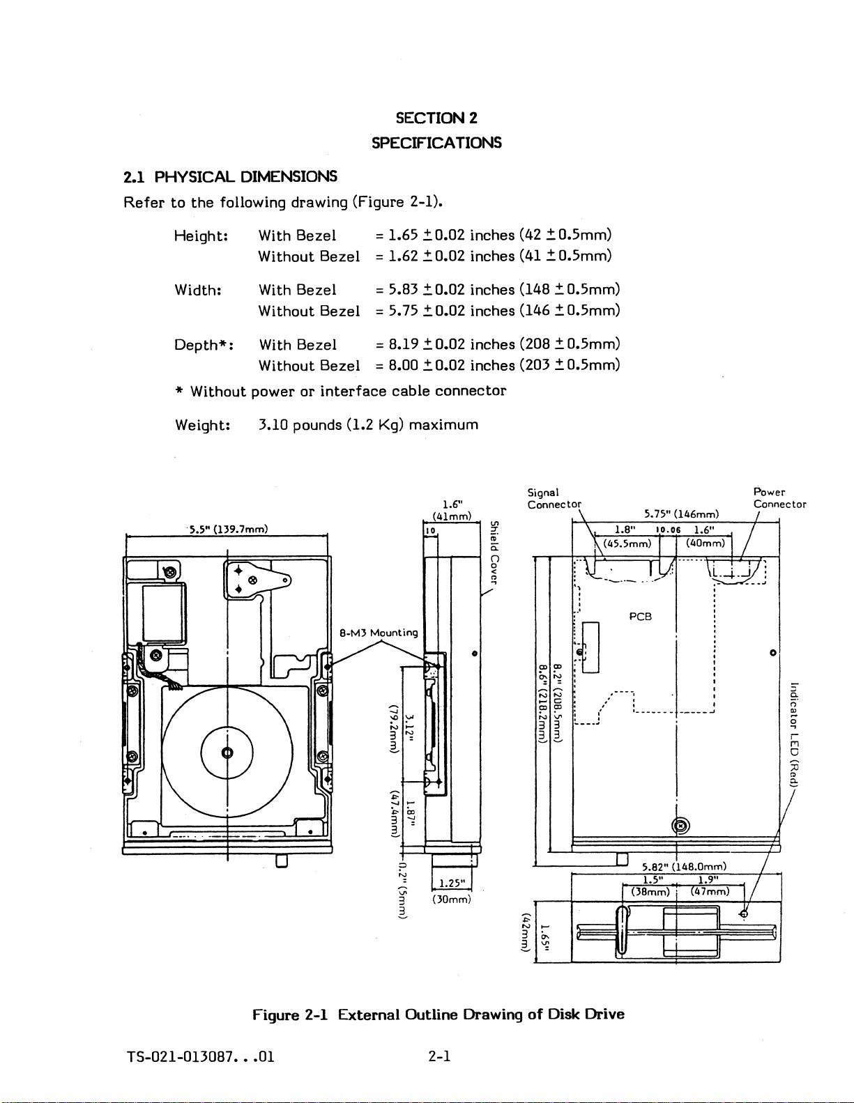
SECTION 2
SPECIFICATIONS
2.1 PHYSICAL
Refer
to
the
following drawing (Figure 2-1).
Height:
Width: With Bezel
Depth*:
* Without
Weight:
. 5.5" (139.7mm)
DIMENSIONS
With
Bezel
Without
Without
Bezel
Bezel
With Bezel = B.19
Without
power
Bezel = B.OO
or
interface
= 1.65
= 1.62
=
5.B3
= 5.75
cable
~0.02
~
0.02 inches (41 ~ 0.5mm)
~0.02
~0.02
~0.02
~0.02
connector
3.10 pounds (1.2 Kg) maximum
(41mm)
10
inches (42
inches (l4B
inches (146
inches
inches (203
1.6"
~0.5mm)
~0.5mm)
~0.5mm)
(20B
~0.5mm)
~0.5mm)
Signal
Connector
\ S.7S"
\ 1.8"
r·\L_~
,
, .
.
, .
,
..
'
(l46mm)
10.06
...
V:
1.6" /
......
\L.-l.J/]
'~
1\
(45.5mm) (40mm) I
..
_ }
PCB
.
Power
Connector
I
..
•
(JOmm)
Figure 2-1 External Outline Drawing
0>0>
"'N
= = : ·
NN
....
c
ClCl
NV,
3 3
3 3
~~
of
Disk Drive
....
_;
,
....
• I
:.--"'~
• I
11
r
(J8mm)'
___________
5.82"
(~48.0mm)
1.S"
·
I
·
•
I
:
..J
1.9"
(47mm) I /
'/
/
o
II
::
~
II)
o
-
...
2:
TS-021-0130B7
•••
01
2-1
Page 14
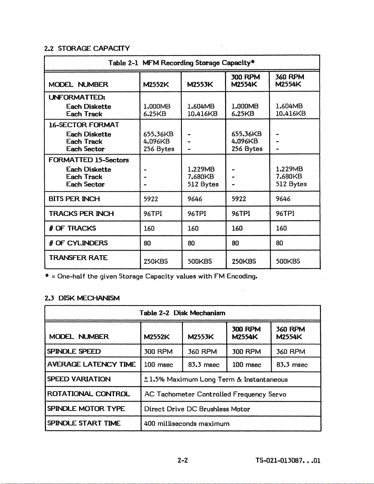
2.2 STORAGE CAPACITY
Table 2-1
MODEL NUMBER
UNFORMATTED:
Diskette
Each
Track
Each
16-SECTOR FORMAT
Diskette
Each
Each
Track
Each
Sector
FORMATTED
Each
Each
Each
BITS
PER
TRACKS
I OF TRACKS 160 160 160
15-Sectors
Diskette
Track
Sector
INCH
PER
INCH 96TPI 96TPI
MFM
Recording
M2552K
1.000MB 1.604MB
6.25KB
655.36KB
4.096KB
256 Bytes
-
-
-
5922 9646
Storage
M2553K M2554K
1O.416KB 6.25KB
-
-
-
1.229MB
7.680KB
512 Bytes
Capacity*
300 RPM
1.000MB
655.36KB
4.096KB
256·
-
-
-
5922 9646
96TPI
Bytes
360 RPM
M2554K
1.604MB
10.416KB
-
-
-
1.229MB
7.680KB
512 Bytes
96TPI
160
I OF CYLINDERS
TRANSFER RATE
*
= One-half
2.3 DISK MECHANISM
MODEL NUMBER
SPINDLE SPEED
AVERAGE LATENCY
SPEED VARIATION
ROTATIONAL CONTROL
SPINDLE MOTOR TYPE
the
given Storage
TIME
80
250KBS 500KBS 250KBS
Capacity
Table 2-2 Disk Mechanism
M2552K
300
RPM
100 msec 83.3 msec 100 msec 83.3 msec
='1.5% Maximum Long
AC
Tachometer
Direct
Drive DC Brushless Motor
80
values with
M2553K
360 RPM 300 RPM 360 RPM
Controlled Frequency Servo
80
FM
Encoding.
300 RPM 360 RPM
M2554K
Term
& Instantaneous
80
500KBS
M2554K
SPINDLE START
TIME
400 milliseconds maximum
TS"()21-D1JOB7
•••
01
Page 15
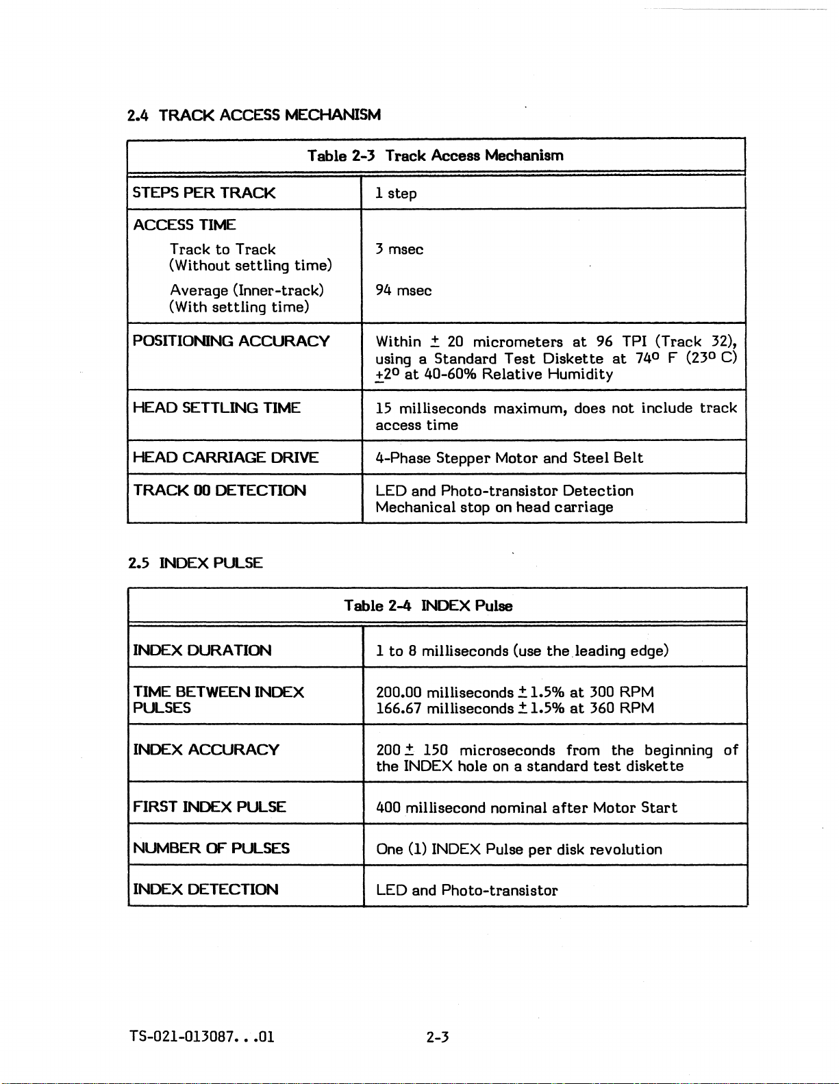
2.4 TRACK ACCESS MECHANISM
Table 2-3 Track Access Mechanism
PER
STEPS
TRACK
1
step
ACCESS
TIME
Track
to
(Without
Track 3 msec
settling
time)
Average (Inner-track)
(With
settling
time)
POSITIONING ACCURACY
HEAD SETTLING
HEAD CARRIAGE
TIME
DRIVE
TRACK 00 DETECTION
2.5 INDEX PULSE
94
msec
Within
using a Standard
.:t20
.:t
20
micrometers
Test
Diskette
at
40-60% Relative Humidity
at
96 TPI (Track 32),
at
15 milliseconds maximum, does not include
access
4-Phase
LED and
Mechanical stop on
time
Stepper
Motor and
Photo-transistor
head
Steel
Detection
carriage
Belt
Table 2-4 INDEX Pulse
740 F (230 C)
track
INDEX DURATION
TIME
BETWEEN INDEX 200.00 milliseconds
PULSES
INDEX ACCURACY
FIRST INDEX PULSE
NUMBER
OF
PULSES
INDEX DETECTION
TS-021-013087
•••
01
1
to
8 milliseconds (use
166.67 milliseconds
.:t
1.5%
.:t
1.5%
the
leading edge)
at
300 RPM
at
360 RPM
200.:t 150 microseconds from
the
INDEX hole on a
400 millisecond nominal
(1) INDEX Pulse
One
LED
and
Photo-transistor
standard
after
per
disk revolution
2-3
the
test
disket
Motor
beginning
te
Start
of
Page 16
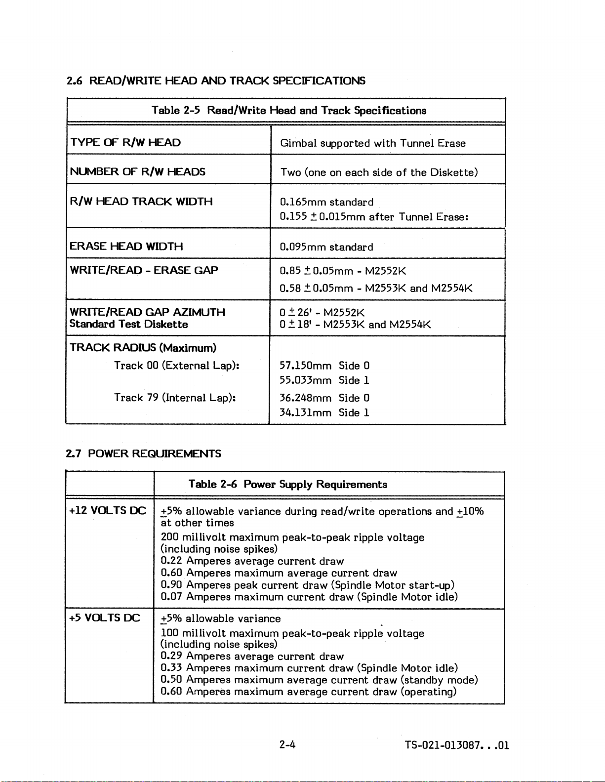
2.6
READ/WRITE .-EAD AND TRACK SPECIFICA
nONS
Table 2-5 Read/Write Head and
TYPE OF R/W HEAD
OF
NUv1BER
R/W HEAD TRACK
ERASE HEAD
WRITE/READ - ERASE GAP 0.85 !: 0.05mm - M2552K
WRITE/READ GAP AZIMUTH O!: 26' - M2552K
Standard
TRACK RADIUS (Maximum)
R/W HEADS
WIDTH
WIDTH
Test
Diskette
Track 00 (External Lap): 57.150mm Side 0
Gimbal supported with Tunnel Erase
Two
0.165mm
0.155 !:
0.095mm
0.58 !: 0.05mm - M2553K and M2554K
o !: 18' - M2553K and M2554K
55.033mm Side 1
Track
(one on
standard
0.0l5mm
standard
Specifications
each
side
of
after
Tunnel Erase:
the
Diskette)
Track 79 (Internal Lap): 36.248mm Side 0
2.7 POWER REQUIREMENTS
Table
+12
+5
VOLTS
VOLTS
DC
DC
!:5% allowable variance during
at
other
200 millivolt maximum
(including noise spikes)
0.22 Amperes average
0.60
0.90 Amperes peak
0.07 Amperes maximum
!:5% allowable variance
100 millivolt maximum
(including noise spikes) -
0.29 Amperes average
0.33 Amperes maximum
0.50 Amperes maximum
0.60 Amperes maximum
times
Amperes
2-6
Power
maximum
34.131mm Side 1
Supply Requirements
read/write
peak-to-peak
current
average
current
current
peak-to-peak
current
current
average
average
draw
current
draw (Spindle Motor
draw (Spindle Motor idle)
draw
draw (Spindle Motor idle)
current
current
operations and !:10%
ripple voltage
draw
start-up)
.
ripple voltage.
draw (standby mode)
draw (operating)
2-4
TS-021-013087
•••
01
Page 17
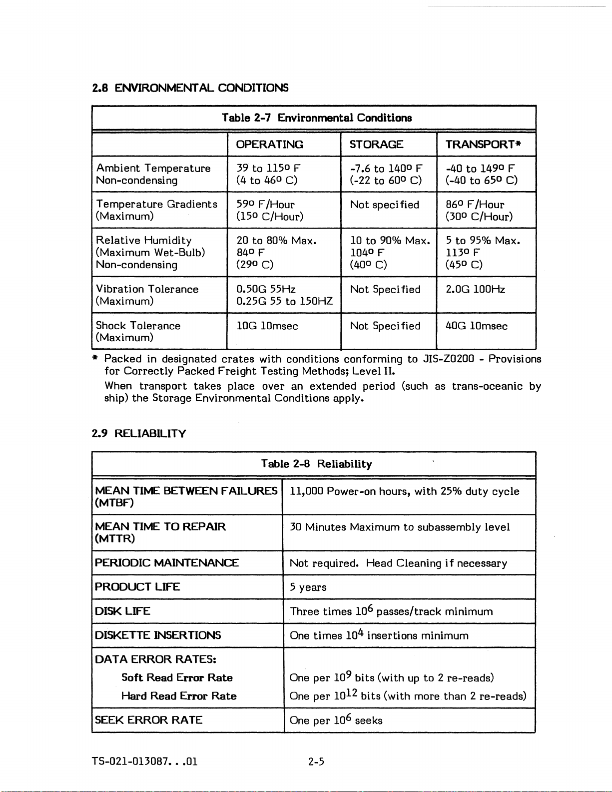
2.8 ENVIRONMENTAL CONDITIONS
Table
2-7 Environmental Conditions
OPERATING STORAGE TRANSPORT*
39
to
Ambient
Non-condensi
Temperature
Temperature
ng
Gradients
(Maximum)
Relative
Humidity
(Maximum Wet-Bulb)
Non-condensing
1150 F
to
46
0
(4
590 F/Hour
(150 C/Hour)
20
to
80%
840 F
(290 C)
Vibration Tolerance 0.50G 55Hz
(Maximum)
Shock Tolerance
0.25G
lOG 10msec
55
(Maximum)
* Packed in designated
for
Correctly
When
ship)
transport
the
Packed
takes
Storage Environmental Conditions apply.
crates
Freight
place over an extended period (such as
with conditions conforming to JIS-Z0200 - Provisions
Testing Methods; Level
C)
Max. 10
to 150HZ
to
-7.6
(-22
1400 F -40
to
600 C) (-40
Not speci fied
to
1490 F
to
650 C)
860 F/Hour
(300 C/Hour)
to
90% Max. 5 to 95% Max.
1040 F
1130F
(400 C) (450 C)
Not Speci fied
2.0G 100Hz
Not Speci fied 40G 10msec
II.
trans-oceanic
by
2.9 RELIABILITY
Table 2-8 Reliability
MEAN
TIME
BETWEEN FAILURES
(MTBF)
MEAN
TIME
TO REPAIR
(MTTR)
PERIODIC MAINTENANCE
PRODUCT LIFE 5
DISK LIFE
DISKETTE INSERTIONS
DATA ERROR RATES:
Soft
Read
Error
Hard Read
Error
Rate
Rate
SEEK ERROR RATE
11,000 Power-on hours, with
30
Minutes Maximum
Not required.
Head Cleaning
to
subassembly level
years
Three
One
One
One
One
times
times
per
per
per
106 passes/track
104 insertions minimum
109 bits
12
10
(with
bits
(with more
up
to
106 seeks
25%
duty
cycle
if
necessary
minimum
2 re-reads)
than 2 re-reads)
TS-021-013087
•••
01
2-5
Page 18
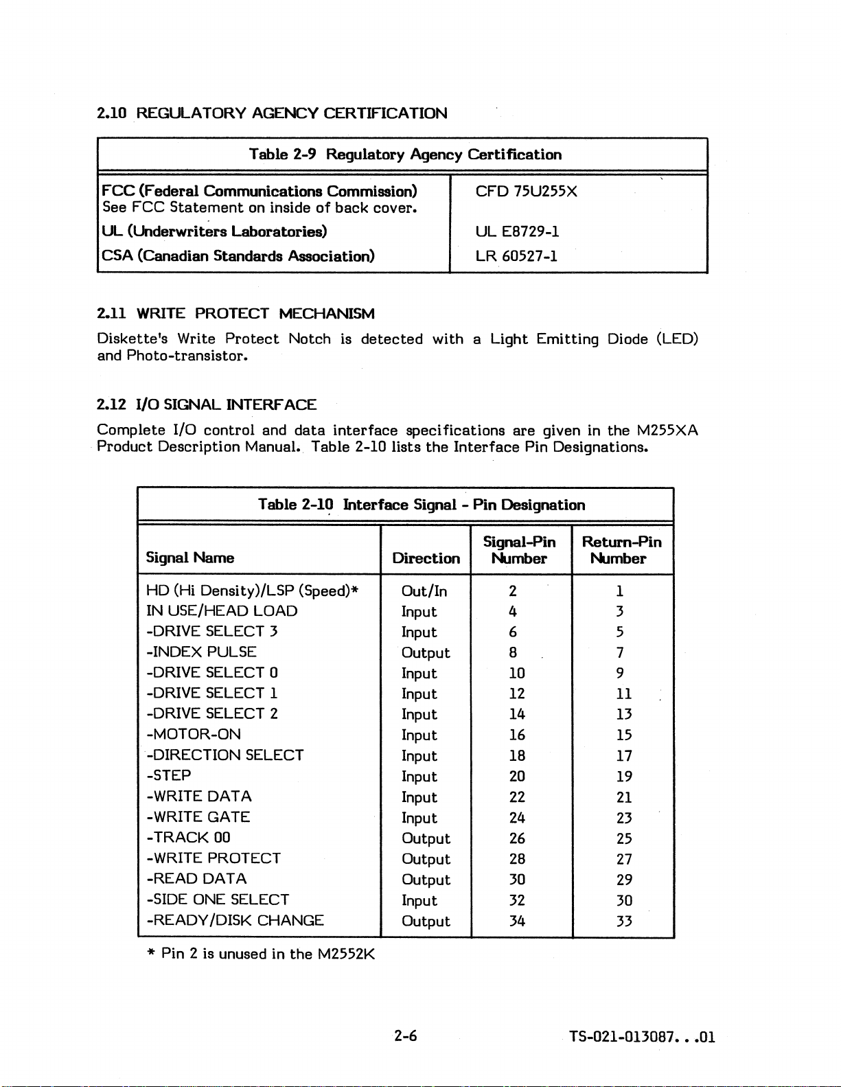
2.10 REGULATORY AGENCY CERTIFICATION
Table 2-9 Regulatory Agency
FCC
(Federal
See FCC
Communications Commission) CFD 75U255X
Statement
on inside
of
back
UL (Underwriters Laboratories)
CSA (Canadian Standards Association)
2.11 WRITE PROTECT MECHANISM
Diskette's Write
and
Photo-transistor.
Protect
Notch is
detected
2.12 I/O SIGNAL INTERFACE
Complete
Product
I/o
control
and
data
interface
Description Manual. Table 2-10 lists
Table 2-10
Interface
Signal Name
cover.
with a Light Emitting Diode (LED)
specifications
the
Signal -
Direction
Certification
UL
EB729-1
LR 60527-1
are
given in
Interface
Pin
Pin Designations.
Designation
Signal-Pin
Number Number
the
M255XA
Return-Pin
HD
(Hi Density)/LSP (Speed)*
IN
USE/HEAD LOAD
-DRIVE SELECT 3
-INDEX PULSE
-DRIVE SELECT 0
-DRIVE SELECT 1
-DRIVE SELECT 2
-MOTOR-ON
-DIRECTION SELECT
-STEP
-WRITE DATA
-WRITE GATE
-TRACK 00
-WRITE PROTECT
-READ DATA
-SIDE ONE SELECT
-READY /DISK CHANGE
* Pin 2 is unused in
the
M2552K
Out/In
2 1
Input 4 3
Input
Output
6
B
5
7
Input 10 9
Input 12
Input 14
Input 16
Input IB
Input
Input
Input
Output
Output
Output
20
22
24
26
2B
30
11
13
15
17
19
21
23
25
27
29
Input 32 30
Output 34
33
2-6
TS-021-0130B7
•••
01
Page 19
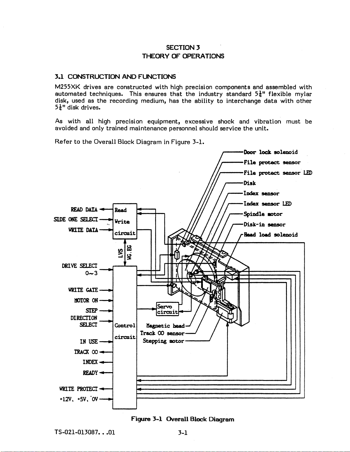
THEORY OF OPERATIONS
3.1
CONSTRUCTION AND FUNCTIONS
SECTION 3
M255XK drives
automated
disk, used
5i"
disk drives.
are
constructed
with high precision
techniques. This ensures
as
the
recording medium,
that
has
the
the
industry
ability
components
standard
to
interchange
As with all high precision equipment, excessive shock and
avoided and only
Refer
to
the
trained
Overall
maintenance
personnel should
Block Diagram in Figure
3-1.
service
the
,---Door
,---File
r----File
,--Disk
IDdex
and assembled with
5i"
flexible
data
vibration
with
must
mylar
other
be
unit.
lock
soleuoid
protect
protect
seasor
sensor
sensor
LFD
LED
T5-021-013087
•••
01
!fapetic
Track 00
~wi~~r---J
Figure
J-1
bead
sensor
OveraD Block
3-1
Diagram
Page 20
3.1.1
The
are
accuracy
Frame
frame
Assembly
assembly is
the
skeleton on which
mounted. This aluminum die
and expansion
ratio
required
cast
chassis ensures
for
stable
the
mechanisms and
the
disk drive operations.
3.1.2 Door Opening/Closing and Disk Clamping Mechanism
drive has
circuit
the
strength,
boards
The door opening/closing mechanism includes
lever,
the
the
spindle
and
end
of
collet
to
set
arm.
the
enters
ensure
set
the
The disk clamp mechanism (Collet) is moved
arm.
the
When a
opening in
disk is
accurately
diskette
the
is
center
clamped into posi tion.
3.1.3 Spindle Mechanism
The disk
spindle
rotating
motor
a service life
rotates
temperature
into
the
at
300 or 360 RPM and maintains a
fluctuations, by using feedback signals from an AC
motor.
The spindle and
the
disk and
to
and disk come into
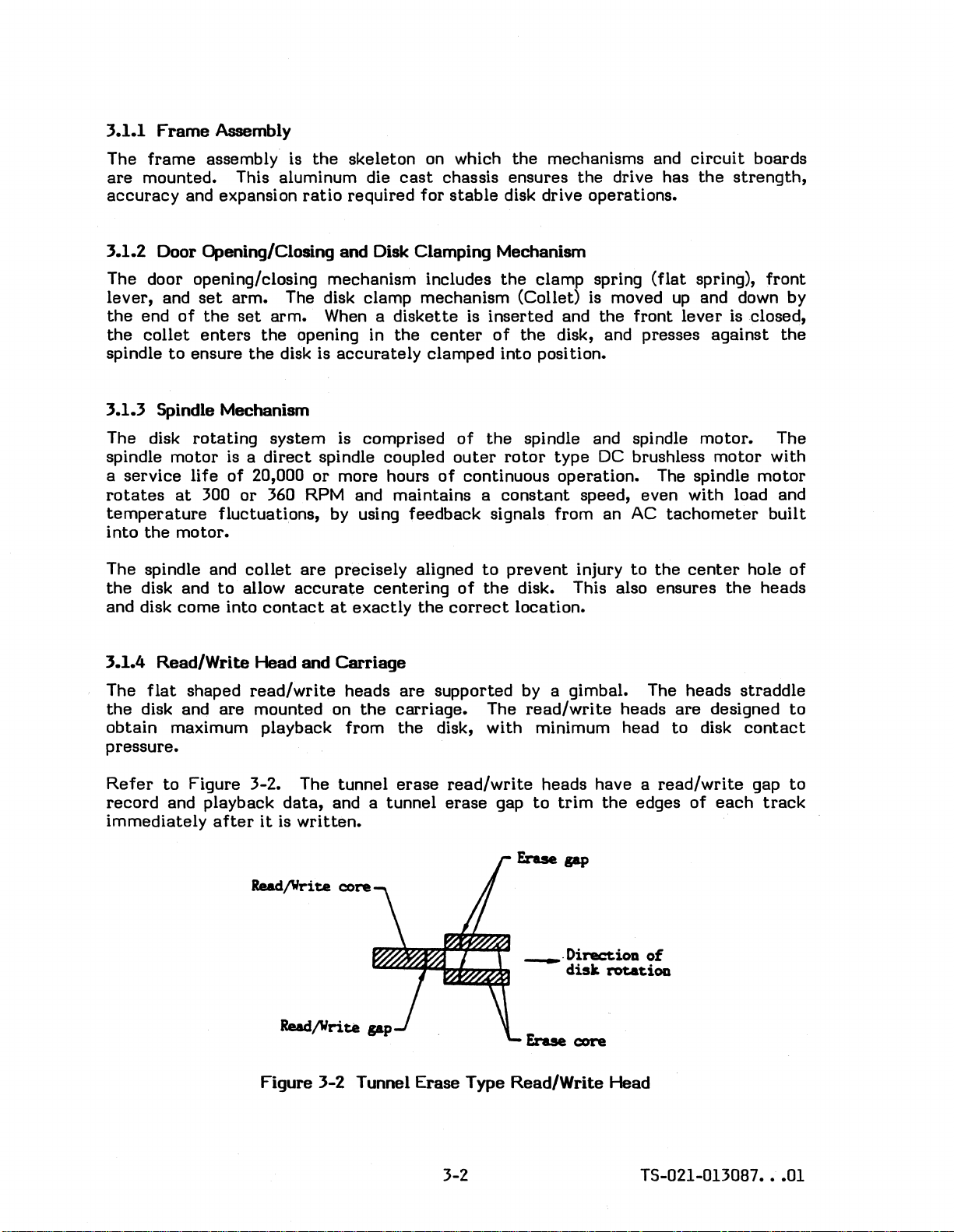
3.1.4
The
the
obtain
Read/Write
flat
shaped
disk and
are
maximum playback from
system
is a
direct
of
20,000
collet
allow
contact
Head
read/write
mounted on
is comprised
spindle coupled
or
more hours
are
precisely aligned
accurate
and
centering
at
exactly
Carriage
heads
the
of
outer
of
continuous operation. The spindle
of
the
correct
are
supported by a gimbal. The heads
carriage.
the
disk, with minimum head
pressure.
the
clamp spring
inserted
of
the
rotor
constant
and
the
the
disk, and presses
spindle and spindle motor. The
type
DC brushless
speed, even with load and
(flat
front
spring),
up
and down by
lever
against
motor
tachometer
to
prevent
the
disk. This also ensures
injury
to
the
center
location.
The
read/write
heads
are
to
designed
disk
front
is closed,
the
with
motor
built
hole
of
the
heads
straddle
to
contact
Refer
record
to
Figure 3-2. The tunnel
and playback
immediately
data,
after
it
is
Rea.d/Write core
erase
and a tunnel
written.
read/write
erase
gap
heads have a
to
_.Direc:tioa
Erase
Figure 3-2 Tunnel Erase Type Read/Write Head
3-2 T5-021-013087
trim
disk
core
the
edges of
of
rotation
read/write
each
gap
track
•••
to
01
Page 21
3.1.5 Seek Mechanism
The seek mechanism is
mechanism includes a
carriage
stepping
The stepping
by single-phase
slides along two guide
motor
via
motor
the
utilizes
excitation
built
steel
steel
around a stepping
band, guide
shafts
band.
a 4-phase
and
it
rotates
track.
Parallelism
shaft
the
and
chassis,
and designed
3.1.6 Write
This
detector
They
detect
and
distance
capstan,
steel
to
counteract
Protect
is comprised
the
presence
are
assembled
band,
carriage,
Detection
between
the
expansion
of
a Light
or
absence
the
to
and
When a disk with a covered notch is
operation
protected,
The LED is mounted on
sensor is mounted on
of
the
even
write
if a write
the
circuits
is
prevented.
command is given.
the
spindle
write
protect
motor
shaft
and
and is
construction.
one
step
shaft
close
and disk
tolerances.
associated
of
the
disk.
Emitting
of
a wri
te
inserted,
Previously
motor
circuit
circuit
card
with a
read/write
connected
capstan
head
to
the
This stepping
0
(1.8
to
)
center
move
lines,
Temperature
items
have
been
Diode (LED) and
enable
the
light
notch
path
on
is broken and any
written
card
and
the
assembly.
(pulley). This
carriage.
capstan
motor
the
carriage
as
well as
The
of
the
is driven
one
the
expansion
carefully
studied
photo-transistor.
the
disk
jacket.
data
is
thereby
photo-transistor
of
3.1.7 Track 00
The Track 00
(photo-interrupter)
to
the
drive's
Detection
detector
is comprised
and a mechanical
circuitry
whenever
position (Track 00). The mechanical
beyond Track 00 during a
If
the
head
carriage
received,
the
edge
calibrate
To
move
there
of
the
several
is enough margin provided
opening in
the
head
steps
seek
is
at
carriage
beyond
operation
its
the
disk.
the
innermost
(return
maximum
M255XK, which has 80 cylinders,
calibrate
3.1.8 Index
An
LED and
the
spindle
disk
at
track
Detection
each
motor
00.
photo-transistor
time
circuit
the
hole passes
board and
are
mounted in
the
assembly.
of
an LED and photo
stop.
the
stop
to
the
The
photo-interrupter
head
carriage
prevents
or
when power is initially
track
it
track
position, and a
to
ensure
to
Track 00), command
number.
move outward 84
the
drive
detector.
photo-transistor
transistor
provides a signal
is
at
the
outermost
the
head
that
to
carriage
the
For
to
detect
example,
turned
step-in
heads will
86
from moving
on.
command is
not
the
carriage
command a
steps
the
to
Index hole in
The LED is mounted on
is mounted on
the
sensor
assembly
track
reach
to
have
it
the
block
TS-021-013087
•••
01
3-3
Page 22
3.1.9 Diskette Inserted Detection
The
diskette
the
disk drive.
The
diskette
assembly (photo-interrupter). This
drive's circuitry whenever a
3.1.10 Head Load Mechanism
inserted mechanism
inserted
detector
diskette
detects
is comprised
the
presence
of
photo-interrupter
is
inserted
into
or
absence
an LED and photo
provides a signal
the
drive.
of a diskette
in
transistor
to
the
The head load mechanism extends
diskettes
when necessary.
The head load mechanism is comprised
assembly, and associated
3.1.11 Door Lock Mechanism
The door lock mechanism locks
to
prevent
The door lock mechanism is comprised
and associated
3.2 CIRCUIT CPERATIONS
The drive's
by
allowing them
the
door from being opened, and causing damage
parts.
electronic
Read/Write
Control
Circuits
to
parts.
circuitry
Circuits
- explained in paragraph 3.2.2.
is comprised
- explained in paragraph 3.2.1.
the
come into uniform
the
front lever during
of
service life
of
the
head load solenoid,
the
door lock solenoid,
of
three
of
the
read/write
contact
major sections:
all
read
or
with each
or
the
lost
write
of
data.
eject
heads and
other,
arm
operations
only
lifter
assembly,
Spindle Motor Servo
The Read/Write, and Control
the
Servo
3.2.1
The Read/Write
circuits,
LSI
Figure 3-3.
circuits
are mounted on
Read/Write Circuits
circuits
and associated sections. These various
control
circuit.
Circuits
include
A
partial
- explained in paragraph 3.2.3.
circuits
the
read
are
mounted on
spindle motor board.
circuits,
diagram
of
write
sections
this
circuits,
LSI
control
the
are
main
circuit
low voltage
accommodated in one
circuit
T5-021-013087
board and
detection
is
shown in
••.•
01
Page 23

Rud,lVrite coil
Erase
coil
eo.on
(center
tap)
TPI
TP2
IP4
IPS
tP'3
J
GIlD
-----------AO
l....I'lrn....t.....L..I Oiode
SIDE
1
1'-r-r"T"T"""'1"T'-r-'
I.
Iwitch
~:f:ii
~:
I
I
I
I
L
____________
The read
detector,
circuits
drop
detector
includes a pre-amp, low pass .filter,
Al
At
F'-----1
UD
0.1
and
Urite
driver
VD
_
Figure 3-3
read
output
AO-
Read/Write
driver.
VGSO
-
Circuits
Low
YOltap
cletectioo
circuit
---------~
differential
LYS
amp, peak
I
I I
I
I
I I
I
I
LJ
Refer
signals induced into
amp (a
pass
The
simultaneously applies
difference
The
detector,
to
the
read
subtraction
filter.
The amplified signal then goes
differential
in
the
output
from
the
bad influence
circuit
the
timing
chart
in Figure 3-4. The micro-voltage level
Read/Write head during playback is amplified by a
amplifier) and spurious noise components
to
the
differential
amp
shifts
frequency components. The signal is
the
differential
the
the
proper amount
of
the
playback signal
of
compensation in
amp is
converted
saddle (which
to
the
further
into a square wave by
occurs
zero
during playback
frequency signal component approximately 125k Hertz) is
detector.
The
read
data
when Read
Gate
TS-021-013087
signal is driven
is
true.
•••
01
out
of
the
3-5
drive by
the
read
pre-
are
removed by a low
amp.
crossover position and
accordance
with
the
amplified.
the
peak
of
the
low-
eliminated
output
by
driver
the
drop
circuit,
Page 24
tfagnetizatiou
of
disk
-I
~
1
......
1--1
1--
Pre-up
Pre-up
Differential
Differential
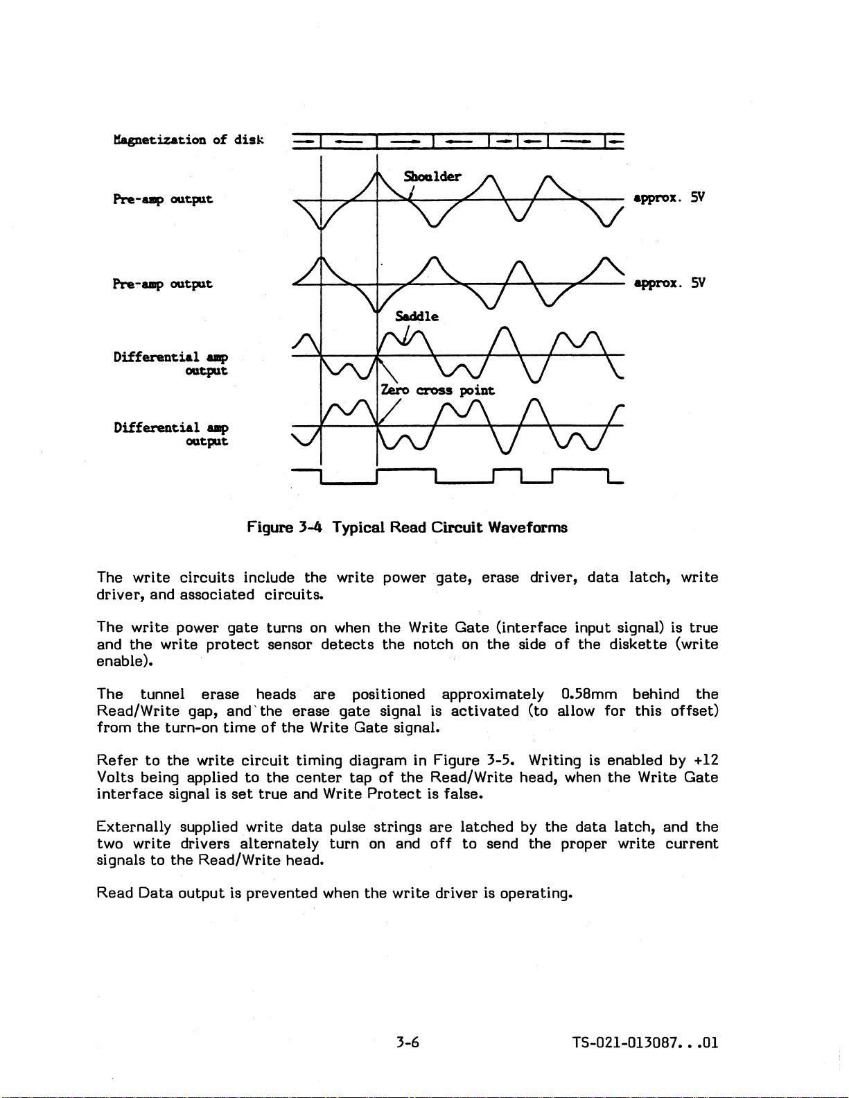
The
write
driver,
and
OQtpllt
OQtpllt
amp
OQtp1t
up
OQtpllt
circuits
associated
Figure
include
circuits.
,L..-_
3.04
the
....
Typical
write
Read
power
Circuit
gate,
Waveforms
erase
driver,
L
data
latch,
write
The
write
and
the
enable).
The tunnel
Read/Write
from
Refer
Volts being applied
interface
Externally
two
write
signals
Read
write
the
to
to
Data
power
protect
erase
gap,
turn-on
the
write
signal is
supplied
drivers
the
Read/Write
output
gate
and'the
time
turns
sensor
heads
of
the
circuit
to
the
set
true
write
alternately
head.
is
prevented
on when
detects
are
erase
Write
timing diagram in Figure 3-5. Writing is
center
and Write
data
pulse
turn
when
the
the
positioned
gate
signal is
Gate
signal.
tap
of
Protect
strings
on and
the
write
Write
the
Gate
notch
approximately
activated
Read/Write
is
false.
are
off
driver
(interface
on
the
latched
to
send
is
operating.
input signal) is
side
of
the
0.58mm behind
(to
allow
head, when
by
the
data
the
proper
diskette
for
this
enabled
the
Write
latch,
write
true
(write
the
offset)
by
+12
Gate
and
the
current
3-6
TS-021-013087
•••
01
Page 25
WRIIE
GAIE
input
signal
--,
i
(lDterDal)
Erase
SIDE
WRItE
Data
Write
Hagoatization
gate
ONE
DAtA
latch
driver
WRITE
sigaal
SELECI
input
output
GATE
sigDal
outplt
of
disk
J;J/7~~:=I//J/////#ql/jt-----+-r-
.
Wrlte
__
-JV///'
-.-----
--.1.--------II------------L-
driver
iw»n»»,""",""
Erase
area
driver
of
operatlOD . .
b»»m;m;mmm%VZ1
area
--+-------,-
of
operation
'///.11..-
Erase
off
delay
%I-I-I~I-I-I-I-t3-1-~
Previous
-.petization
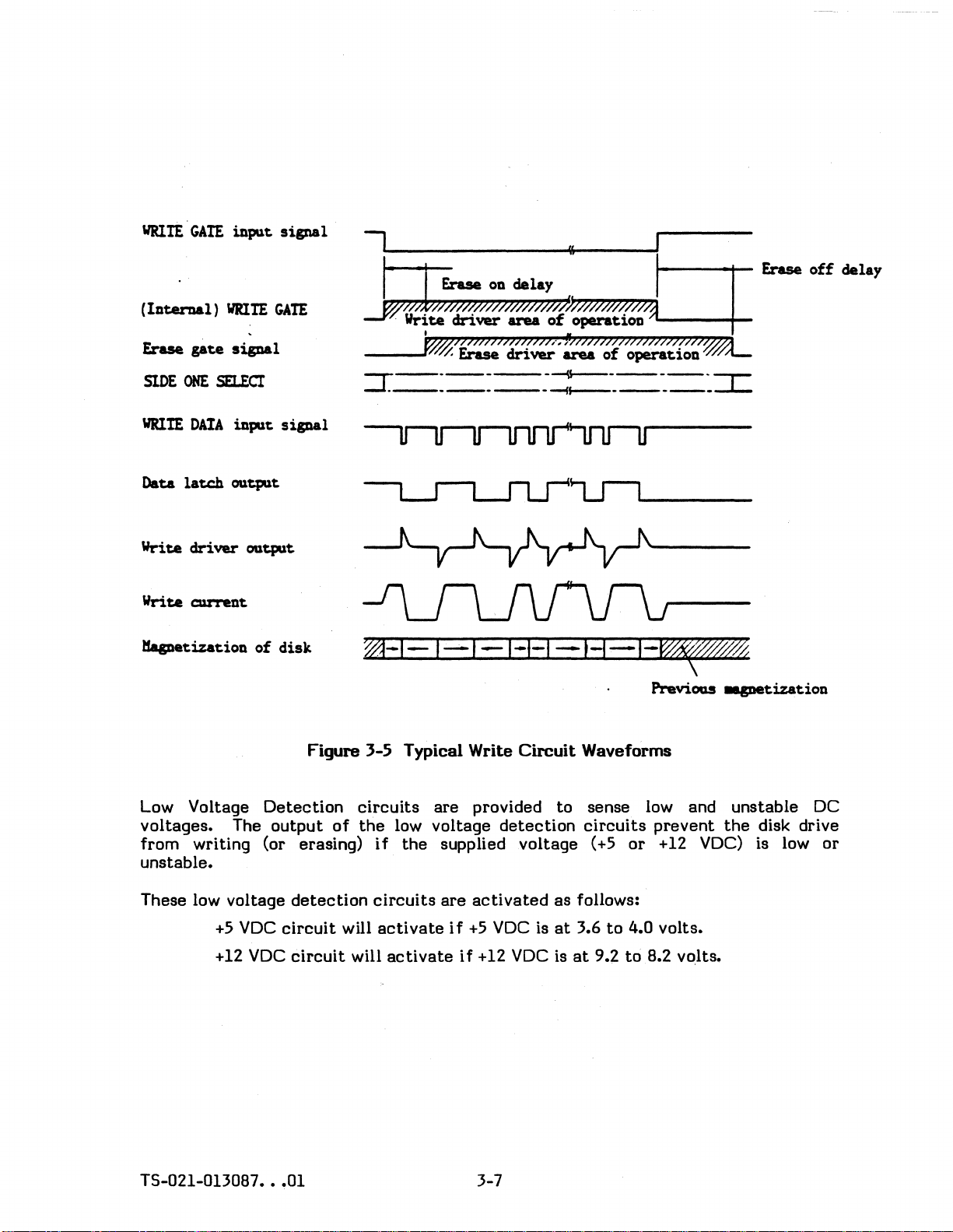
Figure 3-5 Typical Write
Low Voltage
voltages. The
Detection
output
of
from writing (or erasing)
unstable.
VDC
•••
detection
circuit
circuit
01
will
will
These low voltage
+5
VDC
+12
TS-021-013087
circuits
the
low voltage
if
the
circuits
activate
activate
Circuit
are
provided to sense low and unstable DC
detection
supplied
are
if
+5
if
voltage
activated
VDC
+12
VDC
Waveforms
circuits
(+5
as follows:
is
at
3.6
is
at
to
9.2
to
prevent
or
+12
4.0 volts.
8.2 volts.
the
VDC)
3-7
disk drive
is low or
Page 26

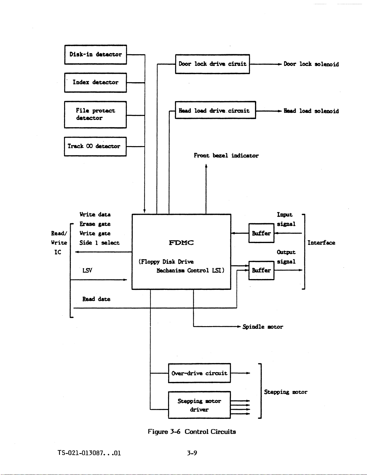
3.2.2
Control
Circuits
Refer
All
primarily on
The
output
to
Figure
control
control
signals
the
circuits
Detectors·
protect
The individual
Drive
Select
drive's
These
circuits
Jumper
corresponding Drive
Head Load
determines
Read/Write heads
Write/Erase
through
recording on
Gate
to
interface
correspond
3·6.
circuits
are
mounted on
the
Control IC (one chip).
to
the
circuit
select
receive
Read/Write IC and
All
detectors
card,
detectors
and Indicator
status
operate
data
from
the
the
(photo-transistors)
disk-in senSor assembly,
are
described in paragraph 3.1.
Gate
Circuits
and also when
in conjunction with
(Position 0 through 3 which
Select
Gate
the
Gate
the
Write and Erase coils (in
the
- This
set
to
load. . .
Circuits
disk. . These
signal. Erase
to
the
beginning and ending
interface
of
conditions
circuit,
- These
circuits
current
signal.
circuits
main
circuit
card
various sensors and
interface.
are
mounted on
or
track
the
- These
Front
the
are
position
set
Bezel
by
circuits
indicator
in conjunction with
that
is delayed
must be
determine
the
operate
of
write
present
when
selected
Read/Write Head) for
in conjunction with
(the
required period
current.
assembly and
circuits
and provide
either
the
are
write
00 sensor assembly.
determine
of
the
the
user) and
selection
to
current
will
Drive
cause
will flow
the
the
be
lit.
Select
the
jumpers,
the
Write
of
time)
Spindle Motor
Gate
- This
motor.
Ready
Detector)
rotational
Detect
and
speed.
Circuits
sets
the
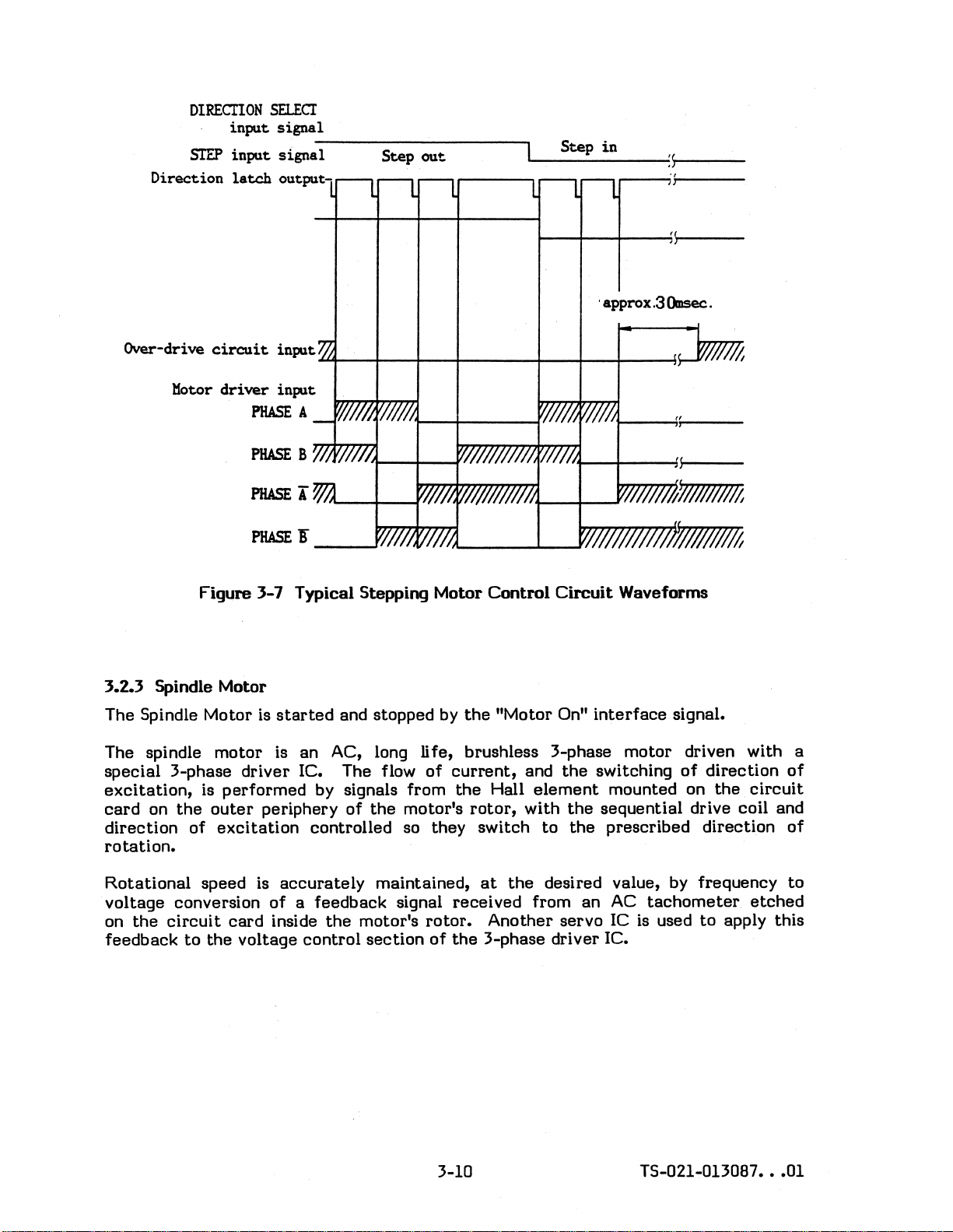
Stepping Motor Control
over-drive single
determine
the
The timing
shot
circuit
movement
chart
in Figure 3-7 shows
waveform.
output
The
drive
circuit
During this
high level
carriage.
stepping
position (and
the
motor
of
the
for
the
time
+12V
of
torque is available
After
motor
centering
coil for holding
to
lower power
coil).
output
- This
circuit
circuit
Ready signal
Circuits
and
of
the
Stepping Motor.
Step pulse
prescribed
is
activated
is
requirements
determines
receives
true
when
- These
the
circuits,
Direction and Step
typical
generator
time
on
for
circuit
(approximately 30 milliseconds).
the
stepping
seeking and
completed,
the
head
carriage
and excessive heating
the
speed
of
Index .pulses (from
the
disk
reaches
in conjunction with
interface
stepping
motor
control
'.
turnQ
centering
+5V
on
the
motor
coil and a
is applied
at
the
the
to
correct
the
the
its
over-
head
the
of
spindle
Index
correct
the
signals,
.
3-8
TS~21-013087
•••
01
Page 27
....---4
Door
l.ocJt
drive
cinait
t----
Door
lock
IOleooid
Read
Write
IC
lDdu
File
detector
track
Write
...
Erue
Write
I
Side 1 select
l5V
detector
protect
00
detector
data
gate
gate
(Floppy
tfechaoisll
FDMC
Disk Drive
Q)otrol
Fl'ODt
bezel
LSl)
iadicator
Buffer
Buffer
r--e'
~--1IMd
IDPUt
si&Dal
OIltplt
si&Da1
load soleDOid
.
IDterface
Read
date
..
TS-021-013087
•••
01
I-----1Over-drive
Stepping
driver
Figure
3-6
Control
3-9
circuit
mtor
Circuits
1---
Spindle
.
.
IIOtor
Stepping
.
IDOtor
Page 28
DlRECIlON
STEP
Direction
SELECI
input signal
input signal
latch
----------~------~
output-
Step
out
Step
in
~--------~:~~----
,...---...,';i-------
Over-drive
Motor
circuit
driver
PHASE
PHASE
PHASE
PHASE!"
Figl.lre 3-7 Typical Stepping Motor
3.2.3 Spindle Motor
The Spindle Motor is
The spindle
special
excitation,
card
on
direction
motor
3-phase driver IC. The flow
is
performed
the
outer
of
periphery
excitation
rotation.
input
~--~---~---+------~--~--4-----1~
input
A
8
I
__
started
is an AC, long Ii
by signals from
controlled so they switch
~
and stopped by
fe,
of
of
the
motor's
Control
the
"Motor On"
Circuit
brushless 3-phase motor driven with a
current,
the
rotor,
Hall
and
the
element
with
the
to
the
; approx.3
Omsec.
"
Waveforms
interface
switching
mounted on
sequential drive coil and
prescribed direction
signal.
of
direction
the
circuit
of
of
Rotational
voltage
on
the
circuit
conversion
feedback
speed is
to
the
of
card
voltage
accurately
maintained,
a feedback signal
inside
the
control
motor's
section
at
the
desired value, by frequency
received
rotor.
of
the
3-phase driver IC.
from an AC
tachometer
Another servo IC is used
to
3-10 TS-021-013087
to
etched
apply this
•••
01
Page 29
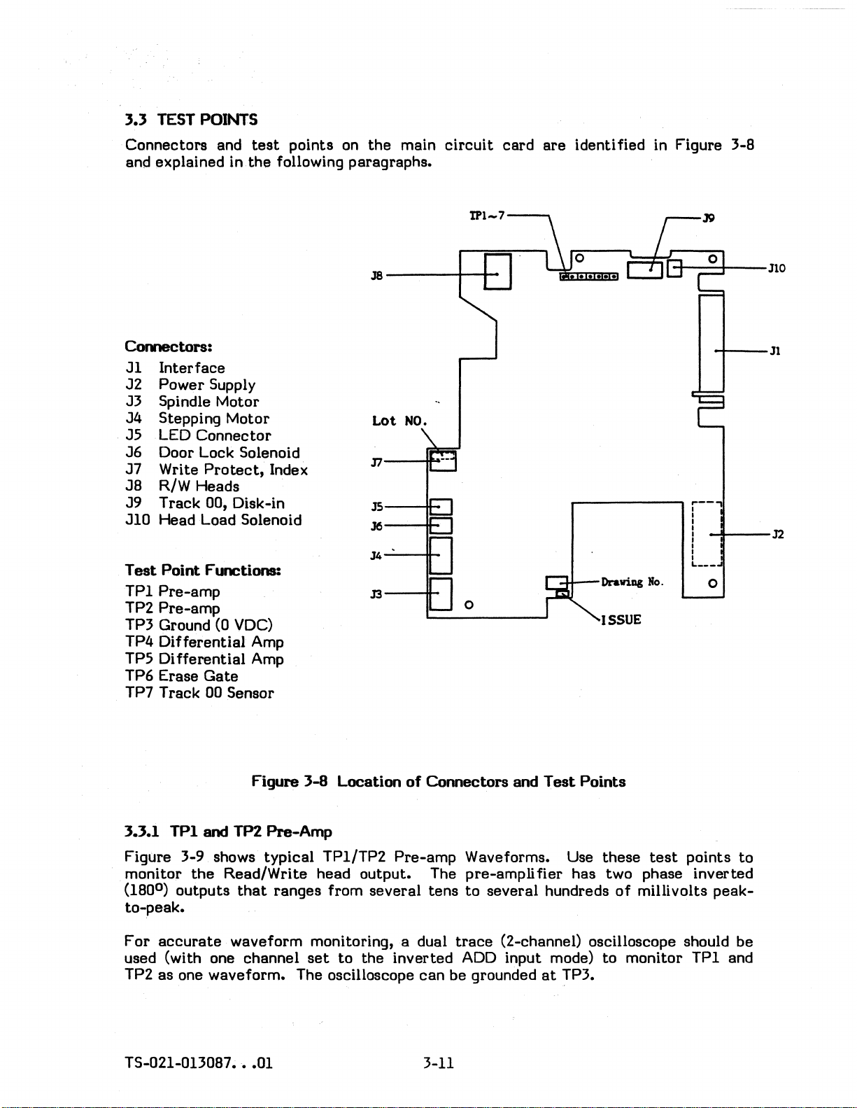
3.3 TEST POINTS
Connectors and
and explained in
test
the
Con1ectors:
Jl
Interface
J2
Power
Supply
J3 Spindle Motor
J4
Stepping Motor
J5
LED
Connector
J6
Door Lock Solenoid
J7
Write
J8
R/W Heads
J9
Track 00, Disk-in
JI0
Head Load Solenoid
Test
Point
TPI
Pre-amp
TP2
Pre-amp
TP3 Ground (0
TP4
Differential
Di
TP5
TP6 Erase
Protect,
FlD!tions:
VDC)
fferential
Gate
Amp
Amp
TP7 Track 00 Sensor
points
on
the
main
following paragraphs.
J8---~-+-
Lot
NO.
Index
circuit
card
are
identified in Figure 3-8
-t---+--Jl0
,..---------,
Draviag
ISSUE
No.
-+---Jl
r--"
I
I
I
I
-+--32
I
I
L
__
_
I
o
Figure
3.3.1
Figure 3-9 shows
monitor
(180
TPI
0
)
outputs
and TP2
Pre-Amp
typical
the
Read/Write head output. The pre-ampll
that
ranges
to-peak.
For
accurate
waveform monitoring, a dual
used (with one channel
as
TP2
TS-021-0n087
one waveform. The oscilloscope
•••
01
3-8
Location
TP1/TP2
from
set
to
Pre-amp
several
the
inverted
of
Connectors
tens
trace
ADD
can
be
3-11
and
Test
Points
Waveforms. Use
fier
to
several
hundreds
these
test
has two phase
of
mUll volts
(2-channel) oscilloscope should
input mode)
grounded
at
TP3.
to
monitor
points
inverted
peak-
TPI
and
to
be
Page 30

3.3.1
TPI
and TP2 Pre-Amp (Continued)
TP1 and TP2
signal.
3.3.2 TP3
Used for grounding
prevent
3.3.3 TP4 and TP5
These
The
(180
to-peak.
shorting nearby
test
Differential
0
outputs
)
are
Ground
points
Amp (like
that
Figure 3-10 shows
~
available for checking
Figure
Differential
are
3-9
TPl/TP2
test
instruments. Use
test
points.
Amp
used
to
monitor
the
Pre-Amp and 2nd Amp) also has two 'phase inverted
ranges from
typical
Typical Pre-Amp Waveform
several
TP1/TP2
/\
the
characteristics
care
the
output
tens
to
several
Differential
/"f\
of
the
Read/Write
when connecting a probe
from
the
Differential
hundreds
Amp Waveforms!
./\
A
of
millivolts
head
to
TP3
to
Amplifier.
peak-
Figure 3-10 TP4/TP5 Typical
For
accurate
used (with one channel
TP5 as one waveform. The oscilloscope can be grounded
TP4 and TP5
head and amplifiers, and for checking
3.3.4 TP6
Figure 3-10 shows a typical TP6 Waveform.
at
the
low level. TP6
On
Delay
Off
Delay
WRIIE
GAIE
waveform monitoring, a dual
set
to
the
are
available for checking
Erase
time
time
Gate
is
used
to
check
= 262 ±24 microseconds
= 776 ±24 microseconds
input signal
Erase
gate
On
delay
inverted
track
Differential
the
alignment.
Erase
at
1MB
at
1MB
trace
Gate
(2-channeI) oscilloscope should
ADD
input mode)
overall
Current
to
Write
(194 ±24 microseconds
(524 ±24 microseconds
Off
deJ..y
Amp Waveform
to
monitor TP4 and
at
TP3.
operation
is flowing
Gate
of
'in
delay
the
the
read/write
erase
a,t
1.6MB)
at
1~6MB).
head
..
be
Figure
3;..11
TP6 Typical
}-12
Eraae
Gate
Waveform
TS-021.013087
•••
01
Page 31

3.3.5
TP7
Track
00
Sensor
Figure
detects
this
Note:
3-12 shows a
when
signal is Low only when
Track
phase
waveform
the
00
for
Track
00
typical
head
carriage
the
output
the
variation
signal
stepping Motor is
is
not
sensor
track
Figure
3-12 TP7
Track
00
is
at
Track
head
is
becomes
constant.
02--J
Track
waveform.
00. Like
at
or
near
True (low level) while
excited.
The
track
Because
'------
the
00.
~track
00
Detect
Waveforms
Track
Track
of
this,
00
photo-transistor
00
interface
the
basic
the
timing
(m
level)
00
signal,
excitation
of
the
TS-021-0130B7
•••
01
3-13
Page 32

Page 33

4.1 PERIODIC MAINTENANCE
SECTION 4
MAINTENANCE
When used
replacing
provides additional information on cleaning
4.Ll
Table 4-1
The paragraph number, listed under
additional information
The
minutes, with
about 10 minutes
Inspection and Adjustment
time
at
a normal
parts,
lists
required
Item
Collet
Bail - Inspection and Adjustment
Disk-in Sensor - Inspection
Write
and lubricating should
the
items
to
the
exception
to
perform.
Table 4-1 Inspection and Adjustment
Assembly - Centering Adjustment
Protect
rate,
that
or a step-by-step
perform
Senor -Inspection
periodic maintenance such as cleaning, adjusting,
Items
may require inspection,
the
of
each
the
item
Track Inspection and Adjustment - which
not
removal and
be
required
the
read/write
"Refer
To" column in Table 4-1, provides
listed in Table 4-1 is approximately 5
for
5 years.
heads.
replacement
replacement
Items
Paragraph
or
adjustment.
procedure.
Refer
4.4.1
4.4.2
4.4.3
4.4.4
To
4.3
takes
Disk Speed - Inspection and Adjustment
Head
Asymmetry - Inspection and Adjustment
Read Level - Inspection
Resolution - Inspection
Track
Track 00 Sensor - Inspection and Adjustment
Index Burst - Timing, Inspection and Adjustment 4.4.12
Head Load - Inspection and Adjustment 4.4.13
Door Lock Insp,:,ction 4.4.14
4.1.2 Field
Table 4-2
wear
or
Table 4-2, provides a
Refer
item
in
to
the
Contact
- Inspection and Adjustment 4.4.10
Replaceable
lists
the
breakage.
the
Maintenance
disk drive.
- Inspection and Adjustment
Items
field
The paragraph number,
replaceable
step-by-step
Precautions
items
listed
removal and
given in paragraph 4.2 prior
that
may require
under
replacement
replacement
the
"Refer
procedure.
4.4.5
4.4.6
4.4.7
4.4.8
4.4.9
4.4.11
due
To" column in
to
replacing any
to
TS-021-013087
•••
01
4-1
Page 34

Table 4-2 Field Replaceable
Items
Item
Head
Carriage
Stepping Motor
Steel
Band Assembly JA4-5674
Part
Number
Replacement
Interval
Assembly JA3-5321 7,000 Operating Hours
or
5 X 10⁶ Seeks
J3-5295
5
5
X 10
X 10
6
Seeks 4.5.2
6
Seeks
Refer
4~5.1
4.5.2
Spindle Motor J3-5294 20,000 Operating Hours 4.5.3
Collet
Sensor
Main
Write
Front
Front
Clamp
LED
Note
Note
Assembly JA3-5265
Card
Assembly JA4-5717
Circuit
Protect
Bezel Assembly
Lever Assembly
Cam
Circuit
1: Obtain
2:
Card
Card
Note 1
JA4-5715 If
JA4-5207 If
JA4-5708
Assembly JA4-5698
Card
Front
order
replacement
Bezel and
other
colors with a color drawing number.
JA4-5716 If
part
Front
If
If
If
If
If
number from
Lever
Assembly
defective
defective
defective
defective
defective
defective
defective
defective
the
old
part
Circuit
numbers
Card.
are
4.5.4
4.5.5
4.5.6
4.5.7
4.4.8
4.4.9
4.4.10
4.4.11
black
To
items,
for
4.1.3 Tools Required
Table 4-3
mentor
list
the
adjustment
Measuring Instruments: Exerciser
Maintenance
tools
that
procedure.
Table
may
be
4-3
Trace
Dual
34-pin
AP
Intraconnector
Products
Relative
required to
perform
Maintenance Tools
(AVA
409
or
equivalent)
Oscilloscope
Adaptor
Part
Number 922576-34-1
Humidity Gauge
Hand Tools: Phillips Screwdrivers (M2.6 and
Flat
Blade Screwdriver (small and medium)
Set
Allen Wrench
(1.5mm
Tweezers, Needle Nose
flat)
Pliers
Soldering Iron and Solder
Fine Cleaning Brush
an inspection,
M3)
and Wire
Cutters
replace-
TS-021-013087
•••
01
4-2
Page 35

Table
4-3 Maintenance Tools (Continued)
D;.skettes:
(Recommended)
Maintenance Supplies:
Special
4.2 MAINTENANCE PRECAUTIONS
Ensure
Jig:
the
following precautions
Commercially available Work/Scratch
(M2552K
Commercially available Cleaning
(Dysan = 802944)
Read Level
Alignment
(M2552K = Dysan 206-31, M2553/54K = Dysan 206-34)
Anhydrous Alcohol (Ethyl Alcohol)
Cotton
Screw Lock Liquid
Epoxy Adhesive
Lubricating Oil (Kanto Kasel 946P, or equivalent)
Light Oil (Nippon Koyu HH-17,
MAX
Media Jig (Jig
are
Diskette
= Dysan 802067, M2553/54K = Dysan 802914)
Diskette
Diskette
Diskette
Gauze
or
equivalent)
D)
observed whenever working on
the
disk drive.
4.2.1 Screw Torque
Unless otherwise specified,
torque values listed in Table 4-4.
Screw Size
M3
4.2.2 Screw Lock
Use screw lock
1.
When
lock liquid
2. Before replacing a
three
as
speci fied below:
making an
off
the
threads.
adjustment,
setscrew
all
Table
M2
M2.6
M3
setscrew
setscrew
screws
4-4 Screw Size and Torque
and hole
are
tightened, according
Torque
11 Inch Pounds
24
Inch Pounds
33
Inch Pounds
24
Inch Pounds (4.5 Kilograms cm)
remove
(or any screw), apply screw lock liquid
the
holding
as
completely
(2
Kilograms cm)
(4.5
(6
Kilograms cm)
setscrew
as
possible.
to
their
Kilograms cm)
and
clean
size,
old
to
the
to
the
screw
first
3.
When
TS-021-013087
replacing a screw or
•••
01
setscrew,
tighten
4-3
it
to
the
designated torque.
Page 36

4.2.3. Handling Connectors
Handle connectors as speci fied below:
Off
Always turn power
Do not apply excessive
Remove/insert each connector
before inserting
force
to
the
by
or
removing a connector.
cable
pulling/pushing in a
or
post pin.
straight
manner.
4.2.4
Overall
Diskette
Set
Additional
Error
Perform
when inspecting, adjusting
not include
perform a window margin
Never use a
Jumper Selections
Set Drive
ble with
OSRSTR
.
MS
Ii
.
MM
Maintenance
Test
the Inspection and Adjustment procedures given in paragraph 4.4
data
Read/Write checks,
defective
Select
the
(DSO
test
system, as given below:
Precautions
or
replacing
test
to
work,
or
through
PC/AT
ensure
test
diskette
DS3)
and
CONfIGURATION
parts.
connect
data
Procedures in paragraph 4.4
the
drive
integrity.
during a maintenance
all
jumper selections
(MOVEABLE)
to a test
action.
to
system and
be
compati-
do
0--
JP3
.,4·1
OK1OK2
r:lIR
L:JIl:J
OM20M1
••
JP1
JP2
TS-021"{)13087
__
MOD
RI
~"
01
Figure 4-1A M2553K/5ltK Revision 2
++
-+--+-.J
~
______________
•••
01
J
Circuit
Card -Jumper
Locations
Page 37

Table
4-5A
M255JK/54K Revision 2
Circuit
Card
Jumper
Definitions
M255JK
and
M2554K M2554K M2554K M2554K
High
Density
Install
Open
Install
Open
Low
Density
Open Open Install
Install
Open
Open
Dual
Speed
Install
Open Open
Install
** ** **
(X)
Install
Install
(*) (*)
(*) (*)
DSO
Install
Install
(X) (X)
Install
Install
DSO
Install
Install
Install
Install
Install
Install
(*) (*)
(*)
DSO
** ** **
** ** **
Open
Open Open
Open Open
Install
(*)
Install
Install
(*)
(*) (*)
Install
Open Open
Install
Open Open
Open
Open
Install
Install Install
Install
Open Open
Open Open 300 Low
**
**
Install
(*)
(*)
Install
Open Open
Open
Install
** ** **
(*) (*)
Open Open
Open
Open
Open Open Open
Open Open Open
** **
Install
Install Install
** **
(*)
Open Open
**
**
** ** **
**
Install
Open
Open Open Open
**
Install
Open
**
Install
Open
M255JK
and
IBM
PC/AT
Open
Install LSP Density
Open In Use
Open
Install
Open
Open
DS1
Install
Open RY Ready
Open
Install
Open
Install
Open DSR Disk
Install
Open
Install
Install
Open DK2 Disk-in Sensor and Dynamic
Open
Install
Open
Open
Install
Open
Open
Open
Open
Install
Open DL1
Open DL2
Jumper
1 SP
2 SP
HD
HL
TD
MR
HM
HS
DSO-3
TM
DO
DC Disk
SM1
SM2
STR
MS
MM
JP3
DK1 Disk-in Sensor Enabled
DM2
DM1
MOD
DL Door Lock
JP4
JP1
JP2
RI
DI
LD
LC
LB
LA
Definition
360 RPM Only
Motor
in
High Density
LED
Head Load
Terminator
Pin 34
Head Load
Head Load
Drive
Terminator
Door Switch Ready
Densi
Densi
Disk
Motor on
Motor on wi
Motor always
Disabled
FWS3
FWS2
Motor-Off
Undefined
No
No
Index
Index
LED
LED
LED
LED
LED
and Head Load Ready
LED
In-use
speed
tandem
controlled
Lit
with
with
for
gated
with
with
Select
for
to
pi n 34
Change
Density
ty
and Speed
ty
and Speed
change
change
Active
Active
Index during
Read
gated
Gated
Lit
Lit
Lit
Lit
Lit
Lit
reset
reset
with
th
Delay
with
Data
with
with
with
with
with
with
with
with
Latch
and R/W
sense
pin 4
pin 4
Drive
with Drive
Motor-on
Drive
input
to
pin 34
300 RPM always
with
with
Drive
pin 16
on'
LD, LC,
Step
during
Pre
Drive
DL1
Drive
LED 0
Drive
Drive
Drive
and
Head
circuits
output
by
pin
Select
Select
Select
signal
to
pin 34
Control
Control
Drive
step
Select
LB
Step
Ready
Select
or
DL2
Select
Select
Select
Select
Load
changed
2
lines
Latched
Unlatched
Select
Clamping
or
LA
and
Ready'
or
Ready
TS-021·013087
•••
01
4-5
Page 38

DM1DM2
~
I
.•
OSRSTR
,
PCI
AT
CONFIGURATION
~K
• •
HS
HM
CFDCED)
0
0
0
0
~
i:
i=
D
i
c:=:J
i~
'
RI
FG
OS3
OS2
DS1
OSO
TM
Table
M2553K
IBM
PC/AT
Open
Shorted
DS1
Install
Shorted
Open
Open
Shorted DC Disk Change
Shorted RI Index
Open
Open FG
Open
Open
Shorted
Open
Shorted
Open
Shorted
Open
Shorted
Jumper
DSO-3
MS
MM
TM
SM2
SM1
RY
DI
HL
HS
HM
2 SP
1 SP
DSR
STR
DM2
DM1
4-58
M2553K RevisiQll 3
Jumper
Definition
Motor on with Drive
Motor on with pin 16
Drive
Terminator
Density and Speed
Densi
Ready
Index
Frame
Head Load with pin 4
Head Load with
Head Load with pin 16
Motor speed and R/W
360 RPM Only
Disk change with Drive
Disk change
FWS3
FWS2
Select
ty
to
gated
gated
Ground
Active
Active
Circuit
Definitions
Select
for input signal lines
Control
and Speed
pin 34
with
with Drive
reset
to
Control
pin 34
Pre
Select
with
Ready
Select
circuits
Select
step
Card
Unlatched
Latched
changed in
tandem
TS-021-0130B7
•••
01
4-6
Page 39

~:
~
----------r_---;~~r_----~
DSRij
STR
~
nmr:n
IIIl:II:JI
(OPAL
~MS
IMM
~--I
DS!
DS2
DSO
TM
DM2
r:r:TT-l
C'
DMl
MOFD
Factory
Open
Install
(050)
Install
Open
Open
Install
Open DC Disk Change
Open
Open
Open
Open
Open
Install
Install
Open
Install MOFD Motor-Off Delay
*
(*)
•
•.
.
Figure
4-1C
M2552K Revision 1
Table
Jumper
050-3
In
4-5C
MS
MM
TM
JPl
JP2
RY
DO
Use LED
HL
HM
HS
LC LED
LB
LA
DM2
DM1
L:1:1:1:J
LA
LB
LC
M2552K Revision 1
Jumper
Definition
Motor on with Drive
Motor on with pin 16
Drive
Terminator
No
Index during Step
No
Read
Ready
Door Switch Ready
Lit
Head Load with pin 4
Head Load
Head Load
Lit
LED
Lit
LED
Lit
FWS3
FWS2
INU
Definitions
Select
for
Data
to
pin 34
with pin 4
wi
wi
with
with LED 0
with Drive
Active
Active
Circuit
to
th
th
Drive
HL
HM
HS
Card -Jumper
Circuit
Select
input signal lines
during Step
to
pin 34
pin 34
pin 16
Select
Select
Select
and Ready
o
o
Card
~
Locations
• •
• •
RY
DO
DC
TS-021-013087
•••
01
4-7
Page 40

4.2.4. Additional Maintenance
Operating Environment
Perform
temperature
clean, dust
other
Head alignment checks and adjustments should be done in an
environment
alignment, inspection and adjustment should be made
leaving
adjust
Ground Probe Connection
When
(Ground), on
disk drive maintenance on a clean bench in normal
sensitive components.
the
to
this ideal
measuring
Precautions
and humidity conditions. If
or
dirt
at
650 F
drive in
Test
the
Main
(Continued)'
can adhere
+20
and
the
room for 2 hours
temperature
Points
Circuit
Card,
to
the
55%
and humidity conditions.
on
the
to
the
work bench is
Read/Write heads, disk, and
Relative
or
Main
ground
Humidity. Head
more, allowing
Circuit
the
Card use TP3
instrument.
not
after
it
to
When
TP3,
Disk Drive Orientation
Unless indicated otherwise, Disk Drive inspections and
adjustments may be made with
vertically as shown in Figure 4-2.
measuring a
or
a Ground point on
Test
Point not
the
drive
the
the
main
or
on
the
unit placed horizontally
Circuit
user's
system.
Af
RorizoDtal position Vertical positiOD
Figure
4.3
t-EAD
When
the
Read/Write heads with a commercially available cleaning disk. Cleaning
heads may improve
a...EANING
the
drive is used in a dusty environment,
...
2 Disk Drive Orientation During Maintenance
it
is advisable
data
reliability, even in a normally
clean
to
periodically
environment.
Card, use
or
clean
the
are
Approximately 5 minutes
commercially available cleaning disk.
the
Use
the
on
Optimum cleaning time varies with
cleaning will not accomplish
head wear.
TS-021-013087
cleaning disk
package
of
•••
at
the
cleaning disk.
01
required
the
intervals recommended and with
better
to
clean
the
performance and may even cause
4-8
type
the
Read/Write heads, when using a
the
procedure given
of
cleaning disk used. Excessive
premature
Page 41

4.4
INSPECTION
AND
ADJUSTMENT
PROCEDURES
.
The following
4.4.1
Collet
step-by-step
Assembly
Centering
procedures
Adjustment
Tools Required: Phillips Screwdriver,
Screw Lock Liquid
Refer
1.
to
Figure 4-3.
Remove
the
3 screws fastening
cover.
2. Loosen
assembly
3.
Place
prevent
turn
4. Adjust
collet
arrow, and
5. Turn
the
to
a piece
contact
the
Front
the
core.
the
Front
2 screws fastening
be moved manually).
of
felt,
or
similar
between
Lever
collet
Then press
tighten
Lever
shaft
its
the
to
clamp.
assembly so
the
fastening screws.
to
open and close
heads, and
collet
are
provided to
M3
the
shield cover
the
collet
material
the
shaft
the
shaft
between
then
collet
shaft
assembly in
collet:
ease
any maintenance
to
the
drive and remove
assembly (allowing
the
Read/Write heads
release
the
door lock
slides smoothly against
the
direction
task.
the
cam
of
the
shaft
to
and
the
the
Make sure
spindle
6. Install
Collet
the
cap.
the
shield cover.
shaft
.aunt
plate
screw
operation is performed smoothly, without catching on
Collet
shaft
.aunt
plate
screw
the
TS-021-013087
•••
01
Figure 4-3
Collet
4-9
Shaft
Adjustment
Page 42

4.4.2 Bail inspection and Adjustment
Tools Required: Phillips Screwdriver,
Screw Lock Adhesive
Refer
1.
2. Check
3. Check
4. Slowly
5.
6. Check for sufficient
7.
to
Figures 4-4 and 4-5.
Open
not 0.35" (9mm)
closed (clamped). .
inserted
Repeat
clamp operation is smooth.
the
heads
Coat
the
Front
the
that
insert
without the
inserting and
head window (the opening in
contact
the
adjustment screw with Screw Lock Adhesive and
Lever so a disk
gap between
turn
the
the
upper
a disk
the
.andensure
jacket
ejecting
clearance
disk surface) catching. on
the
bail assembly and
bail assembly adjustment
arm
does
contacting
M3
can
be inserted.
not
there
the
disk 2 or 3
for
the
the
the
contact
is sufficient
either
diskette
disk
the
read/write
jacket
either
Spindle Motor. If
screw
times
to
through which
read/write
to
adjust
bail when
clearance
head.
to
be
be
inserted/ejected
head.
fasten
the
for
certain
the
the
the
gap.
front
the
disk
the
read/write
bail.
gap is
lever
to
the
eject
without
is
be
8&11------,
Adjustment screw
Viewed from
Figure
4-4
r---------
r-------
the
Front
Bail Height Adjustment
Bezel Side
Am
lifter
Upper
Disk Drive motor
plate
arID
edge
TS-021-013087
•••
01
4-10
Page 43

Adjustlllent screw
Figure 4-5 Bail Adjustment
4.4.3 Disk-in Sensor Inspection
Tools
1.
2.
3. Turn-on power
4.
Required:
Place
Front
Connect
when a
Insert a diskette
the
Lever
diskette
Work/Scratch
Oscilloscope
Disk Drive
Disk Drive on
upward.
an Oscilloscope (DC
to
is
and
Power
the
disk drive and
not
inserted.
check
Diskette
Supply
its
side,
range
that
the
with
IV /div)
check
voltage
the
to
J9 pin 6.
is 2.5 V
LED
that
indicator
the
voltage
or
more.
downward and
is 0.5V
or
the
less
TS-021-0130B7
•••
01
4-11
Page 44

4.4.4 Write
Protect
Sensor
Tools Required:
Refer
1.
2.
3. Mount
4. Move
5. Make sure
6. Pull
7. Make sure
to
Figure 4-6.
Place
Front
Connect
Protect
notch
(with
(with
the
Lever
A is above
the
the
the
the
the
signal on
the
Drive
jig
jig
jig
MAX
Media Jig (Jig
Oscilloscope
Disk Drive Power Supply
Disk Drive on
upward.
oscilloscope
the
MAX
the
out
the
Media Jig in
the
light
if
strong
Write
at
the
notch A position) with Disk Drive power
slightly, so notch B is in
Write
at
the
notch B position) with Disk Drive power
its
(PC
interface
path
external
Protect
Protect
side, with
connector
the
of
interface
interface
D)
the
LED
indicator
range
the
light is striking tile Write
at
one
volt
per
(pin-28).
position shown in Figure 4-6. Be sure
Write
Protect
signal (pin-28)
the
light
path.
signal (pin-28)
sensor.
downward and
division)
Protect
reads
reads
0.5 volts
turned
3.0 volts or more
turned
to
sensor.
on.
on.
the
Write
that
or
the
less
TS-021-013087
•••
01
Figure
4-6
Write
4-12
Protect
Sensor
Page 45

4.4.5 Disk
Rotational
Speed
Tools Required:
Proceed
1.
2.
3. Seek
4. Make sure
4.4.6 l-lead
Tools Required: Work/Scratch
Proceed
as
follows:
Connect
Start
the
the
seconds
Contact
as
follows:
Disk Drive Power Supply
Exerciser
Oscilloscope
Soft
the
frequency
Spindle Motor and load
Read/Write heads
the
timing
at
300 RPM and 166.7 ± 2.5 milliseconds
Inspection and Adjustment
Flat
Exerciser
Oscilloscope
Screw Lock Liquid
(AVA
Sector
Blade Screwdriver, small
Work/Scratch
counter
interval
(AVA
409
or
to
the
the
to
Track 00.
of
the
Diskette
409
or
equivalent)
Diskette
INDEX
work/scratch
INDEX
equivalent)
interface
interface
diskette.
signal is 200
at
360 RPM.
signal (pin-B).
±3
milli-
1.
Connect
circuit
2. Load
3. Seek
4. Record and
WRITE DATA frequency
5. Write down
step
Refer
6.
Circuit
ounces (10
7. Compare
measured in
B.
Repeat
9. Seek
the
card.
the
the
4.
to
steps
the
Set
work/scratch
Read/Write heads
then
the
Figure 4-7.
Card
and press
to
20
the
step
4 through 7
Read/Write heads
oscilloscope
the
oscilloscope range
read a
average values shown on
grams).
average values found in
5 is
BO%
to
diskette
to
constant
of
250kHz
Insert
a thin rod into the inspection hole "1"
the
top
Repeat
or
more of
for
side 0 and side 1.
to
TP1, TP2 (Pre-amp T
and
start
the
innermost
"2F" on
for
of
the
steps
the
Track 00 and
est
Points) on
to
AC rhode, 0.2V.
the
Spindle Motor.
track.
the
entire
M2552K and 500kHZ for M2553/54K).
the
oscilloscope while performing
head very slightly
4 and 5 with
steps
5 and 6. Ensure
value measured in
repeat
steps
track
to
the
weight applied.
step
4 through
(2F is a
apply
the
6.
the
l's
of
the
about 4 to
Read Level
B.
main
only
Main
7
TS-021-0130B7
•••
01
4-13
Page 46

4.4.6 Head
Contact
Inspection and Adjustment (Continued)
10. If
the
results
are
probable causes:
(a)
Faulty
If
the
and
retry
(b)
Faulty
The movable
head may need adjustment
Refer
replaced.
(c) Deformation of
Deformation,
diskette,
checking
of
steps
Diskette
diskette
the
or
test.
its
Head Pressure
flat
spring
to
paragraph 4.5.1,
the
or
bending,
then
slowly opening and closing
the
Read/Write heads
4 through 9
jacket
is
that
(refer
if
the
Diskette
of
are
not
bent
or
damaged,
rides on
to
head
the
to
be
the
paragraph 4.4.2).
carriage
diskette
sure
the
satisfactory,
replace
white
is
the
it
part
of
defective
following
with a new one
the
is checked by removing
the
Front
surfaces
Lever while visually
are
parallel.
items
Read/Write
and
must
be
the
Reed
touch
iDspectiOD
bole
TS-021-013087
•••
01
Figure 4-7 Head
Contact
4-14
Inspection
Page 47

4.4.7 Asymmetry
Tools
Proceed
1.
2.
3. Seek
4.
5. Measure
Required:
as
follows:
Connect
the
oscilloscope
per
division
Start
Record
WRITE OAT A
the
the
READ
Work/Scratch
Exerciser
Oscilloscope
the
oscilloscope
range
time
base.
Spindle Motor and load
Read/Write
and
then
frequency
asymmetry
DATA
head
read a constant
as
Diskette
(AVA 409
to
to
DC mode, 2 Volts
to
of
125kHz
shown in
IF
or
the
the
the
innermost
Figure
cycl-e
equivalent)
READ DATA
diskette.
track.
"IF"
for
on
M2552K and 250kHZ
4-8.
-I:
I
......
I---Asymmetry
per
the
interface
division, and 1 microsecond
entire
signal (pin-30).
track
for
(IF
is a
O's
M2553/54K).
Set
only
Note:
6.
At
the
7.
Repeat
. 8. If
asymmetry
(a) A high
(b) The
(c) The
(d) The main
Set
the
on
the
the
innermost
M2552K
steps
there
near
the
diskette
Read/Write
(refer
(refer
Trigger
Figure 4-8 Asymmetry Measurement
oscilloscope so 3
screen,
or
4 through 6
concentration
is a
drive, move
to
to
as
shown in
track,
300 nanoseconds
standards
magnet,
may
paragraph
circuit
paragraph
are
transformer,
be
head may
4.5.1).
card
4.5.6).
read
data
Figure
ensure
or
for
side 0 and side 1 •
not
met,
of
magnetic
it
and
repeat
faulty.
may
4-8.
the
asymmetry
less
the
motor,
Replace
be
faulty.
be
pulses
for
the
following
flux may
CRT
the
asymmetry
the
Replace
faulty.
can
be
observed and
is 600 nanoseconds
M2553/54K.
items
or
diskette
Replace
are
be
near
other
the
source
measurement.
and
repeat.
head
the
or
probable
the
carriage
main
causes.
Disk Drive. If
of
magnetism
circuit
measured
less
for
assembly
card
TS-021-013087
•••
01
4-15
Page 48

4.4.8
Read
Level
Tools Required:
Work
Diskette
Exerciser (A V A 409 or equivalent)
Dsc illoscope
Proceed
1.
as
follows:
Connect
the
oscilloscope channels
AC mode, both channels
division
Put
2.
Start
3. Seek
time
base.
one
of
the
channels in
the
Spindle Motor and load
the
Read/Write heads
4. Record and then read a
WRITE DATA frequency
5. Measure
the
average Read Level value (Vp-p),
ADD
to
invert
to
the
constant
of
250kHz
to
0.2 volts
mode, and
the
level
innermost
"2F" on
for
M2552K and 500kHZ for M2553!54K).
TPI
and TP2.
per
put
diskette.
track.
Set
the
oscilloscope
division, and 1 microsecond
both channels
the
entire
refer
to
Figure 4-9.
track
Yp-p
to
ADD.
(2F is
aI's
to
per
only
Figure
6. Ensure
the
Read Level
Innermost
7.
B.
Repeat
If
the
steps
4 through 6 for side 0 and side
results
probable causes:
(a)
Faulty
diskette.
(b) Abnormal disk speed.
(c)
(d)
(e)
Faulty
Faulty
Faulty
head
Read/Write head.
circuit
4-9
track
are
not
Replace
contact.
card.
Average Read
(true
value) is within
Level
the
Read Level = 200mvp-p
1.
within
Refer
Refer
Refer
the
indicated range,
the
diskette
to
paragraph 4.4.5.
to
paragraph 4.4.6.
Refer
to
paragraph 4.5.1.
to
paragraph 4.5.6.
if
Measurement
(2F)
range shown below:
or
more (all M225XK Models).
the
following
it
is
bent
or
damaged.
items
are
TS-021-0130B7
•••
01
4-16
Page 49

4.4.9 Resolution
Tools Required:
Work
Exerciser
Oscilloscope
1.
Connect
the
oscilloscope channels
AC mode, both channels
2.
division
Put
Start
time
base.
one
of
the
channels in
the
Spindle Motor and load
Disk
(AVA
to
invert
409 or equivalent)
to
TP1 and TP2.
50 millivolts
mode, and
the
level disk.
per
put
Set
the
oscilloscope
division, and 1 microsecond
both channels
to
ADD.
to
per
3. Seek
the
Read/Write heads
4. Record and then read
frequency with only
the
M2553/54K).
5. Measure
6. Record and then
the
average
read
read
frequency with only
the
M2553/54K - double
7. Measure
ADD
the
average
read
Figure 4-10 Resolution Measurement
8. Use
the
measured values
Resolution
(true
value) =
to
the
innermost
the
innermost
O's
recorded of 125kHz for
track
level (shown as
the
innermost
l's
recorded is 250kHZ for
the
IF
of
level (shown
of
V1F
and
V2F
track
step
V2F
X 100
4).
as
in
V1F
track.
with a
constant
the
V1F
in Figure 4-10).
with a
constant
the
V2F
in Figure 4-10).
the
following formula:
"IF"
(WRITE DATA
M2552K and 250kHz
for
"2F" (WRITE OAT A
M2552K and 500kHZ for
9. Ensure
10.
Repeat
11. If
the
the
innermost
steps
results
4 through 9 for side 0 and side 1.
probable causes:
(a)
Faulty
Diskette.
(b) Abnormal disk speed.
(c)
Faulty
(d)
Faulty
(e)
Faulty
Ts-021-013087
head
head.
circuit
•••
01
track
are
not
contact.
Refer
card.
Resolution
within
Replace
the
Refer
Refer
to
paragraph 4.5.1.
Refer
to
(true
the
indicated range,
diskette
to
paragraph 4.4.5.
to
paragraph 4.4.6.
value) is 60%
if
it
paragraph 4.5.6.
4-17
is
bent
or
more.
the
following
or
damaged.
items
are
Page 50

4.4.10
Track
Alignment
Tools Requi red: Phillips Screwdriver,
Alignment Disk
Flat
Blade Screwdriver, medium
Exerciser
(AVA
409
Oscilloscope
Intraconnector
Relative
Humidity
34-pin
Meter
Screw Lock Liquid
Note:
Perform
track
temperature
extremely
under
these
alignment inspection and adjustment
and humidity. Avoid
low or high humidities (even
conditions).
Place
environment for 2 hours before
the
When inspecting
Proceed
1.
Connect
which
as
it
is normally used (horizontal
follows:
the oscilloscope channels
AC mode, with both channels
20
milliseconds
both channels
connector
(between
per
to
ADD.
the
alignment,
to
division.
Put
Connect
drive and exerciser).
M3
or
equivalent)
the
starting
place
or
to
TP4 and TP5.
0.5
volts
one
of
the
at
normal room
extremely
if
the
low
temperatures
Disk Drive is normally used
Disk drive and disk in a normal
the
following procedure.
the
Disk Drive in
the
position in
vertical).
Set
the
oscilloscope
per
the
channels in
trigger
division,
input
Set
to
the
invert
pin-B
time
base
mode, and
of
the
intra-
or
to
at
put
2.
Start
the
Spindle Motor and load
3. Seek
4. Check
the
Read/Write heads
for a pattern
a. If only one lobe
connected,
procedure given in
b.
If
lobes
inward 4
Note: The
gain
percentage
on
The lobes
(each full division is equal
equal
to
the
to
Track 32, from
of two lobes
Figure 4-11 Lobe
pattern
the
head is
step
VA
and
VB
are
tracks
(track
36)
of lobe
5 below.
(VA
Pattern
is observed,
off-track.
within 20%
then
VA
to
channels A and B until
are
then
compared and should
to
4%).
alignment
diskette.
track 0 (outermost
and
VB
levels need
for
In
outward 4
VB
is measured by adjusting
the
larger
Track
or
this
of
tracks
Alignment
when
case
each
lobe is 5 divisions in amplitude.
be
within 1 division
20%, and each of
not
the
two lobe
proceed to
other
(track
then seek
32).
the
track).
coincide).
patterns
the
alignment
the
the
variable
of
each
minor divisions
are
heads
other
are
TS-021-0130B7
•••
01
4-1B
Page 51

c. If head
other
graph 4.4.11.
head and
alignment
repeat
is within 20%
procedure
(after
steps
the 4 track
1 through 4,
move in/out)
then
proceed
select
to
the
para-
5. Adjust
is
(a) Slightly loosen
(b) Push
(c) Move
(d) The
6. Tighten
repeat
(see
the
9.
Remove
stepping
10.
Inspect
track
greater
the
rear
heads
side 0 and side
the 2 screws
the
step
specified
and
alignment,
than
20% as
the
tip
of
the
the
stepping
several
adjustment
adjustment
4 for how
torque
the
alignment
motor
mounting
adjust
using
described
the
screws
of a screwdriver
Disk drive).
tracks
1.
Track
in and
should
for
(if required)
to
measure
of
20 inch pounds (9 kilograms em).
disk and apply
screws.
00
holding
motor
be
the
stepping
sensor
the
following
above in
only slightly, and
out,
made
this
(refer
step
the
stepping
into
the
until
the
to
minimize
motor
until
the
20%), when
screw
to
paragraph
procedure,
4.
Refer
motor.
tooth
Alignment
the
in
sequence a little
Alignment
lock liquid
if
to
in
the
then
Error
Alignment
Error
the
screws
4.4.11).
the
Alignment
Figure
stepping
step
4-12.
the
is minimum.
is
less
are
to
the
motor
Read/Write
Error
at a time
for
than
tightened
heads
of
Error
(from
both
and
±.20%
to
the
TS-021-013087
•••
01
Figure
4-12
Track
Alignment
4-19
Adjustment
Stepping
IIIOWlt screw
l
IDOtor
Page 52

4.4.11 Track
00
Sensor Inspection and Adjustment
Tools Required: Phillips Screwdriver,
Work/Scratch
Diskette
Alignment Disk
Exerciser
(AVA
409
Oscilloscope
Screw Lock Liquid
Proceed
1.
as
follows:
Connect
DC mode, 1.0 volt
Start
2.
3. Ensure
4. Seek
5. Ensure
6. If
the
located
the
located
the
adjust
the
at
the
away from Track 00
voltages, measured in
the
Intraconnector
the
oscilloscope
per
division.
Spindle Motor and load
voltage
Track
at
00.
Read/Write heads to
voltage
Track
at
00
sensor position
34-pin
to
TP7 (Track 00 Sensor).
the
TP7 is 0.5 Volts or less with
track
TP7 is 3.0 Volts or more with
(track
steps
M3
or
equivalent)
work/scratch
02.
02).
3 and 5,
as
follows.
are
diskette.
not
within
Set
the
the
the
oscilloscope
Read/Write heads
Read/Write heads
the
specified range,
to
Connect
7.
Connect
Set
Set
B.
Insert
9. Seek
the
oscilloscope's
the
Trigger
the
oscilloscope to AC mode, 0.2 Volts
Time Base
the
the
to
alignment
Read/Write heads
to
20
milliseconds
diskette.
vertical
pin-B
of
to
the
per
input
to
TPI
Intraconnector
per
division.
the
alignment
shown in Figure 4-11 is observed (Track Alignment
proceeding,
10.
Connect
DC mode, 1.0
11. Seek
the
refer
to
paragraph 4.4.10).
the
oscilloscope to TP7 (Track 00 Sensor) and
volt
per
division.
Read/Write heads
to
track
02.
or
TP2 (pre-amp).
(Index).
division, and
track,
where
must
set
invert
the
be
the
channel
lobe
correct
B.
pattern
before
oscilloscope
to
TS-021-0130B7
•••
01
4-20
Page 53

4.4.11
Track
00 Sensor Inspection and
Adjustment
(Continued)
12. Loosen
forward
Adjust
the
Track 00 sensor mounting screw and move
(refer
the
to
sensor
approximately 0.5 Volts
Note:
13. Check
14.
Move
Repeat
the
steps
the
sensor cautiously - Track 00
3 through 5.
adjustment until
specified range,
15. Apply screw lock liquid
Disk-in
Disk-in
sensor
sensor
Figure 4-13).
to
the
intermediate
to
after
tightening
to
the
3.0 Volts and
the
values in
the
mounting screw to
head of
track
00
the
sensor
the
sensor backward and
point, where TP7 voltage changes from
then
tighten
output
steps
the
mounting screw.
voltage changes suddenly.·
12 and 13
the
specified
are
within
torque.
the
mounting screw.
TS-021-0130B7
•••
01
Figure
4-13
Track
track
__
""'--
__
-.:...-..",.;:-~=-
00 Sensor Adjustment.
4-21
00 sensor
IIIOWlt screw
track
<
IIOUDt screw
Beclt
side
00
bracket
>
Page 54

4.4.12 Index Burst Timing Inspection and Adjustment
Tools Required: Phillips Screwdriver,
Alignment Disk
Exerciser
(AVA
409
Oscilloscope
Screw Lock Liquid
Refer
1.
Set
to
Figure 4-14.
the
oscilloscope as follows:
Channell:
Intraconnector
Connect to TP1 (pre-amp), AC mode, 0.2V
. 34-pi n
Channel 2: Connect to TP2 (pre-amp), AC mode, 0.2V
to
50
microseconds
to
pin 8
to
External,
each
the
2.
3.
Time Base: Set
Trigger:
Set
Trigger mode
sweep
Start
Seek
the
Spindle Motor and load
the
Read/Write heads to Track 02.
at
Connect
the
beginning of
M3
or
equivalent)
per
division.
or
intraconnector
on
the
disk rotation).
alignment disk.
per
division.
per
division.
(Index), DC mode.
negative edge (this will
start
the
4. Measure
duration
of
"t"
in Figure 4-14.
the
INDEX
Pre-amp
+---\1
t
Index bu.rst
delay
Figure 4-14 Index Burst Timing
5. Ensure
for
6. Seek
that
Index Burst Timing is within
all models in
the
read/write
the
the
M255XK family. Switch heads and reverify timing.
heads to
track
68. Verify
within specifications. Switch heads and reverify timing.
If
the
7.
timing
speci fications, proceed
balance point
at
either
between
track 2 or
to
step
the
four locations
track
68, head 0
8 and adjust
(tracks
range
of
the
Index Burst timing is
or
the
Index Sensor
200
±.
150 microseconds,
head 1, is outside
to
2 and 68, heads 0 and 1).
still
of
achieve a
TS-021-013087
•••
01
4-22
Page 55

4.4.12 Index Burst Timing Inspection and Adjustment (Continued)
8.
If
Index Burst Timing is
Index Sensor
(a)
Refer
the
given in
(b)
After
adjustment
as
follows:
to
Figure 4-15. Loosen
sensor until
step
6.
tightening
until
not
within
the
True Index Burst Timing is within
the
mounting screw,
the
True Index Burst Timing is within
the
range specified in
the
Index sensor mounting screw and move
to
the
specified torque,
range.
step
6,
adjust
the
specified range
repeat
thespeci
the
the
fied
Coat
(c)
liquid.
9. Remove
the
head
the
alignment disk.
Sensor
adjustment
of
the
mounting screw with a
position
direction
,----
small
quantity
Indu: seasor
Index sensor
mant
screw
of
screw
lock
TS-021-013087
•••
01
Figure 4-15 Index Sensor Adjustment.
4-23
Page 56

4.4.13 Head Load Inspection and Adjustment
Tools Required:
1.
Set
the
to
Figure 4-1, Table 4-5.
Set
the
2.
Start
3.
4. Record a
125kHz
5. Adjust Channel 2
gain controls, until
equal
oscilloscope
Channell:
Channel 2:
Trigger:
Set
the
to
Phillips Screwdriver,
Allen Wrench, 1.5mm
Oscilloscope
Scratch/Work Disk
Exerciser
Screw Lock Liquid
Intraconnector
Head Load jumper selection
Trigger mode
Spindle Motor and load
pattern
for
the
M2552K and 500kHZ
5 divisions.
(AVA
as
follows:
Connect
Connect
Connect
to
of
IF
output
the
M3
409
or
equivalent)
34-pin
to
HS
and
set
Drive
to
TP4, AC mode, 0.2V
to
TP5, AC mode, 0.2V
to
pin-4
of
intraconnector
External,
(all zero's) on Track 04 (Write
waveform, using
amplitude
on
the
negative
the
alignment disk.
for
the
of
Level "A"
edge
M2553/54K).
the
oscilloscope's ranges and variable
as
Select
Data
shown in Figure 4-16 is
to
DSO,
frequency
refer
of
Figure 4-16 Head Load
6.
Refer
time
to 90% of maximum amplitude (Leve1IB")
to
Figure 4-17. While
from head unload
DRIVE
SELEC.I
Figure 4-17 Head Load
selecting
to
head load. Ensure
Si&Da1l
100
~.---------------------
~~=========+~------
lO.=;======;;;;:;;:;:~
CO,.
SignallA"
and deselecting
that
is less
!fax.
so.sec.
Interval
A----
than
and
the
drive, measure
the
time,
50 milliseconds.
B
__
Signal
from
_
"8"
scope
the
trigger
TS-021-013087
•••
01
4-24
Page 57

7. If
height using
repeat
B.
Seek
the
Head Load
steps
the
5 and 6.
heads
Head
Interval
the
1.5mm
to
Track 79 and
load
is
greater
Allen wrench,
repeat
steps
than
50 milliseconds, adjust
as
shown in Figure 4-1B below, and
4, 5 and 6.
the
head
A
fter
completing
9. Use
drive
10. Use
drive
Figure
the
above procedures check
the
oscilloscope to measure Channel 2
selected,
the
oscilloscope
deselected,
refer
refer
4-18 Head Load
to
Figure 4-19.
---tA
Figure
4-19 Head Unload Signal nAn.
to
measure Channel 2
to
Figure 4-20.
-------- -----
Figure
4-20 Head Unload Signal "B"
Adjustment
the
unload level as follows:
output
----
output
Screw
waveform "A" with
waveform "B" with
the
the
disk
disk
11. Check
If
12.
readjust
steps
13.
Coat
jumper
TS-021-0130B7
that
the
head load or unload level is
4 through
the
to
B/A X 100 (%) is within
the
Head Load Adjustment Screw (see
11
as
required.
head
its
•••
of
the
adjustment
original position.
01
the
screw with screw lock and
4-25
specified range,
out
of
specification
step
repeat
7 above) and
for
Track 79.
(see Figure 4-17),
return
then
repeat
the
HS
Page 58

4.4.14 Door Lock Inspection
Tools Required: Phillips Screwdriver,
Scratch/Work Disk
1.
2.
Set
Drive
Refer
activate
Exerciser
Select
to
to Figure 4-21.
the
door lock solenoid and lock
(AVA 409 or equivalent)
DSO,
refer
Select
to
the disk drive, with
Figure 4-21 Door Lock Solenoid
M3
Figure 4-1, Table 4-5.
the
the
door.
Activated
front
level released, to
3.
Refer
solenoid is
4.
Select
solenoid and
to
Figure 4-22.
deactivated
and
deselect
stopper
Deselect
and
the
the
disk drive. Ensure
the door is released.
Figure 4-22 Door Lock Solenoid
the
pin
drive
operate
several
correctly.
times
Deactivated
to
ensure
that
that
the
the
door lock
door lock
TS-021-013087
•••
01
4-26
Page 59

4.5
REMOVAL AND REPLACEMENT PROCEDURES
The following
assemblies
4.5.1
Tools Required: Phillips
Figure
1.
2.
3.
4.
5.
Head
4-23 is an overview drawing and
Remove
Remove
(Figure 5-5,
Disconnect
Remove
4-25C.
Remove
item
22).
upper
step-by-step
within
Carriage
the
cover
the
item
all
the
the
Fasten
or
lower
the
disk drive.
Replacement
Phillips
Tweezers
Alcohol and
Screw
screws
mounting
43).
cable
head
two
cable
mounting
the
read/write
procedures
Screwdriver,
Screwdriver,
Gauze
Lock Liquid
and
the
screws
connectors
from
screws
Bail Assembly with a
head.
shield
and
at
its
explain
M3
M2.6
Figure
lift
the
cable
and
the
removal
4-24 shows Head
cover
main
take
(Figure 5-5,
up
the
circuit
clamp,
out
felt
refer
the
pad so
and
Cable
item
main
card
circuit
and
remove
to
Figure 4-25A through
Bail Assembly
it
does
replacement
Routing.
44).
card
not
assembly
the
card.
(Figure
contact
of
5-5,
the
6.
There
steel
carriage
band from band fixing
7,.
Detach
the
8.
Remove
remove
9.
Remove
that
then
10.
Prepare
The guide
single assembly.
11.
Fit
clips.
12.
Install
are
band assembly. Grasp fixing
(Figure
fixing
head
carriage
the
the
the
are
holding
remove
the
the
guide
the
head
two fixing
5-5,
plate
and
pulley
band
washer
4 mounting
the
the
guide
new head
shafts
and
shafts
carriage
plates
item
7)
plate
B
B and
remove
screw
(Figure 5-5,
screws
two
guide
shafts.
carriage
head
into
their
assembly by
connecting
plate
with your fingers and push
the
steel
them
at
(Figure 5-5,
item
and
shafts
assembly and
carriage
grooves on
reversing
the
head
B (Figure 5-5,
band spring (Figure 5-5,
the
same
time.
item
14) and
the
guide
(Figure 5-5,
assembly
56)
then
shaft
the
two
must
the
chassis, using
step
items
new guide
9.
carriage
from
the
clips (Figure
always
assembly and
item
12) and
to
disengage
the
stepping
steel
band.
8 and 9) in
shafts.
be
item
13)
5-5,
place,
replaced
the
guide
the
the
motor,
item
the
head
steel
from
10)
and
as
shaft
a
TS-021-013087
•••
01
4-27
Page 60

Figure
4-23 Head
Carriage
Assembly
Replacement
4.5.1 Head
13. Reverse
pulley
Note:
14. Reverse
to
Carriage
section
Carefully
mechanisms with alcohol and gauze
the
head
T5-021-013087
Replacement
the
procedure described in
of
the
stepping motor.
clean
the
procedures described in
carriage
•••
01
the.
assembly (use band fixing
(Continued)
surfaces
4-28
step
of
before
steps
8 and
the
steel
assembly.
6 and 7
plate
reinstall
to
B and
the
band, pulley and
reconnect
the
band spring).
steel
the
band in
steel
the
other
band
Page 61

15. Temporarily
the
stepping motor.
fasten
the
screws
that
hold
the
steel
band in
the
pulley
section
of
After
16.
steel
tensioned so
surface
17.
Refer
Circuit
lB. Move
that
19. Inspect head
moving
the
head
carriage
band fastening screws
that
it
is
perfectly
of
the
band
or
pulley.
to Figure 4-24. Carefully
card
and
its
the
the
head
steel
carriage
band
stays
contact
shield
plate
between
straight
(paragraph 4.4.6).
manually several
to
the
specified torque. The band must
straight.
route
the
and
the
innermost
that
there
20. . Inspect asymmetry (paragraph 4.4.7).
21. Adjust
track
alignment (paragraph 4.4.10).
22. Adjust Track 00 sensor (paragraph 4.4.11).
23. Adjust Index Burst Timing (paragraph 4.4.12).
24. Check Read Level (paragraph 4.4.B).
25. Check Read Resolution (paragraph 4.4.9).
times,
Be
careful
head cable and
track
carefully
not
to
install
and Track 00
is no abnormal noise.
tighten
scratch
the
to
ensure
the
be
the
Main
26. Install
Connect
27.
the
the
shield
cover
Disk Drive
(see
to
step
the
1).
user's
Stepping
system
and perform an
IIOtor
overall
test.
TS-021-0130B7
•••
01
Figure 4-24A Head
4-29
Cable
Routing
Page 62

4.5.1 Head
Carriage
Replacement
(Continued)
Figure
4-24B Head
Cable
,..---
Routing
PWB
shield
plate
T5-021-013087
•••
01
CoDDeCtor
Figure
4-24C Head Cable Routing
4-30
Page 63

4.5.2 Stepping Motor and
Steel
Band
Replacement
Tools Required: Phillips Screwdriver,
Phillips Screwdriver, M2.6
Allen Wrench, 1.5mm
Tweezers
Alcohol and Gauze
Screw Lock Liquid
Exerciser
Refer
1. Remove
2.
3.
4. Remove the screws holding
5. The head
6. Remove fixing
to
Figure 5-5.
the
Remove
circuit
Unplug
plate
two fixing
carriage
carriage
card
all
(item
to relieve
assembly.
shield
the
mounting screws from
(item
connectors
23).
carriage
plates
(A
plates,
(AVA
cover
43).
at
the
assembly
and
the
tension, and
A and
409 or equivalent)
assembly
main
the
(item
B).
Press
B,
M3
(item
circuit
main
7)
and
fixing
detach
and
44).
the
main
card
circuit
steel
plate
the
the
band spring
circuit
assembly and remove
card
shield
band
B (item
steel
band from fixing
(item
12)
(item
card
plate
11)
and
13) from
and
and remove
are
the
lift
up
the
card.
connected
lower head
plate
the
B.
head
the
the
by
7. Remove
remove
B.
Remove
9. Remove
holds
10. Insert
Note:
11. Temporarily coil
the
12.
Connect
by reversing
13. Move the head
to
the
straight.
14. Install
in
step
the
mounting screws for
the
band washer and
the
stepper
the
screw fastening
the
stepping
the
new stepping
When
must also
stepping
replacing
be
motor
the
steel
the
specified torque. The band must have tension and remain
Use
care
the
main
4.
the
steel
band.
motor
motor
replaced.
the
with
band and head
procedures described in
carriage
to
circuit
mounting screws.
the
- and
motor
the
new
the
keep
card
then
and hold
stepping motor,
steel
band washer and head
manually, then
the
surfaces
shield
STM
remove
band
carriage
plate,
stepping motor pulley
bracket
the
it
in place with
the
to
the
- with band fixing
steps
tighten
of
the
by reversing
(item
stepping motor.
steel
stepping
carriage.
5 and 6.
the
band and pulley clean.
4) -the
its
band and
motor
steel
the
(item
mounting screws.
the
pulley, and install
plates
band mounting screws
procedure described
3), then
STM
bracket
band spring
A and B -
perfectly
TS-021-0130B7
•••
01
4-31
Page 64

4.5.2 Stepping Motor and
the
main
15. Install
circuit
Steel
card
Band
Replacement
by reversing
steps
(Continued)
2 and 3.
16. With
17. Adjust
the
exerciser, seek between Track 00 and
the
steel
band
unit and
readjust
holding screw
track
stays
to
straight.
the
band.
the
specified torque.
If
the
After
band does
each adjustment of
alignment (paragraph 4.4.10).
lB. Adjust Track 00 sensor (paragraph 4.4.11).
the
19. Install
4.5.3 Spindle Motor
Tools Required: Phillips Screwdriver,
shield cover assembly.
Replacement
M3
Tweezers
Wire
Cutters
Refer
1. Remove
2.
to
Figure 5-5.
the
Remove
circuit
the
card
and remove
shield
cover
(item 44).
mounting screws from
(item
the
43), unplug all connectors
card.
the
main
at
the
innermost
not
stay
circuit
the
main
track
straight,
the
band,
card
and
circuit
and ensure
shut
tighten
lift
card
assembly
off
up
the
the
the
the
3. Remove
plate
(item 23).
4. Remove the
remove
5. Carefully
motor
by
new spindle is
Note:
6. Adjust
7. Check
B.
Use
the
the
Check disk
9. Inspect and adjust
screws holding
three
the
spindle
insert
reversing
parallel
extreme
collet
write
rotational
spindle
motor
the
new spindle
the
caution
assembly (paragraph 4.4.1).
protect
speed (paragraph 4.4.5).
track
10. Inspect and adjust Index
the
11. Install
shield cover assembly.
the
main
motor
from
circuit
mounting screws (from
the
rotor
motor
card
(circuit
into
the
procedures described in
to
the
chassis.
to
avoid scratching
the
sensor (paragraph 4.4.4).
alignment (paragraph 4.4.10).
burst
timing (paragraph 4.4.13).
shield
plate
the
and remove
spindle side) and
card) side.
chassis, install a new spindle
steps
surfaces
2 through 5. Ensure
of
the
spindle.
the
the
TS-021-0130B7
•••
01
4-32
Page 65

4.5.4
Collet
Assembly
Replacement
Tools Required: Phillips Screwdriver,
Tweezers
Screw Lock Liquid
Refer
1. Remove
2. Remove
3. Remove
4. Install a new
5. Adjust
6. Inspect and
7. Install
to
Figure 5-5.
the
shield
the
two screws fastening
the
remove
removal procedures given in
described in paragraph 4.4.1 and
torque.
the
the
the
collet
adjust
shield
position of
cover
E-ring
actuating
collet
track
cover
assembly
(item
517) on
plate
assembly, washer and pressure spring by reversing
steps
the
center
alignment (paragraph 4.4.10).
assembly.
M3
(item
the
collet
the
with
its
2 and 3.
of
the
tighten
44).
shaft
collet
washer and
collet
the
mounting
plate
actuating
assembly
plate
pressure
assembly using
screws
(item
(item
spring.
the
to
the
30).
29) and
the
procedure
specified
4.5.5 Sensor Block
Tools Required: Phillips Screwdriver,
Refer
1. Remove
2. Remove
3. Remove
4. Remove
5. Install a new sensor block
6. Adjust
7. Inspect and
to
Figure 5-5.
the
circuit
and remove
plate
sensor block
card
(item
the
the
Replacement
Tweezers
Screw Lock Liquid
shield
the
(item
the
the
23).
two screw holding
(item
Track
adjust
cover
mounting screws from
43), unplug all
card.
screws holding
15).
00
track
(item
by
sensor (paragraph 4.4.11).
alignment (paragraph 4.4.10).
44).
the
the
reversing
M3
the
connectors
main
circuit
sensor block
the
removal procedure.
main
at
card
circuit
the
shield
to
card
main
the
chassis and remove
circuit
plate
and
card
and remove
lift
up
assembly
the
the
the
TS-021-013087
•••
01
4-33
Page 66

4.5.6 Main Circuit Card Replacement
Tools Required: Phillips Screwdriver,
Refer
1.
2.
3. Remove the screws holding
4. Install a new main
Note:
5.
6. Check asymmetry (paragraph 4.4.7).
7. Check
to
Figure 5-5.
Remove
Remove
circuit
and remove
plate
given above in
Set
the
the
the
card
(item
The Main
correct
the
removed
23).
circuit
read
shield cover
(item
the
Drawing Number from
level (paragraph 4.4.8).
(item
mounting screws from
43), unplug all
card.
circuit
steps
2 and 3.
Circuit
card selection jumpers in
card
(refer
Card
to
44).
connectors
the
main
card
assembly by reversing the removal procedure
is available
Figure 4-1, Table 4-5).
M3
the
the
main
at
circuit
at
different
replaced
the
circuit
the
card
shield
circuit
same positions as they were
card
main
revision levels,
card.
and
circuit
plate
and remove
lift
card
up
assembly
obtain
the
the
the
on
8. Check read resolution (paragraph 4.4.9).
9. Check Track 00 sensor (paragraph 4.4.11).
10.
11.
Replace
Connect
the
shield cover assembly.
the
disk drive
to
the
system
and
perform
an overall
test.
4-34 TS-021-013087
•••
01
Page 67

4.5.7 Write
Protect
Sensor
Replacement
Tools Required: Phillips Screwdriver,
Screw Lock Liquid
Refer
1.
2.
3. Remove
4.
5. Adjust
6. Adjust Index
7.
4.5.8
Tools Required: Phillips Screwdriver,
Refer
to
Figure 5.5.
Remove
Disconnect
Install
steps
Install
Bezel
to
the
the
the
1 through 3.
the
the
Replacement
Figure
shield
the
three
new sensor block assembly by reversing
new Write
burst
shield
cover
sensor block
mounting
timing (paragraph 4.4.12).
cover
assembly
connector
screws
Protect
assembly.
sensor (paragraph 4.4.4).
5-5.
M3
(item
(J7).
and
M3
44).
the
sensor block assembly
the
(item
procedures
24).
described in
1.
Turn
assembly (paragraph 4.5.9).
2. Remove
pulling
3. Install
Note:
4.5.9
Tools Required:
Refer
1.
Turn
remove
Install
2.
Note:
the
front
the
it
forward.
the
new Bezel by
When installing
chassis and
Front
to
Lever
Figure 5-5.
the
front
the
front
the
new
When installing
D hole
wi
lever
Bezel's mounting
tighten
Assembly
Tweezers
front
th
lever
lever
the
clamp
(item
reversing
the
new Bezel,
the
to
from
lever
the
front
42)
to
the
open position and
screws
the
mounting
its
open position,
the
disk drive.
assembly by reversing
lever
shaft.
(item
procedures
press
screws
assembly,
both sides
to
remove
S13) and
given in
the
specified
the
be
sure
remove
the
steps
of
the
the
E-ring
removal
to
align
the
front
Bezel
torque.
procedure.
(item
1 and 2.
Bezel
(item
the
front
against
lever
41) by
the
S17) and
lever's
TS-021-013087
•••
01
4-35
Page 68

4.5.10 Clamp
Cam
Replacement
Tools Required: Phillips Screwdriver,
M3
Tweezers
Lubricant (Nippon
Refer
to Figure 5-5 •
. 1. Turn the front lever to
its
Koyu
open position and remove
disk drive (paragraph 4.5.9).
2.
Remove
it
forward.
the
Bezel's screws (item S13) and then
3. Remove the door lock spring, remove
assembly (item 31).
4. Install
5. Adjust
(item S20).
the
new clamp
the
cam
assembly
slack in the clamp
Coat
the
part
that
by
shaft
contacts
with lubricant.
6. Install
Note:
the
Bezel and Front Lever by reversing
When
there is a head load mechanism,
spring, shown
in
Figure 4-25,
are
Ltd. H-IO or HH-17, or equivalent)
the
front lever from
the
Bezel (item 41) by pulling
the
E-ring, and remove
reversing
the
removal procedure.
the
clamp
to 0.05 - 0.2mm by using washers
the
clamp cam and
the
removal procedure.
the
door lock
set
arm (item 28)
cam
and door lock
omitted.
the
cam
Door
lock
CUI
Clamp
CUI
Figure 4-25 Clamp Cam Assembly
Clamp
sbaft
4-36
TS-021-013087
•••
01
Page 69

4.5.11 Head Load Solenoid
Replacement
Tools Required: Phillips Screwdriver,
Allen Wrench, 1.5mm
Refer
1.
2. Remove
3. Remove
4. Remove
5. Install
6.
to
Figure 5-5.
Remove
circuit
and remove
plate
the
the
card
the
(item
the
shield
mounting screws from
(item
the
card.
screws holding
23).
two screw holding
solenoid assembly
the
new solenoid assembly
Refer
height of
to
Figure 4-26. Use
the
chassis and top of
cover
(item
44).
43), unplug all connectors
the
the
(item
32) from
the
the
temporarily tighten.
7. Adjust
the
head load solenoid (paragraph 4.4.13).
M3
the
main
at
main
circuit
card
head load solenoid
chassis.
by
reversing
head load
the
the
adjustment
vertical
circuit
the
shield
main
card
circuit
plate
bracket
removal steps.
screw
rod
to
0.68" (17.3mm) and
and
lift
up
card
assembly
and remove
and remove
to
adjust
the
the
the
the
TS-021-013087
•••
Upper
Figure 4-26 Head Load Height
01
4-37
Top & bottoa
an
Adjustment
plate a ••
eably
Page 70

4.5.12 Door Lock Solenoid Replacement
Tools Required: . Phillips Screwdriver,
Phillips Screwdriver,
Refer
1. Remove the shield
2. Open
3. Remove
4. Remove
to
Figure 5-5.
the
the
the
front
front
cover
lever and remove
bezel
(item 44).
(paragraph 4.5.8).
mounting screws and
M2
M3
the
front
lever
the
door lock solenoid
Figure 4-27.
5. Install a new door lock solenoid by reversing
Lock
Clamp
lever
cam
assembly
assembly
assembly (paragraph 4.5.9).
(item
the
removal procedure.
39).
Refer
to
tfount screw
Figure 4-27 Door Lock Solenoid
4-38
TS-021-013087
•••
01
Page 71

MAINTENANCE DRAWINGS AND PARTS LISTS
5.1 CONSTRUCTION
SECTION 5
illustrated
As
assemblies
Top
Level
Disk Drive
in
listed
Figures
in Table 5-1.
5-1 through 5-5, M255XK Disk Drives include
Table
Intermediate
Transport
5-1 M255XK Assembly
Level
Components
Olart
Bottom
Chassis
Upper Chassis Assembly
Spindle Motor
Stepping Motor
Clamp
Collet
Track
Bail Assembly
Level
Cam
Assembly
Assembly
00 Block Assembly
the
major
Head
Main
Sensor Block Assembly
Carriage
Circuit
Assembly
Card
Assembly
Front
Front
Steel
Head Load Assembly
Door Lock Assembly
Read/Write
Electronic
Sensors
Bezel
Lever
Band
Components
Assembly
Heads
TS-021-013087
•••
01
5-1
Page 72

Shield
cover
IIOUnt
aslS8lllbly
screw
-~~
Sensor
Hain
PWB
PWB
shield
PWB
block asselllbly
Collet
assembly
plate
assembly
--~-IJI!"'--
--~-~~
--~-..;.:.;...
--...;--.
......
Shield
Hain
PWB
cowr
PWB
shield
.ount
assembly
assembly
IK)UDt screw
plate
screw
Clamp
Front
Protect
cam
Front
lever
PWB
assembly
assembly
bezel
assembly
Figure 5-1 Top View
~~ar~~II-
-_o..!
-~~~~I~I
Upper
.....
chassis
Solenoid
~~~-1~~
of
Disk Drive (View 1)
...
.p.~"""""'iL""'"
~--
Disk Drive motor
5-2
Solenoid
Stepping IIOtor
<llassis
TS-021~013087
•••
01
Page 73

Sensor
PWB
block
assembly
Lock
Protect
Disk Drive
lIOunt screw
lever
assembly
mount screw
Solenoid
mount screw
LED
PWB
Bail
assembly
lIOunt screw
.otor
assembly
PWB
assembly
assembly
Upper
Upper
lIIOunt
chassis
.aunt
chassis
screw
screw
T5-021-013087
•••
Figure
01
5-2
Top View
of
5-3
Disk
Disk
Drive
Drive
motor
(View
2)
Page 74

Stepping
motor
Hounting
leg
~~~~~;;~~
.ou.nt
~~~~~~~~~~------~
screw
80Wlt
Mounting
80Wlt
screw
leg
screw
Figure
5-3
Bottom
5-4
View
of
Disk
Drive
TS-021-013087
•••
01
Page 75

:J
to
· • ·
)1
I I
L J
r-,
(
M255xK
'-'
ci
T5-021-013087
Figure 5-4
•••
01 5-5
Rear
View
of
M255XK
Page 76

Figure 5-5 Exploded View Drawing
5-6
T5-021-013087
•••
01
Page 77

5.2 STRUCTURAL PARTS USTING
Refer
Item
Number
to
Table 5-2.
Table
Drawing
Number
1 J2-5196
Item
Numbers
5-2
Usting
Name
of
are
of
Part
shown in Figure 5-5.
Structural
Chassis 1
2 J2-5294 Spindle Motor (Type 790PX)
3 J3-5295 Stepping Motor (Type 39SH)
J3-5296 Stepping Motor (Type MSJC)
4 J4-5661
5
J4-5662
6 J4-5663
7 JA3-5321A
8 J4-5671
STM
Bracket
Mounting Leg 2
Rubber Washer
Head
Guide
Carriage
Shaft
Assembly 1
(I)
Parts
Quantity
1
1
1
1
4
1
9 J4-5672
10
11
J4-5673
JA4-5674
12 J4-5030
13
14
J4-5031
J4..;5032
15 JA4-5717
16
J4-5678
17 JA4-5679
18
19
20
21
J4-5718
J4-5681
J4-5682
J4-5684
Guide
Guide
Steel
Band Fixing
Shaft
Shaft
(II)
Retainer
Band Assembly 1
Plate
B
Band Spring
Band Washer
Sensor Block Assembly
Track
00 Sensor Assembly
Upper Chassis Assembly
Eject
Eject
Lever
Lever
Collar
Stop Spring
Eject
Spring
1
1
1
1
1
1
1
1
1
1
1
1
22
JA4-5685
TS-021-013087
•••
01
Bail Assembly
1
5-7
Page 78

5.2
STRUCTURAL
PARTS
LISTING
(Continued)
Item
Number
23
24
25
26
27
28
29
30
31
32
Table 5-2 Listing
Drawing
Number
J3-S286
JA4-S71S
JA4-5716
JA3-5265
J4-5253
JA4-5691
J3-5288
JA4-S695
JA4-5698
J4-5627
Name
Circuit
Write
LED Card Assembly 1
Collet Assembly
Pressure Spring 1
Set
Collet
Collet
Clamp Shaft Assembly
Solenoid
of
Structural Parts (Continued)
of
Part
Card
Shield
Protect
Arm Assembly
Actuating
Shaft
Plate
Bracket
Plate
Sensor
Plate
Assembly
Assembly
Quantity
1
1
1
1
1
1
1
1
33
34
35
36 J4-S571
37 J3-5291
38 J4-S699
39 J4-5701 Solenoid 1
40 J4-5578
41
42 JA4-5708
43 J2-5207 Main
44 JA4-5709
Note 1 - Bezel and
contract.
Note 2 - The Main
correct
J4-5626
J4-5628
J4-5630
J2-5207
Drawing Number from
Operating
Top and Bottom
Top and Bottom
Solenoid
Door Lock Lever 1
Lever Collar
Return Spring
Front
Front
Shield Cover Assembly
Front
Circuit
Card is available
Plate
Plate
Plate
Bezel (Note 1) 1
Lever Assembly 1
Circuit
Lever assemblies may be specified within
the
Card
replaced
Assembly 1
Spring 1
(Note
2)
at
circuit
different
card.
1
1
1
1
1
1
the
revision levels, obtain
sales
the
5-8 TS-021-013087
•••
01
Page 79

5.3
SCREWS
AND
WASHERS
Refer
to
Table 5-3.
Item Drawing
Number Number
51
52
53 9000-3004 Screw
54
55
56 9020-2504
57 9020-2605 Screw
58
9030-3006
9000-3003
9000-3006
9020-2003
9020-3004
Item
Table
Numbers
5-3
are
Listing
Part
Screw
Screw
Screw
Screw
Screw
Screw
indicated
of
in
Figure
Screws and Washers
Diameter X Length in
M3
X 6
M3
X 3
M3
X4
M3
X 6
M2
X 3
M2.5 X 4
M2.6 X 5
M3
X4
5-5.
MM
59
510
511
512
513 9066-3008
514
515 9010-3005
516 9565-2002 Screw
517
518
519
S20A JZ4-0019 Washer
S20B JZ4-0019
9020-3006
9068-3006
9068-3015
9066-3006
9060-2604
9820-0300
9820-0150
JZ4-0018
Screw
Screw
Screw
Screw
Screw
Screw
Screw
E-ring
E-ring
Washer
Washer
M3
X6
M3
X6
M3
X 1.5
M3
X 6
M3
X 8
M2.6 X 4
M3
X 5
M2
X 2
3mm
Diameter
1.5mm
S.lmm
4.1mm
4.1mm
Diameter
Diameter
Diameter
Diameter
x 0.3mm Thick
x 0.2mm Thick
x 0.35mm Thick
521
TS-021-013087
JZ4-0028
•••
01
Screw
5-9
M3
X 3
Page 80

5.4
MAIN
CIRCUIT CARD COMPONENTS
Refer
Drawing
Number
JA2-5259
JA2-5242
JA3-5373
J4-5534I
J2-5260
J2-5208
JY4-0005
JY4-0542
JY4-0554
JY4-0537
JY4-0595
to
Table 5-4
5-4
of
Part
Circuit
Circuit
Listing
Circuit
Table
Name
M2552K
M2553/54K
M2553K Rev 3
M2552A
M2552K Main
M2553/54K Main
M2553K Rev 3 Main
IC, M54578P
IC, TD62503P
IC,
MB433M
IC, HD7438
IC, M53238P
of
Card Assembly
Circuit
Card Label
Circuit
Circuit
Main
Card
Card
Board
Circuit
Circuit
Assembly
Assembly
Board
Board
Card
Components
Quantity
1 Note
1 Note
1
1
1
1
1
1
1 IC2
1 IC3
I IC3
I IC3
Designation
Note
N/A
Note
Note
Note
ICI
JY4-0555
JY4-0551
JY4-0138
JY4-0529
JY4-0140
JY4-0533
JY4-0577
JY4-0136
JY4-0152
JY4-0l49
JY4-01l5
.
JY4-01l6
JY4-0l46
IC, MB74LS32
IC, M74LS32P
IC, MB74LS08
IC, M74LS08P
IC, MB74LS74A
IC, M74LS74
LSI, T5616
LSI,
CX20185
C-MOS, 74HC08
Filter,
Axial Lead Inductor
560 microhenry, LALO 3KH561K
Axial Lead Inductor
100 microhenry, LALO 3KHIOIK
Ceramic
ZBF253D-"0l
Oscillator, 4
MHz
2
2
1 IC6
I
I IC7
1
I
1 IC9
I
2
2
2
1
IC4,IC5
IC4,IC5
IC6
IC7
IC8
ICIO
L1,
L3, L4
L5,
Xl
L2
L6
Note The Main
correct
Drawing Number from
Circuit
Card
is available
the
replaced
5-10
at
different
circuit
revision levels,
card.
TS-021-013087
obtain
•••
the
01
Page 81

Table
Drawing
Number
SAXR08812Q
5-4
Listing
Name
Transistor,
of
of
Main
Circuit
Part
2SA881 3
Card
Components
Quantity
(Continued)
Designation
Ql,
Q2, Q3
JY4-0l41
JY4-0l42
JY4-0067A
JY4-0036
JY4-0l43
JY4-0035
CAMTIC103B
CANTIW333A
CAJTIH330B
R-
Type Transistor,
R-
Type
Transistor,
Diode, lSS138
Diode
Diode
Diode
Ceramic
Ceramic
Ceramic
Pair,
MA154WK 1
Pair,
MA156
Pair,
MA154WA
Cap,
Cap,
Cap,
DTC1l4EF
DT
Al14EF
103M 16V 15
333N 12V
33PM
50V
5
1 DT4
10 D1, D2, D3, D4,
1 DA2
4 DA3, DA4, DA5,
2 C25, C26
2
DTl,
DT2, DT3
DT5, DT6
D5, D6, D7, D8,
D9, DID
DAI
DA6
Cl,
C4, C5,
C7, C8, C9,
Cll,
C12, C13,
C19, C35, C36,
C37
C15, C16
C6,
CI0,
CDZUIHI04A
CAKTIH27IB
CAKTIHIOlB
CAKT1HI02B
CEME1C106E
CEME1C226E
CEMEIH334E
CEME1H105E
CEMEIC336E
CEMEIC476E
TS-021-013087
Ceramic
Ceramic
Ceramic
Ceramic
Electrolytic
Electrolytic
Electrolytic
Electrolytic
Electrolytic
Electrolytic
•••
01
Cap,
104Z
Cap,
270PF
Cap,
100PF
Cap,
IOOOPF
Cap,
10 uf I6V
Cap, 22 uf 16V
Cap, 0.33
Cap,
1 uf
Cap, 33
Cap,
47 uf 16V
50V
50V
50V
50V
50V
uf
5-11
uf
16V
50V
5 C23, C29, C30,
C32, C33
2 C24, C27
1 C28
I
I C2
I C3
2 C14,
3 C17, C22, C38
I
1
C3I
CI8
C21
C34
Page 82

Drawing
Number
Table 5-4 Listing
of
Name
Part
of
Main
Circuit Card Components (Continued)
Quantity
Designation
RDJR23100A
RDJR2315lA
RDJR23221A
RDJR23431A
RDJR23561A
RDJR23102A
RDJR23222A
RDJR23242A
RDJR23272A
Carbon
10 Ohm
Carbon
Resistor
1/5
Resistor
150 Ohm
Carbon
Resistor
220 Ohm
Carbon
Resistor
430 Ohm
Carbon
Resistor
560 Ohm
Carbon
loOK
Carbon
Resistor
Ohm
Resistor
2.2K Ohm
Carbon
Resistor
2.4K Ohm
Carbon
Resistor
2.4K Ohm
W
,;t5%
1/5
W
,;t5%
1/5
W
,;t5%
1/5
W
,;t5%
1/5
W
,;t5%
1/5
W
,;t5%
1/5
W
,;t5%
1/5 W 2:5%
1/5 W 2:5%
1
9
R55, R56
RI
Thru R8, RIO
2 R24, R37
1
1
R40
R33
3 R25, R34, R66
6 R14, R15, R21,
R22, R45, R62
2
R47, R50
1 R54
RDJR23302A
RDJR23362A
RDJR23472A
RDJR23103A
RDJR23123A
RDJR23223A
Carbon
Resistor
3.0K Ohm
Carbon
Resistor
3.6K Ohm
Carbon
Resistor
4.7K Ohm
Carbon
Resistor
10K Ohm
Carbon
Resistor
12K Ohm
Carbon
Resistor
22K Ohm
1/5 W 2:5%
1/5 W 2:5%
1/5 W 2:5%
1/5 W 2:5%
1/5 W 2:5%
1/5 W 2:5%
1
1
14
R46
R51
RU,
R13, R20,
R27, R28, R29,
R30, R31, R32,
R36, R39, R59,
R63, R64
3
1
1
R23, R53, R38
R44
R68
5-12 TS-021-013087
•••
01
Page 83

Table 5-4 Listing
Drawing
Number Name
of
of
Part
Main
Circuit Card Components (Continued)
Quantity
Designation
ROJR23473A
ROJR23513A
ROJR23104A
RNFRF300lA
RNFRF4121A
RNFRF2432A
RNFRF2742A
RNFRF2942A
RSJF3030lC
Carbon
47K Ohm
Carbon
51K Ohm
Carbon
lOOK
Metal
3K Ohm
Metal
4.12K Ohm
Metal
24.3K Ohm
Metal
27.4K Ohm
Metal
29.4K Ohm
Metal
Resistor
1/5
Resistor
1/5
Resistor
Ohm
Film
1/5
Film
Film
Film
Film
Oxide
1/5
Resistor
Resistor
1/5 W :t
Resistor
1/5 W :t
Resistor
1/5 W :t
Resistor
1/5 W :t
300 Ohm 1 W
W:t5%
W:t5%
W :t5%
W ± 5 %
Film
Resistor
+ 5 %
5 %
5 %
5 %
5 %
2 R18, R26
7
R12, R17, R19, R48,
R49, R60, R61
2
1
1
Rl,
R53
R52
R16
1 R43
1 R41
1 R42
1
R57
RSJF30471C
Metal
470 Ohm 1 W
JY4-0128
JY4-0544
JY4-0579
JY4-0580
JY4-0581 Base
JY4-05B2 Base
JY4-0l51E
JY4-05B3
Block
Post
with
Base
Post,
Base
Post,
Post, 5 Pin
Post,
Shorting
Shorting
JY4-0547 Shorting
TS-021-013087
•••
01
Oxide Film
Header,
Resistor
+ 5 %
12 Pin 1
Base, 2 Pin 2
2 Pin
4 Pin
6 Pin 2
Connector
Connector
Connector
1 Row, 5 Pin 1 SM1, SM2, 300
2 Row, 14 Pin 1 OSO/3, HO, HM,
2 Row, 8 Pin 2
5-13
1
R58
JB
J6,
1 J5
1
1
J7
J3
J4,
IN
LD,LC,LB,LA
JlO
J9
USE, HL, TO,
TM
MR
Page 84

Table 5-4 Listing
Drawing
Number Name
of
of
Part
Main
Circuit
Card
ComPonents (Continued)
Quantity
Designation
JY4-0548
JY4-0151B
JY4-0151C
JY4-0596
JY4-0077
JY4-0078
JY4-0021
JY4-0022
JY4-0514
JY4-0515
Shorting Connector 2 Row, 6 Pin 3 DC, RY, DO
DMl,
HD, 2SP, LSP
Shorting Connector 1 Row, 2 Pin
Shorting Connector 1 Row, 3 Pin 5 DL1,
3 Row, 3 Pin
Shorting Connector 1 Row, 7 Pin 1
Shorting Bar
J2 Connector and Band
J2 Connector without Band 1 J2
Band for J2 Connector
J2 Connector without Ban
Band for J2 Connector 1
1
AIR
1
1 J2
1
DL
MS,
DK2, DK2
TP1-
AIR
J2
J2
J2
MOD
DL2
I RI,
MM
I DSR, STR
TP7
I DM2,
IISP,
DI
5.5
CIRCUIT
In
the
following
Resistance (R) is given in Ohms, with a power
tolerance
Resistor Arrays (RA)
tolerance
Capacitors
Tolerance (for Resistors, Resistor Arrays and Capacitors)
CARD
rating
rating of ± 5%.
= ± 2%, K = ± 10%, M = ± 20%, Z = + 80% and - 20%.
G
LAYOUT AND SCHEMA TIC DIAGRAMS
schematic
of ± 5%.
(C)
are
drawing, unless otherwise indicated:
are
rated
given
in picofarads with a voltage
in
Ohms, with a power
rating
rating
are
of
rating
of
50 volts.
coded
1/6
of
Watt
1/5W
as
follows:
and a
and a
5-14
TS-021.013087
•••
01
Page 85

OK1
~:
OK2
OSR
STR
----f----+-t----+
•
i~i
::~
.1'
o
HS
MM
i
[]JPl
[]JP2
OS3
OS2
OS1
DSO
TM
r:-r:l-:-r=l
U:l:l:J
INU
HL
HM
LA
LB LC
Figure 5-6 M2552K Revision 1
HS
Circuit
o
o
Card
Layout
T5-021-013087
•••
01
5-15
Page 86

DM2
DM1
MOD
PC I AT
CONF'
lOUR
AT
ION
(MOVE
ABLE)
Figure
5-7 M255J/54K Revision 2
Circuit
Card
Layout
5-16
T5-021-013087
•••
01
Page 87

DM10M2
EIJ
E:::J
I·
1&1(::)
DSR
STR
PCI
AT
CONFIGURATION
~K
• •
HS
HM
(FDCED)
c
0
0
0
~
i~
DS3
DS2
OS1
DSO
TM
5M2
SM1
i
D
'
i
c:=:J
i~~
RI
FG
Figure 5-8 M255JK Revision J
Circuit
Card
Layout
TS-021-013087
•••
01 5-17
Page 88

r--·---- - --- - -- -
:00
MOTOR
1M'
~
ASS·Y
¢::>
I
"
L
___________________
r-~-::;"-=:"';-~-::"!---
MOTOR
SERVOAl---Ml...-pf-i------~DC~~r=OR~~
PWB
____
~~~12~~V!-
________
-J"-
'~~V
ON------~rJ3-3
MOl'
J r
300/360
rp.
-vJ3-4
------------------
t~~:~
:
J3
S
-
-..,
JI
- 2 l HD/LSP"
- 4
•
4,
t
IN
DRIVE
JI
JI-6
USE/HEAD
SELECT
LOAD
3
-t
U1
I
o
N
I-'
I
o
I-'
\.i,J
o
CO
.....
.
.
o
I-'
l~:~~:::::i:]
r-------------------
HEAD
CARRIAGE
L
_________________
[::o=~~:_{~~]
fo~S~~;~;~~-~7;,-:--;g-dl
:
I-
__________________
ASS'Y
,
.
t----Hi------~S~,DE~0~ERAS~~E------~.J8-1
L...I'-n1"-.lJ-T--------S~,~DE~I~S~H~,LO~-------b.J8-8
rmr'-A-+-
L...I'm~~J~--------~~~~~-----------~.J8-7
~I~------=~:-;''::';;:':;;==-T-----..J»·
'-T+-r
_______
_____
Wy..-+L-------S;:,~DE~I..:C:;;0,.;.M~!:.!!~-----o.J8-1
·__
og.&.-1-------~~~~~'-----~-JS-8
J
~,
SIDE 0 SHILD
I!JI~~R~/~W~S;::A~R~----_o.J8-12
SIDE
0
R/W
SIDE 0 COM
...;S~IDE~I--Rl~W~SAR:!!.!T,,__----_b.J8-3
SIDE
IDE I ERASE
;a~-
::SK
LEDfOWER
.,
IV
I
NOEl
FILE
OV
FINISH Y
I R/W FINISH .J8-11 • '
IN
SENSOR
SENSOR
PROTECT
SENSOR
~~~t
I •
.J8-"
MAl N PWB
.J8-2
0 ,
.Ja-s
:
t~;i
~1.J9-4
,.Je-s
l:~H~;;:;
.11-18
t.
DIRECTION
JI
-
20
Ie.
STEP
JI • 22
~
WRITE
JI·
24'
'!R'TE
JI-
26
~
TRAc:IC
JI-
28 t
WRITE
JI -30 ~ READ
•
JI-
32+
SIDE
;_~
J2-1
J2-
J2-S
=:::HGE
i tlZV
2 +
OV
1.
T
OV
DATA
GATE
00
PROTECT
DATA
ONE
SELECT
SELECT
Page 89

.Ie
OKI
l! ___
r
----:"I
OK2
.?j-
I--l---Ir------------.
IK
i,o
+(30
,
I
I"
liOV
L2
JP
~
:
•
.II
C2
0-04
:1"
Cfl
J
5V
RESEIIU£
IHUSUHLO
25A881(Q
a I
2SA88.,a
2 T-&6'!I
J
M~!I~7;8~P~-~-~---------t-~~-f.~~~--;
~
~2~!IO~3P~~~~~~~~-_+---t_--------,
o
74J8~
____
e
74LS~08~--~~--~~~~--_+----t_--------,
T
T4L~~~
__
2
OT!
crrC"~EF
~--~----------t_--_r--------_4
MAI!l4WK
DAJ
~~~~~~~--t_--_r--------_4
MAI!I~WA
2
5
4
!I
RJ
RJ
D I
2
5
4
155158
155158
.SSI38
155138
I
I
f
.15
r~>---(>-l
I I
2.
I I
1'::\
____
•
...J
'~I
L
~6
ri-
....
G8
",to
~
'"
'"
'"
~
'"
~
14
8
22
2S
Z8Wf'
30
32
34
OS3
INOEX
DSO
OSI
CS2
fItOTOft
CIA
ST£P
WO
WG
TOO
RO
51
ROY/OCHG
D
GWO
peA
PCB II
ON
II
JA2-5259
J2-5290
TS-021-013087
•••
01
Figure
5-10 M2552K Revision.>l
Schematic
Diagram
5-19
Page 90

5-20
T5-021-013087
•••
01
Page 91

Hi,i'"
--
l"II"
(
H,o"tt,
l:
'""W
Of!
rr
on
rl'2
'V"
?
... ...
•
II:
5Tr
CU
t"
.....
"qt
I04
~l
lJ
~"'H
q;;'~
1]:;~2.4K
_
!11K
r:
333""-.
r
'Z1Ot'
.....
R4l'
..
8
:."X
v-
,
rcfrl~·4K
2700"
'~:
!\6QoIH
..--
_4
tfuT.
,--0
JI
"'-J
...,
I
HlYlSP
4
INUStlHlO
I>
on
INDtX
•
10
OSO
12
051
14
CSI
..
Il101\)11
..
0'"
OIW
~4!178P
IC
1
2
T062!103P
7438
3
74 LS
4
74L532
!I
74Lsoe
e
74L574
7
8 TC860IF
CX2Ol~
9
10
74Hcoe
32
I!t,
Ie 1 IPI.
01
aTl
~J
WI.
81101
25A8
2
I
3
I
14EF
oTCI
2
I
3
t
4
UTA
I 14EF
!I OTCII4EF
6
I
01
10
DAI
155138
2
3
4
!I
6
7
8
9
MAI!l4WK
MAI!l6
2
X 1
oA3
4
!I I
e
4MHz
MAI!l4WA
I
t
r~
}--~
):oT'!!
I 2 I
I I
I I
I
lo"\.1
L
____
fl~
>--ir-j
I
J
••
1 I
II
L
______________
".....1 I
>--4
>--~ >--~
,.
J
I~
>-1
J4
I
~
Figure
2DSlV'
.t2
'NO
~
24WQ
ZllOO
~
II
wp
"'-J
XI
RO
~
II
34
IT(
R
...,
1-33
GHO
r'
PCA
PCB
5-11 M255JK and
Schematic
Diagram
JA2-S20BB
II
J2-S242B
1/
M255f1.K
Revision 2
TS-021-0130B7
•••
01
5-21
Page 92

5-22
TS-021-013087
•••
01
Page 93

.III
~
C23
,"
a:'"
.
~1042
r--
Ll
:I6O.4IH
~.~
13j~2."K
!Me
lIIK~
1'"'
-~::.,
33~
C~:
2lOpf
_"47
R:K)
.1
lI6Q<IH
5~
•
r-------:1
I DISK
1
I
..
l.,
~-:j
~
ltf".6M
.. ..
~
a:
~f·
.II.
-"I{
104Z
~
1.,'M
t
.. , ... " ..
1.,Out.r
TP3
,
IN
SENS. I I tHOU:
~t?)
1~6
r--1)'..t...
I Q
r----_+--J--in·t----~-
r-------,
:,l
lJJ!
I t - Z •
\.
SENS.
(>
---_.
t!v
r--+--~~~~--~---------t--------~
~-:-:~
..
r--------,
I t
:.1
JJ7
i
~
h~.-+-_y_--_t---------_+-----t_---'
100
I
l:-4
,!._=
-c
R~!
UteS.
I
It?
I
~.
~--1
/J.J9
~
.-
1Sr-
5
!
~
..-!~~
I IC1b L
It
..
It
1;&
..
i:;;
~:.__----_t--:-------
R64
l~
4.7K .
I
I
~lfiL ~ ~~~~
13C:.-
~'SMI
L'
r;'
5M2
!I.
I I
I
J300
i
r-
II.
E
a:
~
"
5
5
S
,.,
§
4
.
It:
e
>
i
...
3 Z
c:>
try
5
[1t;}
lC~
P.
~
~ . ~
I
6~
lZ.
D
3
on
r;<I-
,
15
f11~LI
J f
'1
IQlM
Iii"
Ic
NO
ItCNO
It
-
It:
U
~
~>
2~
II
•
1\
1
.
F
G
~I
'~-V
~!!
2
>
3
..
!!
U.$-
•• : ..0"
U
12'1
OV
OV
lIV
ddd.
1121
s I
..
.II
Z
HIlIl.SP
.l2'DC
POWER
SUPPLy
IC
I
"""lJ78P
2
TD62~3P
3
7438
74LS32
4
lJ
74\.532
e 7"LSOII
1 704LS74
, TC860IF
9 CX20lelJ
10
7"HCoe
0
Ofl
TS-021-013087
2SA881COI D
2
.J
OfCII"EF
2
I
3
t e
OD.II"EF
,
"
arcll"EF
S
•••
01
10
DAt
155138
3
"
MAI!)4WK
MAI~
2
.,
X I
DA3
"
5
e t
4MHI
MAI!)4WA
1
I
.
r~
r-~
>--~
;.--:(
I
as..
I I
I.
,.
I I
I I
STPMI
L
______________
r-~
II
l
i~
>--~
h""
• r j
-'
""-
DIR
-"
20
snp
-"
zz
WD
-
24M;
""
~
26100
......
28'_
-
r'I
30
ItO
-
..("l
32
$1
l4110Y
-
1-33G"IO
,
PCA
II
I
--+------1
PCB II
RAI
I
1500_8
Figure
5-12 M2553K Revision 3
Schematic
JA3-5375
J3-55260
Diagram
5-23
Page 94

 Loading...