

Page 1
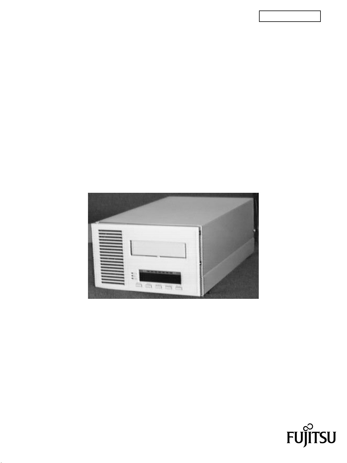
M2488 CARTRIDGE TAPE DRIVE
PRODUCT GUIDE
C144-E019-03EN
Page 2

Please complete the comment from at the back of this manual and send it by mail or facsimile to the
indicated address.
The contents of this manual may be revised without prior notice.
The contents of this manual shall not be disclosed in any way or reproduced in any media without the
express written permission of Fujitsu Limited.
All Rights Reserved, Copyright © FUJITSU LIMITED 1996, 1997
C144-E019-03EN
Page 3

M2488 USER’S GUIDE PREFACE
PREFACE
The M2488 User’s Guide provides the information necessary for the user to operate the M2488 Cartridge Tape Drive.
Chapter 1 Introduction
This chapter provides an overview of the M2488 Cartridge Tape Drive and its optional equipment.
Chapter 2 Installation Instructions
This chapter provides procedures for the preparation and assembly of the M2488 Cartridge Tape
Drive.
Chapter 3 Controls and Indicators
This chapter describes the controls, indicators and connectors for the M2488 Cartridge Tape Drive
and its optional equipment.
Chapter 4 Configuration
This chapter describes the configuration menus of the M2488 Cartridge Tape Drive.
Chapter 5 Operating Instructions
This chapter provides procedures for operating the M2488 Cartridge Tape Drive and its optional
equipment.
Chapter 6 Maintenance and Servicing
This chapter describes the user maintenance and servicing of the M2488 Cartridge Tape Drive.
Chapter 7 Parts List
This chapter describes the M2488 models and optional equipment available.
The ANSI X3.131-199x SCSI specification may be purchased from:
American National Standard Institute, Inc.
1430 Broadway, New York, N.Y. 10018
Tel. (212) 642-4900
SCSI-2 unreleased documentation X3B5/87-099 may be obtained from:
Global Engineering Documents
2805 McGaw
Irvine, CA 92714
CONVENTION
Hexadecimal numbers are denoted by an “h” following the number (e.g. 23h) or 0xNN.
Binary numbers are denoted by a “b” following the number (e.g. 001b).
C144-E019-03EN i
Page 4

Page 5

M2488 PRODUCT GUIDE TABLE OF CONTENTS
TABLE OF CONTENTS
CHAPTER TITLE PAGE
REVISION RECORD. . . . . . . . . . . . . . . . . . . . . . . . . . . . . . . . . . . . . . . . . . . . . . . . . . . . . . . . i
DIRECTORY. . . . . . . . . . . . . . . . . . . . . . . . . . . . . . . . . . . . . . . . . . . . . . . . . . . . . . . . . . . . . . . ii
AGENCY STATEMENTS . . . . . . . . . . . . . . . . . . . . . . . . . . . . . . . . . . . . . . . . . . . . . . . . . . . . iii
PREFACE . . . . . . . . . . . . . . . . . . . . . . . . . . . . . . . . . . . . . . . . . . . . . . . . . . . . . . . . . . . . . . . . . iv
INFORMATION LOCATOR . . . . . . . . . . . . . . . . . . . . . . . . . . . . . . . . . . . . . . . . . . . . . . . . . vi
TABLE OF CONTENTS . . . . . . . . . . . . . . . . . . . . . . . . . . . . . . . . . . . . . . . . . . . . . . . . . . . . . ix
LIST OF FIGURES. . . . . . . . . . . . . . . . . . . . . . . . . . . . . . . . . . . . . . . . . . . . . . . . . . . . . . . . . . xxi
LIST OF TABLES. . . . . . . . . . . . . . . . . . . . . . . . . . . . . . . . . . . . . . . . . . . . . . . . . . . . . . . . . . . xxiii
1
INSTALLATION INSTRUCTIONS. . . . . . . . . . . . . . . . . . . . . . . . . . . . . . . . . . . . . . . . . . . . 1-1
1-1 INTRODUCTION . . . . . . . . . . . . . . . . . . . . . . . . . . . . . . . . . . . . . . . . . . . . . . . . . . . . 1-1
1-2 PREPARING THE M2488 AND ITS OPTIONAL EQUIPMENT . . . . . . . . . . . . . . 1-1
1-3 CONFIGURATIONS. . . . . . . . . . . . . . . . . . . . . . . . . . . . . . . . . . . . . . . . . . . . . . . . . . 1-1
1-3.1 Rack-mount . . . . . . . . . . . . . . . . . . . . . . . . . . . . . . . . . . . . . . . . . . . . . . . . . . . 1-2
1-3.2 Desktop. . . . . . . . . . . . . . . . . . . . . . . . . . . . . . . . . . . . . . . . . . . . . . . . . . . . . . . 1-3
1-4 UNPACKING INSTRUCTIONS . . . . . . . . . . . . . . . . . . . . . . . . . . . . . . . . . . . . . . . . 1-4
1-4.1 Unpack the M2488 Tape Drive . . . . . . . . . . . . . . . . . . . . . . . . . . . . . . . . . . . . 1-4
1-4.2 Unpack the Automatic Cartridge Loader . . . . . . . . . . . . . . . . . . . . . . . . . . . . . 1-5
1-4.3 Unpack the Flush-mounted Automatic Cartridge Loader . . . . . . . . . . . . . . . . 1-6
1-5 EQUIPMENT INSPECTION . . . . . . . . . . . . . . . . . . . . . . . . . . . . . . . . . . . . . . . . . . . 1-7
1-5.1 Inspect the M2488 Tape Drive. . . . . . . . . . . . . . . . . . . . . . . . . . . . . . . . . . . . . 1-7
1-5.2 Inspect the ACL . . . . . . . . . . . . . . . . . . . . . . . . . . . . . . . . . . . . . . . . . . . . . . . . 1-7
1-5.3 Inspect the FACL . . . . . . . . . . . . . . . . . . . . . . . . . . . . . . . . . . . . . . . . . . . . . . . 1-7
1-6 ASSEMBLY INSTRUCTIONS. . . . . . . . . . . . . . . . . . . . . . . . . . . . . . . . . . . . . . . . . . 1-8
1-6.1 General Installation and Assembly Instructions. . . . . . . . . . . . . . . . . . . . . . . . 1-9
1-6.1.1 Air Flow and Service Clearances. . . . . . . . . . . . . . . . . . . . . . . . . . . 1-9
1-6.2 Interface Personality Module Installation . . . . . . . . . . . . . . . . . . . . . . . . . . . . 1-9
1-6.3 Cable and Power Connections . . . . . . . . . . . . . . . . . . . . . . . . . . . . . . . . . . . . . 1-10
1-6.4 Desktop Installation Instructions . . . . . . . . . . . . . . . . . . . . . . . . . . . . . . . . . . . 1-11
1-6.4.1 Tools Required. . . . . . . . . . . . . . . . . . . . . . . . . . . . . . . . . . . . . . . . . 1-11
1-6.4.2 Tape Drive Only. . . . . . . . . . . . . . . . . . . . . . . . . . . . . . . . . . . . . . . . 1-11
1-6.4.3 Drive with ACL Attached (5-Cartridge Magazine) . . . . . . . . . . . . . 1-11
1-6.4.4 Drive with ACL Attached (10-Cartridge Magazine) . . . . . . . . . . . . 1-12
1-6.4.5 Drive with FACL Attached . . . . . . . . . . . . . . . . . . . . . . . . . . . . . . . 1-15
1-6.5 Rack-Mount Installation. . . . . . . . . . . . . . . . . . . . . . . . . . . . . . . . . . . . . . . . . . 1-19
1-6.5.1 Tools Required. . . . . . . . . . . . . . . . . . . . . . . . . . . . . . . . . . . . . . . . . 1-19
1-6.5.2 Adjust the Guide Plate . . . . . . . . . . . . . . . . . . . . . . . . . . . . . . . . . . . 1-19
1-6.5.2.1 Inner Cover Mounted to Mounting Tray. . . . . . . . . . . . 1-19
1-6.5.2.2 Inner Cover NOT Mounted to Mounting Tray . . . . . . . 1-19
1-6.5.3 Screw Plate Mounting . . . . . . . . . . . . . . . . . . . . . . . . . . . . . . . . . . . 1-20
C144-E019-03EN iii
Page 6

TABLE OF CONTENTS M2488 PRODUCT GUIDE
TABLE OF CONTENTS - CONTINUED
CHAPTER TITLE PAGE
1-6.5.4 Attach Mounting Tray. . . . . . . . . . . . . . . . . . . . . . . . . . . . . . . . . . . .1-20
1-6.5.5 Adjust the Brackets . . . . . . . . . . . . . . . . . . . . . . . . . . . . . . . . . . . . . .1-22
1-6.5.6 Install the M2488 or M2488 with Medium Changer on the
Mounting Tray . . . . . . . . . . . . . . . . . . . . . . . . . . . . . . . . . . . . . . . . . . . . . . . . .1-23
1-6.6 Installation of the Automatic Cartridge Loader. . . . . . . . . . . . . . . . . . . . . . . . .1-26
1-6.6.1 Prepare the M2488 Tape Drive . . . . . . . . . . . . . . . . . . . . . . . . . . . . .1-27
1-6.6.2 Prepare the ACL . . . . . . . . . . . . . . . . . . . . . . . . . . . . . . . . . . . . . . . .1-28
1-6.6.3 Connect the M2488 and the ACL . . . . . . . . . . . . . . . . . . . . . . . . . . .1-29
1-6.7 Installation of the Flush-mount Automatic Cartridge Loader. . . . . . . . . . . . . .1-32
1-6.7.1 Prepare the M2488 Tape Drive . . . . . . . . . . . . . . . . . . . . . . . . . . . . .1-33
1-6.7.2 Prepare the FACL . . . . . . . . . . . . . . . . . . . . . . . . . . . . . . . . . . . . . . .1-34
1-6.7.3 Connect the M2488 and the FACL . . . . . . . . . . . . . . . . . . . . . . . . . .1-35
1-7 PREPARATION FOR USE . . . . . . . . . . . . . . . . . . . . . . . . . . . . . . . . . . . . . . . . . . . . .1-37
2
DESIGN ARCHITECTURE . . . . . . . . . . . . . . . . . . . . . . . . . . . . . . . . . . . . . . . . . . . . . . . . . . .2-1
2-1 INTRODUCTION. . . . . . . . . . . . . . . . . . . . . . . . . . . . . . . . . . . . . . . . . . . . . . . . . . . . .2-1
2-2 OPERATION OF THE M2488. . . . . . . . . . . . . . . . . . . . . . . . . . . . . . . . . . . . . . . . . . .2-1
2-3 OPERATION OF THE MAGNETIC TAPE CONTROLLER (MTC). . . . . . . . . . . . .2-2
2-3.1 Data Path . . . . . . . . . . . . . . . . . . . . . . . . . . . . . . . . . . . . . . . . . . . . . . . . . . . . . .2-2
2-3.2 Data Buffer . . . . . . . . . . . . . . . . . . . . . . . . . . . . . . . . . . . . . . . . . . . . . . . . . . . .2-2
2-3.3 ERDC Compression Feature . . . . . . . . . . . . . . . . . . . . . . . . . . . . . . . . . . . . . . .2-2
2-3.4 Microprocessor Control. . . . . . . . . . . . . . . . . . . . . . . . . . . . . . . . . . . . . . . . . . .2-3
2-3.5 Firmware . . . . . . . . . . . . . . . . . . . . . . . . . . . . . . . . . . . . . . . . . . . . . . . . . . . . . .2-4
2-4 OPERATION OF THE MAGNETIC TAPE UNIT (MTU) . . . . . . . . . . . . . . . . . . . . .2-4
2-4.1 Airless Tape Path. . . . . . . . . . . . . . . . . . . . . . . . . . . . . . . . . . . . . . . . . . . . . . . .2-4
2-4.2 Read and Write Electronics. . . . . . . . . . . . . . . . . . . . . . . . . . . . . . . . . . . . . . . .2-5
3
SCSI MESSAGES. . . . . . . . . . . . . . . . . . . . . . . . . . . . . . . . . . . . . . . . . . . . . . . . . . . . . . . . . . . .3-1
3-1 INTRODUCTION. . . . . . . . . . . . . . . . . . . . . . . . . . . . . . . . . . . . . . . . . . . . . . . . . . . . .3-1
3-2 M2488 TAPE AND MEDIUM CHANGER SCSI MESSAGES. . . . . . . . . . . . . . . . .3-1
3-2.1 ABORT code 06h . . . . . . . . . . . . . . . . . . . . . . . . . . . . . . . . . . . . . . . . . . . . . . .3-2
3-2.2 BUS DEVICE RESET code 0Ch . . . . . . . . . . . . . . . . . . . . . . . . . . . . . . . . . . .3-2
3-2.3 COMMAND COMPLETE code 00h . . . . . . . . . . . . . . . . . . . . . . . . . . . . . . . .3-2
3-2.4 DISCONNECT code 04h . . . . . . . . . . . . . . . . . . . . . . . . . . . . . . . . . . . . . . . . .3-2
3-2.5 EXTENDED MESSAGE FORMAT code 01h. . . . . . . . . . . . . . . . . . . . . . . . .3-3
3-2.5.1 Synchronous Data Transfer Request (SDTR) . . . . . . . . . . . . . . . . . .3-3
3-2.5.2 Wide Data Transfer Request (WDTR) . . . . . . . . . . . . . . . . . . . . . . .3-5
3-2.6 IDENTIFY code 80h-FFh . . . . . . . . . . . . . . . . . . . . . . . . . . . . . . . . . . . . . . . . .3-7
3-2.7 IGNORE WIDE RESIDUE code 23h . . . . . . . . . . . . . . . . . . . . . . . . . . . . . . . .3-7
3-2.8 INITIATOR DETECTED ERROR code 05h . . . . . . . . . . . . . . . . . . . . . . . . . .3-8
3-2.9 LINKED COMMAND COMPLETE code 0Ah . . . . . . . . . . . . . . . . . . . . . . . .3-8
iv C144-E019-03EN
Page 7

M2488 PRODUCT GUIDE TABLE OF CONTENTS
TABLE OF CONTENTS - CONTINUED
CHAPTER TITLE PAGE
3-2.10 LINKED COMMAND COMPLETE (WITH FLAG) code 0Bh. . . . . . . . . . 3-8
3-2.11 MESSAGE PARITY ERROR code 09h . . . . . . . . . . . . . . . . . . . . . . . . . . . . 3-8
3-2.12 MESSAGE REJECT code 07h. . . . . . . . . . . . . . . . . . . . . . . . . . . . . . . . . . . . 3-8
3-2.13 NO OPERATION code 08h. . . . . . . . . . . . . . . . . . . . . . . . . . . . . . . . . . . . . . 3-9
3-2.14 RESTORE POINTERS code 03h. . . . . . . . . . . . . . . . . . . . . . . . . . . . . . . . . . 3-9
3-2.15 SAVE DATA POINTER code 02h . . . . . . . . . . . . . . . . . . . . . . . . . . . . . . . . 3-9
3-3 SCSI BUS STATUS . . . . . . . . . . . . . . . . . . . . . . . . . . . . . . . . . . . . . . . . . . . . . . . . . . 3-10
3-3.1 Good Status . . . . . . . . . . . . . . . . . . . . . . . . . . . . . . . . . . . . . . . . . . . . . . . . . . . 3-10
3-3.2 Check Condition. . . . . . . . . . . . . . . . . . . . . . . . . . . . . . . . . . . . . . . . . . . . . . . . 3-10
3-3.3 Busy Status. . . . . . . . . . . . . . . . . . . . . . . . . . . . . . . . . . . . . . . . . . . . . . . . . . . . 3-10
3-3.4 Intermediate Status. . . . . . . . . . . . . . . . . . . . . . . . . . . . . . . . . . . . . . . . . . . . . . 3-10
3-3.5 Reservation Conflict Status . . . . . . . . . . . . . . . . . . . . . . . . . . . . . . . . . . . . . . . 3-11
4
TAPE UNIT SCSI COMMANDS . . . . . . . . . . . . . . . . . . . . . . . . . . . . . . . . . . . . . . . . . . . . . . 4-1
4-1 INTRODUCTION . . . . . . . . . . . . . . . . . . . . . . . . . . . . . . . . . . . . . . . . . . . . . . . . . . . . 4-1
4-2 LOGICAL UNITS AND SCSI IDS. . . . . . . . . . . . . . . . . . . . . . . . . . . . . . . . . . . . . . . 4-1
4-2.1 Target ID . . . . . . . . . . . . . . . . . . . . . . . . . . . . . . . . . . . . . . . . . . . . . . . . . . . . . 4-1
4-2.2 Initiator ID . . . . . . . . . . . . . . . . . . . . . . . . . . . . . . . . . . . . . . . . . . . . . . . . . . . . 4-1
4-2.3 Tape LUN 0 . . . . . . . . . . . . . . . . . . . . . . . . . . . . . . . . . . . . . . . . . . . . . . . . . . . 4-1
4-2.4 Media Changer LUN 4. . . . . . . . . . . . . . . . . . . . . . . . . . . . . . . . . . . . . . . . . . . 4-1
4-2.5 LUN . . . . . . . . . . . . . . . . . . . . . . . . . . . . . . . . . . . . . . . . . . . . . . . . . . . . . . . . . 4-1
4-3 M2488 TAPE SCSI COMMANDS. . . . . . . . . . . . . . . . . . . . . . . . . . . . . . . . . . . . . . . 4-2
4-3.1 Command Description Block Format. . . . . . . . . . . . . . . . . . . . . . . . . . . . . . . . 4-4
4-3.2 CHANGE DEFINITION command 40h . . . . . . . . . . . . . . . . . . . . . . . . . . . . . 4-5
4-3.2.1 CHANGE DEFINITION CDB Description. . . . . . . . . . . . . . . . . . . 4-5
4-3.2.2 CHANGE DEFINITION Changes. . . . . . . . . . . . . . . . . . . . . . . . . . 4-6
4-3.2.3 CHANGE DEFINITION CHECK CONDITION Status . . . . . . . . . 4-7
4-3.2.4 CHANGE DEFINITION Sense Keys . . . . . . . . . . . . . . . . . . . . . . . 4-7
4-3.3 DISPLAY command CFh (11h). . . . . . . . . . . . . . . . . . . . . . . . . . . . . . . . . . . . 4-8
4-3.3.1 DISPLAY CDB Description (11h). . . . . . . . . . . . . . . . . . . . . . . . . . 4-8
4-3.3.2 Display Data (11h) . . . . . . . . . . . . . . . . . . . . . . . . . . . . . . . . . . . . . . 4-9
4-3.3.3 DISPLAY Sense Keys (11h) . . . . . . . . . . . . . . . . . . . . . . . . . . . . . . 4-11
4-3.4 DISPLAY command CFh (10h). . . . . . . . . . . . . . . . . . . . . . . . . . . . . . . . . . . . 4-12
4-3.4.1 DISPLAY CDB Description (10h). . . . . . . . . . . . . . . . . . . . . . . . . . 4-12
4-3.4.2 Display Data (10h) . . . . . . . . . . . . . . . . . . . . . . . . . . . . . . . . . . . . . . 4-13
4-3.4.3 DISPLAY Sense Keys (10h) . . . . . . . . . . . . . . . . . . . . . . . . . . . . . . 4-14
4-3.5 ERASE command 19h . . . . . . . . . . . . . . . . . . . . . . . . . . . . . . . . . . . . . . . . . . . 4-15
4-3.5.1 ERASE CDB Description. . . . . . . . . . . . . . . . . . . . . . . . . . . . . . . . . 4-15
4-3.5.2 ERASE Sense Keys . . . . . . . . . . . . . . . . . . . . . . . . . . . . . . . . . . . . . 4-16
4-3.6 INQUIRY command 12h . . . . . . . . . . . . . . . . . . . . . . . . . . . . . . . . . . . . . . . . . 4-18
4-3.6.1 INQUIRY CDB Description . . . . . . . . . . . . . . . . . . . . . . . . . . . . . . 4-18
4-3.6.2 INQUIRY CHECK CONDITION Status. . . . . . . . . . . . . . . . . . . . . 4-19
C144-E019-03EN v
Page 8

TABLE OF CONTENTS M2488 PRODUCT GUIDE
TABLE OF CONTENTS - CONTINUED
CHAPTER TITLE PAGE
4-3.6.3 Inquiry Data. . . . . . . . . . . . . . . . . . . . . . . . . . . . . . . . . . . . . . . . . . . .4-19
4-3.6.4 INQUIRY Sense Keys. . . . . . . . . . . . . . . . . . . . . . . . . . . . . . . . . . . .4-24
4-3.7 LOAD UNLOAD command 1Bh . . . . . . . . . . . . . . . . . . . . . . . . . . . . . . . . . . .4-25
4-3.7.1 LOAD UNLOAD CDB Description . . . . . . . . . . . . . . . . . . . . . . . . .4-25
4-3.7.2 LOAD UNLOAD CHECK CONDITION Status . . . . . . . . . . . . . . .4-26
4-3.7.3 LOAD UNLOAD Sense Keys. . . . . . . . . . . . . . . . . . . . . . . . . . . . . .4-27
4-3.8 LOCATE command 2Bh. . . . . . . . . . . . . . . . . . . . . . . . . . . . . . . . . . . . . . . . . .4-28
4-3.8.1 LOCATE CDB Description. . . . . . . . . . . . . . . . . . . . . . . . . . . . . . . .4-28
4-3.8.2 LOCATE CHECK CONDITION Status. . . . . . . . . . . . . . . . . . . . . .4-31
4-3.8.3 LOCATE Sense Keys . . . . . . . . . . . . . . . . . . . . . . . . . . . . . . . . . . . .4-31
4-3.9 LOG SELECT command 4Ch. . . . . . . . . . . . . . . . . . . . . . . . . . . . . . . . . . . . . .4-32
4-3.9.1 LOG SELECT CDB Description. . . . . . . . . . . . . . . . . . . . . . . . . . . .4-32
4-3.9.2 LOG SELECT CHECK CONDITION Status. . . . . . . . . . . . . . . . . .4-32
4-3.10 LOG SENSE command 4Dh. . . . . . . . . . . . . . . . . . . . . . . . . . . . . . . . . . . . . .4-33
4-3.10.1 LOG SENSE CDB Description. . . . . . . . . . . . . . . . . . . . . . . . . . . .4-33
4-3.10.2 LOG SENSE Operation. . . . . . . . . . . . . . . . . . . . . . . . . . . . . . . . . .4-34
4-3.10.3 LOG SENSE Parameters. . . . . . . . . . . . . . . . . . . . . . . . . . . . . . . . .4-35
4-3.10.3.1 Log Sense Pages . . . . . . . . . . . . . . . . . . . . . . . . . . . . . .4-37
4-3.10.4 LOG SENSE Sense Keys . . . . . . . . . . . . . . . . . . . . . . . . . . . . . . . .4-48
4-3.11 LOOP WRITE TO READ command C1h. . . . . . . . . . . . . . . . . . . . . . . . . . . .4-49
4-3.11.1 LOOP WRITE TO READ CDB Description . . . . . . . . . . . . . . . . .4-49
4-3.11.2 LOOP WRITE TO READ CHECK CONDITION Status . . . . . . .4-50
4-3.11.3 LOOP WRITE TO READ Sense Keys . . . . . . . . . . . . . . . . . . . . . .4-50
4-3.12 MODE SELECT command 15h . . . . . . . . . . . . . . . . . . . . . . . . . . . . . . . . . . .4-51
4-3.12.1 MODE SELECT CDB Description. . . . . . . . . . . . . . . . . . . . . . . . .4-51
4-3.12.2 Mode Select Data. . . . . . . . . . . . . . . . . . . . . . . . . . . . . . . . . . . . . . .4-52
4-3.12.3 MODE SELECT Sense Keys . . . . . . . . . . . . . . . . . . . . . . . . . . . . .4-55
4-3.13 MODE SENSE command 1Ah . . . . . . . . . . . . . . . . . . . . . . . . . . . . . . . . . . . .4-56
4-3.13.1 MODE SENSE CDB Description . . . . . . . . . . . . . . . . . . . . . . . . . .4-56
4-3.13.2 Mode Sense Data. . . . . . . . . . . . . . . . . . . . . . . . . . . . . . . . . . . . . . .4-57
4-3.13.3 Mode Settings . . . . . . . . . . . . . . . . . . . . . . . . . . . . . . . . . . . . . . . . .4-60
4-3.13.4 Initiator Setup . . . . . . . . . . . . . . . . . . . . . . . . . . . . . . . . . . . . . . . . .4-60
4-3.13.5 MODE SENSE Sense Keys. . . . . . . . . . . . . . . . . . . . . . . . . . . . . . .4-62
4-3.14 READ command 08h. . . . . . . . . . . . . . . . . . . . . . . . . . . . . . . . . . . . . . . . . . . .4-63
4-3.14.1 READ CDB Description . . . . . . . . . . . . . . . . . . . . . . . . . . . . . . . . .4-63
4-3.14.2 READ CHECK CONDITION Status . . . . . . . . . . . . . . . . . . . . . . .4-64
4-3.14.3 READ Sense Keys. . . . . . . . . . . . . . . . . . . . . . . . . . . . . . . . . . . . . .4-66
4-3.15 READ BLOCK LIMITS command 05h . . . . . . . . . . . . . . . . . . . . . . . . . . . . .4-68
4-3.15.1 READ BLOCK LIMITS CDB Description. . . . . . . . . . . . . . . . . . .4-68
4-3.15.2 READ BLOCK LIMITS Sense Keys . . . . . . . . . . . . . . . . . . . . . . .4-69
4-3.16 READ BUFFER command 3Ch . . . . . . . . . . . . . . . . . . . . . . . . . . . . . . . . . . .4-70
4-3.16.1 READ BUFFER CDB Description . . . . . . . . . . . . . . . . . . . . . . . . .4-70
vi C144-E019-03EN
Page 9

M2488 PRODUCT GUIDE TABLE OF CONTENTS
TABLE OF CONTENTS - CONTINUED
CHAPTER TITLE PAGE
4-3.16.2 READ BUFFER Sense Keys . . . . . . . . . . . . . . . . . . . . . . . . . . . . . 4-74
4-3.17 READ POSITION command 34h . . . . . . . . . . . . . . . . . . . . . . . . . . . . . . . . . 4-75
4-3.17.1 READ POSITION CDB Description. . . . . . . . . . . . . . . . . . . . . . . 4-75
4-3.17.2 READ POSITION Return Data . . . . . . . . . . . . . . . . . . . . . . . . . . . 4-76
4-3.17.3 Description of Block ID Format. . . . . . . . . . . . . . . . . . . . . . . . . . . 4-78
4-3.17.4 READ POSITION Sense Keys . . . . . . . . . . . . . . . . . . . . . . . . . . . 4-79
4-3.18 READ REVERSE command 0Fh . . . . . . . . . . . . . . . . . . . . . . . . . . . . . . . . . 4-80
4-3.18.1 READ REVERSE CDB Description . . . . . . . . . . . . . . . . . . . . . . . 4-80
4-3.18.2 READ REVERSE CHECK CONDITION Status . . . . . . . . . . . . . 4-81
4-3.18.3 READ REVERSE Sense Keys. . . . . . . . . . . . . . . . . . . . . . . . . . . . 4-82
4-3.19 RECEIVE DIAGNOSTIC RESULTS command 1Ch. . . . . . . . . . . . . . . . . . 4-83
4-3.19.1 RECEIVE DIAGNOSTIC RESULTS CDB Description. . . . . . . . 4-83
4-3.19.2 Diagnostic Page Codes (PF=1 in SEND DIAGNOSTIC
command CDB) . . . . . . . . . . . . . . . . . . . . . . . . . . . . . . . . . . . . . . . . . . . . . . . 4-85
4-3.19.3 Diagnostic Parameter List (PF=0 in SEND DIAGNOSTIC
command CDB) . . . . . . . . . . . . . . . . . . . . . . . . . . . . . . . . . . . . . . . . . . . . . . . 4-87
4-3.19.4 RECEIVE DIAGNOSTIC RESULTS CHECK CONDITION
Status. . . . . . . . . . . . . . . . . . . . . . . . . . . . . . . . . . . . . . . . . . . . . . . . . . . . . . . . 4-87
4-3.19.5 RECEIVE DIAGNOSTIC RESULTS Sense Keys . . . . . . . . . . . . 4-88
4-3.20 RECEIVE DIAGNOSTIC RESULTS (FACTORY MODE) command 1Ch 4-89
4-3.20.1 RECEIVE DIAGNOSTIC RESULTS (FACTORY MODE)
CDB Description. . . . . . . . . . . . . . . . . . . . . . . . . . . . . . . . . . . . . . . . . . . . . . . 4-89
4-3.20.2 Diagnostic Page Codes (PF=1 in SEND DIAGNOSTIC
command CDB) . . . . . . . . . . . . . . . . . . . . . . . . . . . . . . . . . . . . . . . . . . . . . . . 4-91
4-3.20.3 Diagnostic Parameter List (PF=0 in SEND DIAGNOSTIC
command CDB) . . . . . . . . . . . . . . . . . . . . . . . . . . . . . . . . . . . . . . . . . . . . . . . 4-96
4-3.20.4 RECEIVE DIAGNOSTIC RESULTS CHECK CONDITION
Status. . . . . . . . . . . . . . . . . . . . . . . . . . . . . . . . . . . . . . . . . . . . . . . . . . . . . . . . 4-96
4-3.20.5 RECEIVE DIAGNOSTIC RESULTS Sense Keys . . . . . . . . . . . . 4-97
4-3.21 RECOVER BUFFERED DATA command 14h . . . . . . . . . . . . . . . . . . . . . . 4-98
4-3.21.1 RECOVER BUFFERED DATA CDB Description. . . . . . . . . . . . 4-98
4-3.21.2 RECOVER BUFFERED DATA Operation. . . . . . . . . . . . . . . . . . 4-99
4-3.21.3 RECOVER BUFFERED DATA CHECK CONDITION Status . . 4-99
4-3.21.4 RECOVER BUFFERED DATA Sense Keys . . . . . . . . . . . . . . . . 4-100
4-3.22 RELEASE UNIT command 17h . . . . . . . . . . . . . . . . . . . . . . . . . . . . . . . . . . 4-101
4-3.22.1 RELEASE UNIT CDB Description. . . . . . . . . . . . . . . . . . . . . . . . 4-101
4-3.22.2 RELEASE UNIT Operation. . . . . . . . . . . . . . . . . . . . . . . . . . . . . . 4-102
4-3.22.3 RELEASE UNIT Sense Keys . . . . . . . . . . . . . . . . . . . . . . . . . . . . 4-102
4-3.23 REQUEST SENSE command 03h. . . . . . . . . . . . . . . . . . . . . . . . . . . . . . . . . 4-103
4-3.23.1 REQUEST SENSE CDB Description . . . . . . . . . . . . . . . . . . . . . . 4-103
4-3.23.2 REQUEST SENSE CHECK CONDITION Status . . . . . . . . . . . . 4-103
4-3.23.3 REQUEST SENSE Sense Keys . . . . . . . . . . . . . . . . . . . . . . . . . . . 4-104
4-3.24 Report Density Support command 44h . . . . . . . . . . . . . . . . . . . . . . . . . . . . . 4-105
C144-E019-03EN vii
Page 10

TABLE OF CONTENTS M2488 PRODUCT GUIDE
TABLE OF CONTENTS - CONTINUED
CHAPTER TITLE PAGE
4-3.24.1 REPORT DENSITY SUPPORT CDB Description . . . . . . . . . . . .4-105
4-3.24.2 REPORT DENSITY SUPPORT Data. . . . . . . . . . . . . . . . . . . . . . .4-106
4-3.24.3 REPORT DENSITY SUPPORT Sense Keys . . . . . . . . . . . . . . . . .4-111
4-3.25 RESERVE UNIT command 16h. . . . . . . . . . . . . . . . . . . . . . . . . . . . . . . . . . .4-112
4-3.25.1 RESERVE UNIT CDB Description . . . . . . . . . . . . . . . . . . . . . . . .4-112
4-3.25.2 RESERVE UNIT Operation . . . . . . . . . . . . . . . . . . . . . . . . . . . . . .4-113
4-3.25.3 RESERVE UNIT Sense Keys . . . . . . . . . . . . . . . . . . . . . . . . . . . . .4-114
4-3.26 REWIND command 01h . . . . . . . . . . . . . . . . . . . . . . . . . . . . . . . . . . . . . . . . .4-115
4-3.26.1 REWIND CDB Description . . . . . . . . . . . . . . . . . . . . . . . . . . . . . .4-115
4-3.26.2 REWIND CHECK CONDITION Status. . . . . . . . . . . . . . . . . . . . .4-115
4-3.26.3 REWIND Sense Keys . . . . . . . . . . . . . . . . . . . . . . . . . . . . . . . . . . .4-116
4-3.27 SEND DIAGNOSTIC command 1Dh. . . . . . . . . . . . . . . . . . . . . . . . . . . . . . .4-117
4-3.27.1 SEND DIAGNOSTIC CDB Description. . . . . . . . . . . . . . . . . . . . .4-117
4-3.27.2 SEND DIAGNOSTIC CHECK CONDITION Status. . . . . . . . . . .4-119
4-3.27.3 Diagnostic Pages (PF=1) . . . . . . . . . . . . . . . . . . . . . . . . . . . . . . . . .4-119
4-3.27.4 Diagnostic Parameter List (PF=0). . . . . . . . . . . . . . . . . . . . . . . . . .4-122
4-3.27.5 SEND DIAGNOSTIC Sense Keys . . . . . . . . . . . . . . . . . . . . . . . . .4-123
4-3.28 SEND DIAGNOSTIC (FACTORY MODE) command 1Dh . . . . . . . . . . . . .4-124
4-3.28.1 SEND DIAGNOSTIC CDB Description. . . . . . . . . . . . . . . . . . . . .4-124
4-3.28.2 SEND DIAGNOSTIC (FACTORY MODE) CHECK
CONDITION Status. . . . . . . . . . . . . . . . . . . . . . . . . . . . . . . . . . . . . . . . . . . . .4-126
4-3.28.3 Diagnostic Pages (PF=1). . . . . . . . . . . . . . . . . . . . . . . . . . . . . . . . .4-126
4-3.28.4 Diagnostic Parameter List (PF=0). . . . . . . . . . . . . . . . . . . . . . . . . .4-132
4-3.28.5 SEND DIAGNOSTIC Sense Keys . . . . . . . . . . . . . . . . . . . . . . . . .4-134
4-3.29 SPACE command 11h. . . . . . . . . . . . . . . . . . . . . . . . . . . . . . . . . . . . . . . . . . .4-135
4-3.29.1 SPACE CDB Description . . . . . . . . . . . . . . . . . . . . . . . . . . . . . . . .4-135
4-3.29.2 SPACE CHECK CONDITION Status . . . . . . . . . . . . . . . . . . . . . .4-136
4-3.29.3 SPACE Sense Keys. . . . . . . . . . . . . . . . . . . . . . . . . . . . . . . . . . . . .4-137
4-3.30 TEST UNIT READY command 00h. . . . . . . . . . . . . . . . . . . . . . . . . . . . . . . .4-138
4-3.30.1 TEST UNIT READY CDB Description . . . . . . . . . . . . . . . . . . . . .4-138
4-3.30.2 TEST UNIT READY CHECK CONDITION Status . . . . . . . . . . .4-138
4-3.30.3 TEST UNIT READY Sense Keys. . . . . . . . . . . . . . . . . . . . . . . . . .4-139
4-3.31 WRITE command 0Ah . . . . . . . . . . . . . . . . . . . . . . . . . . . . . . . . . . . . . . . . . .4-140
4-3.31.1 WRITE CDB Description . . . . . . . . . . . . . . . . . . . . . . . . . . . . . . . .4-140
4-3.31.2 WRITE CHECK CONDITION Status . . . . . . . . . . . . . . . . . . . . . .4-140
4-3.31.3 WRITE Sense Keys. . . . . . . . . . . . . . . . . . . . . . . . . . . . . . . . . . . . .4-143
4-3.32 WRITE BUFFER command 3Bh . . . . . . . . . . . . . . . . . . . . . . . . . . . . . . . . . .4-144
4-3.32.1 WRITE BUFFER CDB Description . . . . . . . . . . . . . . . . . . . . . . . .4-144
4-3.32.2 WRITE BUFFER CHECK CONDITION Status . . . . . . . . . . . . . .4-148
4-3.32.3 WRITE BUFFER Sense Keys. . . . . . . . . . . . . . . . . . . . . . . . . . . . .4-149
4-3.33 WRITE FILEMARKS command 10h. . . . . . . . . . . . . . . . . . . . . . . . . . . . . . .4-150
4-3.33.1 WRITE FILEMARKS CDB Description . . . . . . . . . . . . . . . . . . . .4-150
viii C144-E019-03EN
Page 11

M2488 PRODUCT GUIDE TABLE OF CONTENTS
TABLE OF CONTENTS - CONTINUED
CHAPTER TITLE PAGE
4-3.33.2 WRITE FILEMARKS CHECK CONDITION Status. . . . . . . . . . 4-151
4-3.33.3 WRITE FILEMARKS Sense Keys . . . . . . . . . . . . . . . . . . . . . . . . 4-152
4-4 COMMAND DISCONNECTION. . . . . . . . . . . . . . . . . . . . . . . . . . . . . . . . . . . . . . . . 4-153
4-5 SCSI RESET . . . . . . . . . . . . . . . . . . . . . . . . . . . . . . . . . . . . . . . . . . . . . . . . . . . . . . . . 4-153
5
TAPE UNIT PARAMETERS. . . . . . . . . . . . . . . . . . . . . . . . . . . . . . . . . . . . . . . . . . . . . . . . . . 5-1
5-1 INTRODUCTION . . . . . . . . . . . . . . . . . . . . . . . . . . . . . . . . . . . . . . . . . . . . . . . . . . . . 5-1
5-2 ADDITIONAL COMMAND INFORMATION ON MTU MODE SELECT AND
MODE SENSE COMMANDS. . . . . . . . . . . . . . . . . . . . . . . . . . . . . . . . . . . . . . . . . . . . . . . 5-1
5-2.1 The Parameters Savable Bit (All pages). . . . . . . . . . . . . . . . . . . . . . . . . . . . . . 5-1
5-2.2 Vendor Unique Parameter . . . . . . . . . . . . . . . . . . . . . . . . . . . . . . . . . . . . . . . . 5-2
5-2.3 Error Recovery and Reporting Parameters. . . . . . . . . . . . . . . . . . . . . . . . . . . . 5-4
5-2.4 Disconnect/Reconnect Control Parameters . . . . . . . . . . . . . . . . . . . . . . . . . . . 5-7
5-2.5 Common Device-Type Control Parameters. . . . . . . . . . . . . . . . . . . . . . . . . . . 5-9
5-2.6 Device Configuration Parameters. . . . . . . . . . . . . . . . . . . . . . . . . . . . . . . . . . . 5-11
5-2.7 Density Code 28h. . . . . . . . . . . . . . . . . . . . . . . . . . . . . . . . . . . . . . . . . . . . . . . 5-14
5-2.7.1 M2488 Operation When Density Code 28h Is Not Configured. . . . 5-15
5-2.7.2 M2488 Operation When Density Code 28h Is Configured . . . . . . . 5-15
5-3 MTU INQUIRY/CHANGE DEFINITION VITAL PRODUCT DATA PAGES. . . . 5-17
5-3.1 General VPD Page Format. . . . . . . . . . . . . . . . . . . . . . . . . . . . . . . . . . . . . . . . 5-17
5-3.2 Supported VPD Pages - Page 00h . . . . . . . . . . . . . . . . . . . . . . . . . . . . . . . . . . 5-19
5-3.3 Unit Serial Number Page - Page 80h . . . . . . . . . . . . . . . . . . . . . . . . . . . . . . . . 5-19
5-3.4 Implemented Operating Definition Page - Page 81h . . . . . . . . . . . . . . . . . . . . 5-20
5-3.5 ASCII Implemented Operating Definition Page - Page 82h . . . . . . . . . . . . . . 5-21
5-3.6 Unit Usage Page - Page C0h . . . . . . . . . . . . . . . . . . . . . . . . . . . . . . . . . . . . . . 5-22
5-3.7 Configuration Page - Page C1h . . . . . . . . . . . . . . . . . . . . . . . . . . . . . . . . . . . . 5-23
5-3.8 Product Identification Page - Page C2h . . . . . . . . . . . . . . . . . . . . . . . . . . . . . . 5-24
6
MEDIA CHANGER SCSI COMMANDS. . . . . . . . . . . . . . . . . . . . . . . . . . . . . . . . . . . . . . . . 6-1
6-1 INTRODUCTION . . . . . . . . . . . . . . . . . . . . . . . . . . . . . . . . . . . . . . . . . . . . . . . . . . . . 6-1
6-2 MEDIA CHANGER COMMANDS . . . . . . . . . . . . . . . . . . . . . . . . . . . . . . . . . . . . . . 6-1
6-2.1 EXCHANGE MEDIUM MC command A6h. . . . . . . . . . . . . . . . . . . . . . . . . . 6-2
6-2.1.1 EXCHANGE MEDIUM CDB Description . . . . . . . . . . . . . . . . . . . 6-2
6-2.1.2 Exchange Medium Examples. . . . . . . . . . . . . . . . . . . . . . . . . . . . . . 6-3
6-2.1.3 EXCHANGE MEDIUM Sense Keys. . . . . . . . . . . . . . . . . . . . . . . . 6-4
6-2.2 MODE SELECT MC command 15h . . . . . . . . . . . . . . . . . . . . . . . . . . . . . . . . 6-6
6-2.2.1 MODE SELECT CDB Description . . . . . . . . . . . . . . . . . . . . . . . . . 6-6
6-2.2.2 MODE SELECT CHECK CONDITION Status . . . . . . . . . . . . . . . 6-8
6-2.2.3 MODE SELECT Data . . . . . . . . . . . . . . . . . . . . . . . . . . . . . . . . . . . 6-8
6-2.2.4 MODE SELECT MC Sense Keys . . . . . . . . . . . . . . . . . . . . . . . . . . 6-10
6-2.3 MODE SENSE MC command 1Ah. . . . . . . . . . . . . . . . . . . . . . . . . . . . . . . . . 6-11
C144-E019-03EN ix
Page 12

TABLE OF CONTENTS M2488 PRODUCT GUIDE
TABLE OF CONTENTS - CONTINUED
CHAPTER TITLE PAGE
6-2.3.1 MODE SENSE CDB Description . . . . . . . . . . . . . . . . . . . . . . . . . . .6-11
6-2.3.2 MODE SENSE Data . . . . . . . . . . . . . . . . . . . . . . . . . . . . . . . . . . . . .6-13
6-2.3.3 MODE SENSE MC Sense Keys . . . . . . . . . . . . . . . . . . . . . . . . . . . .6-14
6-2.4 MOVE MEDIUM MC command A5h . . . . . . . . . . . . . . . . . . . . . . . . . . . . . . .6-16
6-2.4.1 MOVE MEDIUM CDB Description. . . . . . . . . . . . . . . . . . . . . . . . .6-16
6-2.4.2 ACL/FACL Tables of Allowed Moves. . . . . . . . . . . . . . . . . . . . . . .6-17
6-2.4.3 MOVE MEDIUM Sense Keys . . . . . . . . . . . . . . . . . . . . . . . . . . . . .6-18
6-2.5 READ ELEMENT STATUS MC command B8h. . . . . . . . . . . . . . . . . . . . . . .6-19
6-2.5.1 READ ELEMENT STATUS CDB Description . . . . . . . . . . . . . . . .6-19
6-2.5.2 READ ELEMENT STATUS Data . . . . . . . . . . . . . . . . . . . . . . . . . .6-21
6-2.5.2.1 Element Status Data . . . . . . . . . . . . . . . . . . . . . . . . . . . .6-22
6-2.5.2.2 Element Status Page . . . . . . . . . . . . . . . . . . . . . . . . . . . .6-23
6-2.5.2.3 Element Descriptors . . . . . . . . . . . . . . . . . . . . . . . . . . . .6-24
6-2.5.3 Source and Destination Elements . . . . . . . . . . . . . . . . . . . . . . . . . . .6-29
6-2.5.4 READ ELEMENT STATUS Sense Keys. . . . . . . . . . . . . . . . . . . . .6-29
6-2.6 TEST UNIT READY MC command 00h . . . . . . . . . . . . . . . . . . . . . . . . . . . . .6-30
6-2.6.1 TEST UNIT READY CDB Description . . . . . . . . . . . . . . . . . . . . . .6-30
6-2.6.2 TEST UNIT READY CHECK CONDITION Status . . . . . . . . . . . .6-30
6-2.6.3 TEST UNIT READY Sense Keys. . . . . . . . . . . . . . . . . . . . . . . . . . .6-31
6-3 ADDITIONAL COMMAND INFORMATION ON MEDIUM CHANGER
MODE SELECT AND MODE SENSE COMMANDS . . . . . . . . . . . . . . . . . . . . . . . . . . . .6-32
6-3.1 Page Code 00h, Device Unique Parameters . . . . . . . . . . . . . . . . . . . . . . . . . . .6-32
6-3.2 Page Code 1Dh, Element Address Assignments. . . . . . . . . . . . . . . . . . . . . . . .6-35
6-3.3 Page Code 1Eh, Transport Geometry Parameters. . . . . . . . . . . . . . . . . . . . . . .6-37
6-3.4 Page Code 1Fh, Device Capabilities . . . . . . . . . . . . . . . . . . . . . . . . . . . . . . . . .6-38
6-4 MC (MEDIUM CHANGER) INQUIRY/CHANGE DEFINITION
VITAL PRODUCT DATA PAGES . . . . . . . . . . . . . . . . . . . . . . . . . . . . . . . . . . . . . . . . . . .6-41
6-4.1 General VPD Page Format . . . . . . . . . . . . . . . . . . . . . . . . . . . . . . . . . . . . . . . .6-41
6-4.2 Supported VPD Pages - Page 00h . . . . . . . . . . . . . . . . . . . . . . . . . . . . . . . . . . .6-42
6-4.3 Implemented Operating Definition Page 81h . . . . . . . . . . . . . . . . . . . . . . . . . .6-43
6-4.4 ASCII Implemented Operating Definition Page 82h. . . . . . . . . . . . . . . . . . . . .6-44
6-4.5 Product Identification Page C2h . . . . . . . . . . . . . . . . . . . . . . . . . . . . . . . . . . . .6-45
7
TAPE PROCESSING. . . . . . . . . . . . . . . . . . . . . . . . . . . . . . . . . . . . . . . . . . . . . . . . . . . . . . . . .7-1
7-1 INTRODUCTION. . . . . . . . . . . . . . . . . . . . . . . . . . . . . . . . . . . . . . . . . . . . . . . . . . . . .7-1
7-2 CHANGING MODE PARAMETERS. . . . . . . . . . . . . . . . . . . . . . . . . . . . . . . . . . . . .7-1
7-2.1 Initiator Setup . . . . . . . . . . . . . . . . . . . . . . . . . . . . . . . . . . . . . . . . . . . . . . . . . .7-1
7-3 PERMANENT ERROR HANDLING . . . . . . . . . . . . . . . . . . . . . . . . . . . . . . . . . . . . .7-3
7-3.1 PERMANENT WRITE ERROR. . . . . . . . . . . . . . . . . . . . . . . . . . . . . . . . . . . .7-3
7-3.2 PERMANENT READ ERROR. . . . . . . . . . . . . . . . . . . . . . . . . . . . . . . . . . . . .7-3
x C144-E019-03EN
Page 13

M2488 PRODUCT GUIDE TABLE OF CONTENTS
TABLE OF CONTENTS - CONTINUED
CHAPTER TITLE PAGE
8
MAINTENANCE AND SERVICING . . . . . . . . . . . . . . . . . . . . . . . . . . . . . . . . . . . . . . . . . . . 8-1
8-1 INTRODUCTION . . . . . . . . . . . . . . . . . . . . . . . . . . . . . . . . . . . . . . . . . . . . . . . . . . . . 8-1
8-2 OPERATOR PANEL DISPLAYED ERROR MESSAGES. . . . . . . . . . . . . . . . . . . . 8-1
8-2.1 OZONE:xxxxyyyy <text> . . . . . . . . . . . . . . . . . . . . . . . . . . . . . . . . . . . . . . . . 8-1
8-2.2 NVRAM Initialization Required . . . . . . . . . . . . . . . . . . . . . . . . . . . . . . . . . . . 8-2
8-2.3 CHK XX . . . . . . . . . . . . . . . . . . . . . . . . . . . . . . . . . . . . . . . . . . . . . . . . . . . . . . 8-2
8-2.4 Diagnostic Error Codes . . . . . . . . . . . . . . . . . . . . . . . . . . . . . . . . . . . . . . . . . . 8-2
8-2.4.1 Operator Panel Error Code Display . . . . . . . . . . . . . . . . . . . . . . . . . 8-2
8-2.4.2 Maintenance Terminal Error Code Display . . . . . . . . . . . . . . . . . . . 8-3
8-3 SENSE DATA. . . . . . . . . . . . . . . . . . . . . . . . . . . . . . . . . . . . . . . . . . . . . . . . . . . . . . . 8-4
8-3.1 Error Code Sense Format. . . . . . . . . . . . . . . . . . . . . . . . . . . . . . . . . . . . . . . . . 8-4
8-3.2 Sense Information Bytes 20-43 . . . . . . . . . . . . . . . . . . . . . . . . . . . . . . . . . . . . 8-9
8-3.2.1 Format 0 Sense Information Description for SIC. . . . . . . . . . . . . . . 8-9
8-3.2.2 Format 01h Sense Information for FMT . . . . . . . . . . . . . . . . . . . . . 8-9
8-3.2.3 Description of Format 01h Sense Information for Drive. . . . . . . . . 8-11
8-3.2.4 Format 2 and 3 Sense Information, Hardware Registers . . . . . . . . . 8-13
8-3.2.5 Format 4 Sense Information for Diagnostic Errors . . . . . . . . . . . . . 8-15
8-4 DIAGNOSTICS. . . . . . . . . . . . . . . . . . . . . . . . . . . . . . . . . . . . . . . . . . . . . . . . . . . . . . 8-16
8-4.1 Go/No-Go Diagnostics. . . . . . . . . . . . . . . . . . . . . . . . . . . . . . . . . . . . . . . . . . . 8-16
8-4.2 Off-Line Diagnostics . . . . . . . . . . . . . . . . . . . . . . . . . . . . . . . . . . . . . . . . . . . . 8-16
8-4.3 MTU Diagnostics. . . . . . . . . . . . . . . . . . . . . . . . . . . . . . . . . . . . . . . . . . . . . . . 8-16
8-4.3.1 Off-Line Diagnostic Menu on the Operator Panel. . . . . . . . . . . . . . 8-19
8-4.3.2 Off-Line Diagnostic Menu through the Remote Maintenance
(RS-232) Interface . . . . . . . . . . . . . . . . . . . . . . . . . . . . . . . . . . . . . . . . . . . . . 8-20
8-4.4 Types of Diagnostic Procedures. . . . . . . . . . . . . . . . . . . . . . . . . . . . . . . . . . . . 8-24
8-4.4.1 Tasked Go/No-Go Diagnostics. . . . . . . . . . . . . . . . . . . . . . . . . . . . . 8-24
8-4.4.2 Off-Line Diagnostics . . . . . . . . . . . . . . . . . . . . . . . . . . . . . . . . . . . . 8-25
8-4.4.3 In-line Diagnostics . . . . . . . . . . . . . . . . . . . . . . . . . . . . . . . . . . . . . . 8-25
8-4.5 Diagnostic Test Registry . . . . . . . . . . . . . . . . . . . . . . . . . . . . . . . . . . . . . . . . . 8-27
8-4.6 Diagnostic Microcode Specifications. . . . . . . . . . . . . . . . . . . . . . . . . . . . . . . . 8-27
8-5 FACTORY SETTINGS. . . . . . . . . . . . . . . . . . . . . . . . . . . . . . . . . . . . . . . . . . . . . . . . 8-28
8-6 ERROR RECOVERY PROCEDURES. . . . . . . . . . . . . . . . . . . . . . . . . . . . . . . . . . . . 8-30
8-6.1 EDRC Error Recovery . . . . . . . . . . . . . . . . . . . . . . . . . . . . . . . . . . . . . . . . . . . 8-30
8-6.2 Retry Methods . . . . . . . . . . . . . . . . . . . . . . . . . . . . . . . . . . . . . . . . . . . . . . . . . 8-30
8-7 MAINTENANCE TERMINAL. . . . . . . . . . . . . . . . . . . . . . . . . . . . . . . . . . . . . . . . . . 8-33
8-7.1 Maintenance Interface . . . . . . . . . . . . . . . . . . . . . . . . . . . . . . . . . . . . . . . . . . . 8-33
8-7.2 Remote Debug for JDB . . . . . . . . . . . . . . . . . . . . . . . . . . . . . . . . . . . . . . . . . . 8-34
8-7.2.1 M2488 Side (Remote) . . . . . . . . . . . . . . . . . . . . . . . . . . . . . . . . . . . 8-34
8-7.2.1.1 Equipment Required . . . . . . . . . . . . . . . . . . . . . . . . . . . 8-34
8-7.2.1.2 Procedure. . . . . . . . . . . . . . . . . . . . . . . . . . . . . . . . . . . . 8-34
8-8 PREVENTIVE MAINTENANCE. . . . . . . . . . . . . . . . . . . . . . . . . . . . . . . . . . . . . . . . 8-35
C144-E019-03EN xi
Page 14

TABLE OF CONTENTS M2488 PRODUCT GUIDE
TABLE OF CONTENTS - CONTINUED
CHAPTER TITLE PAGE
8-9 TAPE PATH CLEANING PROCEDURE. . . . . . . . . . . . . . . . . . . . . . . . . . . . . . . . . .8-35
8-10 MANUAL TAPE REMOVAL PROCEDURE. . . . . . . . . . . . . . . . . . . . . . . . . . . . . .8-36
8-10.1 Cartridge Tape Stopped During Loading . . . . . . . . . . . . . . . . . . . . . . . . . . . .8-36
8-10.2 Tape Stopped During Threading . . . . . . . . . . . . . . . . . . . . . . . . . . . . . . . . . . .8-37
8-10.3 Tape Wound on Take-up Reel. . . . . . . . . . . . . . . . . . . . . . . . . . . . . . . . . . . . .8-37
8-11 REMOVE AND REPLACE PROCEDURES. . . . . . . . . . . . . . . . . . . . . . . . . . . . . . .8-38
8-11.1 Air Filter Remove and Replace Procedures. . . . . . . . . . . . . . . . . . . . . . . . . . .8-43
8-11.1.1 Air Filter Removal. . . . . . . . . . . . . . . . . . . . . . . . . . . . . . . . . . . . . .8-43
8-11.1.2 Air Filter Replacement . . . . . . . . . . . . . . . . . . . . . . . . . . . . . . . . . .8-43
8-11.2 Fan Assembly Remove and Replace Procedures. . . . . . . . . . . . . . . . . . . . . . .8-44
8-11.2.1 Fan Assembly Removal. . . . . . . . . . . . . . . . . . . . . . . . . . . . . . . . . .8-44
8-11.2.2 Fan Assembly Replacement . . . . . . . . . . . . . . . . . . . . . . . . . . . . . .8-44
8-11.3 IPM Remove and Replace Procedures . . . . . . . . . . . . . . . . . . . . . . . . . . . . . .8-45
8-11.3.1 IPM Removal. . . . . . . . . . . . . . . . . . . . . . . . . . . . . . . . . . . . . . . . . .8-45
8-11.3.2 IPM Replacement . . . . . . . . . . . . . . . . . . . . . . . . . . . . . . . . . . . . . .8-45
8-11.4 Top Cover Remove and Replace Procedures . . . . . . . . . . . . . . . . . . . . . . . . .8-46
8-11.4.1 Top Cover Removal. . . . . . . . . . . . . . . . . . . . . . . . . . . . . . . . . . . . .8-46
8-11.4.2 Top Cover Replacement . . . . . . . . . . . . . . . . . . . . . . . . . . . . . . . . .8-46
8-11.5 Bottom Cover Remove and Replace Procedures. . . . . . . . . . . . . . . . . . . . . . .8-47
8-11.5.1 Bottom Cover Removal. . . . . . . . . . . . . . . . . . . . . . . . . . . . . . . . . .8-47
8-11.5.2 Bottom Cover Replacement. . . . . . . . . . . . . . . . . . . . . . . . . . . . . . .8-47
8-11.6 DTC PCBA Remove and Replace Procedures . . . . . . . . . . . . . . . . . . . . . . . .8-48
8-11.6.1 DTC PCBA Removal . . . . . . . . . . . . . . . . . . . . . . . . . . . . . . . . . . .8-48
8-11.6.2 DTC PCBA Replacement . . . . . . . . . . . . . . . . . . . . . . . . . . . . . . . .8-48
8-11.7 Threader Assembly Remove and Replace Procedures . . . . . . . . . . . . . . . . . .8-50
8-11.7.1 Threader Assembly Removal . . . . . . . . . . . . . . . . . . . . . . . . . . . . .8-50
8-11.7.2 Threader Assembly Replacement . . . . . . . . . . . . . . . . . . . . . . . . . .8-50
8-11.8 Loader Assembly Remove and Replace Procedures. . . . . . . . . . . . . . . . . . . .8-51
8-11.8.1 Loader Assembly Removal . . . . . . . . . . . . . . . . . . . . . . . . . . . . . . .8-51
8-11.8.2 Loader Assembly Replacement. . . . . . . . . . . . . . . . . . . . . . . . . . . .8-51
8-11.9 OP PCA Remove and Replace Procedures . . . . . . . . . . . . . . . . . . . . . . . . . . .8-52
8-11.9.1 OP PCA Removal . . . . . . . . . . . . . . . . . . . . . . . . . . . . . . . . . . . . . .8-52
8-11.9.2 OP PCA Replacement . . . . . . . . . . . . . . . . . . . . . . . . . . . . . . . . . . .8-52
8-11.10 Power Supply (PSU) Remove and Replace Procedures.. . . . . . . . . . . . . . . .8-53
8-11.10.1 Power Supply Removal. . . . . . . . . . . . . . . . . . . . . . . . . . . . . . . . .8-53
8-11.10.2 Power Supply Replacement. . . . . . . . . . . . . . . . . . . . . . . . . . . . . .8-53
8-11.11 SVL PCBA Remove and Replace Procedures. . . . . . . . . . . . . . . . . . . . . . . .8-54
8-11.11.1 SVL PCBA Removal. . . . . . . . . . . . . . . . . . . . . . . . . . . . . . . . . . .8-54
8-11.11.2 SVL PCBA Replacement . . . . . . . . . . . . . . . . . . . . . . . . . . . . . . .8-54
8-11.12 RDL PCBA Remove and Replace Procedures . . . . . . . . . . . . . . . . . . . . . . .8-54
8-11.12.1 RDL PCBA Removal . . . . . . . . . . . . . . . . . . . . . . . . . . . . . . . . . .8-54
8-11.12.2 RDL PCBA Replacement . . . . . . . . . . . . . . . . . . . . . . . . . . . . . . .8-54
xii C144-E019-03EN
Page 15

M2488 PRODUCT GUIDE TABLE OF CONTENTS
TABLE OF CONTENTS - CONTINUED
CHAPTER TITLE PAGE
8-11.13 WTL PCBA Remove and Replace Procedures . . . . . . . . . . . . . . . . . . . . . . 8-55
8-11.13.1 WTL PCBA Removal. . . . . . . . . . . . . . . . . . . . . . . . . . . . . . . . . . 8-55
8-11.13.2 WTL PCBA Replacement . . . . . . . . . . . . . . . . . . . . . . . . . . . . . . 8-55
9
PARTS REPLACEMENT CATALOG. . . . . . . . . . . . . . . . . . . . . . . . . . . . . . . . . . . . . . . . . . 9-1
9-1 INTRODUCTION . . . . . . . . . . . . . . . . . . . . . . . . . . . . . . . . . . . . . . . . . . . . . . . . . . . . 9-1
9-2 FIELD REPLACEABLE UNITS . . . . . . . . . . . . . . . . . . . . . . . . . . . . . . . . . . . . . . . . 9-1
A
SENSE KEYS. . . . . . . . . . . . . . . . . . . . . . . . . . . . . . . . . . . . . . . . . . . . . . . . . . . . . . . . . . . . . . . A-1
B
ASC/ASCQ. . . . . . . . . . . . . . . . . . . . . . . . . . . . . . . . . . . . . . . . . . . . . . . . . . . . . . . . . . . . . . . . . B-1
C
ERPA CODES . . . . . . . . . . . . . . . . . . . . . . . . . . . . . . . . . . . . . . . . . . . . . . . . . . . . . . . . . . . . . . C-1
D
FAULT SYMPTOM CODES. . . . . . . . . . . . . . . . . . . . . . . . . . . . . . . . . . . . . . . . . . . . . . . . . . D-1
E
CHK XX ERROR CODES. . . . . . . . . . . . . . . . . . . . . . . . . . . . . . . . . . . . . . . . . . . . . . . . . . . . E-1
E-1 CHK XX ERROR CODE DESCRIPTIONS. . . . . . . . . . . . . . . . . . . . . . . . . . . . . . . . E-1
E-2 CHK XX ERROR CODE REPLACEMENT ACTIONS . . . . . . . . . . . . . . . . . . . . . . E-7
F
DIAGNOSTIC TESTS AND ERROR CODES . . . . . . . . . . . . . . . . . . . . . . . . . . . . . . . . . . . F-1
G
SUPPORTED SCSI TRANSFER RATES . . . . . . . . . . . . . . . . . . . . . . . . . . . . . . . . . . . . . . . G-1
H
MTU DIAGNOSTIC SPECIFICATIONS . . . . . . . . . . . . . . . . . . . . . . . . . . . . . . . . . . . . . . . H-1
H-1 OUTLINE . . . . . . . . . . . . . . . . . . . . . . . . . . . . . . . . . . . . . . . . . . . . . . . . . . . . . . . . . . H-1
H-2 HOW TO EXECUTE THE DIAG . . . . . . . . . . . . . . . . . . . . . . . . . . . . . . . . . . . . . . . H-1
H-2.1 SCSI interface . . . . . . . . . . . . . . . . . . . . . . . . . . . . . . . . . . . . . . . . . . . . . . . . . H-1
H-2.2 RS-232C interface. . . . . . . . . . . . . . . . . . . . . . . . . . . . . . . . . . . . . . . . . . . . . . H-1
H-2.3 How to execute the DIAG for the MTU . . . . . . . . . . . . . . . . . . . . . . . . . . . . . H-1
H-3 M2488 DIAG STRUCTURE . . . . . . . . . . . . . . . . . . . . . . . . . . . . . . . . . . . . . . . . . . . H-1
H-4 MTU DIAG PARAMETER . . . . . . . . . . . . . . . . . . . . . . . . . . . . . . . . . . . . . . . . . . . . H-3
H-4.1 DIAG activation parameter . . . . . . . . . . . . . . . . . . . . . . . . . . . . . . . . . . . . . . . H-3
H-4.2 Explanation . . . . . . . . . . . . . . . . . . . . . . . . . . . . . . . . . . . . . . . . . . . . . . . . . . . H-3
H-4.3 DIAG . . . . . . . . . . . . . . . . . . . . . . . . . . . . . . . . . . . . . . . . . . . . . . . . . . . . . . . . H-4
H-4.3.1 READ/WRITE: Ten diagnostic tests to check read and write. . . . H-4
C144-E019-03EN xiii
Page 16

TABLE OF CONTENTS M2488 PRODUCT GUIDE
TABLE OF CONTENTS - CONTINUED
CHAPTER TITLE PAGE
H-4.3.2 LOAD/UNLOAD: Two diagnostic tests to check loading and
unloading . . . . . . . . . . . . . . . . . . . . . . . . . . . . . . . . . . . . . . . . . . . . . . . . . . . . .H-5
H-4.3.3 ACL TEST: Two diagnostic tests to check the autoloader . . . . . . .H-6
H-4.3.4 TESTMODE: Diagnostic test to measure operations . . . . . . . . . . .H-6
H-4.3.4.1 M1:LOAD: Cartridge loading time measurement . . . .H-7
H-4.3.4.2 M2:TPPFM: Measure the tape acceleration/
deceleration time.. . . . . . . . . . . . . . . . . . . . . . . . . . . . . . . . . . . . . . .H-7
H-4.3.4.3 M3:AC/PS: Measure the tape access/positioning time.H-7
H-4.3.4.4 M4:MODCH: Mode change time measurement. . . . . .H-7
H-4.3.4.5 M5:LOCAT: Tape locating time measurement . . . . . .H-8
H-4.3.4.6 M6:REWND: Tape rewinding time measurement . . . .H-8
H-4.3.4.7 M7:D.S.E: DSE time measurement . . . . . . . . . . . . . . .H-8
H-4.3.4.8 M8:UNLD: Cartridge unloading time measurement . .H-8
H-4.3.4.9 M9:CLEAN: Cleaning time measurement . . . . . . . . . .H-8
H-4.4 COMBINATION : Running test by combining up to ten commands . . . . . . .H-9
H-4.5 Error reset command ------- CMD CD : 0x70 or 0xF0 . . . . . . . .H-9
H-5 PARAMETER LIST . . . . . . . . . . . . . . . . . . . . . . . . . . . . . . . . . . . . . . . . . . . . . . . . . .H-10
H-6 DIAG RESULT DATA . . . . . . . . . . . . . . . . . . . . . . . . . . . . . . . . . . . . . . . . . . . . . . . .H-21
I
FLOWCHARTS . . . . . . . . . . . . . . . . . . . . . . . . . . . . . . . . . . . . . . . . . . . . . . . . . . . . . . . . . . . . .I-1
INDEX . . . . . . . . . . . . . . . . . . . . . . . . . . . . . . . . . . . . . . . . . . . . . . . . . . . . . . . . . . . . . . . . . . . . .Index-1
xiv C1 44-E019- 03EN
Page 17

M2488 PRODUCT GUIDE LIST OF FIGURES
LIST OF FIGURES
FIGURE TITLE PAGE
Figure 1-1. IPM Installation . . . . . . . . . . . . . . . . . . . . . . . . . . . . . . . . . . . . . . . . . . . . . . . . . . . 1-9
Figure 1-2. Cable and Power Connections. . . . . . . . . . . . . . . . . . . . . . . . . . . . . . . . . . . . . . . . 1-10
Figure 1-3. Drive with ACL (5-cartridge) Desktop Configuration . . . . . . . . . . . . . . . . . . . . . 1-11
Figure 1-4. Attaching Bases . . . . . . . . . . . . . . . . . . . . . . . . . . . . . . . . . . . . . . . . . . . . . . . . . . . 1-12
Figure 1-5. Stability Brackets. . . . . . . . . . . . . . . . . . . . . . . . . . . . . . . . . . . . . . . . . . . . . . . . . . 1-13
Figure 1-6. Drive Placement. . . . . . . . . . . . . . . . . . . . . . . . . . . . . . . . . . . . . . . . . . . . . . . . . . . 1-13
Figure 1-7. Drive Positioning. . . . . . . . . . . . . . . . . . . . . . . . . . . . . . . . . . . . . . . . . . . . . . . . . . 1-14
Figure 1-8. Rear Bracket Attachment. . . . . . . . . . . . . . . . . . . . . . . . . . . . . . . . . . . . . . . . . . . . 1-14
Figure 1-9. M2488 with FACL in Desktop Model. . . . . . . . . . . . . . . . . . . . . . . . . . . . . . . . . . 1-15
Figure 1-10. Attach to Bottom Base. . . . . . . . . . . . . . . . . . . . . . . . . . . . . . . . . . . . . . . . . . . . . . 1-16
Figure 1-11. Desktop Model Top Covers. . . . . . . . . . . . . . . . . . . . . . . . . . . . . . . . . . . . . . . . . . 1-17
Figure 1-12. Desktop Model Rear Cover . . . . . . . . . . . . . . . . . . . . . . . . . . . . . . . . . . . . . . . . . . 1-18
Figure 1-13. Guide Plate Installation . . . . . . . . . . . . . . . . . . . . . . . . . . . . . . . . . . . . . . . . . . . . . 1-20
Figure 1-14. 19-inch Rack-mount Kit Installation . . . . . . . . . . . . . . . . . . . . . . . . . . . . . . . . . . . 1-21
Figure 1-15. Bracket Adjustment . . . . . . . . . . . . . . . . . . . . . . . . . . . . . . . . . . . . . . . . . . . . . . . . 1-22
Figure 1-16. M2488 Tray Mounting. . . . . . . . . . . . . . . . . . . . . . . . . . . . . . . . . . . . . . . . . . . . . . 1-23
Figure 1-17. M2488 with ACL Tray Mounting . . . . . . . . . . . . . . . . . . . . . . . . . . . . . . . . . . . . . 1-24
Figure 1-18. Mount FACL to Inner Cover . . . . . . . . . . . . . . . . . . . . . . . . . . . . . . . . . . . . . . . . . 1-24
Figure 1-19. FACL Face Plate . . . . . . . . . . . . . . . . . . . . . . . . . . . . . . . . . . . . . . . . . . . . . . . . . . 1-25
Figure 1-20. Prepare the M2488 Tape Drive . . . . . . . . . . . . . . . . . . . . . . . . . . . . . . . . . . . . . . . 1-27
Figure 1-21. Prepare the ACL. . . . . . . . . . . . . . . . . . . . . . . . . . . . . . . . . . . . . . . . . . . . . . . . . . . 1-28
Figure 1-22. Connect the M2488 and the ACL Base . . . . . . . . . . . . . . . . . . . . . . . . . . . . . . . . . 1-29
Figure 1-23. Attach Operator Panel Cable to ACL Base . . . . . . . . . . . . . . . . . . . . . . . . . . . . . . 1-30
Figure 1-24. Attach the ACL Mechanism . . . . . . . . . . . . . . . . . . . . . . . . . . . . . . . . . . . . . . . . . 1-30
Figure 1-25. Replace Covers . . . . . . . . . . . . . . . . . . . . . . . . . . . . . . . . . . . . . . . . . . . . . . . . . . . 1-31
Figure 1-26. Prepare the M2488 Tape Drive . . . . . . . . . . . . . . . . . . . . . . . . . . . . . . . . . . . . . . . 1-33
Figure 1-27. Prepare the FACL . . . . . . . . . . . . . . . . . . . . . . . . . . . . . . . . . . . . . . . . . . . . . . . . . 1-34
Figure 1-28. FACL Rear. . . . . . . . . . . . . . . . . . . . . . . . . . . . . . . . . . . . . . . . . . . . . . . . . . . . . . . 1-35
Figure 1-29. Connect the M2488 and the FACL . . . . . . . . . . . . . . . . . . . . . . . . . . . . . . . . . . . . 1-36
Figure 1-30. Cable Connection. . . . . . . . . . . . . . . . . . . . . . . . . . . . . . . . . . . . . . . . . . . . . . . . . . 1-36
Figure 1-31. Replace Top Covers. . . . . . . . . . . . . . . . . . . . . . . . . . . . . . . . . . . . . . . . . . . . . . . . 1-37
Figure 2-1. M2488 Block Diagram. . . . . . . . . . . . . . . . . . . . . . . . . . . . . . . . . . . . . . . . . . . . . . 2-1
Figure 2-2. DTC PCA Block Diagram. . . . . . . . . . . . . . . . . . . . . . . . . . . . . . . . . . . . . . . . . . . 2-3
Figure 2-3. DVL PCA Block Diagram. . . . . . . . . . . . . . . . . . . . . . . . . . . . . . . . . . . . . . . . . . . 2-5
Figure 8-1. Help Information Display . . . . . . . . . . . . . . . . . . . . . . . . . . . . . . . . . . . . . . . . . . . 8-23
Figure 8-2. EDRC Retry. . . . . . . . . . . . . . . . . . . . . . . . . . . . . . . . . . . . . . . . . . . . . . . . . . . . . . 8-32
Figure 8-3. Maintenance Connector (M2488) . . . . . . . . . . . . . . . . . . . . . . . . . . . . . . . . . . . . . 8-33
Figure 8-1. Tape Path Cleaning . . . . . . . . . . . . . . . . . . . . . . . . . . . . . . . . . . . . . . . . . . . . . . . . 8-35
Figure 8-2. Interconnect Diagram. . . . . . . . . . . . . . . . . . . . . . . . . . . . . . . . . . . . . . . . . . . . . . . 8-41
Figure 8-3. Air Filter Removal. . . . . . . . . . . . . . . . . . . . . . . . . . . . . . . . . . . . . . . . . . . . . . . . . 8-43
Figure 8-4. Fan Assembly. . . . . . . . . . . . . . . . . . . . . . . . . . . . . . . . . . . . . . . . . . . . . . . . . . . . . 8-44
Figure 8-5. IPM. . . . . . . . . . . . . . . . . . . . . . . . . . . . . . . . . . . . . . . . . . . . . . . . . . . . . . . . . . . . . 8-45
C144-E019-03EN xv
Page 18

LIST OF FIGURES M2488 PRODUCT GUIDE
LIST OF FIGURES - CONTINUED
FIGURE TI TLE PAGE
Figure 8-6. Top Cover . . . . . . . . . . . . . . . . . . . . . . . . . . . . . . . . . . . . . . . . . . . . . . . . . . . . . . . .8-46
Figure 8-7. Bottom Cover . . . . . . . . . . . . . . . . . . . . . . . . . . . . . . . . . . . . . . . . . . . . . . . . . . . . .8-47
Figure 8-8. DTC PCBA. . . . . . . . . . . . . . . . . . . . . . . . . . . . . . . . . . . . . . . . . . . . . . . . . . . . . . .8-49
Figure 8-9. Threader Assembly . . . . . . . . . . . . . . . . . . . . . . . . . . . . . . . . . . . . . . . . . . . . . . . . .8-50
Figure 8-10. Loader Assembly. . . . . . . . . . . . . . . . . . . . . . . . . . . . . . . . . . . . . . . . . . . . . . . . . . .8-51
Figure 8-11. OP PCBA . . . . . . . . . . . . . . . . . . . . . . . . . . . . . . . . . . . . . . . . . . . . . . . . . . . . . . . .8-52
Figure 8-12. PSU . . . . . . . . . . . . . . . . . . . . . . . . . . . . . . . . . . . . . . . . . . . . . . . . . . . . . . . . . . . . .8-53
Figure 8-13. WTL PCBA. . . . . . . . . . . . . . . . . . . . . . . . . . . . . . . . . . . . . . . . . . . . . . . . . . . . . . .8-55
Figure 9-1. M2488 Tape Drive FRUs (Top Side) . . . . . . . . . . . . . . . . . . . . . . . . . . . . . . . . . . .9-2
Figure 9-2. M2488 Tape Drive FRUs (Bottom Side) . . . . . . . . . . . . . . . . . . . . . . . . . . . . . . . .9-3
Figure 9-3. DTC PCBA. . . . . . . . . . . . . . . . . . . . . . . . . . . . . . . . . . . . . . . . . . . . . . . . . . . . . . .9-4
Figure 9-4. IPM PCBA . . . . . . . . . . . . . . . . . . . . . . . . . . . . . . . . . . . . . . . . . . . . . . . . . . . . . . .9-4
Figure 9-5. RDL PCBA . . . . . . . . . . . . . . . . . . . . . . . . . . . . . . . . . . . . . . . . . . . . . . . . . . . . . . .9-5
Figure 9-6. SVL PCBA . . . . . . . . . . . . . . . . . . . . . . . . . . . . . . . . . . . . . . . . . . . . . . . . . . . . . . .9-5
Figure 9-7. WTL PCBA. . . . . . . . . . . . . . . . . . . . . . . . . . . . . . . . . . . . . . . . . . . . . . . . . . . . . . .9-6
Figure 9-8. DVL PCBA (Reference Only) . . . . . . . . . . . . . . . . . . . . . . . . . . . . . . . . . . . . . . . .9-6
Figure I-1. Operator Panel Flowchart . . . . . . . . . . . . . . . . . . . . . . . . . . . . . . . . . . . . . . . . . . . .I-2
Figure I-2. RUN COMB Flowchart . . . . . . . . . . . . . . . . . . . . . . . . . . . . . . . . . . . . . . . . . . . . .I-3
Figure I-3. RUN ACL Flowchart . . . . . . . . . . . . . . . . . . . . . . . . . . . . . . . . . . . . . . . . . . . . . . .I-3
Figure I-4. LIST ERROR Flowchart. . . . . . . . . . . . . . . . . . . . . . . . . . . . . . . . . . . . . . . . . . . . .I-4
Figure I-5. RS-232 Flowchart . . . . . . . . . . . . . . . . . . . . . . . . . . . . . . . . . . . . . . . . . . . . . . . . . .I-4
Figure I-6. SETTING Flowchart. . . . . . . . . . . . . . . . . . . . . . . . . . . . . . . . . . . . . . . . . . . . . . . .I-5
Figure I-7. LOAD CODE Flowchart. . . . . . . . . . . . . . . . . . . . . . . . . . . . . . . . . . . . . . . . . . . . .I-6
Figure I-8. INQUIRY Flowchart. . . . . . . . . . . . . . . . . . . . . . . . . . . . . . . . . . . . . . . . . . . . . . . .I-6
Figure I-9. MODE PAGES Flowchart . . . . . . . . . . . . . . . . . . . . . . . . . . . . . . . . . . . . . . . . . . .I-7
Figure I-10. FACTORY Flowchart. . . . . . . . . . . . . . . . . . . . . . . . . . . . . . . . . . . . . . . . . . . . . . .I-8
Figure I-11. 81:FSGRP Flowchart . . . . . . . . . . . . . . . . . . . . . . . . . . . . . . . . . . . . . . . . . . . . . . .I-8
xvi C144-E019-03EN
Page 19

M2488 PRODUCT GUIDE LIST OF TABLES
LIST OF TABLES
TABLE TITLE PAGE
Table 1-1. Rack-mount Configurations . . . . . . . . . . . . . . . . . . . . . . . . . . . . . . . . . . . . . . . . . . . 1-2
Table 1-2. Desktop Configurations. . . . . . . . . . . . . . . . . . . . . . . . . . . . . . . . . . . . . . . . . . . . . . . 1-3
Table 1-3. Equipment and Tools Required for ACL Installation . . . . . . . . . . . . . . . . . . . . . . . . 1-26
Table 1-4. Equipment and Tools Required for FACL Installation. . . . . . . . . . . . . . . . . . . . . . . 1-32
Table 3-1. M2488 SCSI Messages . . . . . . . . . . . . . . . . . . . . . . . . . . . . . . . . . . . . . . . . . . . . . . . 3-1
Table 3-2. Ignore Field Description . . . . . . . . . . . . . . . . . . . . . . . . . . . . . . . . . . . . . . . . . . . . . . 3-8
Table 3-3. Status Byte. . . . . . . . . . . . . . . . . . . . . . . . . . . . . . . . . . . . . . . . . . . . . . . . . . . . . . . . . 3-10
Table 3-4. Status Byte Code Bit Values . . . . . . . . . . . . . . . . . . . . . . . . . . . . . . . . . . . . . . . . . . . 3-10
Table 4-1. M2488 SCSI Commands. . . . . . . . . . . . . . . . . . . . . . . . . . . . . . . . . . . . . . . . . . . . . . 4-2
Table 4-2. CDB Field Description . . . . . . . . . . . . . . . . . . . . . . . . . . . . . . . . . . . . . . . . . . . . . . . 4-4
Table 4-3. CHANGE DEFINITION Field Description . . . . . . . . . . . . . . . . . . . . . . . . . . . . . . . 4-5
Table 4-4. Definition Parameter Description . . . . . . . . . . . . . . . . . . . . . . . . . . . . . . . . . . . . . . . 4-6
Table 4-5. DISPLAY Field Description (11h) . . . . . . . . . . . . . . . . . . . . . . . . . . . . . . . . . . . . . . 4-8
Table 4-6. DISPLAY Parameter (11h) . . . . . . . . . . . . . . . . . . . . . . . . . . . . . . . . . . . . . . . . . . . . 4-9
Table 4-7. Display Parameter Field Description (11h). . . . . . . . . . . . . . . . . . . . . . . . . . . . . . . . 4-9
Table 4-8. Display Data . . . . . . . . . . . . . . . . . . . . . . . . . . . . . . . . . . . . . . . . . . . . . . . . . . . . . . . 4-10
Table 4-9. Display Mode Selection Bits (11h) . . . . . . . . . . . . . . . . . . . . . . . . . . . . . . . . . . . . . . 4-11
Table 4-10. DISPLAY Field Description (10h) . . . . . . . . . . . . . . . . . . . . . . . . . . . . . . . . . . . . . . 4-12
Table 4-11. Display Format Control Byte Description (10h). . . . . . . . . . . . . . . . . . . . . . . . . . . . 4-13
Table 4-12. DISPLAY Parameter (10h) . . . . . . . . . . . . . . . . . . . . . . . . . . . . . . . . . . . . . . . . . . . . 4-13
Table 4-13. Display Mode Selection Bits (10h) . . . . . . . . . . . . . . . . . . . . . . . . . . . . . . . . . . . . . . 4-14
Table 4-14. ERASE Field Description . . . . . . . . . . . . . . . . . . . . . . . . . . . . . . . . . . . . . . . . . . . . . 4-15
Table 4-15. INQUIRY Field Description . . . . . . . . . . . . . . . . . . . . . . . . . . . . . . . . . . . . . . . . . . . 4-18
Table 4-16. EVPD Bit. . . . . . . . . . . . . . . . . . . . . . . . . . . . . . . . . . . . . . . . . . . . . . . . . . . . . . . . . . 4-19
Table 4-17. Supported VPD Page Codes . . . . . . . . . . . . . . . . . . . . . . . . . . . . . . . . . . . . . . . . . . . 4-19
Table 4-18. INQUIRY Data Format. . . . . . . . . . . . . . . . . . . . . . . . . . . . . . . . . . . . . . . . . . . . . . . 4-20
Table 4-19. INQUIRY Data Format Field Description . . . . . . . . . . . . . . . . . . . . . . . . . . . . . . . . 4-21
Table 4-20. Peripheral Qualifiers . . . . . . . . . . . . . . . . . . . . . . . . . . . . . . . . . . . . . . . . . . . . . . . . . 4-23
Table 4-21. Peripheral Device Type. . . . . . . . . . . . . . . . . . . . . . . . . . . . . . . . . . . . . . . . . . . . . . . 4-23
Table 4-22. Possible Peripheral Qualifier and Device Types Generated . . . . . . . . . . . . . . . . . . . 4-23
Table 4-23. Default Vendor and Product Identification Fields. . . . . . . . . . . . . . . . . . . . . . . . . . . 4-24
Table 4-24. LOAD UNLOAD Field Description. . . . . . . . . . . . . . . . . . . . . . . . . . . . . . . . . . . . . 4-25
Table 4-25. LOCATE Field Description. . . . . . . . . . . . . . . . . . . . . . . . . . . . . . . . . . . . . . . . . . . . 4-28
Table 4-26. Block ID Format . . . . . . . . . . . . . . . . . . . . . . . . . . . . . . . . . . . . . . . . . . . . . . . . . . . . 4-29
Table 4-27. Block ID Format Field Description. . . . . . . . . . . . . . . . . . . . . . . . . . . . . . . . . . . . . . 4-30
Table 4-28. Format Mode Values. . . . . . . . . . . . . . . . . . . . . . . . . . . . . . . . . . . . . . . . . . . . . . . . . 4-30
Table 4-29. LOG SELECT Field Description . . . . . . . . . . . . . . . . . . . . . . . . . . . . . . . . . . . . . . . 4-32
Table 4-30. LOG SENSE Field Description. . . . . . . . . . . . . . . . . . . . . . . . . . . . . . . . . . . . . . . . . 4-33
Table 4-31. Page Codes . . . . . . . . . . . . . . . . . . . . . . . . . . . . . . . . . . . . . . . . . . . . . . . . . . . . . . . . 4-34
Table 4-32. Log Page Format . . . . . . . . . . . . . . . . . . . . . . . . . . . . . . . . . . . . . . . . . . . . . . . . . . . . 4-35
Table 4-33. Log Parameter Format. . . . . . . . . . . . . . . . . . . . . . . . . . . . . . . . . . . . . . . . . . . . . . . . 4-36
Table 4-34. LOG Parameter Field Description. . . . . . . . . . . . . . . . . . . . . . . . . . . . . . . . . . . . . . . 4-36
C144-E019-03EN xvii
Page 20

LIST OF TABLES M2488 PRODUCT GUIDE
LIST OF TABLES -CONTINUED
TABLE TITLE PAGE
Table 4-35. Log Sense Page 00h, Supported Log Pages (default). . . . . . . . . . . . . . . . . . . . . . . . .4-37
Table 4-36. Log Sense Page 00h, Supported Log Pages *. . . . . . . . . . . . . . . . . . . . . . . . . . . . . . .4-37
Table 4-37. Log Sense Page 02h, Error Counter Page - Write . . . . . . . . . . . . . . . . . . . . . . . . . . .4-38
Table 4-38. Log Sense Page 03h, Error Counter Page - Read. . . . . . . . . . . . . . . . . . . . . . . . . . . .4-40
Table 4-39. Log Sense Page 0Ch, Sequential-Access Device Page. . . . . . . . . . . . . . . . . . . . . . . .4-43
Table 4-40. Log Sense Page 31h, Track Error Statistics . . . . . . . . . . . . . . . . . . . . . . . . . . . . . . . .4-44
Table 4-41. LOOP WRITE TO READ Field Description. . . . . . . . . . . . . . . . . . . . . . . . . . . . . . .4-49
Table 4-42. MODE SELECT Field Description . . . . . . . . . . . . . . . . . . . . . . . . . . . . . . . . . . . . . .4-51
Table 4-43. MODE SELECT Parameter List Format . . . . . . . . . . . . . . . . . . . . . . . . . . . . . . . . . .4-52
Table 4-44. MODE SELECT Parameter Header. . . . . . . . . . . . . . . . . . . . . . . . . . . . . . . . . . . . . .4-52
Table 4-45. MODE SELECT Parameter Header Field Description . . . . . . . . . . . . . . . . . . . . . . .4-52
Table 4-46. Buffered Mode Values . . . . . . . . . . . . . . . . . . . . . . . . . . . . . . . . . . . . . . . . . . . . . . . .4-53
Table 4-47. Block Descriptor. . . . . . . . . . . . . . . . . . . . . . . . . . . . . . . . . . . . . . . . . . . . . . . . . . . . .4-53
Table 4-48. Block Descriptor Field Description . . . . . . . . . . . . . . . . . . . . . . . . . . . . . . . . . . . . . .4-53
Table 4-49. Page Descriptors . . . . . . . . . . . . . . . . . . . . . . . . . . . . . . . . . . . . . . . . . . . . . . . . . . . . .4-54
Table 4-50. Page Descriptor Field Description . . . . . . . . . . . . . . . . . . . . . . . . . . . . . . . . . . . . . . .4-54
Table 4-51. MODE SENSE Field Description. . . . . . . . . . . . . . . . . . . . . . . . . . . . . . . . . . . . . . . .4-56
Table 4-52. PC Field . . . . . . . . . . . . . . . . . . . . . . . . . . . . . . . . . . . . . . . . . . . . . . . . . . . . . . . . . . .4-57
Table 4-53. MODE SENSE Data Header . . . . . . . . . . . . . . . . . . . . . . . . . . . . . . . . . . . . . . . . . . .4-57
Table 4-54. MODE SENSE Data Header Field Description . . . . . . . . . . . . . . . . . . . . . . . . . . . . .4-58
Table 4-55. Buffered Mode Description . . . . . . . . . . . . . . . . . . . . . . . . . . . . . . . . . . . . . . . . . . . .4-58
Table 4-56. Block Descriptor. . . . . . . . . . . . . . . . . . . . . . . . . . . . . . . . . . . . . . . . . . . . . . . . . . . . .4-59
Table 4-57. MODE SELECT Parameter Header Field Description . . . . . . . . . . . . . . . . . . . . . . .4-59
Table 4-58. Page Descriptors . . . . . . . . . . . . . . . . . . . . . . . . . . . . . . . . . . . . . . . . . . . . . . . . . . . . .4-59
Table 4-59. Page Descriptor Field Description . . . . . . . . . . . . . . . . . . . . . . . . . . . . . . . . . . . . . . .4-60
Table 4-60. READ Field Description. . . . . . . . . . . . . . . . . . . . . . . . . . . . . . . . . . . . . . . . . . . . . . .4-63
Table 4-61. READ BLOCK LIMITS Field Description . . . . . . . . . . . . . . . . . . . . . . . . . . . . . . . .4-68
Table 4-62. READ BLOCK LIMITS Data . . . . . . . . . . . . . . . . . . . . . . . . . . . . . . . . . . . . . . . . . .4-68
Table 4-63. READ BUFFER Field Description. . . . . . . . . . . . . . . . . . . . . . . . . . . . . . . . . . . . . . .4-70
Table 4-64. READ BUFFER Command Mode . . . . . . . . . . . . . . . . . . . . . . . . . . . . . . . . . . . . . . .4-71
Table 4-65. Supported Buffer ID Values for Read Data Mode . . . . . . . . . . . . . . . . . . . . . . . . . . .4-71
Table 4-66. Read/Write Data Buffer Descriptor (buffer ID 0) . . . . . . . . . . . . . . . . . . . . . . . . . . .4-72
Table 4-67. Read/Write NVRAM Descriptor (buffer ID 1). . . . . . . . . . . . . . . . . . . . . . . . . . . . . .4-72
Table 4-68. Descriptor Mode Field Description . . . . . . . . . . . . . . . . . . . . . . . . . . . . . . . . . . . . . .4-72
Table 4-69. Offset . . . . . . . . . . . . . . . . . . . . . . . . . . . . . . . . . . . . . . . . . . . . . . . . . . . . . . . . . . . . .4-73
Table 4-70. READ POSITION Field Description . . . . . . . . . . . . . . . . . . . . . . . . . . . . . . . . . . . . .4-75
Table 4-71. READ POSITION Return Data Description . . . . . . . . . . . . . . . . . . . . . . . . . . . . . . .4-77
Table 4-72. Block ID Field Description. . . . . . . . . . . . . . . . . . . . . . . . . . . . . . . . . . . . . . . . . . . . .4-78
Table 4-73. Format Codes . . . . . . . . . . . . . . . . . . . . . . . . . . . . . . . . . . . . . . . . . . . . . . . . . . . . . . .4-78
Table 4-74. READ REVERSE Field Description . . . . . . . . . . . . . . . . . . . . . . . . . . . . . . . . . . . . .4-80
Table 4-75. RECEIVE DIAGNOSTIC RESULTS Field Description. . . . . . . . . . . . . . . . . . . . . .4-83
Table 4-76. RECEIVE DIAGNOSTIC Parameter List Length Field . . . . . . . . . . . . . . . . . . . . . .4-84
xviii C144-E019-03EN
Page 21

M2488 PRODUCT GUIDE LIST OF TABLES
LIST OF TABLES -CONTINUED
TABLE TITLE PAGE
Table 4-77. Diagnostic Page Codes . . . . . . . . . . . . . . . . . . . . . . . . . . . . . . . . . . . . . . . . . . . . . . . 4-85
Table 4-78. Receive Diagnostic Results Page, General Form . . . . . . . . . . . . . . . . . . . . . . . . . . . 4-85
Table 4-79. Page 00h - Supported Diagnostic Pages . . . . . . . . . . . . . . . . . . . . . . . . . . . . . . . . . . 4-85
Table 4-80. Page 80h - Online Diagnostic Test Page. . . . . . . . . . . . . . . . . . . . . . . . . . . . . . . . . . 4-86
Table 4-81. Page 80h Field Description . . . . . . . . . . . . . . . . . . . . . . . . . . . . . . . . . . . . . . . . . . . . 4-86
Table 4-82. Online Diagnostic Results data Parameter List. . . . . . . . . . . . . . . . . . . . . . . . . . . . . 4-87
Table 4-83. Parameter List Field Description. . . . . . . . . . . . . . . . . . . . . . . . . . . . . . . . . . . . . . . . 4-87
Table 4-84. RECEIVE DIAGNOSTIC RESULTS Field Description . . . . . . . . . . . . . . . . . . . . . 4-89
Table 4-85. RECEIVE DIAGNOSTIC (FACTORY MODE) Parameter List Length Field . . . . 4-90
Table 4-86. Diagnostic Page Codes . . . . . . . . . . . . . . . . . . . . . . . . . . . . . . . . . . . . . . . . . . . . . . . 4-91
Table 4-87. Receive Diagnostic Results Page, General Form . . . . . . . . . . . . . . . . . . . . . . . . . . . 4-91
Table 4-88. Page 00h - Supported Diagnostic Pages (FACTORY MODE). . . . . . . . . . . . . . . . . 4-91
Table 4-89. Page 80h - Online Diagnostic Test Page. . . . . . . . . . . . . . . . . . . . . . . . . . . . . . . . . . 4-92
Table 4-90. Page 80h Field Description . . . . . . . . . . . . . . . . . . . . . . . . . . . . . . . . . . . . . . . . . . . . 4-93
Table 4-91. Page 81h - Online Manufacturing Diagnostic Test Page. . . . . . . . . . . . . . . . . . . . . . 4-93
Table 4-92. Page 81h Field Description . . . . . . . . . . . . . . . . . . . . . . . . . . . . . . . . . . . . . . . . . . . . 4-94
Table 4-93. Page 90-9Fh - Online Diagnostic Test Page . . . . . . . . . . . . . . . . . . . . . . . . . . . . . . . 4-94
Table 4-94. Page Code 90-9Fh Field Description. . . . . . . . . . . . . . . . . . . . . . . . . . . . . . . . . . . . . 4-95
Table 4-95. Online Diagnostic Results data Parameter List. . . . . . . . . . . . . . . . . . . . . . . . . . . . . 4-96
Table 4-96. Parameter List Field Description. . . . . . . . . . . . . . . . . . . . . . . . . . . . . . . . . . . . . . . . 4-96
Table 4-97. RECOVER BUFFERED DATA Field Description . . . . . . . . . . . . . . . . . . . . . . . . . 4-98
Table 4-98. RELEASE UNIT Field Description . . . . . . . . . . . . . . . . . . . . . . . . . . . . . . . . . . . . . 4-101
Table 4-99. REQUEST SENSE Field Description. . . . . . . . . . . . . . . . . . . . . . . . . . . . . . . . . . . . 4-103
Table 4-100. REPORT DENSITY SUPPORT Field Description . . . . . . . . . . . . . . . . . . . . . . . . . 4-106
Table 4-101. REPORT DENSITY SUPPORT Header . . . . . . . . . . . . . . . . . . . . . . . . . . . . . . . . . 4-107
Table 4-102. DENSITY SUPPORT Data Block for density 09h (18-track, standard length tape) 4-107
Table 4-103. DENSITY SUPPORT Data Block for density 28h (36-track, standard or extended
length tape) . . . . . . . . . . . . . . . . . . . . . . . . . . . . . . . . . . . . . . . . . . . . . . . . . . . . . . . . 4-108
Table 4-104. REPORT DENSITY SUPPORT Data Block Field Description. . . . . . . . . . . . . . . . 4-109
Table 4-105. RESERVE UNIT Field Description . . . . . . . . . . . . . . . . . . . . . . . . . . . . . . . . . . . . . 4-112
Table 4-106. REWIND Field Description . . . . . . . . . . . . . . . . . . . . . . . . . . . . . . . . . . . . . . . . . . . 4-115
Table 4-107. SEND DIAGNOSTIC Field Description . . . . . . . . . . . . . . . . . . . . . . . . . . . . . . . . . 4-117
Table 4-108. SEND DIAGNOSTIC CDB Field Description Overview . . . . . . . . . . . . . . . . . . . . 4-118
Table 4-109. Send Diagnostic Page, General Form . . . . . . . . . . . . . . . . . . . . . . . . . . . . . . . . . . . . 4-120
Table 4-110. Diagnostic Page Codes . . . . . . . . . . . . . . . . . . . . . . . . . . . . . . . . . . . . . . . . . . . . . . . 4-120
Table 4-111. Page 00h - Supported Diagnostic Pages . . . . . . . . . . . . . . . . . . . . . . . . . . . . . . . . . . 4-120
Table 4-112. Page 80h - Online Diagnostic Test Page. . . . . . . . . . . . . . . . . . . . . . . . . . . . . . . . . . 4-121
Table 4-113. Diagnostic Parameter List . . . . . . . . . . . . . . . . . . . . . . . . . . . . . . . . . . . . . . . . . . . . . 4-122
Table 4-114. SEND DIAGNOSTIC (FACTORY MODE) Field Description . . . . . . . . . . . . . . . . 4-124
Table 4-115. SEND DIAGNOSTIC (FACTORY MODE) CDB Field Description Overview . . . 4-125
Table 4-116. Send Diagnostic Page, General Form . . . . . . . . . . . . . . . . . . . . . . . . . . . . . . . . . . . . 4-127
Table 4-117. Diagnostic Page Codes . . . . . . . . . . . . . . . . . . . . . . . . . . . . . . . . . . . . . . . . . . . . . . . 4-127
C144-E019-03EN xix
Page 22

LIST OF TABLES M2488 PRODUCT GUIDE
LIST OF TABLES -CONTINUED
TABLE TITLE PAGE
Table 4-118. Page 00h - Supported Diagnostic Pages. . . . . . . . . . . . . . . . . . . . . . . . . . . . . . . . . . .4-127
Table 4-119. Page 80h - Online Diagnostic Test Page . . . . . . . . . . . . . . . . . . . . . . . . . . . . . . . . . .4-128
Table 4-120. Page 81h - Manufacturing Online Diagnostic Test Page . . . . . . . . . . . . . . . . . . . . . .4-129
Table 4-121. Page Code 81h Field Description. . . . . . . . . . . . . . . . . . . . . . . . . . . . . . . . . . . . . . . .4-129
Table 4-122. Page 90-9Fh - MTU Online Diagnostic Test Page. . . . . . . . . . . . . . . . . . . . . . . . . . .4-131
Table 4-123. Page Code 90-9Fh Field Description . . . . . . . . . . . . . . . . . . . . . . . . . . . . . . . . . . . . .4-131
Table 4-124. Diagnostic Parameter List. . . . . . . . . . . . . . . . . . . . . . . . . . . . . . . . . . . . . . . . . . . . . .4-133
Table 4-125. SPACE Field Description. . . . . . . . . . . . . . . . . . . . . . . . . . . . . . . . . . . . . . . . . . . . . .4-135
Table 4-126. Code Field Bits . . . . . . . . . . . . . . . . . . . . . . . . . . . . . . . . . . . . . . . . . . . . . . . . . . . . . .4-135
Table 4-127. TEST UNIT READY Field Description. . . . . . . . . . . . . . . . . . . . . . . . . . . . . . . . . . .4-138
Table 4-128. WRITE Field Description. . . . . . . . . . . . . . . . . . . . . . . . . . . . . . . . . . . . . . . . . . . . . .4-140
Table 4-129. WRITE BUFFER Field Description. . . . . . . . . . . . . . . . . . . . . . . . . . . . . . . . . . . . . .4-145
Table 4-130. WRITE BUFFER Modes . . . . . . . . . . . . . . . . . . . . . . . . . . . . . . . . . . . . . . . . . . . . . .4-145
Table 4-131. Supported Buffer ID Values for Vendor Unique and Write Data Modes . . . . . . . . .4-146
Table 4-132. WRITE FILEMARKS Field Description . . . . . . . . . . . . . . . . . . . . . . . . . . . . . . . . . .4-150
Table 4-133. WRITE FILEMARK Command Operations . . . . . . . . . . . . . . . . . . . . . . . . . . . . . . .4-151
Table 5-1. Page Codes . . . . . . . . . . . . . . . . . . . . . . . . . . . . . . . . . . . . . . . . . . . . . . . . . . . . . . . . .5-1
Table 5-2. Page 00 - Vendor Unique Parameter . . . . . . . . . . . . . . . . . . . . . . . . . . . . . . . . . . . . .5-2
Table 5-3. Page 00 -Vendor Unique Parameter Field Description . . . . . . . . . . . . . . . . . . . . . . .5-2
Table 5-4. Page 01 - Error Recovery and Reporting Parameters. . . . . . . . . . . . . . . . . . . . . . . . .5-4
Table 5-5. Error Recovery and Reporting Parameters Field Description . . . . . . . . . . . . . . . . . .5-4
Table 5-6. Valid Combinations of Error Recovery Parameters. . . . . . . . . . . . . . . . . . . . . . . . . .5-6
Table 5-7. Page 02 - Disconnect/Reconnect Parameters . . . . . . . . . . . . . . . . . . . . . . . . . . . . . . .5-7
Table 5-8. Page 02 - Disconnect/Reconnect Parameters Field Description. . . . . . . . . . . . . . . . .5-7
Table 5-9. Data Transfer Disconnect Control . . . . . . . . . . . . . . . . . . . . . . . . . . . . . . . . . . . . . . .5-8
Table 5-10. Page 0Ah - Common Device-type Control Parameters . . . . . . . . . . . . . . . . . . . . . . .5-9
Table 5-11. Page 0Ah - Common Device-type Control Parameters Field Description. . . . . . . . .5-9
Table 5-12. Page 10h - Device Configuration Parameters. . . . . . . . . . . . . . . . . . . . . . . . . . . . . . .5-11
Table 5-13. Page 10h - Device Configuration Parameters Field Description . . . . . . . . . . . . . . . .5-12
Table 5-14. Density Code Settings Accepted by Mode Select Command in Default Operation. .5-15
Table 5-15. Density Code Settings Accepted by Mode Select Command with Density Code
28h Configured . . . . . . . . . . . . . . . . . . . . . . . . . . . . . . . . . . . . . . . . . . . . . . . . . . . . . .5-15
Table 5-16. Density Codes Reported by Mode Sense Command with DENSITY_CODE_28H
Configured . . . . . . . . . . . . . . . . . . . . . . . . . . . . . . . . . . . . . . . . . . . . . . . . . . . . . . . . .5-15
Table 5-17. Supported MTU VPD Page Codes. . . . . . . . . . . . . . . . . . . . . . . . . . . . . . . . . . . . . . .5-17
Table 5-18. VPD Page Format. . . . . . . . . . . . . . . . . . . . . . . . . . . . . . . . . . . . . . . . . . . . . . . . . . . .5-17
Table 5-19. VPD Page Format Field Description . . . . . . . . . . . . . . . . . . . . . . . . . . . . . . . . . . . . .5-18
Table 5-20. INQUIRY Data Format VPD Page 00h - Supported VPD Pages. . . . . . . . . . . . . . . .5-19
Table 5-21. INQUIRY Data Format VPD Page 80h - Unit Serial Number Page . . . . . . . . . . . . .5-19
Table 5-22. INQUIRY Data Format VPD Page 81h - Implemented Operating Definition Page .5-20
Table 5-23. INQUIRY Data Format VPD Page 81h Field Description. . . . . . . . . . . . . . . . . . . . .5-20
Table 5-24. INQUIRY Data Format VPD Page 82h - ASCII Implemented Operating
Definition Page . . . . . . . . . . . . . . . . . . . . . . . . . . . . . . . . . . . . . . . . . . . . . . . . . . . . . .5-21
xx C1 44-E019- 03EN
Page 23

M2488 PRODUCT GUIDE LIST OF TABLES
LIST OF TABLES -CONTINUED
TABLE TITLE PAGE
Table 5-25. INQUIRY Data Format VPD Page 82h Field Description . . . . . . . . . . . . . . . . . . . . 5-21
Table 5-26. INQUIRY Data Format VPD Page C0h - Unit Usage Page . . . . . . . . . . . . . . . . . . . 5-22
Table 5-27. INQUIRY Data Format VPD Page C0h Field Description. . . . . . . . . . . . . . . . . . . . 5-22
Table 5-28. INQUIRY Data Format VPD Page C1h - Configuration Page. . . . . . . . . . . . . . . . . 5-23
Table 5-29. INQUIRY data format VPD Page C2h - Product Identification Page. . . . . . . . . . . . 5-24
Table 5-30. INQUIRY Data Format VPD Page C0h Field Description. . . . . . . . . . . . . . . . . . . . 5-24
Table 6-1. Commands for Medium Changer Devices . . . . . . . . . . . . . . . . . . . . . . . . . . . . . . . . 6-1
Table 6-2. M2488A11 (ACL) Exchange Medium Examples. . . . . . . . . . . . . . . . . . . . . . . . . . . 6-3
Table 6-3. M2488A12 (FACL) Exchange Medium Examples. . . . . . . . . . . . . . . . . . . . . . . . . . 6-3
Table 6-4. MODE SELECT Field Description. . . . . . . . . . . . . . . . . . . . . . . . . . . . . . . . . . . . . . 6-6
Table 6-5. Mode Select Parameter List Format . . . . . . . . . . . . . . . . . . . . . . . . . . . . . . . . . . . . . 6-8
Table 6-6. MODE SELECT Mode Parameter Header . . . . . . . . . . . . . . . . . . . . . . . . . . . . . . . . 6-9
Table 6-7. Page Descriptors . . . . . . . . . . . . . . . . . . . . . . . . . . . . . . . . . . . . . . . . . . . . . . . . . . . . 6-9
Table 6-8. Page Descriptor Field Description. . . . . . . . . . . . . . . . . . . . . . . . . . . . . . . . . . . . . . . 6-9
Table 6-9. MODE SENSE Field Description . . . . . . . . . . . . . . . . . . . . . . . . . . . . . . . . . . . . . . . 6-11
Table 6-10. PC Field . . . . . . . . . . . . . . . . . . . . . . . . . . . . . . . . . . . . . . . . . . . . . . . . . . . . . . . . . . . 6-12
Table 6-11. MODE SENSE Data Header. . . . . . . . . . . . . . . . . . . . . . . . . . . . . . . . . . . . . . . . . . . 6-13
Table 6-12. MODE SENSE Data Header Field Description . . . . . . . . . . . . . . . . . . . . . . . . . . . . 6-13
Table 6-13. Page Descriptors . . . . . . . . . . . . . . . . . . . . . . . . . . . . . . . . . . . . . . . . . . . . . . . . . . . . 6-13
Table 6-14. MODE SENSE Page Descriptors Field Description. . . . . . . . . . . . . . . . . . . . . . . . . 6-14
Table 6-15. MOVE MEDIUM Field Description. . . . . . . . . . . . . . . . . . . . . . . . . . . . . . . . . . . . . 6-16
Table 6-16. XCL Allowed Moves. . . . . . . . . . . . . . . . . . . . . . . . . . . . . . . . . . . . . . . . . . . . . . . . . 6-17
Table 6-17. READ ELEMENT STATUS Field Description . . . . . . . . . . . . . . . . . . . . . . . . . . . . 6-20
Table 6-18. Element Type Codes . . . . . . . . . . . . . . . . . . . . . . . . . . . . . . . . . . . . . . . . . . . . . . . . . 6-20
Table 6-19. Element Addresses . . . . . . . . . . . . . . . . . . . . . . . . . . . . . . . . . . . . . . . . . . . . . . . . . . 6-21
Table 6-20. Block Structure of READ ELEMENT STATUS Data . . . . . . . . . . . . . . . . . . . . . . . 6-21
Table 6-21. Element Status Data Header . . . . . . . . . . . . . . . . . . . . . . . . . . . . . . . . . . . . . . . . . . . 6-22
Table 6-22. Element Status Data Header Field Description. . . . . . . . . . . . . . . . . . . . . . . . . . . . . 6-22
Table 6-23. Element Status Page Header . . . . . . . . . . . . . . . . . . . . . . . . . . . . . . . . . . . . . . . . . . . 6-23
Table 6-24. Element Status Page Header Field Description. . . . . . . . . . . . . . . . . . . . . . . . . . . . . 6-23
Table 6-25. Medium Transport Element Descriptor (Type Code = 1h). . . . . . . . . . . . . . . . . . . . 6-24
Table 6-26. Medium Transport Element Descriptor Field Description . . . . . . . . . . . . . . . . . . . . 6-24
Table 6-27. Storage Element Descriptor (Type Code=2h). . . . . . . . . . . . . . . . . . . . . . . . . . . . . . 6-25
Table 6-28. Storage Element Descriptor Field Description . . . . . . . . . . . . . . . . . . . . . . . . . . . . . 6-25
Table 6-29. Import Export Element Descriptor (Type Code=3h). . . . . . . . . . . . . . . . . . . . . . . . . 6-26
Table 6-30. Import Export Element Descriptor Field Description. . . . . . . . . . . . . . . . . . . . . . . . 6-26
Table 6-31. Data Transfer Element Descriptor (Type Code=4h). . . . . . . . . . . . . . . . . . . . . . . . . 6-27
Table 6-32. Data Transfer Element Descriptor Field Description . . . . . . . . . . . . . . . . . . . . . . . . 6-28
Table 6-33. Allowed Source and Destination Elements. . . . . . . . . . . . . . . . . . . . . . . . . . . . . . . . 6-29
Table 6-34. TEST UNIT READY Field Description . . . . . . . . . . . . . . . . . . . . . . . . . . . . . . . . . . 6-30
Table 6-35. Page Codes . . . . . . . . . . . . . . . . . . . . . . . . . . . . . . . . . . . . . . . . . . . . . . . . . . . . . . . . 6-32
Table 6-36. Page Code 00 - Device Unique Parameters. . . . . . . . . . . . . . . . . . . . . . . . . . . . . . . . 6-32
C144-E019-03EN xxi
Page 24

LIST OF TABLES M2488 PRODUCT GUIDE
LIST OF TABLES -CONTINUED
TABLE TITLE PAGE
Table 6-37. Page Code 00 - Device Unique Parameters Field Description. . . . . . . . . . . . . . . . . .6-33
Table 6-38. Mode Codes . . . . . . . . . . . . . . . . . . . . . . . . . . . . . . . . . . . . . . . . . . . . . . . . . . . . . . . .6-34
Table 6-39. Eject Codes . . . . . . . . . . . . . . . . . . . . . . . . . . . . . . . . . . . . . . . . . . . . . . . . . . . . . . . . .6-34
Table 6-40. Operation of Cartridge Unload. . . . . . . . . . . . . . . . . . . . . . . . . . . . . . . . . . . . . . . . . .6-34
Table 6-41. Cartridge Map. . . . . . . . . . . . . . . . . . . . . . . . . . . . . . . . . . . . . . . . . . . . . . . . . . . . . . .6-35
Table 6-42. ACL Page Code 1Dh, Element Address Assignments. . . . . . . . . . . . . . . . . . . . . . . .6-35
Table 6-43. ACL Page Code 1Dh, Element Address Assignments Field Description . . . . . . . . .6-36
Table 6-44. FACL Page Code 1Dh, Element Address Assignments. . . . . . . . . . . . . . . . . . . . . . .6-36
Table 6-45. FACL Page Code 1Dh, Element Address Assignments Field Description . . . . . . . .6-37
Table 6-46. Page code 1Eh, Transport Geometry Parameters. . . . . . . . . . . . . . . . . . . . . . . . . . . .6-37
Table 6-47. Page code 1Eh, Transport Geometry Parameters Field Description . . . . . . . . . . . . .6-37
Table 6-48. ACL Page Code 1Fh, Device Capabilities . . . . . . . . . . . . . . . . . . . . . . . . . . . . . . . . .6-38
Table 6-49. FACL Page Code 1Fh, Device Capabilities Page. . . . . . . . . . . . . . . . . . . . . . . . . . . .6-39
Table 6-50. Supported MC VPD Page Codes . . . . . . . . . . . . . . . . . . . . . . . . . . . . . . . . . . . . . . . .6-41
Table 6-51. VPD Page Format. . . . . . . . . . . . . . . . . . . . . . . . . . . . . . . . . . . . . . . . . . . . . . . . . . . .6-41
Table 6-52. VPD Page Format Field Description . . . . . . . . . . . . . . . . . . . . . . . . . . . . . . . . . . . . .6-42
Table 6-53. INQUIRY Data Format VPD Page 00h - Supported VPD Pages. . . . . . . . . . . . . . . .6-42
Table 6-54. INQUIRY data format VPD Page 81h - Implemented Operating Definition Page . .6-43
Table 6-55. INQUIRY Data Format VPD Page 82h - ASCII Implemented Operating
Definition Page . . . . . . . . . . . . . . . . . . . . . . . . . . . . . . . . . . . . . . . . . . . . . . . . . . . . . .6-44
Table 6-56. INQUIRY Data Format VPD Page C2h - Product Identification Page . . . . . . . . . . .6-45
Table 8-1. Error Code 70 - Sense Format (on current command) . . . . . . . . . . . . . . . . . . . . . . . .8-4
Table 8-2. Error Code 70 Sense Format Field Description . . . . . . . . . . . . . . . . . . . . . . . . . . . . .8-5
Table 8-3. Error Code 71 - Sense Format (deferred error reporting). . . . . . . . . . . . . . . . . . . . . .8-6
Table 8-4. Error Code 71 Sense Format Field Description . . . . . . . . . . . . . . . . . . . . . . . . . . . . .8-7
Table 8-5. Additional Sense Formats. . . . . . . . . . . . . . . . . . . . . . . . . . . . . . . . . . . . . . . . . . . . . .8-8
Table 8-6. Format 01h Sense Information, FMT. . . . . . . . . . . . . . . . . . . . . . . . . . . . . . . . . . . . .8-9
Table 8-7. Format 01h Sense Information, FMT Field Description . . . . . . . . . . . . . . . . . . . . . .8-9
Table 8-8. Additional Format Error Information Type . . . . . . . . . . . . . . . . . . . . . . . . . . . . . . . .8-10
Table 8-9. Format 01h Sense Information, Drive . . . . . . . . . . . . . . . . . . . . . . . . . . . . . . . . . . . .8-11
Table 8-10. Format 01h Sense Information, Drive Field Description . . . . . . . . . . . . . . . . . . . . . .8-11
Table 8-11. MTC to MTU Commands. . . . . . . . . . . . . . . . . . . . . . . . . . . . . . . . . . . . . . . . . . . . . .8-12
Table 8-12. Format 02h Sense Information, SCSI Hardware Registers . . . . . . . . . . . . . . . . . . . .8-13
Table 8-13. Format 03h Sense Information, EDRC Hardware Registers . . . . . . . . . . . . . . . . . . .8-14
Table 8-14. Format 04h Sense Information, Diagnostic Errors. . . . . . . . . . . . . . . . . . . . . . . . . . .8-15
Table 8-15. Format 04h Sense Information, Diagnostic Errors Field Description . . . . . . . . . . . .8-15
Table 8-16. Operator Panel Top Level Menus - Diagnostics Mode . . . . . . . . . . . . . . . . . . . . . . .8-17
Table 8-17. Operator Panel Off-Line Diagnostics. . . . . . . . . . . . . . . . . . . . . . . . . . . . . . . . . . . . .8-19
Table 8-18. Options Byte Field Descriptions. . . . . . . . . . . . . . . . . . . . . . . . . . . . . . . . . . . . . . . . .8-24
Table 8-19. Selftest Description. . . . . . . . . . . . . . . . . . . . . . . . . . . . . . . . . . . . . . . . . . . . . . . . . . .8-25
Table 8-20. Page Code 80h Test Description. . . . . . . . . . . . . . . . . . . . . . . . . . . . . . . . . . . . . . . . .8-26
Table 8-21. Diagnostic Microcode Specifications. . . . . . . . . . . . . . . . . . . . . . . . . . . . . . . . . . . . .8-27
xxii C144-E019-03EN
Page 25

M2488 PRODUCT GUIDE LIST OF TABLES
LIST OF TABLES -CONTINUED
TABLE TITLE PAGE
Table 8-22. Operator Panel Top Level Menus - Factory Option . . . . . . . . . . . . . . . . . . . . . . . . . 8-28
Table 8-23. Factory Menu Options and Settings Description . . . . . . . . . . . . . . . . . . . . . . . . . . . 8-29
Table 8-24. Maintenance Interface Connector Pin Assignments . . . . . . . . . . . . . . . . . . . . . . . . . 8-33
Table 8-25. Maintenance Interface Communications Settings. . . . . . . . . . . . . . . . . . . . . . . . . . . 8-34
Table 8-1. M2488 Interconnects. . . . . . . . . . . . . . . . . . . . . . . . . . . . . . . . . . . . . . . . . . . . . . . . . 8-38
Table 8-2. FRUs Remove and Replace Procedures . . . . . . . . . . . . . . . . . . . . . . . . . . . . . . . . . . 8-42
Table 9-1. Field Replaceable Units. . . . . . . . . . . . . . . . . . . . . . . . . . . . . . . . . . . . . . . . . . . . . . . 9-1
Table A-1. Sense Key Descriptions. . . . . . . . . . . . . . . . . . . . . . . . . . . . . . . . . . . . . . . . . . . . . . . A-1
Table B-1. ASC and ASCQ Description (by Sense Key) . . . . . . . . . . . . . . . . . . . . . . . . . . . . . . B-1
Table B-2. Action Advised Codes. . . . . . . . . . . . . . . . . . . . . . . . . . . . . . . . . . . . . . . . . . . . . . . . B-2
Table B-3. ASC and ASCQ Description (by ASC/ASCQ). . . . . . . . . . . . . . . . . . . . . . . . . . . . . B-3
Table C-1. ERPA Codes . . . . . . . . . . . . . . . . . . . . . . . . . . . . . . . . . . . . . . . . . . . . . . . . . . . . . . . C-1
Table D-1. Error Recovery . . . . . . . . . . . . . . . . . . . . . . . . . . . . . . . . . . . . . . . . . . . . . . . . . . . . . D-1
Table D-2. Formatter Error Recovery . . . . . . . . . . . . . . . . . . . . . . . . . . . . . . . . . . . . . . . . . . . . . D-2
Table E-1. CHK xx Error Code Descriptions . . . . . . . . . . . . . . . . . . . . . . . . . . . . . . . . . . . . . . . E-1
Table E-2. CHK xx Error Code Replacement Actions . . . . . . . . . . . . . . . . . . . . . . . . . . . . . . . . E-7
Table E-3. Replacement Action Codes . . . . . . . . . . . . . . . . . . . . . . . . . . . . . . . . . . . . . . . . . . . . E-13
Table F-1. Diagnostic Test Registry for all Diagnostic Modes. . . . . . . . . . . . . . . . . . . . . . . . . . F-1
Table F-2. Error Codes Common to all Routines/Tests . . . . . . . . . . . . . . . . . . . . . . . . . . . . . . . F-6
Table F-3. Routine 1 - Control Store Diagnostic Error Codes . . . . . . . . . . . . . . . . . . . . . . . . . . F-7
Table F-4. Routine 2 - Interrupt Request Controller Diagnostic Error Codes . . . . . . . . . . . . . . F-8
Table F-5. Routine 3 - CP Bus Parity Diagnostic Error Codes. . . . . . . . . . . . . . . . . . . . . . . . . . F-9
Table F-6. Routine 4 - Read Signal Verification Processor Diagnostic Error Codes. . . . . . . . . F-14
Table F-7. Routine 5 - SDDP External Register Diagnostic Error Codes . . . . . . . . . . . . . . . . . F-18
Table F-8. Routine 6 - Data Buffer Diagnostic Error Codes. . . . . . . . . . . . . . . . . . . . . . . . . . . . F-18
Table F-9. Routine 7 - SCSI Protocol Controller Diagnostic Error Codes. . . . . . . . . . . . . . . . . F-19
Table F-10. Routine 8 - Formatter Counters Diagnostic Error Codes . . . . . . . . . . . . . . . . . . . . . F-22
Table F-11. Routine 9 - PCC Timers Diagnostic Error Codes . . . . . . . . . . . . . . . . . . . . . . . . . . . F-24
Table F-12. Routine 10 - EDRC Control Signals Diagnostic Error Codes. . . . . . . . . . . . . . . . . . F-25
Table F-13. Routine 11 - EDRC Data Buffers Diagnostic Error Codes. . . . . . . . . . . . . . . . . . . . F-32
Table F-14. Routine 12 - EDRC Address Bus Diagnostic Error Codes . . . . . . . . . . . . . . . . . . . . F-38
Table F-15. Routine 13 - EDRC Error Detection Diagnostic Error Codes. . . . . . . . . . . . . . . . . . F-44
Table F-16. Routine 20 - Loop Write to Read Diagnostic Error Codes . . . . . . . . . . . . . . . . . . . . F-50
Table F-17. Routine 50 - 4M Tones Test Error Codes . . . . . . . . . . . . . . . . . . . . . . . . . . . . . . . . . F-66
Table F-18. Routine 51 - Incrementing Block Length Test Error Codes . . . . . . . . . . . . . . . . . . . F-67
Table F-19. Routine 80 - Servo Diagnostic Error Codes . . . . . . . . . . . . . . . . . . . . . . . . . . . . . . . F-69
Table F-20. Routine 80 Test 06 - Servo ACL Error Codes in Sense Byte 19. . . . . . . . . . . . . . . . F-72
Table F-21. Routine 80 Test 06 - Servo FACL Error Codes in Sense Byte 19 . . . . . . . . . . . . . . F-73
Table F-22. Routine 81 - Manufacturing Test Diagnostic Error Codes . . . . . . . . . . . . . . . . . . . . F-74
Table F-23. Routine 82 - Magnetic Tape Unit Diagnostic Error Codes. . . . . . . . . . . . . . . . . . . . F-76
Table F-24. Routine 83 - Operator Control Panel Diagnostic Error Codes . . . . . . . . . . . . . . . . . F-76
Table F-25. Routine 90 - Tape Drive Diagnostic Error Codes . . . . . . . . . . . . . . . . . . . . . . . . . . . F-78
C144-E019-03EN xxiii
Page 26

LIST OF TABLES M2488 PRODUCT GUIDE
LIST OF TABLES -CONTINUED
TABLE TITLE PAGE
Table G-1. SCSI Transfer Rates for 20 MHz . . . . . . . . . . . . . . . . . . . . . . . . . . . . . . . . . . . . . . . .G-1
xxiv C1 44-E019- 03EN
Page 27
M2488 PRODUCT GUIDE INSTALLATION INSTRUCTIONS
CHAPTER 1
INSTALLATION INSTRUCTIONS
NOTICE
SERVICE
PERSONNEL
ONLY
1-1 INTRODUCTION
This chapter contains information on installing the M2488 tape drive and optional equipment. This
chapter is divided into the following major paragraphs:
1-2 PREPARING THE M2488 AND ITS OPTIONAL EQUIPMENT
1-3 CONFIGURATIONS
1-4 UNPACKING INSTRUCTIONS
1-5 EQUIPMENT INSPECTION
1-6 ASSEMBLY INSTRUCTIONS
1-7 PREPARATION FOR USE
1-2 PREPARING THE M2488 AND ITS OPTIONAL EQUIPMENT
Upon receipt of your equipment, follow the procedures in the order listed below:
STEP PROCEDURE WHERE?
1 Unpack the M2488.
Unpack the medium changer (if applicable).
2 Inspect the M2488.
Inspect the medium changer (if applicable).
3 Assemble the M2488 and medium changer (if applica-
ble).
4 Configure the M2488. User’s Guide, Chapter 4
5 Operating the M2488. User’s Guide, Chapter 5
Product Guide, Chapter 1, paragraph 1-4 or
User’s Guide, Chapter 2
Product Guide, Chapter 1, paragraph 1-5 or
User’s Guide, Chapter 2
Product Guide, Chapter 1, paragraph 1-6 or
User’s Guide, Chapter 2
1-3 CONFIGURATIONS
The M2488 tape drive may have a medium changer and be rack-mounted or placed on a desktop. Determine which configuration is to be used from the following tables, then refer to the indicated assembly
instructions after unpacking and inspecting the equipment.
April 1997 CG00000-011503 REV. A 1-1
Page 28

INSTALLATION INSTRUCTIONS M2488 PRODUCT GUIDE
1-3.1 Rack-mount
There are three configurations for the rack-mount M2488 drive. Refer to Table 1-1 for the assembly
instructions to use with your configuration.
Table 1-1. Rack-mount Configurations
CONFIGURATION EQUIPMENT REQUIRED TOOLS
M2488 M2488 (one or two per tray)
IPM (one per M2488)
Terminator (may be required)
AC Power Cable (110 or 220 VAC, one per M2488)
Rack-mount tray
Front panel for one M2488 or front panel for two M2488s
M2488 with ACL M2488 (one or two per tray)
IPM (one per M2488)
Terminator (may be required)
AC Power Cable (110 or 220 VAC, one per M2488)
ACL
Rack-mount tray for M2488 with ACL
Front panel for one M2488 with ACL or front panel for
two M2488s with ACLs
5 or 10-Cartridge Magazine
M2488 with FACL M2488 (one or two per tray)
IPM (one per M2488)
Terminator (may be required)
FACL
AC Power Cable (110 or 220 VAC, one per M2488)
Rack-mount tray for M2488 with FACL
Front panel for one M2488 with FACL or front panel for
two M2488s with FACLs.
7-Cartridge Magazine (one per FACL)
Phillips screwdriver
Phillips screwdriver
Allen wrench
Phillips screwdriver
Allen wrench
ASSEMBLY
PARAGRAPH
1-6.1
1-6.2
1-6.3
1-6.5
1-6.1
1-6.2
1-6.3
1-6.5
1-6.6
1-6.1
1-6.2
1-6.3
1-6.5
1-6.7
1-2 CG00000-011503 REV. A April 1997
Page 29

M2488 PRODUCT GUIDE INSTALLATION INSTRUCTIONS
1-3.2 Desktop
There are three desktop configurations for the M2488 drive. Refer to Table 1-2 for the assembly
instructions to use with your configuration.
Table 1-2. Desktop Configurations
CONFIGURATION EQUIPMENT REQUIRED TOOLS
M2488 M2488
IPM
Terminator (may be required)
AC Power Cable (110 or 220 VAC)
M2488 with ACL M2488
IPM
Terminator (may be required)
ACL
AC Power Cable (110 or 220 VAC)
Optional Support base for M2488 with ACL (5 or
10-cartridge size)
5 or 10-Cartridge Magazine
M2488 with FACL M2488
IPM
Terminator (may be required)
FACL
AC Power Cable (110 or 220 VAC)
7-Cartridge Magazine
Optional Support base for M2488 with FACL
Phillips #2
screwdriver
Phillips #2
screwdriver
5mm, 8 in. long
Allen wrench
Phillips #2
screwdriver
5mm, 8 in. long
Allen wrench
ASSEMBLY
PARAGRAPH
1-6.1
1-6.2
1-6.3
1-6.4
1-6.1
1-6.2
1-6.3
1-6.5
1-6.6
1-6.1
1-6.2
1-6.3
1-6.5
1-6.7
April 1997 CG00000-011503 REV. A 1-3
Page 30
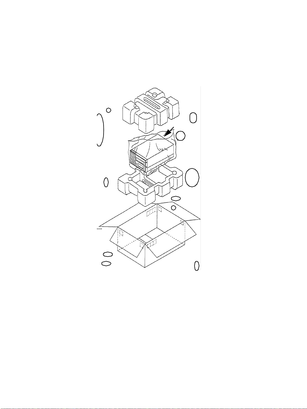
INSTALLATION INSTRUCTIONS M2488 PRODUCT GUIDE
1-4 UNPACKING INSTRUCTIONS
Use the following procedures to unpack the M2488 tape drive and its optional equipment. When the
equipment is unpacked, proceed to the inspection procedures in paragraph 1-5.
1-4.1 Unpack the M2488 Tape Drive
Unpack the M2488 tape drive as described below.
M2488
** NOTE **
The model shown is a M2488 without an ACL or FACL attached.
1. Carefully remove the M2488 from the packing material as shown in the figure above.
2. Place the tape drive on a flat work surface.
3. Verify contents of package to the packing list.
4. Retain packing material for future use.
5. Continue with unpacking the medium changer (if applicable) or inspect the equipment.
1-4 CG00000-011503 REV. A April 1997
Page 31

M2488 PRODUCT GUIDE INSTALLATION INSTRUCTIONS
1-4.2 Unpack the Automatic Cartridge Loader
Unpack the ACL as described below.
ACL
1. Carefully remove the ACL from the packing material and place on flat work surface.
2. Verify contents of package and accessory kit to the packing list.
3. Retain packing material for future use.
4. Continue with the equipment inspection instructions.
April 1997 CG00000-011503 REV. A 1-5
Page 32

INSTALLATION INSTRUCTIONS M2488 PRODUCT GUIDE
1-4.3 Unpack the Flush-mounted Automatic Cartridge Loader
Unpack the FACL as described below.
FACL
1. Carefully remove the FACL from the packing material and place on flat work surface.
2. Verify contents of package and the accessory kit to the packing list.
3. Remove packing material from the inside of the FACL. Press PUSH on the front panel to open
door. Press PUSH on the magazine tray and remove packing. Press PUSH again to close the
magazine tray, then press PUSH on the front panel to close door.
4. Retain packing material for future use.
5. Continue with the equipment inspection instructions.
1-6 CG00000-011503 REV. A April 1997
Page 33

M2488 PRODUCT GUIDE INSTALLATION INSTRUCTIONS
1-5 EQUIPMENT INSPECTION
After unpacking, inspect the equipment. If any damage is found, note the type of damage and location.
Also note any damage to the packing container. Contact your carrier for further instructions for handling the damaged equipment.
1-5.1 Inspect the M2488 Tape Drive
• Visually examine the chassis for dents and cracks.
Upon completion, inspect the medium changer, if applicable, or continue with the assembly instruc-
tions.
1-5.2 Inspect the ACL
• Visually examine the chassis for dents and cracks.
Upon completion, continue with the assembly instructions.
1-5.3 Inspect the FACL
• Visually examine the chassis for dents and cracks.
• Check the door lock by pressing on the lock lever and opening the door.
• Check the carrier movement by rotating the carrier knob. Refer to the Controls and Indicators section in Chapter 3 of the User’s Guide for the location of the knob.
Upon completion, continue with the assembly instructions.
April 1997 CG00000-011503 REV. A 1-7
Page 34

INSTALLATION INSTRUCTIONS M2488 PRODUCT GUIDE
1-6 ASSEMBLY INSTRUCTIONS
These paragraphs describe the assembly and installation of the M2488 tape drive and of the optional
equipment. Use the following flowchart to determine which procedures are applicable to your equipment configuration. The paragraph number for the procedure is listed in the flowchart with the procedure title.
Installation Procedures
General Instructions 1-6.1
ACL Installation
1-6.6
Prepare the M2488 Tape Drive
1-6.6.1
Prepare the ACL 1-6.6.2
Connect the M2488 and ACL
1-6.6.3
Rackmount Instructions
1-6.5
ACL (if unattached) FACL (if unattached)
ACL or
FACL?
No ACL/FACL or
ACL/FACL already
attached
Install IPM 1-6.2
Rackmount Desktop
Desktop or
Rackmount ?
FACL Installation
1-6.7
Prepare the M2488 Tape Drive
1-6.7.1
Prepare the FACL 1-6.7.2
Connect the M2488 and FACL
1-6.7.3
Desktop Instructions
1-6.4
Connect cables and power cord
1-6.3
Configure the drive 1-7
1-8 CG00000-011503 REV. A April 1997
Page 35

M2488 PRODUCT GUIDE INSTALLATION INSTRUCTIONS
1-6.1 General Installation and Assembly Instructions
1-6.1.1 Air Flow and Service Clearances
Allow a gap of 50 mm (2 inches) at the rear of the drive for heat dissipation.
Allow a 620 mm (24 inches) servicing area to the rear, with drive extended, for rack-mounted
drives.
1-6.2 Interface Personality Module Installation
** NOTE **
Prior to assembly, ensure all SCSI cables and power cords have
been disconnecte d. The M2488 should be placed as near as possible to the main AC outlet.
Installation of the IPM is described below.
IPM
Figure 1-1. IPM Installation
STEP ACTION
1 Insert the IPM, component side down, into the circuit board at the rear of the M2488. See Figure 1-1.
2 Insert and tighten two screws on the IPM.
April 1997 CG00000-011503 REV. A 1-9
Page 36

INSTALLATION INSTRUCTIONS M2488 PRODUCT GUIDE
1-6.3 Cable and Power Connections
Installation of the SCSI cables and power cord are described in the following paragraphs. The SCSI
connectors are described in the User’s Guide, Chapter 1.
** NOTE **
1. Cable and powe r conne c tions shoul d only be m ade upon completion of the M2488 hardware setup to include at tachment of optional
equipment. Use the appropriate assembly procedures for the desired
option.
2. Both S CSI con nectors on t he IPM m ust be connect ed. The connection may be either two SCSI cables or one SCSI cable and one
Terminator.
See Figure 1-2.
STEP ACTION
1 Attach SCSI cable to one of the SCSI connectors on the IPM (which of the tw o
connectors is not important).
2 Attach the Terminator or the second SCSI cable to the other SCSI connector
on the IPM.
3 Connect power cord.
Figure 1-2. Cable and Power Connections
1-10 CG00000-011503 REV. A April 1997
Page 37

M2488 PRODUCT GUIDE INSTALLATION INSTRUCTIONS
1-6.4 Desktop Installation Instructions
Use the procedure below for your configuration. When completed, continue with paragraph 1-6.3.
1-6.4.1 Tools Required
The following tools are required to install the M2488 in a desktop configuration:
Phillips screwdriver
Flat-head screwdriver
1-6.4.2 Tape Drive Only
If the two foot rails were removed, reattach and place drive in prepared location.
1-6.4.3 Drive with ACL Attached (5-Cartridge Magazine)
Use this procedure if the M2488 with attached ACL is to be used with a support base for a 5-cartridge magazine. Figure 1-3 shows the M2488 with an attached ACL in a desktop model.
STEP ACTION
1 Attach both foot rails to the M2488 with the four screws.
2 Place the M2488 with attached ACL into the support base.
3 Insert the projections of the rear bracket into the gap on each foot rail. Attach rear bracket with
two screws through the rear of the support base.
Figure 1-3. Drive with ACL (5-cartridge) Desktop Configuration
April 1997 CG00000-011503 REV. A 1-11
Page 38

INSTALLATION INSTRUCTIONS M2488 PRODUCT GUIDE
1-6.4.4 Drive with ACL Attached (10-Cartridge Magazine)
Use this procedure if the M2488 with attached ACL is to be used with a base for a 10-cartridge
magazine.
STEP ACTION
1 Place the support base onto the M2488A41 (10-cartridge base) and attach with the four
screws. See Figure 1-4.
2 For additional stability, attach the rubber feet and two metal brackets on the bottom of the
M2488A41 as shown in Figure 1-5 on page 1-13.
3 Place the drive with ACL on the support base. Move the drive forward and attach to the pro-
jections on the support base. See Figure 1-6 on page 1-13 and Figure 1-7 on page 1-14.
4 Insert the projections of the rear bracket into the gap on each foot rail. Attach rear bracket with
two screws through the rear of the support base. See Figure 1-8 on page 1-14.
Figure 1-4. Attaching Bases
1-12 CG00000-011503 REV. A April 1997
Page 39

M2488 PRODUCT GUIDE INSTALLATION INSTRUCTIONS
Figure 1-5. Stability Brackets
Figure 1-6. Drive Placement
April 1997 CG00000-011503 REV. A 1-13
Page 40

INSTALLATION INSTRUCTIONS M2488 PRODUCT GUIDE
Figure 1-7. Drive Positioning
Figure 1-8. Rear Bracket Attachment
1-14 CG00000-011503 REV. A April 1997
Page 41

M2488 PRODUCT GUIDE INSTALLATION INSTRUCTIONS
1-6.4.5 Drive with FACL Attached
Figure 1-9 shows the M2488 with an attached FACL in a desktop model.
Figure 1-9. M2488 with FACL in Desktop Model
Use the following procedure to insert the M2488 with attached FACL into the desktop model.
Refer to Figure 1-10 through Figure 1-12 during performance of this procedure.
STEP ACTION
1 Insert the M2488 with FACL into the bottom base. Attach through bottom of base into bottom
of M2488 and FACL with eight screws. See Figure 1-10.
2 Place the desktop cover over the M2488 and FACL. See Figure 1-11.
3 Tighten the eight screws into the sides of the bottom base.
4 Place rear cover over back opening and tighten with four screws. See Figure 1-12.
April 1997 CG00000-011503 REV. A 1-15
Page 42

INSTALLATION INSTRUCTIONS M2488 PRODUCT GUIDE
bottom
base
Figure 1-10. Attach to Bottom Base
1-16 CG00000-011503 REV. A April 1997
Page 43

M2488 PRODUCT GUIDE INSTALLATION INSTRUCTIONS
desktop cover
Figure 1-11. Desktop Model Top Covers
April 1997 CG00000-011503 REV. A 1-17
Page 44

INSTALLATION INSTRUCTIONS M2488 PRODUCT GUIDE
rear cover
Figure 1-12. Desktop Model Rear Cover
1-18 CG00000-011503 REV. A April 1997
Page 45

M2488 PRODUCT GUIDE INSTALLATION INSTRUCTIONS
1-6.5 Rack-Mount Installation
This procedure is for mounting the M2488 tape drive, with or without a medium changer, in the rackmount tray.
****************
CAUTION
* *
******************
The weight of the equipment may exceed 10kg, use caution when
mounting the tape drive and medium changer. Installation may
require two or more service personnel.
** NOTE **
Use M4 x 6mm length screws to mount the M2488 on the rackmounting tray.
1-6.5.1 Tools Required
The following tools are required to install the M2488 in a rack-mount configuration:
Phillips screwdriver
Hex wrench (M4)
Flat-head screwdriver
1-6.5.2 Adjust the Guide Plate
Refer to Figure 1-13 and Figure 1-14 for this procedure.
For a single drive configuration, the guide plate must be mounted as the guide for the inner cover
on the drive mounting side. The drive must be mounted on the right side and use the optional front
panel.
For a two drive configuration, the guide plate is not used.
1-6.5.2.1 Inner Cover Mounted to Mounting Tray
See Figure 1-13 (A).
STEP ACTION
1 Insert the inner cover from the front of the mounting tray and push it into the tray until the
stopper is locked.
2 Align the round bump at the center of the guide plate with the hole of the inner cover. Use two
bolts to attach guide plate.
1-6.5.2.2 Inner Cover NOT Mounted to Mounting Tray
See Figure 1-13 (B).
STEP
ACTION
1 Remove the inner cover from the mounting tray.
2 Align the round bump at the center of the guide plate with the hole of the mounting tray. Use
two bolts to attach guide plate.
April 1997 CG00000-011503 REV. A 1-19
Page 46

INSTALLATION INSTRUCTIONS M2488 PRODUCT GUIDE
Figure 1-13. Guide Plate Installation
1-6.5.3 Screw Plate Mounting
See Figure 1-14.
STEP ACTION
1 Each screw plate has nine holes. Mount the screw plate so that the big hole is up.
2 Attach 4 screw plates (g) to the rear of each pole of the rack with two screws (i -SBD-5x2S-M-
NI1A) in the top and bottom holes.
1-6.5.4 Attach Mounting Tray
See Figure 1-14.
NOTE: When the mounting hole of the rack is a screw hole, remove the positioning pins at both
the left and right sides of the tray (d) with a screwdriver.
STEP ACTION
1 Insert mounting tray (d) into the 19-inch rack and attach the front with six screws (j - SW2NA-
5x12S-M-NI1A).
2 Attach 2 brackets (f) to both the left and right sides of the tray (d) with six screws (k).
3 Attach brackets (f) to the left and right rear poles of the rack with eight screws (j) and tighten.
1-20 CG00000-011503 REV. A April 1997
Page 47

M2488 PRODUCT GUIDE INSTALLATION INSTRUCTIONS
Figure 1-14. 19-inch Rack-mount Kit Installation
April 1997 CG00000-011503 REV. A 1-21
Page 48

INSTALLATION INSTRUCTIONS M2488 PRODUCT GUIDE
1-6.5.5 Adjust the Brackets
The length of the bracket is adjusted according to length ‘L’ between the front and rear poles of the
19-inch rack. To adjust the length of the bracket, exchange the left and right brackets (as shown in
Figure 1-15) or replace the brackets with longer brackets.
Figure 1-15. Bracket Adjustment
1-22 CG00000-011503 REV. A April 1997
Page 49

M2488 PRODUCT GUIDE INSTALLATION INSTRUCTIONS
1-6.5.6 Install the M2488 or M2488 with Medium Changer on the Mounting Tray
Refer to Figure 1-14, Figure 1-16 through Figure 1-19 for this procedure.
NOTE: Before inserting, confirm that the inner cover is on the U-type slit of the mounting tray.
STEP ACTION
1 If a single drive is used, it must be mounted on the right side.
2 Remove the two foot rails from the drive (if installed).
3 Attach drive to the inner cover with four screws (p -CG001901-002).
If attached, the FACL should be flush with the front of the inner cover.
4 Attach the rear of the drive with one screw (r - SW3NA-3x12S-M-NI1A) through the L-type
bracket.
5 Use the correct faceplate (optional) for either a single or dual drives and attach to drives.
M2488
M2488 drive
Inner Cover
Mounting Tray
Front Panel
Figure 1-16. M2488 Tray Mounting
April 1997 CG00000-011503 REV. A 1-23
Page 50

INSTALLATION INSTRUCTIONS M2488 PRODUCT GUIDE
Figure 1-17. M2488 with ACL Tray Mounting
Inner Cover
Screws
Figure 1-18. Mount FACL to Inner Cover
1-24 CG00000-011503 REV. A April 1997
Page 51

M2488 PRODUCT GUIDE INSTALLATION INSTRUCTIONS
Front Panel
Mounting tray
Screws
Figure 1-19. FACL Face Plate
April 1997 CG00000-011503 REV. A 1-25
Page 52

INSTALLATION INSTRUCTIONS M2488 PRODUCT GUIDE
1-6.6 Installation of the Automatic Cartridge Loader
Perform the installation procedure for the ACL in the order presented in the following flowchart. The
paragraph for each procedure is included in the flowchart. Equipment and tools required for installation are listed in Table 1-3.
Table 1-3. Equipment and Tools Required for ACL Installation
EQUIPMENT PART NUMBER QUANTITY DESCRIPTION
ACL B03B-5400-H011A 1 Automatic Cartridge Loader
Allen bolts Part of ACL accessory kit 3 Used for attachment to drive
Grounding plate Part of ACL accessory kit. 1 Attaches between ACL and drive
Phillips #2 screwdriver 1
Allen wrench (5mm) 1 8 inches long
** NOTE **
1. ACL versions A0 through B6 are incompatible with the M2488 and
should not be attached to this drive.
2. The M2488 shoul d be powered o ff and all cable s and cords disconnected prior to performing this installation procedure. Follow
standard procedures and cautions used when handling electronic
equipment.
ACL Installation
Prepare the M2488 Tape Drive
1-6.6.1
Prepare the ACL
1-6.6.2
Connect the M2488 and ACL
1-6.6.3
1-6.3
1-26 CG00000-011503 REV. A April 1997
Page 53

M2488 PRODUCT GUIDE INSTALLATION INSTRUCTIONS
1-6.6.1 Prepare the M2488 Tape Drive
Refer to Figure 1-20, Figure 8-6 and Figure 8-7 during performance of this procedure.
STEP ACTION
1 Remove two screws from each of the foot rails on the bottom of the drive, then remove the foot
rails. See Figure 8-7.
2 Remove the top cover by removing the two screws from the left and right side, and the two screws
on the rear. Pull the cover up from the rear and slide backwards. See Figure 8-6.
****************
CAUTION
* *
******************
Remove the top cover by lifting the front of the top cover BEFORE sliding it
backwards. Ensure that the cover does not catch on the components on the
PCBA under the top cover.
3 Remove the four screws from the sides of the front panel, then gently pull the front panel forward.
4 Disconnect the operator panel cable from the front panel.
5 Remove the two screws holding the panel bracket, then pull off the panel bracket.
Figure 1-20. Prepare the M2488 Tape Drive
April 1997 CG00000-011503 REV. A 1-27
Page 54

INSTALLATION INSTRUCTIONS M2488 PRODUCT GUIDE
1-6.6.2 Prepare the ACL
Refer to Figure 1-21 during performance of this procedure.
STEP ACTION
1 Remove two screws (on the bottom front corners) from the ACL top cover.
2 Push down and hold the cover release bar while pulling up and slightly moving the top cover for-
ward. When the cover has cleared the hook on the top rear of the cover (behind the cover
release), continue to pull forward then up.
3 Remove the four screws from the bottom of the ACL and gently lift the ACL mechanism from
the base.
Bar
Figure 1-21. Prepare the ACL
1-28 CG00000-011503 REV. A April 1997
Page 55

M2488 PRODUCT GUIDE INSTALLATION INSTRUCTIONS
1-6.6.3 Connect the M2488 and the ACL
Refer to Figure 1-22 through Figure 1-25 during performance of this procedure.
STEP ACTION
1 Place the grounding plate on the front of the M2488 (replaces the front panel). See Figure 1-22.
2 Attach the ACL base to the front of the M2488 using the three Allen screws.
3 Pull operator panel cable through small hole on base.
4 Slide the ACL mechanism into the base. Leave slightly forward for cable connection.
5 Refer to Figure 1-23 and Figure1-24. Connect the cable to the ACL operator panel cable. Tuck
connector into hole in base. Remove protective sheet from adhesive tape inside the ACL base and
press the operator panel cable to the tape.
6 Attach the interface cable between the connector on the rear of the ACL and the connector on the
front of the M2488.
7 Push the mechanism all the way to the rear of the base. Insert the four screws through the ACL
base into the ACL mechanism and tighten.
8 Replace the ACL cover and tighten the two bottom corner screws (see Figure 1-25).
9 Replace the M2488 top cover and tighten the six screws.
Figure 1-22. Connect the M2488 and the ACL Base
April 1997 CG00000-011503 REV. A 1-29
Page 56

INSTALLATION INSTRUCTIONS M2488 PRODUCT GUIDE
excess cable
Figure 1-23. Attach Operator Panel Cable to ACL Base
Interface Cable
Figure 1-24. Attach the ACL Mechanism
1-30 CG00000-011503 REV. A April 1997
Page 57

M2488 PRODUCT GUIDE INSTALLATION INSTRUCTIONS
Figure 1-25. Replace Covers
April 1997 CG00000-011503 REV. A 1-31
Page 58

INSTALLATION INSTRUCTIONS M2488 PRODUCT GUIDE
1-6.7 Installation of the Flush-mount Automatic Cartridge Loader
** NOTE **
Use caution when handling the FACL. The cleaning cell protrudes
from the r ear of the FACL and coul d be damaged by mishandling.
DO NOT use for lifting.
Refer to Table 1-4 for a list of equipment required to install the FACL on the M2488 tape drive. The
following flowchart illustrations the sequence of installation.
Table 1-4. Equipment and Tools Required for FACL Installation
EQUIPMENT PART NUMBER QUANTITY DESCRIPTION
FACL CA01032-B001 1 Flush-mounted medium changer
Allen bolts Part of FACL accessory kit 3 Used for attachment to drive
Grounding plate Part of FACL accessory kit. 1 Attaches between FACL and drive
Phillips #2 screwdriver 1
Allen wrench (5mm) 1 8 inches long
** NOTE **
The M2488 should be pow ered off and all cabl es and cords di sconnected prior to performing this installation procedure. Follow standard procedures and cautions used when handling electronic
equipment.
FACL Installation
Prepare the M2488 Tape Drive
1-6.7.1
Prepare the FACL
1-6.7.2
Connect the M2488 and FACL
1-6.7.3
1-6.3
1-32 CG00000-011503 REV. A April 1997
Page 59

M2488 PRODUCT GUIDE INSTALLATION INSTRUCTIONS
1-6.7.1 Prepare the M2488 Tape Drive
Refer to Figure 1-26 during performance of this procedure.
STEP ACTION
1 Remove the bottom, and the left and right side covers. See Figure 8-7.
2 Remove the top cover by removing the two screws from the left and right side, and the two screws
on the rear. Pull the front of the cover up and slide backwards. See Figure 8-6.
****************
CAUTION
* *
******************
Remove the top cover by lifting the front of the top cover BEFORE sliding it
backwards. Ensure that the cover does not catch on the components on the
PCBA under the top cover.
3 Remove the four screws from the sides of the front panel, then gently pull the front panel forward.
4 Disconnect the operator panel cable from the front panel.
5 Remove the two screws holding the panel bracket, then pull off the panel br acket.
Figure 1-26. Prepare the M2488 Tape Drive
April 1997 CG00000-011503 REV. A 1-33
Page 60

INSTALLATION INSTRUCTIONS M2488 PRODUCT GUIDE
1-6.7.2 Prepare the FACL
Refer to Figure 1-27 and Figure 1-28 during performance of this procedure.
STEP ACTION
1 Remove the two screws from each of the covers.
2 Pull up on the two top cover halves and remove.
3 Pull the two cables, CNJ24 and CNJ28, through the square hole on the lower right rear of the
FACL. See Figure 1-28 for location.
Figure 1-27. Prepare the FACL
1-34 CG00000-011503 REV. A April 1997
Page 61

M2488 PRODUCT GUIDE INSTALLATION INSTRUCTIONS
Figure 1-28. FACL Rear
1-6.7.3 Connect the M2488 and the FACL
Refer to Figure 1-29 and Figure 1-30 during performance of this procedure.
STEP ACTION
1 Insert the grounding plate at the front of the M2488 drive as shown in Figure 1-29.
2 Connect the cable CNJ24 and CNJ28 to the M2488 connectors CNP24 and CNP28. Route the
CNJ24 cable through the inside of the corner post on the M2488. See Figure 1-30.
3 Align the positioning projections on the M2488 to the holes on the rear of the FACL. Attach the
three Allen bolts through the inside of the FACL into the grounding plate and tighten.
4 Replace the top covers on the FACL. Tighten four screws to hold the covers in place.
5 Replace the top cover on the M2488. Tighten the four screws to hold the cover in place. See
Figure 1-31.
April 1997 CG00000-011503 REV. A 1-35
Page 62

INSTALLATION INSTRUCTIONS M2488 PRODUCT GUIDE
Grounding plate
Figure 1-29. Connect the M2488 and the FACL
CNP24
CNJ24
Figure 1-30. Cable Connection
1-36 CG00000-011503 REV. A April 1997
Page 63

M2488 PRODUCT GUIDE INSTALLATION INSTRUCTIONS
Figure 1-31. Replace Top Covers
1-7 PREPARATION FOR USE
See the User’s Guide for configuration information.
April 1997 CG00000-011503 REV. A 1-37
Page 64

Page 65

M2488 PRODUCT GUIDE DESIGN ARCHITECTURE
CHAPTER 2
DESIGN ARCHITECTURE
2-1 INTRODUCTION
This chapters provides information on the principles of operation of the M2488 tape drive. This chapter
begins with a a high level description of the M2488, then progresses to a more detailed description of
the individual circuits. Refer to the appropriate paragraphs for the necessary level of detail.
2-2 OPERATION OF THE M2488
2-3 OPERATION OF THE MAGNETIC TAPE CONTROLLER (MTC)
2-4 OPERATION OF THE MAGNETIC TAPE UNIT (MTU)
2-2 OPERATION OF THE M2488
The following paragraphs describe the operation of the M2488. Refer to the block diagram in Figure 2-
1.
SCSI BUS
RS-232
IPM
PCA-DTC
DMD
WDATA
CP_BUS
Figure 2-1. M2488 Block Diagram
PCA-RDL
READ CIRCUIT
PCA-WTL
WRITE CIRCUIT
PCA-DVL
PCA-SVL
HEAD
PCA-OP
RS-232
The M2488 is a highly reliable, compact tape unit using IBM 3490/349E compatible half-inch tape cartridges. It is fully contained with the power supply integrated into the compact 8-inch form factor. The
M2488 architecture consists of the magnetic tape controller (MTC) which performs the host interface,
data buffering, compression, and formatter functions and the magnetic tape unit (MTU) that performs
the mechanical control and read/write functions. Descriptions of the MTC and MTU are presented in
the following sections.
April 1997 CG00000-011503 REV. A 2-1
Page 66

DESIGN ARCHITECTURE M2488 PRODUCT GUIDE
2-3 OPERATION OF THE MAGNETIC TAPE CONTROLLER (MTC)
The DTC PCA contains all of the MTC (Magnetic Tape Controller) logic in a highly integrated implementation. This double-sided PCBA has extensive VLSI for reduced cost and increased reliability. The
M2488 uses one of four Interface Personality Modules (IPM) to configure the SCSI-2 interface for the
four combinations of wide or narrow and differential or single-ended operation.
The main functions contained on the DTC PCBA include:
1) Main Processor with all associated memory and support logic
2) Full SCSI-2 interface with RISC-based SCSI Protocol Controller (SPC)
3) 20 MB/s Host data path with EDRC logic
4) 2 MB Data Buffer
5) MTU (Formatter) digital read/write logic.
The processes performed by the DTC involve coordination of M2488 operation by the Main Processor
(CP):
- High-level SCSI I/F control of SPC
- Full control of data transfers on Host and MTU Data Paths
- Active Data Buffer management
- High-level control of MTU servo (tape motion)
Refer to the block diagram in Figure 2-2.
2-3.1 Data Path
The M2488 data path has been designed to allow data transfers up to a rate of 10Mbyte/s on a single
or two-byte wide SCSI interface and data transfers up to 20 Mbyte/s across a two-byte bus into the
controller buffer.
The SPC used is the Fujitsu MB86603 which is a fast and wide capable protocol controller intended
for high-performance systems. This controller operates in target mode and supports synchronous or
asynchronous data transfers. Performance enhancing features of the MB86603 are:
1) Programmable commands (512 bytes internal program memory).
2) Data FIFO register (64 bytes).
3) Automatic selection, reselection retry, and attention handling (e.g. combined sequences that
allow hardware to handle all SCSI protocols up through CDB acquisition).
4) Support of high-level commands.
Various data transfer rates can be set by programming the SPC internally from the default clock rate
of 20 MHz or an alternate 30 MHz clock.
2-3.2 Data Buffer
The remaining data path functions; host interface logic, host packet processor, buffer function control, and formatter packet processor; have been combined into a single data path LSI (SDDP). Buffer
performance has also been greatly enhanced. The SDDP buffer function control supports a three port
buffer with a 32 Mbyte/s bandwidth and 20 MHz clock. This allows 20 Mbyte/s data transfer rate on
the host port, up to 10 Mbyte/s burst transfers on the formatter port, and a microprocessor port overhead up to 2 Mbyte/s. The host port is two bytes wide and the formatter port is a single byte wide.
The SDDP can support up to 8 Mbyte of buffer memory with a standard size of 2 Mbyte for the
M2488.
2-3.3 ERDC Compression Feature
Compression is performed by an improved design EDRC chip set prior to the data buffer. Placement
of compression before the buffer effectively extends buffer capacity by a factor equal to the average
compression rate. It also allows packet headers, which contain compression information for the entire
2-2 CG00000-011503 REV. A April 1997
Page 67

M2488 PRODUCT GUIDE DESIGN ARCHITECTURE
SCSI
DRIVERS
RECEIVERS
SCSI BUS
SN75LBC976
CP
MICROPROCESSOR
MB86930
SPARC lite
SCSI
PROTOCOL
CONTROLLER
MB86603
2 - 256K x 18
(1 Mbyte CS)
Figure 2-2. DTC PCA Block Diagram
18
FIFO SRAM
SRAM
32K x 16
CP BUS
DRAM
DATA BUFFER
WITH EDRC
FORMATTING
NVRAM
MB8486A
8k x 8
4- 256K x 18
DRAM
SDDP
SG
(SGC)
CE
SG
(SGD)
DE
FLASH
MASKROM
2 x 512K x 8
EDRC COMPRESSION
PROCESSOR
COMPANION
CP BUS
CHIP
(RSVP Contr o lle r)
9
PCC
DRV/RCV
9
FORM ATTE R
WFMT
AXP
DSKW
CP BUS
RCTL
RSVP_I/F
WRITE
HEAD
LOGIC
RS
READ
HEAD
LO GIC
SERVO PR OCE SSO R
RS232
INT ERFACE
SHARED RAM
packet, to be built without requiring additional buffering. Data buffering increases overall performance by allowing data streaming since the buffer can mask or eliminate some tape repositions.
The EDRC chip set consists of a compression engine (CE), a decompression engine (DE), and a data
control function (SG). The SG LSI is used twice in the design, once each for the CE and DE. The
complete chip set is designed to operate at the full data path rate of 20 MB/s. In addition, The compression SG input FIFO is 64k bytes for compression data caching. If compression retries are ever
required, retries can automatically be performed without host intervention.
2-3.4 Microprocessor Control
A 20MHz MB68930 Sparc-lite MPU is the single Control Processor (CP) used for the controller
requirements. The controller CP communicates directly to the drive servo CP via dual-port RAM.
The RSVP (Read Signal Verification Processor) is a 10 Mhz, 24-bit, fixed instruction sequencer that
is embedded inside the PCC (Processor Companion Chip). It requires less than 4200 basic cells of the
22,800 cells in the PCC. The RSVP provides the dedicated formatter signal processing needed to
support the CP with the time critical formatter control. It allows the controller firmware architecture
to use event driven multi-tasking for the CP code and allow the RSVP to handle dedicated read signal
polling. The RSVP presents interrupts to the CP based on drive read interface signals which are preprocessed; polled, monitored, filtered, and conditioned as required.
April 1997 CG00000-011503 REV. A 2-3
Page 68

DESIGN ARCHITECTURE M2488 PRODUCT GUIDE
2-3.5 Firmware
The M2488 microcode is partitioned into functional modules and stored in mask ROM and flash
memory. The code partitions serve to minimize communication paths within the code structure and to
segregate functions dealing with the host interface from those dealing with generic tape operation.
The mask ROM provides a resident code version for power-on and code download. New code versions are downloaded into flash memory from the host SCSI interface or from tape. After power-on,
control store for all processors is loaded from flash memory if valid. If invalid, the mask ROM code is
used for recovery.
The core microcode is a multi-tasking operating system (OS) allowing a configurable number of
tasks. The present design allows a total of thirty two active tasks; four fixed tasks and twenty-eight
SCSI tasks. T his custom OS al lows functi ons to run unti l a resource is una vailabl e, places itself int o a
suspended state until the resource becomes available, and then proceeds with execution. Many overlapped operations are possible because of a sophisticated interrupt structure. Servo, formatter, maintenance, and SCSI events are signalled via interrupts which in turn initiate processes via the OS to
service the events. Signals generated from the read detection circuitry are given highest priority by
polling them with the read signal verification processor (RSVP) embedded in the PCC LSI.
2-4 OPERATION OF THE MAGNETIC TAPE UNIT (MTU)
The magnetic tape unit consists of the read and write head, all mechanical assemblies (loader assembly,
threader assembly, and servo motors), and five printed circuit assemblies that perform the following
functions:
1) DVL PCA - control processor and logic for all servo and mechanical control functions. and operator panel control processor. A logical block diagram for the DVL is shown in Figure 2-3. The
interface and control logic is integrated into the MMCL LSI (denoted by the dotted line in the
block diagram).
2) OP PCA - contains the M2488 unit operator panel and associated drive circuitry
3) SVL PCA - contains servo control circuitry including I/O registers, control logic LSI, PWM control, and control DAC.
4) WTL PCA - contains the write drive circuits.
5) RDL PCA - contains the read analog circuits.
Other features of the MTU are described in the following sections.
2-4.1 Airless Tape Path
The M2488 has been able to realize an airless tape path while maintaining excellent reliability. This
system removes the failure-prone pump and pack arm assemblies with an improved roller guide tape
path. One new roller guide has been added that replaces the pack arm to keep tape aligned with the
tape machine reel. Alignment of tape with the head is accomplished with two roller guides as in previous models. Du ring running, a slight air film is produced between the he ad and tape whic h prevents
direct contact. A patrol reposition function has been added that periodically moves the tape to prevent
any problem when tape is not moving.
The reel motor of the M2488 has also been changed to dramatically improve tape reposition time and
access times.
2-4 CG00000-011503 REV. A April 1997
Page 69

M2488 PRODUCT GUIDE DESIGN ARCHITECTURE
PCA-DV L
gate
Servo Proc
68000
DTC_present
gate
I/O R e g sOP Regs
RAM
Dual Port
MMCL
ACC/ACL
ROM
Counters
8752
Figure 2-3. DVL PCA Block Diagram
SRAM
UART
SV Reg
PCA-OP
OP...PANEL
RS-232
2-4.2 Read and Write Electronics
The read circuits for the M2488 utilize fifteen analog LSI that were developed for the M2483. These
components have been field proven to be a stable and low cost design.
The write circuits of the M2488 use enhanced head driver ICs developed with the latest semiconductor technology. This technology allows the integration of six write channels (tracks) into one chip.
April 1997 CG00000-011503 REV. A 2-5
Page 70

DESIGN ARCHITECTURE M2488 PRODUCT GUIDE
2-6 CG00000-011503 REV. A April 1997
Page 71

M2488 PRODUCT GUIDE SCSI MESSAGES
CHAPTER 3
SCSI MESSAGES
3-1 INTRODUCTION
Chapters 3 through 6 are the Host Interface Specification for the M2488.
This chapter describes the messages for the M2488 tape drive and the med ium changers. The following
information is located in this chapter:
3-2 M2488 TAPE AND MEDIUM CHANGER SCSI MESSAGES
3-3 SCSI BUS STATUS
3-2 M2488 TAPE AND MEDIUM CHANGER SCSI MESSAGES
Table 3-1 describes the SCSI messages used with the M2488. For more detailed information on the
SCSI message, refer to the paragraph listed in the PARAGRAPH column.
Table 3-1. M2488 SCSI Messages
CODE MESSAGE DESCRIPTION PARAGRAPH
00h COMMAND COMPLETE
01h EXTENDED MESSAGE Sent as the first byte of a multiple-byte message. 3-2.5 on page 3-3
02h SAVE DATA POINTER
03h RESTORE POINTERS
04h DISCONNECT
05h INITIATOR DETECTED ERROR Informs a target an error has occurred. 3-2.8 on page 3-8
06h ABORT Sent to the target to clear the present operation. 3-2.1 on page 3-2
07h MESSAGE REJECT
08h NO OPERATION
09h MESSAGE PARITY ERROR
0Ah
LINKED COMMAND COMPLETE
Indicates the execution of a command has terminated and valid status was sent to the initiator.
Directs the initiator to save a copy of the present
active data pointer for the currently attached logical unit.
Restores the most recently saved point ers (for the
currently attached logical unit) to the active state.
Informs the initiator that the present physical
path is going to be broken.
Indicates the last message received was inappropriate or was not implemented.
Sent in response to a target’s request for a message when the initiator does not currently have
any other valid message to send.
Indicates one or more bytes in the last message,
received by the initiator, had a parity error.
Indicates to the initiator that the completion and
execution of a linked command and status was
sent.
3-2.3 on page 3-2
3-2.15 on page 3-9
3-2.14 on page 3-9
3-2.4 on page 3-2
3-2.12 on page 3-8
3-2.13 on page 3-9
3-2.11 on page 3-8
3-2.9 on page 3-8
Indicates to the initiator that the completion and
execution of a linked command with the flag bit
set to 1 and status was sent.
3-2.10 on page 3-8
0Bh
LINKED COMMAND COMPLETE (with flag)
April 1997 CG00000-011503 REV. A 3-1
Page 72

SCSI MESSAGES M2488 PRODUCT GUIDE
Table 3-1. M2488 SCSI Messages (Continued)
CODE MESSAGE DESCRIPTION PARAGRAPH
0Ch BUS DEVICE RESET
23h IGNORE WIDE RESIDUE
80h-
FFh
IDENTIFY
3-2.1 ABORT code 06h
This message is sent from the initiator to the target to clear the present operation.
If a logical unit has been identified, all pending data and status for the issuing initiator from the
affected logical unit are cleared, and the target goes to the BUS FREE phase. Pending data and status
for other initiators are not cleared. If a logical unit is not identified, the target goes to the BUS FREE
phase. No status or ending message is sent for the operation. It is not an error to issue this message to
a logical unit that is not currently performing an operation for the initiator.
3-2.2 BUS DEVICE RESET code 0Ch
This message is sent from an initiator to direct a target to clear all current commands on that SCSI
device.
Directs the target to clear all current commands
on that SCSI device.
Sent to an initiator to indicate the number of
valid bytes sent during the last REQ/ACK handshake and REQB/ACKB handshake of a DATA
IN phase is less than the negotiated transfer
width.
Sent to establish the physical path connection
between an initiator and target for a particular
logical unit.
3-2.2 on page 3-2
3-2.7 on page 3-7
3-2.6 on page 3-7
This message forces the SCSI device to an initial state with no operations pending for any initiator.
Upon recognizing this message, the target goes to the BUS FREE phase.
3-2.3 COMMAND COMPLETE code 00h
This message is sent from a target to an initiator to indicate the execution of a command or a series of
linked commands has terminated and valid status was sent to the initiator.
After successfully sending this message, the target goes to the BUS FREE phase by releasing BSY.
The target considers the message transmission to be successful when it detects the negation of ACK
for the COMMAND COMPLETE message with the ATN signal false.
The command m ay have been ex ecuted successf ully or uns uccessfully as indicated in the status.
3-2.4 DISCONNECT code 04h
This message is sent from a target to inform the initiator that the present physical path is going to be
broken (the target plans to disconnect by releasing BSY), but a later reconnect is required in order to
complete the current operation.
This message does not cause the initiator to save the data pointer. After successfully sending this
message, the target goes to the BUS FREE phase by releasing BSY. The target considers the message
transmission to be successful when it detects the negation of ACK for the DISCONNECT message
with the ATN signal false.
** NOTE **
3-2 CG00000-011503 REV. A April 1997
Page 73

M2488 PRODUCT GUIDE SCSI MESSAGES
3-2.5 EXTENDED MESSAGE FORMAT code 01h
This message is sent from either the initiator or the target as the first byte of a multiple-byte message.
CODE MESSAGE
01h Synchronous Data Transfer Request 5
03h Wide Data Transfer Request 4
3-2.5.1 Synchronous Data Transfer Request (SDTR)
BITS
BYTES
0
1
2
3
4
7 6 5 4 3 2 1 0
Extended Message (01h)
Extended Message Length (03h)
SYNCHRONOUS DATA TRANSFER REQUEST code (01h)
Transfer Period Factor
REQ/ACK Offset
A SYNCHRONOUS DATA TRANSFER REQUEST (SDTR) message exchange is initiated by a
SCSI device whenever a previously arranged data transfer agreement may have become invalid.
The agreement becomes invalid after any condition which may leave the data transfer agreement
in an indeterminate state such as:
LENGTH
(BYTES)
a) after a hard reset condition;
b) after a BUS DEVICE RESET message and;
c) after a power cycle.
In addition, a SCSI device may initiate an SDTR message exchange whenever it is appropriate to
negotiate a new data transfer agreement (either synchronous or asynchronous). SCSI devices that
are capable of synchronous data transfers shall not respond to an SDTR message with a MESSAGE REJECT message.
Renegotiation at every selection is not recommended, since a significant performance impact is
likely.
The SDTR message exchange establishes the permissible transfer periods and the REQ/ACK offsets for all logical units and target routines on the two devices. This agreement only applies to
data phases.
Byte 3: The transfer period factor times four is the value of the transfer period. The transfer period
is the minimum time allowed between leading edges of successive REQ pulses and of successive
ACK pulses to meet the device requirements for successful reception of data.
Byte 4: The REQ/ACK offset is the maximum number of REQ pulses allowed to be outstanding
before the leading edge of its corresponding ACK pulse is received at the target. This value is chosen to prevent overflow conditions in the device's reception buffer and offset counter. A REQ/
ACK offset value of zero shall indicate asynchronous data transfer mode; a value of FFh shall indicate unlimited REQ/ACK offset.
April 1997 CG00000-011503 REV. A 3-3
Page 74

SCSI MESSAGES M2488 PRODUCT GUIDE
** NOTE **
The supported SCSI transfer rates are listed in Appendix G.
The originating device (the device that sends the first of the pair of SDTR messages) sets its values
according to the rules above to permit it to receive data successfully. If the responding device can
also receive data successfully with these values (or smaller transfer periods or larger REQ/ACK
offsets or both), it returns the same values in its SDTR message. If it requires a larger transfer
period, a smaller REQ/ACK offset, or both in order to receive data successfully, it substitutes values in its SDTR message as required, returning unchanged any value not required to be changed.
Each device when transmitting data respects the limits set by the other's SDTR message, but it is
permitted to transfer data with larger transfer periods, smaller REQ/ACK offsets, or both than
specified in the other's SDTR message. The successful completion of an exchange of SDTR messages implies an agreement as follows:
Responding device SDTR response Implied agreement
a) Non-zero REQ/ACK offset Each device transmits data with a transfer period equal
to or greater than and a REQ/ACK offset equal to or
less t han the values received in the other device' s SDTR
messa ge .
b) REQ/ACK offset equal to zero Asynchronous transfer
c) MESSAGE REJECT message Asynchronous transfer
If the initiator recognizes that negotiation is required, it asserts the ATN signal and sends a SDTR
message to begin the negotiating process. After successfully completing the MESSAGE OUT
phase, the target shall respond with the proper SDTR message. If an abnormal condition prevents
the target from returning an appropriate response, both devices shall go to asynchronous data
transfer mode for data transfers between the two devices.
Following target response (a) above, the implied agreement for synchronous operation shall be
considered to be negated by both the initiator and the target if the initiator asserts the ATN signal
and the first message out is either MESSAGE PARITY ERROR or MESSAGE REJECT. In this
case, both devices shall go to asynchronous data transfer mode for data transfers between the two
devices. For the MESSAGE PARITY ERROR case, the implied agreement shall be reinstated if a
retransmittal of the second of the pair of messages is successfully accomplished. After a vendorspecific number of retry attempts (greater than zero), if the target receives a MESSAGE PARITY
ERROR message, it shall terminate the retry activity. This may be done either by changing to any
other information transfer phase and transferring at least one byte of information or by going to the
BUS FREE phase. The initiator shall accept such action as aborting the negotiation, and both
devices shall go to asynchronous data transfer mode for data transfers between the two devices.
If the target recognizes that negotiation is required, it sends an SDTR message to the initiator.
Prior to releasing the ACK signal on the last byte of the SDTR message from the target, the initiator shall assert the ATN signal and respond with its SDTR message or with a MESSAGE REJECT
message. If an abnormal condition prevents the initiator from returning an appropriate response,
both devices shall go to asynchronous data transfer mode for data transfers between the two
devices.
Following an initiator's responding SDTR message, an implied agreement for synchronous operation shall not be considered to exist until the target leaves the MESSAGE OUT phase, indicating
that the target has accepted the negotiation. After a vendor-specific number of retry attempts
3-4 CG00000-011503 REV. A April 1997
Page 75

M2488 PRODUCT GUIDE SCSI MESSAGES
(greater than zero), if the target has not received the initiator's responding SDTR message, it shall
go to the BUS FREE phase without any further information transfer attempt. This indicates that a
catastrophic error condition has occurred. Both devices shall go to asynchronous data transfer
mode for data transfers between the two devices.
If, following an initiator's responding SDTR message, the target shifts to MESSAGE IN phase and
the first message in is MESSAGE REJECT, the implied agreement shall be considered to be
negated and both devices shall go to asynchronous data transfer mode for data transfers between
the two devices.
The implied synchronous agreement shall remain in effect until a BUS DEVICE RESET message
is received, until a hard reset condition occurs, or until one of the two SCSI devices elects to modify the agreement. The default data transfer mode is asynchronous data transfer mode. The
default data transfer mode is entered at power on, after a BUS DEVICE RESET message, or after
a hard reset condition.
3-2.5.2 Wide Data Transfer Request (WDTR)
BITS
BYTES
0
1
2
3
7 6 5 4 3 2 1 0
Extended Message (01h)
Extended Message Length (02h)
WIDE DATA TRANSFER REQUEST code (03h)
Transfer Width Exponent
A WIDE DA TA TRA NSFER REQUEST (WD TR) mes sage e xchange i s ini tiated by a SC SI devi ce
whenever a previously arranged transfer width agreement may have become invalid. The agreement becomes invalid after any condition which may leave the data transfer agreement in an indeterminate state such as:
a) after a hard reset condition;
b) after a BUS DEVICE RESET message and;
c) after a power cycle.
In addition, an SCSI device may initiate a WDTR message exchange whenever it is appropriate to
negotiate a new transfer width agreement. SCSI devices that are capable of wide data transfers
(greater than eight bits) do not respond to a WDTR message with a MESSAGE REJECT message.
Renegotiation at every selection is not recommended, since a significant performance impact is
likely.
The WDTR message exchange establishes an agreement between two SCSI devices on the width
of the data path to be used for DATA phase transfers between the two devices. This agreement
applies to DATA IN and DATA OUT phases only. All other information transfer phases shall use
an eight-bit data path.
If an SCSI device implements both wide data transfer option and synchronous data transfer option,
then it shall negotiate the wide data transfer agreement prior to negotiating the synchronous data
transfer agreement. If a synchronous data transfer agreement is in effect, then an SCSI device that
accepts a WDTR message shall reset the synchronous agreement to asynchronous mode.
April 1997 CG00000-011503 REV. A 3-5
Page 76

SCSI MESSAGES M2488 PRODUCT GUIDE
Byte 3: The transfer width is two to the transfer width exponent bytes wide. The transfer width
that is established applies to all logical units on both SCSI devices. Valid transfer widths are 8 bits
(m = 00h), 16 bits (m = 01h), and 32 bits (m = 02h). Values of m greater than 02h are reserved.
The originating SCSI device (the SCSI device that sends the first of the pair of WDTR messages)
sets its transfer width value to the maximum data path width it elects to accommodate. If the
responding SCSI device can also accommodate this transfer width, it returns the same value in its
WDTR message. If it requires a smaller transfer width, it substitutes the smaller value in its
WDTR message. The successful completion of an exchange of WDTR messages implies an
agreement as follows:
Responding device WDTR response Implied agreement
a) Non-zero transfer width Each device transmits and receives data with a transfer
width equal to the responding SCSI device's transfer
width.
b) Transfer width equal to zero Eight-bit data transfer
c) MESSAGE REJECT message Eight-bit data transfer
If the initiator recognizes that negotiation is required, it asserts the ATN signal and sends a WDTR
message to begin the negotiating process. After successfully completing the MESSAGE OUT
phase, the target shall respond with the proper WDTR message. If an abnormal condition prevents
the target from returning an appropriate response, both devices shall go to eight-bit data transfer
mode for data transfers between the two devices.
Following target response a) above, the implied agreement for wide data transfers shall be considered to be negated by both the initiator and the target if the initiator asserts ATN and the first message out is either MESSAGE PARITY ERROR or MESSAGE REJECT. In this case, both devices
shall go to eight-bit data transfer mode for data transfers between the two devices. For the MESSAGE PARITY ERROR case, the implied agreement shall be reinstated if a retransmittal of the
second of the pair of messages is successfully accomplished. After a vendor-specific number of
retry attem pts (greate r than zero), if the target recei ves a MES SAGE PARI TY ERROR messag e, it
shall terminate the retry activity. This may be done either by changing to any other information
transfer phase and transferring at least one byte of information or by going to the BUS FREE
phase. The initiator shall accept such action as aborting the negotiation, and both devices shall go
to eight-bit data transfer mode for data transfers between the two devices.
If the target recognizes that negotiation is required, it sends a WDTR message to the initiator.
Prior to releasing the ACK signal on the last byte of the WDTR message from the target, the initiator shall assert the ATN signal and respond with its WDTR message or with a MESSAGE
REJECT message. If an abnormal condition prevents the initiator from returning an appropriate
response, both devices shall go to eight-bit data transfer mode for data transfers between the two
devices.
Following an initiator's responding WDTR message, an implied agreement for wide data transfer
operation shall not be considered to exist until the target leaves the MESSAGE OUT phase, indicating that the target has accepted the negotiation. After a vendor-specific number of retry
attempts (greater than zero), if the target has not received the initiator's responding WDTR message, it shall go to the BUS FREE phase without any further information transfer attempt (see
6.1.1). This indicates that a catastrophic error condition has occurred. Both devices shall go to
eight-bit data transfer mode for data transfers between the two devices.
3-6 CG00000-011503 REV. A April 1997
Page 77

M2488 PRODUCT GUIDE SCSI MESSAGES
If, following an initiator's responding WDTR message, the target shifts to MESSAGE IN phase
and the first message in is MESSAGE REJECT, the implied agreement shall be considered to be
negated and both devices shall go to eight-bit data transfer mode for data transfers between the two
devices.
The implied transfer width agreement shall remain in effect until a BUS DEVICE RESET message is received, until a hard reset condition occurs, or until one of the two SCSI devices elects to
modify the agreement. The default data transfer width is eight-bit data transfer mode. The default
data transfer mode is entered at power on, after a BUS DEVICE RESET message, or after a hard
reset condition.
Note: we recommend testing at INQUIRY DATA byte seven (07h) bits six and 5 (60h) to determine if the M2488 has an installed 16 bit interface (20h) and, therefore, supports WDTR with a
transfer width of 01h (16 bits). If the 16 bit interface is not installed. Then negotiation for 16 bits is
not recommended, since the negotiation will be rejected and a significant performance impact is
likely.
3-2.6 IDENTIFY code 80h-FFh
These messages are sent by either the initiator or the target to establish the physical path connection
between an initiator and target for a particular logical unit. The logical unit number addresses one of
up to eight physical or virtual devices attached to a target.
Bit 7 This bit is set to one to distinguish an IDENTIFY message from other messages.
Bit 6 This bit is only set to one by the initiator to grant the target the privilege of disconnecting. If
this bit is zero, the target does not disconnect. This bit is set to zero if sent by the target. Reference sections 8-6 ERROR RECOVERY PROCEDURES and 4-4 COMMAND DISCONNECTION for additional information on this bit.
Bit 5 LUNTAR = 0 to specify target LUN in bits 2-0.
Bits 4-3 Reserved.
Bits 2-0 These bits specify a LUN in a target.
Only one logical unit number is identified for any one selection sequence; a second IDENTIFY message with a new logical unit number is not issued before the bus is released (BUS FREE phase). The
initiator may send one or more IDENTIFY messages during a selection sequence. However, the logical unit number in any additional IDENTIFY messages is the same as the logical unit number specified in the first IDENTIFY message sent by the initiator.
When sent from a target to an initiator during reconnection, an implied RESTORE POINTERS message is performed by the initiator prior to completion of this message.
3-2.7 IGNORE WIDE RESIDUE code 23h
BYTE VALUE DESCRIPTION
0 23h Message Code
1 01h, 02h, 03h Ignore
This message is sent from a target to an initiator to indicate the number of valid bytes sent during the
last REQ/ACK handshake and REQB/ACKB handshake of a DATA IN phase is less than the negotiated transfer width. The ignore field indicates the number of invalid data bytes transferred. This message is sent immediately following that DATA IN phase and prior to any other messages. The ignore
field is defined in Table 3-2.
April 1997 CG00000-011503 REV. A 3-7
Page 78

SCSI MESSAGES M2488 PRODUCT GUIDE
Table 3-2. Ignore Field Description
INVALID DATA BITS
IGNORE
32-BIT TRANSFERS 16-BIT TRANSFERS
00h Reserved Reserved
01h DB (31-24) DB (15-8)
02h DB (31-16) Reserved
03h DB (31-8) Reserved
04-FFh Reserved Reserved
3-2.8 INITIATOR DETECTED ERROR code 05h
This message is sent from an initiator to inform a target an error (e.g., parity error) has occurred that
does not preclude the target from retrying the operation. Although present pointer integrity is not
assured, a RESTORE POINTERS message or a disconnect followed by a reconnect, causes the
pointers to be restored to their defined prior state.
The message is rejected unless it occurs immediately following a DATA or STATUS TRANSFER
phase.
3-2.9 LINKED COMMAND COMPLETE code 0Ah
This message is sent by a target to an initiator to indicate the completion and execution of a linked
command and status was sent. The initiator sets the pointers to the initial state for the next linked
command.
3-2.10 LINKED COMMAND COMPLETE (WITH FLAG) code 0Bh
This message is sent from a target to an initiator to indicate the execution of a linked command, with
the flag bit set to one, has completed and that status was sent. The initiator sets the pointers to the initial state of the next linked command. Typically this message is used to cause an interrupt in the initiator between two linked commands.
3-2.11 MESSAGE PARITY ERROR code 09h
This message is sent from the initiator to the target to indicate one or more bytes in the last message
it received had a parity error.
In order to indicate its intentions of sending this message, the initiator asserts the ATN signal prior to
its release of ACK for the REQ/ACK handshake of the message that has the parity error. This provides an interlock so the target can determine which message has the parity error.
The message is rejected unless it occurs immediately following a MESSAGE IN phase.
3-2.12 MESSAGE REJECT code 07h
This message is sent from either the initiator or target indicating the last message it received was
inappropriate or was not implemented.
In order to indicate its intentions of sending this message, the initiator asserts the ATN signal prior to
its release of ACK for the REQ/ACK handshake of the message that is to be rejected. If the target
receives this message under any other circumstance, the target rejects this message.
3-8 CG00000-011503 REV. A April 1997
Page 79

M2488 PRODUCT GUIDE SCSI MESSAGES
When a target sends this message, it changes to MESSAGE IN phase and sends this message prior to
requesting additional message bytes from the initiator. This provides an interlock so that the initiator
can determine which message was rejected.
3-2.13 NO OPERATION code 08h
This message is sent from an initiator in response to a target’s request for a message when the initiator does not currently have any other valid message to send.
3-2.14 RESTORE POINTERS code 03h
This message is sent from a target to direct the initiator to restore the most recently saved pointers,
for the currently attached logical unit, to the active state. Pointers to the command, data, and status
locations for the logical unit are restored to the active pointers. Command and status pointers are
restored to the beginning of the present command and status areas. The data pointer is restored to the
value at the beginning of the data area in the absence of a SAVE DATA POINTER message or to the
value at the point at which the last SAVE DATA POINTER message occurred for that logical unit.
** NOTE **
If a DISCONNECT message is used to break a long data transfer into
two or more shorter transfers, then a SAVE DATA POINTER is
issued before each DISCONNECT message.
3-2.15 SAVE DATA POINTER code 02h
This message is sent from a target to direct the initiator to save a copy of the present active data
pointer for the currently attached logical unit.
April 1997 CG00000-011503 REV. A 3-9
Page 80

SCSI MESSAGES M2488 PRODUCT GUIDE
3-3 SCSI BUS STATUS
A status byte, Table 3-3, is sent from the target to the initiator during the STATUS phase at the termination of each command unless the command is cleared by:
An ABORT message,
A BUS DEVICE RESET message,
A “hard” RESET condition, or
An unexpected BUS FREE condition.
Table 3-3. Status Byte
BITS
BYTES 7 6 5 4 3 2 1 0
0
Table 3-4 describes the status byte codes:
Reserved Status Byte Code Reserved
Table 3-4. Status Byte Code Bit Values
STATUS BYTE BITS
7 6 5 4 3 2 1 0
R R 0 0 0 0 0 R Good
R R 0 0 0 0 1 R Check condition
R R 0 0 0 1 0 R Condition met/good *
R R 0 0 1 0 0 R Busy
R R 0 1 0 0 0 R Intermediate/good
R R 0 1 0 1 0 R Intermediate condition met/good *
R R 0 1 1 0 0 R Reservation conflict
R R 1 0 0 0 1 R Command terminated *
R R 1 0 1 0 0 R Queue full *
All Other Codes Reserved
R- Reserved bit
*- Not supported by this controller
3-3.1 Good Status
This status indicates the target has successfully completed the command.
3-3.2 Check Condition
Any error, exception, or abnormal condition that causes sense data to be set, causes a CHECK CONDITION status. The REQUEST SENSE command is issued following a CHECK CONDITION status, to determine the nature of the condition.
3-3.3 Busy Status
STATUS REPRESENTED
The target is busy. This status is returned whenever a target is unable to accept a command from an
otherwise accept able initiator . The normal initiat or recovery acti on is to issue t he comman d again at a
later time.
3-3.4 Intermediate Status
This status is returned for every command in a series of linked commands (except the last command),
unless an error, exception, or abnormal condition causes a CHECK CONDITION status or a RESER-
3-10 CG00000-011503 REV. A April 1997
Page 81

M2488 PRODUCT GUIDE SCSI MESSAGES
VATION CONFLICT status to be set. If this status is not returned, the chain of linked commands is
broken; no further commands in the series are executed.
1. Intermediate/good. The Intermediate/good status is returned if the command completed successfully and is linked. If not linked, Good status is returned.
2. Intermediate/condition met/good. Not used.
3-3.5 Reservation Conflict Status
This status is returned whenever a SCSI device attempts to access a logical unit that is reserved with
a conflicting reservation type for another SCSI device (see RESERVE UNIT 16h command). The
normal initiator recovery action is to issue the command again at a later time.
April 1997 CG00000-011503 REV. A 3-11
Page 82

Page 83

M2488 PRODUCT GUIDE TAPE UNIT SCSI COMMANDS
CHAPTER 4
TAPE UNIT SCSI COMMANDS
4-1 INTRODUCTION
This chapter describes the commands and messages for the M2488. The following information is
located in this chapter:
4-2 LOGICAL UNITS AND SCSI IDS
4-3 M2488 TAPE SCSI COMMANDS
4-4 COMMAND DISCONNECTION
4-5 SCSI RESET
4-2 LOGICAL UNITS AND SCSI IDS
4-2.1 Target ID
The default target ID for the M2488 tape drive is 0h. The target ID can be configured to any value, 0
through 7, not used by another device connected to the SCSI bus. The target ID is configured via the
operator panel as described in Chapter 6.
4-2.2 Initiator ID
When installed with a WIDE IPM (Interface Personality Module) having 68 pins, the tape unit will
recognize initiators with ID’s 0 through 15.
When installed with a 50 pin NARROW IPM, the tape unit will recognize initiators with ID’s 0
through 7.
4-2.3 Tape LUN 0
The default Logical Unit Number (LUN) assigned to the tape drive is 0.
4-2.4 Media Changer LUN 4
The default Logical Unit Number (LUN) assigned to an attached media changer (MC) is 4. The
attached medium changer may be either and ACL or FACL.
4-2.5 LUN
The LUN for the tape drive and attached medium changer may be configured to any value from 0
through 7. The tape drive LUN value must not be the same as the MC LUN value. The LUN value is
configured via the operator panel as described in Chapter 6.
April 1997 CG00000-011503 REV. A 4-1
Page 84

TAPE UNIT SCSI COMMANDS M2488 PRODUCT GUIDE
4-3 M2488 TAPE SCSI COMMANDS
The SCSI commands used with the M2488 are described in Table 4-1. For a more detailed description
of each command, refer to the paragraph listed in the PARAGRAPH column. The Command Description Block format is shown in paragraph 4-3.1 on page 4-4.
Table 4-1. M2488 SCSI Commands
OP
CODE
00h TEST UNIT READY Provides a means to check if the logical unit is ready. 4-3.30 on page 4-138
01h REWIND Causes a rewind to BOT. 4-3.26 on page 4-115
03h REQUEST SENSE
05h READ BLOCK LIMITS
08h READ
0Ah WRITE
0Fh
10h WRITE FILEMARKS Requests the write of zero or more filemarks to tape. 4-3.33 on page 4-150
11h SPACE
12h INQUIRY
COMMAND DESCRIPTION PARAGRAPH
READ REVERSE
(optional)
Requests that the target transfer sense data to the initiator.
Requests the target’s block length limits for the logical
unit.
Transfers zero or more blocks to the initiator beginning
with the next block on the logical unit.
Transfers zero or more blocks from the initiator to the
current position on the logical unit.
Requests that the tape unit transfer zero or more blocks
of data to the initiator.
Changes the logical unit position relative to the current
position.
Provides a means for an initiator to request information
regarding parameters of the target and any attached
peripheral devices
.
4-3.23 on page 4-103
4-3.15 on page 4-68
4-3.14 on page 4-63
4-3.31 on page 4-140
4-3.18 on page 4-80
4-3.29 on page 4-135
4-3.6 on page 4-18 &
5-3 on page 5-17
Requests that the tape unit transfer zero or more blocks
14h
15h MODE SELECT
16h RESERVE UNIT
17h RELEASE UNIT
19h ERASE
1Ah MODE SENSE
RECOVER BUFFERED
DATA (optional)
of data from the tape unit’s buffer to the initiator. The
command is used to retrieve data contained in the
buffer that had been sent earlier by the initiator to be
written to the medium [tape].
Provides a means for the initiator to specify medium,
logical unit, and peripheral device parameters to the target by sending data relevant to such parameters in a
data phase during the command.
Reserves the specified logical unit for the exclusive use
of the requesting initiator.
Release previously reserved logical units for the
requesting initiator.
Causes part or all of the remaining medium to be e rased
beginning from the current logical position.
Provides a means for the target to report medium, logical unit, and perip heral device parameters to the initiator by sending data relevant to such parameters in a data
phase during the command.
4-3.21 on page 4-98
4-3.12 on page 4-51
& 5-2 on page 5-1
4-3.25 on page 4-112
4-3.22 on page 4-101
4-3.5 on page 4-15
4-3.13 on page 4-56
& 5-2 on page 5-1
4-2 CG00000-011503 REV. A April 1997
Page 85

M2488 PRODUCT GUIDE TAPE UNIT SCSI COMMANDS
Table 4-1. M2488 SCSI Commands (Continued)
OP
CODE
1Bh
1Ch
1Dh SEND DIAGNOSTIC
2Bh LOCATE (optional)
34h
3Bh
3Ch READ BUFFER (optional)
40h
COMMAND DESCRIPTION PARAGRAPH
LOAD UNLOAD
(optional)
RECEIVE DIAGNOSTIC
RESULTS (optional)
READ POSITION
(optional)
WRITE BUFFER
(optional)
CHANGE DEFINITION
(optional)
Performs either a rewind operation or a rewind and
unload operation.
Requests that result data generated for a previous
SEND DIAGNOSTIC command be sent to the initiator.
Requests the target to perform diagnostic tests on itself,
or on the attached peripheral devices.
Causes the tape unit to position to a specific logical
location.
Causes 20 bytes to be sent from the target to the initiator. The 20 bytes are a report of the position of the tape
unit and information about blocks stored in the buffer.
Used in conjunction with the READ BUFFER command as a diagnostic function for testing target memory
and the SCSI bus integrity.
Used in conjunction with the WRITE BUFFER command as a diagnostic function for testing target memory
and the SCSI bus integrity.
Used to modify the operating definition of the selected
target with respect to all initiators. This command is
used in conjunction with the Inquiry command to
change (and optionally save) parameters that affect the
operation of the target.
4-3.7 on page 4-25
4-3.19 on page 4-83
4-3.27 on page 4-117
4-3.8 on page 4-28
4-3.17 on page 4-75
4-3.32 on page 4-144
4-3.16 on page 4-70
4-3.2 on page 4-5 & 5-
3 on page 5-17
REPORT DENSITY SUP-
44h
4Ch LOG SELECT (optional)
4Dh LOG SENSE (optional)
C1h
CFh DISPLAY (vendor unique)
PORT (configuration
dependent)
LOOP WRITE TO READ
(vendor unique)
Provides a means for the initiator to retrieve information maintained by the target about the supported densities for the MTU logical unit.
Note: Support of this command is configuration dependent. In order for this command to be supported, FT4
(Feature Mode 4), bit 6 (40h) must be set to 1. See the
command description for more information.
Provides a means for the initiator to manage statistical
information maintained by the target about itself and
attached logical units.
Provides a means for the initiator to retrieve statistical
information maintained by the target about itself and
attached logical units.
Used to check the controller’s data and control path. 4-3.11 on page 4-49
Used to display a message on the operator panel of the
tape drive or cartridge loader (if installed.)
4-3.24 on page 4-105
4-3.9 on page 4-32
4-3.10 on page 4-33
4-3.3 on page 4-8 or
4-3.4 on page 4-12
April 1997 CG00000-011503 REV. A 4-3
Page 86

TAPE UNIT SCSI COMMANDS M2488 PRODUCT GUIDE
4-3.1 Command Description Block Format
A command is executed by sending a Command Descriptor Block (CDB) to a target. See the example for a six-byte command below. The CDB may be 6, 10 or 12-bytes in length depending on the
type of command. Some commands have additional fields which are described in the individual com-
mand. Use the description in Table 4-2 to interpret the common fields of the commands that follow.
BITS
BYTES
0
1
7 6 5 4 3 2 1 0
Group Code Command Code
LUN Reserved
2
3
Reserved
4
5
Note: Changeable fields in the CDB are shaded.
Reserved Flag Link
Table 4-2. CDB Field Description
FIELD DESCRIPTION
Operation Code (Op Code)
Command Code Identifies the command to be executed.
Group Code
All commands have one Op Code in byte 0. This is the operation to be performed.
Consists of a command code and a group code.
Specifies a CDB format, length in bytes, and classifies the type of operation.
For CDBs using reserved group codes 3 and 4, the controller will accept only one byte
of CDB, then go to the Bus Fre e phase. The host system should not send more than one
byte of CDB in this case.
The LUN is defined in the IDENTIFY message. The target ignores the logical unit
number specified within the CDB. The LUN in the CDB should be zero.
LUN (Logical Unit Number)
Reserved Set aside fields for future use. Default value is 0 for all bits.
Control
Link Bit
Flag Bit
The LUN field is included in the CDB for compatibility with some SCSI-1 devices.
This field may be reclaimed in SCSI-3. New implementations should use the outbound
IDENTIFY message, which is mandatory in SCSI-2, to establish the I_T_L nexus.
Last byte of all commands. Used for linked commands. Consists of a link bit, a flag
bit, and reserved bits.
Used to continue I/O processes across multiple commands. Creates an automatic link to
the next command upon successful completion of the current command. If Link=0, then
no link to next command. If Link=1, then an automatic link to the next command
occurs.
Interrupts the initiator between linked commands. Used with the link bit to specify
which message is returned to the initiator when the command completes without error;
if Flag=0, LINKED COMMAND COMPLETE message; if Flag=1, LINKED COMMAND COMPLETE (with Flag) message.
4-4 CG00000-011503 REV. A April 1997
Page 87

M2488 PRODUCT GUIDE TAPE UNIT SCSI COMMANDS
4-3.2 CHANGE DEFINITION command 40h
The CHANGE DEFINITION command is used to modify the operating definition of the selected target with respect to all initiators. This command is executed even if the Magnetic Tape Unit (MTU) is
NOT READY. It is not executed if the selected LUN is nonexistent. This command is used in conjunction with the INQUIRY command to change (and optionally save) parameters that affect the
operation of the target.
4-3.2.1 CHANGE DEFINITION CDB Description
CHANGE DEFINITION is a ten-byte command. The bytes are shown below and described in
Table 4-3. Common fields are described in paragraph 4-3.1 on page 4-4.
BITS
BYTES 7 6 5 4 3 2 1 0
0
1
2
3
4
5
6
7
8
9
Note: Changeable fields in the CDB are shaded.
0 1 0 0 0 0 0 0
LUN Reserved
Reserved Save
0 Definition Parameters
Reserved
Parameter Data Length
Reserved Flag Link
Table 4-3. CHANGE DEFINITION Field Description
BYTE BIT VALUE DESCRIPTION
0 0-7 40h Operation code.
2 0 01A Save control bit of zero indicates that the target shall not save the operating definition.
A Save bit of one indicates that the target shall save the operating definition to non-volatile
memory.
This target will not apply the new parameters until a power cycle is performed, so sending
a Save bit of zero is a means of performing a parameter validity check.
3 0-6 See Table4-4 for a description of the Definition Parameter field.
April 1997 CG00000-011503 REV. A 4-5
Page 88

TAPE UNIT SCSI COMMANDS M2488 PRODUCT GUIDE
Table 4-3. CHANGE DEFINITION Field Description (Continued)
BYTE BIT VALUE DESCRIPTION
0-7
8
The Parameter Data Length specifies the length in bytes of the parameter data that shall be
transferred from the initiator to the target.
0
A parameter data length of zero indicates that no data shall be transferred. This condition
shall not be considered an error.
>0
Parameter data lengths greater than zero indicate the number of bytes of parameter data
that shall be transferred.
The data that may be transferred is defined in section 5-3 for the MTU device and section
6-4 for the Media Changer device and consists of Vital Product Data Pages that may be
read via the Inquiry command.
Table 4-4. Definition Parameter Description
VALUE MEANING OF DEFINITION PARAMETER
00h Use current operating definition.
03h SCSI-2 operating definition.
40h Change user product data.
41h Change factory product data.
Definition parameter values of 00h and 03h have no effect on the target since this is the normal
operating definition for this product. These values are accepted to maintain ANSI compliance.
Definition parameter 40h selects INQUIRY Vital Product Data (VPD) Page code C2h and is used
to change the Product Identification data that is reported in standard INQUIRY bytes 8 through 31.
This data includes Vendor ID, Controller Product ID and Logical Unit Product ID. This value will
be accepted at any time. Using this parameter has little effect on target operation in that it only
changes constant data returned by the INQUIRY command.
Definition parameter 41h is intended for factory use and will be accepted only if the target is in
factory mode. Change Definition data sent in this mode includes INQUIRY VPD pages 80h, C0h,
C1h and C2h. This data contains such information as Unit Serial Number, Unit Usage Data, Unit
Configuration and Product Identification Data. Using this parameter may cause the target to
appear not operational and have serious side effects.
4-3.2.2 CHANGE DEFINITION Changes
It is suggested that the required page is first obtained from the target via the Inquiry command,
data is then changed to the desired value and the data returned to the target via Change Definition
in the same format as it was received.
Single or multiple pages may be sent with a single Change Definition data transfer. The target will
not accept partial pages or pages not defined as changeable. The pages may be sent in any order
but must be of correct format and length.
The requested changes to the VPD pages will take effect as follows:
a. Changes to VPD page 80h Unit Serial Number Page and C2h Product Identification Page
take effect following a hard reset condition, i.e.; power-on, Bus Device, or SCSI bus reset.
b. Changes to VPD page C0h Unit Usage Page take effect upon the successful completion of
the CHANGE DEFINITION command.
4-6 CG00000-011503 REV. A April 1997
Page 89

M2488 PRODUCT GUIDE TAPE UNIT SCSI COMMANDS
c. Changes to VPD page C1h Configuration Page take effect following a power-on reset condition.
4-3.2.3 CHANGE DEFINITION CHECK CONDITION Status
If a CHECK CONDITION is returned as a result of the Change Definition CDB, the change is not
performed.
4-3.2.4 CHANGE DEFINITION Sense Keys
One of the following sense keys may be returned if a CHECK CONDITION was indicated:
SENSE KEY CONDITION DESCRIPTION
1h RECOVERED ERROR Recovery was performed while writing buffered data before the
CHANGE DEFINITION was received.
3h MEDIUM ERROR 1. Write of buffered data failed due to a defective tape.
2. An attempt was made to write 36 -track data on 18-track formatted medium.
4h HARDWARE ERROR 1. Write of buffered data failed due to a hardware failure.
2. SCSI interface error occurred due to hardware failure (i.e.
unable to transfer parameters)
3. Writing of the Change Definition data to the non-volatile RAM
failed due to a hardware error.
5h ILLEGAL REQUEST 1. Reserved bit was found set in the CDB of the CHANGE DEFI-
NITION command.
2. Flag bit was set and Link bit was not set.
3. Definition parameter 41h is sent to target without the factory
mode set.
4. Parameter data contains a partial page
5. Parameter data contains an unchangeable page
6. Parameter data contains invalid (non-ASCII) data.
6h UNIT ATTENTION Indicates the CHANGE DEFINITION command was not per-
formed due to one of the following:
1. The tape cartridge may have been changed.
2. The target has been reset.
3. The Mode parameters have been changed by another initiator.
4. The version of the microcode has been changed (microcode
downloaded).
5. A cartridge was loaded with a tape length that is too long or too
short.
April 1997 CG00000-011503 REV. A 4-7
Page 90

TAPE UNIT SCSI COMMANDS M2488 PRODUCT GUIDE
4-3.3 DISPLAY command CFh (11h)
For display data length of 11h (default value), refer toFT4, bit 7 described in the M2488 User’s
Guide.
The DISPLAY command is used to display a message on the operator panel of the tape drive or cartridge loader (if installed). This command is executed even if the Magnetic Tape Unit (MTU) is NOT
READY. The Display Data is described in paragraph 4-3.3.2.
4-3.3.1 DISPLAY CDB Description (11h)
DISPLAY is a ten-byte command. The bytes are shown below and described in Table 4-5. Common fields are described in paragraph 4-3.1 on page 4-4.
BITS
BYTES 7 6 5 4 3 2 1 0
0
1
2
3
4
5
6
7
8
9
Note: Changeable fields in the CDB are shaded.
1 1 0 0 1 1 1 1
LUN Reserved
Reserved
Reserved
Reserved
Reserved
Reserved
Reserved
Parameter List Length = 11h
Reserved Flag Link
Table 4-5. DISPLAY Field Description (11h)
BYTE BIT VALUE DESCRIPTION
0 0-7 CFh Operation Code.
8 0-7 11h The Parameter List Length specifies the length of control and display
information to be transferred from the initiator.
The parameter list length specifies the length of control and display information to be transferred
from the initiator. A CHECK CONDITION is returned if the specified length is not 0 or 17 bytes
(11h).
4-8 CG00000-011503 REV. A April 1997
Page 91

M2488 PRODUCT GUIDE TAPE UNIT SCSI COMMANDS
4-3.3.2 Display Data (11h)
The 17 bytes of DISPLAY data consists of a format control byte followed by two eight-byte messages. See Table 4-6, Table 4-7 and Table 4-8 on page 4-10. If the Parameter List Length is set to
0 no action is performed and it is not considered an error.
Table 4-6. DISPLAY Parameter (11h)
BITS
BYTES 7 6 5 4 3 2 1 0
0
1-8
9-16
Note: All bytes should not be set to spaces, because this would appear as a MTU powered down state.
Display Mode Selection
Display
Length
First Half Message
Second Half Message
Flash Half Msg 0 Data Format
Table 4-7. Display Parameter Field Description (11h)
BYTE BIT VALUE DESCRIPTION
0 0
0 2
0 3 01When the Flash bit is set to zero, the display does not flash.
0 4 01When the Display Length bit is set to zero, only 8 bytes are displayed. Whether bytes 1
0 5-7 Table 4-9 defines the Display Mode Selection bits.
1-16 The message bytes contain the data to be displayed.
The Data Format bit describes the type of data contained in bytes 1 through 16.
1
If this bit is set to 1, the data in bytes 1 through 16 is considered to be ASCII format.
0
If bit is 0, the data is EBCDIC format.
The Half Msg bit selects which half of the message is to be displayed. This bit is valid
only when the Display length bit is set to zero.
0
When the Half Msg bit is set to zero, the first half of the message (bytes 1 to 8) is displayed.
1
When the Half Msg bit is set to one, the second half of the message (bytes 9 to 16) is
displayed.
A Flash bit set to one causes the display to flash.
to 8 or bytes 9 to 16 are displayed is selected by bit 2. If bit 2 is set to 0b then bytes 1
through 8 are displayed. If bit 2 is set to 1b bytes 9 to 16 are displayed.
When the display length bit is set to one, bytes 1 to 8 and bytes 9 to 16 are displayed
alternately. Bits 2-3 are ignored for this selection.
April 1997 CG00000-011503 REV. A 4-9
Page 92

TAPE UNIT SCSI COMMANDS M2488 PRODUCT GUIDE
Table 4-8. Display Data
CHARACTER ASCII EBCDIC * CHARACTER ASCII EBCDIC *
(space) 20h 00h - 2Dh 20h
A 41h 01h / 2Fh 21h
B 42h 02h S 53h 22h
C 43h 03h T 54h 23h
D 44h 04h U 55h 24h
E 45h 05h V 56h 25h
F 46h 06h W 57h 26h
G 47h 07h X 58h 27h
H 48h 08h Y 59h 28h
I 49h 09h Z 5Ah 29h
‘ 60h 0A h (space) 20h 2Ah
. 25h 0Bh , 2Ch 2Bh
< 3Ch 0Ch % 25h 2Ch
( 28h 0D h _ 5Fh 2Dh
+ 2Bh 0Eh > 3Eh 2Eh
| 7Ch 0Fh ? 3Fh 2Fh
& 26h 10h 0 30h 30h
J 4Ah 11h 1 31h 31h
K 4Bh 12h 2 32h 32h
L 4Ch 13h 3 33h 33h
M 4Dh 14h 4 34h 34h
N 4Eh 15h 5 35h 35h
O 4Fh 16h 6 36h 36h
P 50h 17h 7 37h 37h
Q 51h 18h 8 38h 38h
R 52h 19h 9 39h 39h
! 21h 1A h : 3Ah 3Ah
$ 24h 1Bh # 23h 3Bh
* 2Ah 1Ch @ 40h 3Ch
) 29h 1D h ’ 27h 3Dh
; 3Bh 1Eh = 3Dh 3Eh
^ 5Eh 1Fh ” 22h 3Fh
* The two most significant bits values are dont care.
4-10 CG00000-011503 REV. A April 1997
Page 93

M2488 PRODUCT GUIDE TAPE UNIT SCSI COMMANDS
Table 4-9. Display Mode Selection Bits (11h)
QUALIFIER DESCRIPTION
000b Bytes 1 to 8 or bytes 9 to 16 are displayed based on the instructions in bits 2-4 of control byte. The mes-
sage is displayed until the next tape operation starts or until a new DISPLAY command is received.
001b If the DISPLAY command is received when there is a cartridge in the MTU, Bytes 1 to 8 or bytes 9 to 16
are displayed based on the instructions in bits 2-4 of the control byte. The message is displayed until the
cartridge is removed from the MTU or a new DISPLAY command is received. No message is displayed if
there is no cartridge in the MTU.
010b If the DISPLAY command is received when the MTU is in a ready state, nothing happens. If the DIS-
PLAY command is received when the MTU is not in the ready state, Bytes 1 to 8 or bytes 9 to 16 are displayed based on the instructions in bits 2-4 of the control byte. The attention lamp blinks. The message is
displayed until the MTU becomes ready.
011b Display left unchanged.
100b The host message being displayed is cancelled and a unit message is displayed instead.
101b Display left unchanged.
110b Display left unchanged.
111b If the DISPLAY command is received when there is a cartridge in the MTU, Bytes 1 to 8 or bytes 9 to 16
are displayed based on the instructions in bits 2-4 of the control byte. The message is displayed until the
cartridge is removed. After the cartridge is removed and until the next cartridge is loaded and becomes
ready, only bytes 9 to 16 are displayed. The display flashes. The attention lamp blinks.
4-3.3.3 DISPLAY Sense Keys (11h)
One of the following sense keys may be returned if a CHECK CONDITION was indicated:
SENSE KEY CONDITION DESCRIPTION
1h RECOVERED ERROR Recovery was performed while writing buffered data before the DIS-
PLAY was received.
3h MEDIUM ERROR 1. Write of buffered data failed due to a defective tape.
2. An attempt was made to write 36-track data on 18-track formatted
medium.
4h HARDWARE ERROR 1. Write of buffered data failed due to a hardware failure.
2. SCSI interface error occurred due to hardware failure (i.e. unable to
transfer display parameters)
3. The display panel is currently in use displaying check information for
the operator.
5h ILLEGAL REQUEST 1. Reserved bit was found set in the CDB of the DISPLAY command.
2. Flag bit was set and Link bit was not set.
3. The parameter list length is neither 0 nor 17.
6h UNIT ATTENTION Indicates the DISPLAY command was not performed due to one of the
following:
1. The tape cartridge may have been changed.
2. The target has been reset.
3. The Mode parameters have been changed by another initiator.
4. The version of the microcode has been changed (microcode downloaded).
5. A cartridge was loaded with a tape length that is too long or too short.
April 1997 CG00000-011503 REV. A 4-11
Page 94

TAPE UNIT SCSI COMMANDS M2488 PRODUCT GUIDE
4-3.4 DISPLAY command CFh (10h)
For display data length of 10h, refer toFT4, bit 7 described in the M2488 User’s Guide.
The DISPLAY command is used to display a message on the operator panel of the tape drive or cartridge loader (if installed). This command is executed even if the Magnetic Tape Unit (MTU) is NOT
READY. The Display Data is described in paragraph 4-3.4.2.
4-3.4.1 DISPLAY CDB Description (10h)
DISPLAY is a ten-byte command. The bytes are shown below and described in Table 4-10. Common fields are described in paragraph 4-3.1 on page 4-4.
BITS
BYTES 7 6 5 4 3 2 1 0
0
1
2
3
4
5
6
7
8
9
Note: Changeable fields in the CDB are shaded.
1 1 0 0 1 1 1 1
LUN Reserved
Display Mode Selection
Table 4-10. DISPLAY Field Description (10h)
Reserved
Display
Length
Parameter List Length = 10h
Reserved Flag Link
Flash Half Msg Reserved Data Format
Reserved
Reserved
Reserved
Reserved
BYTE BIT VALUE DESCRIPTION
0 0-7 CFh Operation Code.
3 0-7 This byte is the display format control byte. The fields in this control byte
are described in Table 4-11.
8 0-7 10h The Parameter List Length specifies the length of c display information to
be transferred from the initiator.
The parameter list length specifies the length of display information to be transferred from the initiator. A CHECK CONDITION is returned if the specified length is not 0 or 16 bytes (10h).
4-12 CG00000-011503 REV. A April 1997
Page 95

M2488 PRODUCT GUIDE TAPE UNIT SCSI COMMANDS
Table 4-11. Display Format Control Byte Description (10h)
BYTE BIT VALUE DESCRIPTION
3 0
3 1 Reserved.
3 2
3 3 01When the Flash bit is set to zero, the display does not flash.
3 4 01When the Display Length bit is set to zero, only 8 bytes are displayed. Whether bytes 0
3 5-7 Table 4-13 defines the Display Mode Selection bits.
The Data Format bit describes the type of data contained in bytes 0 through 15.
0
If this bit is 0, the data in bytes 0 through 15 is in EBCDIC format.
1
If this bit is 1, the data in bytes 0 through 15 is in ASCII format.
The Half Msg bit selects which half of the message is to be displayed. This bit is valid
only when the Display length bit is set to zero.
0
When the Half Msg bit is set to zero, the first half of the message (bytes 0 to 7) is displayed.
1
When the Half Msg bit is set to one, the second half of the message (bytes 8 to 15) is
displayed.
A Flash bit set to one causes the display to flash.
to 7 or bytes 8 to 15 are displayed is selected by bit 2. If bit 2 is set to 0b then bytes 0
through 7 are displayed. If bit 2 is set to 1b bytes 8 to 15 are displayed.
When the display length bit is set to one, bytes 0 to 7 and bytes 8 to 15 are displayed
alternately. Bits 2-3 are ignored for this selection.
4-3.4.2 Display Data (10h)
The 16 bytes of DISPLAY data consists of two eight-byte messages. See Table 4-12, Table 4-13
and Table 4-8 on page 4-10. If the Parameter List Length is set to 0, no action is performed and it
is not considered an error.
Table 4-12. DISPLAY Parameter (10h)
BITS
BYTES 7 6 5 4 3 2 1 0
0-7
8-15
Note: All bytes should not be set to spaces, because this would appear as a MTU powered down state.
First Half Message
Second Half Message
April 1997 CG00000-011503 REV. A 4-13
Page 96

TAPE UNIT SCSI COMMANDS M2488 PRODUCT GUIDE
Table 4-13. Display Mode Selection Bits (10h)
QUALIFIER DESCRIPTION
000b Bytes 0 to 7 or bytes 8 to 15 are displayed based on the instructions in bits 2-4 of the format control byte. The
message is displayed until the next tape operation starts or until a new DISPLAY command is received.
001b If the DISPLAY command is received when there is a cartridge in the MTU, Bytes 0 to 7 or bytes 8 to 15 are
displayed based on the instructions in bits 2-4 of the control byte. The message is displayed until the cartridge is removed from the MTU or a new DISPLAY command is received. No message is displayed if there
is no cartridge in the MTU.
010b If the DISPLAY command is received when the MTU is in a ready state, nothing happens. If the DISPLAY
command is received when the MTU is not in the ready state, Bytes 0 to 7 or bytes 8 to 15 are displayed
based on the instructions in bits 2-4 of the control byte. The attention lamp blinks. The message is displayed
until the MTU becomes ready.
011b Display left unchanged.
100b The host message being displayed is cancelled and a unit message is displayed instead.
101b Display left unchanged.
110b Display left unchanged.
111b If the DISPLAY command is received when there is a cartridge in the MTU, Bytes 0 to 7 or bytes 8 to 15 are
displayed based on the instructions in bits 2-4 of the control byte. The message is displayed until the car-
tridge is removed. After the cartridge is removed and until the next cartridge is loaded and becomes ready,
only bytes 8 to 15 are displayed. The display flashes. The attention lamp blinks.
4-3.4.3 DISPLAY Sense Keys (10h)
One of the following sense keys may be returned if a CHECK CONDITION was indicated:
SENSE KEY CONDITION DESCRIPTION
1h RECOVERED ERROR Recovery was performed while writing buffered data before the DIS-
PLAY was received.
3h MEDIUM ERROR 1. Write of buffered data failed due to a defective tape.
2. An attempt was made to write 36-track data on 18-track formatted
medium.
4h HARDWARE ERROR 1. Write of buffered data failed due to a hardware failure.
2. SCSI interface error occurred due to hardware failure (i.e. unable to
transfer display parameters)
3. The display panel is currently in use displaying check information for
the operator.
5h ILLEGAL REQUEST 1. Reserved bit was found set in the CDB of the DISPLAY command.
2. Flag bit was set and Link bit was not set.
3. The parameter list length is neither 0 nor 16.
6h UNIT ATTENTION Indicates the DISPLAY command was not performed due to one of the
following:
1. The tape cartridge may have been changed.
2. The target has been reset.
3. The Mode parameters have been changed by another initiator.
4. The version of the microcode has been changed (microcode downloaded).
5. A cartridge was loaded with a tape length that is too long or too short.
4-14 CG00000-011503 REV. A April 1997
Page 97

M2488 PRODUCT GUIDE TAPE UNIT SCSI COMMANDS
4-3.5 ERASE command 19h
The ERASE command causes part or all of the remaining medium to be erased beginning from the
current logical position.
After the receipt of a valid ERASE command, tape synchronization is performed prior to execution
of the ERASE operation. If tape is positioned at BOT, the ERASE command will cause an ID area to
be written before the Erase operation.
4-3.5.1 ERASE CDB Description
ERASE is a six-byte command as shown below and described in Table 4-14. Common fields are
described in paragraph 4-3.1 on page 4-4.
BITS
BYTES 7 6 5 4 3 2 1 0
0
1
2
3
4
5
Note: Changeable fields in the CDB are shaded.
0 0 0 1 1 0 0 1
LUN Reserved Immed Long
Reserved
Reserved
Reserved
Reserved Flag Link
Table 4-14. ERASE Field Description
BYTE BIT VALUE DESCRIPTION
0 0-7 19h Operation code.
1 0 01If Long bit=0, Erase gap.
If Long bit=1, Data security erase.
1 0-1 The Immediate (Immed) bit controls the time at which status is to be returned.
Actions taken by the target depend on the settings of the Immed and Long bits as
described in the next table.
IMMED BIT LONG BIT ACTION TAKEN
0 Don’t care Status is returned after the Erase operation is complete.
1 0 Status is returned after the CDB is validated. *
1 1 Status is returned after all previously buffered commands are
completed and the CDB is validated. *
* If a CHECK CONDITION status is returned for this case, the ERASE operation is not performed.
April 1997 CG00000-011503 REV. A 4-15
Page 98

TAPE UNIT SCSI COMMANDS M2488 PRODUCT GUIDE
A Long bit set to zero causes a 7.8 +/- 0.4 mm of the medium to be recorded with an erase tone
(special pattern along with a 2-mm IBG). This is known as the Erase Gap based on the Gap Size
field in the Device Configuration Mode Page. An End-of-Data (EOD) mark is written after this
type of erase operation. If the early warning condition is encountered while erasing with the long
bit set to zero a CHECK CONDITION status is sent by the target after completion of the erase
operation. The valid and EOM bits in the sense data are set to one. The information field will not
report any buffered erases.
A Long bit set to 1 indicates erasure of all remaining media on the logical unit (Data Security
Erase) by writing the tape with a random frequency two times that used for regular writes. Before
the Data Security Erase is performed, an Erase Gap is written. Following such a command, the
tape position is at end-of-partition (EOP).
** NOTE **
There is no limit to the number of sequential er ase patterns that can
be written. However, if more than 680 mm of tape (68 +/- 2 erase pat-
terns +2.0 mm IBG) is read by the controller, a BLANK CHECK is signaled.
4-3.5.2 ERASE Sense Keys
One of the following sense keys may be returned if a CHECK CONDITION was indicated:
SENSE KEY CONDITION DESCRIPTION
1h RECOVERED ERROR 1. Recovery was performed when writing buffered data before the erase
occurred.
2. Retries were needed to complete the ERASE.
2h NOT READY Logical unit was not ready (tape was not loaded or was not ready).
3h MEDIUM ERROR 1. Write of buffered data failed due to defective tape.
2. End-of-Medium was encountered when performing an Erase Gap operation (Long bit = 0).
3. An attempt was made to write 36-track data on 18-track formatted
medium.
4. The tape length in the cartridge is too long or too short.
4h HARDWARE ERROR 1. Write of buffered data failed due to a hardware error.
2. ERASE command failed due to unrecoverable errors on the SCSI interface.
5h ILLEGAL REQUEST Reserved bit was set in the CDB of the ERASE command.
6h UNIT ATTENTION Indicates the ERASE command was not performed due to one of the fol-
lowing:
1. The tape cartridge was changed.
2. The target was reset.
3. The Mode parameters were changed by another initiator.
4. The version of the microcode was changed (microcode downloaded).
5. A cartridge was loaded with a tape length that is too long or too short.
4-16 CG00000-011503 REV. A April 1997
Page 99

M2488 PRODUCT GUIDE TAPE UNIT SCSI COMMANDS
SENSE KEY CONDITION DESCRIPTION
7h DATA PROTECT Attempted write-type operation to write-protected tape cartridge.
Bh ABORTED COMMAND The ERASE command was aborted.
April 1997 CG00000-011503 REV. A 4-17
Page 100

TAPE UNIT SCSI COMMANDS M2488 PRODUCT GUIDE
4-3.6 INQUIRY command 12h
The INQUIRY command provides a means for an initiator to request information regarding parameters of the target and any attached peripheral devices.
4-3.6.1 INQUIRY CDB Description
The INQUIRY CDB is a six-byte command. The bytes are shown below and described in
Table 4-15. Common fields are described in paragraph 4-3.1 on page 4-4.
BITS
BYTES 7 6 5 4 3 2 1 0
0
1
2
3
4
5
Note: Changeable fields in the CDB are shaded.
0 0 0 1 0 0 1 0
LUN Reserved EVPD
Page Code
Reserved
Allocation Length
Reserved Flag Link
Table 4-15. INQUIRY Field Description
BYTE BIT VALUE DESCRIPTION
0 0-7 12h Operation code.
1 0 10An Enable Vital Product Data (EVPD) bit of one specifies that the target returns
the optional Vital Product Data (VPD) specified by the Page Code field. See section 5-3 for the description of the MTU VPD pages or section 6-4 for the
description of the MC VPD pages supported by the INQUIRY command.The
EVPD bit and its relationship to the Page Code field is shown in Table 4-16.
An EVPD bit of 0 indicates transfer of normal INQUIRY data.
2 0-7 The Page Code codes are described in Table 4-17.
4 0-7 The Allocation Length field specifies the maximum number of bytes that the initi-
ator has allocated for returned INQUIRY data. An allocation length of zero i ndicates no INQUIRY data is to be transferred. This condition is not considered as an
error.
The target terminates the DATA IN phase when allocation length bytes are transferred or when all available INQUIRY data is transferred to the initiator, whic hever is less. The user should specify an allocation length of at least 68h (104)
when normal Inquiry data (EVPD=0) is requested.
4-18 CG00000-011503 REV. A April 1997
 Loading...