

Page 1
CO
FUJITSU
FUJITSU AMERICA, INC.
M2266S/H
Intelligent Disk Drive
Technical Handbook
FS810125-01.. . B
Page 2

Disk Manager® is a registered trademark of Ontrack Systems, Inc.
SpeedStor® is a registered trademark of Storage Dimensions, Inc.
VFeature® is a registered trademark of Golden Bow Systems.
Copyright 1990, Fujitsu America, Inc.
Printed in the U.S.A.
Page 3
Edition
A
B
Date published
August, 1990
REVISION RECORD
Revised contents
First Printing
Editing
Specification No.: FS810125.01
FB104961
FUJITSU LIMITED
International Marketing
Marunouchi 1-6-1, Chiyoda-ku,
Tokyo 100 JAPAN
TEL: 03-216-3211
FAX: 03-213-7174, 03-216-9353
TLX: J22833
Cable: "FUJITSU LIMITED TOKYO"
FUJITSU AMERICA INC.
3055 Orchard Drive
San Jose, California 95134-2022, U.S.A.
TEL:
(1-408) 432-1300
FAX: 408-432-1318, 1319
TLX: 230-176207
TWX: 910-338-2193
FUJITSU CANADA INC.
6280 Northwest Drive
Mississauga, Toronto, Ontario, CANADA
TEL: (1-416) 673-8666
FAX: 416-673-8677
TLX: 968132
FUJITSU EUROPE LIMITED
2, Longwalk Road, Stockly Park,
West Drayton,
Middlesex UB11 lAB, ENGLAND
TEL: (44-81) 573-4444
FAX: 81-573-2643
TLX: 263871FEL5PG
FUJITSU DEUTSCHLAND GmbH
Rosen heimerstra6e 145,
D-8000 MUnchen 80, F.R. GERMANY
TEL:
(49-89) 32378142
FAX: 89-32378102 or 3
TLX: 897106 FDG D
Fujitsu America, Inc.
FUJITSU NORDIC AB
Torggatan 8, 171 54, Solna, SWEDEN
TEL: (46) 8-764-76-90
FAX: 8-28-03-45
TLX: 13411 FNABS
FUJITSU ITALIA S.p.A.
Via Melchiorre Gioia, 8, 20124 Milano, ITALY
TEL: (39-2) 6572741
FAX: 2-6572257
TLX: 350142 FJITLY I
FUJITSU AUSTRALIA LIMITED
475 Victoria Avenue,
Chatswood, N.S.W. 2067, AUSTRALIA
TEL: (61-2) 410-4555
FAX: 2-411-8603, 8362
TLX: 25233
FUJITSU HONG KONG LIMITED
R.M. 1831, Sur Hung Kai Centre,
30 Harbour Road,
HONG KONG
TEL: (852-5) 8915780
FAX: 5-742917
TLX: 62667
FUJITSU ESPANA, S.A.
Edificio Torre Europa,
Paseo de la Castellana 95,
Madrid 28046, SPAIN
TEL:
(34-1) 581-8000
FAX: 1-581-8300
TLX: 23887
The contents of this manual are subject to
change without prior notice.
All Rights Reserved,
FAI Copyright 01990 FUJITSU LIMITED.
FS810125-01 . . . B
Page 4

Page 5
PAGE
REV
PAGE
LIST
REV
OF
EFFECTIVE
PAGE
PAGES
REV
Cover
Title p.
Copyright
Blank
iii
Blank
v
vi
vii
viii
1-1
1-2
1-3
1-4
1-5
1-6
1-7
1-8
1-9
1-10
2-1
2-2
2-3
2-4
2-5
2-6
2-7
2-8
2-9
2-10
2-11
2-12
2-13
2-14
2-15
2-16
2-17
2-18
2-19
2-20
2-21
2-22
3-1
3-2
3-3
3-4
3-5
3-6
3-7
3-8
3-9
3-10
3-11
3-12
3-13
3-14
3-15
3-16
3-17
3-18
3-19
3-20
3-21
3-22
4-1
4-2
4-3
4-4
5-1
5-2
5-3
5-4
5-5
5-6
5-7
5-8
5-9
5-10
5-11
5-12
5-13
5-14
6-1
6-2
6-3
6-4
6-5
6-6
6-7
6-8
FAI
Reader
Comment
Card
FAI
Cover
B
B
Fujitsu America, Inc.
FS810125-01 B
iii
Page 6

Page 7
Technical Handbook
Table of Contents
M2266S/l-1
List of Tables
List of Figures
Section 1. General Description
Section
Standard Features
Hardware Structure
System Configuration
Model/Part Number Cross References
2. Installation
Introduction
Outer Dimensions
Mounting
Power Supply Requirements
Power Supply to SCSI Terminating Resistor
Connectors
Connection Requirements
Environmental Requirements
Mounting Frame Structure
Service Clearance Area
Allowable Input Voltage and Current
Current Waveform
Power On/Off Sequence
Sequential Starting of Spindle Motors
Power Supply Connector
SCSI Connector
SG Terminal
Connectors for External Operator Panel
SCSI Cable
Power Cable
DC Ground
External Operator Panel
Requirements
ii
iii
1-1
1-2
1-5
1-7
1-8
2-1
2-1
2-1
2-6
2-6
2-7
2-7
2-7
2-7
2-8
2-10
2-10
2-11
2-13
2-13
2-14
2-14
2-16
2-16
2-19
2-20
2-20
2-22
Fujitsu America, Inc.
FS810125-01 . . . A
v
Page 8
M2266S/H
Technical Handbook
Section 3. Hardware Installation
Notes on Handling Drives
Connections
Setting Terminals
Setting Terminals CN3 and CN9
Setting Terminals CNHI, CNH2, CNH3, and CNH4
SCSI Terminating Resistor
Mounting Drives
Mounting Procedures
Connecting Cables
Confirming Operations after Installation
Initializing the drive
Section 4. Software Installation
Introduction
Preparation of the Hard Disk for DOS Applications
Definition of Drive Type
Drive Partitioning
Basic Steps for Software Installation
Section 5. Specifications
Section 6. Troubleshooting
Troubleshooting checklist
Diagnostics
Self-Diagnostics
Test Programs
Maintenance Information
Revision Numbers
Spare Parts
SCSI Bus Signal Assignments
3-1
3-1
3-2
3-4
3-6
3-9
3-12
3-15
3-15
3-15
3-16
3-18
4-1
4-1
4-1
4-1
4-1
4-2
5-1
6-1
6-1
6-2
6-2
6-4
6-5
6-6
6-6
6-7
vi
FS810125-01 . . A
Fujitsu America, Inc.
Page 9
List of Tables
Technical Handbook
M2266S/H
Table ii
Table 3.1
Table 5.1
Table 5.2
Table 5.3
Table 6.1
Table 6.2
Table 6.3
Table 6.4
Figure 1.1
Figure 1.2
Figure 2.1
Figure 2.2
Figure 2.3
Figure 2.4
IDD Models and Part Numbers
Setting Checklist
Drive Functional Specifications
SCSI Functional Specifications
Environmental Specifications
Self-Diagnostic Functions
Spare Parts
SCSI Connector Signal Assignments
(Single-Ended Type: M2266S)
SCSI Connector Signal Assignments
(Differential Type: M2266H)
List of Figures
M2266S Outer View
System Configuration
Exterior Dimensions of the M2266S
without Front Panel
Exterior Dimensions of the M2266S
with Front Panel
Exterior Dimensions of the M2266H
without Front Panel
Exterior Dimensions of the M2266H
with Front Panel
1-9
3-14
5-1
5-3
5-13
6-2
6-7
6-7
6-8
1-5
1-7
2-2
2-3
2-4
2-5
Fujitsu America, Inc.
FS810125-01 . . . A
vii
Page 10
M2266S/H
Technical Handbook
Figure 2.5
Figure 2.6
Figure 2.7
Figure 2.8
Figure 2.9
Figure 2.10
Figure 2.11
Figure 2.12
IDD Orientation
Mounting Frame Structure
Service Clearance Area
Current Waveform (+12 VDC)
Power On/Off Sequence (1)
Power On/Off Sequence (2)
Power On/Off Sequence (3)
Supplying Power to the Terminating
Resistor
Figure 2.13
Figure 2.14
Figure 2.15
Figure 2.16
Figure 2.17
Figure 2.18
Figure 2.19
Figure 2.20
Figure 2.21
Positions of M2266S Connectors
Positions of M2266H Connectors
Power Supply Connector
SCSI Connector
SC Terminal
External Operator Panel Connector
SCSI Cable Connector
Connection of the SCSI Cable
Example of External Operator
Panel Circuit
Figure 2.22
DE Surface Temperature Measurement
Point
Figure 3.1
Figure 3.2
SCSI Bus Connections
The Setting Terminals and Terminating 3-5
Resistor (M2266S)
Figure 3.3
The Setting Terminals and Terminating
Resistor (M2266H)
Figure 3.4 Setting Terminals CN3/CN9
Figure 3.5
Setting Terminals CNHI, CNH2, CNH3,
and CNH4
Figure 3.6
SCSI Terminating Resistor Module
(M2266S)
Figure 3.7
SCSI Terminating Resistor Module
(M2266H)
Figure 3.8
MODE SELECT Command for
Reformatting
2-6
2-6
2-7
2-8
2-8
2-9
2-9
2-11
2-12
2-12
2-13
2-13
2-14
2-15
2-17
2-19
2-21
2-22
3-3
3-6
3-7
3-9
3-13
3-13
3-18
Figure 6.1
viii
Revision Label
FS810125-01 . . . A
6-6
Fujitsu America, Inc.
Page 11
Technical Handbook
M2266S/H
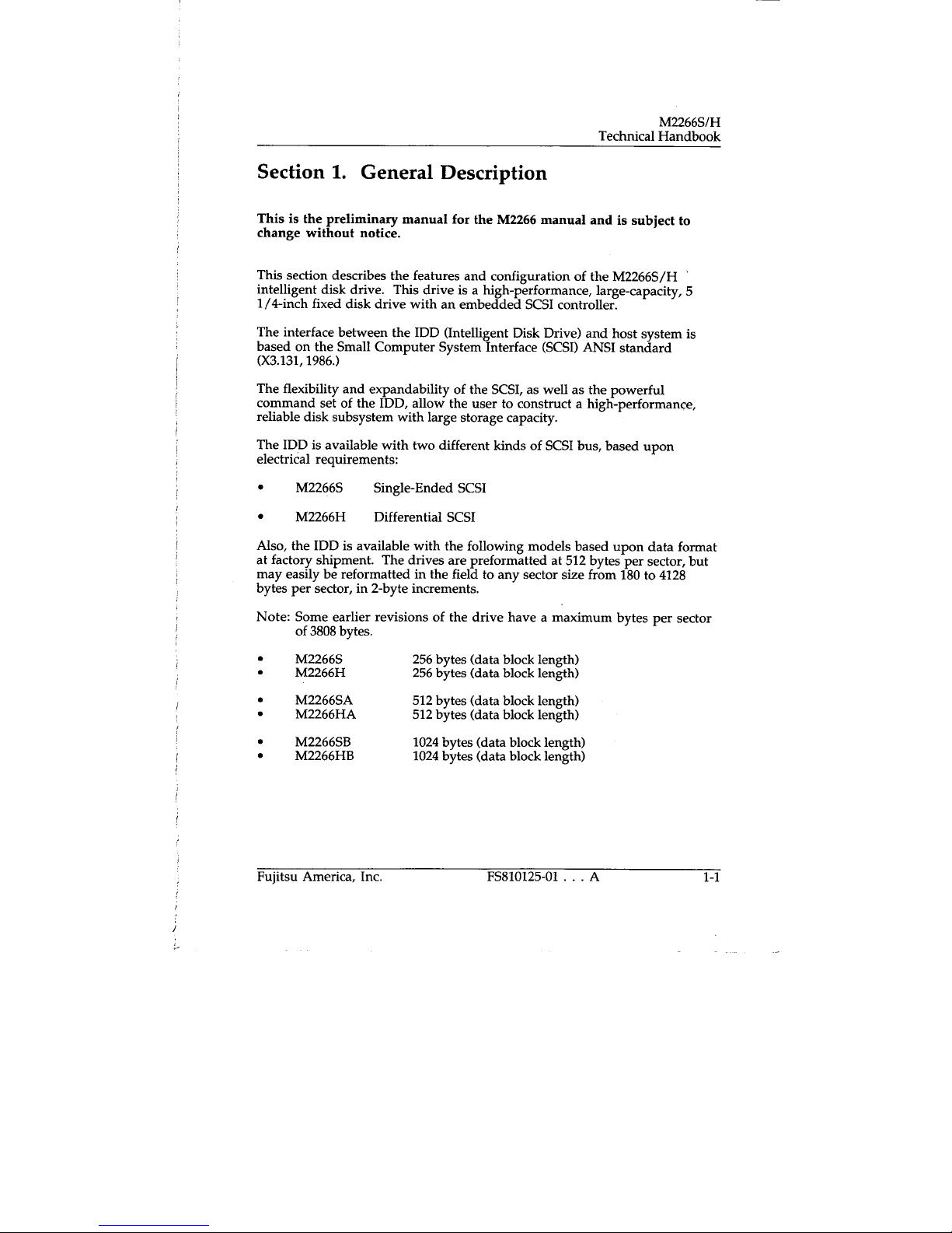
Section 1. General Description
This
is the preliminary manual for the M2266 manual and is subject to
change without notice.
This section describes the features and configuration of the M2266S/H
intelligent disk drive. This drive is a high-performance, large-capacity, 5
1/4-inch fixed disk drive with an embedded SCSI controller.
The interface between the IDD (Intelligent Disk Drive) and host system is
based on the Small Computer System Interface (SCSI) ANSI standard
(X3.131, 1986.)
The flexibility and expandability of the SCSI, as well as the powerful
command set of the IDD, allow the user to construct a high-performance,
reliable disk subsystem with large storage capacity.
The IDD is available with two different kinds of SCSI bus, based upon
electrical requirements:
M2266S
Single-Ended SCSI
•
M2266H
Also, the IDD is available with the following models based upon data format
at factory shipment. The drives are preformatted at 512 bytes per sector, but
may easily be reformatted in the field to any sector size from 180 to 4128
bytes per sector, in 2-byte increments.
Differential SCSI
Note: Some earlier revisions of the drive have a maximum bytes per sector
of 3808 bytes.
M2266S
M2266H
M2266SA
M2266HA
M2266SB
M2266HB
Fujitsu America, Inc.
256 bytes (data block length)
256 bytes (data block length)
512 bytes (data block length)
512 bytes (data block length)
1024 bytes (data block length)
1024 bytes (data block length)
FS810125-01 . . . A
1-1
Page 12
M2266S1H
Technical Handbook
Standard Features
Compactness
Since the SCSI controller circuit is inside the IDD PCA in the standard 5 1/4-
inch fixed disk drive form factor, the IDD is extremely compact. The IDD
can be connected directly to the SCSI bus of the host system.
SCSI/CCS Standard
The IDD provides not only SCSI basic functions but also the following
features:
•
Arbitration
•
Disconnection/Reselection
Data Bus Parity
•
Command set which meets the logical specification of the SCSI CCS
•
(Common Command Set for Direct Access Device) Requirements
(Rev. 4B).
The SCSI commands can manipulate data through logical block addressing
regardless of the physical characteristics of the disk drive. This allows
software to accommodate future expansion of system functions.
High-Speed Data Transfer
The data transfer rate on the SCSI bus is 2.00MB/s maximum, in
asynchronous mode and 4.8 MB/s maximum in synchronous mode. Such a
high data transfer rate on the SCSI bus can be useful with the large capacity
buffer in the IDD.
Notes:
1.
2.
1-2
The maximum data transfer rate in asynchronous mode may be
limited by the response time of the initiator and by the SCSI bus
length.
The maximum data transfer rate in synchronous mode on the
single-ended SCSI bus may be limited by the cable length and
transmission characteristics of the SCSI bus.
FS810125-01 . . . A
Fujitsu America, Inc.
Page 13

Technical Handbook
M2266S1 H
Continuous Block Processing
The addressing method of data blocks is logical block address. The initiator
can access data by specifying the block number in a logically continuous data
space without regard to the physical structure of the track or of cylinder
boundaries.
The continuous processing of up to 64K blocks in a command can be
achieved, aid the IDD can perform continuous read/write operations when
processing data blocks across track or cylinder boundaries.
256KB Data Buffer
Data is transferred between the SCSI bus and the disk media through the
embedded 256KB data buffer in the IDD.
Since the initiator can control the disconnect/ reconnect timing on the SCSI
bus by specifying the condition of stored data to the data buffer or empty
condition of the data buffer, the initiator can perform the effective
input/output operations by utilizing the high data-transfer capability of the
SCSI bus, regardless of the actual data transfer rate of the disk drive.
Read-Ahead Cache Feature
After executing the READ command, the IDD reads automatically and stores
(prefetches) the subsequent data blocks into the data buffer (Read-Ahead
caching.) This function may be programmed to prefetch data in amounts
from one sector's worth to 256 Kbytes of data.
The high-speed sequential data access can be achieved by transferring the
data from the data buffer without reaccessing the disk in case the subsequent
command requests the prefetched data blocks.
Command Stack Feature
The command stack feature of the IDD corresponds to up to seven initiators.
Therefore, the IDD can accept and stack the input/output command issued
by another initiator even if the IDD is executing another command. The
stacked command is retrieved and executed in stacked order after the
present command has completed execution.
Reserve and Release Functions
The IDD can be accessed exclusively in the multi-host or multi-initiator
environment by using the reserve and release functions.
Fujitsu America, Inc.
FS810125-01 . . . A
1-3
Page 14

M2266S/H
Technical Handbook
Error Recovery
The IDD can try to recover from errors in the SCSI bus or the disk drive
using its powerful retry processing. If a recoverable data check occurs, error-
free data can be transferred to the initiator after being corrected in the data
buffer. The initiator software is released from the complicated error
recovery processing by these error recovery functions of the IDD.
Automatic Alternate Block Reassignment
If a defective data block is detected during read or write, the IDD can
automatically reassign its alternate data block.
Programmable Data Block Length
Data can be accessed with a fixed block-length unit. Data block length is
programmable, and can be set during formatting to the most suitable length,
from 180 to 4,128 bytes, with a 2-byte boundary.
Defective Block Slipping
A logical data block can be reallocated in a physical sequence by slipping the
defective data block during formatting. This results in high speed
contiguous data-block processing without a revolution delay due to a
defective data block.
High-Speed Positioning
A rotary voice coil motor achieves fast positioning.
Large Capacity
The unformatted capacity is 1266 MB. Typically, at 512 bytes per sector the
formatted capacity is 1079 MB. A disk subsystem with large capacity can be
constructed that uses space efficiently.
Start/Stop of Spindle Motor
Using the SCSI command, the host system can start and stop the spindle
motor.
Diagnosis
The IDD has a diagnostic capability that checks internal controller functions
and drive operations to facilitate testing and repair.
1-4
FS810125-01 . . . A
Fujitsu America, Inc.
Page 15
Technical Handbook
M2266S/H
Low Power Consumption
By using highly-integrated LSI components, the power consumption of the
IDD is very low, enabling use of the unit in a wide range of ambient
temperatures between 5°C and 45°C.
Low Noise and Low Vibration
The IDD is quiet, running at approximately 45 dB (A-scale weighting) even
during seek, making it ideal for office use. The IDD has rubber vibration
isolators, which minimize the transfer of vibration.
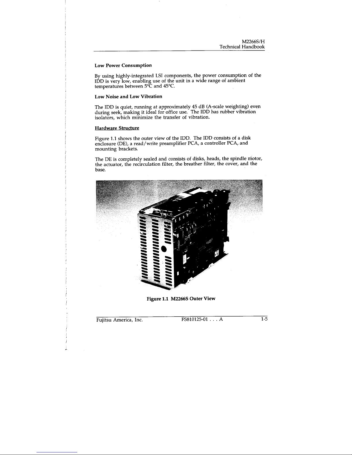
Hardware Structure
Figure 1.1 shows the outer view of the IDD. The IDD consists of a disk
enclosure (DE), a read/write preamplifier PCA, a controller PCA, and
mounting brackets.
The DE is completely sealed and consists of disks, heads, the spindle motor,
the actuator, the recirculation filter, the breather filter, the cover, and the
base.
Fujitsu America, Inc.
Figure 1.1 M2266S Outer View
FS810125-01 . . . A
1-5
Page 16

M2266S/H
Technical Handbook
Disks
The Winchester-type disks have an outer diameter of 130 mm (5.12 inches)
and an inner diameter of 40 mm (1.57 inches). The disks are good for at least
10,000 contact starts and stops.
The IDD uses the following number of disks:
M2266: 8 disks
Heads
The Whitney-type CSS (contact start/stop) heads are in contact with the
disks when the disks are not rotating, and automatically float when the
rotation reaches nominal speed.
Spindle Motor
The disks are turned by a direct-drive DC motor. The motor turns at 3600
rpm, ±0.2%. This precision is achieved through a feedback circuit which
includes Hall-effect elements mounted in the motor assembly.
Actuator
The actuator, which uses a rotary voice coil motor (VCM), consumes little
power and generates little heat. The head assembly on the tip of the actuator
arm is controlled by electrical feedback from servo information read-out
through the servo head.
Servo information is used as a control signal activating the actuator. It is
used as track crossing information in positioning, and track following
information during data write/read. The actuator positions heads on the
innermost landing zones over the disk when the power is off or the spindle
motor is stopped.
Air Circulation
The heads, disks, and actuator are sealed inside a disk enclosure (DE) to keep
out dust and other pollutants.
The DE has a closed-loop air recirculation system. Using the movement of
the rotating disks, air is continuously cycled through a filter. This filter will
1-6
F5810125-01 . . . A
Fujitsu America, Inc.
Page 17
Technical Handbook
M2266S/H
trap any dust generated inside the enclosure and keep the air inside the DE
contaminant-free. To prevent negative pressure in the vicinity of the
spindle when the disks begin rotating, a breather filter is attached. The
breather filter also equalizes the internal air pressure with the atmospheric
pressure due to surrounding temperature changes.
Read/Write Circuit
The read/write circuit uses LSIs and head ICs to prevent errors caused by
external noise, thus increasing reliability.
Controller Circuit
The controller circuit uses LSIs to increase reliability and uses a high-speed
Micro-Processing Unit (MPU) to increase the performance of the SCSI
controller.
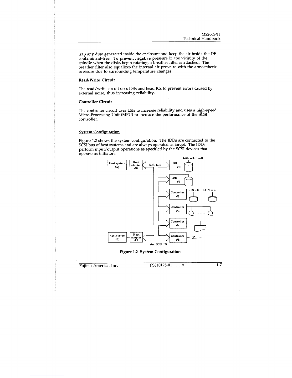
System Configuration
Figure 1.2 shows the system configuration. The IDDs are connected to the
SCSI bus of host systems and are always operated as target. The IDDs
perform input/output operations as specified by the SCSI devices that
operate as initiators.
LUN =
A
0 (hoed)
1-7
Host system
(A)
lost system - aHost
I
-
(B)
adapter
Figure
Fujitsu America, Inc.
Host
#6
( SCSI bus
I DI)
IDD
>
Controller LUN=0 LUN=n
Controller
>
Controller
N,
/ #4
dapter
#7
(
System Configuration
1.2
SCSI 10
FS810125-01
Controlle
)
...
#0
#1
#2
#3
#5
Page 18

M2266S/H
Technical Handbook
SCSI Bus Configuration
Up to eight SCSI devices can be connected to the SCSI bus, with any
combination of the SCSI devices operating as initiators and operating as
targets.
For example, the system can be configured as a multi-host system on which
multiple host computers that operate as initiators are connected through the
SCSI bus.
Using the disconnect/reconnect function, concurrent input/output
processing is possible on multi-SCSI devices.
Peripheral Device Addressing
Each SCSI device on the bus has its own unique address (the SCSI ID
number shown in Figure 1.2). For input/output operations, a peripheral
device attached to the SCSI bus and operating as the target is addressed as the
logical unit. A unique address or logical unit number (LUN) is assigned to
each logical unit.
The initiator selects one SCSI device by specifying the SCSI ID, and then
specifies the LUN to select the peripheral device for input/output
operations.
When the IDD is constructed so that the whole volume of disk drives is a
single logical unit, the selectable SCSI ID and LUN are as follows:
•
SCSI ID: Jumper selectable from 0 to 7
•
LUN: 0 (fixed)
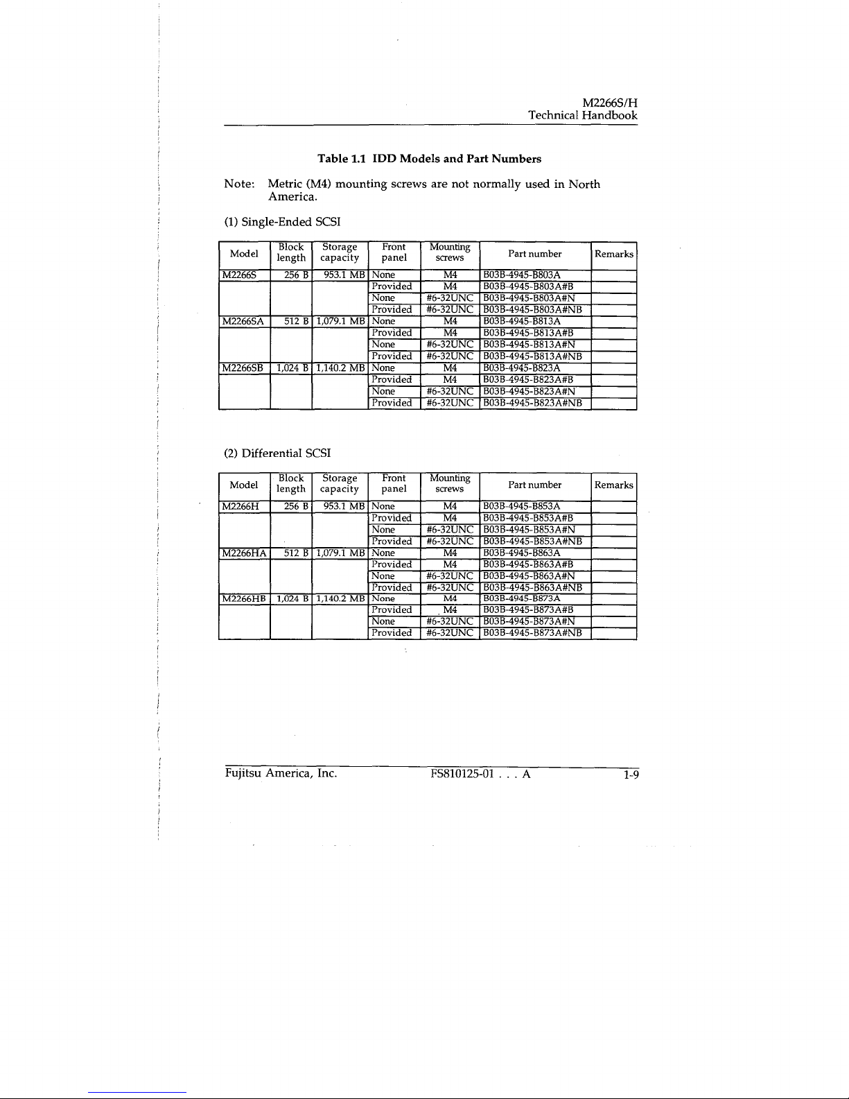
Model/Part Number Cross References
Each model has a different data format, front panel, and mounting-screw
type. Table 1.1 shows the IDD model names and part numbers. To change
the data format, reinitialize the drive on your system.
1-8
FS810125-01
...
A
Fujitsu America, Inc.
Page 19
Technical Handbook
M2266S/H
Table 1.1 IDD Models and Part Numbers
Note: Metric (M4) mounting screws are not normally used in North
America.
Single-Ended SCSI
(1)
Model
M22665
M2266SA
M2266SB
(2)
Model
M2266H
M2266HA
M2266HB
Block
length
1,024 B
Differential SCSI
Block
length
1,024 B
256 B
512 B
256 B
512 B
Storage
capacity
953.1 MB
1,079.1 MB
1,140.2 MB
Storage
capacity
953.1 MB
1,079.1 MB
1,140.2 MB
Front
panel
None
Provided
None
Provided
None
Provided
None
Provided
None
Provided
None
Provided
Front
panel
None
Provided
None
Provided
None
Provided
None
Provided
None
Provided
None
Provided
Mounting
screws
M4
M4
#6-32UNC
#6-32UNC
M4
M4
#6-32UNC
#6-32UNC
M4
M4
#6-32UNC
#6-32UNC
Mounting
screws
M4
M4
#6-32UNC
#6-32UNC
M4
M4
#6-32UNC
#6-32UNC
M4
M4
#6-32UNC
#6-32UNC
Part number
B03B-4945-B803A
B03B-4945-B803A#B
B03B-4945-U803A#N
B03B-4945-B803A#NB
B03B-4945-B813A
B03B-4945-B813A#B
B03B-4945-B813A#N
B03B-4945-B813A#NB
B03B-4945-B823A
B03B-4945-B823A#B
B03B-4945-B823A#N
B03B-4945-B823A#NB
Part number
B03B-4945-B853A
B03B-4945-B853A#B
B03B-4945-B853A#N
B03B-4945-B853A#NB
B03B-4945-B863A
B03B-4945-B863A#B
B03B-4945-B863A#N
B03B-4945-B863A#NB
B03B-4945-B873A
B03B-4945-B873A#B
B03B-4945-B873A#N
B03B-4945-B873A#NB
Remarks
Remarks
Fujitsu America, Inc.
FS810125-01 . . . A
1-9
Page 20

M2266S/H
Technical Handbook
1-10
FS810125-01
A
Fujitsu America, Inc.
Page 21
Technical Handbook
M2266S/H
Section 2. Installation Requirements
Introduction
Installation of the M2266S/H disk drive is a two-part process:
•
Mechanical and electrical installation of the hardware
•
Performance of the software procedures needed to bring the device to
operational readiness.
This section contains information on the requirements for hardware
installation, including the physical dimensions that assist in mounting the
device, the cabling schemes, and information on how to set the jumpers.
For specific information on installing the drives, see section 3. For
information on software installation of the drive in a Personal Computer
environment, see section 4.
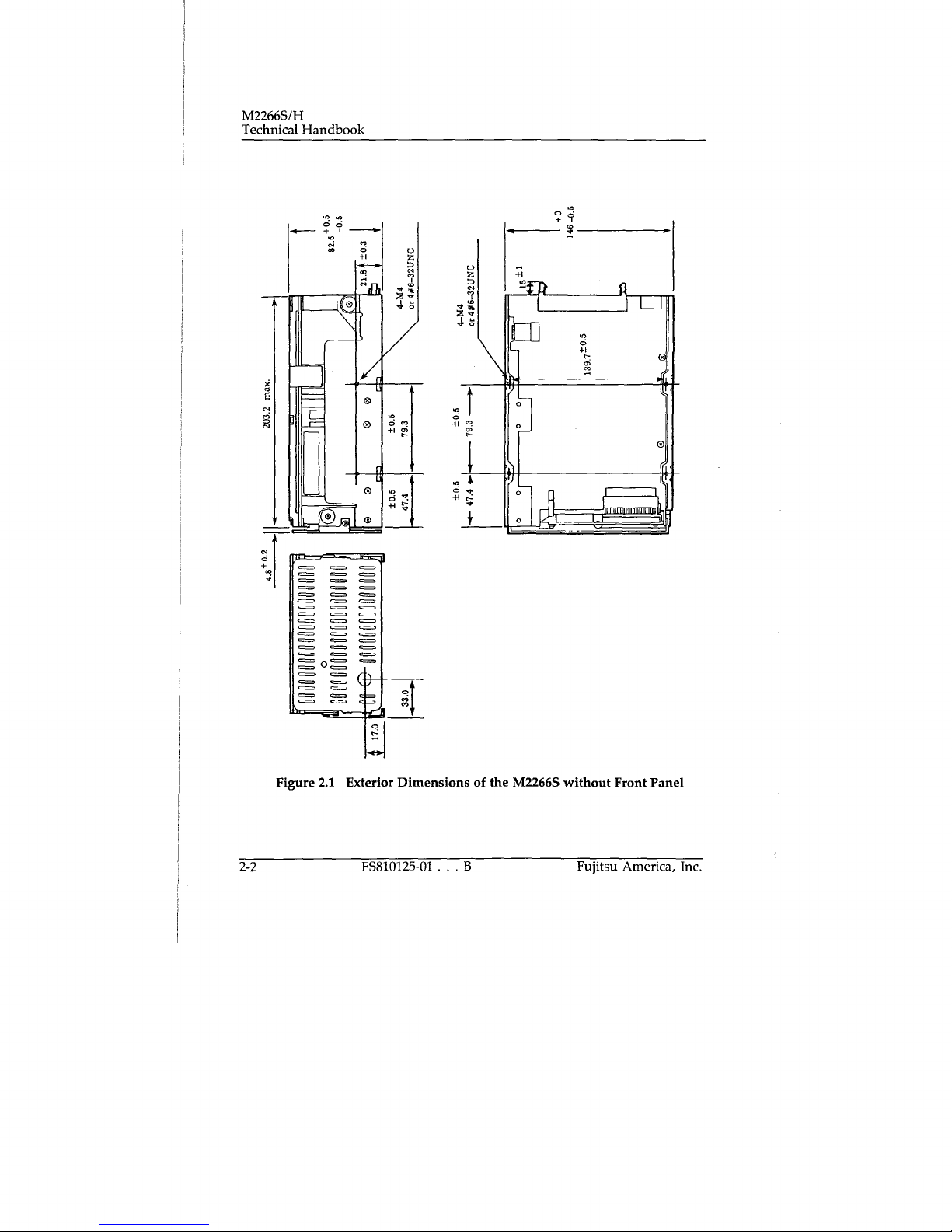
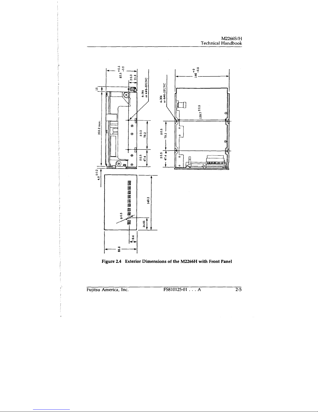
Outer Dimensions
Figures 2.1 to 2.4 show the exterior dimensions of the IDD and the positions
of the holes for the IDD mounting screws.
Notes:
1.
Dimensions are in mm.
2.
The depth does not include the dimension of the hook for mounting
the cable on the interface connector.
Fujitsu America, Inc.
FS810125-01 . . . A
2-1
Page 22
M2266S/H
Technical Handbook
IIIIIIIIfIIIIIIIIIIIINII l
Figure 2.1 Exterior Dimensions of the M2266S without Front Panel
2-2
FS810125-01 B
Fujitsu America, Inc.
Page 23
Technical Handbook
M2266S/H
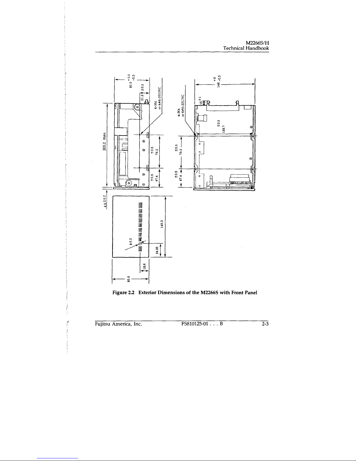
Figure 2.2 Exterior Dimensions of the M2266S with Front Panel
Fujitsu America, Inc.
FS810125-01 . B
2-3
Page 24
M2266S/H
Technical Handbook
U
z
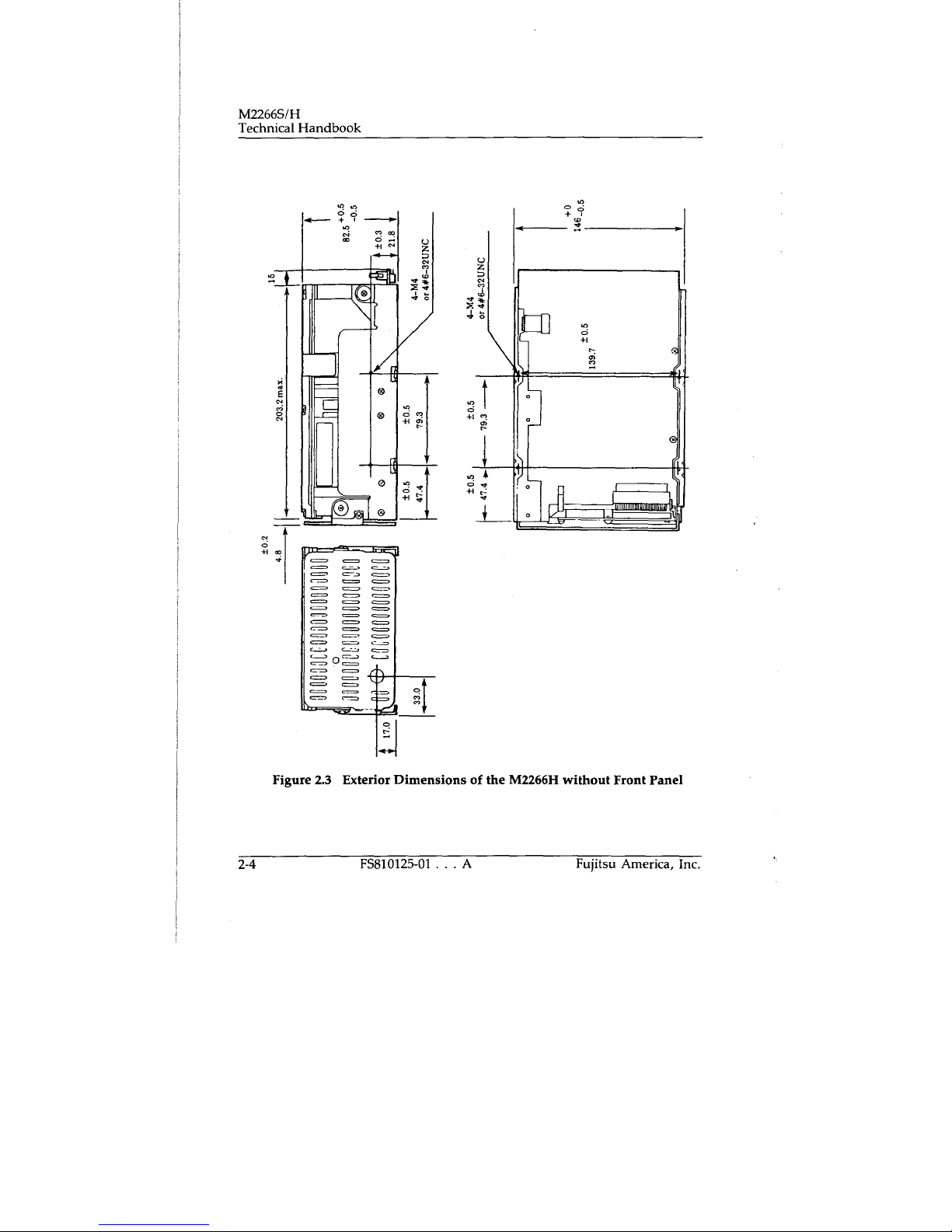
Figure 2.3 Extenor Dimensions of the M2266H without Front Panel
2-4
FS810125-01
A
Fujitsu America, Inc.
Page 25
Oh
ON
Ito
fill
lID
ItOh
Technical Handbook
M2266S/H
gI
IR
Figure 2.4 Exterior Dimensions of the M2266H with Front Panel
Fujitsu America, Inc.
FS810125-01 A
2-5
Page 26

M2266S/H
Technical Handbook
Mounting
Figure 2.5 shows the permissible orientations of the IDD. The tolerance of
the angle is ±5° from the horizontal plane.
Direction
of gravity
(n) Horizontal
(b) Vertical
(ci Vortical
Figure 2.5 IDD Orientation
Mounting Frame Structure
The disk enclosure (DE) of the IDD serves as a signal ground (SC) and is
insulated from the mounting frame. As this insulation is maintained after
the IDD is mounted in the system, the following precautions must be
followed:
Note:
Generally, SC and FG (frame ground) are connected at one point in the
system enclosure. To maintain insulation when mounting the IDD:
Use the frame with an embossed structure to avoid contact between
(a)
the DE base and FG.
As shown in Figure 2.6, the inward projection of the screw from the
(b)
IDD frame wall at the corner must be 4 mm or less.
4 or lens
2-6
4 or lens
(Unit mm)
Figure 2.6 Mounting Frame Structure
FS810125-01 . . . A
Fujitsu America, Inc.
Page 27
Technical Handbook
M2266S/H
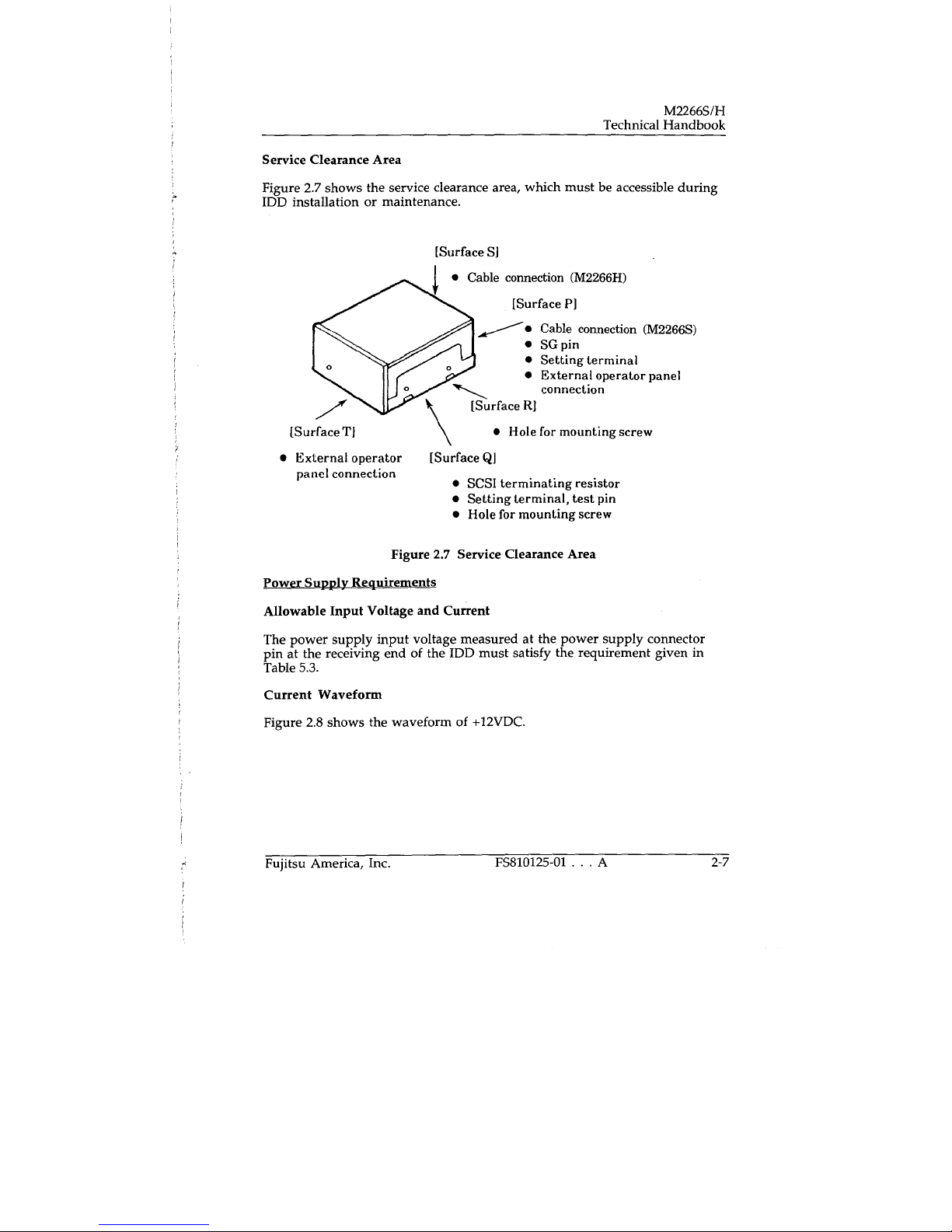
Service Clearance Area
Figure 2.7 shows the service clearance area, which must be accessible during
IDD installation or maintenance.
[Surface SI
•
Cable connection (M2266H)
[Surface P1
Cable connection (M2266S)
•
SG pin
•
Setting terminal
•
External operator panel
connection
[Surface RI
•
[Surface TI
•
External operator [Surface Qi
panel connection
• SCSI terminating resistor
•
•
Hole for mounting screw
Setting terminal, test pin
Hole for mounting screw
Figure 2.7 Service Clearance Area
Power Supply Requirements
Allowable Input Voltage and Current
The power supply input voltage measured at the power supply connector
pin at the receiving end of the IDD must satisfy the requirement given in
Table 5.3.
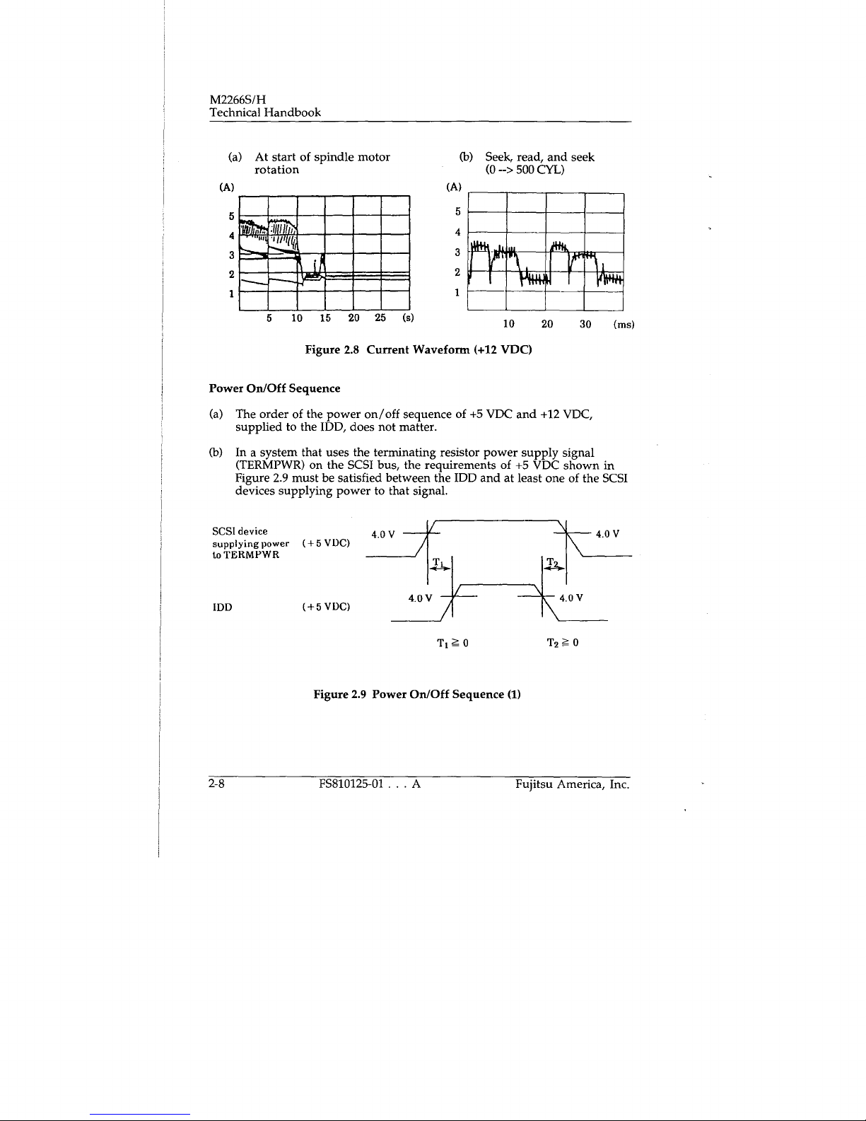
Current Waveform
Figure 2.8 shows the waveform of +I2VDC.
Fujitsu America, Inc.
FS810125-01 ... A
2-7
Page 28
M2266S/H
Technical Handbook
At start of spindle motor
(a)
rotation
(A)
5
4
'Iu
•
1
3
2
I
5 10 15 20 25 (s)
Seek, read, and seek
(b)
(0--> 500 CYL)
(A)
5
4
3
2
?%M~~
1
10
20
44
30 (ms)
Figure 2.8 Current Waveform (+12 VDC)
Power On/Off Sequence
The order of the power on/off sequence of +5 VDC and +12 VDC,
(a)
supplied to the IDD, does not matter.
In a system that uses the terminating resistor power supply signal
(b)
(TERMPWR) on the SCSI bus, the requirements of +5 VDC shown in
Figure 2.9 must be satisfied between the IDD and at least one of the SCSI
devices supplying power to that signal.
SCSI device
supplying power (+ 5 VDC)
TERMPWR
to
4.0 V
IDD
2-8
(+5 VDC)
4.0 V
/
Tj0
\4 0 V
T20
Figure 2.9 Power On/Off Sequence (1)
FS810125-01
. . .
A
Fujitsu America, Inc.
Page 29
Technical Handbook
M2266S/H
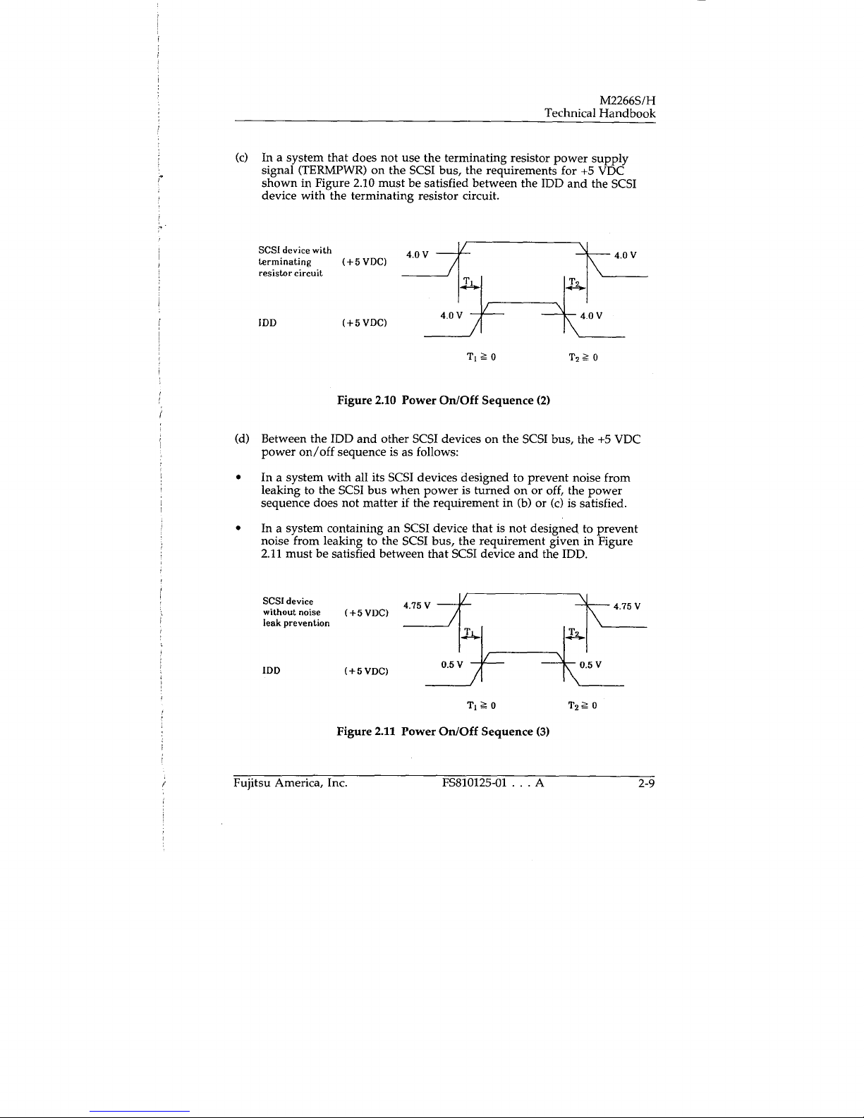
In a system that does not use the terminating resistor power supply
(c)
signal (TERMPWR) on the SCSI bus, the requirements for +5 VDC
shown in Figure 2.10 must be satisfied between the IDD and the SCSI
device with the terminating resistor circuit.
SCSI
device with
terminating
resistor circuit
IDD
(+5 VDC)
(+5VDC)
4.OV
4.0
V
T10
T20
4.0 V
40V
Figure 2.10 Power On/Off Sequence (2)
Between the IDD and other SCSI devices on the SCSI bus, the +5 VDC
(d)
power on/off sequence is as follows:
•
In a system with all its SCSI devices designed to prevent noise from
leaking to the SCSI bus when power is turned on or off, the power
sequence does not matter if the requirement in (b) or (c) is satisfied.
•
In a system containing an SCSI device that is not designed, to prevent
noise from leaking to the SCSI bus, the requirement given in Figure
2.11 must be satisfied between that SCSI device and the IDD.
SCSI device
without noise
leak prevention
IDD
(+5 VDC)
(+SVDC)
4.75 V
0.5V
T10
4.75 V
05V
T20
Figure 2.11 Power On/Off Sequence (3)
Fujitsu America, Inc.
FS810125-01 . . . A
2-9
Page 30

M2266S/H
Technical Handbook
Sequential Starting of Spindle Motors
After power is turned on to the IDD, a large amount of current flows in the
+12 VDC line as the spindle motor rotation starts. Therefore, if more than
one IDD is used, the spindle motors should be started sequentially using one
of the following procedures to prevent overload of the power supply unit.
For information on setting spindle motor start control mode, see Setting
Terminals" in section 3.
Issue START commands at 20-second intervals to start the spindle
a.
motors.
b.
Turn on the +12 VDC power in the power supply unit at 20-second
intervals to start the spindle motors sequentially.
Power Supply to SCSI Terminating Resistor
If power for the terminating resistor is supplied from the IDD to other SCSI
devices through the SCSI bus, the current-carrying capacity of the +5 VDC
power supply line to the IDD must be designed with consideration given to
an increase of up to 900 mA for the M2266S or up to 600
mA
for the
M2266H.
The method of supplying power to the terminating resistor is shown in
Figure 2.12.
2-10
FS810125-01 . . . A
Fujitsu America, Inc.
Page 31

M2266S/H
Technical Handbook
Section 4. Software Installation
Introduction
Due to the vast array of computer types, controllers, device configurations,
and software utilities in use within small business systems, it is impossible
to give specific installation instructions for each computer type in which the
drive may be installed. There is no generic installation description that
would apply in all cases.
Instead, this section presents basic principles for installing the M2266S/H
disk drive into the most frequently used system: an IBM Personal
Computer or PC-clone, using the PC DOS or MS DOS operating system.
Preparation of the Hard Disk for DOS Applications
Definition of Drive Type
First define the hard drive as "zero",or, "not installed".
Basic Steps for Software Installation
Software installation on the M2266S/H drive involves partitioning, and
high-level formatting. It requires the following steps:
Step 1: Boot DOS, and then run the DEBUG program. At the DEBUG
prompt (" — "), type g=c800:5 to access the BIOS-level formatter.
(Note: The manufacturer of the controller may specify a different
segment and offset location to access the low-level formatter, or
may provide standalone installation software.)
Drive Partitioning
With a DOS version of 3.3 or lower, the maximum drive capacity is 32 MB.
Therefore, multiple drive partitions (C:, D:, E:, . . Z:) of 32 MB or less must
be created. (See step 3 below.) Definition of larger partition size requires
either DOS 4.0x or a third-party software package such as Disk Manager®
from Ontrack Systems, Inc.
Fujitsu America, Inc.
FS810125-01 . . . A
4-1
Page 32

M2266S/H
Technical Handbook
Step 2: Run the software to create the partitions required by your unique
configuration. (This software is either the FDISK program or one
of the third-party software packages mentioned above.) Then boot
the system again to save the partitions.
Step 3: To perform high-level (or DOS-level) formatting of the partitions,
use the DOS FORMAT command or follow the on-screen
instructions for a third-party software package. If using the
FORMAT command, enter it at the A: prompt as follows:
FORMAT d:/s
d
where
drive. The
is the drive letter (typically C) assigned by DOS to the hard
Is
flag automatically copies the system files required to
boot the system from the hard drive.
The flow chart on the following page summarizes the steps for partitioning
the drive and preparing the drive to receive data.
4-2
FS810125-01 . . . A
Fujitsu America, Inc.
Page 33

Technical Handbook
Partitioning and High-Level Formatting
Start
I
Partition
Hard disk
M2266S/H
Use Compaq
tX)S 3.31 or
MS/PC DOS
4.01 or
Greater
I
(Run Fdisk*)
Use DOS
3.3 Run
Fdjsk
Create
Partitions
Reboot the
System to write
the partition
table on the
disk
Format the
Partitions. Use
/5 Option on
Boot Partition.
Transfer System
files on Boot
Drive or
Partition
Use Host
Adapter
Mfr's Standalone
Software or
Disk Manager
4.0 and Above.
Create
Partitions
Scan or
Verify the
Partitions.
Fujitsu America, Inc.
I
/ Hard
Disk'\
Prepa ation
Complete.
FS810125-01 A
4-3
Page 34

M2266S/H
Technical Handbook
4-4
FS810125-01 . . . A
Fujitsu America, Inc.
Page 35

Technical Handbook
Section 5. Specifications
This section describes the functional and environmental specifications of
the M2266S/H disk drives.
Table 5.1 Drive Functional Specifications (1 of 2)
M2266S/H
Unformatted capacity of the
drive (*1)
Number of disks
Number of heads
(read/write + servo)
Number of cylinders
(user + CE + SA) (*2)
Unformatted Capacity / Track
(*1)
Rotational Speed
Average Latency Time
Positioning Time
Start/Stop Time
(*3)
Recording Code
Recording Density
Track Density
Dimension
(W x H x D) (*4)
Items
Minimum
Average
Maximum
Start Time
Stop Time
M2266S
M2266H
Specifications
M2266
1266MB
8
15+1
1,658 + 1 + 2
50,910 Bytes
3,600 rpm 0.2%
8.3 ms
4 ms
14.5 ms
30 ins
20 seconds, maximum
15 seconds, maximum
1/7 RLL
46,635 BPI
1,634 TPI
5.7 in (146 mm) x 3.3 in. (83 mm) x 8.0 in (203 mm)
Front Protector Installed: 5.7 in x 3.3 in x 8.2 in
Front Panel Installed: 5.9 in x 3.4 in x 8.2 in
5.7 in (146 mm) x 3.3 in. (83 mm) x 8.6 in. (218mm)
Front Protector Installed: 5.7 in. x 3.3 in. x 8.8 in.
Front Panel Installed: 5.9 in x 3.4 in. x 8.8 in.
Fujitsu America, Inc.
FS810125-01 . . . B
5-1
Page 36

C
S
TEMPWR
SIGNAL
Setting terminal (CNH4)
CD
FUSE -.
(Inserted in a socket)
3
Termi-
resistor
Technical Handbook
M2266S/H
+5VDC
nating
circuit
IDD
TERMPWR
Power supply to terminal resistor circuit on IDD
Power is supplied from both IDD and
Power is supplied from 100 only
Power is supplied from
(100
power
supply is not used)
The
setting mode
(TERMPWR
TERMPWR
TERMPWR
TERMPWR
pin only
pin is also supplied with power from IDD
pin (°)
Pin is not used)
- GND
Setting erminal
(CNH4)
1-2
Strap Strap
Open
Strap
3-4
Strap
Open
Figure 2.12 Supplying Power to the Terminating Resistor
Connectors
Connectors and terminals for connection to the outside are installed on the
IDD. Their positions are shown in Figures 2.13 and 2.14.
•
Power supply connector
•
SCSI connector
•
SC (signal ground) connector
•
Connector for external operator panel
Fujitsu America, Inc.
FS810125-01 . . . A
2-11
Page 37

M2266S/H
Technical Handbook
Power supply
connector
SO
terminal
SCSI
ccnnector(CNI)
Setting terminal (CN9)
(External operator panel connector)
Figure 2.13 Positions of M2266S Connectors
Read/write
preamplifier
PCA
Read/write
preamplifier
connector
External operator
panel connector
(CNT)
VCM
connector
Control printed
circuit board
Spindle motor
connector
Setting terminal ICN3(
(External operator panel connector)
axoenbly(PCA)
2-12
Setting Ler.oimn1lCN9)
(External operator panel connector)
Setting tocminnllCN3
(External operator panel connector)
Figure 2.14 Positions of M2266H Connectors
A
FS810125-01
Fujitsu America, Inc.
Page 38

Technical Handbook
M2266S1H
Power Supply Connector
Figure 2.15 shows the shape and pin configuration of the DC power supply
connector.
1M226xSI
01
+I2VDC
+ 12 VUC Return (GND)
+5 VDC Return (GND)
3
+5VDC
(M226x11 J
D
0 3
2.15 Power Supply Connector
Figure
/
SCSI Connector
The connector for the SCSI bus is an unshielded standard connector which
has two rows of 25 pins spaced 2.54 mm (0.1 inch) apart. Figure 2.16 shows
several views of the connector and gives the physical specifications. See
Table 6.3 for the signal assignments on the connector for the single-ended
type SCSI bus (M2266S) and the differential-type bus (M2266H).
IMZZS,SI
0
Symbol
DI
D2
D3
D4
rrin
2.54
2.54
4.19+102
-0.25
6.09
Figure 2.16 SCSI Connector
Fujitsu America, Inc.
1M226.IIi
I
Inches
0.1
0.1
0.165+0.04
-0.01
0.24
FS810125-01 . . . A
Remarks
2-13
Page 39

M2266S/H
Technical Handbook
SG Terminal
For DC ground, an SG terminal (Fastin-Faston tab) is mounted as shown in
Figure 2.17.
Controller PCA
SCSI connector
Note: This figure shows the M22668
Figure 2.17 SG Terminal
Connectors for External Operator Panel
Two types of connectors for the external operator panel are provided on the
IDD as shown in Figure 2.18. They allow connection of an external write
protect switch, an LED on the front panel, and an SCSI ID setting switch. For
the recommended circuit of the external operator panel, see Figure 2.21.
2-14
FS810125-01 . . . A
Fujitsu America, Inc.
Page 40

Pin 13
2.54 nun
2.54 mm
Pin I
(CN9)
Pa2 Pin
,D
(CN3
\-
2.54 mm
Technical Handbook
M2266S/H
CN3/CN9
Pin 13
Pin
Pin 14
2.54mm
2.54 mm
Note: This figure shows the M22868s.
CN7
Signal Signal
01
+DIAG
03
(Reserved)
05
—RAC
07
—STM
09
—104
Ii
—11)2
13
—101
In M2266H, the setting terminal
(CNR4) exists between CN9 and CN3,
but pin assignments of CN9 and CN3
GNU
GND
GNU
GNU
GNU
GNU
GNU
are the same as M2266Ss.
Pin
01
03
Signal
LED (V)
—WPR
Signal
WPR(G)
—LED
Pin
02
04
06
08
10
12
14
Pin
02
04
Pin 1
Pin 3
Pin 2
Pin 4
Figure 2.18 External Operator Panel Connector
Fujitsu America, Inc.
Note: Pins 04 to 10 are connected to the cable
connector for internal connection.
Only pins 01 to 04 are used for
connection of the operator panel.
2.54 aim
FS810125-01
A
2-15
Page 41

M2266S/H
Technical Handbook
Notes:
I. Some signals are assigned on both pins CN3 and CN9.
When no external operator panel is connected to the IDD, CN3 and
2.
CN9 are used for setting the terminal of the SCSI ID, etc. (see Setting
Terminals' in section 3) When the IDD is shipped from the factory,
the short plugs are mounted between all even numbered and odd
numbered pins of CN9 and no short plug is mounted on CN3.
When the external operator panel is connected to CN3 or CN9, pay
3.
attention to the following items.
CN3 and CN9 are physically interchangeable. The external
•
operator panel can be connected to either one.
When the external operator panel is connected to CN9, all short
•
plugs on CN9 must be removed. However, pins on CN3
corresponding to the signal set on the external operator panel
must be opened. When there is a signal not set on the external
operator panel, the state of that signal must be set on CN3 using
the short plug. The removed short plug from CN9 can be used for
setting the state.
When the external operator panel is connected to CN3, the short
•
plug on CN9 corresponding to the signal set on the external
operator panel must be removed. When there is a signal not set
on the external operator panel, the state of that signal must be set
on CN9 using the short plug.
Connection Requirements
This section discusses the connections required when installing the drive.
SCSI Cable
All SCSI devices on one bus are daisy-chained with an SCSI cable. A
terminating resistor must be mounted in the SCSI device at each end of the
SCSI cable.
2-16
FS810125-0I . . . A
Fujitsu America, Inc.
Page 42

Technical Handbook
M2266S1H
Since an SCSI terminating resistor module is mounted in the IDD on
shipment, it must be removed when the IDD is not connected at either end
of the SCSI cable. Also, a method for supplying power to the terminating
resistor must be selected with the setting terminal on the IDD. For further
details, see "Setting Terminals" in section 3.
The maximum number of SCSI devices that can be connected to the SCSI
bus is 8, including the host adaptor, IDD, and other SCSI equipment.
The connector socket for the SCSI cable must be an unshielded 50-contact
socket which has two rows of 25 contacts spaced at 2.54 mm (0.1 inch) apart.
It should also have a key way to prevent insertion in the wrong direction
(bump type connector). (See Figure 2.16).
Pi. 50\
i—Cl
Pi.
C8—
C3
I
.Pial
lu
000000 JO 00000
L19
0 0 0 0 0 0 0 0 0 0 0 0 0 0 0 0 0 0 0 0 0 0J
"Pin2
Synhol
nn
CI
2.540
CS
60.960
2,540
C3
Ca
3.302
CS
32.385
68.072
C6
Cl
6,096
7.620
CO
Notn: The Lolnroncnin ± 0.127 mm (0.805 inch) onlnnn oLhnrc inn npnciflnd,
Figure 2.19 SCSI Cable Connector
Fujitsu America, Inc.
Li
—I 1—
C4
CS
nhllinnhlu
R
CO
CO
Inch
0.100
2.400
0.100
0.130
1.275
2.680
0.240
0.300
Mon.
FS810125-01 . . . A
00000000
Remark
Pio49._
P50"
rn
ci
I
{
2-17
Page 43

M2266S/H
Technical Handbook
The maximum length of the SCSI cable is as follows. If more than one SCSI
device is connected, the total cable length must not exceed the following:
•
6 m for single-ended type SCSI
25 m for differential type SCSI
•
The use of a 25-pair twisted cable satisfying the following requirements is
recommended.
Single-Ended Type
Conductor Size: 28 AWG (American Wire Guage) or bigger
Characteristics impedance: 100 to 132
Differential Type
Conductor Size: 28 AWG or bigger
Characteristic impedance: 100 to 122 0
Each pair of wires in the 25-pair twisted cable must be connected to pins n
and n+1 (where n is an odd number) on the interface connector. Cables
having an identical impedance must be used on the same SCSI bus to reduce
signal reflection and maintain transmission characteristics.
When an SCSI device is connected to the SCSI cable (except at either end of
the cable), connection to the SCSI connector must be at a branch point of the
cable. If an SCSI device is connected to one end of the SCSI bus, no cable
should be connected after the last SCSI device, except when the cable has a
terminating resistor. (See Figure 2.20.)
2-18
F5810125-01 . . . A
Fujitsu America, Inc.
Page 44

Technical Handbook
(A) Connection to a Middle Point of the Cable.
M2266S/H
Correct connection (1) Correct connection (2)
SCSI cable
Link connector
SCSI cable
(B) SCSI Cable Termination
Correct connection (1) Correct connection (2)
SCSI cable
SCSI
connector
TRM: SCSI terminating resistor
TRM
Incorrect connection
Incorrect connection
SCSI cable
Figure 2.20 Connection of SCSI Cable
Power Cable
The IDDs must be star-connected to the DC power supply in a one-to-one
connection to reduce the influence of load variations.
Fujitsu America, Inc.
FS810125-01 . . . A
2-19
Page 45

M2266S/H
Technical Handbook
DC Ground
A DC ground cable may or may be installed depending on the system
requirements (system installation environment, cabinet structure, power
supply system). This cable is generally connected to the ground of the power
supply unit. Connection between more than one IDD may be in a daisy
chain.
External Operator Panel
The external operator panel is installed only when required for the system.
If it is unnecessary, pins 1 to 4 of CN7 connector for the external operator
panel on the IDD must be opened. Also, necessary features must be set on
CN3 or CN9 using the short plug. (See 'Setting Terminals in section 3.)
Figure 2.21 shows a recommended circuit for the external operator panel.
Since the external operator panel is not provided as an option, the user
must fabricate this panel, referring to the recommendation if necessary.
Note:
Necessary switches and LEDs for the system can be provided on the
external operator panel by referring to the recommended circuit shown
in Figure 2.21.
When there is no signal set for the external operator panel, the signal
must be set on CN3 (or on CN9) using the short plug. The CN3 or CN9
pins corresponding to the signal must be opened. For details, see
"Connectors" in this section and Setting Terminals" in section 3.
2-20
FS810125-01 . . . A
Fujitsu America, Inc.
Page 46

(IDD)
C
N
9
or
C
N
3
S9
>
2
)
3
>-
4
>
5
>-
6
>
7
>-
8
>
9
>-
10
>
11
>-
12
>
13
>-
14
-1-DIAG
GND
GND
- RAC
GND
— STM
GND
- 1D4
GND
—ID2
GND
—ID1
GND
Technical Handbook
(ON)
(ON)
(ON)
$Y0
(ON)
-
a o—.
(ON)
0'_ID1
(ON)
M2266S/H
DIAG
CACHE
SCSI
TIMER
-41D4
ID2
S7
(V)
LED
C
2
3
4
WPR(G)
—
WPR
—
LED
N
>-
>
Figure. 2.21 Example of External Operator Panel Circuit
Fujitsu America, Inc.
FS810125-01
(ON)
0—
K
(LED)
A
WRITE
PROTECT
2-21
Page 47

M2266S/H
Technical Handbook
Environmental Requirements
The IDD must conform to the environmental requirements listed in section
5. When the IDD is operating, the ambient temperature measured 3 cm
from the disk enclosure (DE) surface and from the PCA surface must satisfy
the specified requirement. At the DE surface during operation, the contact
temperature at the measurement point shown in Figure 2.22 must satisfy
the specified requirement.
Measurement point
(Rear-center of DE)
2-22
Figure 2.22 DE Surface Temperature Measurement Point
FS810125-01 . . . A
Fujitsu America, Inc.
Page 48

Technical Handbook
M2266S1H
Section 3. Hardware Installation
This section describes how to handle the drives, make connections, set
switches and plugs, mount drives, connect cables, confirm drive operations
after installation, prepare the drives for use, and remove the drives.
Notes on Handling Drives
General Notes
To avoid damage to the drive, do not allow vibration or shocks
•
exceeding the values defined in the standard. Be especially careful
during unpacking.
Do not leave the drive in a dirty or contaminated environment.
•
Since static discharge may destroy the CMOS semiconductors in the
•
drive, use an antistatic mat after unpacking, and ground yourself when
handling the drive.
Hold the DE. or mounting frame when handling the drive. Do not touch
•
PCAs, except when setting switches.
Unpacking
Use a flat work area. Be sure that the "This Side Up" sign is up. Handle
•
the drive of soft material such as a rubber mat, not on hard material such
as a desk. Handle the drive gently at all times.
Do not remove the sealing label or cover of the DE and screws.
•
Installation
While power is turned on, do not connect or disconnect connectors or
•
change terminals except CN3 and CN9.
Do not move the drive when power is turned on or until the drive has
•
been completely stopped for 15 seconds after the power is turned off.
Fujitsu America, Inc.
FS810125-01 . . . A
3-1
Page 49

M2266S/H
Technical Handbook
Packing
Store the drive in an antistatic vinyl bag with a dessicant (silica gel).
•
It is recommended that you use the same cushions and packages as those
•
used at delivery. If those cannot be used, use a package with shock
absorption so that the drive is free from direct shocks. In this case, fully
protect the PCAs and interface connectors so that they are not damaged.
Indicate "This Side Up' and "Handle With Care" on the outside of the
•
package so that it is not turned over.
Storage
Provide vapor-proof packaging for storage.
•
The storage environment must satisfy the requirements specified in
•
Table 5.3 (Environmental Specifications).
To avoid condensation, avoid rapid changes in temperature.
Connections
Figure 3 1 shows examples of connections between the host system and the
IDD. Up to eight devices, including the host adapter, IDD, and other SCSI
devices can be connected to the SCSI bus in arbitrary combinations. Install a
terminating resistor on the host adaptor and on either the last device in the
chain or at the end of the cable.
See Connectors' in section 2 for the cable connection requirements and
power-cable connections.
3-2
FS810125-01 . . . A
Fujitsu America, Inc.
Page 50

Connecting One IDD
(1)
Technical Handbook
M2266S1H
Host
system
Connecting More than One IDD (Single Host)
(2)
Host
system
TRM
Host
adapter
TRM
Host
adapter
TRM
SCSI terminating resister
SCSI cable
SCSI cable
C
N
TRM
I TRM
IDD
N
C
N
IDD
IDD
Other SCSI device
Figure 3.1 SCSI Bus Connections
Fujitsu America, Inc.
of
(1
2)
FS810125-01 . . . A
3-3
Page 51

M2266S/H
Technical Handbook
(3) Connecting More Than One IDD (Multi-Host)
SCSI
Host
system
#1
Host
adapter
TRM
cable
N
C
N
IDD
IDD
Host
system
#2
TRM: SCSI terminating resistor
Host
adapter
TRM
Figure 3.1 SCSI Bus Connections
(2 of 2)
Other SCSI device
Setting Terminals
You must set the following terminals and SCSI terminating-resistors before
installing the IDD in the system.
•
Setting Terminal:
CN3/CN9 (These pins are commonly used with a
connector for the external operator panel.) (See
Figure 3.4.)
•
Setting Terminal:
•
SCSI Terminating Resistor
CNH1, CNH2, CNH3, CNH4
Figures 3.2 and 3.3 show the terminal settings and the position of the SCSI
terminating resistor module.
3-4
FS810125-01 . . . A
Fujitsu America, Inc.
Page 52

Technical Handbook
M2266S/H
Notes:
The user must not change the setting of terminals not described in this
1.
section. Do not change factory settings for terminals not described.
Do not change the setting of terminals other than CN3 and CN9, and
2
do not connect or disconnect the SCSI terminating resistor module
when power is on.
You can change the CN3 or CN9 settings when power is on. The SCSI
3.
ID setting is valid after power is turned on again or the SCSI bus is
reset.
To short the setting terminal, use the short plug attached when the
4.
device is shipped from the factory.
CNHI
15
I
CNI-12
16
CN7
n
P
..- Power connector (CN2)
SCSI connector (CN1)
SCSI
terminating
resistor
CNH4
Io42
CNH3
15 I
IS
14 13
13
C
N
15 I
16 2
2
3.2 The Setting Terminals and Terminating Resistor (M2266S)
Figure
Fujitsu America, Inc.
FS810125-01 . . . A
3-5
Page 53

M2266S/H
Technical Handbook
Power connector (CN2)
L_J
SCSI terminating
resistor
L_J
SCSI connector
(CND
''
6i
14 13
CNH4
I o2
3 4
2
C
N
3
CNH3
I
2
15
16
CNHI
15
jl
2
CNH2
16
CNI
Figure 3.3 The Setting Terminals and Terminating Resistor (M2266H)
Setting Terminals CN3 and CN9
Figure 3.4 shows setting terminals CN3 and CN9. Either of these terminals
can be used as a connector for the external operator panel. Following the
figure are explanations of the factory default settings.
3-6
FS810125-01 . . . A
Fujitsu America, Inc.
Page 54

13 11 9 7 5 3 1
DD000DD
EJ DO DUD U
14 12 10 8 6 4 2
Technical Handbook
M2266S/H
CN3
CN9
rT TITITi
Note: This figure showas M2266Ss. In
13 11 9 7 5 3 1
n n n n n n n
42
14 12 10
Notes:
The same functions are assigned on the same pins of both CN3 and
1.
CN9.
To set features for an external operator panel, use CN3 or CN9. For
2.
details, see 'Connectors for External Operator Panel" in section 2.
86
Startlstop offline self-diagnostics
(User setting inhibited)
Enable/disable Read-Ahead cashe feature
Enable/disable SCSI time monitoring feature
SCSI ID
Figure 3.4 Setting Terminals CN3/CN9
M2266H, the setting terminal
(CNII4) exists between CN9 and
CN3. Pin assignments of CN9 and
CN3 are the same as M2266Ss.
Fujitsu America, Inc.
FS810125-01 . . . A
3-7
Page 55

M2266S/H
Technical Handbook
Factory Terminal Settings
The following paragraphs list the terminal settings at factory shipment. The
terms "short" and "open" have the following meaning:
Short: The short plug is mounted between specified pins on either
CN3 or CN9 as indicated.
Open:
The short plug is removed from between specified pins on
both CN3 and CN9.
Table 3.1 Setting Terminal: CN3/CN9
Setting item
SCSI ID
SCSI time monitoring
(RESELECTION, ACK response)
Read-Ahead caching
Diagnostic switch
•
Pin position
9-10
Open
Open
Open
Open
Short
Short
Short
Short
7-8
5
3-4
1-2
11-12
Open
Open
Short
Short
Open
Open
Short
Short
13-14
Open
Short
Open
Short
Open
Short
Open
Short
Open
Short
Open
Short
O
p
en
Short
0pei
Short
Setting contents
SCSI ID
0
2
3
4
5
6
7
Time monitoring is disabled.
Time monitoring is enabled.
Disabled
Enabled
(Reserved, do not remove)
Diagnostics are executed
(diagnostic mode).
Diagnostics stops (normal
operation mode).
Setting at factory shipment (CN9)
3-8
F5810125-01 . . . A
Fujitsu America, Inc.
Page 56

Technical Handbook
M2266S/H
Setting Terminals CN111, CNH2, CNH3, and CNH4
Figure 3.5 shows the plug types and settings at factory shipment. Following
the figure are explanations of each setting.
CNH1
2 4 6 8 10 12 14 16
0 0 0 0 0 0 0
0 0 0 0 0 0 0
3579
LED display requirement
2 4 6 8 10 12 14 16
11 13 15
I
I
I
I
L
I
I
I
LUNIT mode
ATTENTION
report mode
User setting disabled *
CNM3
000000
00000000
3 5 7 9 11 13 15
Drive type (user change disabled)
L
(Setting at shipment differs
depending on the mD model type.
M2266S1H are indicated in this figure.)
- User setting disabled
CNH2
2 4 6 8 10 12 14 16
0 0 00 0 0 0
0 0 0 0 0 0 0
3 5 7 9 11 13 15
I SCSltirne
monitoring
- Message mode
INQUIRY data
CNII4
24
0 0
0 0
L
User setting disabled
i Synchro-
L_ nous mode
transfer
3to4MB/s
L
I
transfer
- SCSI bus parity
Motor start mode
PER default value
MODE SELECT parameter rounding
irrocess report
13
L scsi
terminating
resistor Power
* Factory settings may vary.
Figure 3.5 Setting Terminals CNH1, CNH2, CNH3, and CNH4
Fujitsu America, Inc.
FS810125-01 . . . B
3-9
Page 57

M2266S/H
Technical Handbook
Factory Terminal Settings
The following paragraphs list the factory default settings for CNHI, CNH2,
CNH3, and CNH4. 'Short' means that a short plug is set between the two
terminal pins; "open" means that there is no short plug.
SCSI Terminating Resistor Power Supply
Table
3.2 Setting Terminal: CNH4
Pin position
Setting item
1-2
Connecting
TERMPWR
34
pin and
terminating
Setting contents
Connecting
power to
TERMPWR
pin
Connecting
power to IDD
terminating
resistor
resistor
SCSI
terminating
resistor power
Open
Short
Short
Short
Open
Yes
No
Yes
Yes
No
No
Yes
Yes
No
Short
*: Setting at factory shipment
Drive Types
Table 3.3 Setting Terminal: CNH3
Setting item
Device type
Pin position
1-2
3-4
5-6
7-8
9-10
11-12
Device type (User must not change the setting).
Open
Open
M2266S/H
13-14
15-16
J
Setting contents
The user must not change the setting
(setting at factory shipment depends on
the model).
The user must not change the setting
(should be open).
Note: The user must not change the setting of CNH3.
3-10
FS810125-01 . . . A
Fujitsu America, Inc.
Page 58

Technical Handbook
M2266S/H
Table 3.4 Setting Terminal: CNH2
Setting item
SCSI level
Pin position
Short
1-2
Open
Short
Message mode
34
Open
Error report at
MODE SELECT
parameter rounding
PER default value
5-6
7-8
Short
Open
Short
Open
Short
Motor start mode
9-10
Open
Short
SCSI bus parity
11-12
Open
Synchronous mode
transfer rate
Synchronous mode
data transfer request
Short
13-14
Open
Short
15-16
Open
Setting contents
Corresponds to SCSI-2
Corresponds to SCSI-1 /CCS
SAVE DATA POINTER is issued for
disconnection after data transfer.
SAVE DATA POINTER is not issued for
disconnection after data transfer.
CHECK CONDITION status is not posted.
CHECK CONDITION status
(RECOVERED ERROR) is posted.
0
1
Started when power is turned on.
Started with the START/STOP UNIT
command.
A parity check is executed.
No parity check is executed.
0.96 to 4.8 MB/s
0.96 to 2.67 MB/s
Enabled
Disabled
Setting at factory shipment
Refer to synchronous mode data transfer request explanation.
(1)
Refer to SCSI level explanation.
(2)
Fujitsu America, Inc.
FS810125-01 . . . A
3-11
Page 59

M2266S/H
Technical Handbook
Synchronous mode data transfer request
Set whether synchronous mode data transfer request is used according to
Table 3.5. The user can set the allowable scope of the maximum transfer rate
in synchronous mode according to Table 3.5.
Table 3.5 Synchronous Mode Data Transfer Request Setting (CNH2)
Synchronous mode transfer request
Enabled
Disabled
15-16
Short
Open
* 1 Set at factory shipment
Table 3.6 Scope of Transfer Rate in Synchronous Mode Setting (CNH2)
3 to 4.8 MB/s
synchronous mode transfer
Enabled (max. 4.80 MB/s)
Disabled (max. 2.67 MB/s)
13-14
Short
Open
*1 Set at factory shipment
Notes:
1.
This setting does not affect asynchronous mode transfer.
When synchronous mode transfer request is disabled, the IDD
2.
operates as follows.
•
When the SYNCHRONOUS DATA TRANSFER REQUEST
message is sent from the INIT, the IDD replys to that message and
the DATA IN and the DATA OUT phases of the SCSI bus can be
executed in synchronous mode.
•
The IDD does not send the SYNCHRONOUS DATA TRANSFER
REQUEST message to the INIT.
3. The maximum data transfer rate in synchronous mode is determined
when the SYNCHRONOUS DATA TRANSFER REQUEST message is
exchanged between the IDD and INIT.
3-12
P5810125-01 . . . A
Fujitsu America, Inc.
Page 60

Technical Handbook
M2266S/H
The INIT must determine the parameter sent to the IDD when the
message is exchanged in consideration of the signal transfer
characteristics of the system SCSI bus and the data reception capacity
of the INIT.
The IDD can transfer up to 4.8 MB/s in synchronous mode. However,
since the configuration of the SCSI bus and its transfer characteristics
differ depending on the system, the maximun transfer rate in which
data can be transferred in a stable condition must be determined for
each system.
4.
When 3 to 4.8 MB/s synchronous mode transfer is disabled with this
terminal, the IDD suppresses the data transfer rate to 2.67 MB/s or less
when the SYNCHRONOUS DATA TRANSFER REQUEST message is
exchanged. When 3 to 4.8 MB/s synchronous mode transfer is
enabled, up to 4.8 MB/s of data can be transferred.
At any rate, the maximum data transfer rate determined when the
message is exchanged does not exceed the value in the parameter of
the SYNCHRONOUS DATA TRANSFER REQUEST message
declared by the initiator. Therefore, when the initiator declares the
parameter within the allowable scope of the system, 3 to 4.8 MB/s
synchronous mode transfer is enabled with this plug.
For reference, the IDD data transfer rate in synchronous mode and the
5.
restrictions on the system configuration of the SCSI bus are shown
below.
Remarks:
The following values are rough standards. The values must be
evaluated for each system.
•
Single-ended SCSI bus
Maximum transfer rate
Maximum length of the
of the IDD (MB/s)
3.00 to 4.80
2.67 or less
SCSI cable (m)
*
6.0
Number of connectable
SCSI devices
5
*
8
* The maximum SCSI cable length and the number of connectable SCSI
devices must be determined for each system.
•
Differential SCSI bus
Generally, the restrictions on the system configuration need
not be considered. When up to eight SCSI devices connect to
the SCSI cable (up to 25 m), data can be transferred at 4.8 MB/s.
Fujitsu America, Inc.
FS810125-01 . . . A
3-13
Page 61

M2266S/H
Technical Handbook
SCSI level
I) Set the display contents of data posted to the initiator from the IDD
with the INQUIRY command according to Table 3.7. Select one of the
modes depending on the system software requirements.
2) When the SCSI/CCS mode is selected, parameters transferred by the
MODE SENSE command are as follows.
Page code 3F (all pages equipped in the IDD are transferred.)
a)
(D Page 7 and page 8 are not transferred.
© Page 1, page 2 and page 4 are transferred with the specified
length of CCS.
When the page 1, page 2 or page 4 is specified individually, it is
b)
transferred with the specified length of CCS.
When the page 7 or page 8 is specified individually, it is
c)
transferred with the specified length of SCSI-2.
For the recovery parameter of the VERIFY, the recovery parameter
d)
in page 1 is used.
3) When the SCSI-1/CCS mode is selected and the REQUEST SENSE
command is issued with specifying the transfer byte length to 0, the
IDD transfers the 4-byte sense data.
Table 3.7 SCSI Level Setting (CNH2)
INQUIRY data
Mode
SCSI-2
mode
l
SCSI-1
CCS
mode
Byte 2, bits 2
to 0
(ANSI
version)
'0,1,0' (SCSI-2)
'O,O,l'
=
ANSIX3.131=
1986
(SCSI-1)
Byte 3, bits 3
to 0
(Response data
format)
'0,0,1,0'
'0,0,0,1'
=ANSIX3T9.2/
85-52
-
(CCS)
* Set at factory shipment
3-14
FS810125-01 . , . A
(SCSI-2)
Byte 7
(Provided
function)
Indicates the
function
of the
IDD for each bit.
All bits '0'
INQUIRY
information
Fujitsu America, Inc.
VPD
Valid
Invalid
1-2
(1)
Short
Open
Page 62

Technical Handbook
M2266S/H
Table 3.8
Setting item
LED display
requirements
(1)
UNIT
ATTENTION
report mode
SCSI time
monitoring mode
*: Setting at factory shipment
(1) Refer to unit attention report mode explanation.
Pin position
1-2
11-12
13-14
Short Short
Short
Open
Open
Setting Terminal: CNH1
Setting contents
Operating with the SCSI bus
Short
Open
READY (seek completion) status
3-4
5-6
7-8
9-10
Short
Open
15-16
Open
Short
Open
The user cannot change the setting
}
Responds with CHECK CONDITION
status
Does not respond with CHECK
CONDITION status
ACK signal wait
monitoring time
oo
(unlimited)
-
60 sec
30
30 60 sec
1
-
2 sec
SELECTION
monitoring time and
number of retries
250 ms, 128 retries
250 ms, 10 retries
250 ms, unlimited
retries
1 ms, 10 retries
Fujitsu America, Inc.
FS810125-01 . . . A
3-15
Page 63

M2266S/H
Technical Handbook
UNIT ATTENTION Report Mode
Sets the response method against the received command when the IDD
keeps the UNIT ATTENTION condition (see Table 3.9). This mode is set for
system requirement, however, it is recommended to use the SCSI standard
setting (setting at factory shipment).
Table 3.9 UNIT ATTENTION Report Mode Setting (CNH1)
IDD response under the UNIT ATTENTION condition
11-12
For a command other than INQUIRY, REQUEST SENSE, or
PRIORITY RESERVE the IDD responsed with the CHECK
CONDITION status.
Short
(SCSI standard)
All received commands are executed normally.
(The CHECK CONDITION status caused by the UNIT
Open
ATTENTION condition is not reported.)
*1
Set at factory shipment
SCSI Terminating Resistor
The SCSI terminating resistor module is installed in the IDD when the IDD
is shipped from the factory. See Figure 3.2 and 3.3 for installation positions.
The terminating resistor module is mounted in a socket and must be
processed in one of the following ways:
•
When connecting the IDD to either end of the SCSI cable, do not remove
the terminating resistor module.
When connecting the IDD to a position not at the end of the SCSI cable,
•
remove the terminating resistor modules. For the M22665, there is one
module. For the M2266H, there are three modules.
Notes:
When removing the terminating resistor module, be careful not to
1.
damage the resistor-module pins, mount socket, and contiguous parts.
When mounting the terminating resistor module, check the mounting
2.
direction and whether the module is fixed. See Figures 3.6 and 3.7.
3-16
FS810125-01 . . . A
Fujitsu America, Inc.
Page 64

Technical Handbook
M2266S/H
Demounting the resistor module
DEIDDDDDDEJD
0
DJDDDDDDDD
S
shows pin No. 1 of the resistor module.
1
Figure 3.6 SCSI Terminating Resistor Module (M2266S)
Dismounting the resistor module
DDEJDDDEID
0
DDUDDEJDD
000DDDEID
0
00000000
Mounting the resistor module
Mounting the resistor module
nnnnrinnnnn
)..
uuuuuuuuuu
0000000,0
0
00000000
)
•
*
La L La La La La La La
*1 *shows pin No. I of the resistor module.
Figure 3.7 SCSI Terminating Resistor Module (M2266H)
Fujitsu America, Inc.
La La La La La La La Li
FS810125-01 ... A
La La La La La La La La
3-17
Page 65

M2266S/H
Technical Handbook
Table 3.10 Setting Checklist
Setting group
Terminals
Item
SCSI ID
SCSI time monitoring
2
Read-ahead caching
Setting
Location
CN3/CN9 13-14
CN3/CN9
CN3/CN9
11-12
9-10
7-8
5-6
Checkoff
-
SCSI ID=
-
Short
- Open
-
Short _Open
Terminals
Diagnostic switch
SCSI terminating
resistor power
Synchronous mode
6
transfer
3 to 4MB/sec
synchronous mode
transfer
SCSI bus parity
8
Motor start mode
PER default value
10
MODE SELECT
11
parameter rounding
process report mode
SAVE DATA
12
POINTER message
mode
INQUIRY data
13
SCSI time monitoring
14
mode
UNIT ATTENTION
15
report mode
LED display
16
requirement
CN3/CN9
CNH4
2
3-4
CNH2 15-16
CNH2
CNH2
CNH2 9-10 - Short
CNH2 7-8 - Short
CNH2 5-6
CNH2
CNH2 1-2 - Short _Open
CNHI 13-14
CNHI 11-12
CNI-I1 1-2
1-2
-
Short _Open
1-
-
Short _Open
-
Short
-
Short Open
13-14
-
Short
11-12
-
Short Open
Short
3-4 - Short _Open
-
Short
15-16
-
Short _Open
-
Short _Open
-
Short _Open
-
-
-
-
-
-
Open
Open
Open
Open
Open
Open
Terminal
resistor
3-18
Connection position of
17
the drive on the SCSI
bus
FS810125-01 . . . A
-
Drive not at one end of the chain;
resistor not mounted
-
Drive positioned at end of chain;
resistor mounted
Fujitsu America, Inc.
Page 66

Technical Handbook
M2266S/H
Mounting Drives
Before mounting a drive in the subsystem cabinet, check the setting of
terminals and of the SCSI terminating resistor.
Mounting Procedures
Since mounting procedures depend on the system cabinet structure, the
procedures may vary according to the specific requirements of each system.
The following steps describe the most common mounting method.
1.
If the system has an external operator panel, it may be difficult to access
the connector after the drive is mounted on the system cabinet. To
avoid a problem, connect the external operator panel cable before
mounting the drive.
2.
Fix the drive in the system cabinet with four mounting screws as
follows:
The drive has eight mounting holes (both sides: 2 X 2, bottom: X4). Fix
the drive by using four mounting holes of both sides or the bottom.
Use mounting screws whose lengths inside the drive-mounting frame
are 4 mm or less when the screws are tightened. (See Figure 2.6.)
When mounting the drive, be careful not to damage parts on the PCAs.
Check that the DE (signal ground) does not touch the system cabinet
3.
chassis (frame ground). There must be a 3.5 mm or greater space
between the DE and the chassis. (See Figure 2.6.)
Connecting Cables
Connect the IDD to the system with the following cables. See section 3 for
further details of the IDD connector positions and connecting cables.
•
Power cable
•
SCSI cable
DC ground cable (if required)
•
•
External operator panel cable (if required)
The general procedures and notes on connecting cables are described below.
Especially, pay attention to the insertion direction of each cable connector.
Fujitsu America, Inc.
FS810125-01 . . . A
3-19
Page 67

M2266S/H
Technical Handbook
Warning:
To avoid possible electrocution, be sure that system power is off before
connecting or disconnecting cables. Do not connect or disconnect cables
when power is on.
Connect the DC ground cable, if required to decrease ground noise.
1.
2.
Connect the power cable.
3.
Connect the external operator panel, if required for the system.
4.
Connect the SCSI cable.
5.
Fix the cables so that they do not touch the DE and PCAs, or so that the
smooth flow of the cooling air in the system cabinet is assured.
Note:
Be careful of the insertion directions of the SCSI connectors. With the
system in which the terminating resistor power is supplied by means of
the SCSI cable, if the power is turned on, the over-current protection
fuse of the terminating resistor power supplier may be blown or the
cable may be burnt if over-current protection is not provided.
Confirming Operations after Installation
This section describes expected operation after power is turned on and areas
to check if you have problems during installation. These procedures apply
to the default setting of motor-start mode; that is, the spindle motor starts
when power is turned on. If you have set the condition to cause the motor
to start with the START command, then the text that follows assumes that
the START command from the interface has been issued.
Expected Operation at Power-on
•
When power is turned on, the IDD executes initial self-diagnosis.
•
If an error is detected in the initial self-diagnosis, the LED on the front
panel blinks. The spindle motor may or may not start rotating in this
stage.
3-20
FS810125-01 . . . A
Fujitsu America, Inc.
Page 68

Technical Handbook
M2266S/H
•
The factory default condition is to light the LED display when the IDD
makes connection with the SCSI bus. The LED on the front panel
remains off. When the initiator accesses the IDD by means of the SCSI
bus, the LED lights. However, the disk drive enters the READY state in
20 seconds after power is turned on. Then the IDD reads system
information from the system space on the disk.
Note:
If you have changed the factory default to cause the LED to light at
READY status, the LED on the front panel lights 20 seconds after power
is turned on.
Installation Checklist
If operational problems occur at installation, check the following items:
Are cables mounted correctly?
•
•
Are power and voltages supplied correctly? Measure them at the IDD
power-connection position.
•
Is each terminal setting correct? Note that the initial operation depends
on the setting of the motor-start mode and of the LED display mode.
•
If an error is detected in initial self-diagnosis, the LED on the front panel
blinks. In this case, it is recommended that you issue the REQUEST
SENSE command from the host system to obtain sense data for error
analysis.
Notes:
1.
When you have changed the factory default for LED display to "READY
status," the LED is turned off while the drive continues the seek
operations. However, since the LED is turned off for only one blink, the
LED may seem to be turned on and off or not to be turned off at all.
2.
When the LED display has been left at the factory default of "in
connection with the SCSI bus," the LED on the front panel lights only
when the IDD is connected to the SCSI bus. However, in some
commands or when disconnection in is enabled, the lighting time is
only an instant! Therefore, it seems that the LED blinks or that the LED
remains off.
Fujitsu America, Inc.
FS810125-01 . . . A
3-21
Page 69

M2266S/H
Technical Handbook
3. Since the IDD has the automatic readjustment function of
positioning(seek) control, it automatically executes the adjustment
operations with seek at specific intervals from power on (first
adjustment: 2 minutes after power on). When the LED display
requirements are set to "READY status," the LED on the front panel
blinks during the adjustment. This does not indicate a drive error.
Initializing the drive
Since the disk drive is formatted with a specific (default) data format for
each model (part number) when shipped from the factory, the disk may not
need to be low-level formatted (initialized) when it is installed in the
system.
However, to set data attributes different from the default format, the disk
must be reformatted according to the instructions below.
1. Connect the IDD to be reformatted to the system.
2.
If it is necessary to change the sector size (data block length), issue a
MODE SELECT command that specifies the new data block length, as
shown in Figure 3.7 below.
Parameter
1
2
3
4
5
6
7
8
Block length (MSB)
10
Block length
11
Block length (LSB)
X'00'
X'00'
X'00'
X'08'
X'00'
X'00'
X'00'
X'00'
X`00'
Byte 0
Parameter
X'15
1
0 0 0 1 0 0 0 0
2
3
4
5
X'00'
X'00'
X'OC'
X'00'
X000100' for 256 bytes/sector
X000200' for 512 bytes/sector
X000400' for 1024 bytes/sector
Byte 0
•
—
Figure 3.8 MODE SELECT Command for Reformatting
3. Issue a FORMAT UNIT command. The disk medium is reformatted
with the specified block length, and the alternate block assignment for
the medium defects is performed based on the primary defect list.
3-22
FS810125-01 . . . A
Fujitsu America, Inc.
Page 70

M2266S/H
Technical Handbook
Table 5.1 Drive Functional Specifications (2 of 2)
Items
Specifications
Weight
Approximately 7.7 lbs. (3.5 kg)
Power
Consumption
(.6)
M2266S
30W (typical)
M2666H
31W (typical)
Interface
M2266S
Single-Ended SCSI
Cable Length: 6 m maximum.
M2266H
Differential SCSI
Cable Length: 25 m maximum.
Data transfer
rate
Disk drive
3.0 MB/s, nominal
SCSI
(*5)
Async
Mode
2.0 MB/s, nominal
Sync
Mode
4.8 MB/s, maximum
Logical Data Block Length (*1)
180 —4,128 Bytes (Fixed block length
programmable by every 2-bytes during
formatting)
SCSI Command Standard
ANSI X3.131-1986 and CCS (Rev 4.B) standard
Data Buffer
Read-ahead cache
*1
The formatted capacity can be changed by changing the logical block
length and using spare sector space.
*2 The number of user cylinders indicates the maximum and includes the
alternate cylinder. The number of user cylinders and alternate
cylinders
can be specified during formatting.
*
3
The start time is the time from power-on or the start command to the
IDD ready state. Stop time is the time required for disks to stop
completely from power off or the stop command.
*4 Depth (D) does not include length of connector locks on the interface
connector.
*
5
The maximum data transfer rate may be restricted to the response
speed of the initiator and by the transmission characteristics.
*6 The terminator power pin on the SCSI connector that supplies power
to other terminators is not used.
5-2
FS810125-01 . . . A
Fujitsu America, Inc.
Page 71

SCSI
Technical Handbook
Table 5.2 SCSI Functional Specifications (1 of 10)
Single-Ended type
Electrical
requirements
Connector
Data bus parity
Bus arbitration function
Disconnection/ Reconnection function
Addressing
Data transfer
Data buffer
Data block length
(logical data length = physical data length)
Differential type
TERMPWR signal supply!
demand function
Differential driver protection
function
Non-shielded (100 mil pitch)
Shielded
SCSI ID number
LUN (Logical unit number)
(#)
Asynchronous mode
Synchronous mode
Extended data bus mode
VU: FUJITSU unique function
(M2266S model)
(M2266H model)
* (jumper selectable)
* (M2266H model)
' (protect key, lock)
* (jumper selectable)
0-7 (jumper selectable)
2.0 MB/s normal
(jumper selectable)
4.8 MB/s max.
256 KB FIFO ring type
180 to 4,128 bytes
(Fixed by even-
numbered bytes
specified at format)
Supported, - Not supported
M2266S/H
-
*
*
0 (Fixed)
-
Fujitsu America, Inc.
FS810125-01 . . . A
5-3
Page 72

M2266S/H
Technical Handbook
1-byte
message
2-byte
message
Table 5.2
Command Complete
Save Data Pointer
Restore Pointers
Disconnect
Initiator Detected Error
Abort
Message Reject
No Operation
Message Parity Error
Linked Command Complete
Linked Command Complete with Flag (OB)
Bus Device Reset
Abort Tag
Clear Queue
Initiate Recovery
Release Recovery
Terminate I/O Process
Identify
Disconnect Privilege (DiscPriv)Bit
Logical Unit Target (LUNTAR) Bit
Mundane Queue Tag
Head of Queue Tag
Ordered Queue Tag
Ignore Wide Residue
SCSI Functional Specifications
(TARG iE INIT)
(INIT 2E TARG)
VU: FUJITSU unique function
(00)
(02)
(03)
(04)
(04)
(05)
(06)
(07)
(08)
(09)
(OA)
(OC)
(OD)
(OE)
(OF)
(10)
(11)
(80-FF)
(20)
(21)
(22)
(23)
* Supported, - Not supported
(2
of 10)
*
*
-
*
-
-
-
-
-
*
-
-
-
-
-
5-4
FS810125-01 . A
Fujitsu America, Inc.
Page 73

Extended
message
Command
(Group 0)
Technical Handbook
M2266S/H
Table 5.2 SCSI Functional Specifications (3 of 10)
Modify Data Pointer
Synchronous Data Transfer Request (01-
Extended Identify
Wide Data Transfer Request (01-03)
Unit Attention
Halt I/O
Diagnostic Control
Test Unit Ready
Rezero Unit
Request Log
Request Sense
Format Unit
FmtData (Format Data)
(01-00)
01)
(01-02)
* (jumper selectable)
-
-
-
[VU] (01-80)
[VU] (01-81)
[VTJ] (01-82)
(00)
(01)
[VU] (02)
(03)
(04)
=0
-
-
-
*
-
*
Initialization data pattern [VU]
Interleave factor
Defect list by block address
Defect list by block address #O
Defect list by byte length from index
Defect list by byte length from index
Defect list by physical sector address
Defect list by physical sector address
(Non-interleaved)
=0
=0
#0
=0
;90
*
*
*
CmpLst (Complete List)
FOV (Format Options Valid)
DPRY (Disable Primary)
SCRT (Disable Certification)
STPF (Stop Format)
IP (Initialization Pattern)
DSP (Disable Saving Parameters
Immed (Immediate)
*
*
-
-
-
-
Fujitsu America, Inc.
VU: FUJITSU unique function
* Supported, - Not supported
FS810125-01 . . . A
5-5
Page 74

M2266S/H
Technical Handbook
Table 5.2 SCSI Functional Specifications (4 of 10)
Read Defect List
Reassign Blocks
Read
Write
Seek
No Operation
Set File Mask
Inquiry
EVPD (Enable Vital Product Data)
Standard INQUIRY data
VPD Page 0: VPD page code list
VPD Page 80: Device serial No.
Read Device Characteristics
Priority Reserve
Command
(Group 0)
Mode Select
PF (page format)
Page 1: Read/Write Error Recovery
AWRE (Automatic Write Reallocation
Enabled)
ARRE (Automatic Read Reallocation
Enabled)
TB (Transfer Block)
RC (Read Continuous)
EER (Enable Early Recovery)
PER (Post Error)
DTE (Disable Transfer on Error)
DCR (Disable Correction)
Retry Count for Read Recovery
Correction Span for ECC
Head Offset Count
Data Strobe Offset Count
Retry Count for Writing
Recovery Time Limit
[VU] (05)
(07)
(08)
(OA)
(OB)
[VU] (OD)
[VU] (OF)
(12)
(jumper selectable)
(36-byte length)
[VU] (13)
[VU] (14)
(15)
* (set value ignored)
(12B: Savable)
(Changeable)
* (Changeable)
* (Changeable)
* (Changeable)
* (Changeable)
* (Changeable)
(Changeable)
(Changeable)
* (Changeable)
-
*
-
*
*
*
-
*
-
(Unchangeable)
-
-
-
5-6
VU: FUJITSU unique function
* Supported, - Not supported
FS810125-01 . . . A
Fujitsu America, Inc.
Page 75

Technical Handbook
M2266S/H
Command
(Group 0)
Table 5.2
Mode Select
Page 2: Disconnect/Reconnect
Buffer Full Ratio
Buffer Empty Ratio
Bus Inactivity Limit
Disconnect Time Limit
Connect Time Limit
Max. Burst Length
DTDC (Data Transfer Disconnect Control)
Page 3: Format Parameters
Tracks/Zone
Alternate Sectors/Zone
Alternate Tracks/Zone
Alternate Tracks/Drive
Sectors/Track
Data bytes/Physical Sector
Interleave Factor
Track Skew Factor
Cylinder Skew Factor
SSEC/HSEC (Soft Sector/Hard Sector)
RMB (Removable)
SURF (Surface)
Page 4: Drive Parameters
Number of Cylinders
Number of Heads
"Reduced Write Current Starting Cylinder
Drive Step rate
Landing Zone Cylinder
RPL (Rotational Position Locking)
Rotation Synchronous Offset
Media Rotational Speed
SCSI Functional Specifications
Write Precompensation' Starting Cylinder
(5 of 10)
(15)
* (Changeable)
* (24B:Savable)
* (Unchangeable)
* (Changeable)
* (Changeable)
* (Changeable)
* (Non-Interleaved)
* (Unchangeable)
* (Unchangeable)
* (Unchangeable)
* (Unchangeable)
* (Unchangeable)
* (Changeable)
* (Unchangeable)
*
(16B:Savable)
(Changeable)
(Unchangeable)
-
-
-
(Unchangeable)
(Unchangeable)
(24B:Savable)
-
-
-
-
-
-
-
Fujitsu America, Inc.
VU: FUJITSU unique function
'Supported, - Not supported
FS810125-01 . . . A
5-7
Page 76

M2266S/H
Technical Handbook
Table 5.3 SCSI Functional Specifications (6 of 10)
Mode Select
Page 7: Verify Error Recovery
EER (Enable Early Recovery
PER (Post Error)
DTE (Disable Transfer on Error)
OCR (Disable Correction)
Retry Count on Verify
Correctable Bit Length on ECC
Time Limit on Recovery Processing
Page 8: Caching Parameters
MS (Multiple Select)
WCE (Write Cache Enable)
RCD (Read Cache Disable)
Demand Read Retention Priority
Command
(Group 0)
Write Retention Priority
Disable Prefetch Block Number
Min. Prefetch
Max. Prefetch
Max. Prefetch Ceiling Block Number
Page 21: Additional Error Recovery
DCED (Disable Command Execution Delay)
PSER (Post SCSI Error)
Retry Count on Seek Error
EOR (Enable Overrun Report Flag)
Retry Count on Overrun
Page 22: Reconnect Timing
Reconnect Timing on Read
Reconnect Timing on Write
Reserve Unit
3rd Party Reserve Function
Extent Reserve Function
- Superseding Reserve Condition Function
*
-
-
-
-
-
-
-
-
*
*
-
*
(15)
* (24B:Savable)
(Changeable)
* (Changeable)
* (Changeable)
* (Changeable)
* (Changeable)
* (Unchangeable)
* (12B:Savable)
* (Changeable)
* (Changeable)
(Changeable)
(Changeable)
(Changeable)
(Changeable)
[VU]
[VU]
(4B:Savable)
(Changeable)
* (Changeable)
(Changeable)
* (4B:Savable)
(16)
5-8
VU: FUJITSU unique function
* Supported, - Not supported
FS810125-01 . . . A
Fujitsu America, Inc.
Page 77

Technical Handbook
M2266S/H
Command
(Group 0)
Command
(Group 1)
Table 5.2 SCSI Functional Specifications (7
Release Unit
3rd Party Release Function
Extent Release Function
Copy
Mode Sense
DBD (Disable Block Descriptor)
Page 0 (Non-Parameter Transfer)
Start/Stop Unit
Immed (Immediate)
Receive Diagnostic Results
Send Diagnostic
PF (Page Format)
SlfTest (Self Test)
DevOfL (Device Offline)
UnitOfL (Unit Offline)
Page 0: Specifiable Page Code list
Page 40: Logical/Physical Address Exchange
Page 80: Condition Report in Mode Select
Page 81: Device Statistic Information
Prevent/Allow Medium Removal
Search Block High
Search Block Equal
Search Block Low
Read Capacity
PMI (Partial Medium Indicator)
Read Extended
Write Extended
Seek Extended
Write and Verify
BytChk (Byte Check)
Verify
BytChk (Byte Check)
[VU] (20)
[VU] (21)
[VU] (22)
(17)
(18)
(IA)
(113)
(IC)
(ID)
[VU]
[VU]
(IE)
(25)
(28)
(2A)
(2B)
(2E)
(2F)
of 10)
*(S
e
t value ignored)
-
-
*
*
*
*
-
*
*
*
-
-
-
-
*
*
*
-
*
-
Fujitsu America, Inc.
VU:
FUJITSU
* Supported, - Not supported
FS810125-01 A
unique function
5-9
Page 78

M2266S/H
Technical Handbook
Command
(Group 1)
Table 5.2
Search Data High
Search Data Equal
Search Data Low
Set Limits
Pre-Fetch
Synchronize Cache
Lock/Unlock Cache
Read Defect Data
Block Address format
Bytes Distance format from Index
Physical Sector Address format
Compare
Copy and Verify
Write Buffer
Mode='OOO (Header & data mode)
Mode=001' (Header & data mode / address)
Mode=010 (Data mode)
Mode= 100 (Download microcode)
Mode='101' (Download microcode & save)
Read Buffer
Mode= 000 (Header & data mode)
Mode='OOl (Header & data mode / address)
Mode=010 (Data mode)
Mode=011 (Descriptor Mode)
Read Long
Corrct (Corrected)
Write Long
SCSI Functional Specifications
(8
of 10)
(30)
(31)
(32)
(33)
(34)
(35)
(36)
(37)
(39)
(3A)
(313)
(3C)
(3E)
(3F)
VU: FUJITSU unique function
* Supported, - Not supported
-
-
-
*
-
-
-
-
-
-
-
*
*
*
*
*
5-10
FS810125-01 . . . A
Fujitsu America, Inc.
Page 79

Change Definition
Write Same
Command
(Group 2)
Command
(Group 6)
Command
Processing
Log Select
Log Sense
Mode Select Extended
Mode Sense Extended
Diagnostic Write Data
Diagnostic Read Data
Format ID
Space ID and Read Data
Displaced ID
Read ID
Diagnostic Format ID
Diagnostic Read ID
Recover Data
Recover ID
Slipped Defect Sector Function
Command Link Function
Relative Block Addressing Function
Command Stack Function (queuing w/o tag)
Command with Tag Queuing feature
CA (Contingent Allegiance)
ECA (Extended Contingent Allegiance)
Async. Event Notification (AEN) feature
Read-Ahead Cache feature
Cache Control feature
Technical Handbook
Table 5.2 SCSI Functional Specifications (9 of 10)
LBdata (Logical Block Data)
PBdata (Physical Block Data)
(40)
(41)
(40
(4D)
(55)
(5A)
[VU] (Cl)
[VU] (C2)
[VU] (C4)
[VU] (CO
[VU] (C8)
[VU] (CA)
[VU] (CD)
[VU] (CE)
[VU] (D8)
[VU] (DA)
M2266S/H
-
*
-
*
*
*
-
-
-
-
-
-
-
*
-
-
-
(sense is kept for
each INIT)
-
-
-
DPO (Disable Page Out)
FUA (Force Unit Access)
-
-
Fujitsu America, Inc.
VU: FUJITSU unique function
FS810125-01
Supported, - Not supported
A
5-11
Page 80

M2266S/H
Technical Handbook
Table 5.2 SCSI Functional Specifications (10 of 10)
Good
Check Condition
Condition Met
Status
Sense
Data
CCS (Common Command Set) Standard
Busy
Intermediate
Reservation Conflict
Command Terminated
Queue Full
Non-Extended Type
Extended Type
-
-
-
-
(48 Bytes Length)
'
(Rev.4.B)
VU: FUJITSU unique function
Supported, - Not supported
5-12
FS810125-01 . A
Fujitsu America, Inc.
Page 81

Technical Handbook
M2266S/H
Table 5.3 Environmental Specifications
Specifications
M2266
5 to 45°C (41 to 113°F)
-40 to 60° (40 to 140° F)
60°C or less
20 to 80% RH
5 to 95% RH
29°C (non-condensing)
0 to 3,000 m
0 to 12,000 m
Temperature (°1)
Environment at non-operating
DE surface at non-operating
Relative Humidity
Vibration
Shock
Altitude
(above sea level)
Items
Environment at operating
DE surface at operating
Gradient
Operating
Non-operating
Maximum wet bulb
Operating
Non-operating (°2)
Operating
Non-operating
Operating
Non-operating
50°C or less (variable span)
15° C /hr.(27°F/hr.) or less
Less than 0.2G (3 to 100 Hz)
Less than 0.4G (3 to 100 Hz)
Less than 2G (10 ms max.)
Less than 20G (10 ms max.)
+I2VDC±5%
Power
Requirements
Input voltages (9)
Ripple (°4)
-
1.9A (Average)
5.OA (Peak)
+5VDC ± 5%
M2266S
M2266H
1.4 A (Average) (°5)
1.6 A (Average) (°5)
+I2VDC/ +5VDC; 50 mV p-p
Error Rate
A recoverable error that can be
Soft Errors
10 or less per 1011 bits
read correctly within 18 retries
and ECC correction. (°6)
An error that cannot be
Hard Errors
Seek Errors
10 or less per 1015 bits
10 or less per 10
7
recovered with 16 retries and
ECC correction. (°6)
An error that cannot be
recovered by one retry.
°1 For more information, see 'Environmental Requirements" in Section 2.
°2 At power-off state after installation.
Input voltages are specified at the connector.
°3
*4
High frequency noise is less than 100 mV p-p.
°5 The terminator power pin (SCSI connector) that supplies power to other
terminators is not used. (See "SCSI Terminating Resistor Power Supply"
in Section 3.)
*6
Retries-at-read errors are controlled by the error recovery procedure of the
IDD, which includes retries with head offset.
Fujitsu America, Inc.
FS810125-01 . . . B
5-13
Page 82

5-14
FS810125-01 A
Fujitsu America, Inc.
Page 83

Technical Handbook
M2266S/H
Section 6. Troubleshooting
Component-level troubleshooting of M2266 series drives is not practical or
cost effective. This section provides information for troubleshooting to the
subassembly level only.
Begin troubleshooting by looking at the checklist below to isolate problems
external to the drive. If the problem does appear to be in the drive, then run
the self test program, which this section describes in some detail.
If you need to trace the problem on the SCSI bus, refer to Tables 6.3 and 6.4 at
the end of this section, which show the signals for both the differential and
single-ended SCSI buses.
If you cannot resolve the problem, contact the dealer or distributor who sold
the product for further assistance. If you need to contact Fujitsu Customer
Service, refer to the section Maintenance Information' for telephone
numbers and a description of the information you should prepare.
Additional information may be obtained from the Fujitsu America Bulletin
Board system.
Troubleshooting checklist
•
Are the system cables in good condition and correctly connected?
•
Are the connectors turned the right way and properly seated?
•
Are the bus terminations correctly installed?
•
Are the drive jumpers set correctly?
Are the power supply voltage levels and ripple voltages within tolerance
•
as measured at the drive connector?
Is the host adaptor correctly configured and does it pass its own
•
diagnostic tests?
•
Has the software installation procedure been performed accurately and
completely?
Fujitsu America, Inc.
FS810125-01 . . . B
6-1
Page 84

M2266S/H
Technical Handbook
Diagnostics
Self-Diagnostics
The IDD has the following self-diagnostic functions that check the basic
operations of the IDD.
•
Initial self-diagnostics
Offline self-diagnostics (enabled through a setting terminal)
•
•
Online self-diagnostics (enabled through the SEND DIAGNOSTIC
command)
Table 7.1 lists the contents of the tests performed by the self-diagnostics. For
a general check of the IDD including the operations of the host system and
interface, use a test program that runs on the host system. See Test
Programs in this section.
Table 6.1 Self-Diagnostic Functions
Test contents
Hardware function test
Seek test
Write/read test
WE space)
initial se-
diagnostics
self-
diagnostics
Offline
self-
SEND DIAGNOSTIC command
Self Test = 1
Unit Offline = 0
Self Test
Unit Offline = 1
=
6-2
Note:
indicates the tests to be executed and arrows show the sequence of
0
execution.
FS810125-01 . . . A
Fujitsu America, Inc.
Page 85

Technical Handbook
M2266S/H
The items that follow briefly describe the diagnostic functions.
a. Hardware Function Test
This test checks the basic operation of the controller and contains the
following tests:
•
EPROM where microcode is stored
•
Peripheral circuits of microprocessor (MPU)
•
Memory (RAM)
•
Data buffer
b.
Seek Test
This test checks the positioning operation of the disk drive using several
seek modes (2-points seek, 1-position sequential seek, etc.) The
positioning operation is checked by confirming the physical address
information . The test reads the ID field from the data block on track 0
of the target cylinder after completion of the seek operation to the target
cylinder.
c.
Write/Read Test
This test checks the write/read function, using the CE space of the disk
drive. It runs two types of diagnostic patterns: repeating
X'BBBA645A27BB', and repeating X'OO'. After writing the diagnostic
pattern into all logical data blocks in the CE space, the test reads the data
block and then compares the data pattern to confirm that writing and
reading operations are valid.
Initial Self-Diagnostics
When power is turned on, the initial self-diagnostics run on the IDD. These
diagnostics check the basic operation of the hardware functions. If an error is
detected, the LED on the drive front panel blinks.
Offline Self-Diagnostics (Setting Terminal)
When the diagnostic mode is set on the terminal CN3/CN9 (by setting the
plug between pins 1 and 2 open), the IDD executes the hardware function
test, seek (positioning) test and the data write/read test of the CE space as self
diagnostics.
Fujitsu America, Inc.
FS810125-01 . . . A
6-3
Page 86

M2266S/H
Technical Handbook
If commands received from the SCSI bus are being executed or stacked
before the diagnostic mode is set, the self-diagnostics are stared after all
command execution is terminated.
While the diagnostic mode is set, the self-diagnostics are repeated in the
following sequence: hardware function test, seek test, write/read test, as
long as the error is undetected. While the diagnostic mode is set, the IDD
does not reply to the SCSI bus.
Online Self-Diagnostics (SEND DIAGNOSTIC Command)
The INIT can make the IDD execute self-diagnostics by issuing the SEND
DIAGNOSTIC command.
The INIT specifies the execution of self diagnostics by setting 1 for the
Selftest bit on the CDB in the SEND DIAGNOSTIC command and specifies
the test contents with the Unitoff bit.
When the specified self-diagnostics end normally, the IDD posts GOOD
status.
When an error is detected by the self-diagnostics, the IDD terminates the
SEND DIAGNOSTIC command with the CHECK CONDITION status. At
this time, only when an error is detected in the hardware function test, the
LED on the front panel of the disk drive blinks.
Test Programs
The self-diagnostics check the basic operations of the IDD itself. However, to
check general operations such as the host system and interface operations in
a status similar to the normal operation status, a test program that runs on
the host system must be used.
The structure and functions of the test program depend on the user system
requirements. Generally, it is recommended that you provide a general
input/output test program that includes SCSI devices connected to the SCSI
bus and input/output devices on other I/O ports.
To test the IDD functions generally, include the following tests:
•
Interface (SCSI Bus) Test
Basic Operation Test
•
•
Random/Sequential Read Test
•
Write/Read Test
6-4
FS810125-01 . . . A
Fujitsu America, Inc.
Page 87

Technical Handbook
M2266S/H
Maintenance Information
This section provides information on maintenance and on what to do if
your Unit needs repair.
Preventive Maintenance
No preventive maintenance is required.
Caution: Do not open the DE in the field, because this will contaminate
the disks and heads, ruining the drive completely.
Service Life
No overhauls are required for the first five years when the environmental
requirements and handling of the drive are satisfactory.
Field-Replaceable Parts
Two PCAs can be replaced in the field. The DE cannot be replaced in the
field. (See "Spare Parts below.)
Technical Assistance
Technical information may be obtained from the Fujitsu America Bulletin
Board system, using a modem baud rate of 1200 to 9600, 8 bits, I stop bit and
no parity. Dial 408 944-9899.
To obtain technical assistance from Fujitsu Customer Service, call the
technical hotline at 1-800-826-6112 or 1-619-481-4004.
Generally, the following information must be included:
•
IDD model, part number, revision number, serial number, and date of
manufacture.
•
Error Status
- Date when the error occurred.
- System configuration
- Environmental conditions (temperature, humidity, and voltage)
•
Error History
•
Error Contents
Fujitsu America, Inc.
FS810125-01 . . . A
6-5
Page 88

M2266S/H
Technical Handbook
- Outline of problem
- Issued commands and specified parameters
- Sense data
- Other error analysis information
Caution:
Save data stored on the disk drive before requesting repair.
Fujitsu America does not assume responsibility if data is
destroyed during servicing or repair.
See section 3 for notes on packing and handling when returning the disk
drive.
Revision Numbers
The revision number of the disk drive is represented with a letter and a
number indicated on the revision label attached to the DE. Figure 6.1 shows
the revision label format. Numbers marked by crossed lines indicate
implemented revisions. e.g. revision B3 is shown below.
PA1{TNO. B03B-XXXX-XXXXX
SER. NO. XXXXX DATE I9XX-XX.
RATING +12V, +5V
REV. NO. A
B+= 4 5 6 7 8 9
CO 123456789
'
Revision number
I
Figure 6.1 Revision Label
Spare Parts
Table 6.2 lists the two printed circuit boards can be replaced to assist in
diagnosing and repairing the drive. Replacement boards are preadjusted at
the factory and do not require further adjustments after installation.
6-6
FS810125-01 . . . A
Fujitsu America, Inc.
Page 89

Item
I
Read/Write Preamplifier
PCA
2
Control PCA
3
Control PCA
Part Name
Table 6.2 Spare Parts
Part Number
B17B-0390-0150A
B17B-1140-0160A
B17B-1140-0170A
Technical Handbook
M2266S/H
Model(s)
M2266S/H
M2266Sx
M2266Hx
SCSI Bus Signal Assignments
Tables 6.3 and 6.4 list the pin assignments for signals on the SCSI bus, both
single-ended and differential types.
Table 6.3 SCSI Connector Signal Assignments
Pin Number
01
03
05
07
09
11
13
15
17
19
21
23
25
27
29
31
33
35
37
39
41
43
45
47
49
*1
Terminating resistor power supply jumper setup for input only, both input
and output, or open).
(Single-Ended Type: M2266S)
Signal
GND
CND
GND
GND
GND
GND
GND
GND
GND
GND
GND
GND
Open
GND GND
GND GND
GND
GND
GND
GND
GND
GND
GND
GND
GND
GND
Signal
-DBO
-DBI
-DB2
-DB3
-DB4
-DB5
-DB6
-13137
-DBP
GND
GND
GND
TERMPWR (*1)
-ATN
GND
-BSY
-ACK
-RST
-MSG
-SEL
-C/D
-REQ
4/0
Pin Number
02
04
06
08
10
12
14
16
18
20
22
24
26
28
30
32
34
36
38
40
42
44
46
48
50
Fujitsu America, Inc.
FS810125-01 . . . A
6-7
Page 90

M2266S/H
Technical Handbook
Table 6.4 SCSI Connector Signal Assignments
Pin Number
01
03
05
07
09
11
13
15
17
19
21
23
25
27
29
31
33
35
37
39
41
43
45
47
49
*1
If pin 01 on the cable is used for shield ground, the shield of the connector on
the IDD is not terminated to ground.
*2
Input signal for protection of differential driver circuit.
*3
Terminating resistor power supply (jumper setup for input only, both input
and output, or open).
(Differential Type: M2266H)
Signal
Open ('1)
+DBO
+DB1
+DB2
+DB3
+DB4
+DB5
+DB6
+DB7
+DBP
DIFFSENS (*2)
GND GND
TERMPWR
GND
+ATN
GND
+BSY
+ACK
+RST
+MSG
+SEL
+C/D
+REQ
+1/0
GND
Signal
GND
-DBO
-DEl
-DB2
-13133
-DB4
-DB5
-DB6
-DB7
-DBP
GND
TERMPWR (*3)
GND
-ATN
GND
-BSY
-ACK
-RST
-MSG
-SEL
-C/D
-REQ
-i/O
GND
Pin Number
02
04
06
08
10
12
14
16
18
20
22
24
26
28
30
32
34
36
38
40
42
44
46
48
50
6-8
FS810125-01 . . . A
Fujitsu America, Inc.
Page 91

Technical Handbook
M2266S/H
Fujitsu America, Inc.
Page 92

M2266S/H
Technical Handbook
Reader Comment Form
We would appreciate your comments and suggestions for improving this publication.
Rev.
Publication No.
Letter
Title
Current Date
How did you use this publication?
Learning Installing Sales
Reference
'What is your overall rating of this publication?
Very Good Fair
Good
Your other comments may be entered here. Pleaaebe specific and give
page, paragraph and line number references where applicable.
Maintaining Operating
Very Poor
Poor
Is the material presented effectively?
Fully-Covered Well Illustrated
Well-ifiustrated Clean
What is your occupation?
Your name and return address.
Thank you for your interest. Please send this sheet to the address on the facing page.
Fujitsu America, Inc.
Page 93

Fujitsu America, Inc.
3055 Orchard Drive
San Jose, CA. 95134-2022
FAX: 408 432-1318
Fujitsu America Bulletin Board System
Phone: 408 944-9899
Fujitsu Technical Assistance Center
Phone: 1-800-826-6112
Page 94

FUJITSU AMERICA, INC.
 Loading...