

Page 1

Copyright
Copyright
Fujitsu Limited has made every effort to ensure
the accuracy and completeness of this document.
However, as ongoing development efforts are
continually improving the capabilities of our
products, we cannot guarantee the accuracy of
the contents of this document. We disclaim
liability for errors, omissions or future changes.
LifeBook is a trademark of Fujitsu Limited.
Microsoft, Windows, MS, MS-DOS and Windows
NT are registered trademarks of the Microsoft
Corporation of the United States in the United
States and other countries.
Phoenix is a registered trademark of Phoenix
Technologies Corporation of the United States.
Copyright© 1981-1999 Microsoft Corporation, All
rights reserved.
Copyright© 1999 Phoenix Technologies, Ltd., All
rights reserved.
Other product names are trademarks or
registered trademarks of their respective
companies.
© Copyright 2004 Fujitsu Limited. All rights
reserved. No part of this publication may be
copied, reproduced or translated, without the
prior written consent of Fujitsu Limited. No part
of this publication may be stored or transmitted
in any electronic form without the written consent
of Fujitsu Limited.
Operations are subject to the following two
conditions:
(1) This device may not be allowed to cause
harmful interference.
(2) This device must accept any interference
received, including interference that may
cause undesired operation.
Website: www.pc-ap.fujitsu.com
DECLARATION OF CONFORMITY
according to FCC Part 15
This device complies with Part 15 of the FCC rules. Operations are subject to the following two conditions:
(1) This device must not be allowed to cause harmful interference. (2) This device must accept any
interference received, including interference that may cause undesired operation.
i
Page 2

IMPORTANT SAFETY
INSTRUCTIONS
1. Read these instructions carefully. Save these
instructions for future reference.
2. Follow all warnings and instructions marked
on the product.
3. Unplug this product from the wall outlet
before cleaning. Do not use liquid cleaners
or aerosol cleaners. Use a damp cloth for
cleaning.
4. Do not use this product near water.
5. Do not place this product on an unstable cart,
stand or table. The product may fall, causing
serious damage to the product.
6. Slots and openings in the cabinet and the
back or bottom are provided for ventilation;
to ensure reliable operation of the product
and to protect it from overheating, these
openings must not be blocked or covered.
The openings should never be blocked by
placing the product on a bed, sofa, rug or
other similar surface. This product should
never be placed near or over a radiator or
heat register or in a built-in installation unless
proper ventilation is provided.
7. This product should be operated from the
type of power indicated on the marking label.
If you are not sure of the type of power
available, consult your dealer or local power
company.
8. This product is equipped with a 3-wire
grounding-type plug, a plug having a third
(grounding) pin. This will only plug into a
grounding-type power outlet. This is a safety
feature. If you are unable to insert the plug
into the outlet, contact your electrician to
replace your obsolete outlet. Do not defeat
the purpose of the grounding-type plug.
9. Do not allow anything to rest on the power
cord. Do not locate this product where
persons will walk on the cord.
10. If an extension cord is used with this product,
make sure that the total ampere rating of the
equipment plugged into the extension cord
does not exceed the extension cord ampere
rating. Also, make sure that the total rating
of all products plugged into the wall outlet
does not exceed 15 amperes.
11. Never push objects of any kind into this
product through cabinet slots as they may
touch dangerous voltage points that could
result in a fire or electric shock. Never spill
liquid of any kind on the product.
12. Do not attempt to service this product
yourself, as opening or removing covers may
expose you to dangerous voltage points or
other risks. Refer all servicing to qualified
service personnel.
13. Unplug this product from the wall outlet and
refer servicing to qualified service personnel
under the following conditions:
a. When the power cord or plug is damaged
or frayed.
b. If liquid has been spilled into the product.
c. If the product has been exposed to rain or
water.
d. If the product does not operate normally
when the operating instructions are followed.
Adjust only those controls that are covered
by the operating instructions since improper
adjustment of other controls may result in
damage and will often require extensive
work by a qualified technician to restore the
product to normal condition.
e. If the product has been dropped or the
cabinet has been damaged.
f. If the product exhibits a distinct change in
performance, indicating a need for service.
ii
Page 3

14. CAUTION: When replacing the battery, be
sure to install it with the polarities in the
correct position. There is a danger of
explosion if the battery is replaced with
an incorrect type or is mistreated. Do not
recharge, disassemble or dispose of in
fire. Replace only with the same or
equivalent type recommeded by the
manufacturer. Dispose of the used battery
according to the manufacturer’s
instructions.
15. Use only the proper type of power supply
cord set (provided in your accessories box)
for this unit. It should be a detachable type:
UL listed/CSA certified, BS1363, ASTA,
SS145 certified, rated 10A 250V minimum,
VDE approved or its equivalent. Maximum
length is 15 feet (4.6 meters).
iii
Page 4

Changes or modification not expressly
approved by Fujitsu could void this
user’s authority to operate the
equipment.
FCC NOTICES
Notice to Users of Radios and Television
These limits are designed to provide reasonable
protection against harmful interference in a
residential installation. This equipment generates,
uses, and can radiate radio frequency energy
and, if not installed and used in accordance with
the instructions, may cause harmful interference
to radio communications. However, there is no
guarantee that interference will not occur in a
particular installation. If this equipment does
cause harmful interference to radio or television
reception, which can be determined by turning
the equipment off and on, the user is encouraged
to try to correct the interference by one or more
of the following measures:
• Reorient or relocate the receiving antenna.
• Increase the separation between the
equipment and receiver.
• Connect the equipment into an outlet that is
on a different circuit than the receiver.
• Consult the dealer or an experienced radio/
TV technician for help.
Shielded interconnect cables must be employed
with this equipment to ensure compliance with
the pertinent RF emission limits governing this
device.
Notice to Users of the US Telephone Network
Your LifeBook notebook may be supplied with
an internal modem which complies with Part 68
of the FCC rules. On this notebook is a label that
contains the FCC Registration Number and the
Ringer Equivalence Number (REN) for this
equipment among other information. If requested,
the user must provide their telephone company
with the following information:
1. The telephone number to which the
notebook is connected.
2. The Ringer Equivalence Number (REN) for
this equipment.
3. That the equipment requires a standard
modular jack type USOC RJ-11C which is
FCC Part 68 compliant.
4. The FCC Registration Number.
This equipment is designed to be connected to
the telephone network or premises wiring using
a standard modular jack type USOC RJ-11C
which is FCC Part 68 compliant and a line cord
between the modem and the telephone network
with a minimum of 26AWG.
The REN is used to determine the number of
devices that you may connect to your telephone
line and still have all of those devices ring when
your number is called. Too many devices on one
line may result in failure to ring in response to an
incoming call. In most, but not all, areas the sum
of the RENs of all of the devices should not
exceed five (5). To be certain of the number of
devices you may connect to your line, as
determined by the RENs, contact your local
telephone company.
If this equipment causes harm to the telephone
network, your telephone company may
discontinue your service temporarily. If possible,
they will notify you in advance. If advance notice
is not practical they will notify you as soon as
possible. You will also be advised of your right to
file a complaint with the FCC.
This fax modem also complies with fax branding
requirements per FCC Part 68.
Your telephone company will probably ask you
to disconnect this equipment from the telephone
network until the problem is corrected and you
are sure that the equipment is not malfunctioning.
iv
Page 5

This equipment may not be used on coinoperated telephones provided by your telephone
company. Connection to party lines is subject to
state tariffs. Contact your state’s public utility
commission, public service commission or
corporation commission for more information.
This equipment includes automatic dialing
capability. When programming and/or making test
calls to emergency numbers:
• Remain on the line and briefly explain to the
dispatcher the reason for the call.
• Perform such activities in off-peak hours, such
as early morning or late evening.
FCC rules prohibit the use of non-hearing aid
compatible telephones in the following locations
or applications:
• All public or semipublic coin-operated or credit
card telephones.
• Elevators, highways, tunnels (automobile,
subway, railroad or pedestrian) where a person
with impaired hearing might be isolated in an
emergency.
• Places where telephones are specifically
installed to alert emergency authorities such
as fire, police or medical assistance personnel.
• Hospital rooms, residential health care
facilities, convalescent homes and prisons.
• Workstations for the hearing impaired.
• Hotel, motel or apartment lobbies.
• Stores where telephones are used by patrons
to order merchandise.
• Public transportation terminals where
telephones are used to call taxis or to reserve
lodging or rental cars.
• In hotel and motel rooms as at least ten percent
of the rooms must contain hearing aid
compatible telephones or jacks for plug-in
hearing aid compatible telephones which will
be provided to hearing impaired customers on
request.
DOC (INDUSTRY CANADA)
NOTICES
Notice to Users of Radios and Television
This Class B digital apparatus meets all
requirements of the Canadian InterferenceCausing Equipment Regulations.
Notice to Users of the Canadian Telephone
Network
The Canadian Industry Canada label identifies
certified equipment. This certification means that
the equipment meets certain telecommunications
network protective, operational, and safety
requirements. The Department does not
guarantee the equipment will operate to the
user’s satisfaction.
LifeBook notebooks are supplied with an internal
modem which complies with the Industry Canada
certification standards for telecommunication
network protection and safety requirements.
Before connecting this equipment to a telephone
line the user should ensure that it is permissible
to connect this equipment to the local
telecommunication facilities. The user should be
aware that compliance with the certification
standards does not prevent service degradation
in some situations.
Repairs to telecommunication equipment should
be made by a Canadian authorized maintenance
facility. Any repairs or alterations not expressly
approved by Fujitsu or any equipment failures
may give the telecommunication company cause
to request the user to disconnect the equipment
from the telephone line.
The connecting arrangement code for this
equipment is CA11A.
v
Page 6
The Load Number assigned to each telephone
terminal device denotes the percentage of the
total load to be connected to a telephone loop or
circuit which is used by the device to prevent
overloading. The termination on a loop may
consist of any combination of devices such that
the total of the load numbers of all devices does
not exceed 100.
For safety, users should ensure that the
electrical ground of the power utility, the
telephone lines and the metallic water
pipes are connected together. Users
should NOT attempt to make such
connections themselves but should
contact the appropriate electric
inspection authority or electrician. This
may be particularly important in rural
areas.
UL Notice
This unit requires an AC adapter to operate. Use
only UL Listed Class 2 adapter, output rating
16VDC, 3.75A. Refer to the illustration below for
the correct AC Adapter output polarity:
For Authorized Repair Technicians Only
For continued protection against risk of
fire, replace only with the same type and
rating fuse.
Danger of explosion if Lithium (CMOS)
battery is incorrectly replaced. Replace
only with the same or equivalent type
recommended by the manufacturer.
Dispose of used batteries according to
the manufac-turer’s instruction.
Proper Disposal of Battery
Under federal, state or local law, it may be illegal
to dispose of batteries by putting them in the
rubbish bin or trash cans. Please take care of
our environment and dispose of batteries
properly. Check with your local government
authority for details regarding recycling or
disposing of unwanted batteries.
To reduce the risk of fire, use only #26
AWG or larger telecommunications line
cord.
vi
+
Page 7

Copyright
HIGH SAFETY REQUIRED USE
This Product is designed, developed and
manufactured as contemplated for general use,
including without limitation, general office use,
personal use, household use and ordinary
industrial use, but is not designed, developed and
manufactured as contemplated for use
accompanying fatal risks or dangers that, unless
extremely high safety is secured, could lead
directly to death, personal injury, severe physical
damage or other loss (hereinafter ‘High Safety
Required Use’), including without limitation,
nuclear power reaction core control in nuclear
atomic facility, airplane automatic aircraft flight
control, air traffic control, operation control in
mass transport control system, medical
instrument for life support system, missile
launching control in weapon system. You shall
not use this Product without securing the
sufficient safety required for the High Safety
Required Use.
DATA STORAGE MEDIA AND
CUSTOMER RESPONSIBILITIES
The only effective protection for the data stored
in a computer, such as on a hard disk, is for you
the purchaser to regularly back up the data.
Fujitsu and its affiliates, suppliers, service
providers and resellers shall not be responsible
for any software programs, data or other
information stored or used on any media or part
of any product returned to Fujitsu or its service
providers for Warranty Service or other repair,
including but not limited to the costs of recovering
such programs, data or other information. It is
solely your responsibility as the Purchaser to
back up any software programs, data or
information stored on any storage media or any
part of a Product returned for Warranty Service
or repair to the designated service centers.
vii
Page 8

AUSTRALIAN WARNINGS
WARNING
FOR SAFETY REASONS, ONLY CONNECT
EQUIPMENT WITH A TELECOMMUNICATIONS COMPLIANCE LABEL. THIS INCLUDES
CUSTOMER EQUIPMENT PREVIOUSLY LABELLED PERMITTED OR CERTIFIED.
Connection of Non Certified/Approved
peripherals may result in the equipment
operating outside the Australian EMI
Standards.
Modems connected to the Australian
telecommunications network must be operated
in accordance with the Labelling Notice. This
modem has been specifically configured to
ensure compliance with the ACA Standards. Do
not adjust your modem or software outside the
values indicated below. To do so would result in
your modem being operated in a non-compliant
manner.
Call Attempts/Retries:
Applications software shall be configured so that
no more than 3 attempts are made to establish a
connection to a given number (Note: if the modem
can detect service tones, up to 10 attempts can
be made). If the call sequence is unsuccessful,
there shall be a delay of at least 30 minutes
before attempting to call the number again.
Failure to set the modem and any application
software used with the modem, to the values
shown above will result in the modem being
operated in a non-compliant manner.
Consequently, this would be in violation of the
Labelling Notice for this equipment and the
Telecommunications Act 1997 prescribes
penalties for the connection of non-compliant
equipment.
viii
Page 9

Copyright
NEW ZEALAND WARNINGS
The grant of a Telepermit for any item of terminal
equipment indicates only that Telecom has
accepted that the item complies with minimum
conditions for connection to its network. It
indicates no endorsement of the product by
Telecom, nor does it provide any sort of warranty.
Above all, it provides no assurance that any item
will work correctly in all respects with another
item of Telepermitted equipment of a different
make or model, nor does it imply that any product
is compatible with all of Telecom’s network
services.
This equipment is not capable under all operating
conditions of correct operation at the higher
speeds for which it is designed. 56 KBPS
connections are likely to be restricted to lower
bit rates when connected to some PSTN
implementations. Telecom will accept no
responsibility should difficulties arise in such
circumstances.
Immediately disconnect this equipment should it
become physically damaged, and arrange for its
disposal or repair.
This equipment shall not be used in any manner,
which could constitute a nuisance to other
Telecom customers.
This equipment shall not be set to make
automatic calls to the Telecom “111” Emergency
Service.
This device is equipped with pulse dialing while
the New Zealand standard is DTMF tone dialing.
There is no guarantee that Telecom lines will
always continue to support pulse dialing. It is
strongly recommended that pulse dialing is not
used.
Some parameters required for compliance with
Telecom’s Telepermit requirements are
dependent on the equipment (PC) associated
with this device. The associated equipment shall
be set to operate within the following limits for
compliance with Telecom’s Specifications:
For repeat calls to the same number.
There shall be no more than 10 call attempts
to the same number within any 30 minute
period for any single manual call initiation and
the equipment shall go on-hook for a period of
not less than 30 seconds between the end of
one attempt and the beginning of the next
attempt.
For Automatic calls to different numbers.
The equipment shall go on-hook for a period
of not less than 5 seconds between the end of
one attempt and the beginning of the next
attempt.
For Automatically answered Incoming
Calls.
Incoming calls shall be answered between 3
and 30 seconds from the start of the ringing.
For correct operation, the total of the RNs of all
devices connected to a single line at anytime
should not exceed 5. The RN of this Equipment
is 0.5.
WARNING:
CONNECTION OF NON CERTIFIED/
APPROVED PERIPHERALS MAY RESULT IN
THE EQUIPMENT OPERATING OUTSIDE THE
NEW ZEALAND EMI STANDARDS.
ix
Page 10
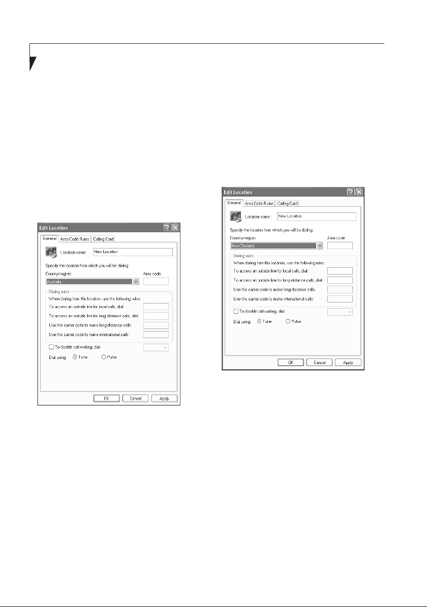
NOTE: Modem setting in Windows
XP
A. If you are located in Australia
1. Click Start select Control panel select
"Phone and Modem Options".
2. Double click New Location.
3. Choose "Australia" in Country/region pull
down menu bar.
4. Select Phone system as “Tone Dialing”.
5. Click OK and Apply.
B. If you are located in New Zealand
1. Click start select Control panel select
"Phone and Modem Options".
2. Double click New Location.
3. Choose "New Zealand" in Country/region
pull down menu bar.
4. Select Phone system as “Tone Dialing”.
5. Click OK and Apply.
NOTE:
The screens and illustrations shown in this
examples may slightly vary depending on the
operating environment that you have installed.
x
Page 11

Table of Contents
Table of Contents
NAMES OF THE PARTS AND
THEIR FUNCTIONS ...................... 1
Front features of the notebook .....................1
Left/Right features of the notebook ..............3
Top features of the notebook ........................ 6
Bottom features of the notebook ..................7
Rear features of the notebook...................... 8
OPERATING STATUS
INDICATOR LED ........................... 9
RUNNING THE NOTEBOOK
ON ITS BATTERY ......................... 11
Charging the battery .................................... 11
Running the notebook on its battery ............ 11
Checking the power level of the battery ....... 12
Low battery condition ................................... 13
USING FINGERPRINT
AUTHENTICATION ....................... 14
Characteristics of fingerprint
authentication ......................................... 14
Configuration of registration information ...... 15
Register log-in information on homepages .. 15
Log into homepages using fingerprint
authentication ......................................... 18
Change registration information ...................19
Save/Read registration information .............. 22
Setup window ............................................... 25
POWER SOURCES ........................... 28
Connecting the Power Adapters .................. 28
Power On ..................................................... 29
Power Off ..................................................... 29
CHANGING THE INTERNAL
BATTERY PACK ........................... 30
ADDING MEMORY ............................ 31
Where to install memory .............................. 31
Preparing necessary items .......................... 31
Installing memory module ............................ 31
Checking the memory capacity ....................34
TROUBLESHOOTING ....................... 35
Identifying the Problem ................................ 35
Specific Problems ........................................ 35
Troubleshooting Table .................................. 36
NOTE:
A copy of LifeBook User's Manual is located on
your Microsoft Windows Desktop and Software
Drivers CD. You can use this LifeBook User's
Manual to find out more information about the
functions and features of your notebook.
xi
Page 12
Getting to Know Your LifeBook
13
10 11 12
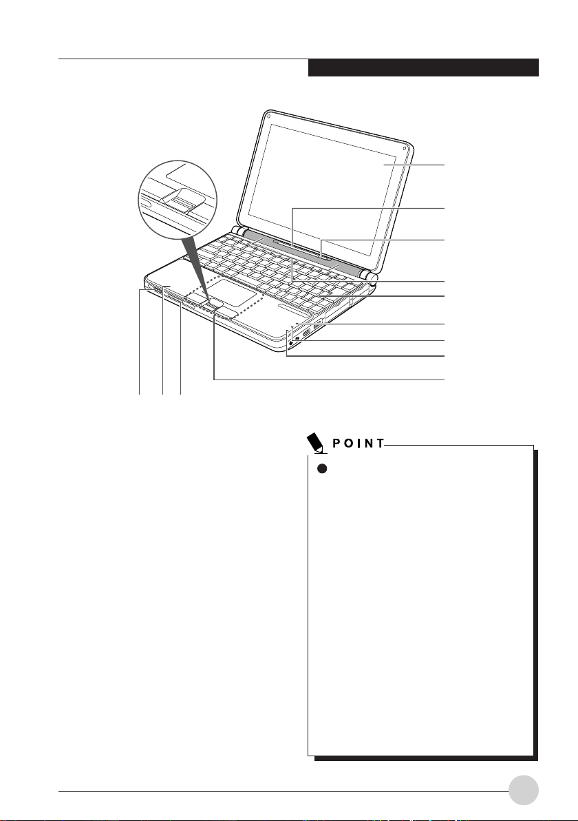
NAMES OF THE PARTS
AND THEIR FUNCTIONS
Front features of the
notebook
1. LCD Panel
The display screen of the notebook.
1
2
3
4
5
6
7
8
9
The phenomena described below are
characteristics of LCD panels and do not
indicate that LCD panels are defective.
The characteristics of LCD panels
• The TFT color LCD of your notebook,
composes of more than 2,350,000
picture elements (number of dots
when the screen resolution is set to
1024 by 768 pixels) or more than
2,940,000 picture elements (number
of dots when the screen resolution
is set to 1280 by 768 pixels), It is
manufactured using advanced
technologies. For technical reasons,
the LCD panel may have pixels that
do not light up or pixels that always
turn on. These do not indicate a
defective LCD.
• LCD panels may display slight
varying colors and uneven density as
environmental temperature changes.
1
Page 13
2. Status Indicator LED
This indicator displays symbols that
correspond to specific components on your
notebook.
3. Sus/Res Button
Power on or off the notebook. It also allows
you to put the notebook in standby mode
without turning off the power to the notebook.
Use this button to resume from standby
mode.
4. Speaker
The speaker produces stereo sound.
Be careful not to exert excessive
pressure on the speaker grille. Failure
to do so may damage it.
10. Wireless Switch
The switch allows you to turn on and off the
Wireless LAN communications.
Slide the switch to the right to turn it on, or
slide the switch to the left to turn it off.
Remember to off this switch where the use
of electronic devices is restricted, for
example, in hospitals and on airplanes.
Turn off this switch if you intend to carry your
notebook around. If you set your notebook
in standby mode with this switch on, the
notebook may resume operation
unexpectedly when it is carried around. This
may damage the hard disk.
11. Internal Microphone
It allows you to record the sounds and voices
in monaural.
12. SD Card/Memory Stick Slot
It allows you to insert an optional SD Card
or Memory Stick card and use it as a storage
device.
5. Keyboard
A 82-key keyboard with dedicated Windows
keys.
6. Numeric Lock Indicator
The Numeric Lock indicator states that the
internal keyboard is set in ten-key numeric
keypad mode.
7. Caps Lock Indicator
The Caps Lock indicator shows that your
keyboard is set to type in all capital letters.
8. Scroll Indicator
The Scroll Lock indicator states that Scroll
Lock is active.
9. Flat Point
It allows you to control the mouse pointer.
2
13. Fingerprint Authentication Sensor/Scroll
Button*
The Fingerprint authentication provides a
reliable, quick, and user-friendly alternative
to password which requires the user to recall
and enter cumbersome and often numerous
code combinations.
* Scroll Button
For model without Fingerprint Authentication
Sensor, this button used to scroll up and
down through a document in the window.
Some applications may not allow you to
scroll up and down through a document,
using the scroll button.
Page 14
Getting to Know Your LifeBook
1 2 3 4
5 6 7
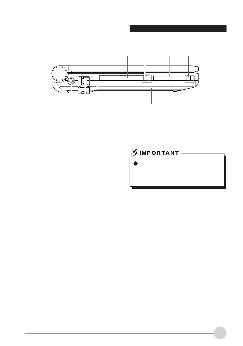
Left/Right features of the
notebook
Left Panel
1. PC Card Slot
It allows you to insert an optional PC card.
2. PC Card Eject Button
Press this button to eject a PC card.
3. CF Card Slot
It allows you to insert an optional Compact
Flash (CF) card and use it as a storage
device.
4. CF Card Eject Button
Press this button to eject the CF card.
5. DC-IN Jack
Plug in the supplied AC adapter into this port
to power your notebook and charge the
battery.
Before plugging a peripheral device into
a port on the notebook, orientate the
plug or connector of the cable correctly
and push it straight into the port.
6. Modem Port
It allows you to connect your notebook
internal modem to a phone line socket using
a supplied RJ-11 cable.
3
Page 15
7. Modular Bay
Your notebook comes with an internal Combo
Drive (DVD-ROM and CD-RW) or a DVD
SuperMulti (DVD-ROM, DVD ± RW, DVDRAM , CD-RW and CD-ROM) drive installed
in this modular bay. You can replace the
Combo Drive with an optional Weigth Saver
or optional second bay battery.
If this LifeBook come with an optical
drive that can read DVD titles, then this
drive is pre-set at factory to read DVD
title with region codes for specific Asia
Pacific markets (e.g. code 3 for Asian,
code 4 for Australia, code 6 for China).
The first time you play a DVD title with a
region code different from that of the
DVD optical drive - the region code set
at factory, you will be prompted to
change the region code of the DVD
optical drive. The region code of a DVD
optical drive can be changed up to 4
times, after which it will be locked so that
the DVD optical drive can only play DVD
titles of the final region code set.”
Do not leave your notebook with this bay
vacant. This may cause unexpected
system failure.
4
Page 16

5 6 7
Getting to Know Your LifeBook
1 2 3 4
Right Panel
1. LAN Port
It allows you to connect your notebook to a
LAN (local area network), using an optional
LAN cable.
2. IEEE 1394 (DV) Port
It allows you to connect a peripheral device
such as digital video camera (DVC) using a
DV cable.
3. Video Output (S-Video) Terminal
You can use a S-Video cable to connect the
notebook to a S-Video port on a TV.
4. External Monitor Port
The external monitor port allows you to
connect an external display monitor.
5. Headphone Jack/Optical Digital Audio
Output Terminal
• Headphone jack
It allows you to connect commercially
available headphones with a Ø3.5 mini
plug. This jack is not compatible with
certain types of connectors. Please
consult a salesperson on the specification
of the headphone before purchasing it.
• Optical digital audio output terminal
It allows you to connect the notebook to
an audio unit using a fiber-optic cable e.g.
an MD recorder with an optical digital
input terminal.
6. Microphone Jack
It allows you to connect a commercially
available monaural microphone with a Ø3.5
mini plug.
This jack does not support certain types of
microphones e.g. dynamic microphone.
Please consult a salesperson on the
microphone specification before purchasing
it.
7. USB Port
It allows you to connect an optional peripheral
device compliant with USB standard, such
as a USB floppy disk drive or USB printer.
5
Page 17
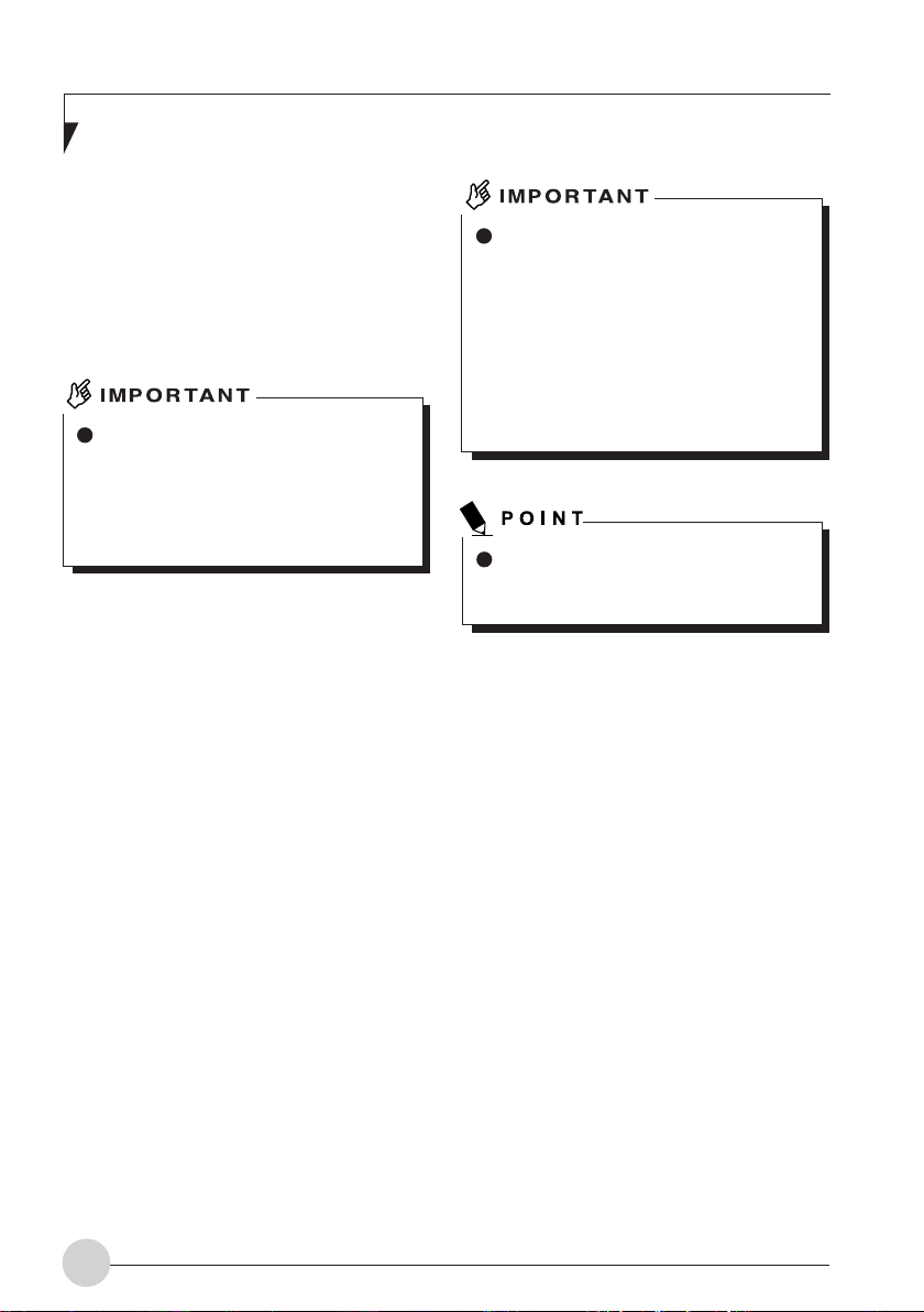
Top features of the notebook
1. Built-In Wireless LAN
The location of the dual Wireless LAN
antenna.
NOTE:
This is only applicable for notebooks with
Wireless LAN antenna.
1
6
Page 18
Getting to Know Your LifeBook
1
2
3
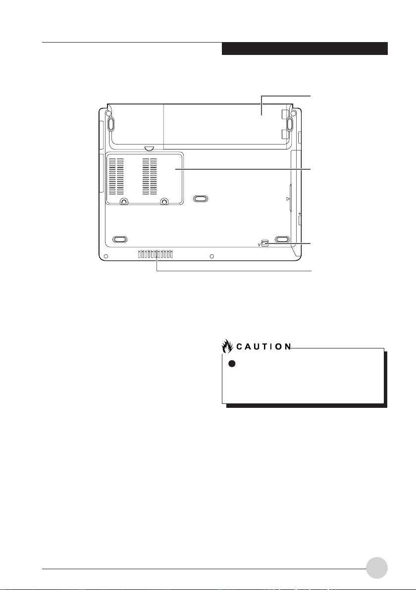
4
Bottom features of the
notebook
1. Internal Battery Pack
The internal battery pack is installed here.
2. Expansion RAM Module Slot
The location of the expansion memory slot.
3. Mobile Multi-Purpose Bay
Your notebook comes with an internal optical
disk drive, which may vary between
countries. Please check with your local
distributor for actual configuration. You may
change the installed optical disk drive with
other bay options. These are sold separately.
4. Air Inlet
This opening allows air to circulate inside the
notebook and cool it.
Be careful not to obstruct the air inlet.
Failure to do so prevent heat from being
dissipated from the notebook. This may
damage the notebook.
7
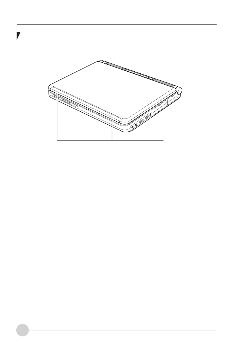
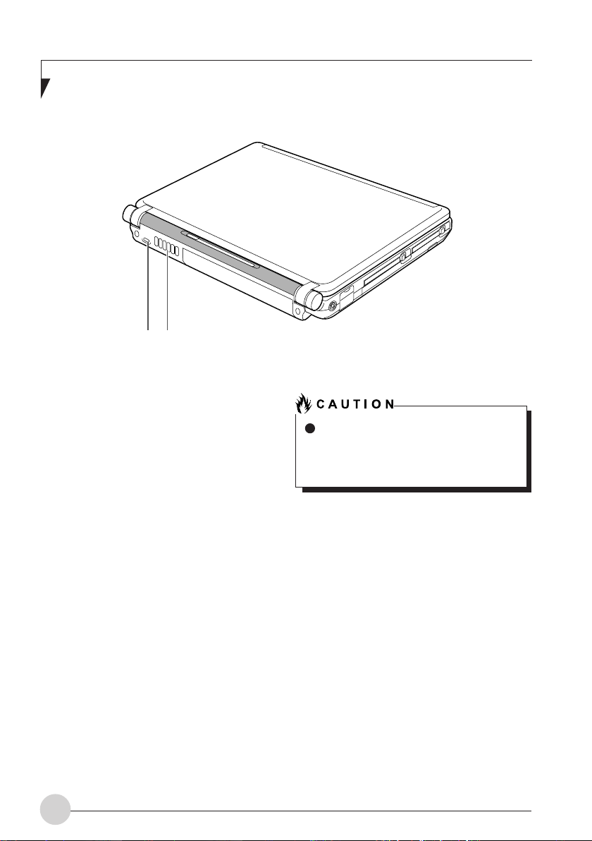
Page 19
1 2
Rear features of the
notebook
1. Anti-Theft Lock Slot
It allows you to attached a physical lock down
cable or device to prevent theft.
2. Air Outlet
Opening through which heat is forcibly
discharged from the notebook. When you
turn on the notebook, the cooling fan rotates
for a few seconds. When the temperature in
the notebook rises high, the cooling fan
automatically starts to rotate to discharge
heat from the notebook.
Do not obstruct the air outlet.
Doing so prevents heat from being
discharged from the notebook and could
result in damage to your notebook.
8
Page 20
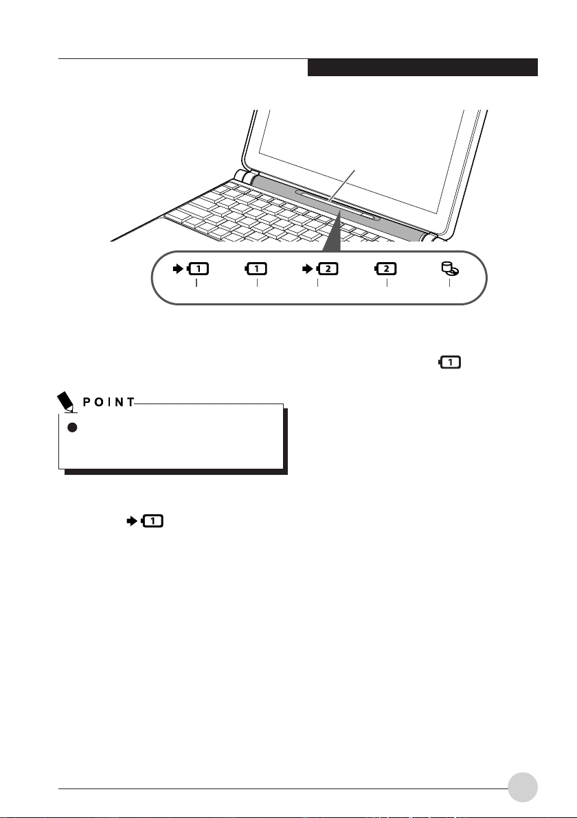
Getting to Know Your LifeBook
Status Display LED
1 2 3 4 5
OPERATING STATUS
INDICATOR LED
When the power is turned off, the status
display LEDs are all OFF except for
during battery charging.
1. Built-in Battery Pack Charging
Lamp ( )
This lamp indicates charging status of builtin battery when AC adaptor is connected to
PC.
• Green lamp is lit
Charging completed or not charging due
to no built-in battery pack installed.
• Orange lamp is lit
Charging
• Orange lamp flashes
Charging stopped (due to battery
temperature alarm, etc. [Note 1])
• OFF
No charging due to disconnected AC
adaptor.
2. Built-in Battery Pack Level
Indicator Lamp ( )
This lamp indicates remaining level of the
built-in battery pack.
• Green lamp is lit
Remaining battery level: 100% – 50%
[Note 2]
• Orange lamp is lit
Remaining battery level: 49 – 13% [Note
2]
• Red lamp is lit
Remaining battery level: 12% or below
[Note 2]
• Orange lamp flashes
Measuring remaining battery level (for 4
seconds after built-in battery pack is
installed)
• Red lamp flashes
Abnormal battery condition.
• OFF
Built-in battery pack disconnected.
9
Page 21
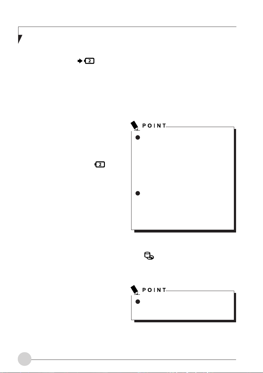
3. Extended Built-in Battery Unit
Charging Lamp ( )
This lamp indicates charging status of
extended built-in battery unit when AC
adaptor is connected to PC.
• Orange lamp is lit
Charging
• Orange lamp flashes
Charging stopped (due to battery
temperature alarm, etc. [Note 1])
• OFF
No charging due to disconnected AC
adaptor.
4. Extended Built-in Battery Unit
Level Indicator Lamp ( )
This lamp indicates remaining level of the
extended built-in battery unit.
• Green lamp is lit
Remaining battery level: 100% – 50%
[Note 2]
• Orange lamp is lit
Remaining battery level: 49 – 13% [Note
2]
• Red lamp is lit
Remaining battery level: 12% or below
[Note 2]
• Orange lamp flashes
Measuring remaining battery level (for 4
seconds after extended built-in battery
unit is installed).
• Red lamp flashes
Abnormal battery condition.
• OFF
Extended built-in battery unit
disconnected.
NOTE 1:
Battery temperature alarm is to stop
charging with battery protection function
when temperature of built-in battery pack
or extended built-in battery unit becomes
too high or too low due to battery heat or
cooling down of the battery.
NOTE 2:
Operational status or battery charging.
If built-in battery pack or extended builtin battery unit is installed when the
power is off, the battery level lamp
flashes in orange then indicates the
remaining battery level at the moment
for 5 seconds.
If AC adaptor is not connected or the
battery is fully charged, the lamp goes
off without indicating anything.
When in standby mode, the battery level
LED does not light up but flashes if AC
adaptor is not connected or the battery
is fully charged. Interval of the flash is
repetition of ON for 1 second and OFF
for 5 seconds.
5. Hard Disk/CD Access Lamp
( )
This lamp lights up when accessed to builtin hard disk or CD.
Data in the hard disk may be damaged
if the POWER button is operated while
the hard disk/CD access lamp is lit.
10
Page 22
Getting to Know Your LifeBook
RUNNING THE NOTEBOOK
ON ITS BATTERY
Charging the battery
1. Connect the AC adapter to your notebook.
2. The charging status indicator lights up.
It indicates whether the battery pack is being
charged.
3. When the charging status indicator turns
green, disconnect the AC adapter from
your notebook.
Charge the supplied battery pack before
using it for the first time after purchase
or if it is not recharged for more than
one month.
To fully charge the battery pack,
continue charging until the charging
status indicator turns green.
When the battery pack is 90% or more
charged, it cannot be recharged even
when the AC adapter is connected. The
battery pack can be recharged when its
power level (or remaining battery life) is
89% or less.
The chargeability of the battery pack
decreases when it is charged in a very
hot or cold place.
The battery temperature rises
immediately after the battery operation,
and the battery protection function may
operate, disabling the battery to be
charged. (If this happens, the charging
status indicator blinks orange.) When
the battery temperature comes down,
your notebook automatically restarts to
charge the battery pack.
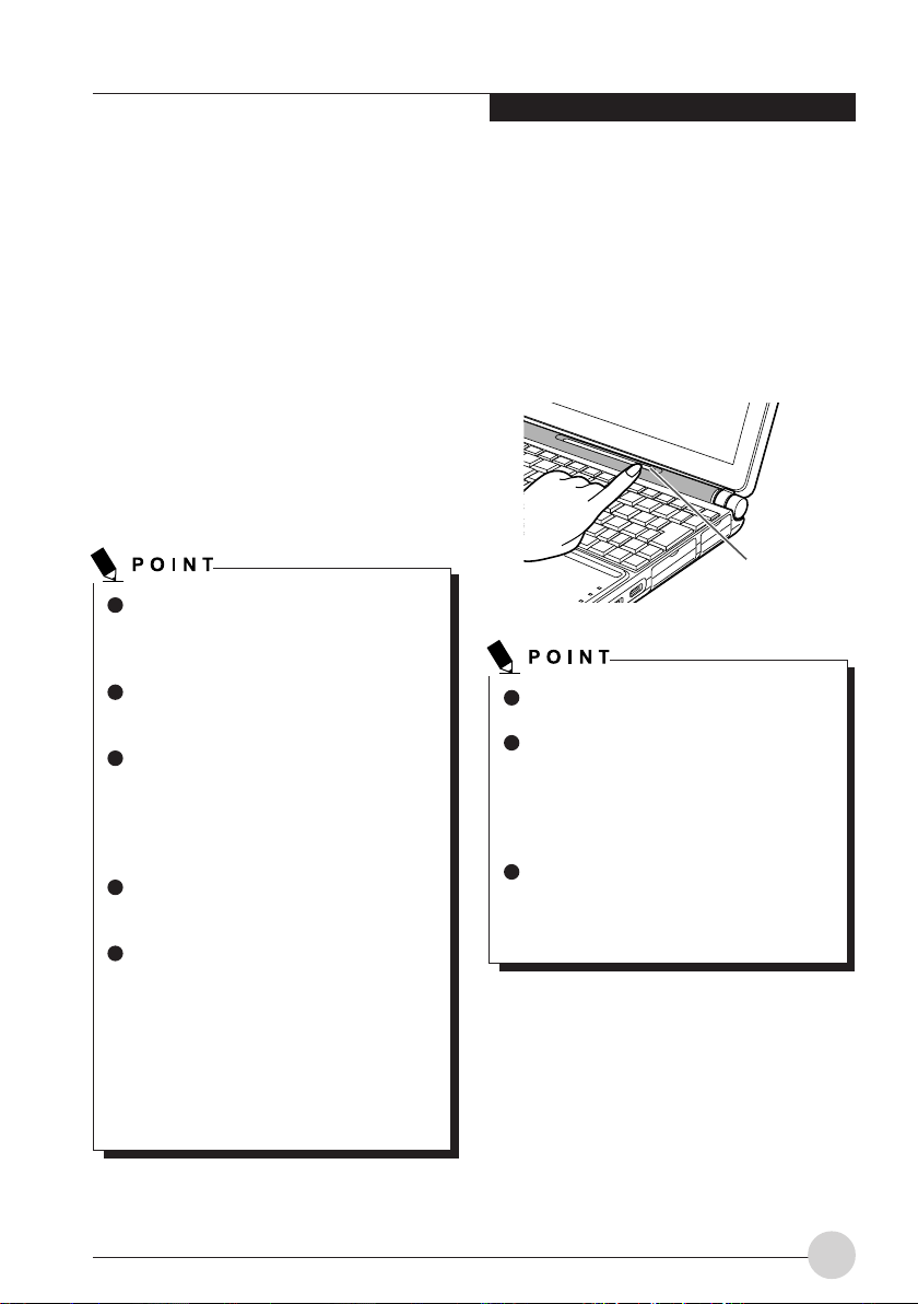
Running the notebook on its
battery
To run your notebook on its internal battery pack,
perform these steps.
1. Disconnect the AC adapter from your
notebook, and press the power button.
Power button
The operating time of the battery pack
shortens when it is used in a cold place.
The chargeability of the battery pack
decreases after it has been used over a
long period of time, and its operating
time shortens accordingly. If the battery
runs down quickly, replace it with a new
battery.
A rise in the battery temperature may
slow down your notebook. If this
happens, connect the AC adapter to
your notebook.
11
Page 23
Checking the power level of
the battery
Battery temperature alarm
(charging status indicator)
You can check the power level of the battery by
the battery power level show on the taskbar while
the power is on or the battery pack is being
charged.
For reasons of the characteristics of
lithium-ion batteries, the power level
indicator may not correctly indicate the
state of charge of the battery under
certain conditions (temperature
conditions, number of times the battery
has been discharged and recharged,
and so on).
When the battery pack is 90% or more
charged, it cannot be recharged even
when the AC adapter is connected. The
battery pack can be recharged when its
power level (or remaining battery life) is
89% or less.
If the battery pack becomes very hot or cold, the
charging status indicator will blink orange to tell
that the battery protection feature has been
activated and stopped charging the battery. When
the battery pack temperature returns to normal,
the charging status indicator stops blinking and
turns orange, and your notebook automatically
restarts to charge the battery pack.
Battery failure alarm (power level
indicator)
If the battery pack cannot be charged normally,
the power level indicator will blink red.
If the power level indicator blinks red,
turn off the notebook and remove and
reinstall the battery pack correctly. If the
power level indicator blinks red even
though the battery pack is installed
correctly, it is in a defective condition or
at the end of its useful life. Replace it
with a new one.
12
Page 24
Low battery condition
Getting to Know Your LifeBook
When the battery is discharged to a very low
level, the power level show on taskbar will give a
warning indicate low battery. If this happens,
connect the AC adapter to your notebook
immediately to recharge the battery.
The use of a low battery may result in
the loss of the data you are currently
creating or saving. Connect the AC
adapter to your notebook as soon as
possible. If no AC adapter is available,
immediately save the data you are
creating, exit all programs and turn off
your notebook.
Reading or writing data on the hard disk
requires a large amount of electric
power. Therefore, when the battery is
low, connect the AC adapter to your
notebook before reading or writing data
on the hard disk.
Leaving the battery low for a specific
period of time causes the notebook to
automatically go into standby mode.
When data is being read or written on
the hard disk, however, the notebook
does not go into standby mode until the
reading or writing of data is complete.
Your notebook is configured by default
to go into standby mode when the power
level reaches about 3%.
If you want to change this setting, follow
these steps: Open the “Power Options
Properties” dialog box, click the “Alarms”
tab, and then click the check box for
“Low battery alarm when power level
reaches” in the “Low battery alarm”
section ( changes to ).
If you change this setting, power supply
to your notebook will be cut off when
the battery goes dead. As a result, data
being saved or created might become
lost or your notebook might malfunction.
13
Page 25

USING FINGERPRINT
AUTHENTICATION
With fingerprint authentication, you can omit
entering a user name and a password by just
sliding your finger onto the fingerprint sensor at
the time of logging in homepages or logging on
Windows. This chapter describes how to use
fingerprint authentication.
NOTE:
This is only applicable for LifeBook with
Fingerprint Sensor.
To use fingerprint authentication, the user’s
fingerprints must be registered.
Characteristics of fingerprint
authentication
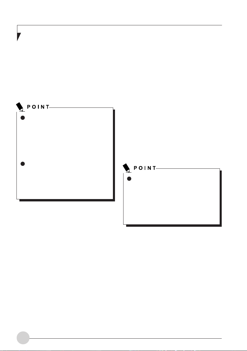
Fingerprint authentication can be
used in the following case.
• Logging on to Windows
When the user account of Windows is
password-protected, only persons who know
that password can log on to Windows using
that account. However, you have to enter the
password each time when you log on to
Windows.
With use of fingerprint authentication, you
can log on to Windows by only authenticating
fingerprints that have previously been
registered, thus omitting entering a
password.
• Recovery from the power-saving status
If the computer is password-protected for the
recovery from power-saving status, you have
to enter a password each time when your
computer is recovered from the power-saving
status.
With use of fingerprint authentication, you
can recover from the power-saving status by
authenticating fingerprints that have
previously been registered, thus omitting
entering a password.
You can log on
to Windows or
recover from the
power-saving
status by
authenticating
the fingerprints
It is unnecessary to input
a password.
• Canceling password-protected screen
saver
You can lock your computer if the screen
saver is password-protected. However, you
have to cancel this lock when canceling the
screen saver.
With use of fingerprint authentication, just
authenticating fingerprints that have
previously been registered enables this lock
to be canceled, thus omitting entering a
password.
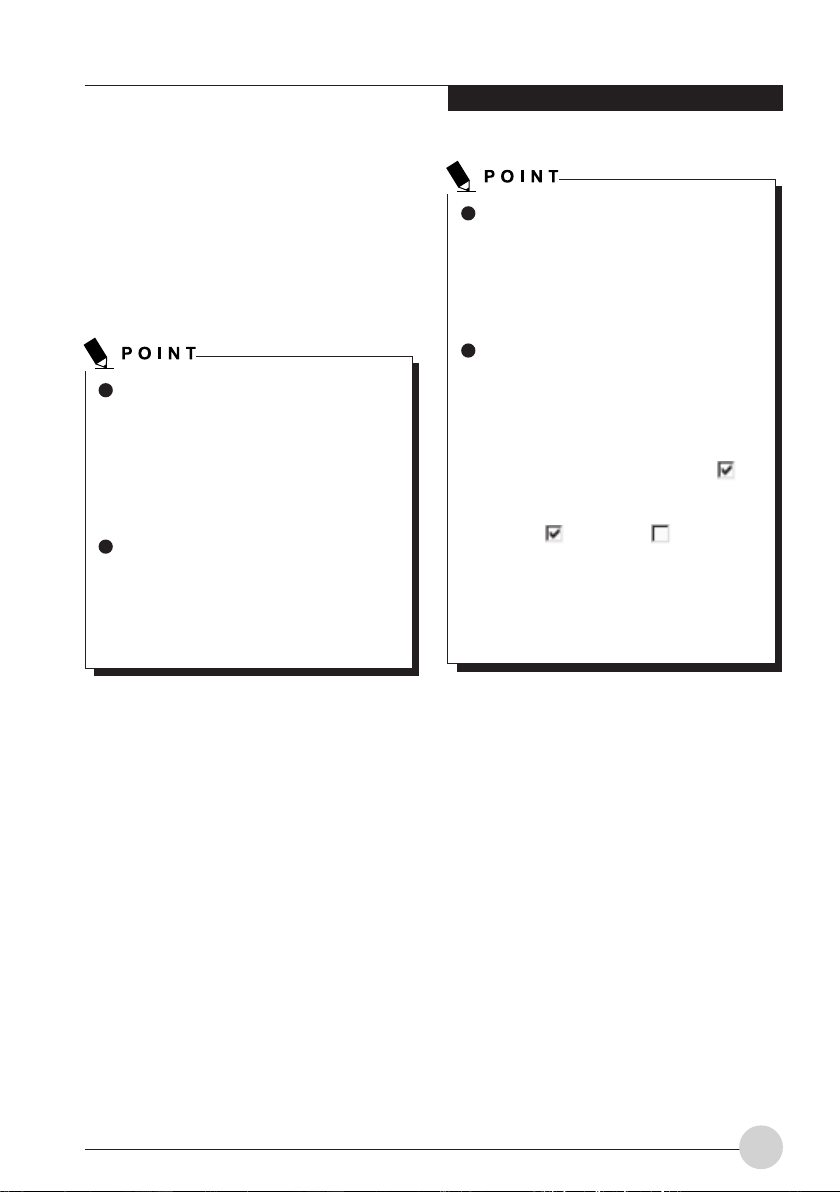
• Logging into the homepage that requires
an ID (user name) and a password
To log into the homepage of which security
is set up, you may have to enter log-in
information such as an ID (user name) and
a password.
With fingerprint authentication, you can log
into these homepages by just authenticating
fingerprints if log-in information is previously
memorized for specific homepages.
Status for entering log-in information differs
depending on homepages; direct entering
log-in information into homepages, and
indication of screens specific to entering. In
either case, log-in using fingerprint
authentication can be performed.
that have been
registered.
14
Page 26
Using Fingerprint Authentication
Configuration of registration
information
Registration information is set up in the following
configuration.
To use fingerprint authentication, it is necessary
to register the user’s fingerprint.
Registration information on
fingerprint authentication (User
name and password are just an
example.)
• User name
This is the user’s name for which a fingerprint
has been registered. It is necessary to give
the same name as used for logging on to
Windows.
• Domain
The full name of the computer is displayed.
• Fingerprint
Fingerprints are registered.
• Password
The user’s password for a user whose
fingerprint has been registered. It is
necessary to use the same password to be
used in logging on to Windows.
Register log-in information
on homepages
To log into homepages of which security is set
up, you may have to enter log-in information such
as an ID (user name) and a password.
With fingerprint authentication, you can log in
these homepages by only sliding your finger onto
the fingerprint sensor if log-in information is
previously memorized for specific homepages.
Register log-in information according to the
following procedure.
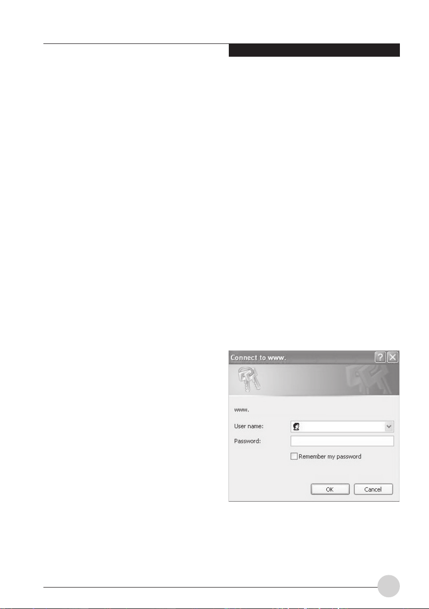
Register log-in information on
homepages
1. Display a homepage you want log-in
informating to be registered.
2. Enter log-in information.
• When directly registering log-in information
to homepage.
Do not press the “Sign-in” button, etc.
• Log-in information on homepages
Register an ID (user name) and a password
beforehand, so that homepages that require
entering an ID (user name) and a password
can be viewed just by authenticating
fingerprints.
15
Page 27
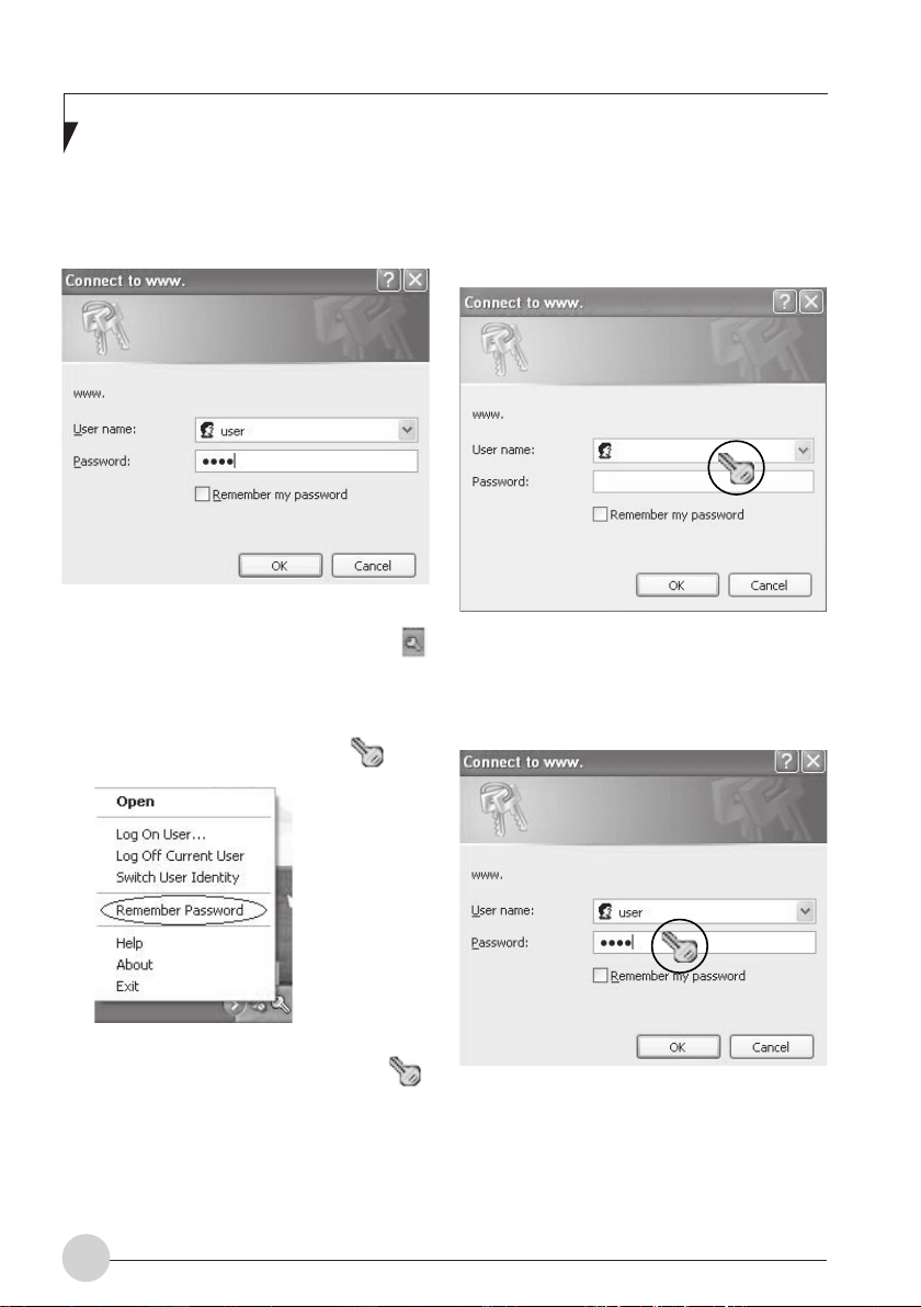
• When a screen specific for entering log-in
information is indicated.
Do not press the “OK” button.
• When directly registering log-in information
to homepage.
Click the area where a user name and a
password are entered.
3. Right-click on the OmniPass icon
from the notification area in the right
corner of the screen, and click on
“Memorize password.”
The mouse pointer changes into .
4. With the mouse pointer changed to ,
click on the area of log-in information
entered in Step 2.
The “OmniPass-Remenber Password”
window will appear.
16
• When a screen specific for entering log-in
information is indicated.
Click on the input screen.
Page 28
Using Fingerprint Authentication
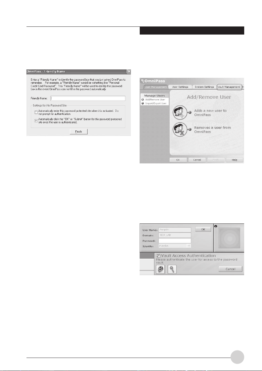
5. Enter the name of log-in information from
the “OmniPass-Friendly Name.
6. Click on “Finish.”
Registration of log-in information is completed.
The homepage that has been set here can be
logged in by just authenticating the registered
fingerprints without entering a user name and a
password.
Managing log-in information on
homepages
Information to be logged in homepages with
fingerprint authentication can be managed from
the following screen.
2. Click on “Vault management.”
The “Vault access authentication” window
appears.
3. Slide any finger of which fingerprints have
been registered onto the fingerprint
sensor.
When authentication of fingerprints is
successful, the “ID management” window will
appear.
1. Click on “Start,” “All programs,” “Softex”
and “OmniPass control center” in this
order.
The “OmniPass control center” window will
appear.
17
Page 29
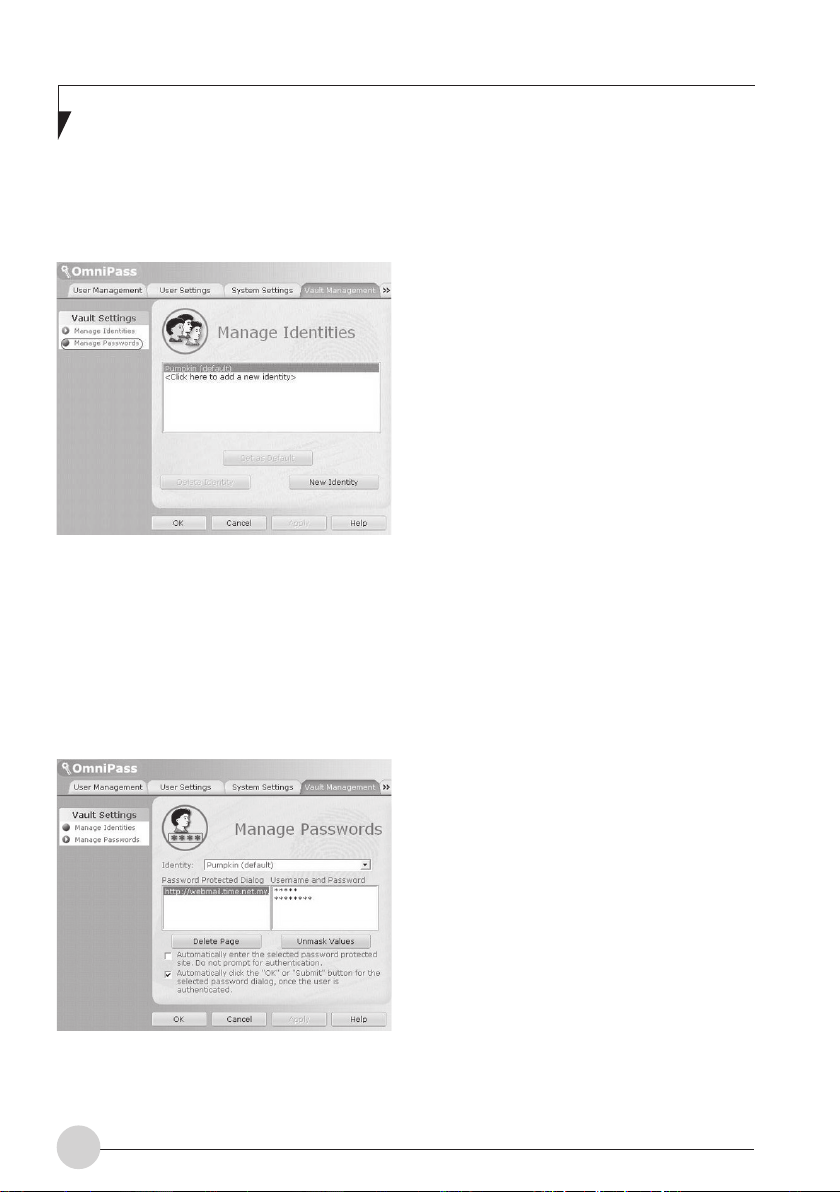
4. Select the user name, and click on
“Manage Passwords.”
The “Password management” window will
appear.
5. Log-in information is displayed on the
“Dialog protected by password.”
To change log-in information, it is necessary
to reregister log-in information. Select the login information name you desire to change,
and click on “Delete page.” Then, after log-in
information has been deleted, reregister the
log-in information to be registered.
Log into homepages using
fingerprint authentication
With fingerprint authentication, just by sliding your
finger onto the fingerprint sensor, you can log
into the homepage where security is set.
Register log-in information on
homepages
1. Display a homepage which log-in
information such as an ID (user name) and
a password are registered.
The “Access authentication” window will
appear.
2. Slide any finger of which fingerprint has
been registered onto the fingerprint
sensor.
When the authentication of fingerprints is
succeeded, log-in to a homepage will be
automatically performed.
18
Page 30
Using Fingerprint Authentication
Change registration
information
This chapter describes how to change the
information registered for using fingerprint
authentication.
After the registration of fingerprint
authentication has been completed, do
not change the user name that is
required for logging on to Windows and
the user name that has been set to the
registration information of fingerprint
authentication.
• Registration information
Registration information includes a user
name, a password, a fingerprint, and log-in
information on homepages. When
registration information is updated, delete all
of registration information such as a user
name and a password before reregistering
it.
However, when adding new fingerprints or
adding/deleting log-in information for
homepages, it is unnecessary to delete the
registered information on fingerprint
authentication.
• Fingerprint
The number of fingerprints to be registered
can be added. To delete the fingerprints
already registered, it is necessary to delete
all of registration information on fingerprint
authentication before reregistering it.
• Log-in information for homepages
When log-in information for homepages is
changed, before reregistering, it is necessary
to delete the log-in information that has been
registered. In this case, it is unnecessary to
delete registration information on fingerprint
authentication.
Deletes registration information
on fingerprint authentication
1. Click on “Start,” “All programs,” “Softex”
and “OmniPass control center” in this
order.
The “OmniPass control center” window will
appear.
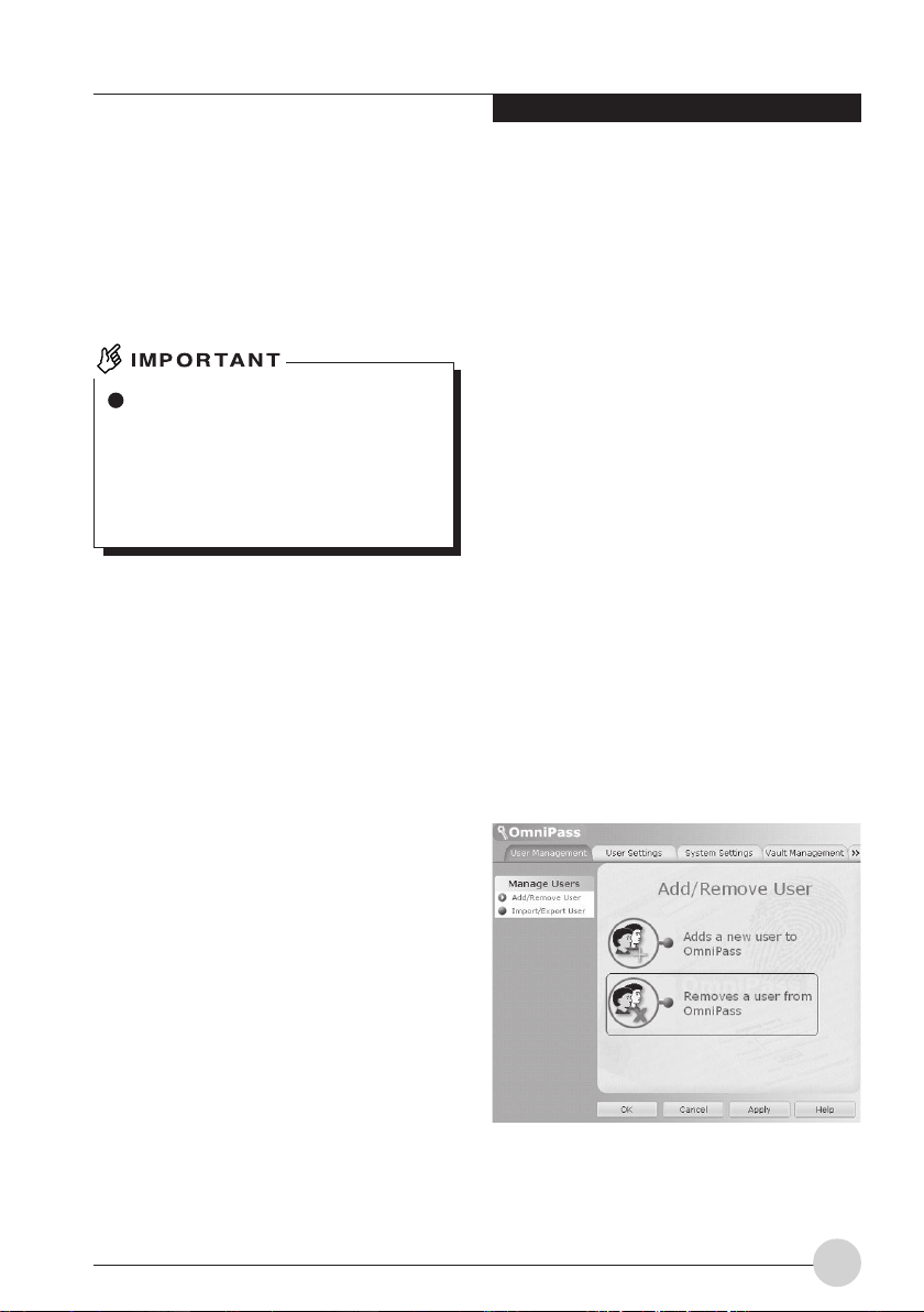
2. Click on “Remove users from OmniPass.”
The “Log-in user authentication” window will
appear.
• User name
Do not change a user name.
• Password
When a password for logging on to Windows
has been changed, it is necessary that the
password that has been set for registration
information for fingerprint authentication must
be changed to the password same as for
Windows after the change. When the
password that has been set for the
registration information on fingerprint
authentication is changed, delete all of
registration information on fingerprint
authentication before reregistering it.
19
Page 31

3. Slide any finger which fingerprint has
been registered onto the fingerprint
sensor.
When authentication of fingerprints is
succeeded, the “User delete confirmation”
window will appear.
4. Click on “OK.”
The message “A user has normally been
deleted” will be displayed.
Registration information on fingerprint
authentication has been deleted.
Adding registration information
to fingerprint authentication
1. Click on “Add new users to OmniPass.”
The “Confirmation of user name and
password” window will appear.
When “OmniPass control center” is not
displayed, click on the “Start” button -> “All
Programs” -> “Softex” -> “OmniPass control
center” in this order.
2. Enter the same password for logging on
to Windows and click on “Next.”
The “Select finger” window will appear. Do
not change a user name and domain.
20
Page 32

Using Fingerprint Authentication
3. Select a finger which fingerprint is
registered, and click on “Next.”
The “Fingerprint verification” window will
appear.
4 Slide a finger onto the fingerprint sensor
to confirm that a fingerprint has been
lifted. When “Fingerprint confirmation” is
completed, click on “OK.”
Perform “fingerprint verification” three times.
After three times of “fingerprint verification”
have been "successfull", slide your finger
again onto the fingerprint sensor for
“Fingerprint confirmation.”
5. When the message “Recommend to
register another finger” is displayed, click
on “Yes.”
The “Select finger” window will appear.
6. Perform Steps 3 to 5 again, and register
the fingerprint of another finger.
When the “Setting up audio and task bar”
window appears, proceed to Step 7.
7. Click on “OK” from the “Setting up audio
and task bar” window.
The “OmniPass user account has been
created” window appears.
8. Click on “Finish.”
9. When the message “Do you log on for a
new user” is displayed, click on “Yes.”
The “OmniPass control center” window
appears again.
10. Click on “OK.”
The “OmniPass control center” window will
be closed.
Re-registration of fingerprint authentication has
been completed.
21
Page 33

Save/Read registration
information
Information such as user names and passwords,
fingerprints and log-in information for homepages
that have once been registered can be saved
altogether. It is recommended that registration
information be saved in case where registration
information is mistakenly deleted.
Save registration information.
1. Click on “Start,” “All programs,” “Softex”
and “OmniPass control center” in this
order.
The “OmniPass control center” window will
appear.
2. Click on “Import/export of users.”
The “Import/export of users” window will
appear.
3. Click on “Export of OmniPass user
profile.”
The “Authentication of user export” window
will appear.
4. Authenticate the fingerprint registered.
When authentication of fingerprints is
succeeded, “Save users that have been
exported by providing a name” window will
appear.
22
Page 34

Using Fingerprint Authentication
5. Enter the name of the registration
information to save, and click on “Save.”
The message “User export has been
completed.” will be displayed.
Save in the “My document” folder as an
example. Any names can be used for the
registration information to be saved.
6. Click on “OK” from the message “User
export is completed.”
User’s export is completed, and registration
information is saved.
1. Click on “Start,” “All programs,” “Softex”
and “OmniPass control center” in this
order.
The “OmniPass control center” window will
appear.
2. Click on “Import/export of users.”
The “Import/export of users” window will
appear.
3. Click on “Import new users into
OmniPass.”
The “Open files to import users” window will
appear
Read registration information.
When no users are registered for
fingerprint authentication, the
“OmniPass registration wizard” window
may appear when starting the computer.
When importing registration information,
click on “Cancel.”
23
Page 35

4. Select the registration information that
has been saved and click on “Open.”
The “OmniPass import user” window will
appear.
How to confirm domain
“Domain” for setting the registration
information for fingerprint authentication
can be checked by the following
procedure.
1. Click on “Start.”
2. Right-click on “My Computer,” and
click on “Properties” in the menu
to be displayed.
The “System Properties” window will
appear.
3. Click on the “Computer Name”
tab.
5. Enter a user name, a domain, and a
password, then click on “Next.”
The message “User import of OmniPass has
been completed” will be displayed.
Enter the same user name and password to
be used in logging on to Windows.
4. A name that has been set to “Full
computer name” is “Domain.”
6. Click on “OK.”
7. Restart your computer.
Restarting the computer enables the
registration information that has been read
(imported) to be effective.
24
Page 36

Using Fingerprint Authentication
Setup window
Setting for fingerprint authentication can be
changed with “OmniPass control center.”
How to start “OmniPass control
center”
Start “OmniPass control center” in the following
procedure.
1. Click on “Start,” “All programs,” “Softex”
and “OmniPass control center” in this
order.
The “OmniPass control center” starts.
User Management
• Adding and deleting users
Users that use fingerprint authentication can
be added and deleted.
“Change registration information”
• User import/export
The user information that has already been
set can be saved (exported), or the user
information that is saved can be read
(imported).
“Save/Read registration information”
User settings
• Audio
Sound coming from the computer when
finger authentication is used is set.
• Display task bar hit
This setting is for messages to be displayed
in OmniPass icon in the notification area
in the bottom-right corner of your desktop
when Windows is logged on.
• Registration
In addition to the fingerprints that have
already been registered, new fingerprints can
be added and registered.
25
Page 37

System settings
• Starting option
Fingerprint authentication can be used for
logging on to Windows or you can terminate
its use.
• Password management
The user name and password for logging in
homepages by using fingerprint
authentication are managed. To change login information, delete log-in information once,
then reregister it.
Vault management
Manage information for logging into homepages.
When this setting screen is displayed, the
fingerprints that have already been registered are
to be authenticated.
“Register log-in information on homepages”
• ID management
A user ID (user name) to be logged in
homepages is managed.
26
Encrypt and Decrypt
It allows you to encrypt files and entire folders
with finger print sensor.
Page 38

Using Fingerprint Authentication
• File & Folder encryption
In order to encrypt a file or folder, click on
the folder or file to encrypt, right click on your
mouse button, choose “Omnipass Encrypt
File(s)”. Omnipass will then perform the
encryption on the file selected. To decrypt,
click on the file and right click on your mouse
button and choose “Omnipass Decrypt
File(s)”. Omnipass will decrypt your file for
viewing.
Please take note that certain files and folder
in Windows are not possible to encrypt.
Please refer to Omnipass help file in your
LifeBook for further information.
Version information
Version information on fingerprint authentication
utility is displayed.
Scrolling
The Fingerprint sensor now comes with a
scrolling function. Taking advantage of the
sensor’s technology, users will be able to scroll
up and down a document by swiping the finger
upwards to scroll up and swipe down to scroll
down.
27
Page 39

DC Output Cable
AC Cable
POWER SOURCES
DC Power Jack
AC Adapter
Connecting the Power
Adapter
The AC adapter provides power for operating
your notebook and charging the batteries.
Connecting the AC Adapter
1. Plug the DC output cable into the DC power
jack on your notebook.
2. Plug the AC adapter into an AC electrical
outlet.
28
The Lithium ion battery is not charged at the
point of purchase. Remember to connect the
AC adapter to your notebook to charge the
battery fully before you use it for the first time.
Page 40

Getting Started with your LifeBook
Notebook
Power On
Suspend/Resume/Power On Button
The Suspend/Resume/Power On button is used
to turn on your LifeBook notebook from its off
state. Once you have connected your AC adapter
or charged the internal Lithium ion Battery, you
can power on your notebook.
When you turn on your LifeBook be sure you
have a power source. This means that at
least one battery is installed and charged,
or that the AC adapter is connected and has
power.
Power button
Press the Suspend/Resume/Power On button.
When you have finished working on the
notebook, you can either leave it in Suspend
mode, or you can turn it off.
Do not carry your notebook around when it
is still power on. Do not subject your
notebook to shocks or vibrations. These may
damage your notebook.
When you Power On your LifeBook notebook, it
will perform a Power On Self Test (POST) to
check the internal parts and configuration. If an
error is found, your LifeBook notebook will emit
an audio warning and/or an error message will
be displayed.
After satisfactory completion of the Power On Self
Test (POST), your notebook will load the
operating system.
Power Off
Power/Suspend/Resume Button
Before turning off the power, check that the Hard
Drive, bay drive, PC Card and the Floppy Disk
Drive Access indicators are all Off. If you turn off
the power while the notebook is accessing the
disk or PC card, data may be lost. To shut down
the notebook with out error, use the Windows
shut down procedure.
Remember to close all files, exit all
applications, and shut down your operating
system prior to turning off the power using
the power switch. If documents are open
when you turn off the power, you will lose
data that have not been saved, and may
cause disk errors.
Remember to use the correct procedure to shut
down your notebook. The proper sequence is:
1. Click the start menu, and then click turn off
notebook button.
2. Click on the Turn Off button within the turn
off notebook dialog box.
3. The notebook automatically begins to shut
down.
29
Page 41

CHANGING THE
INTERNAL BATTERY
PACK
4. Install a new battery pack.
Align the stopper of the main unit of the
personal notebook with the slit of the internal
battery pack, and firmly insert the battery
pack so that the hook makes a sound.
Be sure to turn off your notebook before
changing the internal battery pack. Do
not touch any connectors on the
notebook or battery pack.
Otherwise, you might get an electric
shock or your notebook might break
down.
Changing the internal battery
pack
1. Turn off your notebook.
2. Close the LCD panel, and place the
notebook upside down.
Close the LCD panel carefully so as not
to give an impact to it. Failure to do so
could result in damage to the LCD panel.
3. Remove the internal battery pack while
pressing the hook in the arrow direction.
The internal battery pack is removed from
the connector.
Hook
After removing the internal battery pack,
take necessary measures to prevent it
from shorting, for example, sealing its
connector with an insulating tape. After
removing the internal battery pack, do
not mix it with other types of battery.
The internal battery pack (lithium-ion
battery) contains precious resources.
Therefore, you should dispose of the
disused battery pack as a recyclable
material if possible.
30
Hook
Hook
Page 42

User-Installable Features
ADDING MEMORY
Where to install memory
Your notebook has an expansion RAM module
slot (slot 2) to add in one additional memory
module.
The memory capacity of the notebook can be
increased to a maximum of 1 GB (512 MB x 2).
Preparing necessary items
• Philips screwdriver
Use a screwdriver of appropiate size to
remove the screws on the cover. Failure to
do so may damage the head of the screws.
Memory Module Configuration Table.
The table below shows combinations of
memory that can be installed on your
notebook.
The installation of any combination of memory
other than the combinations shown below can
impair the functioning of your notebook.
Total capacity Slot 1 Slot 2
256 MB 256 MB
384 MB 256 MB 128 MB
512 MB 256 MB 256 MB
768 MB 256 MB 512 MB
1 GB 512 MB 512 MB
Installing memory module
To install memory, perform these steps.
Before installing any memory module,
remember to power off the notebook
and disconnect the AC adapter from it.
Keep small objects, such as a cover,
caps and screws, out of the reach of
babies and children. These small
objects may suffocate a baby or child if
they are swallowed accidentally. Should
such an accident happen, consult a
doctor immediately.
Certain components around the
memory slots are very hot when the
notebook is powerd on for a long period
of time.
To avoid possible burns, do not install
or remove memory module immediately
after turning off the notebook but wait
for a while until its internal components
cool down.
To install or remove a memory module,
hold it by the edge and be careful not to
touch any component and IC.
Memory module is made of materials
sensitive to human body static charges.
Before handling a memory module,
always touch an appropiate metal object
to discharge static charges from your
body.
Please remember to turn off the
notebook before you begin to install or
remove a memory module. If the
notebook is placed in standby or
hibernate mode while the memory is
removed, data may be lost or corrupted.
This may also damage the memory
module.
31
Page 43

1. Turn off your notebook and disconnect
the AC adapter from it.
2. Close the LCD panel, and turn and place
your notebook upside down.
3. Remove the internal battery pack.
To avoid damage, do not to touch
internal components unnecessarily.
To avoid damage, be careful not to drop
any small object e.g. a screw into your
notebook.
4. Close the LCD panel, and turn and place
the notebook upside down.
6. Remove the memory.
If the claws on both sides, which are holding
the memory, are opened to the sides, the
memory can be lifted slightly diagonally
upward. Remove the memory from the slot
by pulling it diagonally upward.
Claw
(Slot 2)
5. Remove the screws (2 screws) to remove
the extended RAM module slot cover.
Open the extended RAM module slot cover
in the direction of the arrows to remove it.
Extended RAM module slot
cover
32
7. Attach the memory
Align the cutouts on the memory with lugs
on the connector, then insert the memory
from diagonally above and push it down until
click sound is heard.
Cutout on the
memory
• Cutouts on the memory and lugs on
the connector
Claw
Claw
Page 44

User-Installable Features
8. Attach the extended RAM module slot
cover.
Reattach the cover that was removed in the
Procedure 5 or 6.
Extended RAM module slot
cover
9. Attach the built-in battery pack.
Procedure 4 of “Replace the built-in battery
pack”.
Reattach the extended built-in battery
unit (accessory) if it was removed in the
Procedure 3.
33
Page 45

Checking the memory
capacity
If the memory is not installed correctly,
an error message “Expansion memory
error” may be displayed when you turn
on the notebook. If such a message
appears, turn off the notebook, remove
the memory and reinstall it.
1. Turn on the notebook.
2. Click the “Start” button and select
“Control Panel”.
The Control Panel window appears.
3. Click “Performance and Maintenance”,
and then “System”.
The “System Properties” dialog box appears.
4. Check if the circled numerical value in the
figure below has increased by the size of
memory you added.
Memory capacity
In this example, 256 MB of memory added
to a notebook.
* The system uses 8 MB of memory for internal
usage, so that a memory capacity smaller
than the actual installed memory capacity is
shown in this window.
5. Click “OK”.
The “Performance and Maintenance” window
appears again.
If the numerical value displayed does not
agree with the memory capacity of your
notebook, check if the memory is
installed correctly.
34
Page 46

Troubleshooting
TROUBLESHOOTING
Your Fujitsu LifeBook notebook is sturdy and
subject to few problems in the field. However, you
may encounter simple setup or operating
problems that you can solve on the spot or
problems with peripheral devices, that you can
solve by replacing the device. The information in
this section helps you isolate and resolve some
of these straightforward problems and identify
failures that require service.
Identifying the Problem
If you encounter a problem, go through the
following procedure before pursuing complex
troubleshooting:
1. Turn off your LifeBook notebook.
2. Make sure the AC adapter is plugged into
your notebook and to an active AC power
source.
3. Make sure that any card installed in the PC
Card slot is seated properly. You can also
remove the card from the slot, thus
eliminating it as a possible cause of failure.
4. Make sure that any devices connected to the
external connectors are plugged in properly.
You can also disconnect such devices, thus
eliminating them as possible causes of failure.
5. Turn on your notebook. Make sure it has been
off at least 10 seconds before you turn it back
on.
6. Go through the boot sequence.
7. If the problem has not been resolved, refer
to the Troubleshooting Table that follows for
more detailed troubleshooting information.
8. If you have tried the solutions suggested in
the Troubleshooting Table without success,
contact your support representative.
Before you place the call, you should have the
following information ready so that the customer
support representative can provide you with the
fastest possible solution:
• Product name
• Product configuration number
• Product serial number
• Purchase date
• Conditions under which the problem occurred
• Any error messages that have occurred
• Hardware configuration
• Type of device connected, if any
See the Configuration Label on the bottom of your
notebook for configuration and serial numbers.
Specific Problems
Using the Troubleshooting Table
When you have problems with your LifeBook
notebook, try to find the symptoms under the
Problem column of the troubleshooting table. You
will find a description of common causes for that
symptom under the column Possible Cause
Follow the instructions on the Possible Solution
column to resolve the problem. All possible
causes or solutions may not apply to your
notebook.
If you keep notes about what you have tried,
your support representative may be able to
help you more quickly by giving additional
suggestions over the phone.
35
Page 47

Troubleshooting Table
Problem Possible Cause Possible Solution
Audio Problem
There is no sound
coming from the
bulit-in speakers
The software volume
control is set too low.
Adjust the sound volume control settings in
your software, operating system and
applications.
Headphones are plugged
into your notebook.
BIOS audio settings are
incorrect.
Software driver is not
configured correctly.
The speakers have been
muted using the Volume
icon in the system tray.
Optical Drive Problems
LifeBook notebook
fails to recognize
DVD/CD-RW/ CDROM’s.
Protective sheet is still in
the optical drive tray.
DVD/CD-RW/CD-ROM is
not pushed down onto
raised center circle of the
drive.
Media tray is not latched
shut.
Incorrect DVD Player or
no DVD Player software is
installed.
Plugging in headphones disables the built-in
speakers, remove the headphones.
Set the BIOS setup utility to the default values
within the Multimedia Device Configuration
menu.
Refer to your application and operating system
documentation for help.
Click on the Volume icon in the tool tray on the
bottom right of the screen. (It looks like a
speaker.)
If the Mute box is checked, click on it to
uncheck it.
Remove the protective sheet and replace
DVD/CD-RW/CD-ROM in the tray.
Open media tray and re-install DVD/CD-RW/
CD-ROM properly.
Push on the front of the media tray until it
latches.
Install DVD Player software.
36
Wrong drive designator
was used for DVD/CDRW/CD-ROM in the
application.
Verify the drive designator used by the
application is the same as the one used by the
operating system.
When the operating system is booted from a
DVD/CD, drive designations are automatically
adjusted.
Page 48

Troubleshooting
Problem Possible Cause Possible Solution
Optical Drive Problems
LifeBook notebook
fails to recognize
DVD/CD-RW/ CDROM’s.
Windows DVD/CD-RW/
CD-ROM auto insertion
function is disabled.
Start the DVD/CD-RW/CD-ROM from the
desktop or application software or re-enable
the Windows DVD/CD-RW/CD-ROM auto
insertion function.
(continued)
The DVD/CD-RW/
CD-ROM Access
indicator on the
Status Indicator
Panel blinks at
regular intervals
when no DVD/CDRW/CD-ROM is in
the tray or the
optical drive is not
installed.
DVD/CD-RW/CD-ROM is
dirty or defective.
The Windows DVD/CDRW/CD-ROM auto
insertion function is active
and is checking to see if a
DVD/CD-RW/CD-ROM is
ready to run.
Wipe DVD/CD-RW/CD-ROM with a nonabrasive CD cleaning cloth and reinsert. It if
still will not work try another DVD/CD-RW/CDROM in the drive.
This is normal. However, you may disable this
feature.
37
Page 49

Problem Possible Cause Possible Solution
Hard Drive Problems
You cannot access
your hard drive.
Revise BIOS settings to set both Primary
Master and Primary Slave correctly.
The wrong drive
designator was used by
an application when a
bootable CD-ROM was
used to start the
notebook.
Security is set so your
operating system cannot
be started without a
password.
Keyboard or Mouse Problems
The built-in
keyboard does not
seem to work.
You have installed
an external
keyboard or
mouse, and it does
not seem to work.
You have
connected an
external keyboard
or a mouse and it
seems to be
locking up the
system.
The notebook has gone
into Suspend mode.
Your application has
locked out your keyboard.
Your external device is not
properly installed.
Your operating system
software is not set up with
the correct software driver
for that device.
Your operating system
software is not set up with
the correct software driver
for that device.
Your system has crashed.
Verify drive designator used by application is
in use by the operating system. When the
operating system is booted from a CD, drive
designations are automatically adjusted.
Verify your password and security settings.
Push the Power/Suspend/Resume button.
Try to use your integrated pointing device to
restart your system.
Re-install your device.
Check your device and operating system
documentation and activate the proper driver.
Check your device and operating system
documentation and activate the proper driver.
Try to restart your notebook.
38
Page 50

Troubleshooting
Problem Possible Cause Possible Solution
Memory Problems
Your Info menu of
the BIOS setup
utility does not
show the correct
amount of installed
memory.
Modem Problems
Your memory upgrade
module is not properly
installed.
You have a memory
failure.
Remove and re-install your memory upgrade
module.
Check for Power On Self Test (POST)
messages.
Messages about
modem operation.
Messages about modem
operation are generated
by whichever modem
application is in use.
See your application software documentation
for additional information.
39
Page 51

Problem Possible Cause Possible Solution
PC Card Problems
A card inserted in
the PC Card slot
does not work or is
locking up the
system.
The card is not properly
installed.
The card may have been
installed while an
application was running,
so your notebook is not
aware of its installation.
Remove and re-install the card.
Close the application and restart your
notebook.
Power Failures
You turn on your
LifeBook notebook
and nothing seems
to happen.
Your software may not
have the correct software
driver active.
You may have the wrong
I/O address selected for
the activated PC Card.
Your PC Card device and
another device are
assigned the same I/O
address.
The installed primary
battery is completely
discharged, there is no
optional second battery
installed or there is no
Power adapter (AC
adapter) installed.
The primary battery is
installed but is faulty.
The battery or batteries
are low.
See your software documentation and activate
the correct driver.
See your PC Card documentation to
determine the required I/O address. Change
the settings in the BIOS.
Check all I/O addresses located within the
BIOS setup utility and any other installed
hardware or software to make sure there are
no duplications.
Check the Status Indicator Panel to determine
the presence and condition of the batteries.
Install a charged battery or a power adapter.
Use the Status Indicator Panel to verify the
presence and condition of the batteries. If a
battery is indicating a short, remove that
battery and operate from another power
source or replace that battery.
Check the Status Indicator Panel to determine
the presence and condition of the batteries.
Use a power adapter to operate until a battery
is charged or install a charged battery.
40
The power adapter (AC
adapter) is not plugged
in properly.
Verify that your adapter is connected correctly.
Page 52

Troubleshooting
Problem Possible Cause Possible Solution
Power Failures
You turn on your
LifeBook notebook
and nothing seems
to happen.
(continued)
The power adapter (AC
adapter) has no power
from the AC outlet.
The power adapter (AC
adapter) is faulty.
Move the AC cord to a different outlet, check
for a line switch or tripped circuit breaker for
the AC outlet.
Try a different power adapter or install a
charged optional second battery.
Your LifeBook
notebook turns off
all by itself.
Your LifeBook
notebook will not
work on battery
alone.
The power management
parameters are set for
auto timeouts which are
too short for your
operating needs.
You are operating on
battery power only and
have ignored a low battery
alarm until the batteries
are all power drained
empty and your machine
has gone into Dead
Battery Suspend mode.
You have a battery failure.
Your power adapter has
failed or lost its power
source.
The installed batteries
are dead.
No battery is installed.
The batteries are
improperly installed.
Press any button on the keyboard, or move
the mouse to restore operation. If that fails,
push the Power/Suspend/Resume button.
Check your power management settings, or
close your applications and go to the Power
Options menu to adjust the timeout values to
better suit your needs.
Install a power adapter or a charged battery
and then push the Power/Suspend/Resume
button.
Verify the condition of the batteries using the
Status Indicator Panel, and replace or remove
battery that is shorted.
Make sure the adapter is plugged in and the
outlet has power.
Replace the battery with a charged one or
install a power adapter.
Install a charged battery.
Verify that the batteries are properly
connected by removing and re-installing them.
Your installed batteries
are faulty.
Verify the condition of the batteries using the
Status Indicator panel and replace or remove
batteries that are shorted.
41
Page 53

Problem Possible Cause Possible Solution
Power Failures
The batteries
seem to discharge
too quickly.
You are running an
application that uses a
great deal of power due to
frequent hard drive
access or DVD/CD-ROM
access, use of a modem
card or a LAN PC card.
Use both the primary battery and an optional
second battery and/or use a power adapter for
this application if possible.
The power savings
features may be disabled.
The brightness is turned
all the way up.
The batteries are very old.
The batteries have been
exposed to high
temperatures.
The batteries are too hot
or too cold.
Check the power management and/or setup
utility settings in the Power Options menu and
adjust according to your operating needs.
Turn down the brightness adjustment. The
higher the brightness the more power your
display uses.
Replace the batteries.
Replace the batteries.
Restore the notebook to normal operating
temperature. The Charging icon on the Status
Indicator Panel will flash when the battery is
outside its operating range.
42
Page 54

Troubleshooting
Problem Possible Cause Possible Solution
Shutdown and Startup Problems
The Power
Suspend/Resume
button does not
work.
The Power/Suspend/
Resume button is disabled
from the Advanced
submenu of the Power
Options menu.
Enable the button from the setup utility.
The system
powers up and
displays power-on
information, but
fails to load the
operating system.
An error message
is displayed on the
screen during the
boot sequence.
You did not hold the
button long enough to
activate this feature.
There may be a conflict
with the application
software.
The boot sequence
settings of the setup utility
are not compatible with
your configuration.
You have a secured
system requiring a
password to load your
operating system.
Internal hard drive was
not detected.
Power On Self Test
(POST) has detected a
problem.
Hold the button longer. This may require a few
seconds if your application is preventing the
CPU from checking for button pushes.
Close all applications and try the button again.
Set the operating source by pressing the
[ESC] key while the Fujitsu logo is displayed
on screen or use the [F2] key and enter the
setup utility and adjust the source settings
from the Boot menu.
Make sure you have the right password. Enter
the setup utility and verify the Security settings
and modify them as accordingly.
Use the BIOS setup utility or Primary Master
submenu, located within the Main menu, to try
to auto detect the internal hard drive.
See the Power On Self Test (POST) messages
to determine the meaning and severity of the
problem. Not all messages are errors; some
are simply status indicators.
43
Page 55

Problem Possible Cause Possible Solution
Shutdown and Startup Problems
Your notebook
appears to change
setup parameters
when you start it.
BIOS setup changes were
not saved when you made
them and exited the BIOS
setup utility.
Make sure you select Save Changes And Exit
when exiting the BIOS setup utility.
Your system
display will not turn
on when the
system is powered
on or when the
system has
resumed.
Video Problems
The built-in display
is blank when you
turn on your
LifeBook notebook.
The BIOS CMOS hold-up
battery has failed.
The system may be
password protected.
The notebook is set for an
external monitor only.
The angle and brightness
of the display are not
properly set at your
lighting conditions.
Contact your support representative for
repairs. This is not a user serviceable part. The
part has a normal life span of 3 to 5 years.
Check the status indicator panel to verify that
the Security icon is blinking. If it is blinking,
enter your password.
Pressing [F10] while holding down the [Fn] key
allows you to change your selection of where
to send your display video. Each time you
press the combination of keys you will step to
the next choice. The choices, in order, are:
built-in display only, external monitor only, both
built-in display and external monitor.
Move the display and the brightness control
until you have adequate visibility.
44
Page 56

Troubleshooting
Problem Possible Cause Possible Solution
Video Problems
The LifeBook
notebook turned
on with a series of
beeps and your
built-in display is
blank.
Power On Self Test
(POST) has detected a
failure which does not
allow the display to
operate.
Contact your support representative.
The display goes
blank by itself after
you have been
using it for a period
of time.
Your system
display won’t turn
on when the
system is turned
on or when the
system has
resumed.
The built-in display
does not close.
The built-in display
has bright or dark
spots.
The notebook has gone
into Video timeout,
Standby mode, Suspend
mode or Save-to-Disk
mode because you have
not used it for a period of
time.
The system may be
password protected.
A foreign object, such as a
paper clip, is stuck
between the display and
the keyboard.
If the spots are very tiny
and few in number, this is
normal for a large LED
display.
If the spots are numerous
or large enough to
interfere with your
operation needs.
Press any button on the keyboard, or move
the mouse to restore operation. If that fails,
push the Power/Suspend/Resume button.
Check your power management settings, or
close your applications and go to the Power
Savings menu of the setup utility to adjust the
timeout values to better suit your operation
needs.
Check the Status Indicator Panel to verify that
the Security icon is blinking. If it is blinking,
enter your password.
Remove all foreign objects from the keyboard.
This is normal; do nothing.
Display is faulty; contact your support
representative.
45
Page 57

Problem Possible Cause Possible Solution
Video Problems
The application
display uses only a
portion of your
screen and is
surrounded by a
dark frame.
You are running an
application that does not
support 800 x 600/1024 x
768 pixel resolution full
screen display
You can fill the full screen at lower resolution
by changing the display compensation setting
in the BIOS. (See the Video Features
submenu, located within the Advanced menu
of the BIOS.)
Enabled video compensation and press [Fn] +
[F5] to maximized the screen to full screen
display at lower resolution 800x600 pixels.
The display is dark
when on battery
power.
You have
connected an
external monitor
and it does not
display any
information.
You have
connected an
external monitor
and it does not
come on.
Miscellaneous Problems
An error message
is displayed on the
screen during the
operation of an
application.
The Power Management
utility is set to low
brightness to conserve
power.
Your BIOS setup is not set
to enable your external
monitor.
Your external monitor is
not properly installed.
Your operating system
software is not set up with
the correct software driver
for that device.
Your external monitor is
not compatible with your
LifeBook notebook.
Application software often
has its own set of error
message displays.
Press [Fn] + [F7] to increase brightness or
double-click on the battery gauge and adjust
Power Control under battery settings.
Try toggling the video destination by pressing
[Fn] and [F10] together, or check your BIOS
setup and enable your external monitor. (See
the Video Features submenu, located within
the Advanced Menu of the BIOS.)
Reinstall your device.
Check your device and operating system
documentation and activate the proper driver.
See your monitor documentation and the
External Monitor Support portions of the
Specifications section.
See your application manual and help displays
screens for more information. Not all
messages are error messages, some may
simply be status indicators.
46
Page 58

版權
版權
富士通有限公司會盡力保証本文檔內容的準確
性和完整性。但是﹐由於我們仍在不斷改進產
品的功能﹐因此不能確保本文檔沒有任何差
錯。對於文檔中錯誤﹑疏忽或以後的修改我們
不承擔任何責任
LifeBook 是富士通有限公司的商標
Microsoft﹑Windows﹑MS﹑MS-DOS 和 Windows NT
是 Microsoft Corporation 在美國和其它國家或地區
的註冊商標
Phoenix 是美國 Phoenix Technologies Corporation 的
註冊商標
版權所有© 1981-1999 Microsoft Corporation﹐保留
所有權利
版權所有© 1999 Phoenix Technologies, Ltd., 保留所
有權利
。
。
。
。
。
。
其它所有產品是其各自公司的商標或註冊商標
©版權所有 2004 Fujitsu Limited﹐ 保留所有權利
未經富士通有限公司事先書面同意﹐嚴禁拷貝﹑
複製或翻譯本出版物中的任何內容。未經富士通
有限公司書面同意﹐嚴禁以任何電子形式存儲或
傳輸本出版物中的任何內容
操作使用應符合以下兩項條件:
(1) 本設備不能造成有害干擾
(2) 本設備必須能承受接收到的干擾﹐包括會造
成意外操作的干擾
網站: www.pc-ap.fujitsu.com
。
。
。
。
。
根據 FCC 第 15 部分內容
本設備遵循 FCC 規則的第 15 部分
(1) 本設備不準造成有害的干擾
包括會造成意外操作的干擾
一致性聲明
設備操作必須符合下列兩項條件:
。
(2) 本設備必須接受任何接收到的干擾﹐
。
。
i
Page 59

重要安全說明
1. 請仔細閱讀這些說明﹐ 並保存起來以備以後
參考
。
2. 遵循本產品上標示的所有警告和指示
3. 清潔之前先從牆上插座上拔下本產品的電源
線。切勿使用液體或噴霧清潔劑。使用濕布
進行清潔
4. 不要在靠近水的地方使用本產品
5. 不要將本產品放在不穩定的車輛﹑支架或桌
子上。以免產品跌落﹐造成嚴重損壞
6. 機殼上﹑背部和底部的槽口用於通風目的
為確保本產品的可靠運行﹐不至於出現過熱
高溫﹐嚴禁堵塞和蓋住這些槽口。嚴禁將本
產品放在床﹑沙發﹑地毯或其它類似表面
上﹐從而造成這些槽口的堵塞。切勿將本產
品靠近散熱器或電熱器﹐或放在它們的上
面﹐也不要將本產品放在箱內﹐除非通風條
件良好
7. 只能按照標簽上註明的電源類型使用本產
品。如果您不確定可用的電源類型﹐請諮詢
經銷商或當地的電力公司
8. 本產品配備有一個符合本地標準的插頭。如
果您面對問題﹐請和電工聯繫檢查插座
。
。
。
。
。
。
。
。
9. 不要將任何物品壓在電源線上。本產品的電
源線不應位於人們經常出入的地方
10. 如果使用本產品需要延長電線﹐一定要確保
接入延長電線上設備的額定安培總數不超過
延長線的額定安培數。也要確保接入牆上插
座上所有產品的總額定值不會超過 15 安培
11. 嚴禁將任何物品通過機殼的槽口插入到本產
品﹐這樣可能會碰到高壓部件﹐造成火災或
電擊。切勿將任何液體洒到本產品上
12. 不要嘗試自行維修本產品﹐打開或卸下護蓋
可能會使您遭到電擊﹐或其它危險。請務必
請專業的維修人員進行維修
13. 如果出現以下情況﹐應從牆上插座拔下本產
品的電源線﹐請專業的維修人員進行維修:
a. 電源線或插頭損壞或磨損
b. 產品內濺入了液體
c. 產品遭到雨淋或進水
d. 正常操作情況下﹐產品運行不正常。只調整
操作說明中介紹過的那些控制﹐因為不正確
地調整其它控制可能會造成損壞﹐通常需要
合格的技術人員花費更大的精力維修產品
e. 產品跌落﹐或機殼損壞
f. 產品性能出現明顯變化﹐需要進行維修
。
。
。
。
。
。
。
。
。
。
ii
Page 60

14. 注意。更換電池時一定要確保電池裝入的極
性位置正確。更換的電池類型不正確或處理
不當﹐會有爆炸的危險。切勿對電池充電﹑
折解或投入火中。只應使用製造商建議的相
同或同類電池更換。並按照製造商的說明處
理用過的電池
15. 只使用專供本裝置使用的正確類型的電源線
組(附件箱中提供)。它應是可分開的類
型:UL 認証∕CSA 認証﹐BS1363﹑ASTA﹑
SS145 認証﹐額定 10A 250V 最小﹐VDE 認
証或等同。最大長度為 15 英尺(4.6 米)
。
。
iii
Page 61

UL 聲明
該裝置需要交流適配器才能使用。並且只能使用
獲得 UL 認證﹐額定輸出為 16VDC﹐3.75A 的 2 類
適配器。請參考以下示意圖以瞭解正確的交流適
配器輸出極性
。
+
注意
為降低火災危險﹐只應使用 #26 號 AWG
或更大的通信電話線
授權修理技術人員須知
注意
為防止火災的發生﹐只應使用相同類型
和額定值的保險絲進行更換
警告
如果鋰(CMOS)電池更換不當﹐會有
爆炸的危險。只應使用相同的或製造商
建議的同類電池進行更換。按照製造商
的說明處理用過的電池
。
。
。
正確處理電池
在聯邦﹑國家或地區法律中﹐將電池扔進垃圾箱
或垃圾桶的處理方法是非法的。請保護我們的環
境﹐並正確處理電池。關於回收或處理不想要的
電池﹐請與當地政府權力機關協商
。
iv
Page 62

版權
要求高安全性的應用
本產品系為一般應用領域設計﹑開發和製造﹐包
括但不限於一般辦公使用﹑個人使用﹑家庭使用
和普通行業使用﹐如果沒有極高的安全保障﹐則
本產品不適用於伴隨有嚴重風險或危險﹐可能會
直接導致死亡﹑人身傷害﹑嚴重物理損壞或其它
損失的應用(簡稱“要求高安全性的應用”)﹐
包括但不限於核設施中的核能反應核心控制﹑航
空自動導航﹑空中管制﹑大型運輸控制系統的運
行控制﹑用於生命維持系統的醫療儀器﹐以及武
器系統中的導彈發射控制。如果不能完全滿足
“要求高安全性的應用”要求﹐則嚴禁使用本產
品
。
數據存儲介質與客戶責任
對電腦(如硬碟)中所存儲數據唯一有效的保護
方法是購買者定期備份數據。富士通及其附屬機
構﹑供應商﹑服務提供商﹑零售商對於退回給富
士通或其服務提供商進行保修服務或做其它修理
的任何媒體上或產品任何部分上存儲或使用的所
有軟件程序﹑數據或其它信息﹐包括但不限於恢
復這些程序﹑數據或其它信息的費用﹐不承擔任
何責任。在退回給富士通或指定維護中心進行保
修服務或做其它修理時﹐對所有存儲媒體或產品
任何部分上存儲的所有軟件程序﹑數據或信息進
行備份是購買者的責任
。
v
Page 63

目錄
部件名稱及其功能 .............................. 1
計算機前面功能配置 ........................................... 1
計算機左面∕右面功能配置 .............................. 3
筆記本電腦的頂部特征 ...................................... 6
筆記本電腦的底部特征 ...................................... 7
筆記本電腦的背面 ............................................... 8
操作狀態指示燈 .................................. 9
靠電池運行電腦 .................................. 11
電池充電 ................................................................ 11
靠電池運行電腦 ................................................... 11
檢查電池的電量 ................................................... 12
電池電量不足狀態 ............................................... 13
使用指紋驗証...................................... 14
指紋驗証的特點 ................................................... 14
設置註冊信息 ....................................................... 15
在首頁上註冊登彔信息 ...................................... 15
使用指紋驗證登彔到首頁 .................................. 18
更改註冊信息 ....................................................... 19
儲存∕讀取註冊信息 ........................................... 22
設定視窗 ................................................................ 25
電源 .................................................... 28
連接電源適配器 ................................................... 28
開機 ........................................................................ 29
關機 ........................................................................ 29
更換內部電池組 .................................. 30
增加內存 ............................................. 31
何處安裝內存 ....................................................... 31
準備工作 ................................................................ 31
安裝內存模塊 ....................................................... 31
檢查內存容量 ....................................................... 34
疑難解答 ............................................. 35
識別問題 ................................................................ 35
具體問題 ................................................................ 35
疑難解答表 ............................................................ 36
註:
LifeBook 用戶說明書位于微軟 Windows 桌面和軟件
驅動程序光盤上。您可以使用此 LifeBook 用戶說明
書找到您的筆記本電腦的各種功能和特點的更詳細
信息
。
vi
Page 64

了解您的 Li f e Book
要點
10 11 12
部件名稱及其功能
計算機前面功能配置
1. LC D面板
筆記本的顯示屏幕
。
13
1
2
3
4
5
6
7
8
9
下述現象是 LCD 面板的特點﹐并不表示
LCD 有缺陷
關于 LCD 面板的特點
•
• 如果環境溫度有所變化﹐則 LCD 面
。
計算機的TFT彩色 LCD 由 2,350,000 多
個圖形元素(屏幕分辨率被設置為
1024 x 768 像素時的點數)或 2,940,000
多個圖形元素(屏幕分辨率被設置為
1280 x 768 像素時的點數)組成﹐采
用高科技制造。由于技朮原因﹐您的
LCD 面板可能有一些像素不亮或有些
像素一直亮﹐但這并不表示 LCD 面板
有故障
。
板將顯示輕微的色彩變化和不均勻的
密度
。
1
Page 65

2. 狀態指示 LED
要點
此指示顯示與筆記本特定部分相關的符號
3. 暫停∕恢復按鈕
用來打開和關閉計算機。此按鈕也可以讓您
在不關閉筆記本電源的情況下使機器進入待
機模式。從待機模式恢復也使用此按鈕
4. 揚聲器
揚聲器產生立體聲聲音
要點
請勿用力壓揚聲器的格柵以免造成損
壞
。
5. 鍵盤
有專用 Windows 鍵的 82 鍵鍵盤
6. 數字鎖定指示燈
數字鎖定指示燈表示內部鍵盤被設定在十鍵
數字小鍵盤模式
7. 大寫鎖定指示燈
大寫鎖定指示燈表示您的鍵盤被設定為輸入
所有大寫字母
8. Scrlk(滾動鎖定)指示燈
滾動鎖定指示燈表示滾動鎖定已經啟用
9. 滑動鼠標面板
用來操作鼠標指針
。
。
。
。
。
10. 無線開關
。
。
。
用來打開和關閉無線 LAN 通訊
將開關撥到右邊可以打開它﹐拔到左邊可以
關閉它
。
在限制使用電子設備的地方﹐如醫院和機
場﹐請關閉這個開關。在攜帶計算機時您也
應關閉這個無線開關
當計算機處于待機模式﹐可以隨時恢復操作
時﹐使這個開關保持在打開狀態可能會造成
攜帶過程中計算機意外恢復操作﹐并可能會
造成硬盤驅動器故障
11. 內置麥克風
能使您以單聲道錄製聲音和語音
12. SD 卡∕記憶棒插槽
用來插入可選的 SD 卡或記憶棒作為存儲設備
使用
。
13. 指紋驗證感應器∕滾動按鈕*
指紋驗證提供了一種可靠﹑快速﹑用戶界面
友好的用於代替密碼的方法﹐而這些密碼需
要用戶調用並輸入繁瑣且時常是大量的代碼
組合
。
* 滾動按鈕
用於不帶指紋驗證感應器的機型﹐此按鈕用
於窗口內文件的上下滾動
有些應用程序可能不允許您使用滾動按
鈕上下滾動文件
。
。
。
。
。
。
2
Page 66

1 2 3 4
5 6 7
了解您的 Li f e Book
計算機左面∕右面功能配置
左面板
1. PC 卡彈出按鈕
按這個按鈕可以彈出 PC 卡
2. PC 卡插槽
用來插入可選的 PC 卡
3. CF 卡插槽
可使您插入選購的 Compact Flash(CF)卡
以作為存儲設備使用
4. CF 卡彈出按鈕
按下這個按鈕可以彈出 CF 卡
。
。
。
。
5. 直流輸入插孔
在此端口插入隨機提供的交流適配器以對計
算機供電并給電池充電
重要
﹐
6. 調制解調器端口
可使您用隨機提供的 RJ11 電纜將筆記本的內
置調制解調器連接至電話線路插口
。
在將一個外設插接到計算機上的一個端
口時﹐先確定插頭插入的方向正確﹐然
后再徑直插入到端口
。
。
3
Page 67

7. 模塊插槽
要點
重要
這款計算機的模塊插槽中裝有內置 Combo 驅
動器(DVD-ROM 和 CD-RW)或 DVD
SuperMulti(DVD-ROM﹐DVD±RW﹐DVDRAM﹐CD-RW 和 CD-ROM)。您可以將這個
Combo 驅動器換成空盒(Weight Saver)或第
二個插槽電池
重要
如果此 LifeBook 配有能讀取 DVD 標題的
光驅﹐則此光驅的出廠預設為讀取帶有
為亞太市場指定的地區代碼的 DVD 標題
(例如﹐亞洲代碼為 3﹐澳大利亞代碼為
4﹐中國代碼為 6)
。
。
當首次播放帶有地區代碼的 DVD 標題
時﹐而此代碼與 DVD 出廠設定地區代碼
不同﹐則將會提醒您更改 DVD 光驅的地
區代碼。 DVD 光驅的地區代碼最多可更
改 4 次﹐此後 DVD 光驅將被鎖定﹐因此
只能播放最後設定的地區代碼的 DVD 標
題
。
請不要在多用槽空置的情況下使用計算
機。這樣可能會造成計算機故障
。
4
Page 68

5 6 7
了解您的 Li f e Book
1 2 3 4
右面板
1. LAN 端口
可使您用選購的 LAN 電纜將筆記本連接至
LAN(本地局域網絡)
2. IEEE 1394(DV)端口
用來通過 DV 電纜將外設﹐如數碼攝像機
(DVC)連接到計算機
3. 視頻輸出(S-Video)端子
使用 S-Video 電纜適配器將筆記本連接到電視
上的 S-Video 端口中
S-Video 電纜適配器單獨出售
4. 外接顯示器端口
外接顯示器端口用于連接外部顯示器
5. 耳機插孔∕光學數字音頻輸出端子
• 耳機插孔
用來連接可以從市場上買到的 3.5mm 迷你
型插頭耳機。這種插孔與有些類型的電纜
接口不兼容﹐因此在購買耳機之前應咨詢
銷售人員
。
。
。
。
。
• 光學數字音頻輸出端子
可使您用光纖電纜將筆記本連結至音頻裝
置﹐例如:帶有光學數碼輸入端子的 MD
錄制機
。
6. 麥克風插孔
用來連接可以從市場上買到的 3.5mm 迷你型
插頭單聲道麥克風
這種插孔不支持某些類型的麥克風(如動感
麥克風)﹐因此在購買麥克風之前應咨詢銷
售人員
。
7. USB 端口
用來連接兼容 USB 標准的外設選件﹐如 USB
軟盤驅動器和 USB 打印機
。
。
。
5
Page 69

筆記本電腦的頂部特征
1. 內置無線 LAN*
雙無線 LAN 天線的位置
註:
僅適用于帶有無線 LAN 天線的筆記本電腦
。
1
。
6
Page 70

了解您的 L i f e Book
1
2
3
4
筆記本電腦的底部特征
1. 內部電池組艙
內部電池組所在位置
2. 擴展 RAM 模組插槽
擴展內存插槽的位置
3. 可移動多功能設備艙
您的筆記本電腦帶有一個內部光盤驅動器﹐
根據國家不同可能會有差異。請向您當地經
銷商查詢實際配置。您可以用其他設備艙選
件更換已經安裝的光盤驅動器。選件另外有
售
。
。
。
4. 進風口
此開口可讓空氣在筆記本內部流通從而進行
冷卻
。
注意
注意不要堵塞進風口。這樣做會妨礙散
熱﹐可能會造成計算機損壞
。
7
Page 71

1 2
注意
筆記本電腦的背面
1. 防盜鎖
可使您安裝鎖鏈或其他器具以防止盜竊
2. 出風口
用于散發電腦中的熱量。打開電腦時﹐冷卻
風扇會旋轉幾秒鐘。當電腦內部溫度升高
時﹐冷卻風扇會自動開始旋轉散發電腦內的
熱量
。
8
切勿堵塞出風口
。
否則會阻礙電腦內的熱量散發﹐從而造
成電腦損壞
。
。
Page 72

了解您的 Li f e Book
狀態顯示 LED
1 2 3 4 5
操作狀態指示燈
要點
電源關閉時﹐除非正在進行充電﹐否則
狀態顯示燈也全部關閉
1. 內置電池組充電指示燈 ( )
此燈指示交流電源適配器與計算機連接時﹐
內置電池的充電狀態
• 綠色燈亮起
充電完成﹐或由於未安裝內置電池組而未
在充電
。
• 橙色燈亮起
正在充電
• 橙色燈閃爍
充電停止(由於電池溫度警告等 [注意1])
• 關閉
由於未連接交流電源適配器﹐未在充電
。
。
2. 內置電池組電量指示燈 ( )
此燈指示內置電池組的剩餘電量
• 綠色燈亮起
剩餘電池電量:100% - 50% [注意 2]
• 橙色燈亮起
剩餘電池電量:49% - 13% [注意 2]
• 紅色燈亮起
剩餘電池電量:12% 或以下 [注意 2]
• 橙色燈閃爍
正在測量剩餘電池電量(內置電池組安裝
後持續 4 秒鐘)
• 紅色燈閃爍
電池異常
• 關閉
未連接內置電池組
。
。
。
。
9
Page 73

要點
要點
3. 擴展內置電池設備充電指示燈
( )
此燈指示交流電源適配器與計算機連接時﹐
擴展內置電池設備的充電狀態
• 橙色燈亮起
正在充電
• 橙色燈閃爍
充電停止(由於電池溫度警告等 [注意 1])
• 關閉
由於未連接交流電源適配器﹐未在充電
。
。
4. 擴展內置電池設備電量指示燈
( )
此燈指示擴展內置電池設備的剩餘電量
• 綠色燈亮起
剩餘電池電量:100% - 50% [注意 2]
• 橙色燈亮起
剩餘電池電量:49% - 13% [注意 2]
• 紅色燈亮起
剩餘電池電量:12% 或以下 [注意 2]
• 橙色燈閃爍
正在測量剩餘電池電量(擴展內置電池設
備安裝後持續 4 秒鐘)
• 紅色燈閃爍
電池異常
• 關閉
未連接擴展內置電池設備
。
。
注意 1:
內置電池組或擴展內置電池設備的溫度由
於電池的加熱或冷卻而過高或過低時﹐
帶有電池保護功能的電池溫度警告使充電
停止
。
注意 2:
操作狀態或電池充電
電源關閉時﹐如果安裝內置電池組或擴
展內置電池設備﹐電池電量指示燈將以
橙色閃爍﹐然後顯示 5 秒鐘當前剩餘電
池電量
。
如果未連接交流電源適配器或電池已充
滿﹐指示燈關閉﹐不指示任何內容
待機模式時﹐如果未連接交流電源適配
器或電池已充滿﹐電池電量指示燈不亮
但閃爍。閃爍間隔以 1 秒開 5 秒關循環
5. 硬盤∕CD存取指示燈 ( )
當存取內置硬盤或 CD 時﹐ 此燈亮起
硬盤∕CD 存取指示燈亮起時操作 POWER
按鈕﹐可能會損毀硬盤中的數據
。
。
。
。
10
Page 74

了解您的 Li f e Book
靠電池運行電腦
電池充電
1. 將交流適配器連接至電腦
2. 充電狀態指示燈點亮
表示電池組是否正在充電
3. 充電狀態指示燈變為綠色后﹐請斷開交流適
配器與電腦的連接
要點
購買后第一次使用隨機提供的電池組之
前﹐或者電池超過一個月未充電時請對
電池組重新充電
若要對電池組完全充電﹐則一直充電到
充電狀態指示燈變為綠色
當電池已充電 90% 或更高時﹐則即使還
連接著交流適配器﹐它也不能再充電
當電量(或剩餘電池使用時間)為 89%
或更少時﹐電池組才可以重新充電
如果在超高溫或超低溫情況下對電池充
電﹐則電池組的可充電性會降低
在電池運行后電池的溫度立即上升﹐電
池保護功能會立即啟動﹐從而停止對電
池充電。(如果發生這種情況﹐充電狀
態指示燈閃爍橙色。)當電池溫度下降
后﹐電腦自動重新對電池組進行充電
。
。
。
。
。
。
。
。
。
。
靠電池運行電腦
若要靠電腦本身內部電池組運行電腦﹐請執行以
下步驟
。
1. 從電腦上斷開交流適配器﹐然后按下電源按
鈕啟動電腦
要點
如果在寒冷的地方使用電池﹐則電池的
使用時間會相應縮短
電池長時間使用后﹐電池組的可充電性
會隨之降低﹐并且其使用壽命也會相應
縮短。如果電池很快耗盡﹐請更換新的
電池
電池溫度上升可能使電腦速度下降。如
果發生上述情況﹐請將交流適配器連接
至電腦
。
電源按鈕
。
。
。
11
Page 75

檢查電池的電量
要點
當電源打開或電池組充電充電時﹐您可以通過任
務欄上顯示的電量等級來查看電池電量
要點
由于鋰電池特性的原因﹐在有些情況下
(溫度條件﹑電池已充放電的次數等因
素)電池電量指示燈可能不能正確指示
電池已充好的電量
當電池組已充電 90% 或更高時﹐則即使
電腦上還連接著交流適配器﹐它也不能
再充電。當電量(或所剩的電池壽命)
為 89% 或更低時﹐就可以重新對電池充
電
。
。
。
電池溫度報警(充電狀態指示燈)
如果電池組變得很熱或很冷時﹐充電狀態指示燈
閃爍橙色以表示電池保護功能已經被激活并停止
了充電。當電池組溫度恢復正常時﹐充電狀態指
示燈將會停止閃爍并變為橙色﹐電腦自動重新對
電池組進行充電
。
電池故障報警(電量指示燈)
如果電池組無法正常充電﹐電量指示燈將閃爍紅
色
。
如果電量指示燈閃爍紅色﹐請關閉電
腦﹐然后取出并重新正確安裝電池組
如果電量指示燈仍然閃爍紅色且電池組
已正確安裝﹐此為失效狀態或是電池壽
命已到。請更換上新的電池組
。
。
12
Page 76

了解您的 Li f e Book
電池電量不足狀態
當電池放電到非常低的水平時﹐任務欄上顯示的
電量等級將發出表示電量很低的警告。如果發生
這種情況﹐請立即將交流適配器連接到電腦給電
池充電
。
要點
使用電量不足的電池可能會造成當前正
在創建或保存的數據丟失。盡快將交流
適配器連接到電腦。如果沒有交流適配
器﹐請立即保存正在處理的數據﹐退出
所有程序﹐然后關閉電腦
讀寫硬盤上的數據需要大量電能。因
此﹐當電池電量不足時﹐應先將交流適
配器連接到電腦﹐然后再讀寫硬盤上的
數據
。
。
要點
如果在一定的時間內電池電量很低﹐則
將使電腦自動進入待機模式。然而﹐當
正在讀寫硬盤上的數據時﹐電腦在完成
讀寫數據之前不會進入待機模式
預設情況下﹐電腦已配置為在電量剩下
約 3% 時進入待機模式
若要更改此項設定﹐請按照如下步驟操
作:打開“Power Options Properties”對話
框﹐單擊“Alarms”選項卡﹐然后在
“低電池電量警告”部分中單擊“Low
battery alarm when power level reaches”確
認框 ( 變為 )
如果更改此項設定﹐將使電腦在電池耗
盡時電源會被切斷。并可能導致正在儲
存或創建的數據丟失或電腦產生故障
。
。
。
。
13
Page 77

使用指紋驗証
通過指紋驗証﹐您可無需輸入用戶名和密碼﹐只
要將手指在指紋感應器上滑動就能登彔到首頁或
Windows。本章介紹如何使用指紋驗証
若要使用指紋驗証﹐必須預先註冊用戶指紋
注:
此功能僅適用於帶指紋感應器的 LifeBook
若要使用指紋驗證﹐則必須注冊用戶指紋
。
。
。
。
指紋驗証的特點
指紋驗証可用于以下情況
• 登彔到 Windows
當 Windows 用戶帳戶有密碼保護時﹐只有知
道密碼的人才能使用該帳戶登彔到 Windows
可是﹐每次登彔到 Windows 時﹐您都必須輸
入密碼
。
通過使用指紋驗証﹐您只要對已預先註冊的
指紋進行驗証﹐就能登彔到 Windows﹐這樣
就無需輸入密碼
• 從省電狀態恢復
如果電腦從省電狀態恢復時有密碼保護﹐每
次電腦從省電狀態恢復時您都必須輸入密
碼
。
通過使用指紋驗証﹐您只要對已預先註冊的
指紋進行驗証﹐就能從省電狀態恢復﹐這樣
就無需輸入密碼
。
。
。
無需輸入密碼
• 取消有密碼保護的屏幕保護程式
如果屏幕保護程式有密碼保護﹐您可以鎖定
電腦。但是﹐取消屏幕保護時﹐您必須取消
鎖定
。
通過使用指紋驗証﹐您只要對已預先註冊的
指紋進行驗証﹐就能取消鎖定﹐這樣就無需
輸入密碼
• 登彔需要輸入 ID(用戶名)和密碼的首頁
。
若要登彔到有安全設定的首頁時﹐您可能需
要輸入如 ID(用戶名)和密碼等登彔信息
通過指紋驗証﹐如果特定首頁的登彔信息預
先被儲存﹐您只要驗証指紋﹐就能登彔到這
些首頁
輸入登彔信息的情況視首頁而定:直接在首
頁內輸入或在特定的指示屏幕內輸入。無論
哪一種情況﹐都可以用指紋驗証進行登彔
。
。
。
通過對已註冊的
指紋進行驗証﹐
您可以登彔到
Windows 或從省
電狀態恢復
。
。
。
14
Page 78

使用指紋驗証
設置註冊信息
在以下設置內設定註冊信息
若要使用指紋驗証﹐需要預先註冊用戶指紋
在指紋驗證上註冊信息(用戶名和
密碼僅為示例)
• 用戶名
用於註冊指紋的用戶名。必須與用於登彔到
Windows 的用戶名相同
• 域
顯示電腦的全名
• 指紋
指紋被註冊
• 密碼
用於註冊指紋的用戶密碼。必須與用於登彔
到 Windows 的密碼相同
• 在首頁上的登彔信息
預先註冊一個 ID(用戶名)和密碼﹐就能僅
通過驗證指紋瀏覽需要輸入 ID(用戶名)和
密碼的首頁
。
。
。
。
。
。
。
在首頁上註冊登彔信息
若要登彔到有安全設定的首頁﹐您可能必須輸入
如 ID(用戶名)和密碼等登彔信息
通過指紋驗証﹐如果特定首頁的登彔信息預先被
儲存﹐您只要在指紋感應器上滑動手指﹐就能登
彔到這些首頁
。
在首頁上註冊登彔信息
1. 顯示一個您想要註冊登彔信息的首頁
2. 輸入登彔信息
• 直接在首頁內註冊登彔信息時
切勿按“登彔”等按鈕
。
。
。
。
15
Page 79

• 在特定屏幕內輸入登彔信息時
切勿按“確定”按鈕
3. 右擊屏幕右下角通告區內的 OmniPass 圖標
﹐然後單擊“記憶密碼”
。
。
4. 鼠標指針變為 後﹐單擊步驟 2 中輸入登
彔信息的地方
出現“OmniPass-Name of easy to memorize”視
窗
。
• 直接在首頁內註冊登彔信息時
單擊輸入用戶名和密碼的地方
。
。
鼠標指針變為
16
。
• 在特定屏幕內輸入登彔信息時
單擊輸入屏幕
。
Page 80

使用指紋驗証
5. 在“OmniPass-好友名稱”視窗內輸入登彔
信息的名稱
6. 單擊“完成”
註冊登彔信息完成。在這裡設定的首頁可以通過
驗證註冊的指紋進行驗證﹐而無需輸入用戶名和
密碼
。
。
。
管理首頁上的登彔信息
用指紋驗證登彔到首頁的信息可以在以下屏幕中
進行管理
1. 依次單擊“開始”﹐“所有程序”﹐
。
“Softex”和“OmniPass control center”
出現“OmniPass control center”視窗
。
2. 單擊“保險庫管理”
出現“保險庫訪問驗證”視窗
3. 在指紋感應器上滑動任一已註冊指紋的手
指
。
指紋驗證成功時﹐將出現“ID management”
視窗
。
。
。
17
Page 81

4. 選擇用戶名﹐然後單擊“管理密碼”
出現“密碼管理”視窗
5. 登彔信息顯示在“Dialog protected by
password”內
若要更改登彔信息﹐必須註冊登彔信息。選
擇您要更改的登彔信息名稱﹐單擊“刪除
頁”。然後登彔信息被刪除之後﹐對要註冊
的登彔信息進行註冊
。
。
。
。
使用指紋驗證登彔到首頁
通過指紋驗証﹐您只要將手指在指紋感應器上滑
動就能登彔到有安全設定的首頁
在首頁上註冊登彔信息
1. 顯示一個已註冊如 ID(用戶名)和密碼等登
彔信息的首頁
出現“訪問驗證”視窗
2. 在指紋感應器上滑動任一已註冊指紋的手
指
。
驗證指紋成功時﹐將自動登彔到首頁
。
。
。
。
18
Page 82

使用指紋驗証
更改註冊信息
本章介紹如何更改用於使用指紋驗證的已註冊信
息
。
重要
完成指紋驗證的註冊後﹐切勿更改用於
登彔 Windows 的用戶名和設定至指紋驗
證登彔信息的用戶名
• 註冊信息
註冊信息包括一個用戶名﹑一個密碼﹑一個
指紋和在首頁上的登彔信息。註冊信息更新
後﹐在重新註冊之前請刪除所有如用戶名和
密碼等註冊信息。
但是﹐新增新指紋或新增∕刪除首頁的登彔
信息時﹐不必刪除指紋驗證的註冊信息。
• 用戶名
切勿更改用戶名
• 密碼
當用於登彔 Windows 的密碼被更改時﹐必須
將指紋驗證的註冊信息的設定密碼更改為與
更改後的登彔 Windows 的密碼相同。當指紋
驗證的註冊信息的設定密碼被更改時﹐重新
註冊之前請刪除所有指紋驗證的註冊信息
。
。
。
• 指紋
可以新增註冊的指紋數。若要刪除已經註冊
的指紋﹐必須在重新註冊之前刪除所有指紋
驗證的註冊信息
• 首頁上的登彔信息
首頁上的登彔信息被更改時﹐重新註冊之前
必須刪除已註冊的登彔信息。在這種情況
下﹐不必刪除指紋驗證的註冊信息
。
。
刪除指紋驗證的註冊信息
1. 依次單擊“開始”﹐“所有程序”﹐
“Softex”和“OmniPass control center”
出現“OmniPass control center”視窗
2. 單擊“從 OmniPass 中刪除用戶”
出現“Log-in user authentication”視窗
。
。
。
。
19
Page 83

3. 在指紋感應器上滑動任一已註冊指紋的手
指
。
指紋驗證成功後﹐出現“User delete
confirmation”視窗
。
4. 單擊“確定”
顯示“A user has normally been deleted”信息
指紋驗證的註冊信息已被刪除
。
。
新增註冊信息到指紋驗證
1. 單擊“向 OmniPass 中添加新用戶”
出現“Confirmation of user name and password”
視窗
。
不顯示“OmniPass control center”時﹐依次
單擊“開始”按鈕 ->“所有程序”->
“Softex”->“OmniPass control center”
2. 輸入與登彔Windows相同的密碼﹐單擊
。
。
。
“Next”
出現“選擇手指”。切勿更改用戶名和域
。
。
20
Page 84

使用指紋驗証
3. 選擇一個已註冊指紋的手指﹐單擊“下一
步”
。
出現“指紋驗證”視窗
4 在指紋感應器上滑動手指以確認指紋被提
取。“Fingerprint confirmation”完成時﹐單
擊“確定”
執行“指紋驗證”三次。“指紋驗證”三次
都成功後﹐在指紋感應器上再次滑動手指進
行“指紋確認”
。
。
。
5. 顯示“Recommend to register another
finger”時﹐單擊“是”
出現“選擇手指”視窗
6. 重複步驟 3 到 5﹐註冊另一個手指的指紋
出現“Setting up audio and task bar”視窗時﹐
執行步驟 7
7. 單擊“Setting up audio and task bar”視窗
中的“確定”
出現“OmniPass user account has been created”
視窗
8. 單擊“完成”
9. 顯示“Do you log on for a new user”信息
時﹐單擊“是”
再次出現“OmniPass control center”
10. 單擊“確定”
“OmniPass control center”視窗被關閉
指紋驗證的重新註冊已完成
。
。
。
。
。
。
。
。
。
。
。
。
21
Page 85

儲存∕讀取註冊信息
用戶名和密碼﹐曾被註冊的指紋和首頁登彔信息
等信息可以一並儲存。建議您儲存註冊信息以免
註冊信息被錯誤刪除
儲存註冊信息
1. 依次單擊“開始”﹐“所有程序”﹐
“Softex”和“OmniPass control center”
出現“OmniPass control center”視窗。
。
。
3. 單擊“導出 OmniPass 用戶配置文件”
出現“Authentication of user export”視窗
。
。
2. 單擊“導入∕導出”
出現“用戶”視窗
。
。
4. 驗證已註冊指紋
指紋驗證成功時﹐將出現“Save users that have
been exported by providing a name”視窗
。
。
22
Page 86

使用指紋驗証
5. 輸入要儲存的註冊信息名稱﹐單擊“保
存”
。
顯示“User export has been completed.”的信
息
。
以儲存在“我的文檔”文件夾為例。要儲存
的註冊信息可以任意取名
6. 在“User export has been completed”信息
中單擊“確定”
。
。
1. 依次單擊“開始”﹐“所有程序”﹐
“Softex”和“OmniPass control center”
顯示“OmniPass control center”視窗
2. 單擊“導入∕導出用戶”
顯示“Import/export of user”視窗
3. 單擊“向 OmniPass 中導入新用戶”
顯示“打開文件以導入用戶”視窗
。
。
。
。
。
。
用戶的導出完成﹐且註冊信息被儲存
讀取註冊信息
要點
若沒有用戶註冊指紋驗證﹐則在啟動電
腦時顯示“OmniPass 注冊向導”視窗
當導入註冊信息時﹐單擊“取消”
。
。
。
。
23
Page 87

要點
4. 選擇已儲存的註冊信息﹐並單擊“打開”
顯示“OmniPass 導入用戶”視窗
。
。
如何確認域
用於設定指紋驗證的註冊信息的
“Domain”可以通過下列步驟檢測
。
5. 輸入用戶名﹐域和密碼﹐然後單擊“下一
步”
。
顯示“User import of OmniPass has been
completed”信息
輸入同用於登彔Windows相同的用戶名和密
碼
。
。
1. 單擊“開始”
2. 右擊“我的電腦”﹐並單擊顯示的菜
單中的“屬性”
顯示“計算機名”視窗
3. 單擊“系統屬性”標籤
4. 已被設定至“完整的計算機名稱”的
名稱為“Domain”
6. 單擊“確定”
7. 重新啟動您的電腦
重新啟動電腦能夠使已經被讀取(導入)的
註冊信息有效
。
。
。
。
。
。
。
。
24
Page 88

使用指紋驗証
設定視窗
指紋驗證設定可用“OmniPass control center”更
改
。
如何啟動“OmniPass control
center”
按照下列步驟啟動“OmniPass control center”
1. 依次單擊“開始”﹐“所有程序”﹐
“Softex”和“OmniPass control center”
“OmniPass control center”啟動
。
用戶管理
• 新增和刪除用戶
使用指紋驗證的用戶可以被新增和刪除
“Change registration information”
• 用戶導入∕導出
已設定的用戶信息可以被儲存(導出)﹐或
已儲存的用戶信息可以被讀取(導入)
“Save/Read registration information”
。
。
。
。
用戶設定
• 音頻
當使用的指紋驗證被設定時﹐聲音從電腦中
傳出
。
• 顯示工作列提示
此設定用於當登彔Windows時﹐在桌面右下角
的通告區顯示 OmniPass圖標信息
• 註冊
除已被註冊的指紋之外﹐新的指紋可以被新
增和註冊
。
。
25
Page 89

系統設定
• 啟動選項
可用指紋驗證登彔 Windows 或停止使用指紋
驗證
。
保險庫管理
管理登彔首頁的信息。當顯示此設定屏幕時﹐已
經註冊的指紋將被驗證
“在首頁上登彔信息”
• ID管理
管理登彔首頁的用戶 ID(用戶名)
。
。
• 密碼管理
管理通過指紋驗證登彔首頁的用戶名和密
碼。若要改變登彔信息﹐則刪除登彔信息一
次﹐然後重新註冊
。
加密和解密
允许用指纹感应器对文件和整个文件夹加密
。
26
Page 90

使用指紋驗証
• 文件和文件夹加密
为了对文件或文件夹加密,单击要加密的文
件夹或文件,然后单击鼠标右键,选择
“Omnipass Encrypt File(s)”。Omnipass将
在所选择的文件上执行加密。若要解密,则单
击此文件,然后单击鼠标右键选择“Omnipass
Decrypt File(s)”。Omnipass将对文件解密
进行观看
请注意,Windows中的某些文件和文件夹可能
无法加密
更详细信息,请参阅 LifeBook 中的 Omnipass
帮助文件
。
。
。
版本信息
顯示指紋驗證實用程序的版本信息
。
滚动
指纹感应器带有滚动功能。利用感应器技术,使
用者只要向前推动手指向上滚动,向下推则向下
滚动,即可向上或向下滚动文档
。
27
Page 91

電源
要點
直流電源插孔
直流輸出電源線
交流適配器
交流電源線
連接電源適配器
交流適配器為操作筆記本電腦提供電源﹐并對電
池充電
。
連接交流適配器
1. 將直流輸出電源線插入筆記本電腦的直流電
源插孔
2. 將交流適配器插入交流電源插座
。
。
28
在購買時鋰離子電池未充電。在第一次使用
時請記住將交流適配器連接到電腦對電池充
電
。
Page 92

了解您的 L i f e Book
開機
電源∕暫停∕恢復按鈕
您可以使用電源∕暫停∕恢復按鈕開啟您的電
腦。一旦您連接了交流適配器或已經完成內部鋰
離子電池充電﹐您就可以開啟電腦
要點
當您打開電腦時﹐必須確保電腦已連接了電
源。這表示至少要安裝一塊電池并已經充
電﹐或者連接交流適配器且接通電源
您可以按電源∕暫停∕恢復按鈕關閉您的電腦
當您結束使用電腦后﹐您可以使電腦停留在待機
(如暫停)模式或關閉電腦
。
。
電源開關
。
。
當電腦開啟后﹐為了能正常操作﹐電腦將執行開
機自檢(POST)以檢查內部部件和配置。如果發
現故障﹐電腦將發出聲音警告和∕或顯示錯誤信
息。當開機自檢(POST)順利完成后﹐電腦將開
始載入操作系統
。
關機
關閉電源之前﹐請確認硬盤﹑DVD﹑CD-ROM﹑
CD-RW 和 PC 卡指示燈都已熄滅。如果在電腦正
在存取磁盤或 PC 卡時關閉電腦﹐則可能丟失或
損壞數據。關閉電腦時應始終採用 Windows 關機
程序正確關閉電腦
注意
在使用電源按鈕關閉電源之前應牢記先關閉
所有文件﹐結束所有應用程序﹐關閉操作系
統。如果電腦電源關閉時正在操作文件﹐則
數據可能丟失﹐并可能導致磁盤出現錯誤
請記住使用正確的程序關閉電腦。正確的程序如
下:
1. 單擊開始按鈕﹐然后單擊關機或關閉電腦
2. 在 Windows 關機對話框中選擇關機選項
3. 單擊確定關閉電腦
。
。
。
。
。
注意
切勿將電腦在電源開啟情況下到處移動。且
勿使電腦受到衝擊或震動﹐否則會損壞您的
電腦
。
29
Page 93

更換內部電池組
重要
警告
更換內部電池組之前應確保關閉電腦
不要接觸電腦或電池組上的任何端子
否則﹐您可能會觸電或電腦可能會突然
關閉
。
更換內部電池組
4. 安裝新電池組
將內部電池組的開口端對準個人電腦主機上
的閉鎖裝置﹐將電池組牢牢地裝入電池艙直
至卡鉤發出聲響
。
。
。
。
卡鉤
1. 關閉電腦
2. 關上 LCD 面板﹐將電腦面朝下放置
重要
3. 以箭頭方向按住卡鉤并取出電池組
內部電池組與連接器分離
。
當心地關上 LCD 面板以免撞擊。否則將
會損壞 LCD 面板
。
。
卡鉤
卡鉤
。
取出內部電池組后﹐必須採取措施防止
電池短路﹐例如﹐用絕緣膠帶封住電池
的連接端子。取出內部電池組后﹐切勿
將其與其它類型的電池混在一起
內部電池組(鋰離子電池)含有貴重的
。
資源。因此﹐您應該盡可能將廢棄的電
池組作為可回收材料處置
。
。
30
Page 94

用戶可自行安裝的功能
增加內存
何處安裝內存
您的電腦有擴充 RAM 模塊槽(槽 2)﹐用于新增
內存模塊
電腦內存容量最大可以擴充到 1GB(512 MB x 2)
準備工作
• 十字螺絲刀
安裝除以下表中內存組合之外的其它內存組合會
削弱電腦的功能
。
請使用適當大小的螺絲刀卸下蓋子上的螺
絲。否則會損壞螺絲頭
要點
內存模塊配量表
下表為電腦中可以安裝的內存組合
。
總容量 槽 1 槽 2
256 MB 256 MB
384 MB 256 MB 128 MB
512 MB 256 MB 256 MB
768 MB 256 MB 512 MB
1 GB 512 MB 512 MB
。
。
。
。
安裝內存模塊
若要安裝內存﹐請執行以下步驟
警告
安裝任何內存模塊之前﹐請記住關閉電
腦﹐并斷開交流適配器
將外蓋﹑金屬罩和螺絲等小物件放在小
孩和兒童無法接觸到的地方。萬一吞如
這些小物件則可能導致窒息。一旦發生
上述意外﹐請立即就醫
注意
電腦長時間開啟時內存插槽周圍的一些
組件溫度會非常高
為避免燙傷﹐請不要在關機之后立即安
裝或取出內存模塊﹐而應等到內部組件
冷卻之后再進行操作
安裝或取出內存時﹐必須拿住它的邊
緣﹐并小心不要碰到任何部件和 IC
內存是由對人體靜電很敏感的材料製
成。在拿內存之前﹐應始終先觸摸金屬
物﹐使您身上的靜電得以釋放
開始安裝或取出內存模塊之前﹐請記住
先關閉電腦。當取出內存時如果電腦處
于待機或睡眠模式﹐則數據可能丟失或
損壞。另外還會損壞內存模塊
。
。
。
。
。
。
。
。
31
Page 95

1. 關機后從計算機上斷開交流適配器
2. 關閉 LCD 面板﹐然后將計算機翻轉放置
3. 取出內部電池組
要點
為避免損壞﹐請不要隨意接觸內部組
件
。
為避免損壞﹐注意不要將卸下的螺絲或
其它小物件跌落到計算機內
。
。
。
。
6. 取出內存
如果兩側固定內存的卡爪向兩旁分開﹐則可
以將內存稍稍向上抬起。請從槽中將內存向
上斜向拉出
。
。
卡爪
(槽2)
4. 關閉 LCD 面板﹐然后將計算機倒放過來
5. 擰下螺絲(兩個)以便拆下擴充 RAM 模塊槽
蓋
。
按兩箭頭方向翻開擴充 RAM 模塊槽蓋並將其
拆下
。
擴充 RAM 模塊槽蓋
。
7. 安裝內存
將內存的缺口與連接口的突出部分對齊﹐然
後﹐斜向從上方插入內存並按下﹐直到發出
喀嗒聲
。
內存上的缺口
• 內存上的缺口和連接口的突出部分
卡爪
卡爪
32
Page 96

用戶可自行安裝的功能
8. 裝上擴充 RAM 模塊槽蓋
重新裝上在步驟 5 和步驟 6 中拆下的蓋子
擴充 RAM 模塊槽蓋
。
9. 安裝內置電池組
。
。
與“更換內置電池組”的步驟 4 相同
要點
如果在步驟 3 中取出了擴充內置電池設
備(附件)﹐請重新將其裝上
。
。
33
Page 97

檢查內存容量
要點
重要
如果內存安裝不正確﹐則開啟電腦時將
顯示錯誤信息“Expansion memory
error”。如果出現此類信息﹐請關閉電
腦﹐取出內存模塊然后重新安裝
內存容量
。
1. 開啟電腦
2. 單擊“開始”按鈕并選擇“控制面板”
出現“控制面板”窗口
3. 單擊“效能及維護”﹐然后單擊“系統”
出現“系統內容”對話框
4. 檢查下圖圓圈內的數字值是否增加了您添加
的內存大小
。
。
。
。
。
。
在本例中安裝了 256 MB 內存
* 電腦內部需要使用 8 MB 內存﹐因此內存容
量要小于此窗口中顯示的實際安裝的內存容
量
。
5. 單擊“確定”
“性能和維護”窗口會再次出現
如果顯示的數值與電腦的內存容量不相
符﹐則檢查剛安裝的內存模塊
。
。
。
。
34
Page 98

疑難解答
疑難解答
這款 Fujitsu LifeBook 筆記本電腦經久耐用﹐實際
使用中很少發生問題。但是﹐您可能會遇到一些
能當場解決的簡單設置或操作問題﹐或者遇到可
通過更換設備便能解決的週邊設備中的問題。這
一部分中的信息幫助您找出和解決其中一些簡單
的問題﹐以及識別需要維修的故障
識別問題
如果遇到問題﹐請在尋求複雜的解決辦法之前﹐
先執行以下步驟:
1. 關閉 LifeBook 電腦
2. 確定交流適配器已插接到電腦﹐并且已接入
到通電的交流電源
3. 確定 PC 卡插槽中安裝的所有卡都正確到位
您也可以從插槽中取出卡﹐從而排除由它引
起故障的可能
4. 確定外部接口上連接的所有設備都正確插
接。您也可以斷開這些設備﹐從而排除由它
們引起故障的可能
5. 打開 LifeBook 電腦。在打開隻前應確保已經
關閉了至少 10 秒鐘
6. 完成引導過程
7. 如果問題沒有解決﹐請參閱隨后的“疑難解
答表”﹐以獲得有關疑難解答信息的詳細說
明
。
。
。
。
。
。
。
。
。
8. 如果通過疑難解答表中建議的方法不能解決
問題﹐請和客戶支持代表聯絡
在電話聯絡之前﹐請準備好提供下列信息﹐這樣
客戶支持代表就會盡可能最快地為您提供解決方
法:
• 產品名稱
• 產品設置號
• 產品系列號
• 購買日期
• 在何種情況下產生問題
• 顯示的錯誤信息
• 硬件設置
• 若連接週邊設備﹐請說明設備的類型
關于設置號和系列號﹐請查看 LifeBook 電腦底部
的設置標簽
。
。
具體問題
使用疑難解答表
當您遇到 LifeBook 電腦出現問題時﹐請嘗試在疑
難解答表的“問題”一欄中找出問題症狀。在
“可能的原因”下面﹐您可以找到該症狀常見原
因的說明。按照“可能的解決方案”一欄的說明
解決問題。并非所有可能的原因或解決方案都適
用于您的 LifeBook 電腦
。
要點
如果您對您所做的嘗試作記錄﹐客戶支持代
表通過電話也許會更快地向您提出更多的建
議
。
35
Page 99

疑難解答表
問題 可能的原因 可能的解決方案
音頻問題
內置揚聲器不發出
聲音
。
光驅問題
LifeBook 筆記本無
法識別 DVD/CD-RW/
CD-ROM
軟件音量控制設置得太低
耳機插入到了筆記本
BIOS 音頻設置不正確
軟件驅動程序配置不正確
揚聲器已經用系統托盤上的
音量圖標設置為靜音
保護層仍然留在光驅托盤
中
。
DVD/CD-RW/CD-ROM 沒有
按入到驅動器中央的凸緣
上
。
媒體托盤沒有鎖閉
安裝的 DVD 播放器不正確
或沒有安裝 DVD 播放器
錯誤的驅動器標志符用于了應
用程序中的 D V D/C D-R W/
CD-ROM
。
。
。
。
。
。
。
﹐
。
調整軟件﹑操作系統和應用程序中的音量控制設
置
。
插入耳機會禁用內置揚聲器﹐請取下耳機
在 Multimedia Device Configuration(多媒體設備配
置)菜單中將 BIOS setup 實用程序設置為默認
值
。
請參閱應用程序和操作系統說明文檔以獲得幫
助
。
單擊屏幕右下角工具托盤內的音量圖標(此圖標
看上去像一個揚聲器)
如果靜音方框被選中﹐則單擊此方框取消選中
移去保護層并重新在托盤中裝入 DVD/CD-RW/
CD-ROM
。
打開媒體托盤﹐重新正確安裝 DVD/CD-RW/CDRO M
。
推媒體托盤的前端﹐直至其卡鎖
安裝 DVD 播放器軟件
檢查應用程序使用的驅動器標志符與操作系統
使用的相同
當操作系統從 DVD/CD 引導時﹐驅動器標志會
自動調整
。
。
。
。
。
。
。
36
Page 100

問題 可能的原因 可能的解決方案
光驅問題
LifeBook 筆記本無
法識別 DVD/CD-RW/
CD-ROM
。
(續)
當托盤中沒有安裝
DVD/CD-RW/CDROM 時﹐或者未安
裝光驅時狀態指示
燈面板上的 DVD/
C D-RW/CD-ROM 訪
問指示燈定時閃
爍
。
Windows DVD/CD-RW/CDROM 自動插入功能被禁用
DVD/C D-RW/CD-ROM 太臟
或有問題
Windows DVD/CD-RW/CDROM 自動插入功能是活動
狀態﹐正在檢查 DVD/CDRW/CD-ROM 光盤是否可以
運行
。
。
從桌面或應用程序軟件啟動 DVD/CD-RW/CDROM ﹐或重新啟用 Windows DVD/CD-RW/CD-ROM
。
自動插入功能
使用不含研磨劑的清潔布擦拭 DVD/CD-RW/CDRO M﹐然后重新插入。如果仍然不行﹐請在驅動
器中試用其它光盤
這是正常現象。但是﹐您可以禁用這項功能
。
疑難解答
。
。
37
 Loading...