

Page 1

LifeBook P7000 Series
Disassembly
This LifeBook is also available in black, so the one you are working on may not be
the same color as the model shown here.
Be sure to power off the LifeBook before beginning this disassembly procedure.
1. Turn the unit over and remove the
battery.
2. Remove the optical drive.
3. Extract 2 screws from the RAM
cover and remove it.
4. Remove the RAM by pressing out
on the locking clips.
Page 2
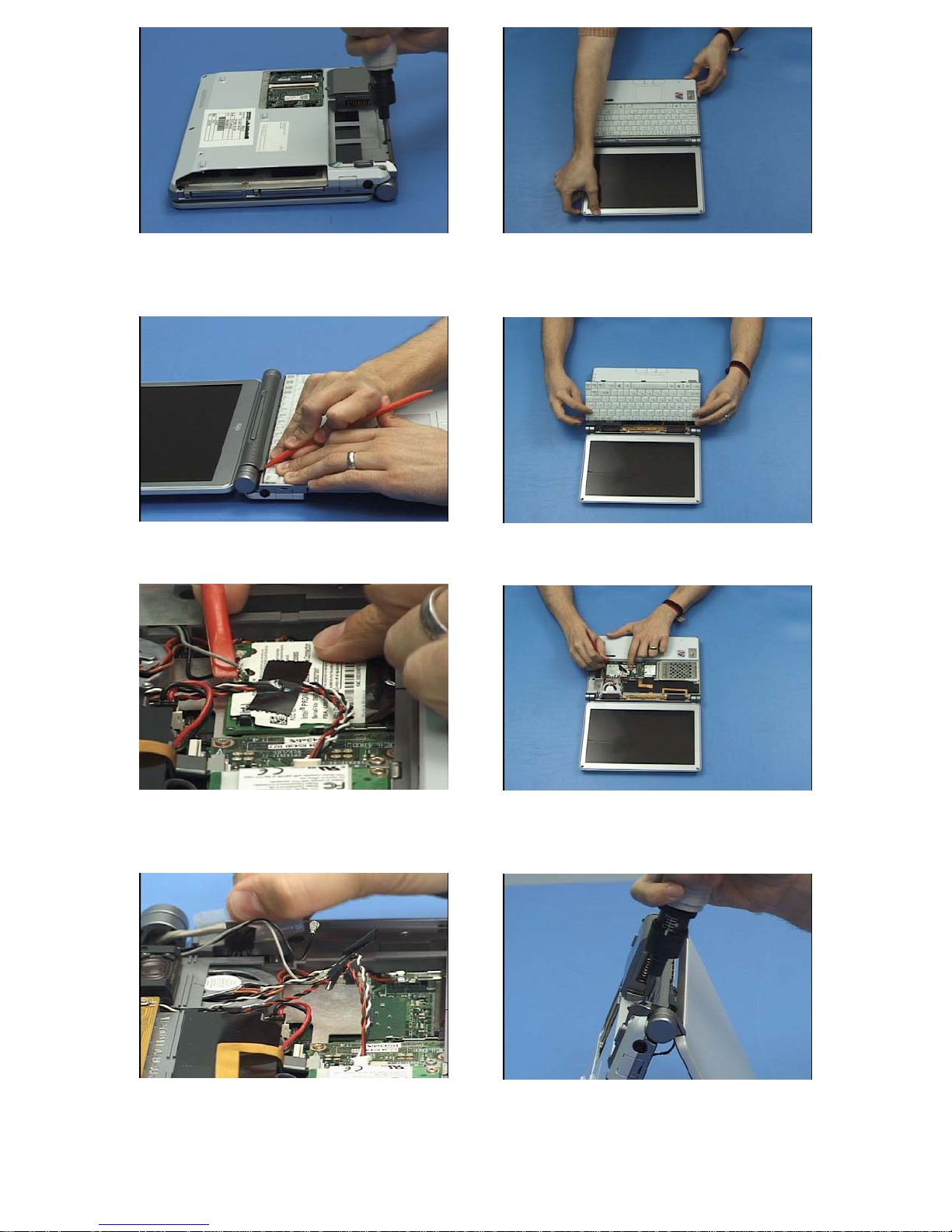
5. Remove all 8 screws from the
lower case.
6. Turn the unit over, open the cover
and lay it flat.
7. Using a plastic screwdriver, pry up
and remove the speaker/status LED
cover.
9. Disconnect the 2 antenna cables
from the WLAN card, disconnect the
speaker cable and un-tape it from
the top of the card.
8. Tilt up the keyboard, slide it
forward to release it, disconnect its
cable and remove it.
10. Remove the WLAN card by
pressing outward on the locking
clips.
11. Lift up the adhesive backed wire
guide, disconnect the display cable
and free it and the antenna cables
from underneath.
12. Turn the unit up on its front and
remove 2 screws from the rear of the
case.
Page 3

13. Lift off the display and set it
aside.
14. Use the plastic screwdriver to pry
off the palm rest
15. Disconnect the GlidePoint cable.
17. Remove 1 screw from the
GlidePoint bracket, lift it out and lift
out the GlidePoint sensor and button
board.
16. Turn the palm rest over and
disconnect and remove the
GlidePoint cable.
18. Lift up the Hard Disk Drive,
disconnect its cable and remove it.
19. Disconnect the key lock LED
cable, remove the tape from it and
remove the LED board.
20. Remove 3 screws from the
modem, disconnect the RJ11 cable
from it and remove it.
Page 4

21. Remove 13 screws from the
upper cover.
22. Disconnect the status LED cable,
remove the screw from underneath.
23. Lift off the top cover.
25. Remove 1 screw from the left
speaker and 2 from right and lift both
out.
24. Remove 1 screw from the hinge
switch, remove the tape from the
status LED cable and lift them out.
26. Disconnect the audio board’s
cable from the system board.
27. Remove 2 screws from the audio
board, un-tape the microphone
cable and remove them both.
28. Remove 2 screws from the
Expansion Card Daughterboard’s
cable and disconnect it.
Page 5

29. Lift out the Expansion Card
Daughterboard.
30. Extract 2 screws from the
PCMCIA bracket and remove it.
31. Remove 2 screws from the Bay
Daughterboard and pull it up to
disconnect it from the system board.
33. Disconnect the DC power cable
from the system board and lift it and
the connector out of the case.
32. Pry up the BIOS battery to
remove it from the case and
disconnect its cable.
34. Lift out the RJ11 connector and
cable.
35. Remove 2 hex screws from the
external VGA connector.
36. Remove 4 screws from the
system board and lift it out.
Page 6

37. Remove 2 screws from the CPU
fan/heat sink, disconnect its cable
and remove it.
38. Turn the system board over,
remove 2 screws from the Expansion
Card Daughterboard cable and
remove it.
39. Remove 1 screw from the Bay
shield and remove it.
41. Remove 2 screw covers from the
front of the Display and the 2 screws
underneath.
40. Stand the display on its top and
remove 2 screws from the bottom.
42. Pry around the perimeter of
cover to remove it. Be careful of
tape holding the cover to the LCD
along the top and bottom edges.
43. Pry up the inverter with the
plastic screwdriver.
44. Disconnect the power cable
and backlight cable from the
inverter.
Page 7

45. Remove 4 screws from the LCD
and tilt it up.
46. Remove the tape from cable
and disconnect it.
47. Route the antenna cables out of
the hinge cover.
49. Remove 2 screws from each of
the 2 hinges and lift them out.
48. Remove one screw from each of
the 2 antennas, remove them, and
disconnect their cables.
50. Pry the hinge cover off of the
right hinge with the plastic
screwdriver and remove the Display
cable from it.
 Loading...