

Page 1

Copyright
Copyright
Fujitsu PC Corporation has made every effort to ensure
the accuracy and completeness of this document.
However, as ongoing development efforts are continually improving the capabilities of our products, we
cannot guarantee the accuracy of the contents of this
document. We disclaim liability for errors, omissions,
or future changes.
Fujitsu and the Fujitsu logo are registered trademarks
and LifeBook is a trademark of Fujitsu Limited.
Intel and Pentiumare registered trademarks and
Centrino is a trademark of Intel Corporation or its
subsidiaries in the United States and other countries.
The following are registered trademarks of IBM
Corporation: IBM, IBM PC AT, IBM PS/2.
The following are registered trademarks of Microsoft
Corporation: MS, MS-DOS, Windows.
PCMCIA is a trademark of the Personal Computer
Memory Card International Association.
Earthlink is a registered trademark of EarthLink
Network, Inc.
Memory Stick, Memory Stick Duo, and MagicGate are
trademarks or registered trademarks of Sony Corporation and/or its affiliates.
Adobe Acrobat Reader is a registered trademark of
Adobe Systems, Inc.
Netscape 7.0 is a registered trademark of Netscape
Communications Corporation.
PowerQuest and Drive Image are registered trademarks
of PowerQuest Corporation.
InterVideo and WinDVD are trademarks of Intervideo,
Inc.
Realtek is a trademark of Realtek Semiconductor Corporation.
McAfee is a registered trademark of Network Associates/
McAfee.com Inc.
The DVD player found in some models of the LifeBook
notebook incorporates copyright protection technology
that is protected by method claims of certain U.S.
patents and other intellectual property rights owned by
Macrovision Corporation and other rights users. Use of
this copyright protection technology must be authorized
by Macrovision Corporation, and is intended for home
and other limited viewing uses only unless authorized by
Macrovision Corporation. Reverse engineering or disassembly is prohibited.
Dolby Headphone manufactured under license from
Dolby Laboratories. Dolby is a registered trademark and
Pro Logic and the double-D symbol are trademarks of
Dolby Laboratories. Copyrights 1992-1999 Dolby Laboratories. All rights reserved.
All other trademarks mentioned herein are the property
of their respective owners.
© Copyright 2003 Fujitsu PC Corporation. All rights
reserved. No part of this publication may be copied,
reproduced, or translated, without prior written consent
of Fujitsu PC Corporation. No part of this publication
may be stored or transmitted in any electronic form
without the written consent of Fujitsu PC Corporation.
B5FH-8471-01EN-00
DECLARATION OF CONFORMITY
according to FCC Part 15
Responsible Party Name: Fujitsu PC Corporation
Address: 5200 Patrick Henry Drive
Santa Clara, CA 95054
Telephone: (408) 982-9500
Declares that product: Base Model Configurations:
This device complies with Part 15 of the FCC rules. Operations are subject to the following two conditions:
(1) This device must not be allowed to cause harmful interference, (2) This device must accept any
interference received, including interference that may cause undesired operation.
LifeBook P5010 notebook
LifeBook P5010D notebook
Complies with Part 15 of the FCC Rules.
Page 2

LifeBook P5000 Notebook
Page 3

Table of Contents
Fujitsu LifeBook P5000 Notebook
Table of Contents
1
PREFACE
Preface
About This Guide . . . . . . . . . . . . . . . . . . . . . . . . .1
Fujitsu Contact Information . . . . . . . . . . . . . . . . .1
Warranty . . . . . . . . . . . . . . . . . . . . . . . . . . . . . . .1
2
GETTING TO KNOW YOUR
LIFEBOOK NOTEBOOK
Overview
Unpacking . . . . . . . . . . . . . . . . . . . . . . . . . . . . . .5
Locating the Controls
and Connectors
Top and Front Components . . . . . . . . . . . . . . . . .6
Left-Side Panel Components . . . . . . . . . . . . . . . .8
Right-Side Panel Components . . . . . . . . . . . . . . .9
Bottom Components . . . . . . . . . . . . . . . . . . . . .10
Keyboard
Using the Keyboard . . . . . . . . . . . . . . . . . . . . . .13
Numeric Keypad. . . . . . . . . . . . . . . . . . . . . . . . .13
Windows Keys . . . . . . . . . . . . . . . . . . . . . . . . . .13
Cursor Keys . . . . . . . . . . . . . . . . . . . . . . . . . . . .13
Function Keys. . . . . . . . . . . . . . . . . . . . . . . . . . .14
Touchpad Pointing Device
Clicking . . . . . . . . . . . . . . . . . . . . . . . . . . . . . . .15
Double-Clicking . . . . . . . . . . . . . . . . . . . . . . . . .15
Dragging . . . . . . . . . . . . . . . . . . . . . . . . . . . . . .15
Scrolling . . . . . . . . . . . . . . . . . . . . . . . . . . . . . . .16
Touchpad Control Adjustment . . . . . . . . . . . . . .16
Volume Control
Controlling the Volume . . . . . . . . . . . . . . . . . . .17
Flexible Bay Devices
Removing and Installing Modular Devices . . . . .18
3
GETTING STARTED WITH YOUR
LIFEBOOK NOTEBOOK
Status Indicator Panel
Power Indicator . . . . . . . . . . . . . . . . . . . . . . . . .11
DC-in Indicator. . . . . . . . . . . . . . . . . . . . . . . . . .11
Battery Level Indicators . . . . . . . . . . . . . . . . . . .11
Battery Charging Indicator . . . . . . . . . . . . . . . . .12
DVD/CD-RW Drive Access Indicator . . . . . . . . .12
Hard Drive or Removable
Media Drive Access Indicator . . . . . . . . . . . .12
PC/CF Card Access Indicator . . . . . . . . . . . . . . .12
Numeric Lock Indicator. . . . . . . . . . . . . . . . . . . .12
Caps Lock Indicator . . . . . . . . . . . . . . . . . . . . . .12
Scroll Lock Indicator . . . . . . . . . . . . . . . . . . . . . .12
Power Sources
Connecting the Power Adapters. . . . . . . . . . . . .23
Display Panel
Opening the Display Panel . . . . . . . . . . . . . . . . .24
Adjusting Display Panel Brightness . . . . . . . . . . .24
Closing the Display Panel . . . . . . . . . . . . . . . . . .24
Starting Your LifeBook Notebook
Power On. . . . . . . . . . . . . . . . . . . . . . . . . . . . . .25
Boot Sequence . . . . . . . . . . . . . . . . . . . . . . . . . .25
BIOS Setup Utility. . . . . . . . . . . . . . . . . . . . . . . .25
Booting the System . . . . . . . . . . . . . . . . . . . . . .26
Registering Your LifeBook notebook. . . . . . . . . .26
Installing Click Me!. . . . . . . . . . . . . . . . . . . . . . .26
Page 4

LifeBook P5000 Notebook
Power Management
Power/Suspend/Resume Button. . . . . . . . . . . . .27
Suspend Mode. . . . . . . . . . . . . . . . . . . . . . . . . .27
Hibernation Feature . . . . . . . . . . . . . . . . . . . . . .27
Display Timeout. . . . . . . . . . . . . . . . . . . . . . . . .28
Hard Disk Timeout. . . . . . . . . . . . . . . . . . . . . . .28
Windows Power Management. . . . . . . . . . . . . .28
Restarting the System. . . . . . . . . . . . . . . . . . . . .28
Power Off . . . . . . . . . . . . . . . . . . . . . . . . . . . . .28
4
USER-INSTALLABLE FEATURES
Lithium ion Battery
Recharging the Batteries. . . . . . . . . . . . . . . . . . . 31
Replacing the Battery. . . . . . . . . . . . . . . . . . . . . 32
External Floppy Disk Drive
Loading a Disk . . . . . . . . . . . . . . . . . . . . . . . . . .33
Ejecting a Disk . . . . . . . . . . . . . . . . . . . . . . . . . . 33
Preparing a Disk for Use. . . . . . . . . . . . . . . . . . . 33
Memory Upgrade Module
Accessing the Memory COmpartment . . . . . . . . 42
Removing a Memory Module . . . . . . . . . . . . . . 43
Installing a Memory Module . . . . . . . . . . . . . . . 43
Checking the Computer Recognition
of New Memory Capacity . . . . . . . . . . . . . . 43
Device Ports
Modem (RJ-11) Telephone Jack. . . . . . . . . . . . . 45
Internal LAN (RJ-45) Jack. . . . . . . . . . . . . . . . . . 45
IEEE 1394 Port. . . . . . . . . . . . . . . . . . . . . . . . . . 45
S-Video Out Port (TV Out) . . . . . . . . . . . . . . . . 45
Universal Serial Bus Ports . . . . . . . . . . . . . . . . . . 46
Headphone Jack . . . . . . . . . . . . . . . . . . . . . . . . 46
Microphone Jack . . . . . . . . . . . . . . . . . . . . . . . . 46
Mini-VGA Port. . . . . . . . . . . . . . . . . . . . . . . . . . 46
Optical Digital Audio Connector . . . . . . . . . . . . 46
5
WIRELESS LAN USER’S GUIDE
FCC Regulatory Information . . . . . . . . . . . . . . . 51
DVD/CD-RW Combo Drive
DVD/CD-RW Combo Drive Software . . . . . . . .34
Loading a DVD, CD, CD-R, or CD-RW . . . . . . .34
Removing Media . . . . . . . . . . . . . . . . . . . . . . . . 35
Using the DVD/CD-RW Drive Software. . . . . . . 35
Using DolbyTM Headphone. . . . . . . . . . . . . . . .35
Using DVD/CD-RW Drive on Battery Power . . . 36
Auto Insert Notification Function . . . . . . . . . . . .36
PC Cards
Installing PC Cards. . . . . . . . . . . . . . . . . . . . . . . 37
Removing PC Cards . . . . . . . . . . . . . . . . . . . . . . 37
CF Cards
Installing CF Cards . . . . . . . . . . . . . . . . . . . . . . .38
Removing CF Cards . . . . . . . . . . . . . . . . . . . . . . 39
Memory Stick/Secure Digital Slot
Installing Memory Stick/SD Cards . . . . . . . . . . . 40
Removing A Memory Stick/SD Card . . . . . . . . . 41
Before Using the Wireless LAN
For better communications . . . . . . . . . . . . . . . . 53
Stopping transmission . . . . . . . . . . . . . . . . . . . . 54
Starting Transmission. . . . . . . . . . . . . . . . . . . . . 54
Connection using Windows XP
Flow of operations. . . . . . . . . . . . . . . . . . . . . . . 55
Preparation for wireless LAN connection . . . . . . 55
Connection to the network . . . . . . . . . . . . . . . . 57
Connection using Windows 2000
Flow of operations. . . . . . . . . . . . . . . . . . . . . . . 61
Preparation for wireless LAN connection . . . . . . 61
Connection to the network . . . . . . . . . . . . . . . . 63
Other settings
Setting of power-saving function. . . . . . . . . . . . 67
Troubleshooting
Troubleshooting. . . . . . . . . . . . . . . . . . . . . . . . . 68
Page 5

Table of Contents
Wireless LAN Glossary
Glossary . . . . . . . . . . . . . . . . . . . . . . . . . . . . . . .71
IP address information
IP Addresses. . . . . . . . . . . . . . . . . . . . . . . . . . . .73
Wireless LAN Specifications
Specifications . . . . . . . . . . . . . . . . . . . . . . . . . . .74
6
TROUBLESHOOTING YOUR
LIFEBOOK NOTEBOOK
Troubleshooting
Identifying the Problem . . . . . . . . . . . . . . . . . . .77
Specific Problems . . . . . . . . . . . . . . . . . . . . . . . .77
Troubleshooting Table . . . . . . . . . . . . . . . . . . . .78
Power On Self Test Messages. . . . . . . . . . . . . . .86
Emergency DVD Tray Release . . . . . . . . . . . . . .87
Modem Result Codes. . . . . . . . . . . . . . . . . . . . .87
Restoring Your Pre-installed Software
Drive Image Special Edition (DISE) . . . . . . . . . . .88
8
SYSTEM SPECIFICATIONS
Specifications
Configuration Label . . . . . . . . . . . . . . . . . . . . . .99
Microprocessor. . . . . . . . . . . . . . . . . . . . . . . . . .99
Memory . . . . . . . . . . . . . . . . . . . . . . . . . . . . . . .99
Video . . . . . . . . . . . . . . . . . . . . . . . . . . . . . . . . .99
Audio . . . . . . . . . . . . . . . . . . . . . . . . . . . . . . . . .99
Mass Storage Device Options. . . . . . . . . . . . . . .99
Features . . . . . . . . . . . . . . . . . . . . . . . . . . . . . . .99
Device Ports . . . . . . . . . . . . . . . . . . . . . . . . . . .100
Keyboard . . . . . . . . . . . . . . . . . . . . . . . . . . . . .100
Power. . . . . . . . . . . . . . . . . . . . . . . . . . . . . . . .100
Dimensions and Weight . . . . . . . . . . . . . . . . . .100
Environmental Requirements . . . . . . . . . . . . . .100
Popular Accessories . . . . . . . . . . . . . . . . . . . . .100
Pre-Installed Software . . . . . . . . . . . . . . . . . . .101
Learning About Your Application Software. . . .101
Windows XP Software Only . . . . . . . . . . . . . . .101
Windows 2000 Software Only . . . . . . . . . . . . .101
Regulatory Information . . . . . . . . . . . . . . . . . .103
Notice . . . . . . . . . . . . . . . . . . . . . . . . . . . . . . .103
7
CARING FOR YOUR
LIFEBOOK NOTEBOOK
Care and Maintenance
Batteries . . . . . . . . . . . . . . . . . . . . . . . . . . . . . . .94
Floppy Disks and Drives . . . . . . . . . . . . . . . . . . .94
Media Care . . . . . . . . . . . . . . . . . . . . . . . . . . . .95
PC Cards . . . . . . . . . . . . . . . . . . . . . . . . . . . . . .95
9
GLOSSARY & INDEX
Glossary . . . . . . . . . . . . . . . . . . . . . . . . . . . . . .109
Index . . . . . . . . . . . . . . . . . . . . . . . . . . . . . . . .113
Page 6

LifeBook P5000 Notebook
Page 7

1
Preface
Page 8

LifeBook P5000 Notebook
Page 9

Preface
Preface
ABOUT THIS GUIDE
The LifeBook P5000/P5000D Series notebook is a
completely self-contained unit with an active-matrix
(TFT) color LCD display. It has a powerful interface that
enables it to support a variety of optional features.
The LifeBook P Series notebook from Fujitsu PC Corporation is a small but powerful computer. It is powered
by a Mobile Intel Pentium M processor, has a built-in
color display, and brings the functionality of desktop
personal computers (PCs) to a portable environment.
This manual explains how to operate your LifeBook
notebook’s hardware and built-in system software. Your
notebook is compatible with the IBM® PC AT.
It comes with Microsoft Windows® 2000, Windows XP
Home, or Window XP Pro pre-installed.
Conventions Used in the Guide
Keyboard keys and on-screen buttons appear in
brackets. Example: [Fn], [F1], [ESC], and [CTRL].
Pages with additional information about a specific topic
are cross-referenced within the text.
Example: (See page xx.)
DOS commands you enter appear in Courier type.
Example: Shutdown the computer?
POINT
The point icon highlights information that will enhance
your understanding of the subject material.
CAUTION
The caution icon highlights information that is
important to the safe operation of your computer, or to
the integrity of your files. Please read all caution
information carefully.
FUJITSU CONTACT INFORMATION
Service and Support
You can contact Fujitsu Service and Support in the
following ways:
■
Toll free: 1-800-8Fujitsu (1-800-838-5487)
■
Fax: 1-901-259-5700
■
E-mail: 8fujitsu@fujitsupc.com
■
Web site: http://www.fujitsupc.com
Before you place the call, you should have the
following information ready so that the customer
support representative can provide you with the
fastest possible solution:
■
Product name
■
Product configuration number
■
Product serial number
■
Purchase date
■
Conditions under which the problem occurred
■
Any error messages that have occurred
■
Hardware configuration
■
Type of device connected, if any
Fujitsu Online
You can go directly to the online Fujitsu Product catalog
for your LifeBook notebook by clicking on the LifeBook
Accessories Web site URL link, located in the Windows
Start menu.
You can also reach Fujitsu Service and Support online by
clicking on the Fujitsu Service and Support Web site
URL link, located in the Service and Support Software
folder of the Windows Start menu.
POINT
You must have an active internet connection to
use the online URL links.
WARRANTY
Your LifeBook notebook is backed by a one year
International Limited Warranty. Check the service kit
that came with your notebook for warranty terms and
conditions.
WARNING
The warning icon highlights information that can be
hazardous to you, your LifeBook notebook, or your
files. Please read all warning information carefully.
1
Page 10

LifeBook P5000 Notebook – Section One
2
Page 11

2
Getting to Know
Your LifeBook Notebook
3
Page 12

LifeBook P5000 Notebook – Section Two
4
Page 13
Getting to Know Your LifeBook
Figure 2-1 Fujitsu LifeBook P5000 notebook
Overview
This section describes the components of your Fujitsu
LifeBook P5000 notebook. We strongly recommend that
you read it before using your notebook – even if you are
already familiar with notebook computers.
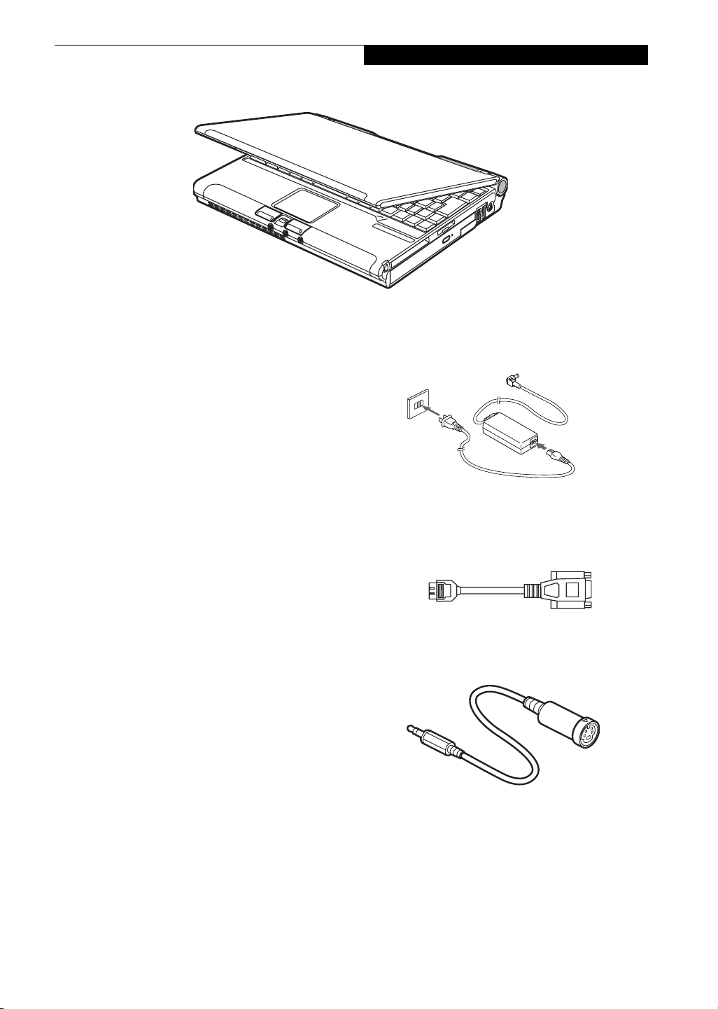
UNPACKING
When you receive your LifeBook notebook, unpack it
carefully, and compare the parts you have received with
the items listed below.
■
LifeBook P5000 notebook(Figure 2-1)
■
AC adapter with AC power cord (Figure 2-2)
■
Lithium ion battery
■
Weight Saver
■
Phone/Modem (RJ-11) telephone cable
■
Mini-VGA cable (Figure 2-3)
■
Mini S-Video Cable Adapter (Figure 2-4)
■
Driver and Application Restore CD
■
Getting Started Guide
■
User’s Guide (this document)
■
International Limited Warranty Brochure
■
Certification of Authenticity with operating system
manual.
■
Premium Care registration card and envelope
Depending upon the configuration of your system, one
or more of the following items may also be included:
■
Modular DVD/CD-RW combo drive
■
External Floppy Disk Drive
■
Modular 2nd battery
■
Additional battery
■
DVD Application CD
■
CD-RW Application CD
Once you have checked and confirmed that your LifeBook system is complete, read through the following
pages to learn about all of your notebook’s components.
Figure 2-2 AC Adapter
Figure 2-3 Mini-VGA Cable
Figure 2-4 Mini S-Video Cable Adapter
5
Page 14
LifeBook P5000 Notebook – Section Two
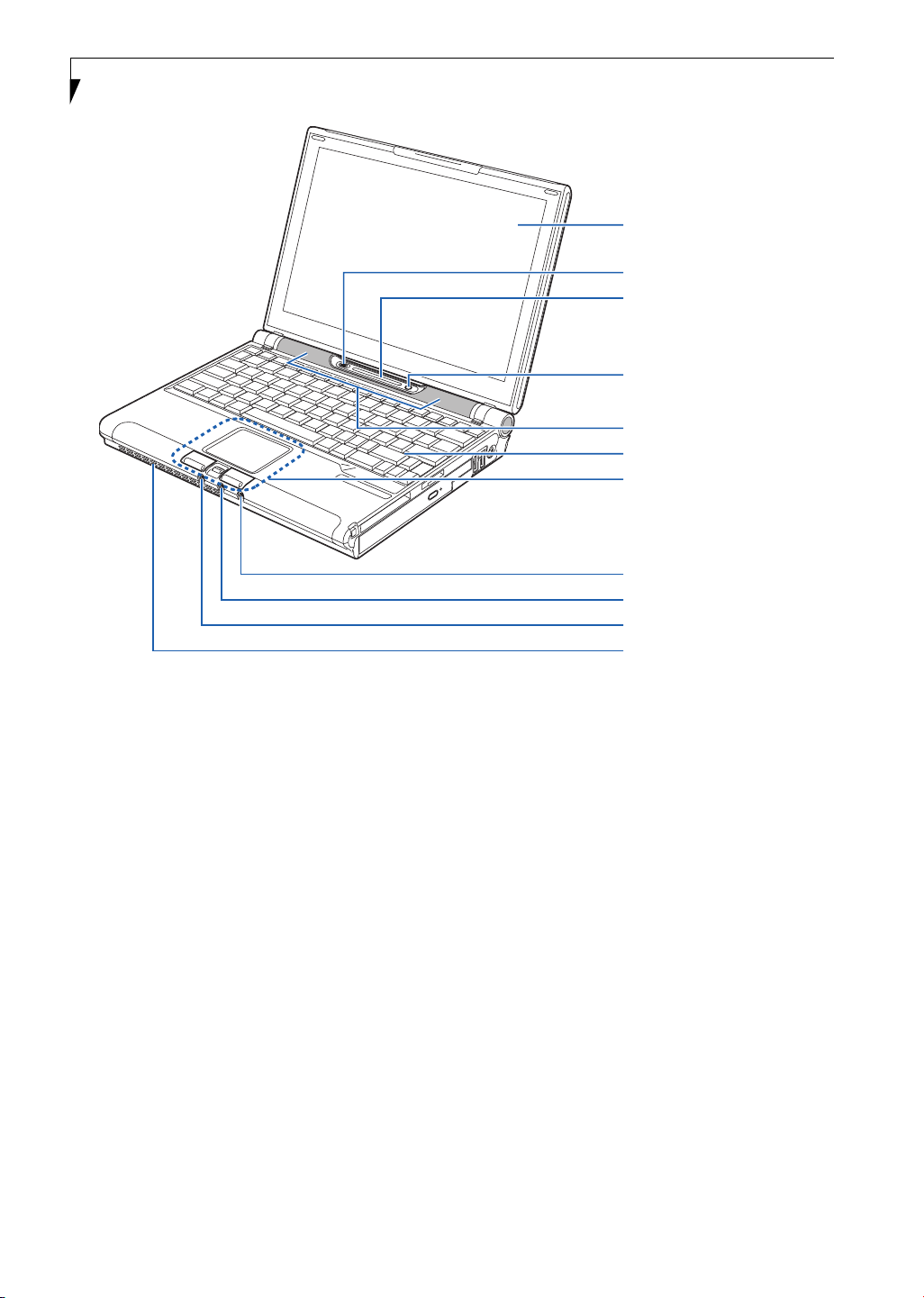
Figure 2-5 LifeBook notebook with display open
Display Panel
Wireless LAN On/Off Switch
Status Indicator Panel
Suspend/Resume/
Power On Button
Stereo Speaker
Keyboard
Touch Panel Pointing Device
Mini S-Video Jack
Microphone Jack
Headphone/Optical Digital
Audio Jack
Air Vents
Locating the Controls
and Connectors
TOP AND FRONT COMPONENTS
The following is a brief description of your LifeBook
notebook’s top and front components.
Display Panel
The display panel is a color LCD panel with back
lighting for the display of text and graphics.
Wireless LAN On/Off Switch
Allows you to turn the optional Wireless LAN device on
and off. Note that this switch is present on all models of
the LifeBook P5000 notebook, but it is functional only
on those with an optional Wireless LAN installed.
Status Indicator Panel
The Status Indicator Panel displays symbols that correspond with a specific component of your LifeBook notebook. (See Status Indicator Panel on page 11 for more
information)
Suspend/Resume/Power On Button
The Suspend/Resume/Power On button allows you to
suspend notebook activity without powering off, resume
your LifeBook notebook from suspend mode, and
power on your notebook when it has been shut down
from Windows. (See Power/Suspend/Resume Button on
page 27 for more information)
Stereo Speakers
The built-in dual box speakers allow for stereo sound.
Keyboard
A full-size keyboard with dedicated Windows
keys. (See Keyboard on page 13 for more information)
Touchpad Pointing Device/Scroll Button
The Touchpad pointing device is a mouse-like cursor
control with three buttons (left, right, and scroll
button). (See Touchpad Pointing Device on page 15 for
more information)
Mini S-Video Out Jack
The S-video output jack is used to transmit a higher
resolution video signal to a compatible TV or VCR. A
mini S-Video cable adapter is included with your system.
(See S-Video Out Port (TV Out) on page 45 for more
information)
6
Page 15

Microphone Jack
The microphone jack allows you to connect an external
mono microphone. (See Microphone Jack on page 46 for
more information)
Headphone/Optical Digital Audio Jack
The headphone/optical digital audio jack allows you to
connect headphones or to download digital audio onto a
MiniDisc recorder’s SPDIF (Sony Philips Digital Interface) format. (See Optical Digital Audio Connector on
page 46 for more information)
Air Vents
The air vents allow for proper cooling of the system
while it is operating.
Getting to Know Your LifeBook
7
Page 16
LifeBook P5000 Notebook – Section Two
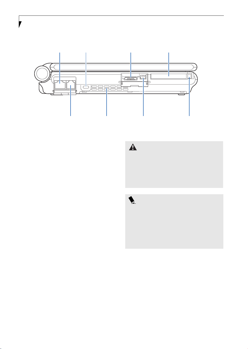
Anti-theft
LAN Port
Lock Slot Mini-VGA Jack
Compact Flash Slot
Modem Port
Air Vents
Figure 2-6 LifeBook notebook left-side panel
LEFT-SIDE PANEL COMPONENTS
The following is a brief description of your LifeBook
notebook’s left-side components.
LAN (RJ-45) Jack
The internal LAN (RJ-45) jack is used for an internal
Fast Ethernet (10/100 Base-TX) connection.
(See Internal LAN (RJ-45) Jack on page 45 for more information)
Anti-theft Lock Slot
The anti-theft lock slot allows you to attach an optional
physical lock down device.
Mini-VGA Jack
The mini-VGA jack allows you to connect your LifeBook
notebook to an external monitor with the mini-VGA
cable adapter included with your system. (See Mini-VGA
Port on page 46 for more information)
Compact Flash Card Slot
Allows you to insert a compact flash (CF) card. (See CF
Cards on page 38 for more information)
Modem (RJ-11) Telephone Port
The Modem (RJ-11) telephone jack is for attaching
a telephone line to the internal multinational 56K
modem. (See Modem (RJ-11) Telephone Jack on page 45
for more information)
IEEE 1394 Jack
Compact Flash
Card Eject Button
WARNING
The internal modem is not intended for use with Digital
PBX systems. Do not connect the internal modem to a
Digital PBX as it may cause serious damage to the
internal modem or your entire notebook. Consult your
PBX manufacturer’s documentation for details. Some
hotels have Digital PBX systems. Be sure to find out
BEFORE you connect your modem.
POINT
The internal multinational modem is designed to the
ITU-T V.90 standard. Its maximum speed of 53000bps
is the highest allowed by FCC, and its actual connection
rate depends on the line conditions. The maximum
speed is 33600bps at upload.
For additional information about the multinational
modem, refer to the Fujitsu web site at:
www.fujitsupc.com/modems
Air Vents
The air vents allow for proper cooling of the system
while it is operating.
IEEE 1394 Jack
The IEEE 1394 jack (also known as “Firewire”) is used to
connect between your LifeBook and a peripheral such as
a digital video camera.(See IEEE 1394 Port on page 45 for
more information)
Compact Flash Card Eject Button
Allows you to eject a compact flash card. (See Removing
CF Cards on page 39 for more information)
8
Page 17

Getting to Know Your LifeBook
PC Card
Eject Button
PC Card Flexible Bay
Slot
Figure 2-7 LifeBook notebook right-side panel
Memory Stick/
SD Card Slot
RIGHT-SIDE PANEL COMPONENTS
The following is a brief description of your LifeBook
notebook’s right-side components.
PC Card Eject Button
The PC Card eject button allows you to remove PC
Cards from the PC Card slot. (See PC Cards on page 37
for more information)
PC Card Slots
The PC Card Slot allows you to install one Type II PC
Card. (See PC Cards on page 37 for more information)
Flexible Bay
The Flexible Bay can accommodate either the standard
DVD/CD-RW Drive or an optional modular bay battery.
If neither device is installed, the weight saver should be
installed. (See Flexible Bay Devices on page 18 for more
information)
Memory Stick/SD Card Slot
The Memory Stick/Secure Digital (SD) card slot allows
you to install a flash memory card for data storage. This
architecture allows you to transfer data between a variety
of different digital devices. (See Installing Memory Stick/
SD Cards on page 42 for more information)
USB 2.0 Ports
The USB ports allow you to connect Universal Serial Bus
2.0 devices. (See Universal Serial Bus Ports on page 46 for
more information)
DC Power Jack
The DC power jack allows you to plug in the AC adapter
or the optional Auto/Airline adapter to power your notebook and charge the internal Lithium ion battery.
USB Ports DC Power Jack
9
Page 18
LifeBook P5000 Notebook – Section Two
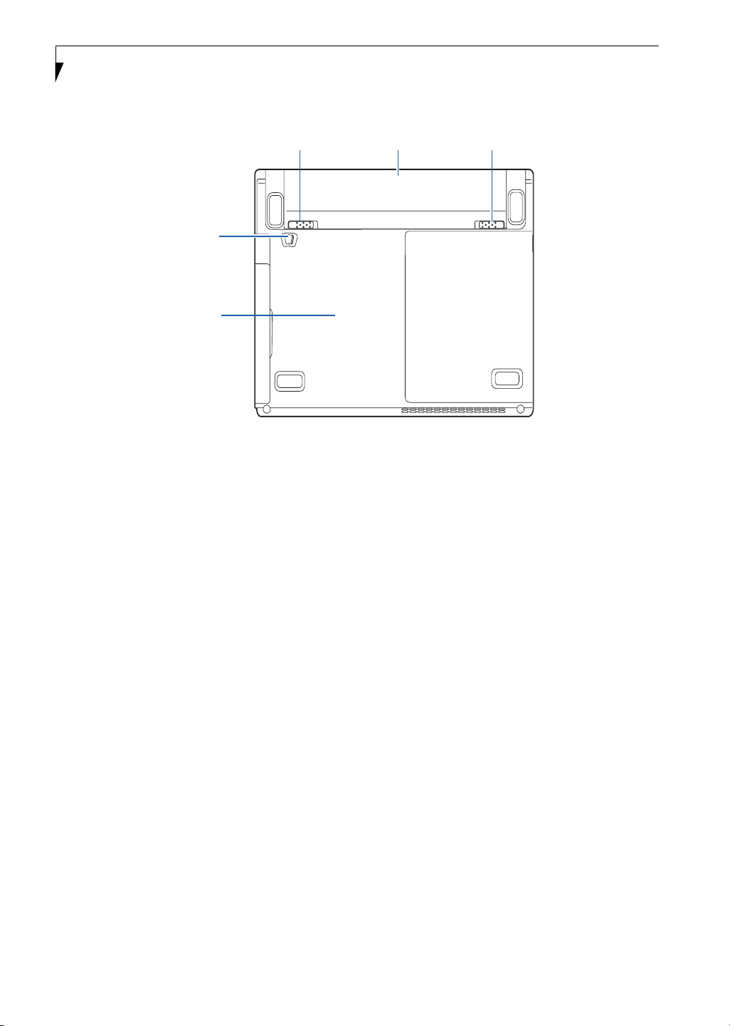
Battery
Release
Latch
Flexible Bay
Release Latch
Main Unit and
Configuration Label
Figure 2-8 LifeBook notebook bottom panel
BOTTOM COMPONENTS
The following is a brief description of your LifeBook
notebook’s bottom panel components.
Lithium ion Battery
The internal Lithium ion battery can be installed in the
battery bay by aligning it with the slides and pushing it
into place. The battery can be removed when swapping
with a charged battery, or when the computer is to be
stored for a long period of time. (See Lithium ion Battery
on page 31 for more information)
Lithium ion Battery
Battery
Release
Latch
Battery Release Latches
Slide the battery releases to unlatch the battery.
Flexible Bay Release Latch
The Flexible Bay Release Latch releases the flexible bay
device for removal. (See Removing and Installing
Modular Devices on page 18 for more information)
Main Unit and Configuration Label
The configuration label shows the model number and
other information about your LifeBook notebook. In
addition, the configuration portion of the label has the
serial number and manufacturer information that you
will need to give your support representative. It identifies the exact version of various components of your
notebook.
10
Page 19
Battery
Charging
Indicator
Getting to Know Your LifeBook
Power
DC-In
Battery Identifier/
Figure 2-9 Status Indicator Panel
DVD/CD-RW
Combo Drive
Access
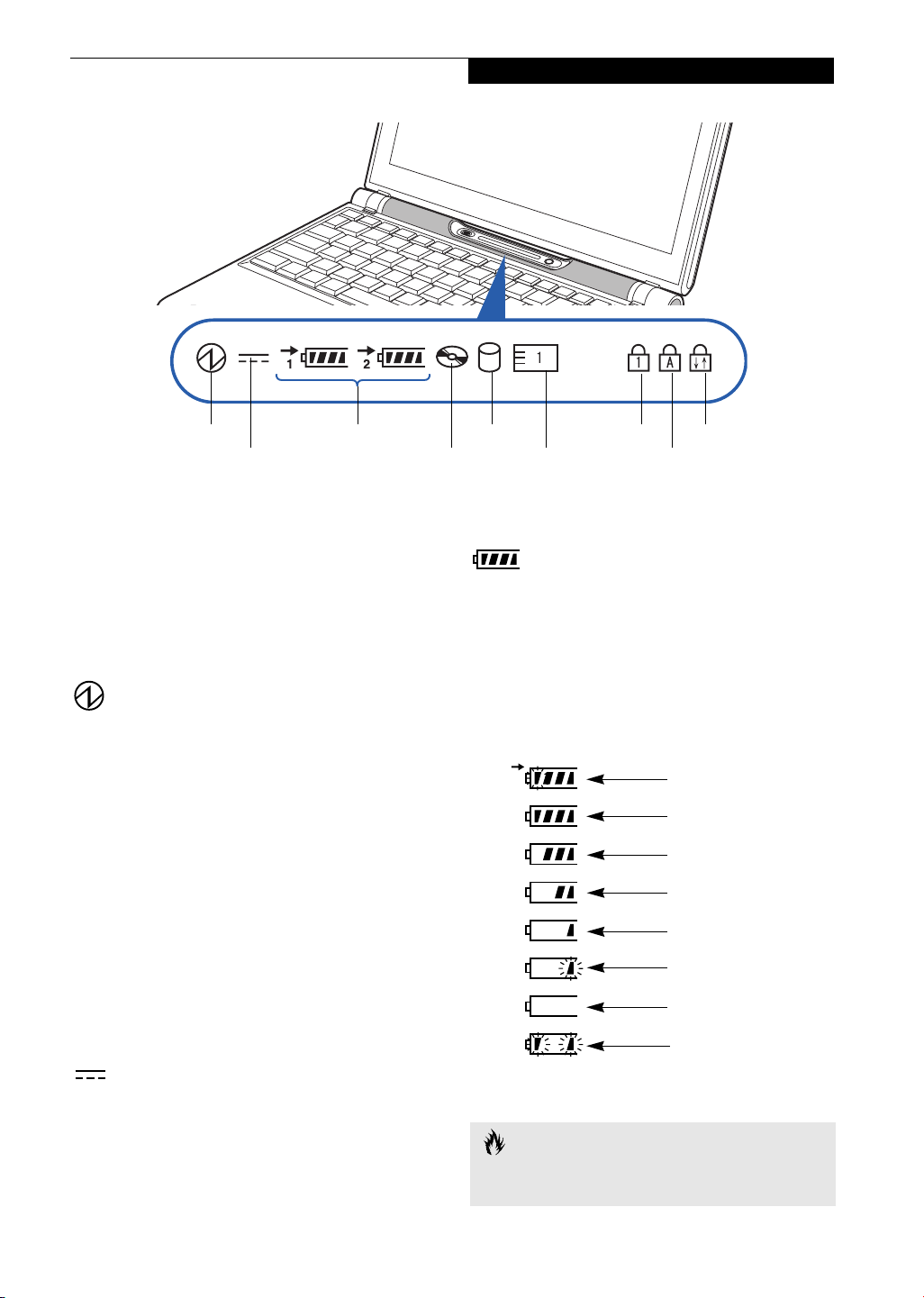
Status Indicator Panel
The Status Indicator displays symbols that correspond to
a specific component of your Fujitsu LifeBook notebook. These symbols tell you how each of those components are operating. (Figure 2-9)
POWER INDICATOR
The Power indicator symbol states whether your
system is operational. It has several different states,
each of which tells you what mode your notebook is
in at that time.
■
Steady On: This means that there is power to your
LifeBook notebook and that it is ready for use.
■
Flashing: This means that your LifeBook notebook is
in Suspend mode.
■
Steady Off: This means that your system is either in
Hibernation mode, or that your LifeBook notebook
has been turned off with the power switch.
If you are charging your battery, the Power indicator
symbol will remain on even if your notebook is shut off.
The Power indicator symbol will also remain on if you
have either adapter connected and are shut down from
Windows, but have not turned off the power switch.
Hard Drive
Access
PC/CF Card
Access
Numeric
LockBattery Level
Scroll Lock
Caps Lock
BATTERY LEVEL INDICATORS
The Battery Level indicators state whether or not the
primary Lithium ion battery and/or the optional second
Lithium ion battery are installed (Battery 1 refers to the
primary Lithium ion battery, while Battery 2 refers to the
Flexible Bay optional second battery). In addition, this
symbol states how much charge is available within each
installed battery. The symbol will only be displayed for a
battery that is currently installed in your LifeBook notebook. (Figure 2-10)
76%–100% Charging
76%–100%
51%–75%
26%–50%
11%–25%
Low Warning <11%
Critical Low or
Dead Battery
Shorted Battery
DC-IN INDICATOR
The DC-In indicator states that your notebook is
powered by an external source such as an AC adapter or
Auto/Airline adapter.
Figure 2-10 Battery Level Indicator
CAUTION
A shorted battery is damaged and must be replaced.
(Figure 2-10)
11
Page 20
LifeBook P5000 Notebook – Section Two
POINT
If there is no battery activity, the power adapters are not
connected, and the power switch is Off, the Battery
Level indicators will also be off.
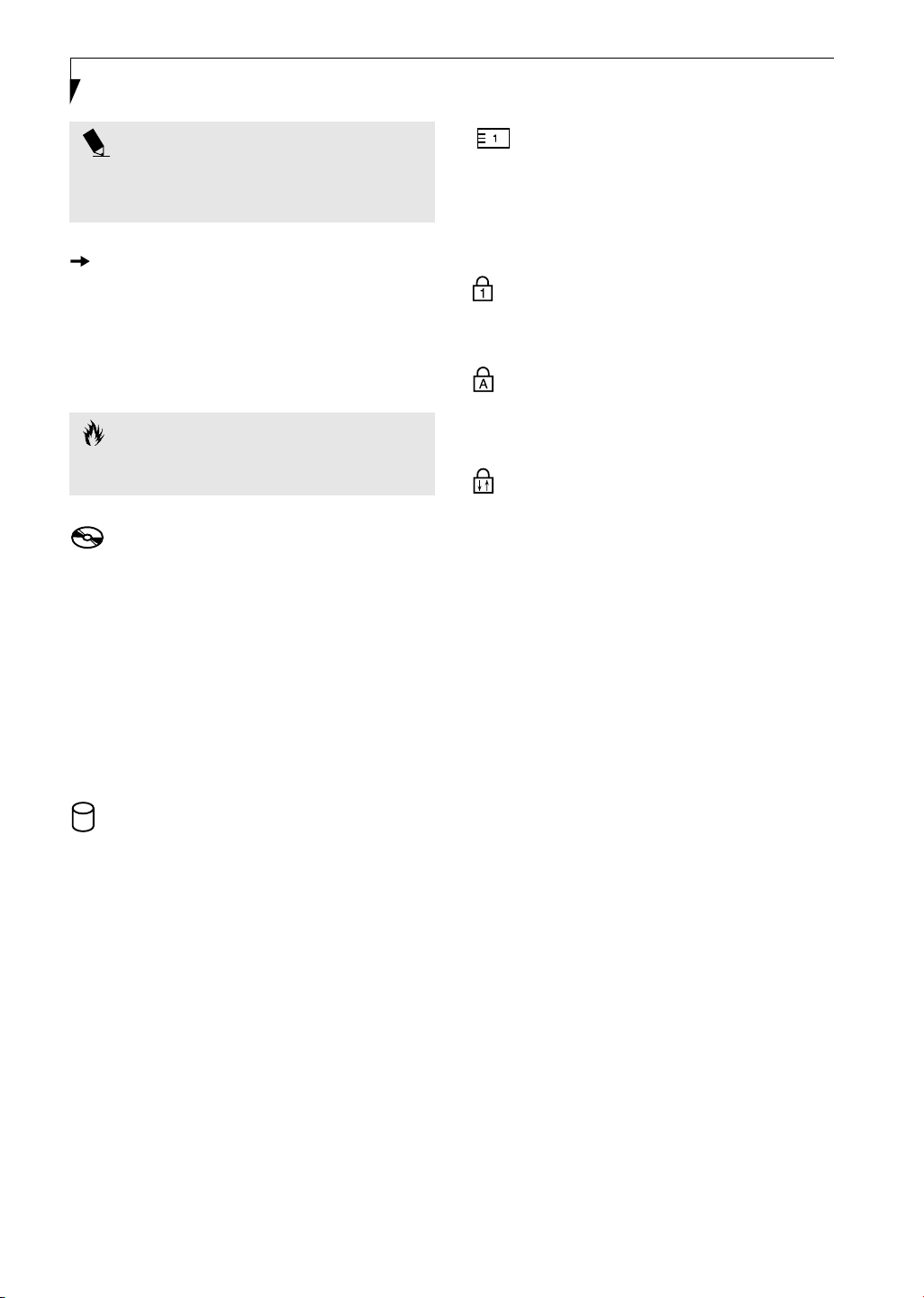
BATTERY CHARGING INDICATOR
Located to the left of the Battery Level indicator is a
small arrow symbol. This symbol indicates that the
battery is being charged by an external source. This indicator operates whether the power switch is in the On or
Off position, and will flash if the battery is too hot or
cold to charge.
CAUTION
Batteries subjected to shocks, vibration or extreme
temperatures can be permanently damaged.
DVD/CD-RW DRIVE
ACCESS INDICATOR
The DVD/CD-RW Access indicator tells you that the
DVD/CD-RW combo drive is being accessed. If the Auto
Insert Notification function is active, the indicator will
flash periodically when your system is checking the
DVD/CD-RW drive. If the Auto Insert Notification
function is not active, the indicator will only flash when
you access the DVD/CD-RW drive. The default setting is
the Auto Insert Notification function active. (See Auto
Insert Notification Function on page 36 for more information)
PC/CF CARD ACCESS INDICATOR
The PC/CF Card Access indicator states whether or not
your notebook is accessing a PC Card or a Compact
Flash (CF) Card. The indicator will flash if your software
tries to access a card, even if there is no card installed.
(See PC Cards on page 37 for more information)
NUMERIC LOCK INDICATOR
The Numeric Lock indicator states that the internal
keyboard is set in ten-key numeric keypad mode.
CAPS LOCK INDICATOR
The Caps Lock indicator states that your keyboard is set
to type in all capital letters.
SCROLL LOCK INDICATOR
The Scroll Lock indicator states that your scroll lock is
active.
HARD DRIVE OR REMOVABLE
MEDIA DRIVE ACCESS INDICATOR
The Hard Drive Access indicator states whether your
internal hard drive is being accessed.
12
Page 21
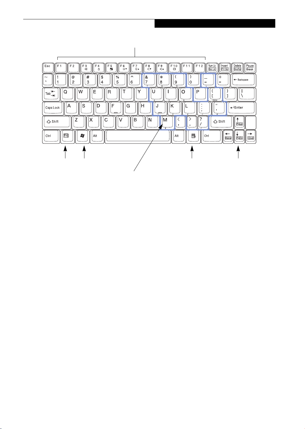
Function Keys
Getting to Know Your LifeBook
Fn Key
Windows
Start Key
Numeric Keypad
Figure 2-11 Keyboard
Keyboard
USING THE KEYBOARD
Your Fujitsu LifeBook notebook has an integral 83-key
keyboard. The keys perform all the standard functions of
a 101-key keyboard, including the Windows keys and
other special function keys. This section describes the
following keys. (Figure 2-11)
■
Numeric keypad: Your notebook allows certain keys to
serve dual purposes, both as standard characters and
as numeric and mathematical keys. The ability to toggle between the standard character and numerical keys
is controlled through the [NumLk] key.
■
Cursor keys: Your keyboard contains four arrow
keys for moving the cursor or insertion point to the
right, left, up, or down within windows, applications
and documents.
■
Function keys: The keys labeled [F1] through [F12],
are used in conjunction with the [Fn] key to produce
special actions that vary depending on what program
is running.
■
Windows keys: These keys work with your Windows
operating system and function the same as the
onscreen Start menu button, or the right button
on your pointing device.
Windows
Application Key
Cursor Keys
Turning off the NumLk feature is done the same way.
Once this feature is activated you can enter numerals 0
through 9, perform addition ( + ), subtraction ( - ),
multiplication ( * ), or division ( / ), and enter decimal
points ( . ) using the keys designated as ten-key function
keys. The keys in the numeric keypad are marked on the
front edge of the key to indicate their secondary functions.
(Figure 2-11)
WINDOWS KEYS
Your LifeBook notebook has two Windows keys,
consisting of a Start key and an Application key. The
Start key displays the Start menu. This button functions
the same as your onscreen Start menu button. The
Application key functions the same as your right mouse
button and displays shortcut menus for the selected
item. (Please refer to your Windows documentation for
additional information regarding the Windows keys.)
(Figure 2-11)
CURSOR KEYS
The cursor keys are the four arrow keys on the keyboard
which allow you to move the cursor up, down, left and
right in applications. In programs such as Windows
Explorer, it moves the “focus” (selects the next item up,
down, left, or right). (Figure 2-11)
NUMERIC KEYPAD
Certain keys on the keyboard perform dual functions as
both standard character keys and numeric keypad keys.
NumLk can be activated by pressing the [NumLk] keys.
13
Page 22

LifeBook P5000 Notebook – Section Two
FUNCTION KEYS
Your LifeBook notebook has 12 function keys, F1
through F12. The functions assigned to these keys differ
for each application. You should refer to your software
documentation to find out how these keys are used.
(Figure 2-11)
The [Fn] key provides extended functions for the
notebook and is always used in conjunction with
another key.
■
[Fn+F3]: Pressing [F3] while holding [Fn] will toggle
the Audio Mute on and off.
■
[Fn+F4]: Pressing [F4] while holding [Fn] will toggle
the Quick Point feature on and off. Note that the
[Fn+F4] combination only works if Manual Setting is
selected in the BIOS. (See “Entering the BIOS Setup
Utility” on page 25)
■
[Fn+F5]: Pressing [F5] while holding [Fn] allows
you to toggle between video compensation and no
compensation. (Video compensation controls spacing
on the display. When it is enabled, displays with less
than 1024 x 768 or 800 x 600 pixel resolution will still
cover the entire screen.)
■
[Fn+F6]: Pressing [F6] repeatedly while holding [Fn]
will lower the brightness of your display.*
■
[Fn+F7]: Pressing [F7] repeatedly while holding [Fn]
will increase the brightness of the display.*
■
[Fn+F8]: Pressing [F8] repeatedly while holding [Fn]
will decrease the volume of your LifeBook notebook.**
■
[Fn+F9]: Pressing [F9] repeatedly while holding [Fn]
will increase the volume of your LifeBook notebook.**
■
[Fn+F10]: Pressing [F10] while holding [Fn] allows
you to change your selection of where to send your
display video. Each time you press the combination
of keys you will step to the next choice. The choices,
in order, are: built-in display panel only, both built-in
display panel and external monitor or external
monitor only.
* There are eight brightness levels.
** There are 17 audio levels.
14
Page 23
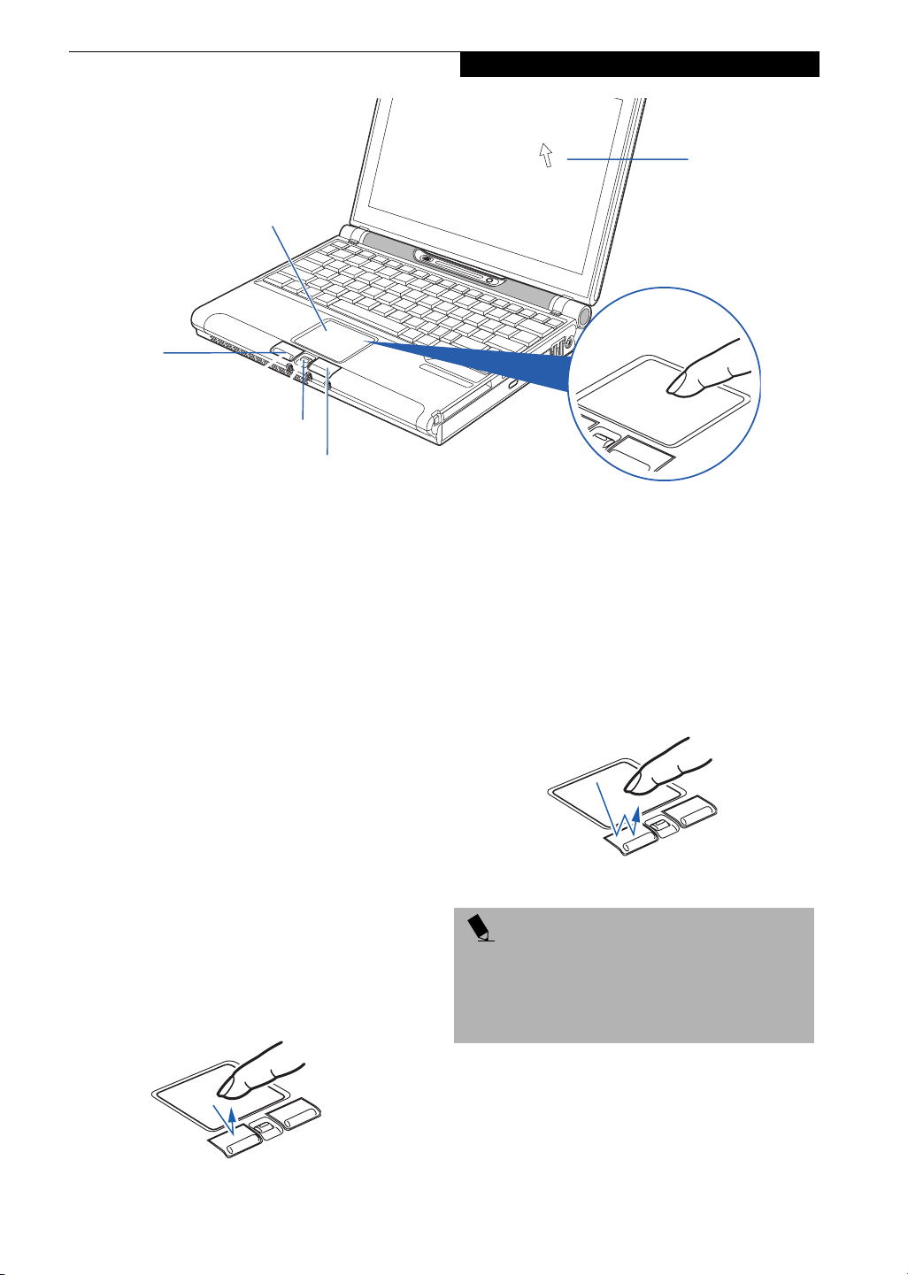
Left Button
Getting to Know Your LifeBook
Cursor
Cursor Control
Scroll Button
Right Button
Figure 2-12 Touchpad pointing device
Touchpad Pointing Device
The Touchpad pointing device comes built into your
LifeBook notebook. It is used to control the movement
of the pointer to select items on your display panel. The
Touchpad is composed of a cursor control, a left and
right button, and a scrolling button. The cursor control
works the same way a mouse does, and moves the cursor
around the display. It only requires light pressure with
the tip of your finger. The left and right buttons function
the same as mouse buttons. The actual functionality of
the buttons may vary depending on the application that
is being used. The scrolling button allows you to navigate quickly through pages, without having to use the
scroll bars. (Figure 2-16)
CLICKING
Clicking means pushing and releasing a button.
To left-click, move the cursor to the item you wish
to select, press the left button once, and then immediately release it. To right-click, move the mouse cursor to
the item you wish to select, press the right button once,
and then immediately release it. You also have the option
to perform the clicking operation by tapping lightly on
the Touchpad once. (Figure 2-13)
DOUBLE-CLICKING
Double-clicking means pushing and releasing the left
button twice in rapid succession. This procedure does
not function with the right button. To double-click,
move the cursor to the item you wish to select, press
the left button twice, and then immediately release it.
You also have the option to perform the double-click
operation by tapping lightly on the Touchpad twice.
(Figure 2-14)
Figure 2-14 Double-clicking
POINT
■
If the interval between clicks is too long, the
double-click will not be executed.
■
Parameters for the Touchpad can be adjusted from
the Mouse Properties dialog box located in the
Windows Control Panel.
Figure 2-13 Clicking
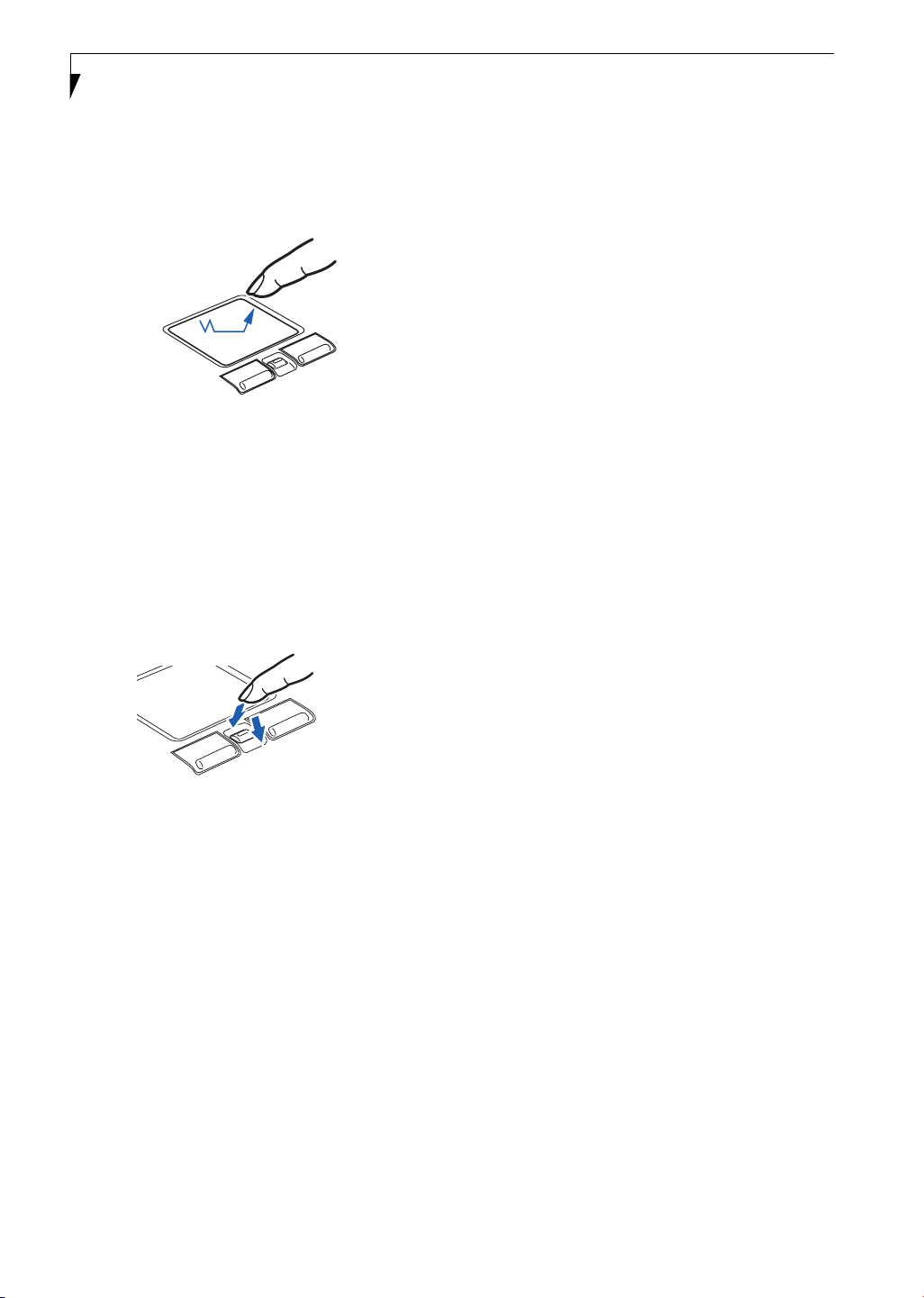
DRAGGING
Dragging means pressing and holding the left button,
while moving the cursor. To drag, move the cursor to
the item you wish to move. Press and hold the left
button while moving the item to its new location and
then release it. Dragging can also be done using the
15
Page 24
LifeBook P5000 Notebook – Section Two
Touchpad. First, tap the Touchpad twice over the item
you wish to move making sure to leave your finger on
the pad after the final tap. Next, move the object to its
new location by moving your finger across the
Touchpad, and then release your finger. (Figure 2-15)
Figure 2-15 Dragging
SCROLLING
Using the Scrolling button allows you to navigate
through a document quickly without using the window’s
scroll bars. This is particularly useful when you are
navigating through on-line pages. To use the Scrolling
button, press the crescent shape at the top or bottom of
the button to scroll up or down a page. When you have
reached the desired section of the page, release the
button. (Figure 2-16)
Figure 2-16 Scrolling
TOUCHPAD CONTROL ADJUSTMENT
If you need to change or adjust any of the touchpad
control functions, you can customize them from the
Mouse properties dialog box in the Control Panel. Click
on Start, select Settings > Control Panel, then doubleclick Mouse.
16
Page 25

Getting to Know Your LifeBook
Volume Control
Your Fujitsu LifeBook notebook has multiple volume
controls which interact with each other.
POINT
Any software that contains audio files will also contain
a volume control of its own. If you install an external
audio device that has an independent volume control,
the hardware volume control and the software volume
control will interact with each other. It should be noted
that if you set your software volume to Off, you will
override the external volume control setting.
CONTROLLING THE VOLUME
The volume can be controlled in several different ways:
■
Volume can be set from within the Volume Control on
the Taskbar.
■
Volume can be controlled with the [F8] and [F9]
functions keys. Pressing [F8] repeatedly while holding
[Fn] will decrease the volume of your notebook. Pressing [F9] repeatedly while holding [Fn] will increase
the volume of your notebook.
POINT
There are seventeen levels through which the function
keys cycle.
■
Volume can be controlled by many volume controls
that are set within individual applications.
■
Certain external audio devices you might connect to
your system may have hardware volume controls.
Each source discussed above puts an upper limit on the
volume level that must then be followed by the other
sources.
We recommend that you experiment with the various
volume controls to discover the optimal sound level.
17
Page 26
LifeBook P5000 Notebook – Section Two
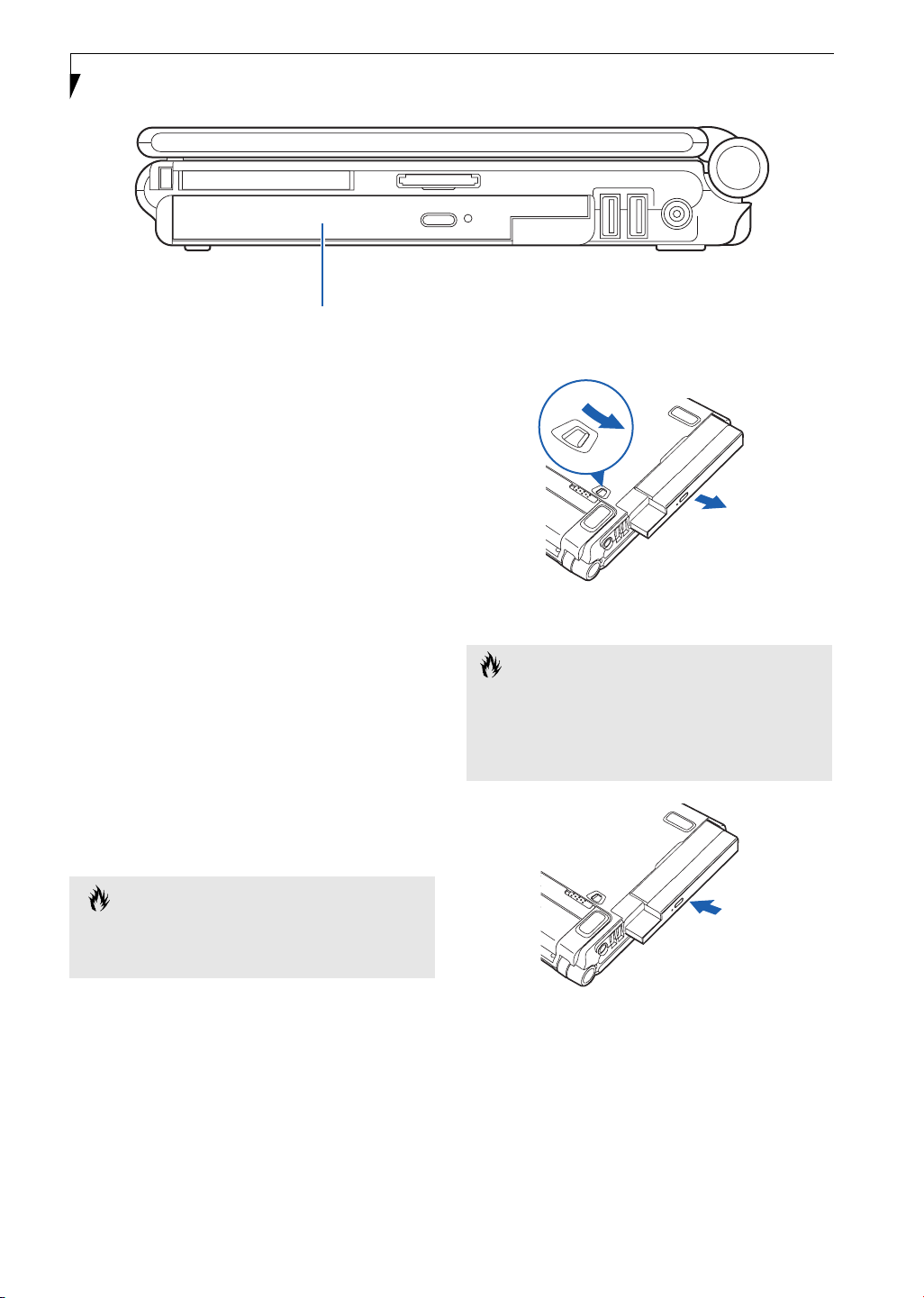
Flexible Bay
Figure 2-17 Flexible Bay
Flexible Bay Devices
Your Fujitsu LifeBook notebook contains a Flexible Bay.
The Flexible Bay can accommodate a modular DVD/
CD-RW combo drive, a modular Lithium ion battery, or
a weight saver. (Figure 2-17)
The modular DVD/CD-RW combo drive allows you to
access movies, software and audio DVD/CDs, as well as
the ability to write to CDs.
The modular Lithium ion battery is a rechargeable
battery that can be used to power your LifeBook notebook when an adapter is not connected.
The Weight Saver is used to fill the bay when no device is
needed.
REMOVING AND INSTALLING
MODULAR DEVICES
To remove and install modular devices in the Flexible
Bay, you can perform either a cold-swapping or hotswapping of the device. Cold-swapping means swapping
devices while your LifeBook notebook is powered off.
Hot-swapping occurs when your system is powered on
with a charged main battery or AC Adapter.
CAUTION
You should never leave your Flexible Bay empty when
the notebook is in operation. If left empty, dust or foreign matter may accumulate inside the notebook.
Cold-swapping
To cold-swap modular devices in your Flexible Bay
follow these easy steps:
1. Close any open files.
2. Shut down your LifeBook notebook.
3. Turn the system over and slide the release latch
(Figure 2-18). Pull out the Flexible Bay device from
the slot.
Figure 2-18 Removing a device from the Flexible Bay
CAUTION
Be careful when aligning and seating devices in the bay.
If the fit is incorrect, you may damage the bay or the
device. If the device does not move easily in the bay,
remove it, and check for dirt or foreign objects. It will
require a firm push to latch the device in place.
Figure 2-19 Installing a device in the Flexible Bay
5. Slide the device you are installing into your notebook until it clicks into place. (Figure 2-19)
6. It is now safe to turn your notebook back on.
7. You can now access and use the device.
Your LifeBook notebook will automatically detect the
new device and activate it within your system. The drive
letters associated with the device will be created and
listed under My Computer and Windows Explorer.
18
Page 27

Hot-swapping
To hot-swap Flexible Bay devices while the system is
powered on, follow these steps:
1. Prior to performing the hot-swap, make sure you
have a charged main battery installed, or an AC
Adapter is powering the system.
2. If your system is in Suspend mode, press the
Suspend/Resume button to resume operation.
3. Click the Unplug or Eject Hardware icon (Windows
2000 Professional) or the Safely Remove Hardware
icon (Windows XP) in the lower right-hand corner
of the screen.
4. From the list that appears, click the device you want
to remove.
5. Pull out the Flexible Bay eject lever. This will push
your device out slightly, allowing you to remove the
device.
6. Slide your device out until it is clear of the bay.
This will require light force.
CAUTION
Be careful when aligning and seating devices in the bay.
If the fit is incorrect, you may damage the bay or the
device. If the device does not move easily in the bay,
remove it, and check for dirt or foreign objects. It will
require a firm push to latch the device in place.
Getting to Know Your LifeBook
7. Slide the device you are installing into your
notebook until it clicks into place.
8. You can now access and use the device.
Your LifeBook notebook will automatically detect the
new device and activate it within your system. The drive
letters associated with the device will be created and
listed under My Computer and Windows Explorer.
19
Page 28

LifeBook P5000 Notebook – Section Two
20
Page 29

3
Getting Started
21
Page 30

LifeBook P5000 Notebook – Section Three
22
Page 31

DC Output Cable
Getting Started
DC Power Jack
AC Adapter
AC Cable
Figure 3-1 Connecting the AC Adapter
Power Sources
Your Fujitsu LifeBook notebook has five possible power
sources: a primary Lithium ion battery, an optional
high-capacity Lithium ion battery, an optional modular
Lithium ion battery, an AC adapter, or an optional Auto/
Airline adapter.
CONNECTING THE POWER ADAPTERS
The AC adapter or optional Auto/Airline adapter
provides power for operating your notebook and
charging the batteries.
Connecting the AC Adapter
1. Plug the DC output cable into the DC power jack
of your LifeBook notebook.
2. Plug the AC adapter into an AC electrical outlet.
(Figure 3-1)
Connecting the Optional Auto/Airline Adapter
1. Plug the DC output cable into the DC power jack
on your notebook.
2. Plug the Auto/Airline adapter into the cigarette
lighter of an automobile with the ignition key in
the On or Accessories position.
OR
3. Plug the Auto/Airline adapter into the DC power
jack on an airplane seat.
Switching from AC Adapter Power or the
Auto/Airline Adapter to Battery Power
1. Be sure that you have at least one charged
battery installed.
2. Remove the AC adapter or the Auto/Airline adapter.
POINT
The Lithium ion battery is not charged upon purchase.
Initially, you will need to connect either the AC adapter
or the Auto/Airline adapter to use your notebook.
23
Page 32

LifeBook P2000 Notebook – Section Three
Figure 3-2 Opening the Display Panel
Display Panel
Your Fujitsu LifeBook notebook contains a display panel
that is backlit for easier viewing in bright environments
and maintains top resolution through the use of activematrix technology.
OPENING THE DISPLAY PANEL
Lift the display backwards, being careful not to touch the
screen, until it is at a comfortable viewing angle.
(Figure 3-2)
ADJUSTING DISPLAY PANEL BRIGHTNESS
Once you have turned on your LifeBook notebook, you
may want to adjust the brightness level of the screen to a
more comfortable viewing level. There are two ways to
adjust the brightness, by using the keyboard or the
power management utility.
Using the Keyboard
Adjusting the brightness using the keyboard changes the
setting only temporarily.
■
[Fn+F6]: Pressing repeatedly will lower the
brightness of your display.
■
[Fn+F7]: Pressing repeatedly will increase the
brightness of the display.
Using the Power Management Utility (Windows
2000 only)
Adjusting the brightness using the Power Management
changes the setting permanently.
1. Double-click the Battery icon in the lower right
corner of your display. This will open the BatteryAid
Properties dialog box.
2. Select the Power Control tab and adjust your
LCD Backlighting to the desired level.
3. Click OK or Apply to permanently change
the settings.
You may need to readjust the brightness level periodically depending on your operating environment.
POINT
The higher the brightness level, the more power the
notebook will consume and the faster your batteries
will discharge. For maximum battery life, make sure that
the brightness is set as low as possible.
CLOSING THE DISPLAY PANEL
Holding the edge of your display panel, pull it forward
until it is flush with the body of your LifeBook notebook.
24
Page 33

Starting Your LifeBook
Notebook
POWER ON
Suspend/Resume/Power On button
The Suspend/Resume/Power On button is used to turn
on your LifeBook notebook from its off state. Once you
have connected your AC adapter or charged the internal
Lithium ion Battery, you can power on your notebook.
POINT
When you turn on your LifeBook notebook be sure you
have a power source. This means that at least one battery is installed and charged, or that the AC or Auto/
Airline adapter is connected and has power.
Figure 2-20 Pressing the power button
Press the Suspend/Resume/Power On button
(Figure 2-20). When you are done working you can
either leave your LifeBook notebook in Suspend mode,
(See Suspend Mode on page 27 for more information), or
you can turn it off. (See Power Off on page 28 for more
information)
CAUTION
Do not carry your LifeBook notebook around with the
power on or subject it to shocks or vibration, as you risk
damaging your notebook.
When you Power On your LifeBook notebook, it will
perform a Power On Self Test (POST) to check the
internal parts and configuration for correct functionality.
If a fault is found, your LifeBook notebook will emit an
audio warning and/or an error message will be displayed.
(See Power On Self Test Messages on page 86 for more
information) Depending on the nature of the problem,
you may be able to continue by starting the operating
system or by entering the BIOS setup utility and revising
the settings.
After satisfactory completion of the Power On Self Test
(POST), your notebook will load your operating system.
Getting Started
POINT
Never turn off your LifeBook notebook during the
Power On Self Test (POST) or it will cause an error message to be displayed when you turn your LifeBook
notebook on the next time.
(See Power On Self Test
Messages on page 86 for more information)
BOOT SEQUENCE
The procedure for starting-up your notebook is termed
the Bootup sequence and involves your notebook’s
BIOS. When your LifeBook notebook is first turned on,
the main system memory is empty, and it needs to find
instructions to start up your notebook. This information
is in the BIOS program. Each time you power up or
restart your notebook, it goes through a boot sequence
which displays a Fujitsu logo until your operating system
is loaded. During booting, your notebook is performing
a standard boot sequence including a Power On Self Test
(POST). When the boot sequence is completed without
a failure and without a request for the BIOS Setup
Utility, the system displays the operating system’s
opening screen.
The boot sequence is executed when:
■
You turn on the power to your LifeBook notebook.
■
You restart your notebook from the Windows
Shut Down dialog box.
■
The software initiates a system restart. Example:
When you install a new application.
■
You reset the system by pressing the three keys
[CTRL+ALT+DEL].
BIOS SETUP UTILITY
The BIOS Setup Utility is a program that sets up the
operating environment for your LifeBook notebook.
Your BIOS is set at the factory for normal operating
conditions, therefore there is no need to set or change
the BIOS’ environment to operate your notebook.
The BIOS Setup Utility configures:
■
Device control feature parameters, such as changing
I/O addresses and boot devices.
■
System Data Security feature parameters, such as
passwords.
Entering the BIOS Setup Utility
To enter the BIOS Setup Utility do the following:
1. Turn on or restart your LifeBook notebook.
2. Press the [F2] key once the Fujitsu logo appears on
the screen. This will open the main menu of the
BIOS Setup Utility with the current settings
displayed.
25
Page 34

LifeBook P5000 Notebook – Section Three
3. Press the [RIGHT ARROW] or [LEFT ARROW] key
to scroll through the other setup menus to review or
alter the current settings.
BIOS Guide
A guide to your notebook’s BIOS is available online.
Please visit our service and support Web site at
www.fujitsupc.com. Once there, select Support, then
select Notebooks under User’s Guides. Select LifeBook
BIOS Guides from the pull-down menu for your LifeBook series. If you are unsure of your notebook’s BIOS
number, refer to your packing slip.
BOOTING THE SYSTEM
We strongly recommend that you not attach any external
devices and do not put a DVD/CD in your drive until
you have gone through the initial power on sequence.
When you turn on your LifeBook notebook for the first
time, it will display a Fujitsu logo on the screen. If you
do nothing the system will load the operating system,
and then the Windows Welcome will begin.
Designed to accommodate the needs of many users, in
many different countries, Windows needs to be configured the first time you use them. Windows has three
parts:
■
Getting Started: You have the opportunity to enter
custom information for your configuration file and
setup your modem so that your LifeBook notebook
will be prepared to dial out.
■
Registration: Easy online registration for Windows
with Microsoft, and for your LifeBook notebook with
Fujitsu.
■
Windows License Agreement and Final Settings:
You have the opportunity to review the Windows
License Agreement.
POINT
You may click Cancel at any time within this process to
shut down Windows. You may restart this process at
any time in the future, but you must complete it in
order to use your computer.
Getting Started
Read the instructions on the screens carefully and fill in
the information as directed. You will be asked for such
items as the language you wish to use, the country in
which you live, your first and last name, and about how
you dial out from where you will be using your LifeBook
notebook. For the modem settings, enter your current
location information where you will be using your LifeBook notebook. If you are not connected to a phone line
and plan to register at a later time, you may click the
Skip button, and you will go directly to the condition of
use page.
Once you have set up your LifeBook notebook to dial
out, Windows will make a free telephone call to test the
settings. If the call is unsuccessful, you will be returned
to the phone settings page where you may try to fix
them. If you are unable to fix the settings please contact
Fujitsu Service and Support. (See Fujitsu Contact Infor-
mation on page 1 for more information). If you would
simply like to move on, and register at a later time, you
may click the Skip button, and you will go directly to the
Condition of Use page.
Windows Registration
If your connection is successful, you will go to a
Registration Confirmation page. Enter the requested
information, then check the box at the bottom to
register your copy of Windows with Microsoft . Once you
have finished, click the Next button to continue.
Final Settings
The first part of your final settings is the Windows End
User License Agreement. Read the agreement carefully.
When you finish reading you must accept or reject the
terms of the agreement and then click on the Next button.
POINTS
■
If you reject the terms of the license agreement you
will be asked to review the license agreement for
information on returning Windows or to shut down
your LifeBook notebook.
■
You cannot use your LifeBook notebook until you
have accepted the License Agreement. If you stop the
process your notebook will return to the beginning of
the Windows Welcome Process, even if you shut your
notebook down and start it up again.
REGISTERING YOUR LIFEBOOK NOTEBOOK
What are the benefits of registering?
You will receive an identification label for your LifeBook
notebook, which, if your notebook is ever lost, may help
in getting it returned to you. You will also receive technical support access and useful product mailings.
How do I register my LifeBook notebook?
You can register your LifeBook by going to our Web site:
www.fujitsupc.com/support
You will need to be set up with an Internet Service
Provider (ISP) to use the last option.
INSTALLING CLICK ME!
The first time you boot up your system, you will see an
icon called Click Me! on the desktop (Windows 2000) or
in the Start folder (Windows XP). When you click the
Click Me! icon, your system will automatically build the
icon tray in the bottom right of the screen. These icons
provide links to utilities that you will frequently access.
26
Page 35

Power Management
Your Fujitsu LifeBook notebook has many options and
features for conserving battery power. Some of these
features are automatic and need no user intervention,
such as those for the internal modem. However, others
depend on the parameters you set to best suit your operating conditions, such as those for the display brightness. Internal power management for your notebook
may be controlled from settings made in your operating
system, pre-bundled power management application, or
from settings made in BIOS setup utility.
Besides the options available for conserving battery
power, there are also some things that you can do to
prevent your battery from running down as quickly.
For example, you can create an appropriate power saving
profile, put your notebook into Suspend mode when it
is not performing an operation, and you can limit the
use of high power devices. As with all mobile, battery
powered computers, there is a trade-off between
performance and power savings.
POWER/SUSPEND/RESUME BUTTON
When your LifeBook notebook is active, the Power/
Suspend/Resume button can be used to manually put
your notebook into Suspend mode. Push the button
when your notebook is active, but not actively accessing
anything, and immediately release the button. You will
hear two short beeps and your system will enter
Suspend mode. (See figure 2-5 on page 6 for location)
If your LifeBook notebook is suspended, pushing the
Power/Suspend/Resume button will return your notebook to active operation. You can tell whether or not
your system is in Suspend mode by looking at the Power
indicator. (See figure 2-5 on page 6) If the indicator is
visible and not flashing, your notebook is fully operational. If the indicator is both visible and flashing, your
notebook is in Suspend mode. If the indicator is not
visible at all, the power is off or your notebook is in
Hibernation mode.
SUSPEND MODE
Suspend or Standby mode in Windows saves the
contents of your LifeBook notebook’s system memory
during periods of inactivity by maintaining power to
critical parts. This mode will turn off the CPU, the
display, the hard drive, and all of the other internal
components except those necessary to maintain system
memory and allow for restarting. Your notebook can be
put in Suspend mode by:
■
Pressing the Power/Suspend/Resume button when
your system is turned on.
■
Selecting Standby from the Windows Shut Down menu.
Getting Started
■
Timing out from lack of activity.
■
Allowing the battery to reach the Dead Battery
Warning condition.
You can change the actions the computer takes when the
lid is closed or buttons are pressed by clicking [Start] ->
Control Panel. Double-click the Power Options icon and
select the Advanced tab.
Your LifeBook notebook’s system memory typically
stores the file(s) on which you are working, open application(s) information, and any other data required to
support the operation(s) in progress. When you resume
operation from Suspend mode, your notebook will
return to the point where it left off. You must use the
Power/Suspend/Resume button to resume operation,
and there must be an adequate power source available, or
your notebook will not resume.
POINTS
■
If you are running your LifeBook notebook on
battery power, be aware that the battery continues
to discharge while your notebook is in Suspend
mode, though not as fast as when fully operational.
■
Disabling the Power/Suspend/Resume button
prevents it from being used to put your LifeBook
notebook in Suspend or Hibernation mode. The
resume function of the button cannot be disabled.
■
If your LifeBook notebook is actively accessing
information when you enter the Suspend or Hibernation mode, changes to open files are not lost. The
files are left open and memory is kept active during
Suspend mode or the memory is transferred to the
internal hard drive during Hibernation mode.
CAUTION
The Suspend or Hibernation mode should not be used
with certain PC Cards. Check your PC Card documentation for more information.
When PC Cards or external devices are in use, Hibernation mode cannot return to the exact state prior to suspension, because all of the peripheral devices will be reinitialized when the system restarts.
HIBERNATION FEATURE
The Hibernation feature saves the contents of your
LifeBook notebook’s system memory to the hard drive as
a part of the Suspend/Resume mode. You can enable or
disable this feature.
Enable or Disable the Hibernation Feature
The default settings is not enabled. To enable or disable
the Hibernation feature follow these easy steps:
1. From the Start menu, select Settings, and then select
Control Panel.
27
Page 36

LifeBook P5000 Notebook – Section Three
2. From the Control Panel select Power Options.
3. Select the Hibernation tab. Select the box to enable
or disable this feature.
Using the Hibernation Feature
1. From the Start menu, select Settings, and then select
Control Panel.
2. From the Control Panel select Power Options.
3. Select the Advanced tab. Select Hibernate from the
pull down menu for Power buttons.
DISPLAY TIMEOUT
The Video Timeout is one of the power management
parameters. This feature saves power by turning off the
display if there is no keyboard or pointer activity for the
user selected timeout period. Any keyboard or pointer
activity will cause the display to restart automatically.
This feature is independent of the Suspend/Resume
button and can be enabled and disabled in Windows and
BIOS setup utility.
HARD DISK TIMEOUT
The Hard Disk Timeout is another one of the power
management parameters. This feature saves power by
turning off the hard drive if there is no hard drive
activity for the user selected timeout period. Any
attempt to access the hard drive will cause it to restart
automatically. This feature is independent of the
Suspend/Resume button and can be enabled and
disabled in Windows and BIOS setup utility.
WINDOWS POWER MANAGEMENT
Power Management
The Power Management icon located in the Windows
Control Panel allows you to configure some of the power
management settings. For example, you can use the
Power Management to set the timeout values for turning
off the display and hard disks whether you are running
the notebook on battery power or one of the adapters.
The settings may also be changed in the BIOS.
POINT
Turning off your LifeBook notebook without exiting
Windows or turning on your notebook within 10 seconds of the notebook being shut off may cause an error
when you start the next time.
POWER OFF
Before turning off the power, check that the Hard Drive,
DVD, CD-ROM, CD-RW, PC Card and the Floppy Disk
Drive Access indicators are all Off. (See figure 2-5 on
page 6) If you turn off the power while accessing a disk
or PC Card there is a risk of data loss. To ensure that
your notebook shuts down without error, use the
Windows shut down procedure.
CAUTION
Be sure to close all files, exit all applications, and shut
down your operating system prior to turning off the
power with the power switch. If files are open when
you turn the power off, you will lose any changes that
have not been saved, and may cause disk errors.
Using the correct procedure to shut down from Windows
allows your notebook to complete its operations and turn
off power in the proper sequence to avoid errors. The
proper sequence is:
1. Click the Start button, and then click Shut Down.
2. Select the Shut Down option from within the
Windows Shut Down dialog box.
3. Click OK to shut down your notebook.
4. Move the power switch to the off position.
If you are going to store your notebook for a month or
more see Care and Maintenance Section.
RESTARTING THE SYSTEM
If your system is on and you need to restart it, be sure
that you use the following procedure.
1. Click the Start button, and then click Shut Down.
2. Select the Restart option from within the Windows
Shut Down dialog box.
3. Click OK to restart your notebook. Your notebook
will shut down and then reboot.
28
Page 37

4
User-Installable
Features
29
Page 38

LifeBook P5000 Notebook – Section Four
30
Page 39

User Installable Features
Lithium ion Battery
Your Fujitsu LifeBook notebook has a Lithium ion
battery that provides power for operating your notebook
when no external power source is available. The battery
is durable and long lasting, but should not be exposed to
extreme temperatures, high voltages, chemicals or other
hazards.
The Lithium ion battery operating time may become
shorter if it is used under the following conditions:
■
When used at temperatures that exceeds a low of 5°C
(41°F) or a high of 35°C (95°F). Extreme temperatures
not only reduce charging efficiency, but can also cause
battery deterioration. The Charging icon on the Status
Indicator panel will flash when you try to charge a
battery that is outside its operating temperature range.
(See Battery Charging Indicator on page 12 for more
information)
■
When using a high current device such as a modem,
DVD/CD-RW drive, or the hard drive, using the AC
adapter will conserve your battery life.
POINTS
■
Actual battery life will vary based on screen brightness, applications, features, power management settings, battery condition and other customer
preferences.DVD, CD-RW, CD-ROM, or hard drive
usage may also have a significant impact on battery
life. The battery charging capacity is reduced as the
battery ages. If your battery is running low quickly,
you should replace it with a new one.
■
Under federal, state, or local law it may be illegal to
dispose of batteries by putting them in the trash.
Please take care of our environment and dispose of
batteries properly. Check with your local government
authority for details regarding recycling or disposing
of old batteries. If you cannot find this information
elsewhere, contact your support representative at 1800-8Fujitsu (1-800-838-5487)
battery make sure the battery that needs to be charged
is installed in your LifeBook notebook and connect the
AC or Auto/Airline adapter.
POINT
Make sure that the Battery Charging indicator and the
percentage charge is shown inside the Battery Level icon
on the Status Indicator Panel.
There is no memory effect on the Lithium ion battery
therefore you do not need to discharge the battery
completely before recharging. The charge times will be
significantly longer if your notebook is in use while the
battery is charging.
The approximate charging times follows:
■
Standard high-capacity battery:
System off : 6.5 hours; system running: 17 hours
If you want to charge the battery more quickly, put your
notebook into Suspend mode, or turn it off while the
adapter is charging the battery. (See Power Management
on page 27 for more information on Suspend mode and
shutdown procedure)
CAUTION
Using heavy current devices such as Modem or frequent
DVD/CD-RW/CD-ROM accesses may prevent charging
completely.
Low Battery State
When the battery is running low, a low battery notification message will appear. If you do not respond to the
low battery message, the batteries will continue to
discharge until they are too low to operate. When this
happens, your notebook will go into Suspend mode.
There is no guarantee that your data will be saved once
the notebook reaches this point.
CAUTION
Do not leave a faulty battery in your LifeBook
notebook. It may damage your AC adapter, optional
Auto/Airline adapter, another battery or your notebook
itself. It may also prevent operation of your notebook
by draining all available current into the bad battery.
RECHARGING THE BATTERIES
If you want to know the condition of the primary
Lithium ion battery, check the Battery Level indicator
located on the Status Indicator panel. The indicator
changes as the battery level changes.
The Lithium ion battery is recharged internally using
the AC adapter or Auto/Airline adapter. To recharge the
CAUTIONS
■
Once the low battery notification message appears,
you need to save all your active data and put your
LifeBook notebook into Suspend mode until you can
provide a new power source. You should provide a
charged battery, an AC power adapter, or Auto/Airline adapter as soon as possible.
■
When you are in Suspend mode there must always
be at least one power source active. If you turn off
the power with the power switch, or remove all
power sources while your LifeBook notebook is in
Suspend mode, any data that has not been saved to
the hard drive will be lost.
Dead Battery Suspend mode shows on the Status indicator just like the normal Suspend mode. Once your
31
Page 40

LifeBook P5000 Notebook – Section Four
notebook goes into Dead Battery Suspend mode you
will be unable to resume operation until you provide
a source of power either from an adapter, or a charged
battery. Once you have provided power, you will need to
press the Suspend/Resume button to resume operation.
In the Dead Battery Suspend mode, your data can be
maintained for some time, but if a power source is not
provided promptly, the Power indicator will stop
flashing and go out, meaning that you have lost the data
that was not stored. Once you provide power, you can
continue to use your notebook while an adapter is
charging the battery.
Shorted Batteries
The Status Indicator panel uses a symbol inside the
battery outline of the Battery Level indicator to display
the operating level available in that battery. (See figure 2-
10 on page 11) If this display shows a Shorted Battery, it
means that the battery is damaged and must be replaced
so it does not damage any other parts of your LifeBook
notebook.
REPLACING THE BATTERY
With the purchase of an additional battery, you can have
a fully charged spare to swap with one that is not
charged.
Swapping Batteries when Additional Power Source
is not Available
To swap batteries in your battery bay when you don’t
have another power source available (such as an AC
Adapter or charged modular battery), follow these easy
steps: (Figure 2-21)
1. Have a charged battery ready to install.
2. Shut down your notebook.
3. Slide and hold the battery release latches to open the
bay. (Figure 2-21)
6. Verify that the battery bay latches click into place.
Figure 2-22 Installing a battery
Swapping Batteries when another Power Source is
available
To swap batteries in your battery bay when you have an
additional power source (such as an AC Adapter or
charged modular battery), follow these easy steps:
(Figure 2-21)
1. Save any open files and close any open applications.
2. Plug in an AC Adapter to ensure power is supplied to
the system, or install a fully charged modular battery
in the Flexible Bay.
3. Slide and hold the battery release latches to open the
bay.
4. Remove the battery from the bay.
5. Slide the new battery into the bay.
6. Verify that the battery bay latches click into place.
POINT
If the Lithium ion battery connector is not fully seated,
you may not be able to use your notebook or charge
your battery.
Figure 2-21 Removing the Battery
4. Remove the battery from the bay.
5. Slide the new battery into the bay. (Figure 2-22)
32
Page 41

Figure 4-1 Loading/Ejecting a 3.5” Floppy Disk
External Floppy Disk Drive
Your LifeBook notebook may have an optional external
floppy disk drive which can read and write information
on removable 1.44MB and 720KB floppy disks.
User Installable Features
Eject Button
CAUTION
If you eject the disk while the Floppy Disk Drive Access
indicator is active, there is a risk of damaging the data
on the disk, the disk itself or even the disk drive.
POINT
Your LifeBook notebook is preconfigured to boot from a
floppy drive. Reference the BIOS manual for further
information on changing the default boot drive.
LOADING A DISK
To load a disk into your disk drive, follow these easy
steps:
1. Orient the disk so that its label is facing upwards
and the shutter side is pointing towards the drive.
(Figure 4-1)
2. Push the disk into the drive until the Eject button
pops out and you hear a click.
POINT
When there is no disk in the drive, the Eject button is
flush with your notebook.
EJECTING A DISK
To eject a disk from the disk drive, follow these easy
steps:
1. Check that the Floppy Disk Drive Access indicator
is inactive.
2. Press the Eject button. This will push your disk
partially out of the drive.
3. Remove the disk.
PREPARING A DISK FOR USE
Before you can use a new disk, it needs to be prepared
so your LifeBook notebook knows where to store information. This preparation is called formatting or initializing a disk. You will need to format new disks, unless
they are preformatted. (Please refer to your operating
system manual for step-by-step instructions on formatting a
disk)
To prevent accidental erasure of the data stored on a
disk, slide the “write protect” tab until a small hole is
exposed. This sets the disk into a protected state where
nothing can be added or removed. If you want to add or
remove data on a protected disk, slide the “write
protect” tab to close the small hole. (Figure 4-2)
Write Enabled
Write Protected
Figure 4-2 Floppy Disk Write Protect
CAUTION
Formatting a floppy disk that already contains data will
erase all of the information on the disk.
33
Page 42

LifeBook P5000 Notebook – Section Four
Figure 4-3 DVD/CD-RW Combo Drive
DVD/CD-RW
Combo Drive
Your Fujitsu LifeBook notebook may contain a DVD/
CD-RW combo drive. A DVD player gives you access to
movie, software, and audio DVD/CDs. A CD-RW player
allows you to access software or audio CDs, and to write
data onto recordable CDs.
DVD/CD-RW COMBO DRIVE SOFTWARE
With the DVD/CD-RW drive and DVD/CD-RW drive
software you can play DVD movies on your notebook.
The DVD/CD-RW includes controls which allow you to
take full advantage of the features of a DVD movie, as
well as standard features such as fast forward, fast
reverse, pause, etc. With the CD-RW drive, you can read
audio CDs, and write data onto a recordable CD-R or
CD-RW disc.
POINT
■
Prior to using your DVD/CD-RW Combo Drive, you
must install the DVD/CD-RW drive software. Refer
to the applicable readme file on the Applications CDROM for instructions on installing you DVD/CD-RW
Combo Drive software.
■
You should periodically check the Fujitsu Web site at
www.fujitsupc.com for current updated drivers.
Media Eject Button
Media Holder Tray
POINT
Prolonged use of the DVD/CD-RW drive, such as
watching a DVD movie, will substantially reduce your
battery life.
LOADING A DVD, CD, CD-R, OR CD-RW
(“MEDIA”)
To load a disc into your DVD/CD-RW drive, follow
these steps (Figure 4-4):
1. Push and release the eject button on the front of the
DVD/CD-RW drive to open the holder tray. The
tray will come out of the notebook a short distance.
2. Gently pull the tray out until a media disc can easily
be placed in the tray.
CAUTION
There may be a protective sheet in the tray from when it
was shipped; make sure it is removed before operating
the drive, otherwise you may damage the drive.
3. Place the media into the tray, label side up, with the
hole in the center of the disc. Snap the disc onto the
raised circle in the center of the tray.
4. Gently push the holder tray back in until you hear a
click.
CAUTION
Do not operate your DVD/CD-RW drive unless your
LifeBook notebook is sitting on a flat surface. Using a
drive when the system is not level may damage the
drive or prevent proper operation.
34
Page 43

POINT
If you have disabled the Auto Insert Notification
Function, you will have to start the drive from
your desktop, since your notebook will not automatically recognize that media has been loaded.
User Installable Features
click InterVideo WINDVD or double-click on the
InterVideo WINDVD icon on the desktop. This will
launch the DVD movie.
2b. Windows XP only: The first time you insert a movie
into the DVD/CD-RW tray, you will be prompted to
select what you want the system to do when discs are
inserted (e.g., start automatically or wait for a
prompt). Until you make a selection, you will receive
the same prompt whenever you insert a disc.
3. Click OK to close the About DVD Player
Performance dialog box and the movie will begin.
Opening the DVD/CD-RW Drive Control Panel
With most DVD-ROMs, you have the option of altering
how the movie should play and what you wish to view.
You can do this by using the DVD/CD-RW Combo
Drive control panel and the mouse.
1. Right-click on the movie screen to open a
dropdown menu for options.
2. Select View, then Player for all the controls available.
This will open the control panel into the bottom of
the screen.
Figure 4-4 Loading/Removing Media
REMOVING MEDIA
1. Push and release the eject button on the front of
the DVD/CD-RW drive. This will stop the drive
and the holder tray will come out of the notebook a
short distance.
2. Gently pull the tray out until the disc can easily be
removed from the tray.
3. Carefully remove the media disc from the holder
tray.
4. Gently push the holder tray back in until you
hear a click.
USING THE DVD/CD-RW DRIVE SOFTWARE
POINT
■
Prior to using your DVD/CD-RW Combo Drive, you
must install the DVD/CD-RW drive software. Refer
to the applicable readme file on the Applications CDROM for instructions on installing you DVD/CD-RW
Combo Drive software.
■
For details on using your DVD/CD-RW drive, refer to
the Help file that comes with the application.
Starting a DVD Movie
1. Insert the DVD movie into the DVD/CD-RW drive of
your notebook. If the CD AutoRun feature activates,
skip Step 2.
2a. Windows 2000 only: From the Start menu, select
Programs, then select InterVideo WINDVD and
Using the DVD/CD-RW Drive Control Panel
The DVD/CD-RW Combo Drive software allows you to
watch the movie much like a VCR player. You have the
option to pause, rewind, fast-forward and stop the
movie at any point.
1. To Pause the movie, click the button.
2. To Rewind the movie, click the button to rewind
to a specific portion of the movie, or the button
to return to the opening screen.
3. To Fast-forward the movie, click the button to
forward to a specific portion of the movie, or the
button to jump to the ending credits.
4. To Stop the movie, click the button.
Exiting the DVD/CD-RW Application
1. Click on the U located in the upper right corner of
the title bar. This will open a DVD/CD-RW drive
dialog box.
2. Click Yes to stop and exit the movie, or No to close
the DVD/CD-RW drive dialog box and return to the
movie.
USING DOLBY
TM
HEADPHONE
The Dolby Headphone utility lets you enjoy multichannel sound sources, such as movies, with realistic
surround sound using your conventional stereo headphones.
Dolby Headphone is a signal processing system that
enables your stereo headphones to realistically portray
the sound of a five-speaker playback system.
35
Page 44

LifeBook P5000 Notebook – Section Four
POINT
■
Media discs which do not have the Dolby Surround
5:1 symbol will not support Dolby Headphone.
■
After making changes to the Dolby Headphone
feature and clicking OK, wait at least ten seconds
before making another change in order to allow the
system to stabilize.
To use the Dolby Headphone feature, perform the
following steps:
1. Double click the InterVideo WinDVD icon on your
desktop.
2. On the toolbar that appears, click the Properties
button (the fourth button from the left, with the
image of a wrench).
3. On the Properties window, select the Dolby Headphone tab.
4. To enable Dolby Headphone, check the Enable
Dolby Headphone box. To change the type of
surround sound, select one of the radio buttons
listed under Room Filter Setting.
5. Click OK. The Dolby Headphone feature will now
be enabled until you disable it by unchecking Enable
Dolby Headphone.
USING THE DVD/CD-RW DRIVE
ON BATTERY POWER
Since a DVD/CD-RW drive consumes a lot of power,
your overall battery life will be shorter when operating
the drive continuously (such as watching a DVD movie)
than during standard operation. Many movies run-times
are longer than your LifeBook notebook can support on a
single battery. If you are watching a DVD movie on
battery power you may need to swap in an additional,
charged battery or attach AC power during the movie to
view it in its entirety.
POINT
■
Prolonged use of the DVD/CD-RW drive, such as
when watching a DVD movie, will substantially
reduce your notebook’s battery life. Many movie
run-times are longer than your system can support
on a single battery. If you are watching a DVD
movie on battery power you may need to swap in
an additional, charged battery or attach AC power
during the movie to view it in its entirety.
■
An additional fully-charged battery is highly recommended if you will be watching DVD movies on
battery power. If you don’t have an additional
battery, you may purchase one either on-line at
www.fujitsupc.com or call 1-877-372-3473.
To Watch a Movie on Battery Power:
1. Have an additional full-charged battery or your
AC adapter ready for use.
2. Start watching your DVD movie.
3. When the low battery warning occurs, immediately
stop the movie and exit the DVD/CD-RW drive.
CAUTION
If you do not stop the DVD/CD-RW drive quickly and
the LifeBook notebook attempts to auto-suspend
(critical battery low state) the notebook will shut down
improperly. If this occurs, you will need to install a fresh
power source (either a charged battery or AC Adapter).
4. Connect an AC Adapter to your system, or install a
fully charged battery in the Flexible Bay (after
removing any modular devices that may be present
in the bay) prior to removing the main battery.
5. Manually place your notebook into suspend mode
by depressing the Suspend button and replace the
discharged battery with an additional fully-charged
battery.
6. Resume your notebook by pressing the Suspend
button again. This step is not required if you
attached AC power without entering suspend mode.
7. Restart your DVD/CD-RW drive, locate and skip to
the chapter of the movie you were last watching.
8. Continue watching your DVD movie.
POINT
Some shorter DVD movies may not require you to swap
batteries or attach AC power to complete them.
However, it is best to be prepared since actual battery life
while operating the DVD/CD-RW drive cannot be
guaranteed.
AUTO INSERT NOTIFICATION FUNCTION
The Auto Insert Notification function allows your LifeBook notebook to automatically start a DVD/CD as soon
as it is inserted in the DVD/CD-RW drive and the tray is
closed. Your notebook will begin playing an audio DVD/
CD or will start an application if the DVD/CD includes an
auto run file.
To prevent a CD from playing automatically as soon as it
is inserted, refer to the related help file for your specific
operating system.
36
Page 45

Eject Button
Figure 4-5 Installing/Removing PC Cards
User Installable Features
PC Card Slot
PC Card
PC Cards
Your Fujitsu LifeBook notebook supports Type I and II
PC Cards, which can perform a variety of functions.
Some available PC Cards:
■
Fax/data modem cards
■
Local area network (LAN) cards
■
IDE solid-state disk cards
■
SCSI cards
■
Wireless LAN (802.11b) cards
■
Other PC Cards that conform to PCMCIA 2.1 or
CardBus standards
For further information, refer to the instructions
supplied with your PC Card.
INSTALLING PC CARDS
PC Cards are installed in the PC Card slot. To install a
PC Card, follow these easy steps: (Figure 4-5)
WARNINGS
■
Installing or removing a PC Card during your Life-
Book notebook’s shutdown or bootup process may
damage the card and/or your notebook.
■
Do not insert a PC Card into a slot if there is water or
any other substance on the card as you may permanently damage the card, your LifeBook notebook, or
both.
1. See your PC Card manual for specific instructions
on the installation of your card. Some PC Cards
may require your notebook to be Off while
installing them.
2. Make sure there is no PC Card currently in the slot.
If there is, see Removing PC Cards.
3. Insert your PC Card into the slot, with the product
label facing up.
4. Push the card into the slot firmly until it is seated
in the opening. You will hear a click and the Eject
button will pop away from your notebook.
REMOVING PC CARDS
To remove a PC Card, follow these easy steps:
CAUTION
Windows has a shutdown procedure for PC Cards that
must be followed before removing a card. (Please
review your operating system manual for the correct
procedure).
1. See your PC Card manual for specific instructions
on removing your card. Some PC Cards may require
your notebook to be in Suspend Mode or Off while
removing them.
POINT
If the dialog box states that the device cannot be
removed, you must save all of your open files, close
any open applications and shut down your notebook.
Once your notebook has been shut down, you must
turn Off the power using the power switch.
2. Push the Eject button in until it is flush with the
notebook. This will push the PC Card slightly out of
the slot allowing you to remove the card.
CAUTION
If the PC Card has an external connector and cable, do
not pull the cable when removing the card.
37
Page 46

LifeBook P5000 Notebook – Section Four
CF Card
Figure 4-6 Installing/Removing CF Cards
CF Cards
Your Fujitsu LifeBook notebook supports Compact
Flash (CF) cards, which can perform a variety of functions.
Some available CF Cards:
■
Fax/data modem cards
■
Local area network (LAN) cards
■
Wireless LAN (802.11b) cards
■
IDE solid-state disk cards
For further information, refer to the instructions
supplied with your PC Card.
INSTALLING CF CARDS
CF Cards are installed in the CF Card slot. To install a
CF Card, follow these steps: (Figure 4-6)
CF Card Slot
Eject Button
CF Slot Plug
Figure 4-7 Removing CF Slot plug
3. When the CF Slot plug is ejected, remove it from the
slot.
4. Insert your CF Card into the slot, with the product
label facing up.
WARNINGS
■
Installing or removing a CF Card during your Life-
Book notebook’s shutdown or bootup process may
damage the card and/or your notebook.
■
Do not insert a CF Card into a slot if there is water or
any other substance on the card as you may permanently damage the card, your LifeBook notebook, or
both.
1. See your CF Card manual for specific instructions
on the installation of your card. Some CF Cards
may require your notebook to be Off while
installing them.
2. When you receive your LifeBook, there will be a
protective plug installed in the slot. Whenever you
don’t have a CF Card installed, be sure to replace the
plug to prevent system contamination. To remove
the plug, press the CF Card eject button. (Figure 4-7)
38
CF Card
Figure 4-8 Installing a CF Card
5. Push the card into the slot firmly until it is seated
in the opening. You will hear a click and the Eject
button will pop away from your notebook.
Page 47

REMOVING CF CARDS
To remove a CF Card, follow these easy steps:
CAUTION
Windows has a shutdown procedure for CF Cards that
must be followed before removing a card. (Please
review your operating system manual for the correct
procedure).
1. See your CF Card manual for specific instructions
on removing your card. Some CF Cards may require
your notebook to be in Suspend Mode or Off while
removing them.
POINT
If the dialog box states that the device cannot be
removed, you must save all of your open files, close
any open applications and shut down your notebook.
Once your notebook has been shut down, you must
turn Off the power using the power switch.
2. Push the Eject button in until it is flush with the
notebook. This will push the CF Card slightly out of
the slot allowing you to remove the card.
User Installable Features
Figure 4-9 Installing a CF Card
39
Page 48

LifeBook S5000 Notebook – Section Four
Note: A Memory Stick is used
for illustration purposes.
Memry Stick/SD Card Eject Button
Figure 4-3 Installing a Memory Stick/SD Card
Memory Stick/ Secure Digital Slot
Your LifeBook notebook supports the following
memory cards, on which you can store and transfer data
to and from a variety of digital devices. These cards use
flash memory architecture, which means they don’t need
a power source to retain data.
■
SD Memory Card
■
Memory Stick Media
■
Memory Stick Select Media
■
Memory Stick Duo Media
■
Memory Stick PRO Media
Memory Stick
Figure 4-4 Memory Stick and Secure Digital Card
INSTALLING MEMORY STICK/SD CARDS
Memory Sticks and SD Cards are installed in the
Memory Stick/SD Card slot (Figure 4-3). To install a
Memory Stick or SD Card, follow these steps:
POINTS
• Some of the media in the above list may have
more features than others.
• Memory Stick PRO’s high-speed data rate when
using a parallel interface is not supported.
• An adapter is required for Memory Stick Duo.
• Copyright Protection Technology cannot be used.
• MultiMedia Cards (MMC) and Secure MMC are
not supported.
Memory Stick is a flash memory technology developed
by Sony Electronics. Memory Stick allows you to record,
transfer and share digital content, such as digital
pictures, movies, music, voice, and computer data and
applications.
Secure Digital (SD) Cards are very similar to Memory
Sticks, but they are shorter. Like the Memory Stick, SD
Cards allow portable storage among a variety of devices,
such as cell phones, GPS systems, digital cameras, and
PDAs. SD Cards transfer data quickly, with low battery
consumption. Like the memory stick, it uses flash
memory architecture.
40
WARNING
■
Installing or removing a Memory Stick or SD Card
during your LifeBook notebook’s shutdown or bootup
process may damage the card and/or your LifeBook
notebook.
■
Do not insert a card into a slot if there is water or any
other substance on the card as you may permanently
damage the card, your LifeBook notebook, or both.
1. See your Memory Stick or SD Card manual for
instructions on the installation of your card. Some
cards may require that your notebook is off while
installing them.
2. Make sure there is no card currently in the slot. If
there is, see Removing a Memory Stick/SD Card.
3. Insert your PC Card into the slot with the product
label facing up.
4. Push the card firmly into the slot until it is seated in
the connector.
Page 49

REMOVING A MEMORY STICK/SD CARD
To remove a Memory Stick or SD Card, follow these easy
steps:
POINT
See your Memory Stick or SD Card manual for specific
instructions on the removal of your card. Some cards
may require your LifeBook notebook to be in Suspend
Mode or Off while removing them.
Push the Memory Stick or SD Card in until it unlatches.
It will then eject from the slot for removal.
Memory Stick/SD Card
41
Page 50

LifeBook P5000 Notebook – Section Four
Memory Upgrade Module
Your LifeBook notebook comes with 256MB or 512MB
of in-slot high speed Double Data Rate (DDR) Synchronous Dynamic RAM (SDRAM) factory installed. To
increase your LifeBook notebook’s memory capacity,
you may install a larger memory upgrade module.
If you have 256MB pre-installed, and you would like to
increase it to 512MB, you will need to remove the 256MB
module and replace it with a 512MB module. The
memory upgrade must be a dual-in-line (DIMM)
SDRAM module. To ensure 100% compatibility,
purchase the memory module only from the Fujitsu web
store at www.fujitsupc.com.
CAUTION
The memory upgrade module can be severely damaged
by electrostatic discharge (ESD). Be sure you are properly
grounded when handling and installing the module.
ACCESSING THE MEMORY COMPARTMENT
To gain access to the memory compartment, follow these
steps:
5. Pry the narrow spacer panel in back of the keyboard
away from the system. There is a small gap directly
behind the F9 key with which you can lift the panel
(press the F9 key to access the gap). (Figure 4-6)
Spacer
panel
Figure 4-6 Lifting the spacer panel
6. Slide the keyboard backward slightly until it disengages and can be lifted freely. (Figure 4-7)
WARNING
You must turn off power and remove any modem
connection before installing the memory upgrade
module.
1. Turn off power to your LifeBook notebook, and
remove any power adapter (AC or auto/airline),
battery pack, and modem connection.
2. Place your LifeBook notebook with the bottom
facing up on a clean work surface.
3. Using a Phillips screwdriver, remove the three screws
from the holes in the battery compartment.
(Figure 4-5)
Figure 4-5 Removing screws from battery compartment
4. Turn the system over and open the top cover all the
way, so that it is lying flat on the work surface.
Figure 4-7 Sliding the keyboard
CAUTION
Be very careful when pivoting the keyboard below. The
keyboard is connected with fragile flat cables.
7. Carefully pull the disengaged keyboard towards the
front of the system until it is lying on the display,
exposing the memory compartment.
Figure 4-8 Folding the keyboard back
POINT
The memory slot is already filled when you receive your
system. In order to upgrade the memory, you must first
remove the old memory chip.
42
Page 51

User Installable Features
REMOVING A MEMORY MODULE
1. Perform steps 1 through 7 of Accessing the Memory
Compartment.
2. Pull the clips sideways away from each side of the
memory upgrade module at the same time.
(Figure 4-9)
Figure 4-9 Removing a memory module
3. While holding the clips out, remove the module
from the slot by lifting it up and pulling towards the
back of your LifeBook notebook.
4. Store the memory upgrade module in a static
guarded sleeve.
5. Install a new memory module as detailed in the
procedure below.
6. Replace the keyboard by following steps 10 and 11 of
Installing a Memory Upgrade Module.
INSTALLING A MEMORY MODULE
1. Align the connector edge of the memory upgrade
module, chip side up, with the connector slot in the
compartment. (Figure 4-10)
until it is seated. Fit the tabs on the keyboard into
the locating holes in the computer. (Figure 4-11)
Tabs
Figure 4-11 Reinstalling the keyboard
12. Replace the spacer panel you removed in step 4.
(Figure 4-12) and reinstall the three screws. Installation of the new memory module is now complete.
Figure 4-12 Replacing the spacer panel
POINT
The memory upgrade module is not something you
routinely remove from your LifeBook notebook. Once it
is installed, you should leave it in place unless you want
to increase system memory capacity.
Figure 4-10 Installing a memory module
2 . Insert the memory upgrade module at a 45o angle
and press it firmly onto the connector.
3. Press the memory upgrade module down into the
compartment until it locks underneath the retaining
clip. You will hear a click when it is properly in place.
(Figure 4-10)
Replacing the Keyboard
1. Carefully lay the keyboard back into its original
position, and slide it towards the back of the unit
CHECKING THE COMPUTER RECOGNITION
OF NEW MEMORY CAPACITY
Once you have changed the system memory capacity
by either adding or removing a memory upgrade
module, be sure to check that your LifeBook notebook
has recognized the change.
You can check the memory capacity by looking at the
main menu of the BIOS setup:
1. Turn on the power to your LifeBook notebook using
the power switch.
2. Allow the system to start booting and press the F2
key once the Fujitsu logo appears on the screen. This
will open the main menu of the BIOS setup with the
current settings displayed. (See BIOS Setup Utility on
page 25 for more information) Use the right arrow
key to select Info in the BIOS Setup menu.
The System Memory and the Extended Memory
capacity, as detected by your LifeBook notebook during
43
Page 52

LifeBook P5000 Notebook – Section Four
the Power On Self Test (POST), are displayed at the
bottom of the Info menu screen. The chart below shows
you the possible displays that can be shown on the main
menu screen.
POINT
If the total memory displayed is incorrect, check that
your memory upgrade module is properly installed. (If
the module is properly installed and the capacity is still
not correctly recognized, see the Troubleshooting section starting on page 77)
Installed Displayed
Slot 1
256MB
512MB
Total RAM
Installed
256MB
512MB
System
Memory
640K
640K
Extended
Memory
255MB
511MB
44
Page 53

User Installable Features
Device Ports
Your Fujitsu LifeBook notebook comes equipped with
multiple ports to which you can connect external devices
including: disk drives, keyboards, modems, printers, etc.
MODEM (RJ-11) TELEPHONE JACK
The modem (RJ-11) telephone jack is used for an
internal modem. To connect the telephone cable follow
these easy steps: (See figure 2-7 on page 9 for location)
1. Align the connector with the port opening.
2. Push the connector into the port until it is seated.
3. Plug the other end of the telephone cable into a
telephone outlet.
The modem sound is deactivated by default, to activate
modem sound follow these easy steps:
1. Right click on the Speaker icon in your system tray.
2. Select Open Volume.
3. Select Option/Properties.
4. Under “Show the following volume controls”, click
on Phone and click OK.
5. Uncheck the Mute box under Phone Balance.
WARNING
The internal modem is not intended for use with Digital
PBX systems. Do not connect the internal modem to a
Digital PBX as it may cause serious damage to the internal modem or your entire LifeBook notebook. Consult
your PBX manufacturer’s documentation for details.
Some hotels have Digital PBX systems. Be sure to find
out BEFORE you connect your modem.
POINTS
■
The internal modem is designed to the ITU-T V.90
standard. Its maximum speed of 53000bps is the
highest allowed by FCC, and its actual connection
rate depends on the line conditions. The maximum
speed is 33600bps at upload.
■
The internal modem on all Fujitsu LifeBook notebooks
are registered for use in the United States and Canada. The modem may be certified in other countries.
1. Align the connector with the port opening.
2. Push the connector into the port until it is seated.
3. Plug the other end of the cable into a LAN outlet.
IEEE 1394 PORT
The IEEE 1394 port (also known as “Firewire” or
“iLink”) allows you to connect devices that are
compliant with IEEE standard 1394. This port is effectively a very fast communications port. Some digital
devices - such as digital cameras - use IEEE 1394 ports
for fast transfer of digital files and data.
In order to connect an IEEE 1394 device, follow these
steps: (See figure 2-7 on page 9 for location)
1. Align the connector with the port opening.
2. Push the connector into the port until it is seated.
S-VIDEO OUT PORT (TV OUT)
The S-Video port allows you to connect and use directly
any S-Video device, such as a VCR or television. The
S-Video standard provides for a higher quality picture
than NTSC or PAL. In order to connect an S-Video
device, follow these easy steps: (See figure 2-5 on page 6
for port location)
1. Attach the Mini S-Video Adapter you received with
the system to the S-Video cable of the device to
which you want to connect.
S-Video
Cable
Mini S-Video
Adapter
Figure 2-23 Attaching the adapter
2.Align the connector with the port opening. (Figure 2-
24)
INTERNAL LAN (RJ-45) JACK
The internal LAN (RJ-45) jack is used for an internal
Fast Ethernet (10/100 Base-T/Tx) connection. If your
notebook has been configured with internal LAN
capability you will need to configure your notebook
to work with your particular network. (Please refer to
your network administrator for information on your
network configuration.) To connect the LAN cable follow
these easy steps: (See figure 2-6 on page 8 for location)
Figure 2-24 Connecting the cable
2. Push the connector into the port until it is seated.
45
Page 54

LifeBook P5000 Notebook – Section Four
When S-Video is connected, you can toggle the S-Video
device on and off by pressing the [F11] key while
holding down the [Fn] key.
UNIVERSAL SERIAL BUS PORTS
The Universal Serial Bus 2.0 ports allow you to connect
USB devices such as external game pads, pointing
devices, keyboards and/or speakers. USB 2.0 is much
faster than USB 1.1 (Its 480Mbps transfer rate is 40
times faster than that of USB 1.1). USB 2.0 ports are
backward-compatible to work with USB 1.1 devices.
In order to connect a USB device follow these easy steps:
(See figure 2-7 on page 9 for port location)
1. Align the connector with the port opening.
2. Push the connector into the port until it is seated.
HEADPHONE JACK
The headphone jack allows you to connect headphones
or powered external speakers to your notebook. Your
headphones or speakers must be equipped with a 1/8”
(3.5 mm) stereo mini-plug. In order to connect headphones or speakers follow these easy steps: (See figure 2-7
on page 9 for location)
1. Align the connector with the port opening.
2. Push the connector into the port until it is seated.
POINT
If you plug headphones into the headphone jack, the
built-in stereo speakers will be disabled.
MICROPHONE JACK
The microphone jack allows you to connect an external
mono microphone. Your microphone must be equipped
with a 1/8”(3.5 mm) mono mini-plug in order to fit into
the microphone jack of your notebook. In order to
connect a microphone follow these easy steps: (See
figure 2-5 on page 6 for location)
1. Align the connector with the port opening.
2. Push the connector into the port until it is seated.
MINI-VGA PORT
The mini-VGA port allows you to connect an external
monitor. In order to connect an external monitor follow
these easy steps:
1. Take the mini-VGA cable out of the accessory
package that came with your system.
1. Align the connector with the port opening.
2. Push the connector into the port until it is seated.
(Figure 2-25)
Figure 2-25 Installing the Mini-VGA Cable
POINT
Pressing the [Fn] + [F10] keys allows you to change
your selection of where to send your display video. Each
time you press the key combination, you will
step to the next choice, starting with the built-in display
panel only, moving to the external monitor only, finally
moving to both the built-in display panel and an
external monitor.
OPTICAL DIGITAL AUDIO CONNECTOR
The optical digital audio-out connector allows you to
download digital audio to MiniDisc recorders. It uses
SPDIF (Sony Philips Digital Interface) format. Use the
following setting when using the digital audio-out
connector. (See figure 2-7 on page 9 for location)
POINTS
■
When headphones or a SPDIF cable is installed, the
speakers are disabled.
■
Before using the SPDIF function, make sure that
WinDVD software is installed on your system.
■
Certain older CDs and DVDs will not work in conjunction with the SPDIF connector.
1. Connect the MiniDisc recorder or external speaker
to the Optical Digital Audio-Out Connector.
2. Insert the disk you want to play in the DVD/CD-RW
tray.
3. Click on Start --> Programs --> InterVideo
WinDVD. (In Windows XP systems, you can go
directly from Start to InterVideo WinDVD.)
4. When the WinDVD interface appears, click on the
Properties icon in the bottom of the display (it looks
like a wrench).
5. Click on the Audi o tab and select Enable S/PDIF
output.
6. Click [Apply].
46
Page 55

POINTS
■
The frequency of the digital sound output from the
SPDIF output connector is fixed to 48KHz. If a
sampling rate convertor is not installed in your
connecting digital electronic device (e.g., MD player),
recording is not possible. Please see the user manuals
for the electronic devices for further details.
■
The sound recorded through connecting a digital
electronic device (e.g., MD player) to the SPDIF
output connector cannot be used as digital output.
All output data from the SPDIF output connector has
copyright protection information included.
■
Please be careful, as there are several types of cables
for connecting a digital electronic device (e.g., MD
player) to the digital audio-out connector, depending
on the connector type. The connector on your computer is an Optical Mini Plug (3.5mm diameter mini
plug)
User Installable Features
47
Page 56

LifeBook P5000 Notebook – Section Four
48
Page 57

5
Using the Integrated
Wireless LAN*
*Optional device
49
Page 58

LifeBook P5000 Notebook – Section FIve
50
Page 59

WIreless LAN User’s Guide
FCC REGULATORY INFORMATION
Please note the following regulatory information related
to the optional wireless LAN device.
Regulatory Notes and Statements
Wireless LAN, Health and Authorization for use
Radio frequency electromagnetic energy is emitted from
Wireless LAN devices. The energy levels of these emissions, however, are far much less than the electromagnetic energy emissions from wireless devices such as
mobile phones. Wireless LAN devices are safe for use by
consumers because they operate within the guidelines
found in radio frequency safety standards and recommendations. The use of Wireless LAN devices may be
restricted in some situations or environments, such as:
• On board an airplane, or
• In areas in which volatile gases are present, or
• In situations where the interference risk to other
devices or services is perceived or identified as
harmful.
In cases in which the policy regarding use of Wireless
LAN devices in specific environments is not clear (e.g.,
airports, hospitals, chemical/oil/gas industrial plants,
private buildings), obtain authorization to use these
devices prior to operating the equipment.
Regulatory Information/Disclaimers
Installation and use of this Wireless LAN device must be
in strict accordance with the instructions included in the
user documentation provided with the product. Any
changes or modifications made to this device that are
not expressly approved by the manufacturer may void
the user’s authority to operate the equipment. The
Manufacturer is not responsible for any radio or television interference caused by unauthorized modification
of this device, or the substitution or attachment of
connecting cables and equipment other than those specified by the manufacturer. It is the responsibility of the
user to correct any interference caused by such unauthorized modification, substitution or attachment. The
Manufacturer and its authorized resellers or distributors
will assume no liability for any damage or violation of
government regulations arising from failure to comply
with these guidelines.
Federal Communications Commission statement
This device complies with Part 15 of FCC Rules.
Operation is subject to the following two conditions:
(1) This device may not cause interference, and, (2) This
device must accept any interference, including interference that may cause undesired operation of this device.
FCC Interference Statement
This equipment has been tested and found to comply
with the limits for a Class B digital device, pursuant to
Part 15 of the FCC Rules. These limits are designed to
provide reasonable protection against harmful interference in a residential installation. This equipment generates, uses, and can radiate radio frequency energy. If not
installed and used in accordance with the instructions, it
may cause harmful interference to radio communications. However, there is no guarantee that interference
will not occur in a particular installation.
If this equipment does cause harmful interference to
radio or television reception, which can be determined
by turning the equipment off and on, the user is encouraged to try and correct the interference by one or more
of the following measures:
1. Reorient or relocate the receiving antenna.
2. Increase the distance between the equipment and
the receiver.
3. Connect the equipment to an outlet on a circuit
different from the one the receiver is connected to.
4. Consult the dealer or an experienced radio/TV
technician for help.
FCC Radio Frequency Exposure statement
This Wireless LAN radio device has been evaluated
under FCC Bulletin OET 65C and found compliant with
the requirements as set forth in CFR 47 Sections 2.1091,
2.1093, and 15.247 (b) (4) addressing RF Exposure from
radio frequency devices. The radiated output power of
this Wireless LAN device is far below the FCC radio
frequency exposure limits. Nevertheless, this device shall
be used in such a manner that the potential for human
contact during normal operation is minimized. When
using this device, a certain separation distance between
antenna and nearby persons must be maintained to
ensure RF exposure compliance. In order to comply with
RF exposure limits established in the ANSI C95.1 standards, the distance between the antennas and the user
should not be less than 20 cm (8 inches).
Export restrictions
This product or software contains encryption code
which may not be exported or transferred from the US
or Canada without an approved US Department of
Commerce export license. This device complies with
Part 15 of FCC Rules., as well as ICES 003 B / NMB 003
B. Operation is subject to the following two conditions:
(1) this device may not cause harmful interference, and
(2) this device must accept any interference received,
including interference that may cause undesirable operation. Modifications not expressly authorized by Fujitsu
PC Corporation may invalidate the user's right to
operate this equipment.
51
Page 60

LifeBook P5000 Notebook Section Five
Before Using the Wireless LAN
The Integrated Wireless LAN is an optional device available for Fujitsu mobile computers. This manual
describes the basic operating procedures for the Wireless
LAN (referred to as the “device” in this manual) and
how to set up a wireless LAN network. Before using this
device, read this manual carefully to ensure correct operation of the device. Keep this manual in a safe place for
reference while using the device.
Types of Wireless LANs Covered by this Document
This document is applicable to systems containing one
of the following two devices. Most of the procedures are
identical. Sections that differ between the two devices
have been noted in the text:
■
Intel PROSet Wireless LAN
■
Broadcom Wireless LAN
To determine which device is present in your system,
click [Start] -> [Settings (Windows 2000 only)] ->
Control Panel. If there is an icon named “Intel PROSet”,
you have the Intel device; if there is an icon named
“Broadcom Wireless Utility”, you have the Broadcom
device.
■
This device complies with Wi-Fi, and is able to communicate at the maximum transfer rate of 11 Mbps.
■
The maximum communication range is approximately 80 feet (25 meters) inside a building. The
range may be shorter depending upon the installation
factors, such as walls and columns.
■
Unauthorized access can be prevented with the use of
an SSID and an encryption key (also known as a WEP
key).
Wireless LAN Modes Using this Device
Ad Hoc Mode (See Figure 1)
The “Ad Hoc Mode” refers to the network connecting
two computers using wireless LAN cards. This connection is called an “Ad Hoc network.”
Using an Ad Hoc network, you can obtain a network
connection easily and at a low cost.
In the Ad Hoc mode, you can use the function
supported by Microsoft Network, such as File and Print
Sharing to exchange files and share a printer or other
peripheral devices.
Characteristics of the Device
This device consists of a wireless LAN card that is
attached inside the computer via a mini-PCI slot.
The main characteristics are as follows:
■
It uses the power saving communications system in
the 2.4 GHz band
■
It does not require any license for radio communication.
■
It uses Direct Sequence Spread Spectrum (DS-SS), an
RF modulation scheme that is resistant to noise.
Figure 1. Ad Hoc Mode Network
To use the Ad Hoc Mode, you must set the same SSID
and the same encryption key for all the computers that
are connected. All connected computers can communicate with each other within the communication range.
Infrastructure Mode (See Figure 2)
If a number of computers are connected simultaneously
in the Ad Hoc mode, the transfer rate may be reduced,
communications may become unstable, or the network
connection could fail. This is because all wireless LAN
cards are using the same radio frequency in the network.
52
Page 61

Figure 2. Infrastructure Mode Network
Internet
ADSL modem,
cable modem,
or similar
Wireless LAN
WIreless LAN User’s Guide
Access Point*
Wired LAN
* An optional hub for a wired
LAN may be required depending
upon the type of access point used.
To improve this situation, you can use a wireless LAN
access point, which is sold separately. The wireless LAN
network is in the “Infrastructure mode” when it uses an
access point, and such a connection is called the “Infrastructure Network.”
By using an access point, you can set and use a different
communication channel for each network group. Each
channel is given a different radio frequency, and it
eliminates the collision of communications and provides
a more stable communications environment.
How to Handle This Device
The Integrated Wireless LAN device is already installed
in your mobile computer. Under normal circumstances,
it should not be necessary for you to remove or re-install
it. The LAN has been configured to support the operating system with which your system shipped.
FOR BETTER COMMUNICATIONS
This personal computer may not operate properly due to
the operating environment. Strictly observe the
following precautions when installing the main unit of
the computer:
■
Since this personal computer and equipment compliant with IEEE802.11a differ in operation frequency, it
is not possible to communicate between both.
■
The recommended wireless communications distance
is within a line-of-sight radius of 25 meters. For rea-
sons related to the characteristics of the wireless LAN,
however, the actual communications distance depends
on the structure of the building in which the wireless
LAN function is to be used, the presence/absence of
obstructions, the types of software to be used, installation status, radio-wave status, or other operating conditions. Decreases in communications speed or a
communications failure may also occur.
■
Distance the main unit of this personal computer is
from other electric appliances. If the main unit of the
person computer is installed near a powered-on electric appliance, the computer may not be able to communicate properly or trouble may occur in the electric
appliance.
■
If the computer is unable to communicate properly,
change the channel to be used or the installation location. During the use of a microwave oven or other
equipment generating strong high-frequency energy,
in particular, the personal computer may be highly
susceptible to the energy and unable to communicate
properly.
■
If a broadcasting station or wireless communications
equipment is present nearby and this prevents the
computer from communicating properly, moving the
main unit of the computer is suggested. Radio interference may also occur if the intensity of ambient
radio waves is too high.
53
Page 62

LifeBook P5000 Notebook Section Five
STOPPING TRANSMISSION
To use this product inside hospitals, clinics, or airplanes,
or in other places where the use of electronic equipment
is regulated, stop the transmission of radio waves from
the wireless LAN beforehand.
Deactivation using the wireless switch
The transmission of radio waves from the wireless LAN
can be stopped by setting the wireless switch to the Off
position. Note that the Wireless LAN On/Off switch has
no effect on non-Wireless LAN models.
(See Figure 3 for Wireless LAN switch location.)
Figure 3. Wireless LAN On/Off Switch
Deactivation using Windows
Intel PROSet Wireless LAN:
1. Click [Start] --> [(All) Programs] --> [Intel Network Adapters] --> [Intel(R) PROSet]. The
Intel(R) PROSet window will be displayed.
2. Click the General tab.
3. Select [Off] for the wireless communications
Switch Radio: function, and then click the [OK]
button. Wireless communications on/off switching
will be deactivated and the transmission of radio
waves from the wireless LAN will be stopped.
3. Click the [Enable Radio] box to clear it, then click
the [OK] button. Wireless communications on/off
switching will be deactivated and the transmission
of radio waves from the wireless LAN will be
stopped.
POINT
To restart transmission, check the [Enable Radio]
checkbox to select it., then click the [OK] button.
STARTING TRANSMISSION
To communicate using the wireless LAN function, set
the computer to a status from which it can transmit, as
follows:
Intel PROSet Wireless LAN:
1. Set the wireless switch to the On position.
2. Click [Start] --> [(All) Programs] --> [Intel Network Adapters] --> [Intel(R) PROSet]. The
Intel(R) PROSet window will be displayed.
3. Click the [General] tab if it is not already selected.
4. Select [ON] for the Switch radio: function, then
click [OK]. Wireless communications on/off
switching will be activated and the transmission of
radio waves will be restarted.
Broadcom Wireless LAN:
1. Click the Wireless Network Connection icon in the
system tray at the lower right of your screen.
2. Click [Enable Radio]. The radio will be turned on.
Infrastructure Mode: Transmission is enabled.
Ad Hoc Mode: Restart your computer to enable the
radio.
POINT
To restart transmission, select [On] for the wireless
communications Switch Radio: function, and then click
the [OK] button.
Broadcom Wireless LAN
1. Click [Start] --> [Settings (Windows 2000 only)]
-> [Control Panel] --> [Broadcom Wireless Utility]. The Broadcom Wireless Configuration Utility
window will be displayed.
2. Click the Wireless Networks tab.
54
Page 63

Connection using Windows XP
WIreless LAN User’s Guide
FLOW OF OPERATIONS
The wireless LAN connection procedure contained in
this section is outlined below.
1. Make sure the mobile computer is ready for the
transmission of radio waves from the wireless LAN.
For further details, see (See Starting Transmission
on page 54 for more information).
2. Assign the parameters required for wireless LAN
connection. (See Preparation for wireless LAN con-
nection on page 55 for more information).
■
Enter the network name (SSID) and other data.
■
Enter the network key (the Wired Equivalent
Privacy or WEP key used to encode 802.11b
communications data).
3. Perform setting operations relating to network con-
nection. (See Connection to the network on page 57
for more information)
■
Specify TCP/IP as the protocol, and confirm the name
of the work group and other settings.
■
Enter the data required for file/printer sharing on the
network. Perform this operation as required.
■
For infrastructure connection, enter data for the access
point. Refer to the manual of the access point for further details.
■
Verify that you are able to connect your computer to
the network.
POINTS
■
Wireless channels 1 to 11 are used for the
IEEE802.11b-compliant wireless LAN adopted by this
personal computer. If you are to use infrastructure
connection (network connection via an access point),
a channel number greater than 11 may have been
preassigned or automatically assigned to the wireless
channel to be used for the access point. In that case,
set the channel of the access point to a channel number from 1 to 11. For further details of the setting
method, refer to the manual of the access point you
are using.
■
To use infrastructure connection, refer to the access
point manual for the access point-setting procedure.
■
You do not need to set the channel (frequency band).
The channel being used for the intended wireless LAN
network is detected automatically and your personal
computer communicates through that channel. When
a new ad hoc wireless LAN network is constructed
between the main units of personal computers, channel 11 is preassigned as the default.
■
If it is necessary to change the channel, change the
setting of the access point. For the setting procedure,
refer to the manual of the access point. In the case of
infrastructure connection, to use ADSL (PPPoE) for
accessing the Internet, the MTU size of this personal
computer needs to be changed. For further details,
refer to the manual of the access point.
1. Make sure that the Wireless LAN switch is switched
on.
PREPARATION FOR WIRELESS LAN
CONNECTION
This section explains the preparations required for the
use of the wireless LAN.
Assigning parameters
Enter the network name (SSID), the network key, and
other data required for wireless LAN connection. If there
is the administrator of the network, contact the network
administrator for data settings.
2. Click the [Start] button first and then [Control
Panel].
3. If the Control Panel is in Category view, switch to
Classic view by clicking “Switch to Classic View”
under Control Panel the left frame. (If you are
already in Classic view, “Switch to Category View”
will be displayed instead.)
4. Double-click the Network Connections icon. A list
of currently installed networks will be displayed.
5. Right-click [Wireless Network Connection] in the
list, and then click [Properties] in the menu displayed. The [Wireless Network Connection Properties] window will be displayed.
6. Click the [Wireless Networks] tab.
7. Click [Refresh], then choose the correct SSID from
the [Available Networks] window. Click [Configure] and proceed to step 7. If the SSID of your
access point does not appear in the list, click [Add].
55
Page 64

LifeBook P5000 Notebook Section Five
The [Wireless Network Properties] window will be
displayed.
8. Select the Association tab if it is not already
selected.
9. Enter the information required for connection to
the wireless LAN.
a. Enter the network name (SSID). (i.e., Enter the
name of the desired network in less than 33
ASCII characters).
For ad hoc connection: Assign the same network
name to all the personal computers to be
connected.
For infrastructure connection: Assign the appro-
priate SSID. The SSID must be identical to the
SSID of the access point. Refer to the access point
manual, or contact your network administrator.
b. For ad hoc connection, check the following field.
For infrastructure connection, clear the check
mark for the following field:
[This is a computer-to-computer (ad hoc) network; wireless access points are not used.]
10. Enter the WEP key for encoding communications
data.
CAUTION
It is strongly recommended that you enter the network
key for encoding communications data. If the network
key is not entered, since the network can be accessed
from all personal computers containing the wireless
LAN function, there is the danger of your data being
stolen or damaged by other users.
For open-system authentication, clear the check
mark. For access point setting, refer to the manual of the access point.
b. Clear the check mark from the [The key is
provided for me automatically] check box.
c. Enter data in [Network Key]. Depending on the
number of entered characters or digits, whether
the key is an ASCII character code or a hexadecimal code will be identified automatically.
■
Use five or thirteen characters to enter the key
in the ASCII character code format. The characters that can be used as the "network key" are
as follows: 0 - 9, A - Z, _ (underscore), or,
■
Use 10 or 26 characters to enter the key in the
hexadecimal character code format. The characters that can be used as the "network key" in
this case are as follows: 0- 9, A - Z, a - f
For ad hoc connection: Assign the same network key to all the personal computers to be
connected.
For infrastructure connection: Assign the
identical network key that is programmed into
the access point. For this setting, refer to the
access point manual or contact your network
administrator.
d. Confirm the Network key by re-entering the
same data in the [Confirm network key:] field.
e. Make sure that [Key index (advanced)] is set to
"1". (Any value from "1" to "4" can be assigned to
[Key index (advanced)]. “1” is usually assigned,
however).
POINT
In infrastructure mode, WEP must be enabled on the
access point in order for WEP to work. The WEP key
entered on the client must be identical to the WEP key
entered in the access point. In ad hoc mode, the WEP
key must be entered identically on each computer.
a. Check the [Data encryption (WEP enabled)]
check box
For ad hoc connection: Clear the check mark
from the [Network Authentication (Shared
mode)] check box.
For infrastructure connection: If the access point
to be accessed has acquired shared-key authentication, check the [Network Authentication
(Shared mode)] check box.
56
11. Click the [Authentication] tab and then verify the
settings of [Enable network access control using
IEEE 802.11x].
For internal use at an organization such as a company, when access by wireless LAN clients is to be
limited using IEEE 802.11x authentication, check
the [Enable network access control using IEEE
802.11x] check box.
For home use, clear the check mark from [Enable
network access control using IEEE 802.11x].
For the setting method relating to IEEE 802.11x
authentication, refer to the manual of the access
point which you are using.
12. After completion of setting operations, click the
[OK] button. Processing will return to the [Wireless Network Connection Properties] window.
Page 65

WIreless LAN User’s Guide
13. Verify that the network name entered in step 7
above is added in [Preferred Networks], and then
click the [OK] button.
POINT
In [Preferred Networks], register only the desired
connection settings.
14. Close the [Wireless Network ] window.
CONNECTION TO THE NETWORK
This section explains connection to the network.
If there is an administrator of the network, contact the
network administrator for data settings.
Setting the network
Perform the “Setting TCP/IP” and “Confirming the
computer and work group names” operations required for
network connection.
Setting TCP/IP
POINT
To change the setting of the IP address, you need to be
logged in from Windows as an administrator.
1. Click the [Start] button first and then [Control
Panel].
2. If the Control Panel is in Category view, switch to
Classic view by clicking “Switch to Classic View”
under Control Panel the left frame. (If you are
already in Classic view, “Switch to Category View”
will be displayed.)
3. Double-click [Network Connections]. A list of currently installed networks will be displayed.
4. Right-click [Wireless Network Connection] in the
list, and then click [Properties] in the menu displayed. The [Wireless Network Connection Properties] window will be displayed.
5. Click the [General] tab if it is not already selected.
6. Click [Internet Protocol (TCP/IP] and then click
[Properties]. The[Internet Protocol (TCP/IP)
Properties] window will be displayed.
7. Set the IP address as follows:
■
For ad hoc connection: Select [Use the following
IP address:] and then enter data for [IP address]
and [Subnet mask]. See page 73 for IP address
setting.
■
For infrastructure connection: If your network
uses DHCP, select [Obtain an IP address automatically] and [Obtain DNS server address automatically]. If your network uses static IP
addresses, consult with your network administrator for the correct IP address settings.
8. Click the [OK] button. Processing will return to the
[Wireless Network Connection Properties] window.
9. Click the [OK] button.
10. Close the [Network Connection] window.
Following this operation, confirm the names of the
computer and the workgroup as follows.
Confirming the computer and work group names
POINT
To modify the computer name and/or the work group
name, you need to be logged in from Windows as an
administrator.
1. Click the [Start] button, then [Control Panel].
2. If the Control Panel is in Category view, switch to
Classic view by clicking “Switch to Classic View”
under Control Panel the left frame. (If you are
already in Classic view, “Switch to Category View”
will be displayed.)
3. Double-click the [System] icon. The [System Prop-
erties] window will be displayed.
4. Click the [Computer Name] tab.
5. Confirm the settings of [Full computer name:] and
[Workgroup:].
a. The setting of [Full computer name:] denotes the
name for identifying the computer. Any name
can be assigned for each personal computer.
POINT
To change the name, click [Change] and then proceed
in accordance with the instruction messages displayed
on the screen.
Enter the desired name in less than 15 ASCII
character code format. Identifiability can be
enhanced by entering the model number, the
user name, and other factors.
b. [Workgroup name] is the group name of the
network. Enter the desired name in less than 15
ASCII character code format.
57
Page 66

LifeBook P5000 Notebook Section Five
For ad hoc connection: Assign the same network
name to all personal computers existing on the
network.
For infrastructure connection: Assign the name
of the work group to be accessed.
6. Click the [OK] button. If a message is displayed
that requests you to restart the personal computer,
click [Yes] to restart the computer.
Setting the sharing function
Set the sharing function to make file and/or printer sharing
with other network-connected personal computers valid.
This operation is not required unless the sharing function is to be used.
The folder and printer for which the sharing function
has been set will be usable from any personal computer
present on the network.
POINT
To share a file and/or the connected printer, you need
to be logged in as an administrator.
Setting the Microsoft network-sharing service
1. Click the [Start] button first and then [Control
Panel].
9. Click [File and Printer Sharing for Microsoft Networks] and then click the [OK] button. Processing
will return to the [Wireless Network Connection
Properties] window, and [File and Printer Sharing
for Microsoft Networks] will be added to the list.
10. Click the [Close] button.
Setting the file-sharing function
The procedure for setting the file-sharing function
follows, with the "work" folder in drive C: as an example.
1. Click the [Start] button first and then [My Com-
puter].
2. Double-click [Local disk (C:)].
3. Right-click the "work" folder (or whichever folder
you want to share), and then click [Sharing and
Security...] in the menu displayed. The [Folder
Name Properties] window will be displayed.
POINT
Setting the file-sharing function for the file which has
been used to execute Network Setup Wizard is
suggested on the screen. For the wireless LAN,
however, since security is guaranteed by entry of the
network name (SSID) and the network key, the steps to
be taken to set the file-sharing function easily without
using Network Setup Wizard are given below.
2. If the Control Panel is in Category view, switch to
Classic view by clicking “Switch to Classic View”
under Control Panel the left frame. (If you are
already in Classic view, “Switch to Category View”
will be displayed.)
3. Double-click [Network Connections]. A list of currently installed networks will be displayed.
4. Right-click [Wireless Network Connection] in the
list, and then click [Properties] in the menu displayed. The [Wireless Network Connection Properties] window will be displayed.
5. If [File and Printer Sharing for Microsoft Net-
works] is displayed, proceed to step 6. If [File and
Printer Sharing for Microsoft Networks] is not displayed, skip to step 7.
6. Make sure that the [File and Printer Sharing for
Microsoft Networks] check box is checked, and
then click the [OK] button. Skip to "Setting filesharing function".
7. Click [Install]. The [Select Network Component
Type] window will be displayed.
8. Click [Service], then click the [Add] button. The
[Select Network Service] window will be displayed.
4. Click [Sharing] if it isn’t already selected.
5. Click the link stating “If you understand the security risks, but want to share files without running
the wizard, click here”.
6. Click “Just enable file sharing” and click [OK].
7. Check the [Share this folder on the network] check
box.
POINT
To specify the corresponding folder as a read-only
folder, select the [Read only] checkbox under the
General tab.
8. Click the [OK] button. The folder will be set as a
sharable folder, and the display of the icon for the
"work." folder will change.
Setting the printer-sharing function
1. Click the [Start] button first and then [Printers and
FAX]. A list of connected printers will be displayed.
2. Right-click the printer for which the sharing function is to be set, and then click [Sharing] in the
58
Page 67

WIreless LAN User’s Guide
menu displayed. The property window corresponding to the selected printer will be displayed.
POINT
Setting the printer-sharing function when Network
Setup Wizard has been executed is suggested on the
screen. For the wireless LAN, however, since security is
guaranteed by entry of the network name (SSID) and
the network key, the steps to be taken to set the
printer-sharing function without using Network Setup
Wizard are laid down below.
3. Click the [Sharing] tab.
4. Click [Share this printer].
5. Enter the sharing printer name in[Share name].
6. Click the [OK] button.
Confirming connection
After you have finished the network setup operations,
access the folder whose sharing has been set for other
personal computers. Also, confirm the status of the radio
waves in case of trouble such as a network connection
failure.
POINT
In the case of infrastructure connection, enter the
necessary data for the access point before confirming
connection. Refer to the manual of the access point for
the access point setup procedure.
Connecting your personal computer to another
personal computer
1. Click [Start] first and then [My Computer]. The [My
Computer] window will be displayed in the left
frame.
2. Click [My Network Places] in the "Other Places" list.
The window [My Network Places] will be displayed.
3. Click [View workgroup computers] under Network
Tasks in the left frame.
4. Double-click the personal computer to which your
personal computer is to be connected. The folder
that was specified in “Setting the file-sharing function” on page 58 will be displayed.
5. Double-click the folder to be accessed.
Confirming the status of the radio
Intel PROSet Wireless LAN:
1. Click [Start] -> [All Programs] -> [Intel Network
Adapters] -> [Intel(R) PROSet]. The [Intel(R)
PROSet] window will be displayed.
2. Click the [General] tab and confirm radio status in
the window displayed. The current connection status will be displayed.
■
Signal Quality
The quality of the signals is displayed on a graph.
■
Network name (SSID)
The connected network name (SSID) is displayed.
■
Profile name
“<No profile>" is displayed.
■
Mode
If infrastructure connection is in use, "Infrastructure (AP)" will be displayed. If ad hoc connection
is in use, "Ad hoc (Peer-to-peer)" will be
displayed.
■
Security
The setting status of WEP is displayed.
■
Speed
The communications speed is displayed.
■
Band (Frequency)
The current operating frequency band is
displayed. When communication is possible,
"802.11b (2.4 GHz)" is displayed.
■
Channel
The channel number currently being used for the
communications is displayed.
If connection cannot be made to the network or if you
want to check for normal connection, see "Troubleshooting" on page 68.
Broadcom Wireless LAN:
1. Right-click the Broadcom icon in the lower right
corner of the screen.
2. Click [Open Utility]. The Broadcom Wireless Configuration Utility window opens.
3. Select the Link Status tab. The current radio condition is displayed. (When the radio is turned off or
the computer is not yet connected, some of the
conditions are not displayed.)
59
Page 68

LifeBook P5000 Notebook Section Five
■
Status
The connection condition is shown.
■
Network Name (SSID)
The connected network name (SSID) is displayed.
■
AP’s MAC Address
In infrastructure mode, the MAC address of the
access point currently in connection is shown. In
Ad Hoc mode, a value is shown, but it is not the
MAC address of the connected client.
■
WEP
When the Network key is used, this appears as
[Enabled]. Otherwise, [Disabled] appears.
■
Speed
The current communications speed is displayed
in Mbps.
■
Channel
The channel number currently being used for the
communications is displayed.
■
Client IP Address
The IP address is shown.
■
Network Connection Type
[Infrastructure] or [Ad Hoc] is displayed.
■
Radio State
When radio waves are being transmitted,
[Enabled] appears.
■
Signal
The longer the bar graph, the better the radio
wave signal.
■
Noise
The shorter the bar graph, the less noise,
resulting in a better the radio wave signal.
60
Page 69

Connection using Windows 2000
WIreless LAN User’s Guide
FLOW OF OPERATIONS
The wireless LAN connection procedure is outlined
below.
1. Make sure that the personal computer is ready for
the transmission of radio waves from the wireless
LAN. For further details, see "Starting the transmission" on page 54.
2. Assign the parameters required for wireless LAN
connection. For further details, see “Preparation
for wireless LAN connection” on page 55.
■
Enter the network name (SSID) and other data.
■
Enter the network key (the key to be used to
encode communications data).
3. Perform setting operations relating to network connection. For further details, see “Connection to the
network” on page 57.
■
Specify TCP/IP as the protocol, and confirm the
name of the work group and other settings.
■
Enter the data required for file/printer sharing on
the network. Perform this operation as required.
■
For infrastructure connection, enter data for the
access point. Refer to the manual of the access
point for further details.
■
Verify that you have been able to connect your
computer to the network.
POINTS
■
Wireless channels 1 to 11 are used for the
IEEE802.11b-compliant wireless LAN adopted by this
personal computer. If you are to use infrastructure
connection (network connection via a access point), a
channel number greater than 11 may have been preassigned or automatically assigned to the wireless
channel to be used for the access point.
In such a case, set the channel of the access point to
either from 1 to 11. For further details of the setting
method, refer to the manual of the access point you
are using.
■
To use infrastructure connection, refer to the manual
of the access point for the access point-setting procedure.
■
In the case of infrastructure connection, to use ADSL
(PPPoE) for accessing the Internet, the MTU size of
this personal computer needs to be changed. For further details, refer to the manual of the access point.
Intel PROSet Wireless LAN:
1. Click [Start] -> [Programs] -> [Intel Network
Adapters] -> [Intel(R) PROSet]. The [Intel(R)
PROSet] window will be displayed.
2. Click the [Networks] tab.
3. Click the [Add] button. The [Profile Wizard] win-
dow will be displayed.
PREPARATION FOR WIRELESS LAN
CONNECTION
This section explains the preparation (parameter assignment) required for the use of the wireless LAN.
Assigning parameters
Enter the network name (SSID), the network key, and
other data required for wireless LAN connection. If there
is the administrator of the network, contact the network
administrator for data settings.
4. Enter the information required for connection to
the wireless LAN:
■
Enter data in [Profile name]
Enter the name of the system file for saving the
parameter information that you are going to
enter. Enter the desired character string consisting
of less than 41 ASCII characters. Also, multiple
[Profile] items can be created covering both ad
hoc connection and infrastructure connection.
When there are multiple wireless LANs to which
your persona computer is to be connected, each
LAN can be accessed by selective use of the
profiles.
61
Page 70

LifeBook P5000 Notebook Section Five
■
Enter the network name (SSID)
Enter the appropriate network name according to
the "Operating mode" to be used. Enter the
desired network name in less than 33 ASCII characters.
If [Use pass phrase...] has been selected above,
enter an ASCII character string consisting of five
or thirteen characters. The characters that can be
used for [Path phrase] are as follows:
0 - 9, A - Z, a - z
Infrastructure connection:
Select [Infrastructure - Connect to an access
point] under "Operating mode", and assign the
appropriate data according to the ID code of the
access point to be accessed. For access point
setting, refer to the manual of the access point.
Ad hoc connection:
Select [Ad hoc - Connect driectly to other
computers] under "Operating mode", and assign
the same network name to all the personal
computers to be connected.
POINT
It is not necessary to enter data in the [Mandatory AP]
link.
5. Click the [Next] button.
6. Set security as follows:
■
Select [Network Authentication]
Depending on the ID code of the access point to
be accessed, select whether you want network
authentication.
[Open]: Select [Open] if you want open-system
authentication or open-key authentication.
[Shared]: Select [Shared] if you want shared-key
authentication.
If [Use WEP Keys...] has been selected, enter a
hexadecimal number consisting of 10 or 26 characters. The characters that can be used for [Key]
are as follows: 0 - 9, A - F
■
Select [Key index].
For infrastructure connection:
Any number from "1" to "4" can be assigned to
[Key index]. “1” is usually assigned.
For ad hoc connection:
[Key index] cannot be selected.
POINT
■
For infrastructure connection:
Set the appropriate key index according to the ID
code of the access point to be accessed. For access
point setting, refer to the manual of the access point.
■
For ad hoc connection:
The same key index number must be set for all the
personal computers to be connected to the wireless
LAN. The index number may range from 0 to 3 or
from 1 to 4, depending on factors such as the type of
equipment and the version number of the operating
system (OS).
■
Be careful since the index number has the following
relationship with respect to this personal computer:
If the index number of the key is from 0 to 3, the
index number corresponding to this personal computer is "0".
POINT
Network authentication cannot be selected for ad hoc
connection.
■
Select [Data encryption (WEP)]
Specify the method of encoding communications
data.
"None"
Encoding is not assigned.
"64-bit"
Specify the network key in a 64-bit format. Use
either [Use pass phrase...] or [Use WEP Keys...] to
enter the network key.
"128-bit"
Specify the network key in a 128-bit format. Use
either [Use pass phrase...] or [Use WEP Keys...] to
enter the network key.
62
If the index number of the key is from 1 to 4, the
index number corresponding to this personal computer is "1".
7. Click the [Finish] button. [Profile Wizard] will be
terminated and the created profile added to [Profile
List] of the [Networks] tab
.
8. Select the created profile from [Profile List] and
then click the [Connect] button. If other wireless
LANs are present nearby or in the same floor of the
building. it is suggested that the value of the channel be spaced by 5.
For infrastructure connection, setup is not
required.
Page 71

WIreless LAN User’s Guide
Broadcom Wireless LAN:
1. Right-click the Broadcom Wireless Utility icon in
the system tray in the lower right corner of your
screen.
2. Click [Open Utility]. The [Broadcom Wireless
Configuration Utility] window will be displayed.
3. Select the [Wireless Networks] tab if it is not
already selected.
4. Click the [Add] button. The Wireless Network
Properties window will appear.
5. Enter the information required for connection to
the wireless LAN:
Network name (SSID)
Enter the appropriate network name according to
the "Operating mode" to be used. Enter the desired
network name in less than 33 ASCII characters.
Infrastructure connection:
Assign the appropriate data according to the ID
code of the access point to be accessed. For access
point setting, refer to the manual of the access
point.
Ad hoc connection:
Assign the same network name to all the personal
computers to be connected. Check the box that says
[This is a computer-to-computer (ad hoc) network...]
Data encryption
You are strongly recommended to set a Network
key to encode communications data. If a key is not
set, there is a danger that your data may be used by
unauthorized persons.
a. Check the [Data encryption (WEP enabled)]
checkbox.
For ad hoc connection, remove the check mark
from the [Network Authentication (Shared
mode)] box.
Network Key
The computer automatically distinguishes
between ASCII characters and hexadecimal characters by the number of characters or digits
entered.
If you wish to use ASCII characters, enter the
network key in a string consisting of five or thirteen characters. The characters that can be used
for the Network key are: 0 - 9, A - Z, a - z, _
If you wish to use a hexadecimal number, enter
the network key in a string consisting of 10 or 26
characters. The characters that can be used for
the network key are: 0 - 9, A - F, a - f
For ad hoc connections, enter the same network
key for all computers connected to the network.
For infrastructure connection, enter the value to
match the access point. For information about
the access point, refer to the access point manual.
Type the same value in the [Confirm network
key] box.
Key Index
Set the [Key Index] to “1”. It can be any number
from 1 to 4, but “1” is most typically used.
6. Click the [OK] button. You will return to the Wireless Network Properties window. Confirm that the
name you entered has been added to the [Preferred
Networks] box.
7. Restart your system for the changes to take effect.
CONNECTION TO THE NETWORK
If there is the administrator of the network, contact the
network administrator for data settings prior to
connecting to the network.
Setting the network
Perform the “Setting TCP/IP” and “Confirming the
computer and work group names” operations for
network connection.
For infrastructure mode, check the [Network
Authentication (Shared mode)] box if the access
point has shared key authentication. If it is of
open system authentication, remove the check
mark from the box.
b. Remove the check mark from the [The key is
provided for me automatically] box.
Setting TCP/IP
POINT
To change the setting of the IP address, you need to be
logged in from Windows as an administrator.
1. Click the [Start] -> [Settings] -> [Control Panel].
63
Page 72

LifeBook P5000 Notebook Section Five
2. Double-click the [Network and Dial-up Connections] icon. The [Network and Dial-up Connection] window will be displayed.
3. Right-click [Local Area Connection], and click
[Properties] in the menu displayed. The [Local
Area Connection Properties] window will be displayed.
4. Click [Internet Protocol (TCP/IP] and then click
[Properties]. The [Properties] window will be displayed.
5. Set the IP address:
■
For ad hoc connection
Select [Use the following IP address:], then enter
data in [IP address] and [Subnet mask]. See
page 73 for IP address setting.
■
For infrastructure connection
Select [Obtain an IP address automatically] and
[Obtain DNS server address automatically].
Follow directions from the network administrator
about IP address settings, DNS server setting, and
the default gateway.
6. Click the [OK] button. Processing will return to the
[Properties] window.
7. Click the [OK] button. If a message is displayed
that requests you to restart the personal computer,
click [Yes] and then restart the computer.
■
[Workgroup] denotes the group name of the
network.
5. To change the name, click [Properties], then proceed in accordance with the instruction messages
displayed on the screen. Processing will return to
the [System Properties] window.
For ad hoc connection:
Assign the same network name to all personal computers existing on the network.
For infrastructure connection:
Assign the name of the workgroup to be accessed.
6. Click the [OK] button. If a message is displayed
that requests you to restart the personal computer,
click [Yes].
Setting the sharing function
Set the sharing function to make file and/or printer
sharing with other network-connected personal
computers valid. The setting operation is not required
unless the sharing function is to be used.
The folder and printer for which the sharing function
has been set will be usable from any personal computer
present on the network.
POINT
To share a file and/or the connected printer, you need
to be logged in as an administrator.
Confirming the computer and workgroup names
POINT
To modify the computer name and/or the workgroup
name, you need to be logged in from Windows as an
administrator.
1. Click [Start] -> [Settings] -> [Control Panel].
2. Double-click the [System] icon. The [System Properties] window will be displayed.
3. Click the [Network Identification] tab.
4. Confirm the settings of [Full computer name] and
[Work group].
■
The setting of [Full computer name] denotes the
name for identifying the computers on the
network. Any name can be assigned. The
computer name will be identified more easily if
the model number, the user name, and other
factors are already set.
64
Setting the Microsoft network-sharing service
1. Click [Start] -> [Settings] -> [Control Panel].
2. Double-click the [Network and Dial-up Connections] icon. The [Network and Dial-up Connections] window will be displayed.
3. Right-click [Local Area Connection], and click
[Properties] in the menu displayed. The [Properties] window will be displayed.
4. If [File and Printer Sharing for Microsoft Networks] is displayed, proceed to step 5.
If [File and Printer Sharing for Microsoft Networks] is not displayed, skip to step 6.
5. Make sure that the [File and Printer Sharing for
Microsoft Networks] check box is checked, and
then click the [OK] button. Skip to "Setting filesharing function" on page 58.
6. Click [Install]. The [Select Network Component
Type] window will be displayed.
Page 73

WIreless LAN User’s Guide
7. Click [Service], and then click the [Add] button.
The [Select Network Service] window will be displayed.
8. Click [File and Printer Sharing for Microsoft Networks] and then click the [OK] button. Processing
will return to the [Wireless Network Connection
Properties] window, and [File and Printer Sharing
for Microsoft Networks] will be added to the list.
9. Click the [OK] button.
Setting the file-sharing function
The procedure for setting the file-sharing function is laid
down below taking the "work" folder within drive C as
an example.
1. Double-click [My Computer] on the Desktop, and
then double-click [Local Disk (C:)].
2. Right-click the "work" folder (or whichever folder
you wish to share), and click [Sharing...] in the
menu displayed. The [Properties] window will be
displayed.
3. Select the [Sharing] tab if it isn’t already selected.
4. Select [Share this folder], then enter data as
required:
■
"Share name"
Enter the name of the folder to be shared.
■
"Comment"
Enter explanatory statements or notes about the
folder to be shared.
■
"User limit"
Enter the number of users who share the folder.
■
[Permissions]
Click the [Permissions] button to set permission
levels for access to the folder.
■
[Caching]
Click the [Caching] button to configure settings
for the off-line access to the folder.
5. Click the [OK] button. The folder will be set as a
sharable folder, and the display of the icon for the
"work" folder will change.
Setting the printer-sharing function
1. Click [Start] -> [Settings] -> [Printers]. A list of
connected printers will be displayed.
2. Right-click the printer for which the sharing function is to be set, and then click [Sharing...] in the
menu displayed. The property window corresponding to the selected printer will be displayed.
3. Click the Sharing tab if it is not already selected.
4. Check the [Shared as] checkbox and confirm the
name of the printer to be shared or enter a new
name. Click [OK]. Printer sharing will be set and
the display of the icon for the printer will change.
Confirming connection
After you have finished the network setup operations,
access the folder whose sharing has been set, and
confirm the status of the radio in case of trouble such as
a network connection failure.
In the case of an infrastructure connection, enter the
necessary data for the access point before confirming
connection. Refer to the manual of the access point for
the access point setup procedure
Connecting your personal computer to another
personal computer
1. Double-click [My Network Places] on the Desktop.
The [My Network Places] window will be displayed.
2. Double-click the [Computers Near Me] icon. The
personal computers connected to the network will
be listed.
3. Double-click the name of the personal computer to
which you wish to connect your own personal computer. The folder that specified in “Setting the filesharing function” on page 58 will be displayed.
4. Double-click the folder to be accessed. The contents
of the folder will be displayed.
Confirming the status of the radio waves
Intel PROSet Wireless LAN:
1. Click [Start] -> [Programs] -> [Intel Network
Adapters] -> [Intel(R) PROSet]. The [Intel(R)
PROSet] window will be displayed. (You can also
double-click on the Intel PROSet icon in the system
tray at the bottom right of the screen to open the
window.)
2. Click the [General] tab and confirm radio status in
the window displayed. The current connection status will be displayed.
■
Signal Quality
The quality of the signals is displayed on a graph.
■
Network name (SSID)
The connected network name (SSID) is displayed.
■
Profile name
Profile name you set is displayed.
■
Mode
If infrastructure connection is in use, "Infrastructure (AP)" will be displayed. If ad hoc connection
65
Page 74

LifeBook P5000 Notebook Section Five
is in use, "Ad hoc (Peer-to-peer)" will be
displayed.
■
Security
The setting status of WEP is displayed.
■
Speed
The communications speed is displayed.
■
Band (Frequency)
The current operating frequency band is
displayed. When communication is possible,
"802.11b (2.4 GHz)" is displayed.
■
Channel
The channel number currently being used for the
communications is displayed.
If connection cannot be made to the network or if you
want to check for normal connection, see "Troubleshooting" on page 68.
Broadcom Wireless LAN:
1. Right-click the Broadcom icon in the lower right
corner of the screen.
2. Click [Open Utility]. The Broadcom Wireless Con-
figuration Utility window opens.
3. Select the Link Status tab. The current radio condi-
tion is displayed. (When the radio is turned off or
the computer is not yet connected, some of the
conditions are not displayed.)
■
Status
The connection condition is shown.
■
Network Name (SSID)
The connected network name (SSID) is displayed.
■
AP’s MAC Address
In infrastructure mode, the MAC address of the
access point currently in connection is shown. In
Ad Hoc mode, a value is shown, but it is not the
MAC address of the connected client.
■
WEP
When the Network key is used, this appears as
[Enabled]. Otherwise, [Disabled] appears.
■
Speed
The current communications speed is displayed
in Mbps.
■
Channel
The channel number currently being used for the
communications is displayed.
■
Client IP Address
The IP address is shown.
■
Network Connection Type
[Infrastructure] or [Ad Hoc] is displayed.
■
Radio State
When radio waves are being transmitted,
[Enabled] appears.
■
Signal
The longer the bar graph, the better the radio
wave signal.
■
Noise
The shorter the bar graph, the less noise,
resulting in a better the radio wave signal.
66
Page 75

Other settings
WIreless LAN User’s Guide
SETTING OF POWER-SAVING FUNCTION
You can set the power-saving function of wireless LAN.
Default setting is auto-setting. In case of using the
power-saving function, manually control the communication performance.
Intel PROSet Wireless LAN:
1. Click [Start] -> [(All) Programs] -> [Intel Network
Adapters] -> [Intel(R) PROSet]. The Intel(R)
PROSet window will be displayed.
2. Click the [Adapter] tab.
3. Click the [Configure] button in [Power settings].
The [Power settings] window will be displayed.
4. Select [Manual], and adjust the bar to set the
power-saving function.
Setting of transmission power during ad hoc
connection
By controlling the transmission power during ad hoc
connection, you can broaden or narrow the communication range. This setting is only effective during ad hoc
connection. It will be ineffective during infrastructure
connection.
Intel PROSet Wireless LAN:
1. Click [Start] -> [(All) Programs] -> [Intel Network
Adapters] -> [Intel(R) PROSet]. The Intel(R)
PROSet window will be displayed.
Intel PROSet Wireless LAN:
1. Click [Start] -> [(All) Programs] -> [Intel Network
Adapters] -> [Intel(R) PROSet]. The Intel(R)
PROSet window will be displayed.
2. Click the [Adapter] tab.
3. Click the [Configure] button in [Ad hoc settings].
The [Ad hoc settings] window will be displayed.
4. Change channels during ad hoc connection by
selecting a new channel from the drop down list.
5. Click [OK].
Broadcom Wireless LAN:
1. Click on the My Computer icon. Select [View system information] from the left frame.
2. Select the Hardware tab and click [Device Man-
ager].
3. Double-click “Broadcom BCM4306 Wireless LAN
Adapter” under [Network Adapters].
4. In the Broadcom BCM4306 Wireless LAN Adapter
window, select the Advanced tab.
5. Select IBSS Channel Number from the list, and
change the value from the [Value:] dropdown list to
the desired channel.
6. Click [OK].
2. Click the [Adapter] tab.
3. Click the [Configure] button in [Power settings].
The [Power settings] window will be displayed.
4. Adjust the "Transmission Power (Ad Hoc)" bar to
set the transmission power.
Setting of channels during ad hoc connection
You can set channels during ad hoc connection. Channel
11 is set by default. When connecting to an existing ad
hoc network, no channel setting will be effective.
This setting is only effective during ad hoc connection; it
will be ineffective during infrastructure connection.
POINT
When changing channels during ad hoc connection,
change the channel settings of all connected computers
with the same Network name (SSID) at the same time.
After changing the channels, turn off all computers and
-- after they are all turned off -- turn them back on.
67
Page 76

LifeBook P5000 Notebook Section Five
Troubleshooting
Causes and countermeasures for troubles you may encounter while using your wireless LAN are described in the
following table.
Problem Possible Cause Possible Solution
Unavailable
network
connection
Incorrect network
name (SSID) or
network key
Poor radio wave
condition
Radio wave
transmission has
stopped
The computer to be
connected is turned
off
Active channel
duplication due to
multiple wireless
LAN networks
Ad hoc connection: set the network names (SSIDs) and network keys of
all computers to be connected to the same values.
Infrastructure connection: set the network name (SSID) and network
key to the same values as those of the access point.
Set the network authentication according to the access point.
For the method of setting network authentication, refer to the following
pages:· Windows XP: "Assigning parameters" on page 55·
Windows 2000: "Assigning parameters" on page 61
Ad hoc connection: Retry connection after shortening the distance to
the destination computer or removing any obstacles for better sight.
Infrastructure connection: Retry connection after shortening the
distance to the access point or removing any obstacles for better sight.
To check the wave condition, refer to the following pages:· Windows
XP: "Confirming the status of the radio waves" on page 59.· Windows
2000: "Confirming the status of the radio waves" on page 65
Check if the wireless switch is turned ON. Also verify "Disable Radio" is
not checked in "Network setting" window. Refer to "Starting Transmission" on page 54.
Check if the computer to be connected is turned ON.
If there is any other wireless LAN network nearby, change channels to
avoid active channel duplication. For the method of checking active
channels, refer to the following pages:· Windows XP: "Confirming the
status of the radio waves" on page 59· Windows 2000: "Confirming the
status of the radio waves" on page 65
No right of access to
the network to be
connected
Incorrectlyperformed network
setting
Unmatched
[Network
authentication
(shared mode)]
settings in Windows
XP
68
Check if you have a right of access to the network to be connected with.
Check the protocol, work group name or shared setting.
For the method of checking, refer to the following pages:· Windows XP:
"Connection to the Network" on page 57· Windows 2000: "Connection to the Network" on page 63
If the setting of [Network authentication (shared mode)] is not matched
with that of access point or computer to be connected with, no communication can be established. Check the parameter setting.Refer to
"Assigning parameters" on page 55.
Page 77

WIreless LAN User’s Guide
Problem Possible Cause Possible Solution
Unavailable
network
connection
(continued)
It takes too long to
retrieve the network
and display the
connected
computers.
Incorrect setting of IP
address
Retrieve computers as follow:
Windows XP:
1. Click [Start] button, then click [Search].
2. Click [Computers or people].
3. Click [Computers on the network].
4. Input the name of computer to be connected with in [Computer
name] and click [Search].
5. Double-click the icon of connected computer.·
Windows 2000:
1. Click [Start] -> [Find] -> [Files and folders].
2. Click [Computer] in [Find other items].
3. Input the name of computer to be connected with in [Computer
name] and click [OK].
4. Double-click the icon of connected computer.
Check the network setting.
Windows XP: "Setting the network" on page 57.
Windows 2000: "Setting the network" on page 63
In case of using TCP/IP protocol, you can check IP address as follows:
1. Windows XP:
Click [Start] -> [All programs] -> [Accessories] ->
[Command prompt].·
Windows 2000:
Click [Start] button -> [Program] -> [Accessories] ->
[Command prompt].
2. In [Command prompt] or [MS-DOS prompt] window, input
[IPCONFIG] command as follows, then press [Enter] key.
Example: In case of C drive being the hard disk:
C:\ipconfig [Enter]
Check that the IP address is correctly displayed:.
IP Address ................: 10.0.1.3
Subnet Mask.............: 255.255.255.0
Default Gateway.........: 10.0.1.1
When IP address is displayed as [169.254.XXX.YYY] or [0.0.0.0],
IP address is not correctly fetched from the access point. In that
case, restart the computer itself. If the display is still unchanged,
check the setting of TCP/IP.
If [Cable Disconnected] or [Media Disconnected] is displayed
without showing IP address, check the setting of network name
(SSID) and network key. Also, set the network authentication
according to the access point.
69
Page 78

LifeBook P5000 Notebook Section Five
Problem Possible Cause Possible Solution
Communication
is disconnected
soon after
connection to
the access point
Access control may
be disabled
In case of Windows XP, check the setting of "Enable network access
control using IEEE 802.1X".Refer to "Assigning parameters" on
page 55.
When restricting the access of wireless LAN clients using IEEE802.1X
authentication, put a check mark on "Enable network access control
using IEEE 802.1X".
When using at home, remove a check mark on "Enable network access
control using IEEE802.1X".
For the method of setting related with IEEE802.1X authentication, refer
to the access point manual.
70
Page 79

Wireless LAN Glossary
Ad hoc
A designation for wireless LAN network configuration.
It indicates a form of communication limited to those
personal computers which have wireless LAN function.
For details, refer to "Ad hoc connection" on page 52.
Channel
The frequency band of wireless LAN to be used in
communications over wireless LAN or at the access
point.
DHCP (Dynamic Host Configuration Protocol)
A protocol used for automatically fetching communication parameters such as IP addresses. The side which
assigns IP address is called DHCP server and the side
that is assigned it is called DHCP client.
DNS (Domain Name System)
A function that controls the correspondence of IP
addresses assigned to a computer with the name. Even
for those computers whose IP addresses are unknown, if
their names are known, it is possible to communicate
with them.
IEEE802.11a
One of the wireless LAN standards prescribed by the 802
committee in charge of establishing standards of LAN
technology in IEEE (Institute of Electrical and Electronic
Engineers). It allows communications at the maximum
speed of 54 Mbps by using a 5GHz band which can
freely be used without radio communication license.
IEEE802.11b
One of the wireless LAN standards prescribed by 802
committee in charge of establishing standards of LAN
technology in IEEE (Institute of Electrical and Electronic
Engineers). It allows communications at the maximum
speed of 11Mbps by a band of 2.4 GHz (ISM band)
which can freely be used without radio communication
license.
WIreless LAN User’s Guide
the world. A private address is a unique address within a
closed network.
LAN (Local Area Network)
An environment connecting computers within a relatively small range, such as the same floor and building.
MAC address (Media Access Control Address)
A physical address inherent to a network card. For
Ethernet, the top three bytes are controlled/assigned as a
vendor code. The remaining three bytes comprise the
code uniquely (to avoid duplication) controlled by each
vendor. As a result, there is no Ethernet card with the
same physical address in the world. In Ethernet, the
frame transmission/reception is performed based on this
address.
MTU (Maximum Transmission Unit)
The maximum size of data which can be transmitted at
one time in networks including the Internet. In an environment whose maximum size of data is too large to
correctly receive data, normal communications can be
restored by setting the size of MTU to a smaller value.
Network authentication
The method of authentication performed by wireless
LAN clients to connect with the access point. There are
two types: open system authentication and shared key
authentication. The type of authentication must be set
to each client and also coincide with the setting of access
point with which to communicate. Network authentication is sometimes called authentication mode.
Network key
Data that is used for encrypting data in data communication. The personal computer uses the same network
key both for data encryption and decryption, therefore,
it is necessary to set the same network key as the other
side of communication.
Network name (SSID: Security Set Identifier)
Infrastructure
A designation of Wireless LAN network configurations.
It indicates a form of communication using an Access
Point. For details, refer to "Infrastructure connection"
on page 52.
IP address
An address used by computers for communicating in
TCP/IP environment. IP addresses have global and
private addresses. A global address is a unique address in
When a wireless LAN network is configured, grouping is
performed to avoid interference or data theft. This
grouping is performed with "Network name (SSID)". In
order to improve security, the network key is set
allowing no communication unless "Network name
(SSID)" coincides with the network key.
Open system authentication
One of network authentication types for wireless LAN.
Since there is no check of network key upon authentication, clients can connect to the access point without
71
Page 80

LifeBook P5000 Notebook Section Five
submitting correct network keys. However, in case of
actual communications, the same network key must be
set. Open system authentication is sometimes called
Open key authentication.
PPPoE (Point to Point Protocol over Ethernet)
A method of allowing the authentication protocol
adopted in telephone line connection (PPP) to be used
over an Ethernet.
Protocol
A procedure or rule of delivering data among
computers. Ordered data communication is allowed by
making all conditions required for communication
including the method of data transmission/reception
and actions upon communication errors into procedures.
Shared key authentication
One of the network authentication types for wireless
LAN. Upon authentication, the access point checks
whether the same network key is set to the client. If the
client uses a wrong network key or the network key itself
is not set, authentication is unsuccessful, allowing no
communications with the access point.
SSID (Security Set Identifier)
See “Network name”
Subnet mask
TCP-IP network is controlled by being divided into
multiple smaller networks (subnets). IP address consists
of the subnet address and the address of each computer.
Subnet mask defines how many bits of IP address
comprise the subnet address. The same value shall be set
among computers communicating with each other.
TCP/IP (Transmission Control Protocol/Internet
Protocol)
A standard protocol of the Internet.
Wi-Fi
Indicates that the interconnectivity test of the organization which guarantees the compatible connection of
wireless LAN (Wi-Fi Alliance) has been passed.
72
Page 81

IP address information
If IP address is unknown, set IP address as follows:
If you have an access point (DHCP server) on the
network, set the IP address as follows:
Windows 2000: [Obtain an IP address automatically]
Windows XP: [Obtain an IP address automatically]
POINT
A DHCP server is a server that automatically assigns IP
addresses to computers or other devices in the network.
There is no DHCP server for the AdHoc network.
If the IP address is already assigned to the computer in
the network, ask the network administrator to check the
IP address to be set for the computer.
If no access point is found in the network:
WIreless LAN User’s Guide
An IP address is expressed with four values in the range
between 1 and 255.
Set the each computer as follows: The value in parentheses is a subnet mask.
<Example>
Computer A: 192.168.100.2 (255.255.255.0)
Computer B: 192.168.100.3 (255.255.255.0)
Computer C: 192.168.100.4 (255.255.255.0)
:
:
Computer X: 192.168.100.254 (255.255.255.0)
73
Page 82

LifeBook P5000 Notebook Section Five
Specifications
Item Specification
Type of network Conforms to IEEE 802.11b (Wi-Fi based)*
Transfer rate (Automatic switching)
Active frequency 2400~2473MHz
Number of channels 11 channels, 3 non-overlapping channels
Security Network name (SSID)
Maximum recommended number of computers to be
connected over wireless LAN (during ad hoc
connection)
* "Wi-Fi based" indicates that the interconnectivity test of the organization which guarantees the interconnectivity of
wireless LAN (Wi-Fi Alliance) has been passed.
** Encryption with network key (WEP) is performed using the above number of bits, however, users can set 40 bits/
104 bits after subtracting the fixed length of 24 bits.
*** Depending on practical environments, the allowable number of computers to be connected may be decreased.
Network key (64 bits/128 bits)**
10 units or less ***
74
Page 83

6
Troubleshooting
75
Page 84

LifeBook P5000 Notebook – Section Six
76
Page 85

Troubleshooting
Your Fujitsu LifeBook notebook is sturdy and subject to
few problems in the field. However, you may encounter
simple setup or operating problems that you can solve
on the spot, or problems with peripheral devices, that
you can solve by replacing the device. The information
in this section helps you isolate and resolve some of these
straightforward problems and identify failures that
require service.
IDENTIFYING THE PROBLEM
If you encounter a problem, go through the following
procedure before pursuing complex troubleshooting:
1. Turn off your LifeBook notebook.
2. Make sure the AC adapter is plugged into your notebook and to an active AC power source.
3. Make sure that any card installed in the PC Card slot
is seated properly. You can also remove the card
from the slot, thus eliminating it as a possible cause
of failure.
4. Make sure that any devices connected to the external
connectors are plugged in properly. You can also
disconnect such devices, thus eliminating them as
possible causes of failure.
5. Turn on your notebook. Make sure it has been off at
least 10 seconds before you turn it back on.
6. Go through the boot sequence.
7. If the problem has not been resolved, refer to the
Troubleshooting Table, that follows, for more
detailed troubleshooting information.
8. If you are still having problems after referring to the
Troubleshooting Table, go to the Fujitsu PC website
(www.fujitsupc.com), click on the Support button,
and search the list of Frequently Asked Questions
(FAQs) contained there.
Troubleshooting
■
Product name
■
Product configuration number
■
Product serial number
■
Purchase date
■
Conditions under which the problem occurred
■
Any error messages that have occurred
■
Hardware configuration
■
Type of device connected, if any
See the Configuration Label on the bottom of your
notebook for configuration and serial numbers. (See
figure 2-8 on page 10 for location)
SPECIFIC PROBLEMS
Using the Troubleshooting Table
When you have problems with your LifeBook notebook,
try to find the symptoms under the Problem column of
the troubleshooting table for the feature giving you
difficulty. You will find a description of common causes
for that symptom under the column Possible Cause and
what, if anything, you can do to correct the condition
under Possible Solutions. All possible causes or solutions
may not apply to your notebook.
POINT
If you keep notes about what you have tried, your
support representative may be able to help you
more quickly by giving additional suggestions
over the phone.
9. If you have tried the solutions suggested above
without success, contact your support
representative:
Toll free: 1-800-8Fujitsu (1-800-838-5487)
Fax: 1-901-259-5700
E-mail: 8fujitsu@fujitsupc.com
Web site: http://www.fujitsupc.com
Before you place the call, you should have the following
information ready so that the customer support representative can provide you with the fastest possible solution:
77
Page 86

LifeBook P5000 Notebook – Section Six
TROUBLESHOOTIN G TA BLE
Problem Page
Audio Problems . . . . . . . . . . . . . . . . . . . . . . . . . . page 78
DVD/CD-RW Drive Problems . . . . . . . . . . . . . . page 78
Floppy Disk Drive Problems . . . . . . . . . . . . . . . . page 79
Hard Drive Problems. . . . . . . . . . . . . . . . . . . . . . page 79
Keyboard or Mouse Problems. . . . . . . . . . . . . . . page 79
Memory Problems . . . . . . . . . . . . . . . . . . . . . . . . page 80
Modem Problems. . . . . . . . . . . . . . . . . . . . . . . . . page 80
Problem Possible Cause Possible Solutions
Audio Problems
Problem Page
USB Device Problems . . . . . . . . . . . . . . . . . . . . . page 80
PC Card Problems . . . . . . . . . . . . . . . . . . . . . . . . page 81
Power Failures . . . . . . . . . . . . . . . . . . . . . . . . . . . page 81
Shutdown and Startup Problems . . . . . . . . . . . . page 83
Video Problems . . . . . . . . . . . . . . . . . . . . . . . . . . page 83
Miscellaneous Problems . . . . . . . . . . . . . . . . . . . page 85
There is no sound coming
from the built-in speakers.
DVD/CD-RW Drive Problems
LifeBook notebook fails to
recognize DVD/CD-RW
drive
The volume is turned too low. Adjust the volume control on your notebook.
The software volume control is
set too low.
Headphones are plugged into
your notebook.
BIOS audio settings
are incorrect.
Adjust the sound volume control settings in your
software, operating system and applications.
Plugging in headphones disables the built-in
speakers, remove the headphones.
Set the BIOS setup utility to the default values within
the Multimedia Device Configuration menu. (See
BIOS Setup Utility on page 25 for more information)
Software driver is not
configured correctly.
Protective sheet is still in the
Refer to your application and operating system
documentation for help.
Replace DVD/CD-RW disc in tray.
DVD/CD-RW drive tray.
DVD/CD-RW disc is not
pushed down onto raised
Open DVD/CD-RW tray and re-install
DVD/CD-RW disc properly.
center circle of the drive.
DVD/CD-RW drive tray is not
latched shut.
Incorrect DVD Player or no
DVD Player software is
installed.
Push on the front of the DVD/CD-RW drive tray
until it latches.
Install DVD Player software. (See “DVD/CD-RW
Combo Drive Software” on page 34 for more information.)
Wrong drive designator was
used for DVD/CD-RW drive in
the application.
Verify the drive designator used by the application is
the same as the one used by the operating system.
When the operating system is booted from a DVD/
CD, drive designations are automatically adjusted.
Windows DVD/CD-RW auto
insertion function is disabled.
Start the DVD/CD-RW drive from the desktop or
application software or re-enable the Windows
DVD/CD-RW auto insertion function. (See Auto
Insert Notification Function on page 36 for more
information)
DVD/CD-RW disc is dirty or
defective.
Wipe disc with a non-abrasive CD cleaning cloth
and reinsert. It if still will not work try another disc
in the drive.
78
Page 87

Problem Possible Cause Possible Solutions
The DVD/CD-RW Access
indicator on the Status
Indicator Panel blinks at
regular intervals when no
DVD/CD-RW disc is in the
tray or the drive is not
installed.
Floppy Disk Drive Problems
The Windows DVD/CD-RW
auto insertion function is
active and is checking to see if
a DVD/CD-RW disc is ready to
run.
Troubleshooting
This is normal. However, you may disable this
feature. (See Auto Insert Notification Function on
page 36 for more information)
You cannot access your
optional floppy disk.
Hard Drive Problems
You cannot access your
hard drive.
Keyboard or Mouse Problems
The built-in keyboard does
not seem to work.
You tried to write to a write
protected floppy disk.
Floppy disk is not loaded
correctly.
Security is set to protect access
to floppy disk data.
The setup utility is incorrectly
set for your internal (Primary
Master) or optional second
hard drive (Primary Slave).
The wrong drive designator
was used by an application
when a bootable CD-ROM was
used to start the notebook.
Security is set so your operating system cannot be started
without a password.
The notebook has gone into
Suspend mode.
Your application has locked
out your keyboard.
Eject the floppy disk and set it to write enable. (See
Preparing a Disk for Use on page 44 for more information)
Eject floppy disk, check orientation and re-insert.
(See Ejecting a Disk on page 44 for more information)
Verify your password and security settings.
Revise BIOS settings to set both Primary Master
and Primary Slave correctly. (See BIOS Setup Utility
on page 25 for more information)
Verify drive designator used by application is in
use by the operating system. When the operating
system is booted from a CD, drive designations
are automatically adjusted.
Verify your password and security settings.
Push the Suspend/Resume/Power On button.
Try to use your integrated pointing device to restart
your system. If this fails, turn your notebook off
using the Power Off button located on the back of
the system. Wait 10 seconds or more, and then turn
the system back on.
The characters that appear
do not match those which
you typed.
You have installed an
external keyboard or
mouse, and it does not
seem to work.
NumLock is set in the BIOS. Go to the BIOS and make sure that NumLock is
disabled. (See BIOS Setup Utility on page 25 for more
information)
Your external device is not
properly installed.
Your operating system
software is not setup with the
Re-install your device. (See Device Ports on page 45
for more information)
Check your device and operating system docu-
mentation and activate the proper driver.
correct software driver for that
device.
79
Page 88

LifeBook P5000 Notebook – Section Six
Problem Possible Cause Possible Solutions
You have connected an
external keyboard or a
mouse and it seems to be
locking up the system.
Your operating system
software is not setup with
the correct software driver
for that device.
Your system has crashed. Try to restart your notebook. If that fails, turn off
Check your device and operating system
documentation and activate the proper driver.
the power using the Power Off button located on the
back of the system. Wait 10 seconds or more, and
then turn the system back on.
When the system is slightly
inclined and the QuickPoint device has been
worked with slowly for
several seconds, the cursor
slowly moves across the
screen when you are not
using it.
Memory Problems
Your Power On screen, or
Main menu of the BIOS
setup utility information,
does not show the correct
amount of installed
memory.
Modem Problems
Messages about modem
operation.
USB Device Problems
You have installed a USB
device but your LifeBook
notebook does not recognize the device, or the
device does not seem to
work properly.
This happens due to the design
specifications of the Quick
If this occurs, wait until the cursor stops moving; it
should then work properly.
Point device.
Your memory upgrade module
is not properly installed.
Remove and re-install your memory upgrade
module. (See Memory Upgrade Module on page 42
for more information)
You have a memory failure. Check for Power On Self Test (POST) messages.
(See Power On Self Test Messages on page 86 for more
information)
Messages about modem
operation are generated by
See your application software documentation for
additional information.
whichever modem application
is in use.
The device is not properly
installed.
The device may have been
Remove and re-install the device. (See Device Ports
on page 45 for more information)
Close the application and restart your notebook.
installed while an application
was running, so your notebook
is not aware of its installation.
You r s o ftw are ma y n o t h a ve
the correct software driver
See your software documentation and activate the
correct driver.
active.
You may have the wrong I/O
address selected for your
device.
See your device documentation and software docu-
mentation to determine the required I/O address.
Change the settings in the BIOS setup utility. (See
BIOS Setup Utility on page 25 for more information)
You r de vi ce an d a no the r
device are assigned the same
I/O address.
80
Check all I/O addresses located within the BIOS
setup utility and any other installed hardware or
software to make sure there are no duplications.
Page 89

Problem Possible Cause Possible Solutions
PC Card Problems
Troubleshooting
A card inserted in the PC
Card slot does not work or
is locking up the system.
Power Failures
You turn on your
LifeBook notebook and
nothing seems to happen.
The card is not properly
installed.
The card may have been
installed while an application
was running, so your notebook
is not aware of its installation.
Your software may not have
the correct software driver
active.
You m ay ha ve t he wro n g
I/O address selected for your
PC Card device.
You r PC Ca rd de vic e an d
another device are assigned the
same I/O address.
The installed primary
battery is completely
discharged, there is no
optional second battery
installed or there is no
Power adapter (AC or Auto/
Airline) installed.
Remove and re-install the card. (See PC Cards on
page 37 for more information)
Close the application and restart your notebook.
See your software documentation and activate the
correct driver.
See your PC Card documentation to determine
the required I/O address. Change the settings in
the BIOS. (See BIOS Setup Utility on page 25 for
more information)
Check all I/O addresses located within the BIOS
setup utility and any other installed hardware or
software to make sure there are no duplications.
Check the Status Indicator Panel to determine the
presence and condition of the batteries. (See Status
Indicator Panel on page 11 for more information)
Install a charged battery or a Power adapter.
The primary battery is
installed but is faulty.
Use the Status Indicator panel to verify the presence
and condition of the batteries. (See Status Indicator
Panel on page 11 for more information) If a battery is
indicating a short, remove that battery and operate
from another power source or replace that battery.
The battery or batteries are low. Check the Status Indicator Panel to determine the
presence and condition of the batteries. (See Status
Indicator Panel on page 11 for more information) Use
a Power adapter to operate until a battery is charged
or install a charged battery.
The power adapter (AC or
auto/airline) is not plugged
Verify that your adapter is connected correctly. (See
Power Sources on page 23 for more information)
in properly.
The Power adapter (AC or
auto/airline) has no power
from the AC outlet, airplane
seat jack, or the car’s cigarette
lighter.
The Power adapter (AC or
auto/airline) is faulty.
Move the AC cord to a different outlet, check for
a line switch or tripped circuit breaker for the AC
outlet. If you are using an auto/airline adapter in
a car make sure the ignition switch is in the On or
Accessories position.
Try a different Power adapter or install a charged
optional second battery.
81
Page 90

LifeBook P5000 Notebook – Section Six
Problem Possible Cause Possible Solutions
Your LifeBook notebook
turns off all by itself.
The power management
parameters are set for auto
timeouts which are too short
for your operating needs.
You are operating on battery
power only and have ignored a
low battery alarm until the
batteries are all at the dead
battery state and your machine
has gone into Dead Battery
Suspend mode.
You have a battery failure. Verify the condition of the batteries using the
Press any button on the keyboard, or move the
mouse to restore operation. If that fails, push the
Suspend/Resume button. Check your power
management settings, or close your applications
and go to the Power Savings menu of the setup
utility to adjust the timeout values to better suit
your operation needs.
Install a power adapter and then push the Suspend/
Resume button. (See Power Sources on page 23 for
more information)
Status Indicator panel, and replace or remove
any batteries that are shorted. (See Status Indicator
Panel on page 11 for more information)
Your LifeBook notebook
will not work on battery
alone.
The batteries seem to
discharge too quickly.
Your power adapter has failed
or lost its power source.
The installed batteries are
dead.
Make sure the adapter is plugged in and the outlet
has power.
Replace the battery with a charged one or install a
Power adapter.
No batteries are installed. Install a charged battery.
The batteries are improperly
installed.
Your installed batteries are
faulty.
Verify that the batteries are properly connected by
re-installing them.
Verify the condition of the batteries using the Status
Indicator panel and replace or remove any batteries
that are shorted. (See Status Indicator Panel on
page 11 for more information)
You are running an application
that uses a lot of power due to
frequent hard drive or DVD/
Use both the primary battery and an optional
second battery and/or use a power adapter for this
application when at all possible.
CD-RW drive access, or use of
a modem or LAN PC card.
The power savings features
may be disabled.
Check the power management and/or setup utility
settings in the Power Savings menu and adjust
according to your operating needs.
The brightness is turned all
the way up.
Turn down the brightness adjustment. The higher
the brightness the more power your display uses.
The batteries are very old. Replace the batteries.
The batteries have been
Replace the batteries.
exposed to high temperatures.
The batteries are too hot
or too cold.
Restore the notebook to normal operating tempera-
ture. The Charging icon on the Status Indicator
panel will flash when the battery is outside its
operating range.
82
Page 91

Problem Possible Cause Possible Solutions
Shutdown and Startup Problems
Troubleshooting
The Suspend/Resume/
Power On button does not
work.
The system powers up, and
displays power on information, but fails to load the
operating system.
An error message is
displayed on the screen
during the notebook
(boot) sequence.
The Suspend/Resume/Power
On button is disabled from the
Advanced submenu of the
Power menu of the setup
utility.
You did not hold the button
in long enough.
There may be a conflict with
the application software.
The boot sequence settings
of the setup utility are not
compatible with your
configuration.
You have a secured system
requiring a password to load
your operating system.
Internal hard drive was
not detected.
Power On Self Test (POST) has
detected a problem.
Enable the button from the setup utility.
Hold the button longer. This may need to be a few
seconds if your application is preventing the CPU
from checking for button pushes.
Close all applications and try the button again.
Set the operating source by pressing the [ESC] key
while the Fujitsu logo is on screen or use the [F2]
key and enter the setup utility and adjust the source
settings from the Boot menu. (See BIOS Setup
Utility on page 25 for more information)
Make sure you have the right password. Enter the
setup utility and verify the Security settings and
modify them as accordingly. (See BIOS Setup Utility
on page 25 for more information)
Use the BIOS setup utility or Primary Master
submenu, located within the Main menu, to try to
auto detect the internal hard drive.
See the Power On Self Test (POST) messages to
determine the meaning and severity of the problem.
Not all messages are errors; some are simply status
indicators. (See Power On Self Test Messages on
page 86 for more information)
Your notebook appears to
change setup parameters
when you start it.
Video Problems
The built-in display is
blank when you turn on
your LifeBook notebook.
BIOS setup changes were not
saved when you made them
and exited the BIOS setup
utility returning it to
previous settings.
The BIOS CMOS hold-up
battery has failed.
Something is pushing on the
Closed Cover switch.
The notebook is set for an
external monitor only.
Make sure you select Save Changes And Exit when
exiting the BIOS setup utility.
Contact your support representative for repairs.
This is not a user serviceable part but has a normal
life of 3 to 5 years.
Clear the Closed Cover switch. (See figure 2-5 on
page 6 for location)
Pressing [F10] while holding down the [Fn] key
allows you to change your selection of where to
send your display video. Each time you press the
combination of keys you will step to the next
choice. The choices, in order are: built-in display
only, external monitor only, both built-in display
and external monitor.
83
Page 92

LifeBook P5000 Notebook – Section Six
Problem Possible Cause Possible Solutions
The built-in display is
blank when you turn on
your LifeBook notebook.
(continued)
The angle of the display and
the brightness settings are not
adequate for your lighting
conditions.
The power management timeouts may be set for very short
intervals and you failed to
notice the display come on
and go off again.
Move the display and the brightness control until
you have adequate visibility.
Press any button the keyboard, or move the mouse
to restore operation. If that fails, push the Suspend/
Resume button. (The display may be shut off by
Standby mode, Auto Suspend or Video Timeout)
The LifeBook notebook
turned on with a series of
beeps and your built-in
display is blank.
The display goes blank by
itself after you have been
using it.
The Built-in Display does
not close.
The notebook is set for
S-Video display only.
Power On Self Test (POST)
has detected a failure which
does not allow the display
to operate.
The notebook has gone into
Video timeout, Standby mode,
Suspend mode or Hibernation
mode because you have not
used it for a period of time.
Something is pushing on the
Closed Cover switch.
The power management timeouts may be set for very short
intervals and you failed to
notice the display come on
and go off again.
A foreign object, such as a
paper clip, is stuck between the
display and the keyboard.
While holding down the [Fn] key, click on the [F11]
key to toggle the S-Video display off.
Contact your support representative.
Press any button on the keyboard, or move the
mouse to restore operation. If that fails, push the
Suspend/Resume button. Check your power
management settings, or close your applications
and go to the Power Savings menu of the setup
utility to adjust the timeout values to better suit
your operation needs. (See BIOS Setup Utility on
page 25 for more information)
Check the Closed Cover switch. (See figure 2-5 on
page 6 for location)
Press any button on the keyboard, or move the mouse
to restore operation. If that fails, push the Suspend/
Resume button. (The display may be shut off by
Standby Mode, Auto Suspend or Video Timeout)
Remove all foreign objects from the keyboard.
The Built-in Display has
bright or dark spots.
The application display
uses only a portion of your
screen and is surrounded
by a dark frame.
84
If the spots are very tiny and
few in number, this is normal
for a large LCD display.
If the spots are numerous or
large enough to interfere with
your operation needs.
You are running an application
that does not support 800 x
600/1024 x 768 pixel resolution
display and display compression is enabled.
This is normal; do nothing.
Display is faulty; contact your support representative.
Display compression gives a clearer but smaller
display for applications that do not support 800 x
600/1024 x 768 pixel resolution. You can fill the
screen but have less resolution by changing your
display compression setting, (See the Video Features
submenu, located within the Advanced menu of the
BIOS. (See BIOS Setup Utility on page 25 for more
information)
Page 93

Problem Possible Cause Possible Solutions
The Display is dark when
on battery power.
The default is set on low
brightness to conserve power.
Troubleshooting
Press [Fn] + [F7] to increase brightness and adjust
Power Control under battery settings.
You have connected an
external monitor and it
does not display any
information.
You have connected an
external monitor and it
does not come on.
Miscellaneous Problems
An error message is
displayed on the screen
during the operation of
an application.
Your BIOS setup is not set to
enable your external monitor.
Your external monitor is not
properly installed.
Your operating system software is not setup with the
correct software driver for
that device.
Your external monitor
is not compatible with
your LifeBook notebook.
Application software often
has its own set of error
message displays.
Toggle the video destination by pressing [Fn] and
[F10] together, or check your BIOS setup and enable
your external monitor. (See the Video Features
submenu, located within the Advanced Menu of the
BIOS. (See BIOS Setup Utility on page 25 for more
information)
Reinstall your device. (See Mini-VGA Port on page 46
for more information)
Check your device and operating system
documentation and activate the proper driver.
See your monitor documentation and the
External Monitor Support portions of the
Specifications section. (See Specifications on page 99
for more information)
See your application manual and help displays
screens for more information. Not all messages are
errors some may simply be status.
85
Page 94

LifeBook P5000 Notebook – Section Six
POWER ON SELF TEST MESSAGES
The following is an alphabetic list of error-and-status
messages that the Phoenix BIOS and/or your operating
system can generate and an explanation of each message.
Error messages are marked with an *. If an error message
is displayed that is not in this list, write it down and
check your operating system documentation both on
screen and in the manual. If you can find no reference
to the message and its meaning is not clear, contact
your support representative for assistance.
nnnn Cache SRAM Passed
Where nnnn is the amount of system cache in kilobytes
success-fully tested by the Power On Self Test. (This can
only appear if you have an SRAM PC Card installed.)
*Diskette drive A error or Diskette drive B error
Drive A: or B: is present but fails the BIOS Power On Self
Test diskette tests. Check to see that the drive is defined
with the proper diskette type in the Setup Utility, (See
BIOS Setup Utility on page 25 for more information) and
that the diskette drive is installed correctly. If the disk
drive is properly defined and installed, avoid using it and
contact your support representative.
*Extended RAM Failed at offset: nnnn
Extended memory not working or not configured properly. If you have an installed memory upgrade module,
verify that the module is properly installed. If it is properly installed, you may want to check your Windows
Setup to be sure it is not using unavailable memory
until you can contact your support representative.
nnnn Extended RAM Passed
Where nnnn is the amount of memory in kilobytes
successfully tested.
*Failing Bits: nnnn The hex number nnnn
This is a map of the bits at the memory address (in
System, Extended, or Shadow memory) which failed the
memory test. Each 1 (one) in the map indicates a failed
bit. This is a serious fault that may cause you to lose data
if you continue. Contact your support representative.
*Fixed Disk x Failure or Fixed Disk Controller
Failure (where x = 1-4)
The fixed disk is not working or not configured properly.
This may mean that the hard drive type identified in
your setup utility does not agree with the type detected
by the Power On Self Test. Run the setup utility to check
for the hard drive type settings and correct them if
necessary. If the settings are OK and the message appears
when you restart the system, there may be a serious fault
which might cause you to lose data if you continue.
Contact your support representative.
*Incorrect Drive A type – run SETUP
Type of floppy drive A: not correctly identified in Setup.
This means that the floppy disk drive type identified in
your setup utility does not agree with the type detected
by the Power On Self Test. Run the setup utility to
correct the inconsistency.
*Incorrect Drive B type – run SETUP
Type of floppy drive B: not correctly identified in Setup.
This means that the floppy disk drive type identified in
your setup utility does not agree with the type detected
by the Power On Self Test. Run the setup utility to
correct the inconsistency.
*Invalid NVRAM media type
Problem with NVRAM access. In the unlikely case that
you see this message you may have some display problems. You can continue operating but should contact
your support representative for more information.
*Keyboard controller error
The keyboard controller test failed. You may have to
replace your keyboard or keyboard controller but may
be able to use an external keyboard until then. Contact
your support representative.
*Keyboard error
Keyboard not working. You may have to replace your
keyboard or keyboard controller but may be able to
use an external keyboard until then. Contact your
support representative.
*Keyboard error nn
BIOS discovered a stuck key and displays the scan code
for the stuck key. You may have to replace your keyboard
but may be able to use an external keyboard until then.
Contact your support representative.
*Monitor type does not match CMOS – Run SETUP
Monitor type not correctly identified in Setup. This error
probably means your BIOS is corrupted, run the setup
utility and set all settings to the default conditions. If you
still get this error, contact your support representative.
*Operating system not found
Operating system cannot be located on either drive A: or
drive C: Enter the setup utility and see if both the fixed
disk, and drive A: are properly identified and that the
boot sequence is set correctly. Unless you have changed
your installation greatly, the operating system should be
on drive C:. If the setup utility is correctly set, your hard
drive may be corrupted and your system may have to be
re-installed from your back up media.
*Parity Check 1 nnnn
Parity error found in the system bus. BIOS attempts
to locate the address and display it on the screen. If it
cannot locate the address, it displays ????. This is a
potentially data destroying failure. Contact your
support representative.
86
Page 95

Troubleshooting
*Parity Check 2 nnnn
Parity error found in the I/O bus. BIOS attempts to
locate the address and display it on the screen. If it
cannot locate the address, it displays ????. This is a
potentially data-destroying failure. Contact your
support representative.
*Press <F1> to resume, <F2> to SETUP
Displayed after any recoverable error message. Press
the [F1] key to continue the boot process or the [F2]
key to enter Setup and change any settings.
*Previous boot incomplete –
Default configuration used
Previous Power On Self Test did not complete successfully. The Power On Self Test will load default values and
offer to run Setup. If the previous failure was caused by
incorrect values and they are not corrected, the next
boot will likely fail also. If using the default settings does
not allow you to complete a successful boot sequence,
you should turn off the power with the Power Switch
and contact your support representative.
*Real time clock error
Real-time clock fails BIOS test. May require board repair.
Contact your support representative.
*Shadow RAM Failed at offset: nnnn
Shadow RAM failed at offset nnnn of the 64k block at
which the error was detected. You are risking data corruption if you continue. Contact your support representative.
nnnn Shadow RAM Passed
Where nnnn is the amount of shadow RAM in kilobytes
successfully tested.
*System battery is dead – Replace and run SETUP
The BIOS CMOS RAM memory hold up battery is dead.
This is part of your BIOS and is a board mounted
battery which requires a support representative to
change. You can continue operating but you will have to
use setup utility default values or reconfigure your setup
utility every time you turn off your notebook. This
battery has an expected life of 2 to 3 years.
System BIOS shadowed
System BIOS copied to shadow RAM.
*System CMOS checksum bad – run SETUP
BIOS CMOS RAM has been corrupted or modified
incorrectly, perhaps by an application program that
changes data stored in BIOS memory. Run Setup and
reconfigure the system.
*System RAM Failed at offset: nnnn
System memory failed at offset nnnn of in the 64k block
at which the error was detected. This means that there is
a fault in your built-in memory. If you continue to
operate, you risk corrupting your data. Contact your
support representative for repairs.
nnnn System RAM Passed
Where nnnn is the amount of system memory in
kilobytes successfully tested.
*System timer error
The timer test failed. The main clock that operates the
computer is faulty. Requires repair of system board.
Contact your support representative for repairs.
UMB upper limit segment address: nnnn
Displays the address of the upper limit of Upper
Memory Blocks, indicating released segments of the
BIOS memory which may be reclaimed by a virtual
memory manager.
Video BIOS shadowed
Video BIOS successfully copied to shadow RAM.
EMERGENCY DVD TRAY RELEASE
If for some reason the eject button fails, you can open
the DVD/CD-RW tray with a paper clip or similar tool
inserted into the eject hole in the far right side of the
front of the tray. Straighten one side of a paper clip
and push it gently into the hole. The tray will pop out
a short distance.
MODEM RESULT CODES
The operating system and application software that is
factory installed detects the modem characteristics and
provides the necessary command strings to operate the
modem. The internal modem operation is controlled by
generic AT commands from the operating system and
application software. The standard long form result
codes may, in some cases, be displayed on your screen to
keep you informed of the actions of your modem. The
operating system and application software may suppress
display of the result codes.
Examples of result codes are:
■
OK
■
NO CARRIER
■
NO DIALTONE
■
CONNECT 53000 (Connection complete
at 53,000 bps.)
■
ERROR
■
FAX
■
RING (This means an incoming call.)
■
BUSY
■
NO ANSWER
When using the internal modem with applications
that are not factory installed refer to the
application documentation.
87
Page 96

LifeBook P5000 Notebook – Section Six
Restoring Your Pre-installed Software
The Drivers and Applications Restore (DAR) CD
contains:
■
Sets of device drivers and Fujitsu utilities (in specific
directories) that are unique to your LifeBook notebook configuration for use as documented below.
■
A link to the Drive Image Special Edition (DISE)
utility on your hard disk drive.
■
Read-me files that provide additional use information
for items on this CD-ROM.
CAUTION
If the DAR CD is in the drive when you boot up the
system, a message will appear informing you that
continuing to boot from the CD will overwrite all
information on the hard drive, including saved files, and
restore the hard drive to its factory configuration. If you
wish to install drivers or applications only from the CD,
remove the disk from the drive, reboot the system, and
insert the CD after Windows has started.
POINT
If you have access to the internet, visit the Fujitsu
Support web site at www.fujitsupc.com to check for the
most current information, drivers and hints on how to
perform recovery and system updates.
DRIVE IMAGE SPECIAL EDITION (DISE)
PowerQuest Drive Image Special Edition (DISE)
provides a way to restore your computer if you experience a hard disk crash or o ther system fa ilure. Fujitsu has
used DISE to create an image of everything installed on
the computer at the time you purchased it. The image is
saved on a separate partition on the hard disk. You can
use DISE to restore the factory image and return your
computer to the state in which it was shipped from
Fujitsu.
Although it is not necessary, you can use DISE to store
additional image files that you create. For example, if
you install several applications and save data files on
your hard disk, you can create a new image file that
includes them and then save that image file on the hard
disk. Then, in the event of a hard disk failure, you can
restore the image that includes the applications and data
files you use.
POINT
Using the DISE feature will reduce the amount of usable
disk space on your hard disk drive.
Creating a Backup Image
You can create a backup image of your C:\ drive at any
time. The C:\ partition must be a FAT, FAT32, or NTFS
partition, and it must be directly before the backup
partition on your hard disk.
There are two ways to implement the DISE utility: When
booting up the system, or from the desktop.
Creating a backup image when booting up
Before creating a backup image at boot-up, you must
first change the boot-up priority in the BIOS so that the
system will go to the CD drive first, rather than trying to
boot-up from the hard drive or an external floppy disk
drive.
To change the boot-up priority:
1. Start your system and press the [F2] key when the
Fujitsu logo appears. You will enter the BIOS Setup
Utility.
2. Using the arrow keys, go to the Boot menu.
3. Arrow down to the Boot Device Priority submenu
and press [Enter].
4. Arrow down to the CD-ROM drive in the list, and
press the space bar (or the + key) to move the CDROM drive to the top of the list. (The system
attempts to boot from the devices in the order in
which they are listed.)
5. Press [F10], then click on [Yes] to exit the BIOS
Setup Utility and return to the boot process.
After you have changed the boot priority, you can create
a backup image when you are booting up:
1. Install the DAR CD in the drive prior to booting up.
When bootup begins, a message will appear
informing you that continuing to boot from the CD
will overwrite all information on the hard drive,
including saved files, and restore the hard drive to its
factory configuration.
2. When you are asked if you want to restore the
factory image, click [Y]es.
Creating a backup image from the desktop
To create a backup image from the desktop, select Drive
Image SE from the Program list. You will initially be
prompted to create a backup diskette. It is not necessary
to create the backup diskette, since the DAR CD
performs the same function.
1. At the Drive Image Special Edition main screen,
click Options> Create New Backup. DISE displays a
warning that it must go to DOS to create the image.
3. Click Ye s .
DISE creates an image file in the backup partition. If
you created a backup image previously, the new
image overwrites the old one.
88
Page 97

Enlarging the Backup Partition
If there is not enough unused space in the backup partition on your hard disk, DISE will resize the partition.
DISE will display the minimum, maximum, and recommended sizes for the backup partition. You choose the
size you want.
DISE takes the space from the FAT, FAT32, or NTFS
partition that you are backing up. If there is not enough
unused space in that partition to take, you will not be
able to resize the backup partition and create an image
file. You can delete files from the FAT, FAT32, or NTFS
partition to create more unused space on the hard disk.
Restoring a Backup Image
You can restore either a factory image or a backup image
you created. Be aware that restoring a backup image will
replace the contents of the C:\ partition with the image
you restore.
1. Disable virus protection software. If virus protection
software is enabled, DISE will hang.
2. From the DISE main window, click Options >
Restore Backup to restore an image you created, or
click Options > Restore Factory Backup to restore
the factory image.
DISE shuts down to DOS and restores the image file.
Re-Installing Individual Drivers and Applications
The Drivers and Application CD can be used to selectively re-install drivers and/or applications that may have
been un-installed or corrupted.
To re-install drivers and/or applications:
1. Boot up the system and insert the DAR CD after
Windows has started. The LifeBook Easy Installation
screen appears.
2. Select the drivers and applications you want to
install from the list that is displayed.
3. Click [Start]. Follow the prompts that appear to
complete installation of the selected drivers and/or
applications.
Troubleshooting
89
Page 98

LifeBook P5000 Notebook – Section Six
90
Page 99

7
Care and Maintenance
91
Page 100

LifeBook P5000 Notebook – Section Seven
92
 Loading...