

Fujitsu Lifebook P1110A, Lifebook P1510D, Lifebook P1110B, Lifebook P1510, Lifebook P1610 Easy Manual
...Page 1

LIFEBOOK P Series
EasyGuide
Page 2

Are there ...
... any technical problems or other questions that you would like help with?
Please contact:
• our Hotline/Help Desk (refer to the enclosed Help Desk List or go to:
"
http://ts.fujitsu.com/helpdesk")
• your sales partner
• your sales office
Additional information is contained in the Help Desk list and the "Warranty" manual. The
"Warranty" manual can be found on the supplied "Drivers & Utilities" CD/DVD.
The latest information about our products, useful tips, updates etc. is available
from our website: "
http://ts.fujitsu.com"
Page 3

Page 4

Published by
Fujitsu Technology Solutions GmbH
A26391-K212-Z220-1-7619, Edition 1
2009/04
Produced by
XEROX Global Services
Page 5

LIFEBOOK P Series
Innovative technology... 1
Important notes
3
Ports and operati
ng elemen ts
4
Removing and installing components
during servicing
22
Technical dat
a
26
Index
28
EasyGuide
Page 6

Adobe and Acrobat are trademarks of Adobe Systems Incorporated and may
be protected in certain countries.
The Bluetooth trademarks are the property of Bluetooth SIG, Inc., U.S.A. licensed
for Fujitsu Technology Solutio ns GmbH.
Intel is a registered trademark, Core is a trademark of Intel Corporation, USA.
Kensington and MicroSaver are registered trademarks of ACCO World Corporation.
Microsoft, MS Windows and Windows Vista are registered trademarks of the Microsoft Corporation.
All other trademarks referenced are trademarks or registered trademarks of their
respective owners, whose protected rights are acknowledged.
Copyright © Fujitsu Technology Solutions G mbH 2009
All rights reserved, including rights of translation, reproduction by printing, copying
or similar methods, in part or in whole.
In the event of violations, perpetrators will be liable to prosecution for damages.
All rights reserved, including rights created by patent grant or registration of a utility model or design.
Subject to availability and technical m odifications.
Page 7

Contents
Contents
Innovativetechnology... ............................................................... 1
Notational conventions .................................................................. 2
Important notes ........................................................................ 3
Help ifproblemsoccur ................................................................... 3
Ports andoperatingelements ......................................................... 4
Notebook open . . . ...................................................................... 4
Left-hand side .......................................................................... 5
Right-hand side (variant with optical drive) . . . . ............................................ 5
Right-hand side (variant with SmartCard reader) . . . ........................................ 6
Underside . . . . .......................................................................... 6
Switching on the notebook . . . . ........................................................... 7
Switching off the Notebook . . . ........................................................... 8
Status indicators ........................................................................ 9
Keycombinations ....................................................................... 11
Application buttons ...................................................................... 13
Programming the application keys .................................................... 13
Camera ................................................................................ 14
Removing andinstalling thebattery ....................................................... 15
Removing the battery ................................................................ 15
Installingbattery .................................................................... 16
SIM card(optional) ...................................................................... 17
Inserting the SIMcard ............................................................... 17
Removing aSIM card ............................................................... 18
Radio components: UMTS (optional)/wireless LAN/Bluetooth . . ............................. 19
Switching the radio components on a nd off ............................................ 19
Port Replicator (optional) ................................................................ 20
Ports onthe Port Replicator .......................................................... 20
Connecting the notebook to the P ort Replicator ........................................ 21
Disconnecting the notebook from the Port Replicator . . . . . ............................. 21
Removing a
nd installing compon ents during servicing . . . . .............................
22
Notes on i
nstalling and removing boards andcomponents ..................................
22
Removing
and installing memory modules ................................................
23
Removing
the cover .................................................................
24
Removin
gmemorymodules ..........................................................
24
Install
ing amemory module ..........................................................
24
Attachi
ngthe cover ..................................................................
25
Technical data ......................................................................... 26
Notebook . . ............................................................................. 26
Battery ................................................................................. 27
Power adapter .......................................................................... 27
Inde
x ..................................................................................
28
A26391-K212-Z220-1-7619, edition 1
Page 8

Contents
A26391-K212-Z220-1-7619, edition 1
Page 9

Innovative tech nology...
Innovative technology...
and ergonomic design make your LIFEBOOK P Series not ebook a user-friendly and reliable notebook.
Your notebook is available in several different versions. Most of the sections in this manual
apply to a ll models – any differences are indicated separately. Some of the illustrations and
features in this manual may differ from your model and are for guidance only.
Your notebook features the very latest technology so that you get the best performance from your
computing experience. Depending on the model, the following components may be included:
• upto4GBofmainmemory(RAM)
• a built-in camera for snapshots and video chats
• USB ports for easy connection of printers, external hard drives, USB flash memory and much more
• A PC c a rd slot for use with a type II PC card
• An on-board audio controller and two stereo loudspeakers for true audio enjoyment. It is also
possible to connect a microphone and external speakers for even better performance.
For mouse control, the notebook has a touchpad. Briefly tou ching the touchpad twice
is all that is required to open an application, for example.
With the user-friendly BIOS Setup you can control the hardware of your notebook and better protect
your syst em against unauthorised access by using the powerful password features.
This Operating Manual tells you how to get your notebook up and running
and how to operate it in daily use.
Further information on this notebook can be found in the following documentation:
• In the "Professional Notebook" Operating Manual
• In the "Safety" and "Warranty" manuals
• In the documentation for the operating system
• In informa tion files (e.g. *.TXT, *.DOC, *.WRI, *.HLP, *.PDF)
You c an find information on accessories for your Notebook at
"
http://ts.fujitsu.com/accessories".
A26391-K212-Z220-1-7619, edition 1 1
Page 10

Innovative t echn ology...
Notational conventions
Pay particular attention to text marked with this symbol. Failure to observe
these warnings could pose a risk to health, damage the device or lead
to loss of data. The w arra nty will be invalidated if the device becomes
defective through failure to observe these warnings.
Indicates important informat
ion for the proper use of the device.
►
Indicates an activity that must be performed
Indicates a result
This font
indicates data entered usin
g the keyboard in a program dialogue or
command line, e.g. your pass
word ((Name123) or a command used to
start a program (start.ex
e)
This font
indicates information that is displayed on the screen by a program, e.g.:
Installation is complete.
This font
indicates
• terms and texts used in a software interface, e.g.: Click on Save
• names of programs or files, e.g. Windows or setup.exe.
"This f ont"
indicates
• cross-references to another section, e.g. "Safety information"
• cross-references to an external source, e.g . a web address: For more
information, go to "http://ts.fujitsu.com"
• Names of CDs, DVDs and titles or designations of other materials, e.g.:
"CD/DVD Drivers & Utilities" or "Safety" Manual
Abc
indicates a key on the keyboard, e.g:
F10
This font
indicates terms and texts that are emphasised or highlighted, e.g.: Do
not switch off the d evice
2 A26391-K212-Z220-1-7619, edition 1
Page 11

Important notes
Important notes
Take note of the safety hints provided in the "Safety" m anual, in the "Professional
Notebook" operating manual and in this manual.
Help if problems occur
Should you ever have a problem with your computer that you cannot solve yourself, in many cases
you can solve it quickly using the SystemDiagnostics prog ram pre-installed on your comput er.
► To start the SystemDiagnostics programme, c lick on Startsymbol - Program -
Fujitsu Siemens Computers - SystemDiagnostics
or
► To s t a r t th e SystemDiagnostics programme, click on Startsymbol - Program
- Fujitsu - SystemDiagnostics.
► If a problem is detected du
ring the test run, the System Diagnostics program outputs
a code (e.g. DIFS c ode YXXX
123456789123).
► Take a note of this DIFS code and the ID number of your device. The ID number can
be found on the type rating plate on the back of the casing.
► For further clarification o
f the problem, contact the Help Desk for your country (see the
Help Desk list or visit the
Internet at "
http://ts.fujitsu.com/support"). For this, please have
ready the ID number & seri
al number of your system and the DIFS code.
A26391-K212-Z220-1-7619, edition 1 3
Page 12
Ports and operating elements
Ports and operating elements
Ports
This chapter presents the individual hardware components of your device. This will provide
you with an overview of the ports and operating elements on the device. Please fam iliarise
yourself with these compon ents before starting to work with yo ur device.
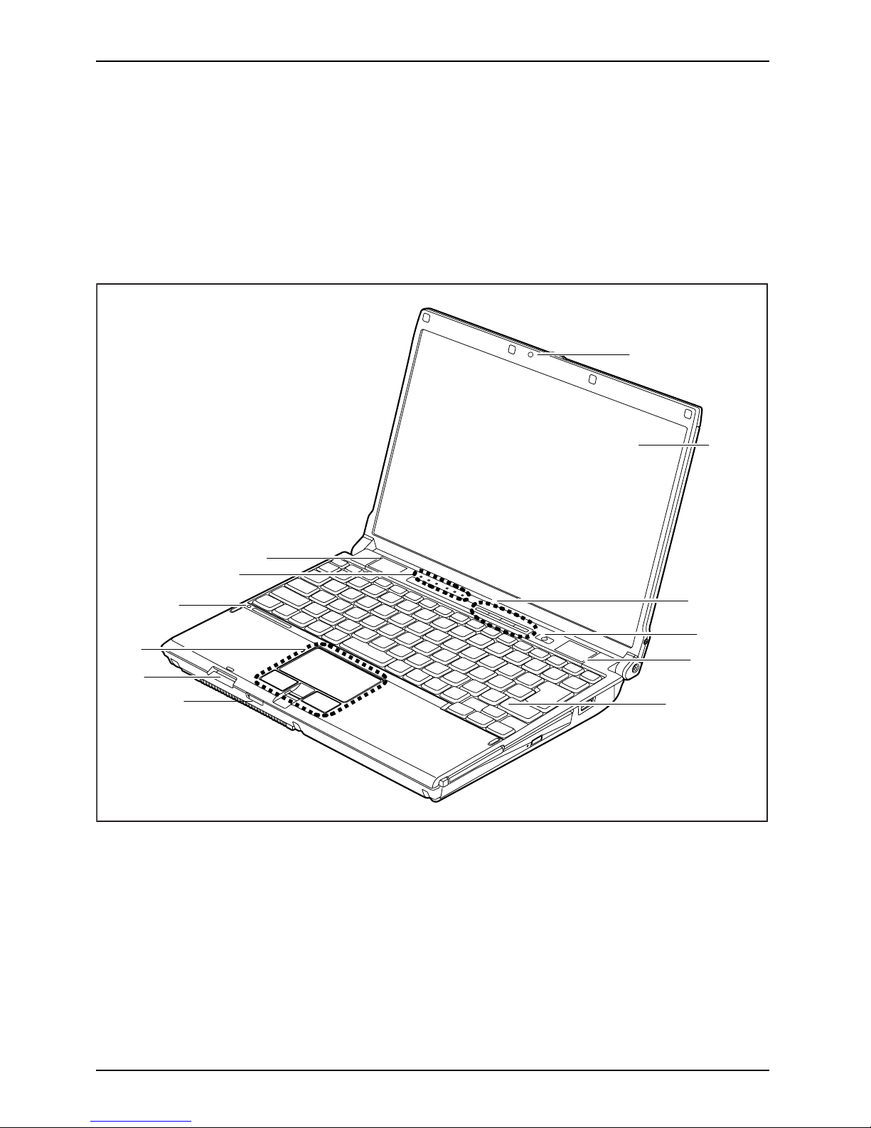
Notebook open
FrontViewLCDscreenScreenEasyLau nchkeysON/OFFswitchKeyboardRadiocomponentsON/OFFswitchSIMcardslotTouchpadTouchpadbuttonsFingerprintsensorMicrophoneLoudspeakerCamera
2
3
4
6
7
8
9
11
5
5
10
1
1=Camera
2 = LCD screen
3 = Easy Launch keys
4 = ON/OFF switch
5 = Loudspeaker
6 = Keyboard
7 = Radio components ON/OFF switch
8=SD-cardslot
9 = Touchpad with touchpad b uttons
and fingerprint sensor
10 = Microphone
11 = Status indicators
4 A26391-K212-Z220-1-7619, edition 1
Page 13

Ports and operating elements
Left-hand side
KensingtonLockDCinputjack(DCIN)MonitorportLANportUSBportFireWirepo rtMicrophonepor tHeadphoneport
1
2
3
4
5
6
7 8
9
1 = Kensington Lock
2 = DC input jack (DC IN)
3 = Monitor port
4 = LAN port
5=USBport
6 = USB port
7 = Fire Wire port
8 = Microphone port
9 = Headphone po rt
Right-hand side (variant with o ptical drive)
Ejectbutton,PCcardPCcardslotOpticaldriveCD/DVDdriveInsert/e jectbuttonUSBport
1
2
3
4
5
1 = Eject button, PC card
2 = PC card slot
3 = Optical drive
4 = Insert/eject bu tton
5 = USB port
A26391-K212-Z220-1-7619, edition 1 5
Page 14

Ports and operating elements
Right-hand side (variant w ith SmartCard reader)
Ejectbutton,PCcardPCcardslotOpticaldriveCD/DVDdriveUSBportSmartCar dreader
1
2
3
4
1 = Eject button, PC card
2=PCcardslot
3 = SmartCard reader
4 = USB port
Underside
BatteryMemorymodulesPortforportreplicator
1
2
3
1 = Battery
2 = Cover for memory modules
3 = Port for port replicator
6 A26391-K212-Z220-1-7619, edition 1
Page 15

Ports and operating elements
Switching on the notebook
1
► Open the LCD screen upwards (1).
1
► Press the ON /OFF switc
h (1) to switch
the notebook on.
The ON/O FF switch on the notebook
will be illuminated.
Windows XP
You can config
ure the power button with Start - (Settings) - Control Panel -
Performanc
e and Maintenance - Power Options - A dvanced.
Windows Vist
a
You ca n c on figu
re the power button with Start - (Settings) - Control
Panel - Mobil
e PC - Power Options.
If you have ass
igned a password, you must enter this when requested to do so, in order
to start the o
perating system. Further information can be found in the "Professional
Notebook" op
erating manual, section entitled "Security functions".
A26391-K212-Z220-1-7619, edition 1 7
Page 16

Ports and operating elements
Switching off the Notebook
► Close all applications and shut down your operating system (please
see operating system manual).
If the notebook cannot be shut down properly, press and hold the ON/OFF button for
approximately four seconds. The notebook will switch off. Any unsaved data may be lost.
The notebo ok is delivered with a protective film inserted between
the ke yboa rd and the LCD screen.
To ensure optimal protection of the LCD screen, it is recommended
that you insert this protective film between the keyboard and the LCD
screen each time you close t he notebook.
► Close the LCD screen.
8 A26391-K212-Z220-1-7619, edition 1
Page 17

Ports and operating elements
Status indicators
Statusindicators
The status indicators provide informa tion about the status of the power supply,
the drives and the keyboard functions.
Power indicator (ON/OFF switch)
Num Lock indica
tor
Hard disk indicator
Caps Lock indic
ator
Battery charging indicator
Scroll Lock in
dicator
Battery indicator
The meanings
of the symbols are as follows:
To avoid los
s of data, do not press the ON button while the hard disk indicator is lit up.
A26391-K212-Z220-1-7619, edition 1 9
Page 18

Ports and operating elements
Power indicator (ON/OFF switch)
• Indicator continuously lit: the notebook is switched on.
• Indicator flashes: the notebook is in suspend mode
• The indicator is not lit: the notebook is switched off or in Save-to-Disk mode.
Hard disk indicator
Indicator is on: the hard disk drive or the CD/DVD in the optical drive of the
notebook is being accessed.
Battery charging indicator
• The indicator is blue: The battery is already fully charged or the mains adapter
is connected but the battery is not installed.
• The indicator lights up orange: the battery is charging.
• Indicator flash es orange: Th e battery cannot be charged (the battery is too
cold or too hot for charging).
• The indicator is not lit up: the mains adapter is not connected .
Battery indicator
• Indicator lights up blue: The battery is charged to between 50% and 100% of
its capacity.
• The indicator lights up orange: The battery is charged to between 13% and
49% of its maximum capacity.
• The indicator lights up red: The battery is charged to between 0% and 12% of
its maximum capacity.
• The indicator flashes orang e while the battery is charging. (4 seconds after the
battery was installed.)
• Indicator flashes red: The battery cannot be charged.
• The indicator is not lit up: the battery is not installed.
Num Lock indicator
Indicator continuously lit: the
Num
key has been pressed. The virtual numeric
keypad is activated. You can output the characters indicated on the upper right of
the keys.
Caps Lock indicator
Indicator continuously lit: th
e Caps Lock key has been pressed. All the characters
you type will appear in upper cas
e. In the case of overlay keys, the character
printed on the upper left of the k
ey will appear when that key is pressed.
Scroll Lock indicator
Indicator continuously lit: the key combination
Fn+Scr
has been pressed. The
effect that this key has varies between applications.
10 A26391-K212-Z220-1-7619, edition 1
Page 19

Ports and operating elements
Key combinations
The following descrip tion of key combinations refers to functions when using
Microsoft Windows. Some of the following key combinations may not function in
other operating systems and with some device drivers.
Key combinations are entered as follows:
► Press and hold the first key in the co m bination.
► While holding the first key down, press the other key or keys in the combination.
The key combination
Ctrl
+
Alt Gr
or
Ctrl
+
Alt
canbeusedon
external keyboards that do not not feature a
Fn
key.
Sleep mode
Fn+F1Sleepmode
This key combination is used to activate the suspend mode (S3).
Enable/disable loudspeakers
Fn+F3LoudspeakersLoudspeakers
This key combination switches your notebook’s loudspeakers off and on.
An audible signal will be prod uced when the loudspeakers are switched on.
Switching the touchpad on/off
Fn+F4TouchpadLoudspeakers
This key combination enables and disables the touchpad.
Enlarge display
Fn+F5DisplayFull-screenmode
This key combination enlarges the scree n to the full-screen mode or switches
it back to the normal mode.
Decrease screen brightness
Fn+F6Screenbrightness
This key combination decreases the brightness of the screen.
Increase screen brightness
Fn+F7Screenbrightness
This key combination increases the brightness of the screen.
Decrease volume
Fn+F8Volume
This key combination reduces the volume of the integrated loudspeakers.
A26391-K212-Z220-1-7619, edition 1 11
Page 20

Ports and operating elements
Volu me increase
Fn+F9Volume
This key combination raises the volume of the integrated loudspeakers.
Toggle output screen
Fn+F10Toggleoutputscreen
If an external monitor is connected, the monitor on which the output is to be
displayed can be selected with this key combination.
You can opt to use:
• just the notebook’s LCD screen
• just the external monitor
• both the LCD screen and the external monitor
+
Ctrl
C
Halt current operation
Ctrl+C
This key combination can be used to hal
t an operation instan tly
without clearing the keyboard buff
er.
Switch betw een open applications
With this key combination you can switch between several open
applications.
Alt+Tab
AltCtrl
Del
SysRq
++
Perform warm boot
This key combination triggers a res
et and reboots t he notebook. First
press and hold both the
Ctrl
and
Alt
key, then
press the
Del
key. This will cause the Task Mana
ger to be displayed. The key
combination must be pressed a se
cond time to reboot the system.
Ctrl+Alt+DelWarmboot
Back tab
This key combination moves the curs
or back to the previous tabular
stop.
Shift+TabBacktab
Key combinations using the Windows keys are detailed in the ma nual
for your operating system.
12 A26391-K212-Z220-1-7619, edition 1
Page 21

Ports and operating elements
Application buttons
Applicationbuttons
Your noteb ook is equipped with four application keys.
E
Lock Workstation key
This key allows you to lock your workstation. However, you are also free to program
this key as desired.
Mobility Center key
This bu tton starts t
he Mobility Center. However, you are also free to program this
key as desired.
E key
TheEkeyisasimplewa
y of activating and deactivating power mana gement functions
(e.g. reducing scr
een brightness), refe r to the "Professional Not ebook" manual.
I key
TheIkeyallowsyout
o access further information about your notebook. However, you
arealsofreetoprog
ram this key as desired.
Programming the a
pplication keys
With the Application Panel you can assign various functions to the application keys.
Windows XP
You w i ll find the Application Panel under Start - (Settings) - Con t rol Panel - Additional
Control Panel Options - Application Panel.
Windows Vista
You wil l find the Application Panel under Start symbol - Programs - Lifebook Application Panel.
A26391-K212-Z220-1-7619, edition 1 13
Page 22
Ports and operating elements
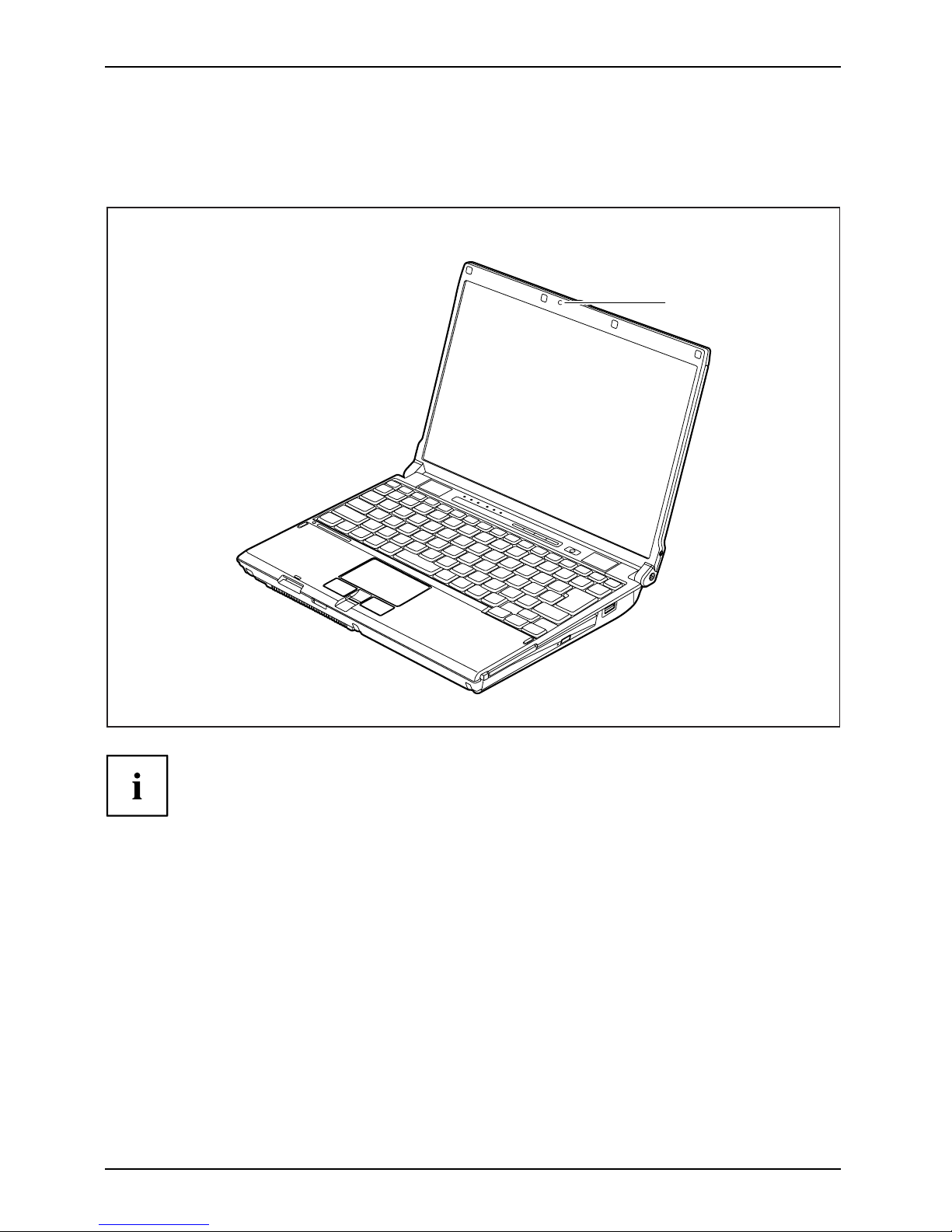
Camera
Your notebook is equipped with an integral webcam (1). Depending on the software used,
you can take pictures, record video clips or take part in web chats.
1
The webcam automatically adjusts itself to the current light level. For this reason
the LCD screen may flicker while the light level is adju sted.
The picture quality depends on the lighting conditions and the software being used.
You can only use the webcam with one piece of softwa re at a time.
When using the webcam the notebook su pport must not wobble.
Further information about using the camera can be found in the supplied software. If
you do not want to use the camera function, y ou can disable it in the BIOS.
14 A26391-K212-Z220-1-7619, edition 1
Page 23
Ports and operating elements
Removing and installing the bat
tery
NotesBattery
Only use rechargeable batteries approved by Fujitsu Technology
Solutions for your notebook.
Never use force when inserting or removing a battery.
Make sure that no foreign bodies get into the battery connections.
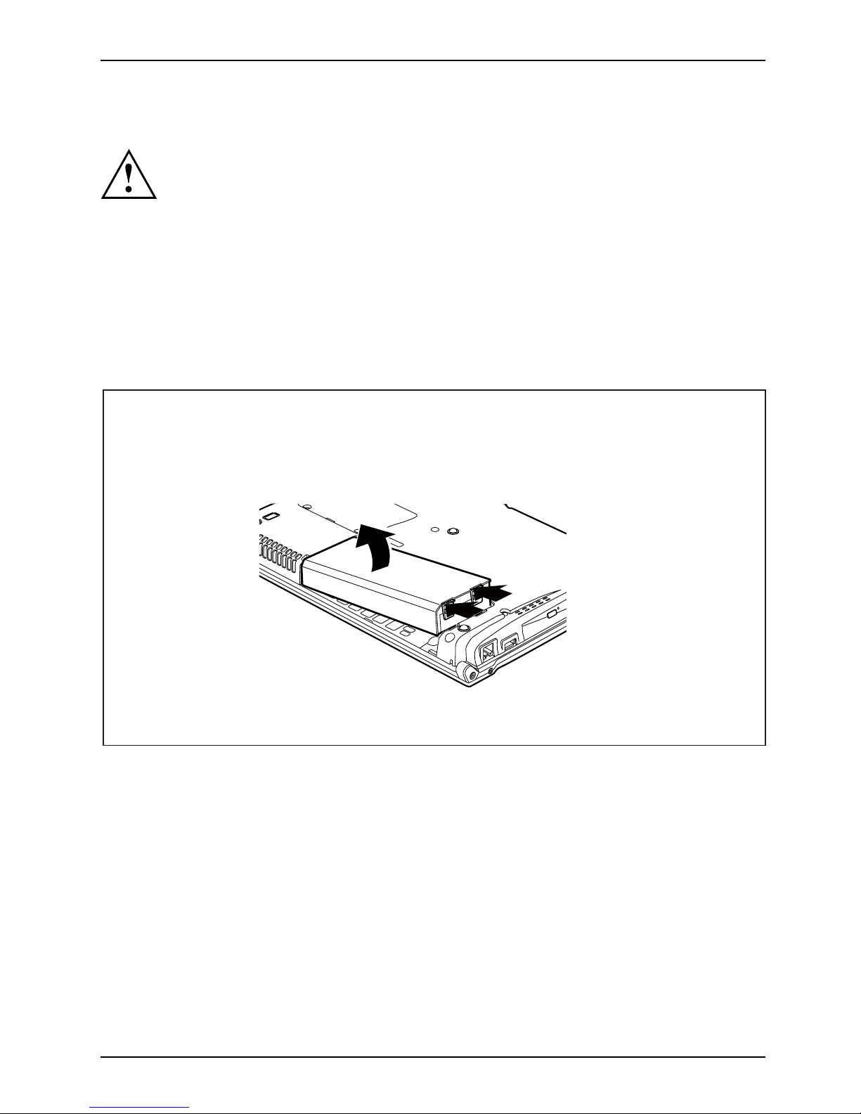
Removing the battery
► Switch the notebook off and pull the power plug out of the mains socket.
► Close the LCD screen.
► Disconnect all cables connecte d to the notebook.
► Turn your notebook over and place it o
n a stable, flat and clean surf ace. If necessary, lay
an anti-slip cloth on this surface t
o prevent th e notebook from being scratched.
1
1
2
► Press the two unlocking lugs (1), hold them down and lift the battery slightly.
► Remove the battery from the battery co m partm ent (2).
A26391-K212-Z220-1-7619, edition 1 15
Page 24
Ports and operating elements
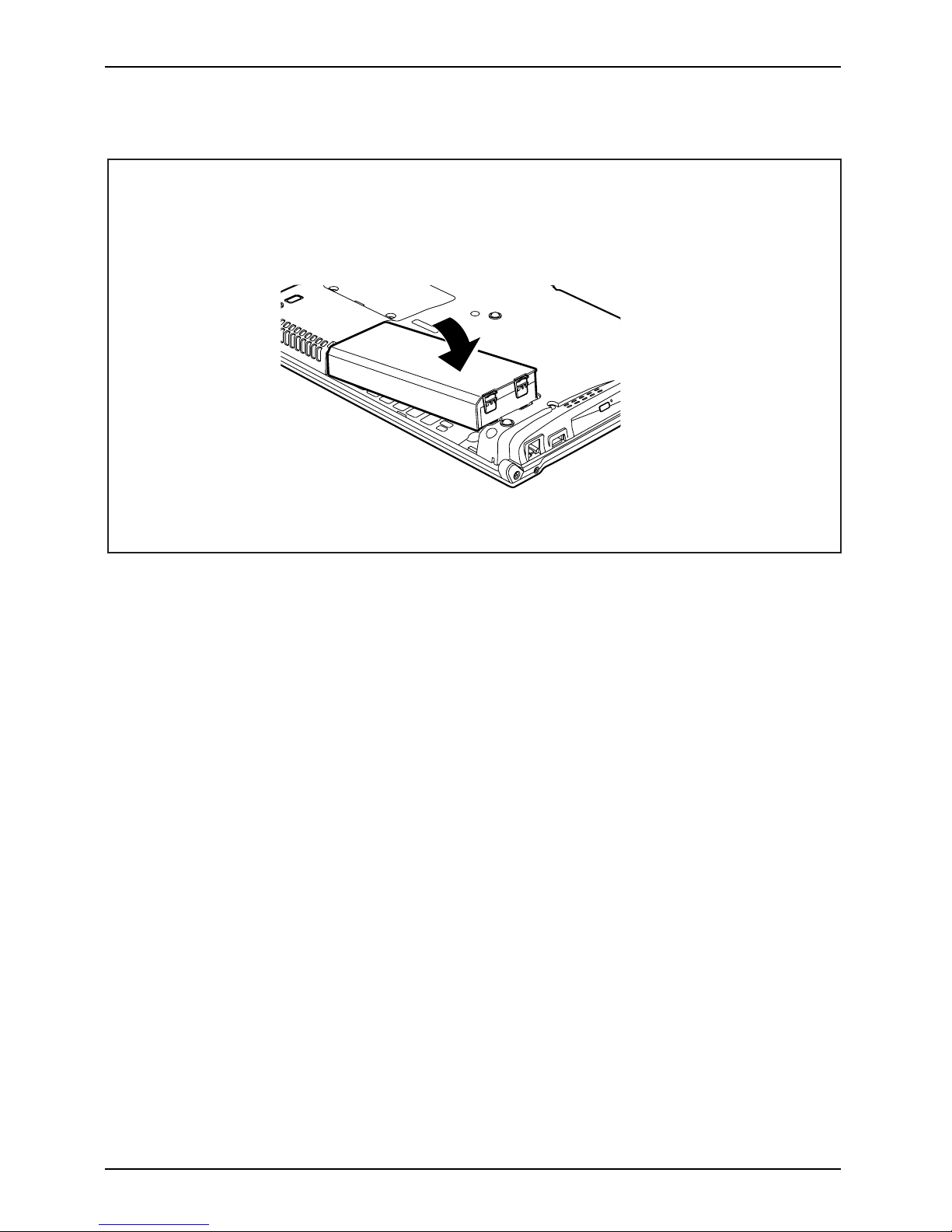
Installing battery
► Position the batte
ry at the edge.
► Push the battery into the battery compartment until you feel it engage.
16 A26391-K212-Z220-1-7619, edition 1
Page 25

Ports and operating elements
SIM card (optional)
Follow the instructions supplie d by the provider of the SIM card.
Inserting the SIM card
► Switch the notebook off and pull the power plug out of the mains socket.
► Close the LCD screen.
► Disconnect all cables connecte d to the notebook.
► Turn your notebook over and p la
ce it on a stable, sturdy, flat surface. If necessary, lay a
non-slip cloth on this s urfac
e to prevent the notebook from being scratched.
► Remove the battery (see Section "
Removing the battery", Page 15).
► If necessary, open the clip (a
)oftheSIMcard.
1
2
a
► Insert the SIM card into the slot so that
the the chip is facing upwards and the
angled edge is at the front right, facing
towards the slot (1). Ensure that you hear
the SIM card click into place.
► Slide the clip (a) of the SIM
card in the
direction of the arrow (2).
► Reinstall the battery (see "
Installing battery", Page 16).
► Turn the notebook the right way up and place it on a flat surface.
► Reconnect the cables that you disconnected previously.
A26391-K212-Z220-1-7619, edition 1 17
Page 26

Ports and operating elements
Removing a SIM card
► Switch the notebook off and pull the power plug out of the mains socket.
► Close the LCD screen.
► Disconnect all cables connected to the notebook.
► Turn your notebook over and place it on a stable, flat and clean surface. If necessary, lay
an anti-slip cloth on this surface to prevent the notebook from being scratched.
► Remove the battery (see Section "
Removing the battery", Page 15).
a
1
2
► Slide the clip (a) of the SI M card in the
direction of the arrow (1).
► Press on the edge of the SIM card so that
it jumps up slightly out of the slot.
► Pull the SIM card out of the slot in the
direction of the arrow (2).
► Reinstall the battery (see "
Installing battery", Page 16).
► Turn the notebook the right way up and place it on a flat surface.
► Reconnect the cables that you disconnected previously.
18 A26391-K212-Z220-1-7619, edition 1
Page 27

Ports and operating elements
Radio components: UMTS (optional)/wireless
LAN/Bluetooth
WirelessLANBluetoothUMTS
The installation of a wireless module not approved by Fujitsu Technology Solutions
GmbH will invalidate the approvals issued for this device (see "
Technical data", Page 26).
The modules for radio components are switched off during shipping.
Switching the radio components on and off
► Slide the ON/OFF switch into the "ON"
position to activate the radio components.
WirelessLANWirelessLA NBluetoothBluetooth
or
► Slide the ON/OFF switch to the
"OFF" position to deactivate the
radio components.
The Bluetooth and UMTS modules and the wireless LAN transmission unit (antenna)
will also be switched off when you switch off the radio compon ents.
You can also deactivate the wireless components individually in the BIOS Setup.You
must have assigned a supervisor password in order for this function to be available.
Pay attention to the additional safety notes for devices with radio
components provided in the "Safety" manual.
Details on using Wireless LAN can be found the online help system
included in the W ireless LAN software.
You c a n find more information on how to use Bluetooth on the CD you
received with your Bluetooth software.
You can obtain more information on UMTS from your service provider.
A26391-K212-Z220-1-7619, edition 1 19
Page 28
Ports and operating elements
Port Replicator (optional)
PortReplicator
The Port Replicator is a docking device that helps you to quickly co nnect a Fujitsu Technology
Solutions notebook to your peripheral devices, such as a monitor, printer etc.
Among other things, the Port Replicator is equipped with the standard ports
for monitor, audio, m ouse and keyboard.
You simply have to dock the notebook to work with your peripherals. There
is no need to connect additional cables.
For further information about th e Port Replicator and the different external
devices that can be connected to it, refer to the "Professional Notebook" manual,
in the section entitled "Connecting external devices".
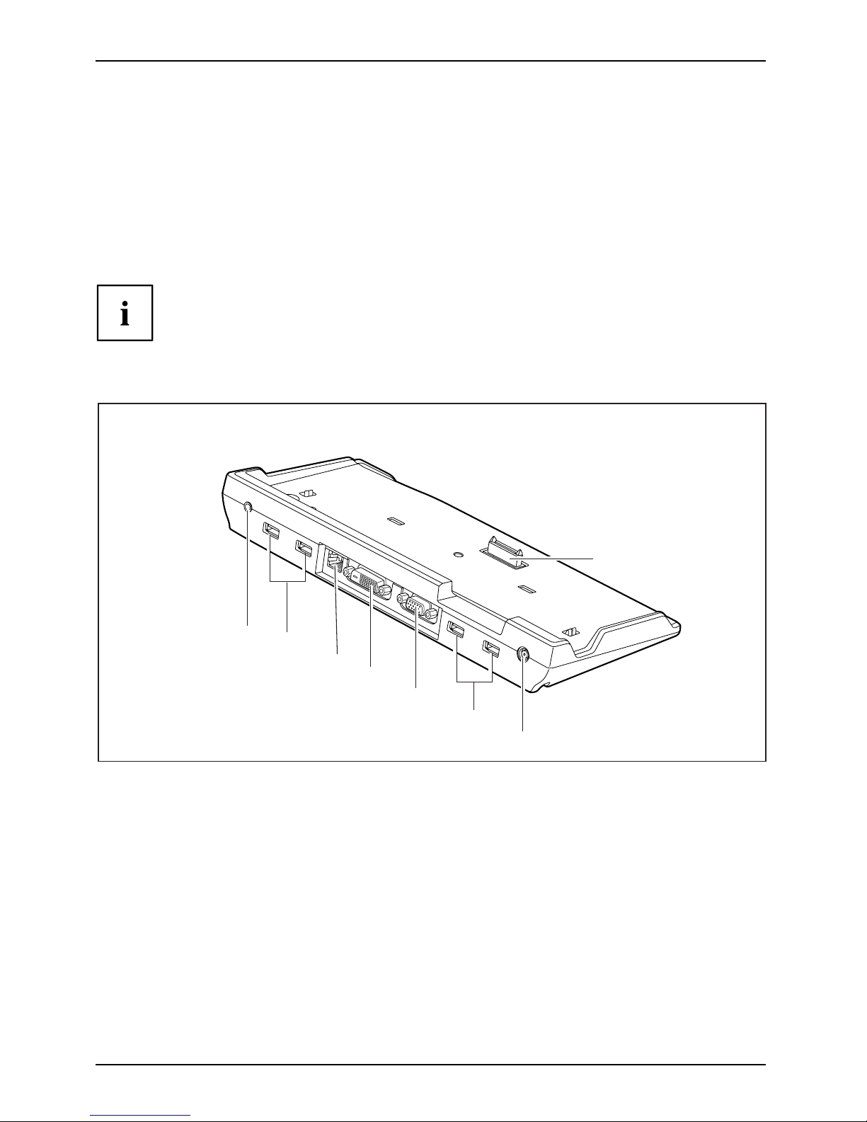
Ports on the Port Replicator
PortReplicatorPorts
1
2
3
4
5
2
6
7
1 = Audio output
2 = USB ports
3 = LAN port
4 = DVI port
5 = Monitor port
6 = DC input jack (DC IN)
7 = Connector on the Port Replicator for
the docking port on the underside
of the no tebook
20 A26391-K212-Z220-1-7619, edition 1
Page 29

Ports and operating elements
Connecting the notebook to the Port Replicator
The mains adapter must be connected to the Port Replicator when the notebook is
connected to the Port Replicator. Some ports will not function if this is not done.
We recommend that the notebook is not operated with the LCD screen
closed when the notebook is connected to the Port Replica tor. The resulting
overheating can lead to a loss of performance.
PortReplicator
► Position the notebook so that the docking port on the underside of the notebook
is aligned with the connector on the Port Replicator.
► Press down gently on the rear cor
ners of the notebook so that it locks into p osition.
Disconnecting the notebook from the Port Replicator
Problems may occur if the notebook is removed from the Port Replicator during
operation. We recommend that the notebook is switched off or that the appropriate
undocking function provided by the operating system is executed.
► Pull the release lever on the right hand side of the Port Replicator until
you hear the notebook unlock.
► Now lift the notebook from the Port Replicator.
A26391-K212-Z220-1-7619, edition 1 21
Page 30

Removing and installing components
during servicing
Removing and installing compo
nents
during servicing
Only qualified technicians should repair your notebook. Unauthorised
opening or incorrect repair may greatly endanger the user (electric shock,
fire risk) and will invalidate your warranty.
Components
Servicing
You m ay remove and install the compo nents described in this chapter yourself
after consulting the Hotline/Help Desk.
If you remove and install components without consulting the Hotline/Help
Desk, then the warranty of your notebook will be voided.
Notes on installing and removing boards
and components
• Switch the notebook off and pull the p ower plug out of the mains socket.
• Always remove the battery.
• Take care when you use the locking mechanisms on the battery and any other component.
• Never use sharp objects suc
h as screwdrivers, scissors or knives as leverage to remove covers.
NotesBoardESD
Boards with electrostatic sensitive devices (ESD) are marked with the label
shown.
When handling boards fitted with ESDs, you must always observe the following
points:
• You must always discharge static build up (e.g. by touching a grounded
object) before working.
• The equipment and tools you use must be free of static charges.
• Remove the power plug from the mains supply before inserting o r removing
boards containing ESDs.
• Always hold boards w ith ESDs by their edges.
• Never touch pin s or conductors on boards fitted with ESDs.
22 A26391-K212-Z220-1-7619, edition 1
Page 31

Removing and installing components
during servicing
Removing and installing memory
modules
MainmemoryMemoryexpansionMemoryupgradeSystemexpansion
The installation and removal of memory modules in one of the two slots
should only be carried out by an authorised technician.
The notebook will not start without memory modules, as no fixed RAM is installed.
Your notebook supports dual channel DDR3 technology.
The dual channel DDR3 technology can only be used with two identical memory
modules. When two different memory modules are installed, only "single channel"
mode is supported. This reduces the performance of your notebook.
With a memory configuration of 4 GBytes, the visible and usable
main memory may be reduced to 3 GBytes (depending on notebook
configuration and the operating system used).
If you are asked by the Hotline/Help Desk to remove and install the memory
modules yourself, proceed as follows:
Pay attention to the relevant safety notes provided in the "Important notes" chapter.
The notebo ok must be switched off when installing/removing the memory
modules, it must not be in Suspend mode.
Only use approved memory expansion modules in your notebook
(see Section "
Technical data", Page 26).
Never use force when installing or removing memory modules.
Make sure that foreign objects do not fall into the memory expansion compartment.
Individual components (e.g. t
he processor heat sink) can become very hot
during operation. Therefore
, we recommend that you wait one hour after
switching off the notebook b
efore removing or installing the memory modules.
Otherwise, there is a risk o
f suffering burns!
As some non -ESD safe compone
nts are exposed, please observe the s ection "
Notes
on install ing and removing
boards and components", Pa ge 22.
► Switch your notebook off and unplug the mains adapter from the mains outlet.
► Close the LCD screen.
► Disconnect all cables connecte d to the notebook.
► Turn your notebook over and place it on a stable, flat and clean surface. If n e cessary, lay
an anti-slip cloth on this surface to prevent the notebo ok from being scratched.
► Remove the battery (see "
Removing the battery", Page 15).
A26391-K212-Z220-1-7619, edition 1 23
Page 32

Removing and installing components
during servicing
Removing the cover
1
1
2
► Remove the screws (1).
► Lift the cover off the notebook (2).
Removing memory modules
3
2
1
1
► Carefully push the two mounting
clips outwards (1).
MemoryexpansionMemorymodule
The memory module snaps upwards (2).
► Pull the memory module out of its slot
in the direction of the arrow (3).
Installing a
memory module
2
a
1
► Insert the memory modu le with the contacts
and the recess (a) facing the slot (1).
Memory
expansion
Memory
module
► Carefully pu
sh the memory module
downwards un
til you feel it click
into place (2
).
24 A26391-K212-Z220-1-7619, edition 1
Page 33

Removing and installing components
during servicing
Attaching the cover
2
2
1
► Fold the cover in the direction of
the arrow (1).
► Secure the cover with the screws (2).
► Reinstall the battery (see "
Installing battery", Page 16).
► Turn the notebook the
right way up and place it on a flat surface.
► Reconnect the cables that you disconnected previously.
A26391-K212-Z220-1-7619, edition 1 25
Page 34

Technical data
Technical data
Notebook
Technicaldata
The installation and removal of memory modules in one of the two slots
should only be carried out by an authorised techn ician.
General
Processor
Intel
®
Core 2 Duo SU9400
Main memory
Max. 4 GB
2 slots: 1 GByte or 2 GByte - DDR3 6400
Electrical data
Regulations comp lied with
CE
Protection class II
Maximum power draw (with the notebook
switched on and the battery charging)
60 W
LCD screen
Screen size (diagonal) 12.1 inch WXGA (Wide XGA), TFT
Max. resolution
1280 x 800 / 16 million colours
Graphics card
Chip Intel GS45 + ICH9M SFF Cantiga SFF
Video memory (VRAM) Up to 358 MB (UMA)
Audio
Sound chip ALC262
Input devices
Keyboard 83 keys
Touchpad
2 keys and 1 fingerprint sensor
Slots
PC card slot (CardBus/PCMCIA) PCMCIA 1 x Type II
SIM card slot
1x
Network
LAN
Socket, RJ45
WLAN
PCIe half size
UMTS full size
Ports
Monitor port 15-pin socket
Microphone jack 3.5 mm mono mini-jack
Headphones port 3.5 mm stereo mini jack
FireWire port
S400, 4-pin
USB port 3 x USB 2.0
26 A26391-K212-Z220-1-7619, edition 1
Page 35

Technical data
Ports on the Port Replicator
DVI port
Monitor port 15-pin socket
LAN port
Socket, RJ45
USB port 4 x USB 2.0
Ambient conditions
Environment class (3K2) DIN IEC 721
Mechanical class (7M2) DIN IEC 721
Temperature
Operation 5 °C ... 35 °C
Transportation
-15 °C ... 60 °C
Dimensions
Width x depth x height 274.2 mm x 280.4 mm - 210.1 mm x 28.5 - 37.4
mm
Weight (depending on configuration)
approximately 1.2 kg with battery
The data sheet for this notebook contains further technical dat a. The data
sheet can be found on your notebook or on the Internet at "
http://ts.fujitsu.com"
or on the supplied "Drivers & Utilities" CD/DVD.
Battery
Technicaldata
4-cell rechargeable battery 6-cell rechargeable battery
Rated voltage 7.2 V 7.2 V
Rated capacity 5800 mAh 8700 mAh
The operating time depends on the device configuration, the active
applications and the energy saving settings.
Power adapter
Techn ic
aldata
Primary
Rated voltage
100 V or 240 V (automatic)
Rated frequency 50 Hz to 60 Hz (automatic)
Secondary
Rated voltage 16 V
Max. rated current 3.75 A
An additional mains adapter or power cable can be ord ered at any time.
A26391-K212-Z220-1-7619, edition 1 27
Page 36

Index
Index
A
Alt+Tab 12
Application buttons 13
B
Back tab 12
Battery 6
important notes 15
Bluetooth 19
Switching off 19
Switching on 19
Board 22
C
Camera 4
CD/DVD drive 5–6
Components
installing / removing 22
Ctrl+Alt+Del 12
Ctrl+C 12
D
DC input jack (DC IN) 5
Display
enlarge 11
E
Easy Launch keys 4
Eject button, PC card 5–6
ESD 22
F
Fingerprint sensor 4
FireWire port 5
Fn + F1 11
Fn + F10 12
Fn + F3 11
Fn + F4 11
Fn + F5 11
Fn + F6 11
Fn + F7 11
Fn + F8 11
Fn + F9 12
Front 4
Full-screen mode 11
H
Headphone port 5
I
Insert/eject button 5
K
Kensington Lock 5
Keyboard 4
L
LAN port 5
LCD screen 4
Loudspeaker 4
Loudspeakers
disable 11
enable 11
M
Main memory 23
Memory expansion 23
installing 24
removing 24
Memory module
installing 24
removing 24
Memory modules 6
Memory upg rade 23
Microphone 4
Microphone port 5
Monitor port 5
N
Notes
battery 15
boards 22
O
ON/OFF switch 4
Optical drive 5–6
P
PC card slot 5–6
Port for port replicator 6
Port Replicator 20
Connecting a notebook 21
Ports 20
Ports 4
Port Replicator 20
28 A26391-K212-Z220-1-7619, edition 1
Page 37

Index
R
Radio components ON/OFF switch 4
S
Screen 4
Screen brightness
decrease 11
increase 11
Servicing 22
Shift+Tab 12
SIM card slot 4
Sleep mode
activating 11
SmartCard reader 6
Status indicators 9
System expansion
memory expansion 23
T
Technical data
battery 27
Mains adapter 27
Notebook 26
Toggle output screen 12
Touchpad 4
disable 11
Touchpad buttons 4
U
UMTS 19
USB port 5–6
V
View
front 4
Volume
decrease 11
increase 12
W
Warm b oot 12
Wireless LAN 19
Switching off 19
Switching on 19
A26391-K212-Z220-1-7619, edition 1 29
 Loading...