

Page 1

Copyright
Fujitsu Limited has made every effort to ensure the accuracy and completeness of this document. However,
as ongoing development efforts are continually improving the capabilities of our products, we cannot guarantee the accuracy of the contents of this document. We disclaim liability for errors, omissions, or future
changes.
LifeBook is a trademark of Fujitsu Limited.
Microsoft, Windows, MS, MS-DOS, and Windows NT are registered trademarks of the Microsoft Corporation of the United States in the United States and other countries.
Crusoe™ is a registered trademark of the Transmeta™ Corporation of the United States.
ATI is a registered trademark of ATI Technologies INC
Phoenix is a registered trademark of Phoenix Technologies Corporation of the United States.
K56flex is a trademark of Rockwell International Corporation and Lucent Technologies Corporation.
Other product names are trademarks or registered trademarks of their respective companies.
Other products are copyrighted by their companies.
Copyright© 1981-1999 Microsoft Corporation, All rights reserved.
Copyright© 1999 Phoenix Technologies, Ltd., All rights reserved.
All other products are trademarks or registered trademarks of their respective companies.
© Copyright 2002 Fujitsu Limited. All rights reserved. No part of this publication may be copied, reproduced,
or translated, without the prior written consent of Fujitsu Limited. No part of this publication may be stored
or transmitted in any electronic form without the written consent of Fujitsu Limited.
Operations are subject to the following two conditions:
(1) This device may not be allowed to cause harmful interference,
(2) This device must accept any interference received, including interference that may cause undesired
operation.
Website : www.fujitsu-pc-asia.com
Page 2

IMPORTANT SAFETY INSTRUCTIONS
1. Read these instructions carefully. Save these instructions for future reference.
2. Follow all warnings and instructions marked on the product.
3. Unplug this product from the wall outlet before cleaning. Do not use liquid cleaners or aerosol cleaners.
Use a damp cloth for cleaning.
4. Do not use this product near water.
5. Do not place this product on an unstable cart, stand, or table. The product may fall, causing serious
damage to the product.
6. Slots and openings in the cabinet and the back or bottom are provided for ventilation; to ensure reliable
operation of the product and to protect it from overheating, these openings must not be blocked or
covered. The openings should never be blocked by placing the product on a bed, sofa, rug, or other
similar surface. This product should never be placed near or over a radiator or heat register, or in a builtin installation unless proper ventilation is provided.
7. This product should be operated from the type of power indicated on the marking label. If you are not
sure of the type of power available, consult your dealer or local power company.
8. This product is equipped with a 3-wire grounding-type plug, a plug having a third (grounding) pin. This
will only plug into a grounding-type power outlet. This is a safety feature. If you are unable to insert the
plug into the outlet, contact your electrician to replace your obsolete outlet. Do not defeat the purpose
of the grounding-type plug.
9. Do not allow anything to rest on the power cord. Do not locate this product where persons will walk on
the cord.
10. If an extension cord is used with this product, make sure that the total ampere rating of the equipment
plugged into the extension cord does not exceed the extension cord ampere rating. Also, make sure
that the total rating of all products plugged into the wall outlet does not exceed 15 amperes.
11. Never push objects of any kind into this product through cabinet slots as they may touch dangerous
voltage points that could result in a fire or electric shock. Never spill liquid of any kind on the product.
12. Do not attempt to service this product yourself, as opening or removing covers may expose you to
dangerous voltage points or other risks. Refer all servicing to qualified service personnel.
13. Unplug this product from the wall outlet and refer servicing to qualified service personnel under the
following conditions:
a. When the power cord or plug is damaged or frayed.
b. If liquid has been spilled into the product.
c. If the product has been exposed to rain or water.
d. If the product does not operate normally when the operating instructions are followed. Adjust
only those controls that are covered by the operating instructions since improper adjustment of
other controls may result in damage and will often require extensive work by a qualified tech-
nician to restore the product to normal condition.
e. If the product has been dropped or the cabinet has been damaged.
f. If the product exhibits a distinct change in performance, indicating a need for service.
14. CAUTION. When replacing the battery, be sure to install it with the polarities in the correct posi-
tion. There is a danger of explosion if the battery is replaced with an incorrect type or is mistreated. Do not recharge, disassemble or dispose of in fire. Replace only with the same or equivalent type recommeded by the manufacturer. Dispose of the used battery according to the manufacturer’s instructions.
15. Use only the proper type of power supply cord set (provided in your accessories box) for this unit. It
should be a detachable type: UL listed/CSA certified, BS1363,ASTA,SS145 certified, rated 10A 250V
minimum, VDE approved or its equivalent. Maximum length is 15 feet (4.6 meters).
Page 3

High Safety Required Use
This Product is designed, developed and manufactured as contemplated for general use, including
without limitation, general office use, personal use, household use and ordinary industrial use, but is
not designed,developed and manufactured as contemplated for use accompanying fatal risks or
dangers that, unless extremely high safety is secured, could lead directly to death, personal
injury,severe physical damage or other loss (hereinafter ‘High Safety Required Use’), including without
limitation, nuclear power reactioncore control in nuclear atomic facility, airplane automatic aircraft
flight control, air traffic control, operation control in mass transport control system,medical instrument
for life support system, missile launching control in weapon system. You shall not use this Product
without securing the sufficient safety required for the High Safety Required Use.
Page 4

Data Storage Media
and Customer Responsibilities
The only effective protection for the data stored in a computer,such as on a hard disk,is for you,
Purchaser to regularly back up the data.Fujitsu and its affiliates,suppliers,service providers and
resellers shall not be responsible for any software programs,data or other information stored or
used on any media or part of any Product returned to Fujitsu or its service providers for Warranty
Service or other repair,including but not limited to the costs of recovering such programs,data or
other information.It is solely your responsibility as the Purchaser to back up any software programs,
data,or information stored on any storage media or any part of a Product returned for Warranty
Service or repair to the designated service centers.
Page 5

AUSTRALIAN WARNINGS
WARNING
FOR SAFETY REASONS, ONLY CONNECT EQUIPMENT WITH A TELECOMMUNICATIONS
COMPLIANCE LABEL. THIS INCLUDES CUSTOMER EQUIPMENT PREVIOUSLY LABELLED
PERMITTED OR CERTIFIED.
Connection of Non Certified/Approved peripherals may result in the equipment operating
outside the Australian EMI Standards.
Modems connected to the Australian telecommunications network must be operated in accordance with the
Labelling Notice. This modem has been specifically configured to ensure compliance with the ACA Standards.
Do not adjust your modem or software outside the values indicated below. To do so would result in your
modem being operated in a non-compliant manner.
Call Attempts/Retries:
Applications software shall be configured so that no more than 3 attempts are made to establish a connection
to a given number (Note: if the modem can detect service tones, up to 10 attempts can be made). If the call
sequence is unsuccessful, there shall be a delay of at least 30 minutes before attempting to call the number
again.
Failure to set the modem, and any application software used with the modem, to the values shown above
will result in the modem being operated in a non-compliant manner. Consequently, this would be in violation
of the Labelling Notice for this equipment, and the Telecommunications Act 1997 prescribes penalties for
the connection of non-compliant equipment.
Page 6

NEW ZEALAND WARNINGS
The grant of a Telepermit for any item of terminal equipment indicates only that Telecom has accepted
that the item complies with minimum conditions for connection to its network. It indicates no endorsement
of the product by Telecom, nor does it provide any sort of warranty. Above all, it provides no assurance
that any item will work correctly in all respects with another item of Telepermitted equipment of a different
make or model, nor does it imply that any product is compatible with all of Telecom’s network services.
This equipment is not capable under all operating conditions of correct operation at the higher speeds
for which it is designed. 56 KBPS connections are likely to be restricted to lower bit rates when connected
to some PSTN implementations. Telecom will accept no responsibility should difficulties arise in such
circumstances.
Immediately disconnect this equipment should it become physically damaged, and arrange for its
disposal or repair.
This equipment shall not be used in any manner, which could constitute a nuisance to other Telecom
customers.
This equipment shall not be set to make automatic calls to the Telecom “111” Emergency Service.
This device is equipped with pulse dialing while the New Zealand standard is DTMF tone dialing. There
is no guarantee that Telecom lines will always continue to support pulse dialing. It is strongly
recommended that pulse dialing is not used.
Some parameters required for compliance with Telecom’s Telepermit requirements are dependent on
the equipment (PC) associated with this device. The associated equipment shall be set to operate
within the following limits for compliance with Telecom’s Specifications:
For repeat calls to the same number.
There shall be no more than 10 call attempts to the same number within any 30 minute period
for any single manual call initiation, and
The equipment shall go on-hook for a period of not less than 30 seconds between the end of
one attempt and the beginning of the next attempt.
For Automatic calls to different numbers.
The equipment shall go on-hook for a period of not less than 5 seconds between the end of one
attempt and the beginning of the next attempt.
For Automatically answered Incoming Calls
Incoming calls shall be answered between 3 and 30 seconds from the start of the ringing.
For correct operation, the total of the RNs of all devices connected to a single line at anytime should not
exceed 5. The RN of this Equipment is 0.5.
WARNING
Connection of Non Certified/Approved peripherals may result in the equipment operating
outside the New Zealand EMI Standards.
Page 7
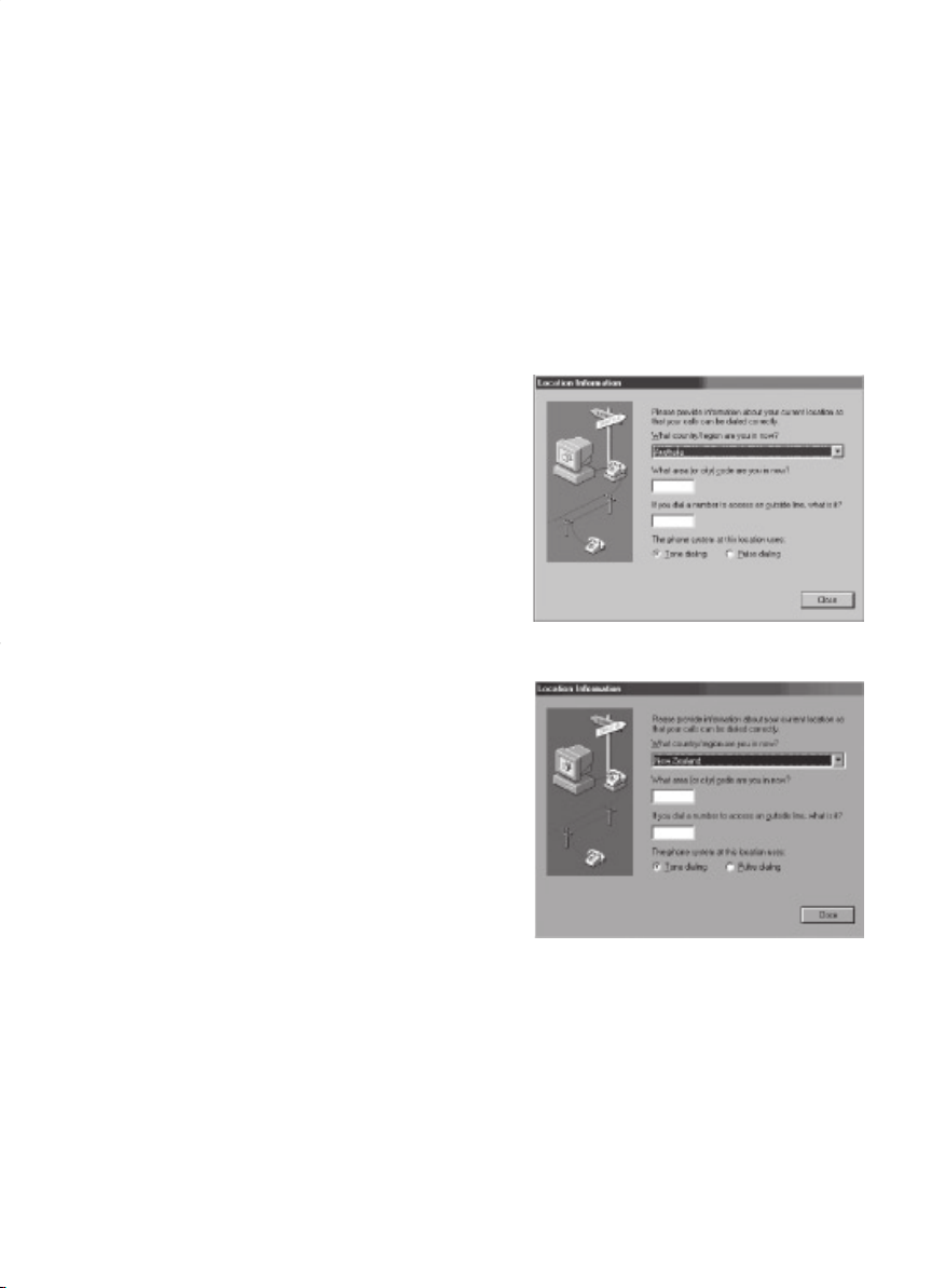
Note: Modem setting in Windows 98 / Windows Me
The default modem setting in Windows 98 / Windows Me operating system is United States of
America. If you are residing in Australia or New Zealand, please choose the appropriate country
where you are located.
The Modem will only operate with Tone Dialing; Selection of Pulse dialing is not possible.
Please see below instruction for quick modem setup.
A. If you are located in Australia
1. Go to Control panel, select modem icon.
2. Choose Australia in “What country/region
are you in now?”
3. Select Phone system as “Tone Dialing”
4. Close
B. If you are located in New Zealand
1. Go to Control panel, select modem icon.
2. Choose New Zealand in “What country/
region are you in now?”
3. Select Phone system as “Tone Dialing”
4. Close
Note:
Please check with your local distributor for the availability of Win Me and Win 98SE support.
Page 8
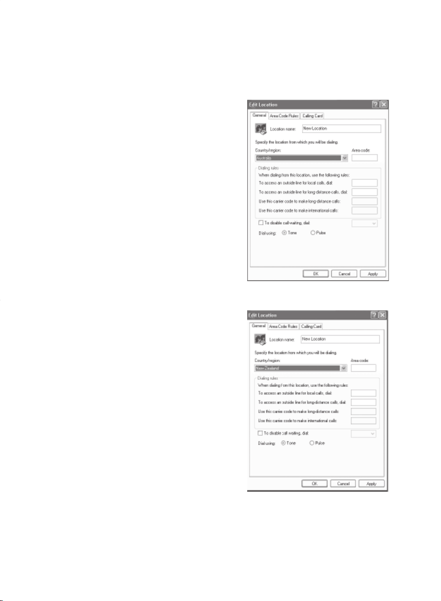
Note: Modem setting in Windows XP
A. If you are located in Australia
1. Click Start select Control panel select "Phone and
Modem Options".
2. Double click New Location.
3. Choose "Australia" in Country/region pull down
menu bar.
4. Select Phone system as “Tone Dialing”.
5. Click OK and Apply.
B. If you are located in New Zealand
1. Click start select Control panel select "Phone and
Modem Options".
2. Double click New Location.
3. Choose "New Zealand" in Country/region pull down
menu bar.
4. Select Phone system as “Tone Dialing”.
5. Click OK and Apply.
Note:
The screens and illustrations shown in this examples may slightly vary depending on the operating
environment that you have installed.
Page 9
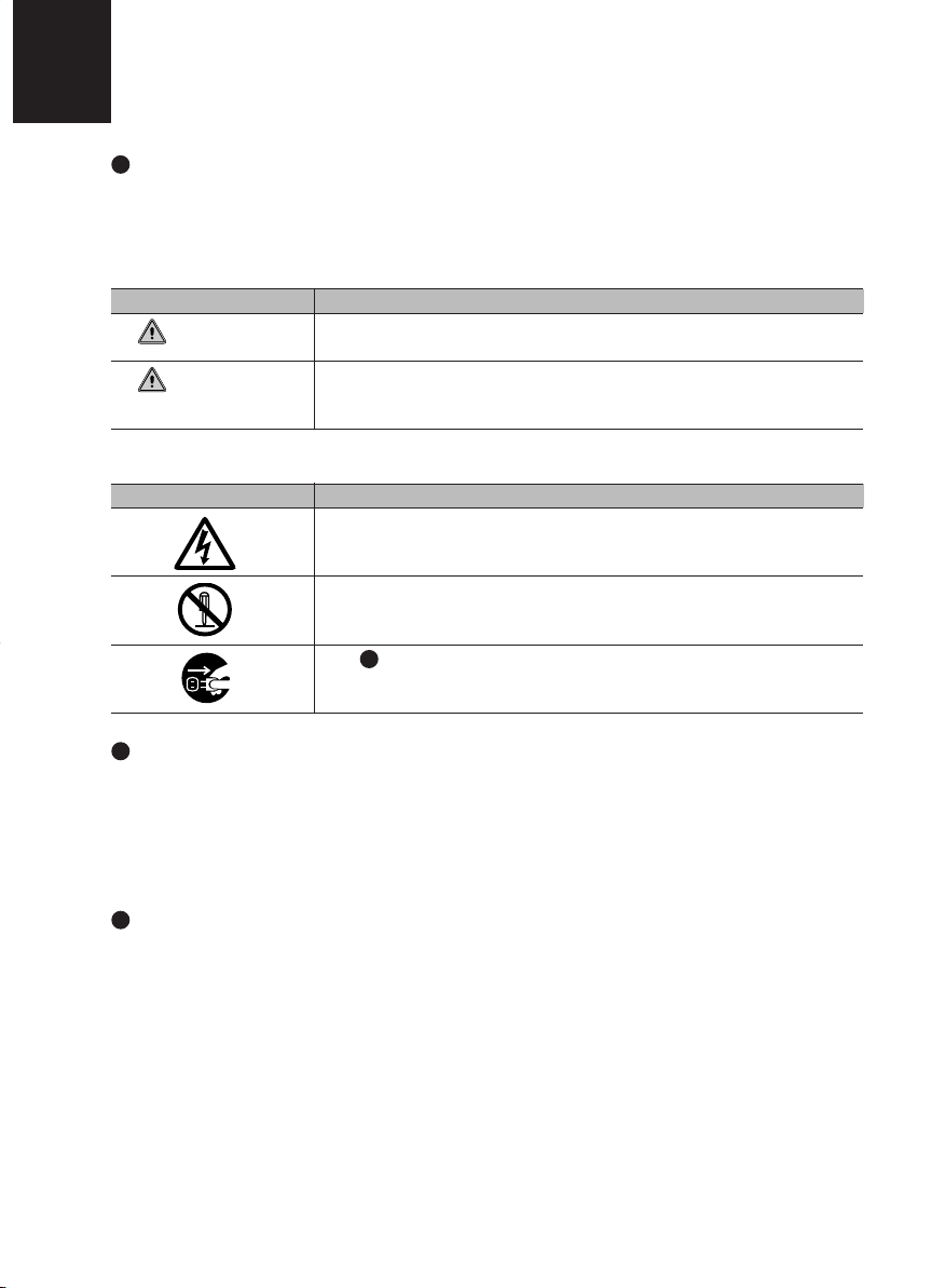
NOTATION IN THIS DOCUMENT
Warnings
This manual uses a variety of icons as visual marks so that you can use this computer safely and
correctly and avoid damage and danger to yourself and to others. These icons and their meanings
are as follows. Please learn these icons before reading this manual. Learning these icons will be
useful for understanding this manual.
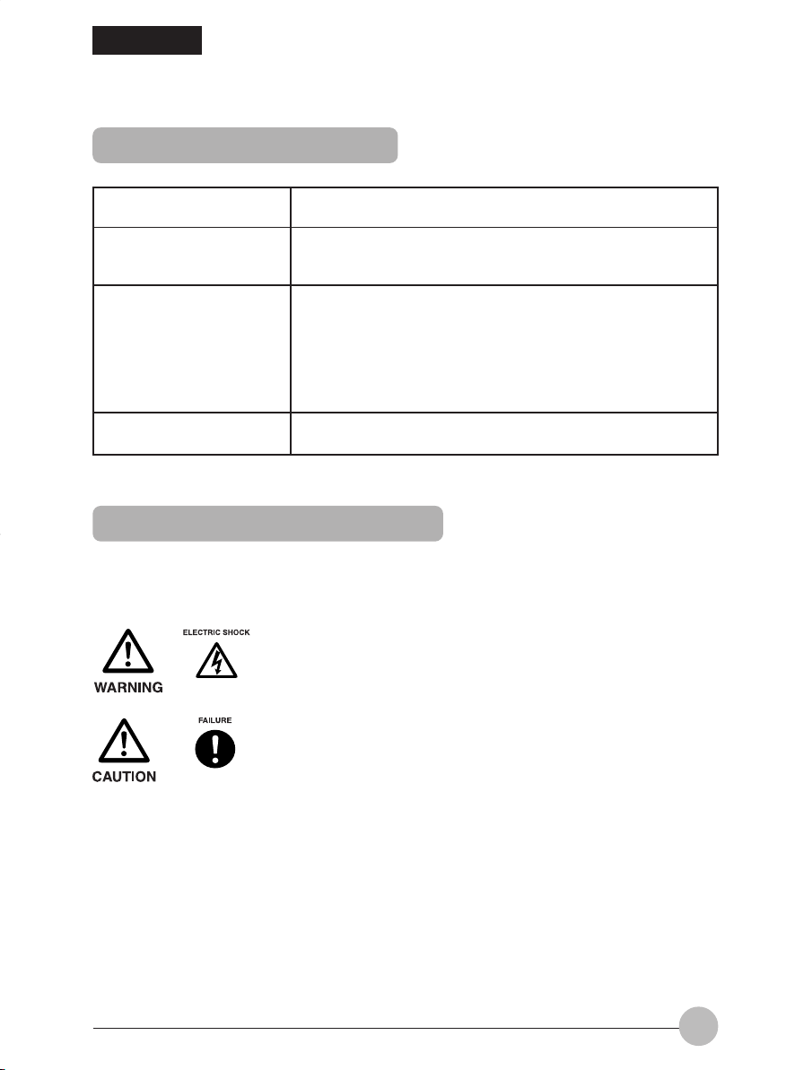
Icon Meaning
WARNING
CAUTION
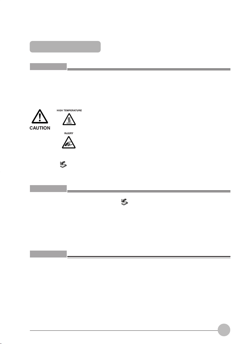
The symbols below are used together with the icons above to indicate what type of danger or
damage is involved.
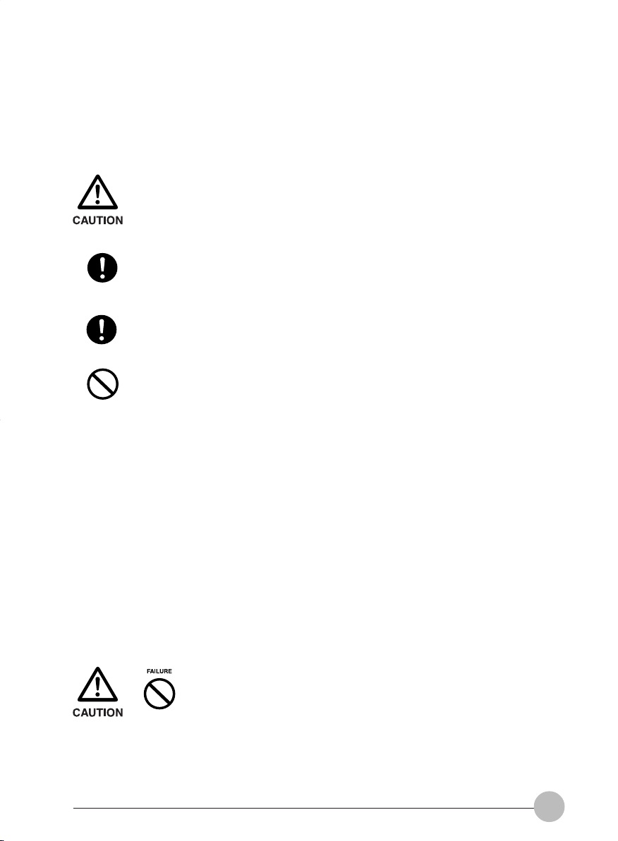
Symbol Meaning
Incorrect handling or ignoring this warning can cause a dangerous
situation that could result in death or severe injury.
Incorrect handling or ignoring this warning can cause a dangerous
situation that could result in moderate or minor injury or could result in
equipment damage.
The symbol indicates a w arning or caution. The symbol inside the
indicates the concrete nature of the warning. (The example on the left
is a caution for electric shock.)
The circle and slash indicates prohibited behavior. The symbol inside
the circle indicates the concrete nature of the prohibition. (The
example on the left indicates that disassembly is prohibited.)
The indicates instructions that must be followed. The symbol inside
indicates the concrete nature of those instructions. (The example on
the left tells you to unplug the power plug from the socket.)
Key notation and operation methods
Explanations of key operations do not show all the characters on the keyboard. Instead they
indicate just the keys necessary to the explanation as follows.
Examples: [Ctrl] key, [Enter] key, [ → ] key
When multiple keys are to be pressed at the same time, this is indicated by connecting them with
[+].
Examples: [Ctrl] + [F3] keys; [Shift] + [ ↑ ] key
Screen examples
The screens shown in this manual are examples. Please understand that the file names and
screens you use may be different.
Page 10

Notation in text
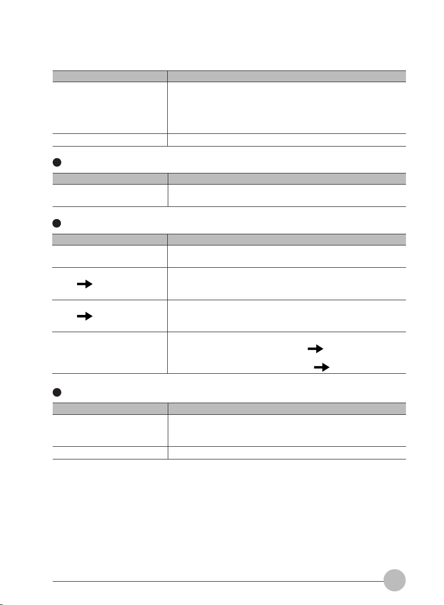
Here is what symbols in text mean.
Symbol Meaning
Critical Points
Indicates a point necessary for correctly operating the hardware or
software.
Gives the meaning and brief explaination of a term.
Column
→ Indicates the page to see elsewhere in this manual.
Command input (key input)
Within the text of this manual, command input (giving commands to the computer by pressing
keys) is indicated as follows.
Example:
In the position indicated in the example above by the ↑, the space left between the characters
indicates that a space needs to be left in the entry by pressing the space bar (the long key with
nothing written on it at the center of the front of the keyboard). Commands are written in this
manual as lowercase latin letters, but uppercase letters may be used.
Product names
The following product names are abbreviated as follows in this manual.
“Microsoft® Windows XP® operating system” is written as “Windows XP”.
“Microsoft® Windows® 98 operating system” is written as “Windows 98”.
“Microsoftt® Millennium® Edition operating system” is written as “Windows Me”
“Microsoft® MS-DOS® operating system Version 6.2/V” is written as “MS-DOS”.
“Microsoft® Windows® operating system Version 3.1” is written as “Windows 3.1”.
“Microsoft® Windows NT® Server network operating system Version 3.5” and “Microsoft® Windows
NT® Workstation operating system Version 3.5” are both written as “Windows NT 3.5”.
“Microsoft® Windows NT® Server network operating system Version 3.51” and “Microsoft® Windows
NT® Workstation and NT Server Version 4.0” are both written as “Windows NT 4.0”.
“Windows NT 3.51” and “Windows NT 4.0” are both written as Windows NT.
“Fujitsu LifeBook” is written as “this computer” or “the computer main unit”.
dir c:
↑
Page 11

Configuration of this Manual
SECTION 1
This section explains basic operations and basic items for using this computer, including the
names of the parts and their functions, quick point IV operation methods and battery operation.
SECTION 2
This section explains installation of options for this computer.
SECTION 3
This section explains what to do when trouble occurs with this computer and when messages are
displayed. Read this section as the necessity arises.
SECTION 1
SECTION 2
SECTION 3
Page 12

CONTENTS
SECTION 1
1. Names and Functions of the Parts ...................................... 2
Front features of the computer ............................................................ 2
Left/right features of the computer ...................................................... 4
Rear features of the computer ............................................................. 6
Bottom features of the computer ......................................................... 7
2. Status Indicator LCD............................................................. 8
3. Using Quick Point IV ...........................................................10
Quick Point IV .................................................................................... 10
How to use Quick Point IV ................................................................. 11
Using the scrolling function ............................................................... 12
4. Replacing the Internal Battery Pack ..................................13
Preparing necessary items ................................................................ 13
Replacing the internal battery pack ................................................... 13
5. E-mail Button .......................................................................15
6. About the Internal Modem ..................................................17
Connecting a modular cable .............................................................. 17
Caution in using the internal modem ................................................. 18
Charging ............................................................................................ 19
Using the computer with the battery .................................................. 19
Checking the remaining battery power .............................................. 20
If the battery is weak ......................................................................... 21
Notes on the battery .......................................................................... 22
7. Using a LAN .........................................................................23
Preparing necessary items ................................................................ 23
Connecting a LAN cable .................................................................... 24
8. Exterior Features................................................................. 26
Keyboard ........................................................................................... 26
About the ten-key mode .................................................................... 29
Page 13

SECTION 2
SECTION 3
1. Before Connecting Peripherals .......................................... 32
2. Connecting a Mouse ...........................................................33
Connecting a USB mouse ................................................................. 33
Disabling Quick Point IV .................................................................... 33
3. Connecting a USB Device .................................................. 34
Preparing necessary items ................................................................ 34
Connecting a USB device.................................................................. 35
4. PC Cards .............................................................................. 36
Notes on using PC Cards .................................................................. 36
Caution in using PC cards ................................................................. 37
PC cards that can be used with your computer ................................. 37
Preparing necessary items ................................................................ 37
Caution in using PC cards ................................................................. 38
Ejecting a PC card ............................................................................. 39
5. Connecting an External Display.........................................41
Preparing necessary items ................................................................ 41
Connecting an external display ......................................................... 41
1. When This Happens ............................................................ 46
2. Care and Maintenance ........................................................50
3. Glossary ...............................................................................55
Page 14

SECTIONSECTION
SECTION
SECTIONSECTION
SECTIONSECTION
SECTION
SECTIONSECTION
11
1
11
11
1
11
This section explains basic
operations and basic items for
using this computer, including
the names of the parts and their
functions, quick point IV
operation methods and battery
operation.
SECTION 1
SECTION 1
Page 15
SECTION 1
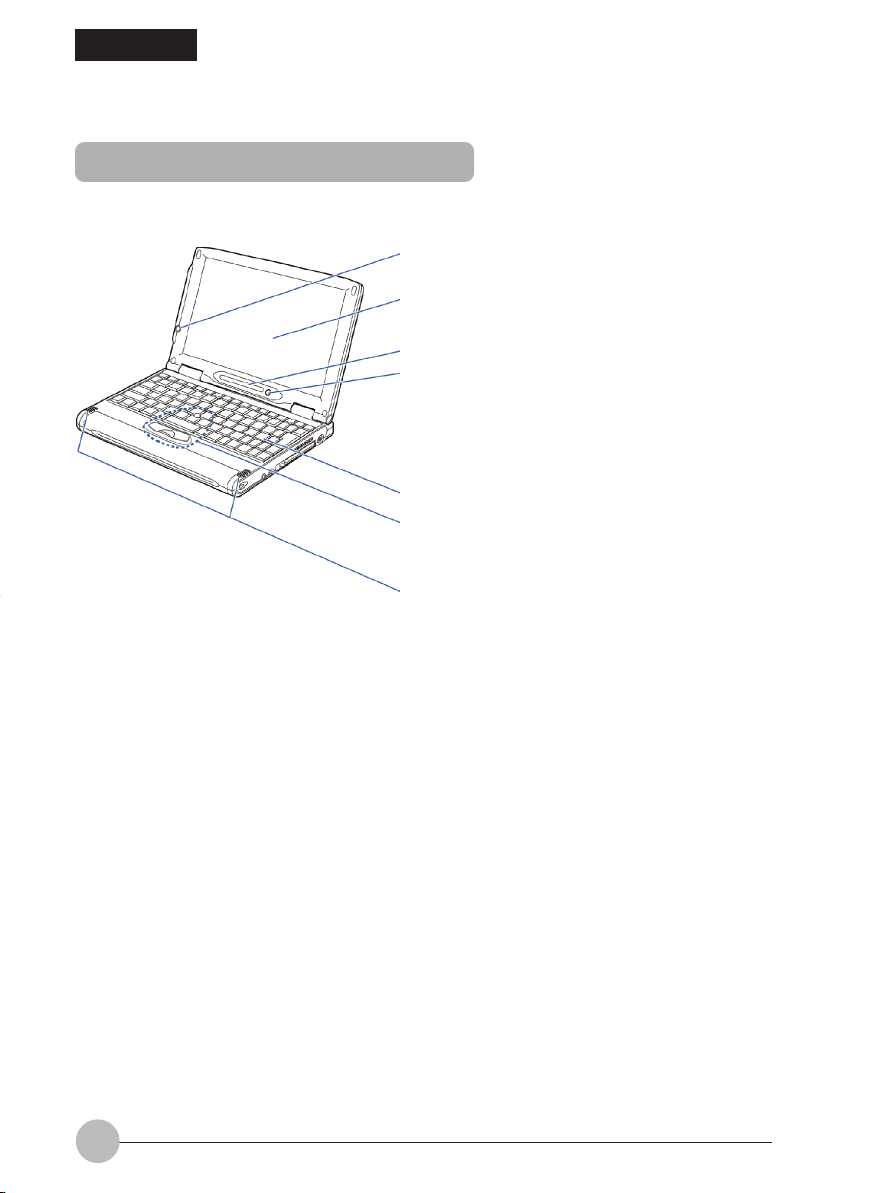
1. Names and Functions of the Parts
Front features of the computer
1
2
3
4
5
6
7
1 E-mail button
Once touch button to launch your email appliaction.
2 LCD display
The monitor of your computer.
2
Page 16

Critical Point
• About the characteristics of LCD displays
For reasons of characteristics specific to LCD displays, the f ollowing phenomena ma y occur but
they are not defects in your LCD display.
– The TFT color liquid crystal display (LCD) of you computer consists of more than 1,840,000
pixels (dots) (if the resolution is 1024x600), which are arranged in rows and columns
through the utilization of high-level technology. For technical reasons, how ev er , some dots
on your LCD display may not light up or be always lit, but this does not mean that the
display is defective.
– There may be a slight difference in color between your LCD display and another LCD
display because of differences in manufacturing condition. Moreover, your LCD display
may produce colors somewhat unevenly because of temperature changes, etc.
3 Status indicator LCD
Displays the operating status of the computer.
4 SUS/RES (Suspend/Resume) switch
Used to turn on your computer, to put it into standby (suspending oper ation) mode, or to resume
system operation.
5 Keyboard
Allows you to type in letters and figures and to give commands to the computer.
6 Quick Point IV
Used to control the mouse pointer.
7 Speakers
A sound output device of the computer.
3
Page 17
Left/right features of the computer
Left panel of the computer
1
1 Incoming mail LED
If you press the E-mail button, this LED will turn on while the computer is checking whether there
is an E-mail.
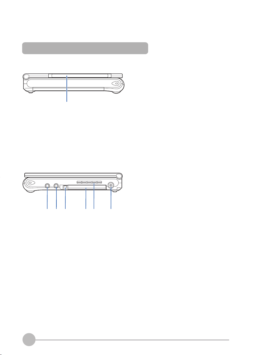
Right panel of the computer
123 45 6
4
Page 18
1 Headphone jack
Used to connect commercially available headphones (with a f3.5-mm mini plug). Headphones
with some types of plugs cannot be connected. So before purchasing headphones, make sure
they are compatible with your computer.
HEARING LOSS
– Turn the sound volume le v el of the computer to the minimum prior to connection to the
headphone or microphone jack. Failure to do so may result in the equipment being
damaged and/or your hearing being adversely affected.
– Don’t raise the volume too high especially when you are listening with headphones.
Listening to very loud sound for a long time could impair your hearing.
– Don’t turn on or off the computer while you are wearing headphones, or noise could
impair your hearing.
2 Microphone jack
Used to connect a commercially available monaural microphone (with a f3.5-mm mini plug) for
sound recording.
Some types of microphones (e.g., dynamic microphones) cannot be used with your computer.
So before purchasing a microphone, make sure it is compatible with your computer.
3 PC card eject button
Used to eject the PC card.
4 PC card slot
Used to install optional PC cards.
5 Air vent
Heat is discharged out of the computer.
• Do not block the air v ent, otherwise the temperature in the computer
will rise and sometimes cause damage to the computer.
6 DC-IN connector
This is the connector to connect the AC adapter supplied to the computer.
5
Page 19
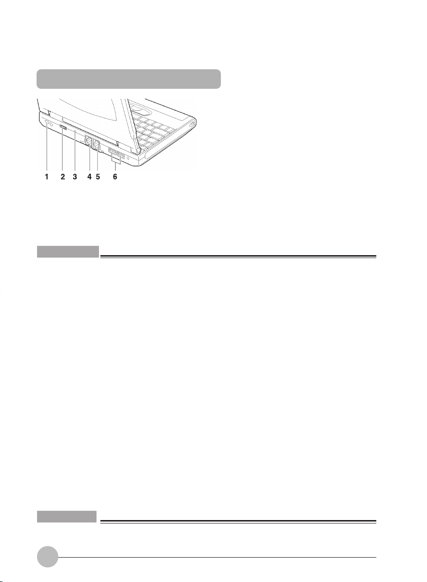
Rear features of the computer
(The illustration varies depending on the model and use conditions.)
1 Antitheft lock port
Used to connect a commercially available antitheft cable.
Critical Point
• The antitheft lock port supports the Kensington’s Micro Saver Security System.
2 External display connector
Used to connect an optional external display, such as a CRT display.
3 Shutdown switch
Used to shut down the computer forcibly. If this button is pressed while an application is running,
the data being processed may be lost.
4 Modem Port
This connector allows you to connect the computer to a telephone line and enables PC
communications and Internet connection through the supplied modular cable.
5 LAN port
Used to connect the computer to a local-area network (LAN) via an optional LAN cable so that
you can use your computer on a network or connect to the Internet.
6 USB port
You can connect separately available USB standard peripherals such as a FDD unit or printer to
this port.
IMPORTANT
• When you connect peripheral devices to each corresponding connector, confirm the correct
direction of the connector and insert directly into the connector.
6
Page 20
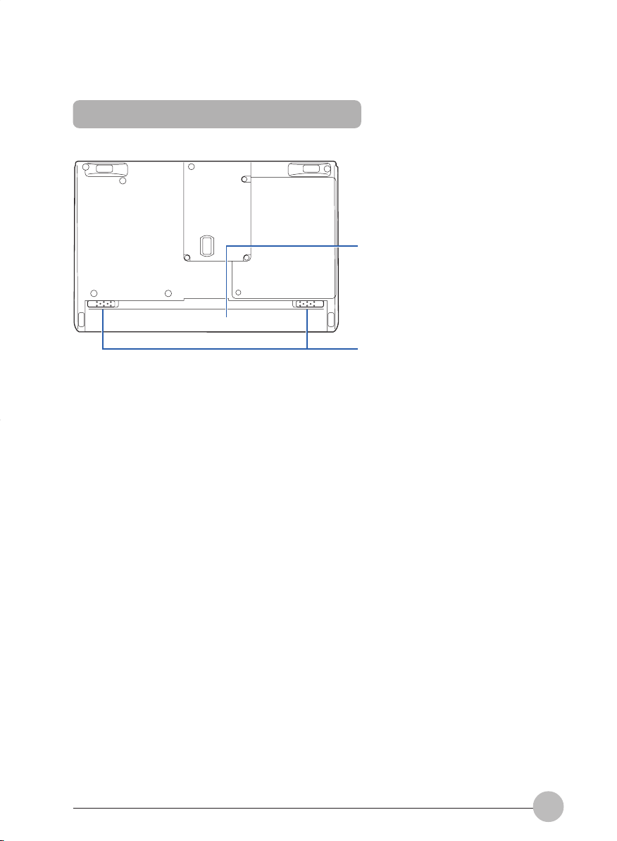
Bottom features of the computer
1 Battery pack
An internal battery pack is installed here.
2 Battery pack lock
Slide this to remove the battery pack.
1
2
7
Page 21
SECTION 1
2. Status Indicator LCD
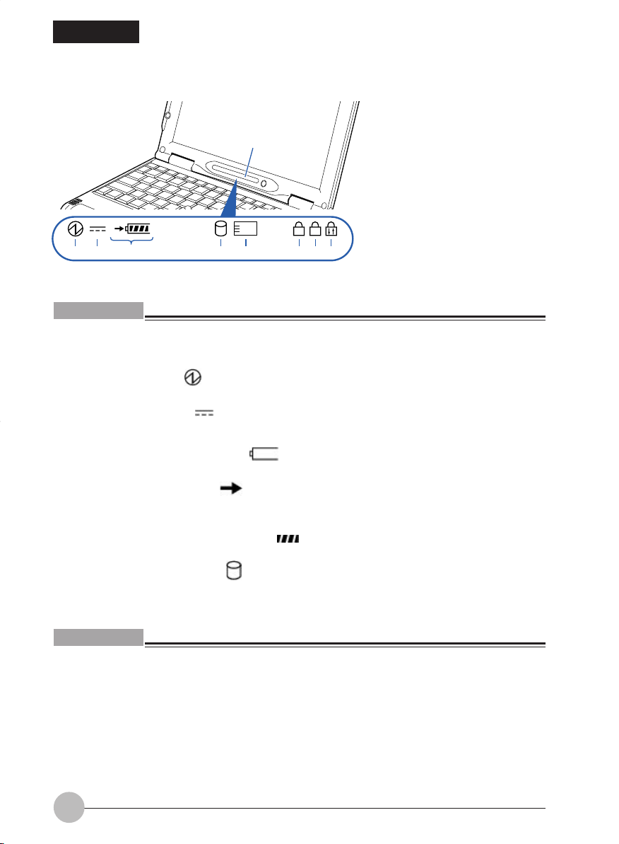
Status indicator LCD
1
1123 4 6785
A1
Critical Point
• No indicator is displayed on the status indicator LCD when your computer is turned off, except
when the computer is being recharged.
1 SUS/RES indicator ( )
This indicator comes on when the computer is running and blinks in standby status.
2 AC adapter indicator ( )
This indicator comes on when the power is supplied from the AC adapter.
3 • Battery installation indicator (1 )
This indicator appears when the battery is installed.
• Battery charge indicator ( )
This indicator appears when the battery is charged and blinks when battery charge is not
in progress because the battery is too hot or too cold.
• Remaining battery power indicator ( )
This indicator indicates the remaining battery power.
4 Hard disk access indicator ( )
This indicator appears when the internal hard disk is accessed.
Critical Point
• If you operate the Shutdown or SUS/RES switch while the hard disk access indicator is sho wing,
the data on the hard disk may be corrupted.
8
Page 22
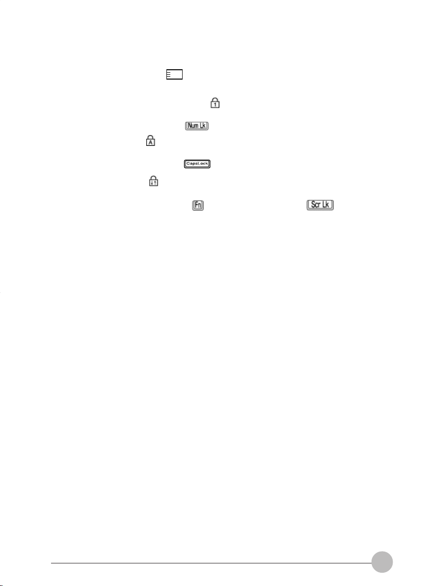
5 PC Card access indicator ( 1 )
This indicator appears when a PC card is accessed.
6 Num Lock (Numerical Lock) indicator ( )
This indicator appears when the keyboard is set to ten-key mode. You can activate and deactivate
the ten-key mode by pressing the [ ] key.
7 Caps Lock indicator ( )
This indicator appears when the keyboard is set for all capital letters. You can activate or deactivate
the Caps Lock mode by pressing [ ] key.
8 Scroll Lock indicator ( )
This indicator appears when the scroll lock is activated to avoid screen scrolling. You can set and
reset the scroll lock by pressing the [ ] key while holding down the [ ] key.
The operation varies depending on the application when this indicator appears.
9
Page 23
SECTION 1
3. Using Quick Point IV
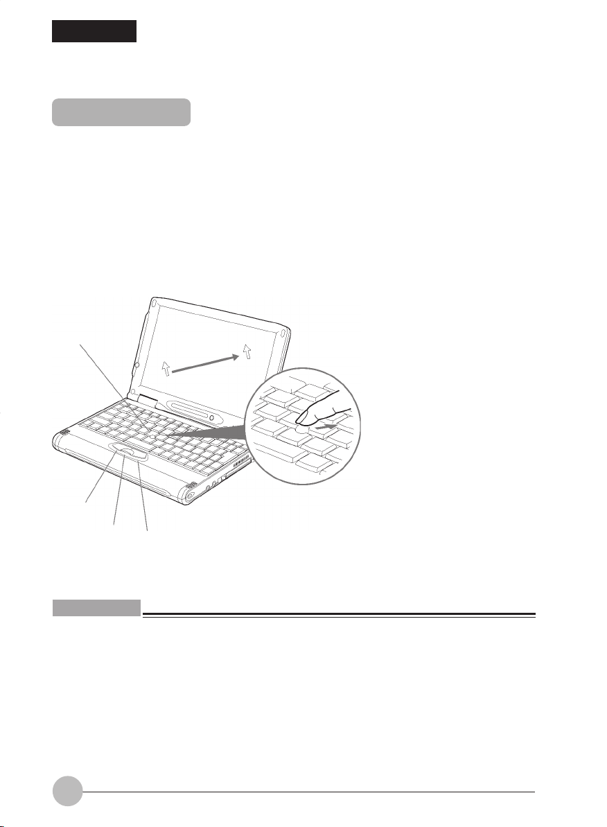
Quick Point IV
Quick Point IV is a convenient pointing device, which enables you to control the mouse pointer with
your fingertip. It is composed of a stick located at the center, and buttons located at the front of the
keyboard.
The stick functions as a ball inside a mouse and moves the mouse pointer around the screen - up,
down, left and right as you press it lightly with your finger tip.
The left button works as the left mouse button and the right button as the right mouse button. The
functions they perform vary depending on the application you are running.
The scroll button between the left and right buttons is used to scroll the screen.
Stick
Left button
Scroll button
Right button
Critical Point
• You can use a separately available USB mouse.
• The surface of the stick cap will become slippery after long use. Replace the old cap with a new
rubber cap supplied with the computer.
• Some applications do not allow you to use the scroll button to scroll windows.
10
Page 24

How to use Quick Point IV
Put your finger tip on the stick and press it up, down, left or right and the mouse pointer will move
accordingly. Try to press the stick while confirming the mouse pointer movements on the screen.
The mouse pointer may sometimes move spontaneously, but this does not indicate that Quick Point
IV is defective. If this phenomenon arises, wait (for about 3 seconds) until the mouse pointer comes
to a full stop before starting operation.
How to press buttons
• Clicking
Clicking means pressing the left button once and releasing it
immediately. Pushing the right button once is called “right clicking.”
• Double-clicking
Double-clicking means pressing the left button twice in rapid
succession and releasing it immediately.
• Pointing
Pointing means moving the mouse pointer onto a menu item, and so
on, to select it. Pointing to an item highlights it and displays an
explanation about it. If the item to which you pointed has a submenu
(such items are marked with ), the submenu appears.
• Dragging
• Scrolling
Dragging means moving the mouse pointer onto an object, keeping
the left button depressed while moving the mouse pointer by pressing
the stick to the desired location, and then releasing the button.
To scroll the screen, click on the area within the window, then move
the stick while keeping the scroll button depressed. The stick
movements upward, downward, to right and left allow you to scroll
the screen in the corresponding directions.
11
Page 25
Critical Point
• You can change the functions assigned to the right and left buttons and also adjust the mouse
speed, using the Mouse Properties dialog box. To display this dialog box, click the Printers and
other hardware icon in the Control Panel window and select Mouse.
• The mouse pointer may sometimes move in the reverse direction when you move it slowly for
several seconds by slightly tilting the Quick Point IV stick, but this does not indicate that Quick
Point IV is defective. Wait for a while until the mouse pointer comes to a full stop.
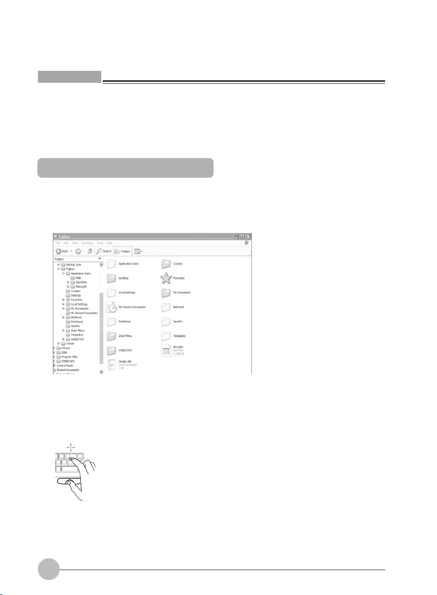
Using the scrolling function
The scroll button enables you to easily scroll a window up, down, to the right, or to the left.
1 Click anyplace in the area (of the window) that you want to scroll.
(The illustration varies depending on the model and use conditions.)
2 Move the stick in the direction in which you want to scroll the window while holding down
the scroll button.
The area you selected in the window will scroll in the same direction you moves the stick.
12
Page 26

SECTION 1
4. Replacing the Internal Battery Pack
• Before replacing the battery pack, be sure to turn off the computer
and disconnect the AC adapter from it. Also, don’t touch any connector
of the computer or battery pack to avoid electric shock or malfunction.
Preparing necessary items
The following battery packs are available for your computer.
Internal battery pack
Internal battery pack (L)
Your computer came with this battery pack.
This battery pack has a larger capacity than the above battery
pack, so it is useful for using the computer without connecting
the AC adapter for a long time.
For more information, contact your Fujitsu reseller.
Replacing the internal battery pack
1 Turn off the power to the computer and disconnect the AC adapter.
2 Place the computer, as shown below.
13
Page 27
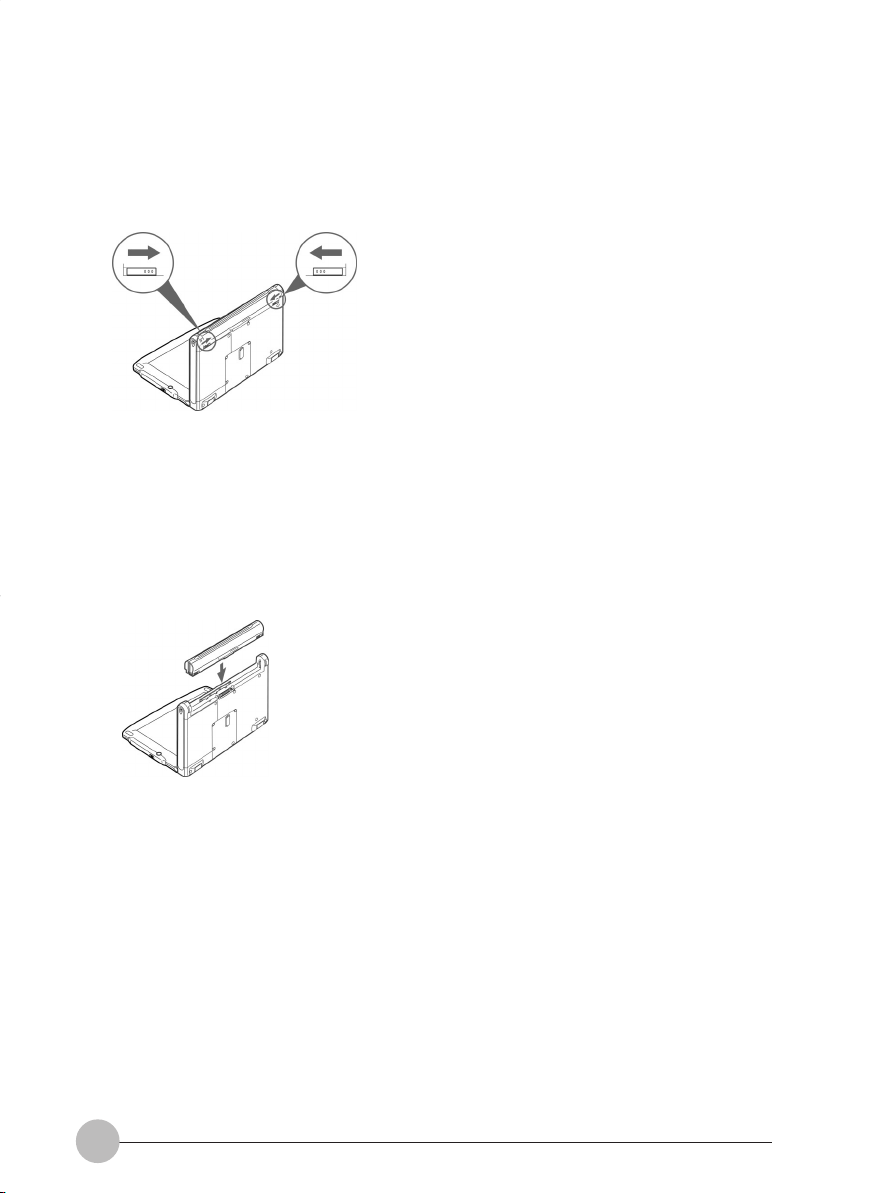
3 Remove the battery pack.
Remove the battery pack, sliding both of the battery pack locks to unlock it.
(The following illustrations vary depending on
the model and use conditions.)
4 Install a new battery pack.
Insert the new battery pack horizontally into the computer and push it firmly until it clicks. The
battery pack is automatically locked.
14
Page 28

SECTION 1
5. E-mail Button
A unique feature of your Fujitsu LifeBook is the E-mail Launcher Button. This button allows you to
launch the E-mail application with the touch of the button.
By using the E-mail button in conjunction with your E-mail button setup , y ou can connect to your ISP,
check for and retriev e new mail, terminate connection and launch you E-mail application to notify that
new E-mail has arrived in your mailbox.
In case you use more than one Internet Service Provider, only the specified Internet Service Provider
in the E-mail application could be used.
1 Configure your E-mail Launcher Button Application
When you start Windows XP, the Fujitsu Quick Touch application is automatically activated. An
icon resembling a finger pressing a button will appear on the system tray (the indented portion of
the status bar where the clock is displayed). When you see this icon you will know that Fujitsu
Quick Touch application is active. As an E-mail application launcher button, the Fujitsu Quick
Touch applcation is very flexible, giving you an options to set for using other E-mail application.
The default setting for the E-mail application is Outlook Express. We have provided the Fujitsu
Quick Touch application that quickly and easily helps you make the most of this v aluable f eature.
In order to reconfigure it to launch another E-mail application program follow these easy steps:
1 Click on Start
2 Click on All Programs
3 Click on Fujitsu Quick Touch
4 Click on Easy button
5 Easy button configuration menu will display on the screen
6 From the Easy button configuration menu, you will see the default setting for the E-mail
application is set to Outlook Express.
7 If you wish to change the E-mail application, you can click on the Browse or Browse from
start menu and select your E-mail application you wish to launch with this button.
8 Click OK and the button will now launch the new E-mail application.
15
Page 29

2 Configure the E-mail button.
For using the E-mail button, you must have access to a POP3 Server. Contact your service
provider to determine if they support POP3. To configure the E-mail button please follow these
easy steps:
1 Click on Start.
2 Click on All Programs
3 Click on Fujitsu Quick Touch
4 Click on Postman
5 The Postman setting screen will appear.
6 Choose the type of connection: LAN or Dialup.
If LAN : Click on LAN. Enter the POP3 Server name, your account name and password
If Dial Up : Click on Dial Up. Choose the Dial up configuration (as previously set in Dial Up
7 After all the information has been entered, test the connection by clicking on “T esting connection
with current setting”. If an error occurs , check the settings and information on Dial Up Network
and Postman setting. If no error found, it will show connection successful.
for that account. Consult your Service provider if you do not know or unsure of
the information requested.
Networking) you wish to retrieve mail from. Enter the POP3 Ser ver name, your
account name and password for that account.
When you have finished with E-mail b utton setup, y ou are ready to retriev e mail. When you press the
E-mail button, your system will establish connection with your provider, check for and retrieve new
mails, terminate the connection, and launch the mail application.
16
Page 30

SECTION 1
6. About the Internal Modem
Your computer has a V.90-compliant built-in fax modem.
• Do not insert your fingers into a modular jack, or you may receive an
electric shock.
• When using a modular cable, always connect it to a modular connector ,
otherwise your computer could break down.
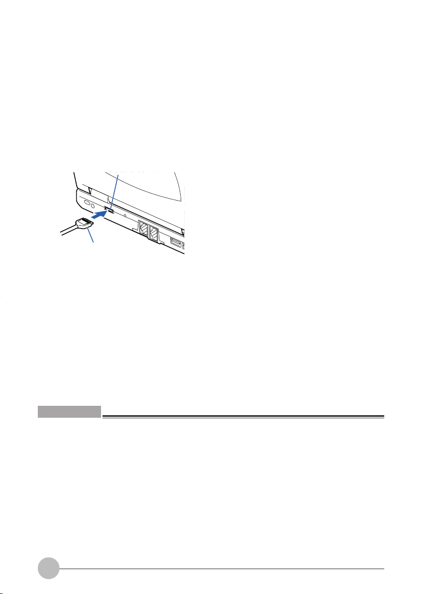
Connecting a modular cable
1 Insert the supplied modular cable into the rear panel of the computer.
Insert firmly until it clicks.
Modular connector
(The following illustrations vary depending
on the model and use conditions.)
2 Disconnect your telephone’s modular cable from the modular jack of the telephone line.
Pull it out while
pressing in the clip of
the modular cable.
17
Page 31

IMPORTANT
• If your telephone line connector is rosette type, it must be changed to a modular type.
If such a change is necessary, have it done by an authorized person.
You can also ask your telephone company to do the work.
Modular type
3 Connect the modular cable to the modular jack of the telephone line.
Insert the plug on the other end of the cable you have connected to the computer in Step 1.
Rosette type
Critical Point
• The telephone is not usable with its modular cable disconnected. Do not forget to connect it for
telephone use after finishing Internet communication.
• A modular cable may not be connected to your computer if it is routed around a household
electrical appliance, or wound and tied in an bundle.
• If the supplied modular cable is too short to connect your computer to a modular jack for the
telephone line, purchase a commercially availab le modular cable with a proper length. Note that
the use of a long modular cable may result in a transmission failure or a reduction in the
transmission rate.
• Do not connect a modular cable to the LAN port, otherwise your computer could break down.
Caution in using the internal modem
Connecting to the Internet for a long time while still running some applications applies a considerable
load on the CPU of the computer. It may lead to interruption of communication via the internal modem.
In this case, exit all applications you are running except your browser and e-mail software before
accessing the Internet again.
18
Page 32
Charging
1 Connect the AC adapter.
With the connection of the AC adapter, charging starts. The battery charge indicator ( ) and
the remaining battery power indicator appear on the status indicator LCD.
2 Make sure that the battery charge indicator disappears and disconnect the AC adapter.
Critical Point
• Charge the battery when you start using this computer after purchase or if you have not charged
it for more than 1 month.
• Batter y charging is complete when the battery charge indicator disappears and the leftmost
remaining battery power indicator changes from a blinking ( ) to a lit ( ). T ake sufficient
time for battery recharging to make sure that the battery is fully charged.
• When the remaining battery power is still 90% or more, the unit does not start charging even if
the AC adapter is connected. Charging starts when the power is 89% or less.
• When the computer is tur ned off, the indication on the status indicator LCD disappears soon
after charging is complete.
• The battery charging capability deteriorates if the room temperature is too high or too low.
• Battery charging might not begin if the battery temperature is too high after usage (the battery
charge indicator blinks in this case). Charging starts when the battery temperature falls after a
while.
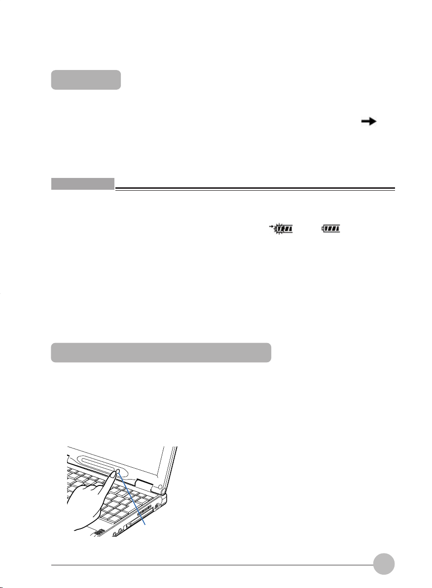
Using the computer with the battery
Here is the explanation of how to use the computer with the battery.
1 Remove the AC adapter and press the SUS/RES switch.
After the battery fully charge, remove the AC adapter and pow er on y our system using the SUS/
RES button or the On/Off switch. Now your system operate in Battery mode.
SUS/RES switch
19
Page 33

Critical Point
• When the room temperature is low, the battery operation time becomes shorter.
• When the battery has been used for a longer period, the battery operation time duration becomes
shorter because of the charging capability deterioration. If you notice that the operation time
length becomes extremely short, replace the battery with a new one.
Checking the remaining battery power
You can check the remaining battery power by looking at the remaining battery power indicator on
the status indicator LCD when the power is on or during charging.
Remaining battery power indicator
This means that the remaining battery power is between about 76% and 100%.
This means that the remaining battery power is between about 51% and 75%.
This means that the remaining battery power is between about 26% and 50%
This means that the remaining battery power is between about 13% and 25% (This represents 0% to
about 25% of remaining battery power during charging).
This indicates a low battery status (the remaining battery power is about 12% or less).
If the battery is weak
This means that the battery is completely exhausted (The remaining battery power is 0%).
blinks.
Critical Point
• The remaining battery power indicator may show a different indicator value from the actual
remaining battery power depending on the environment of use (temperature, battery usage and
recharging cycle numbers, etc.) because of the characteristics of the lithium ion battery.
• Charging does not start even if the AC adapter is attached when the remaining battery power is
90% or more. Charging starts when the power is 89% or less.
20
Page 34

Battery malfunction indicator
This means that the battery is not charged properly.
Critical Point
• When appears, turn off the power to the computer and reinstall the battery . If the indication
persists, the battery is defective. Replace it with a new battery.
Replacing the internal battery pack
If the battery is weak
When the battery power is beginning to run down, the remaining battery power indicator on the
status indicator LCD blinks ( ). In this case, connect the AC adapter and recharge the battery.
Critical Point
• If you continue to operate the computer when the battery is low , the data you are entering or in
the process of saving may be lost. Connect the AC adapter immediately or, if you do not have
one, quit the application you are running after saving the working data and then shut down the
power to the computer.
• Reading and writing processes on the hard disk consume a large amount of power. If you save
data on the hard disk when the battery is low, we recommend you to connect the AC adapter.
• If the computer is left in a low battery condition, it automatically goes into the standby mode. If
the system is reading/writing on the hard disk or other data storage media, howev er, it will wait
until the process is completed before entering the standby mode.
IMPORTANT
• This computer is preset to enter standby mode automatically when the remaining battery level
becomes low. Do not change the settings in the f ollowing items under P ower Options Properties.
Low battery alarm
– Activate low battery alarm when power level reaches 10 % is default setting. Under Alarm
Action you can set the setting of low battery alarm actions.
Critical battery alarm
– Activate critical battery alarm when power level reaches 3% is default setting. Under Alarm
Action you can set the setting of critical battery alarm actions.
If you use your computer with these items unchecked ( ), the power will be immediately shut
down when the battery becomes dead and unsaved data will be lost. It could also lead to a
system failure.
21
Page 35

Notes on the battery
• The battery is very sensitive. When you install or remove the battery,
be careful not to subject it to shocks by dropping it or otherwise. For
safety, do not use a battery that has been subjected to shocks, as it
may cause an electric shock or burst.
• Electric discharge
– The battery continues to discharge even if the computer is not used after charging, so we
recommend you charge the battery immediately before use.
– If you are not going to use the computer for a long time (more than one month), remov e the
battery and store it in a cool place. If the battery is left installed in the computer for a long
time, it will discharge excessively and the life of the battery will be shortened.
• Battery life
– The battery continues to age and deteriorate even if the computer is not in use for a long
time. Check the battery condition at least once a month by using the computer with the
battery power source.
– The battery is a consumable product and the battery’s charging capacity is reduced as the
battery ages.
– If your battery runs low quickly, it is a sign that it is getting old.
• Disposing of the battery
When you dispose of a battery, tak e measures so as to insulate the battery terminals with tape to
prevent short-circuiting. Also, check with your local government authority for details regarding
disposal of batteries.
• Prolonging actual battery life
Use the power saving function to prolong the actual battery life.
• Conditions where the actual battery life will be shortened
– The actual battery life varies depending on the temperature of use, and may be shortened in
a low temperature environment.
– The battery charging capacity is reduced as the battery ages. If your battery is running low
quickly, you should replace it with a new one.
• Use the AC adapter when;
– performing PC communication or Internet communication for a long time,
– using the hard disk and CD/DVDs frequently,
– using a LAN, or
– restoring the pre-installed software status of the computer when you purchased it.
• For PC communication or Internet communication
– PC communication and Internet communication consume a large amount of power. Carefully
check the remaining power of the battery.
22
Page 36
SECTION 1
7. Using a LAN
Your computer has a built-in LAN device, so that it can be connected to a 10BASE-T or 100BASE-TX
network.
Preparing necessary items
LAN cables
Network device
Manual for the network
device used
LAN cables are available in two types: straight type and cross
type. You need to use a cable that meets the data transfer rate of
the network. So refer to the manual for the network device to
which you intend to connect your computer and prepare an
adequate cable.
Prepare a device that meets the objective of network
connection. Here are some examples of network devices.
• Network Cable
• Network Card
• Hub
Ways of connection and setting procedures vary depending on
the network device used. So be sure to read also the manual for
the network device used.
23
Page 37

Connecting a LAN cable
• Before connecting a LAN cable, always turn off your computer and
disconnect the AC adapter, or you could get an electric shock.
• If it thunders, immediately turn off the computer and disconnect the
AC adapter and LAN cable from it. Lightning could cause damage to
the computer and cause a fire in the worst case.
• Don’t put any finger into the LAN port, or you could get an electric
shock.
• Be sure to plug a LAN cable correctly in the LAN port. F ailure to do so
could cause your computer to fail.
1 Turn off your computer and disconnect the AC adapter.
2 Plug a LAN cable in the LAN port on the back of the computer.
(The illustration varies depending on the
3 Plug the LAN cable in the network device.
Connect the other end of the LAN cable that you connected in step 2, to the LAN port of the
network device, then turn on the network device.
4 Connect the AC adapter to the computer and turn the power on.
5 Click the Start button and select Control Panel.
LAN port
model and use conditions.)
24
Page 38

6 Click Performance and Maintenance, then Power Option.
7 Click of “System standby” on the Power Schemes tab, and select “Never.”
8 Click of “System hibernates” and select “Never.”
9 Click OK.
10 Make all necessary network settings.
IMPORTANT
• When you are connecting to a local area network (or the Internet) using the LAN function, you
should not put your computer into Standby or Hibernation mode. Doing so could cause your
computer to break connection with the network (or the Internet), depending on the environment
in which your computer is being used.
Needless to say, however, you should turn off your computer whenever you will not use it for a
long period of time.
• Your computer is configured by default so that the LAN device will not operate if you turn on the
computer before connecting a LAN cable to it when the computer is powered by the internal
battery.
Critical Point
• Before disconnecting the cable from the LAN port, turn off the computer and unplug the AC
adapter from it, while pushing in the tab to avoid damage to the plug.
• When using the LAN device, you should preferably power your computer from the AC adapter
since the LAN device consumes a large amount of electrical power.
• The built-in LAN device in your computer cannot be used simultaneously with any LAN card.
• If the LAN device does not operate normally, make all necessary settings.
• To avoid damage to the LAN device, do not to connect a LAN cable to the modular connector.
25
Page 39
SECTION 1
8. Exterior Features
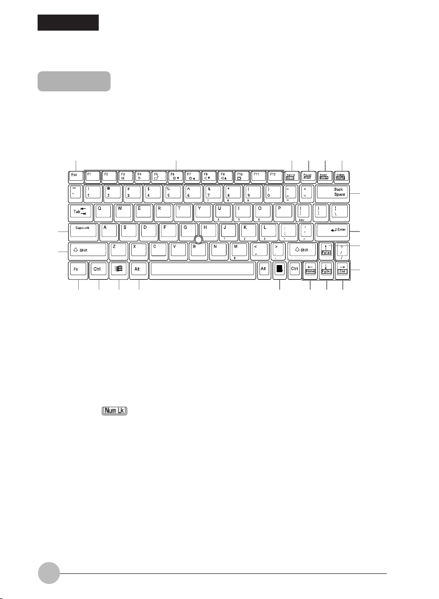
Keyboard
Names and functions of the principal keys
Keys that can be used as ten-keys.
1
2
6
5
4
3
9
7
8
14 15 18 19 20
13
1 Esc (Escape) key
Used to cancel the current task and return to the previous task.
2 Function keys
Functions assigned to these keys vary from application to application.
3 Num Lk (Numerical Lock) key
Pressing the [ ] key activates the ten-key mode. To deactivate the ten-key mode, press it
once again.
4 Pause/ Break key
• Pause key
Press this key to pause the scree display.
• Break
Its function depend on the application software.
16 17
10
11
12
26
Page 40
5 Insert / Prt Sc (Print Screen) key
• Insert key
Used to specify whether to overwrite an existing string or to insert a new string.
• Prt Sc (Print Screen) key
Used to save the currently displa yed windows as pictorial data (bitmap file). To do so, press
the [ ] key while holding the [ ] key down.
To save only the active window as pictorial data, press the [ ] key while holding the
[ ] and [ ] keys down.
Using painting software (e.g., Paint), y ou can edit, save , and print pictorial data. To do so, you
need to import it to the painting software by selecting the Paste command from the Edit
menu.
6 Delete / SysRq key
• Delete key
Used to delete the character on the right of the cursor. With this key, you can also delete the
file or icon you selected.
By pressing the [ ] key while holding the [ ] and [ ] keys do wn, you can forcibly
terminate the out-of-control application or computer.
• Sys Req key
When this key is supported by the application software, this ke y is used for such functions as
resseting the keyboard. Press this key tohether with the Fn key.
7 Caps Lock key
To type in all capital letters, press the [ ] key. To deactivate the capital mode, press these
keys again.
8 Shift key
Used in combination with other keys. By pressing a k e y while holding the [ ] ke y down, y ou
can enter the character or symbol printed in the upper case of the key.
9 Back Space key
Used to delete the character on the left of the cursor.
10 Enter key
Used to confirm the string entered.
In text processing, pressing this key inserts a hard return in the text. That’s why this key is also
called the Return key.
11 Pg Up (Page Up) key
Used to return to the previous page. To do so, press the [ ] key while holding the [ ] key
down.
12 Cursor keys
Used to move the cursor upward, downward, to right and left.
27
Page 41

13 FUNCTION KEYS
Your LifeBook has 12 function keys, F1 through F12. The functions assigned to these keys diff er
for each application. Y ou should ref er to y our softw are documentation to find out how these k eys
are used.
The [FN] key provides e xtended functions for the Lif eBook and is always used in conjunction with
another key.
• [FN+F3]: Pressing [F3] while holding [FN] will toggle the Audio Mute on and off.
• [FN+F4]: Pressing [F4] while holding [FN] will toggle the Quick Point IV feature on or off . When
the "Manual Setting" is selected under “Ke yboard/Mouse Features” - "Internal P ointing Device"
of the BIOS Setup Advanced Menu window.
• [FN+F5]: Pressing [F5] while holding [FN] allows you to toggle between video compensation
and no compensation.
• [FN+F6]: Pressing [F6] repeatedly while holding [FN] will lower the brightness of your display.*
• [FN+F7]: Pressing [F7] repeatedly while holding [FN] will increase the brightness of the display .*
• [FN+F8]: Pressing [F8] repeatedly while holding [FN] will decrease the volume of your LifeBook.**
• [FN+F9]: Pressing [F9] repeatedly while holding [FN] will increase the volume of your LifeBook.**
• [FN+F10]: Pressing [F10] while holding [FN] allows you to change your selection of where to
send your display video . Each time you press the combination of keys you will step to the next
choice. The choices, in order, are: built-in display panel only, both built-in display panel and
external monitor or external monitor only.
* There are eight brightness levels.
** There are 17 audio levels.
14 Ctrl key
Used in combination with other keys.
15 Windows key
Used to open the Start menu.
16 Alt key
Used in combination with other keys.
17 Application key
Used to open the pop-up menu for the item selected.
This key has the same function as the right button of Quick Point IV.
28
Page 42

18 Home key
Used to move the cursor to the beginning of the line on which it is currently placed. To do so,
press the [ ] key while holding the [ ] key down. Pressing the [ ] key while holding the
[ ] and [ ] keys down causes the cursor to move to the beginning of the text.
19 Pg Dn (Page Down) key
Used to display the next page. To do so, press the [ ] key while holding the [ ] key down.
20 End key
Used to move the cursor to the end of the line on which it is currently placed. To do so , press the
[ ] key while holding the [ ] key down. Pressing the [ ] key while holding the [ ] and
[ ] keys down causes the cursor to move to the end of the text.
About the ten-key mode
The ten-key mode refers to the mode that enables you to use certain character entry keys as tenkeys (a key arr angement that makes it easy to type in figures). To activate the ten-key mode, simply
press the [ ] key. In the ten-key mode, is displayed on the status indicator LCD. The figure
you can enter with a ten-key is marked on the front surface of the key.
29
Page 43

30
Page 44

SECTIONSECTION
SECTION
SECTIONSECTION
SECTIONSECTION
SECTION
SECTIONSECTION
22
2
22
22
2
22
This section explains installation
of options for this computer.
SECTION 2
Page 45

SECTION 2
1. Before Connecting Peripherals
Here is an explanation of the basic knowledge you need before connecting peripherals.
• Some changes to settings are required for certain peripherals.
You cannot use some peripherals just by connecting them to the computer. Such peripherals
require some changes to settings after connection. For example, printers and PC cards require
“driver installation” work after connecting them. Some peripherals do not require such setting
changes. Alw ays consult with this manual when connecting a peripheral to complete any settings
correctly.
If a floppy disk is required for the driver installation, prepare an optionally available FDD unit
(USB).
• Refer to the manual.
This manual explains how to connect peripherals as an e xample . When connecting a peripheral
device, always make reference to the manual for it besides this manual.
• Use genuine products
T o know about FUJITSU genuine optional de vices, consult with your dealer . We cannot guarantee
the proper function of this computer when using peripherals from other sources. If it becomes
necessary to use a peripheral from another source, consult with the manufacturer of that product.
• Use peripherals that conform to ACPI standards
This computer is set to ACPI mode. P o wer saving and other functions may not work correctly if a
peripheral does not work in ACPI mode.
Moreover, your computer does not support the Low-Level Standby (ACPI S1) feature.
If any peripheral device used supports only the Low-Level Standb y feature, don’t put y our computer
into standby or hibernation mode.
Critical Point
• When you connect a peripheral to a connector, mak e sure that the direction of the connection is
correct and connect straight.
• When connecting more than one peripheral, complete the setting for each one before installing
the next.
32
Page 46

SECTION 2
2. Connecting a Mouse
Connecting a USB mouse
1 Plug the mouse cable in the USB port on the rear panel of the computer.
Insert the connector with the marked-face up.
(The illustration varies depending
on the model and use conditions.)
USB port
Critical Point
• A mouse can be connected and disconnected even when the computer is on.
• Connecting a mouse does not automatically disable Quick Point IV. To disable Quick Point IV,
follow the steps described in the next section, “Disabling Quick Point IV.”
Disabling Quick Point IV
When a USB mouse is connected to your computer, not only the USB mouse b ut also Quick P oint IV
are enabled. To disable Quick Point IV, follow these steps.
1 Press the [ ] key while holding the [ ] key down.
Quick Point IV s witches betw een Enab led and Disab led each time you press the [ ] key while
holding the [ ] key down. When you activ ate or deactivate Quick P oint IV, the message “Internal
pointing device: Enab led” or “Internal pointing device: Disab led” appears on the screen, respectively .
IMPORTANT
• Don’t disable Quick Point IV before connecting a mouse to your computer.
Critical Point
• Even when you disable Quick Point IV by pressing the [ ] key while pressing down the [ ]
key, Quick Point IV is enabled after restarting or resuming operation of the computer. T o disab le
it, you need to press the [ ] key again while holding the [ ] key down.
• Quick Point IV can be turned on and off manually only when the “Internal pointing device” item is
set to “Manual” under “Keyboard/Mouse Settings “ in the BIOS Setup Advanced Menu. If the
Manual option is unselected, select it.
• If you set the “Internal pointing device” item of the “K eyboard/Mouse Settings” in the BIOS Setup
Advanced Menu to “Always disabled”, Quick Point IV is always disabled.
33
Page 47

SECTION 2
3. Connecting a USB Device
Preparing necessary items
USB device
USB cable
USB device driver
Manual for USB device
Refers to USB standard-compliant devices. Here are typical
examples of USB devices. Prepare a USB device that meets
your need.
• Digital camera
• CCD camera
• Mouse
• Printer
• Scanner
• Keyboard
• Speaker
Used to connect a USB device to the computer. Some USB
devices come with a USB cable.
For some USB devices, e.g., USB mice, the USB cable is an
integral part of them.
For more information, refer to the manual for the USB device
you want to connect.
Some USB devices come with a CD or floppy disk that contains
their respective drivers. Refer to the instruction manual for the
USB device and use one that is compatible with Windows
installed on your computer.
Ways of connection vary from USB device to USB device.
So be sure to read also the manual for the USB device used.
Critical Point
• Each USB port is capable of supplying up to 500mA to the USB device connected if the de vice
requires no power supply from any other source. For more information, refer to the instruction
manual for your USB device.
34
Page 48

Connecting a USB device
1 Connect a cable to the USB device you want to use.
2 Plug the other end of the cable in the USB port on the rear panel of your computer.
Insert the cable with the USB connector’s -marked surface facing upward.
(The illustration varies depending on the model
3 Install the device driver.
Some USB devices get ready for use only if being connected and they don’t require the installation
of a driver. For more information, refer to the manual for the USB device used.
A floppy disk or a CD may be required to install a driver.
USB port
and use conditions.)
Critical Point
• If the Install Hardware dialog box appears when you connect a USB cable, click Continue to
install the device driver.
35
Page 49
SECTION 2
4. PC Cards
Notes on using PC Cards
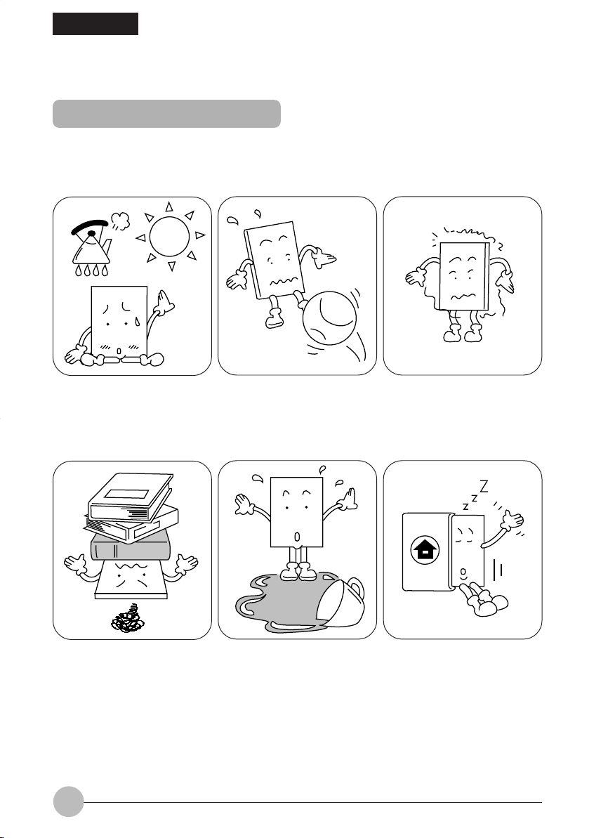
Observe the following points when using PC cards to prevent breakdown.
You should pay attention to the following points when you use PC Cards in order to prevent failures.
Do not place PC cards in hightemperature locations and
locations subject to direct
sunlight.
Do not place heavy objects on
top of PC cards.
Do not subject PC cards to
strong shocks.
Be careful to avoid spilling
coffee and other liquids on PC
cards.
Avoid rubbing PC cards and
building up static electricity.
When storing a PC card,
always place it in its special
case.
36
Page 50
Caution in using PC cards
• A PC card is composed of parts very sensitive to static electricity, and
it may be damaged even by static built up in a human body. Before
handling a PC card, always touch a metal object with your hand to
discharge static.
You should pay attention to the following points when you use PC cards in order to prevent failure.
PC cards that can be used with your computer
Y our computer is compatib le with PC Card Standard-compliant Type I PC cards and Type II PC cards.
Here are some examples of these types of cards.
• Adapter card
This PC card is needed to load pictorial data from a smart media for digital cameras into the
computer.
• SCSI Card
This PC card is needed to connect a SCSI device, such as a SCSI hard disk or MO (MagnetoOptical) drive.
• LAN card
This PC card is needed to connect your computer to other computers in order to share data or
a printer with them.
Critical Point
• Your computer does not support PC cards with a working voltage of 12V.
• No LAN card can be used simultaneously with the built-in LAN device.
Preparing necessary items
PC card
PC card driver
Manual of the PC card
Prepare a PC card that meets your need.
A CD or floppy disk that contains the PC card driver is supplied
with some PC cards.
Setting procedures vary depending on the PC card used. So be
sure to read also the manual of your PC card.
37
Page 51
Caution in using PC cards
• Do not put your finger into the PC card slot when you install a PC
card, or you may be injured.
Critical Point
• It may be required to turn off the power to the computer or to install a device driver when you
install a specific PC card. Check with the manual supplied with each PC card.
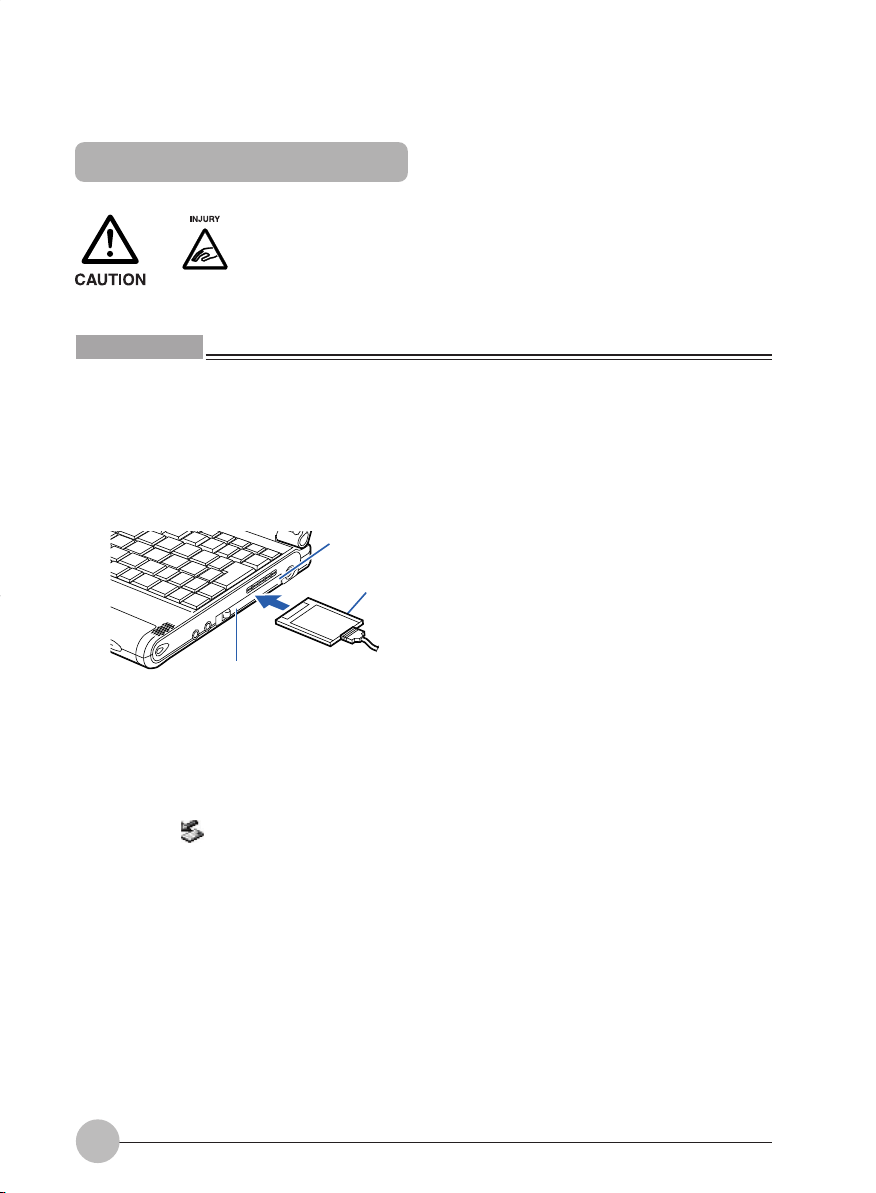
1 Install the PC card.
While pressing and holding down the PC card eject button, fully insert the PC card into the PC
card slot with the PC card product name facing upward.
PC card slot
PC card
PC card eject button
2 If the PC card is being installed for the first time, install any necessary driver.
Some PC cards require the installation of a driver. Chec k the manual supplied with each PC card
and install a driver if required.
A floppy disk or a CD may be required to install a driver.
3 Click the icon (Safety Remove Hardware) in the lower right corner of the screen
(notification area where a clock is displayed), and make sure that the name of the PC card
inserted is displayed correctly.
• If the name is displayed, the PC card is recognized correctly by the computer. Clic k a blank
space on the desktop.
• If no name is displayed, the PC card is not recognized correctly by the computer. Eject the
PC card, following steps 3 - 5 described in the “Ejecting a PC card” section, and install the
PC card again.
38
Page 52
Ejecting a PC card
Critical Point
• When you remove a PC card attached with a cable, do not pull the cable connected to the PC
card or it will result in failure.
• When you remove a PC card, follow the procedure below or it will result in failure.
• Some PC cards require shutting down when you remove them. Consult with the manual of the
PC card.
• A PC card may be quite hot right after use. Wait for a while before
removing a PC card after Step 3, to avoid burning your fingertips.
• When you remove a PC card, do not insert your finger into the PC
card slot to avoid cutting your fingertips.
1 Click the icon (Safety Remove Hardware) in the lower right corner of the screen
(notification area where a clock is displayed).
Critical Point
• Don’t eject the PC card by clicking the Stop button in the Safety Remove Hardware dialog box
that appears when you double-click the icon (Safety Remove Hardware) in the lower right
corner of the screen (notification area where a clock is displayed). Doing so may cause your
computer to become unstable.
2 Click “ XXXXXXXX can be removed safely.”
XXXXXXXX refers to the name of the PC card inserted.
Critical Point
• If the message, “The device “Gener al-Purpose Volume,” cannot be stopped now. Carry out the
steps later again to stop the device” appears , clic k OK, chec k to be sure that the PC card is not
being accessed, and then perform the above steps all over again, starting with step 1.
39
Page 53

3 When a message “Remove hardware” appears, press the PC card eject button.
The PC card eject button pops out.
PC card eject button
4 Eject the PC card.
Press the PC card eject button and pull out the PC card that has popped out.
PC card
PC card eject button
5 Push in the PC card eject button.
IMPORTANT
• Always push in the PC card eject button after ejecting a PC card. Using your computer with the
eject button jutting out could cause damage to the button.
40
Page 54
SECTION 2
5. Connecting an External Display
Preparing necessary items
External display
VGA Out connector
Display cable
Manual for the external
display used
Prepare an external display that supports PC/AT-compatible or
DOS/V computers.
Used to transform a display cable connector so that the display
can be connected to your computer.
This cable is bundle with the package.
Most external displays come with a display cable connected to
the back or a separate cable.
If no display cable is included with your external display or if the
VGA Out connector cannot be connected to your display cable,
prepare a display cable that is designed for PC/AT-compatible or
DOS/V computers and that has a connector compatible with the
VGA Out connector.
Ways of connection vary from display to display. So be sure to
read also the manual for the external display used.
Connecting an external display
This section explains how to connect a CRT display to the external display connector on the rear
panel of your computer.
• Before connecting or disconnecting an external display to your
computer, alwa ys turn off the computer and disconnect the AC adapter
from it. Failure to do so could lead to an electric shock.
• Before connecting a cable, read this man ual carefully so that you can
connect it correctly.
Connecting a cable incorrectly could cause your computer and external
display to break down.
41
Page 55
1 Turn off the computer and disconnect the AC adapter from it.
2 Connect a commercially available display cable to the VGA Out connector.
Engage the connectors securely with attention paid to their orientations.
3 Insert the VGA Out connector in the external display connector on the rear panel of the
computer.
Engage the connectors securely with attention paid to their orientations.
External display connector
VGA Out connector
(The illustration varies depending on
the model and use conditions.)
4 Plug the other connector of the VGA Out connector into the CRT display.
For the way to connect the cable, refer to the manual for your CRT display.
5 Plug the power cable of the CRT display in a wall outlet and turn it on.
6 Connect the AC adapter to the computer, turn it on, and then switch displays.
If the Add New Hardware Wizard dialog box appears after you hav e connected the external display,
perform the following.
• If your external display came with a CD or a floppy disk containing files, install all necessary
files, following the instructions of the manual for the external display.
Critical Point
• After an external display is connected to your computer, both the computer’s LCD and the e xternal
display may be activated simultaneously as the monitor of the computer.
• To disconnect the VGA Out connector from the computer, pull it while pushing down the button
on the top of the connector.
42
Page 56

SECTIONSECTION
SECTION
SECTIONSECTION
SECTIONSECTION
SECTION
SECTIONSECTION
33
3
33
33
3
33
This section explains what to do
when trouble occurs with this
computer and when messages
are displayed. Read this section
as the necessity arises.
SECTION 3
Page 57

SECTION 3
1. When This Happens
When you are having trouble with this computer, there is something you think is strange, or
there is something you want to do, but do not know how. This section is divided into related
items.
The power does not come on.
Checkpoint
Is the AC adaptor connected?
Is the main switch switched
on?
Is the battery charged?
Has the computer been left
unused for a long time?
Nothing displayed on the LCD panel
Checkpoint
Is anything displayed on the
status indicator LCD?
Is displayed on the LCD
panel?
When using this computer for the first time after purchase, the
battery is not yet charged, so you must connect the AC adaptor
and switch on the main switch.
If the main switch is not switched on, the power will not come on
even if the SUS/RES switch is pressed.
If a beep is heard when the main switch is turned on, then the
battery is running low (LOW BATTERY). Connect the AC
adaptor.
When using the computer for the first time after leaving it unused
for a long time, connect the AC adaptor and switch on the main
switch to switch on the power.
Connect the AC adaptor and switch on the main switch.
• Displayed
Adjust the brightness and darkness with the brightness and
contrast controls.
• Flashing
Press the SUS/RES switch to put the computer into operating
mode.
• When the icon is off on the status indicator LCD.
When the computer runs by the battery power, check the
battery status if it is sufficiently charged for operation or not.
If it is not charged, connect the AC adaptor and charge it.
If you are already using this computer with the AC adaptor
connected, check that it is correctly plugged into the power
socket and into the computer.
Cause and Solution
Cause and Solution
44
Page 58
Checkpoint
Have you been pressing any
of the keys?
Is it set to output to the CRT?
LCD panel hard to read.
Checkpoint
Did you adjust the
brightness?
Battery is not charged.
Checkpoint
Is the AC adaptor connected?
Is the battery overheated
(The on the LCD
display flashes.)?
Is the computer too cold
(The on the LCD
display flashes.)?
Was the charging stopped
midway?
Cause and Solution
On this computer, if the power management functions are set
and no key is pressed for a certain period of time, the CPU stops
and the LCD panel backlight goes out. (In this state, pressing
any key lights up the backlight again.) If the computer stops too
frequently, change the BIOS setup settings.
Switch over to the LCD display with the [Fn] + [F10] keys.
Cause and Solution
Adjust the luminance of the LCD’s backlight with the [Fn] + [F6]
keys or [Fn] + [F7] keys on the keyboard.
Cause and Solution
Check that the AC adaptor is correctly plugged into the power
socket and into the computer.
If the ambient temperature is high and the battery temperature
becomes too high during use, the battery protection function
may be triggered to stop the charging.
If the battery temperature falls too low, the battery protection
function may be triggered to stop the charging.
If you use the computer and disconnect the AC adaptor between
the start of charging and the time the LCD turns off, the
battery will not become fully charged, Once you start charging
do not remove the AC adapter until the LCD turns off.
The remaining battery charge indicator does not stop flashing.
Checkpoint
Is the battery connected
correctly?
Is the battery low?
Check that the battery is connected correctly. If it is connected
correctly, there is an abnormality in the battery pack, so replace
the battery pack.
Attach the AC adaptor and charge the battery.
Cause and Solution
45
Page 59

Floppy disk can not be used.
Checkpoint
Is the floppy disk loaded into
the floppy disk drive correctly?
Is the floppy disk formatted?
Is the floppy disk unit securely
installed?
Are both items of “Floppy disk
A” and “Floppy controller” of
the BIOS Setup menu set
properly?
Is “Administrator only”
selected for the item “Floppy
disk access” of the BIOS
Setup menu?
Is the floppy disk write
inhibited?
Does it work with a different
floppy disk?
No sound or minimal sound from speaker.
Checkpoint
Is the volume control correctly
adjusted?
Insert the floppy disk with its label facing up, into the drive
shutter and keep inserting firmly until you hear a clicking sound.
New floppy disks can not be used until they are formatted
(initialized). Format the floppy disk.
Firmly install the floppy disk drive unit to the system.
In the case a floppy disk is used, select “1.44/1.2MB 3.5” for the
item “Floppy disk A” and “Use” for the item “Floppy controller”.
In the case a floppy disk is used, select “Accessib le at any time”
for this item. When a super disk is used, accessibility cannot be
controlled by this item.
Set the write protect tab on the floppy disk to the write enable
position.
If it works with a different floppy disk then the problem floppy disk
may be damaged.
Turn the volume control to adjust the volume to a proper level. If
volume adjustment with the volume control results in failure,
check to see if the sound driver is correctly installed.
Cause and Solution
Cause and Solution
Can not record from Mic or Line In jack.
Checkpoint
Is the volume adjusted
properly?
LCD panel does not close.
Checkpoint
Is something caught in the
LCD panel?
Turn the volume control to obtain the correct volume. If the line
jack is connected to the sound source, then check that connection. If recording still results in failure after the above-mentioned
operation and check, activate the item “Recording” of the
“Volume Control” and again adjust the volume with it.
Forcing the LCD panel closed can damage it. Check for something caught in the LCD panel. Also, a metal object such as a
paper clip can cause a breakdown if it gets caught in between
the keys.
46
Cause and Solution
Cause and Solution
Page 60

The power management function is not executed.
Checkpoint
Is Power Savings set to off in
the BIOS setup?
Data cannot be read from the CD-ROM drive.
Checkpoint
Is the CD-ROM correctly set?
Is there any dirt, condensation
or water on the CD-ROM?
Is the CD-ROM scratched or
extremely warped?
Are you using a non-standard
CD-ROM?
Is the CD-ROM drive unit
securely installed?
The CD cannot be ejected from the CD-ROM.
Checkpoint
Is it in operating mode?
Reset the BIOS setup.
Set the CD-ROM correctly with its label facing upwards .
Wipe it from the center outwards with a dry, soft cloth.
Replace the CD-ROM.
Use a CD-ROM which conforms to the standards.
Securely install the CD-ROM drive unit.
The CD can only be ejected when the personal computer main
unit is in operating mode because its CD- ROM drive has an
electronic lock. Check that the personal computer main unit is in
operating mode and press the EJECT button. If for some reason
the CD tray does not come out even when you press the EJECT
button, insert a clip or something into the hole to the right of the
EJECT button and pull the tray out.
If the tray doesn’t still come out, click the CD-ROM icon in the
“My Computer” window with the right button of the mouse and
then click “EJECT”.
Cause and Solution
Cause and Solution
Cause and Solution
Super disk cannot be ejected.
Checkpoint
Is the computer in operation?
Cause and Solution
Since the super disk drive secures the super disk by the
electronic lock, the disk can be ejected only when the computer
is in the operation status.
If the super disk cannot be ejected for some reason, insert a thin
linear wire such as a straightened paper clip or the like into the
emergency disk ejecting hole and push it into the depth. The disk
will be resultingly ejected from the drive.
47
Page 61

SECTION 3
2. Care and Maintenance
If you use your Fujitsu LifeBook notebook carefully, you will increase its life and reliability . This section
provides some tips for looking after the notebook and its devices.
Caution:
Electrical equipment may be hazardous if misused. Operations of this product or similar products,
must always be supervised by an adult. Do not allow children access to the interior of any electrical
products and do not permit them to handle any cables.
LIFEBOOK NOTEBOOK
Caring for your LifeBook Notebook
• Your LifeBook notebook is a durable but sensitive electronic device. Treat it with care.
• Make a habit of transporting it in a suitable carrying case.
• Do not attempt to service the computer yourself. Always follow installation instructions closely.
• Keep it away from food and beverages.
• If you accidentally spill liquid on your notebook:
1. Turn it off.
2. Position it so that the liquid can run out.
3. Let it dry out for 24 hours, or longer if needed.
4. If your notebook will not boot after it has dried out, call your support representative.
• Do not use your LifeBook notebook in a wet environment (near a bathtub, swimming pool).
• Always use the AC adapter and batteries that are approved for your notebook.
• Avoid exposure to sand, dust and other environmental hazards.
• Do not expose your LifeBook notebook to direct sunlight for long periods of time as temperatures
above 140°F (60°C) may damage your notebook.
• Keep the covers closed on the connectors and slots when they are not in use.
• Do not put heavy or sharp objects on the computer.
• If you are carrying your LifeBook notebook in a briefcase, or any other carrying case, make sure
that there are no objects in the case pressing on the lid.
• Do not drop your LifeBook notebook.
• Do not touch the screen with any sharp objects.
Cleaning your LifeBook Notebook
• Always disconnect the power plug. (Pull the plug, not the cord.)
• Clean your LifeBook notebook with a damp, lint-free cloth. Do not use abrasives or solvents.
• Use a soft cloth to remove dust from the screen.Never use glass cleaners.
48
Page 62
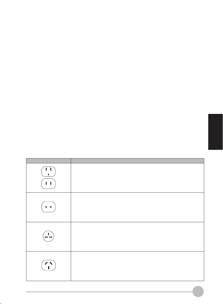
Storing your LifeBook Notebook
• If stor ing your notebook for a month or longer, turn your LifeBook notebook off and remove all
Lithium Ion batteries.
• Store your LifeBook notebook and batteries separately . If you store y our notebook with a battery
installed, the battery will discharge, and battery life will be reduced. In addition, a faulty battery
might damage your notebook.
• Store your LifeBook notebook in a cool, dry location. Temperatures should remain between 25°C (13°F) and 60°C (140°F).
Travelling with your LifeBook Notebook
• Do not transport your LifeBook notebook while it is turned on.
• Do not check your LifeBook notebook as baggage. Carry it with you.
• Always bring your System Recovery CD that came with your LifeBook notebook when you
travel. If you experience system software problems while travelling you may need it to correct
any problems.
• Never put your LifeBook notebook through a metal detector . Ha ve your notebook hand-inspected
by security personnel. You can, however, put your LifeBook notebook through a properly tuned
X-ray machine. To avoid problems, place your notebook close to the entrance of the machine
and remove it as soon as possible or hav e your notebook hand-inspected b y security personnel.
Security officials may require you to turn your notebook On. Make sure you have a charged
battery on hand.
SECTION 3
Outlet type
Location
United States, Canada, parts of Latin America, Japan, Korea, the
Philippines, T aiwan
Russia and the Commonwealth of Independent States (CIS), most of
Europe, parts of Latin America, the Middle East, parts of Africa, Hong
Kong, India, most of South Asia
Mexico, United Kingdom, Ireland, Malaysia, Singapore, parts of Africa
China, Australia, New Zealand
49
Page 63

• When travelling with the hard drive removed, wrap the drive in a non-conducting materials (cloth
or paper). If you have the drive checked by hand, be ready to install the drive if needed. Never
put your hard drive through a metal detector. Have your hard drive hand-inspected by security
personnel. You can however, put your hard drive through a properly tuned X-ray machine.
• Take the necessary plug adapters if you’re travelling overseas. Check the following diagram to
determine which plug adapter you’ll need or ask your travel agent.
BATTERIES
Caring for your Batteries
• Always handle batteries carefully.
• Do not short-circuit the battery terminals (that is, do not touch both terminals with a metal object).
Do not carry lose batteries in a pocket or purse where they may mix with coins, keys, or other
metal objects. Doing so may cause an explosion or fire.
• Do not drop, puncture, disassemble, mutilate or incinerate the battery.
• Recharge batteries only as described in this manual and only in ventilated areas.
• Do not leave batteries in hot locations for more than a day or two. Intense heat can shor ten
battery life.
• Do not leave a battery in storage for longer than 6 months without recharging it.
Increasing Battery Life
• Power your LifeBook notebook through the AC or optional auto/airline adapter whene ver possible.
• If your LifeBook notebook is running on battery power all day, connect it to the AC adapater
overnight to recharge the battery.
• Keep brightness to the lowest level comfortable.
• Set the power management for maximum battery life.
• Put your LifeBook notebook in Suspend mode when it is turned on and you are not actually
using it.
• Limit your DVD/CD-RW/CD-ROM access.
• Disable the Windows CD automatic insertion function.
• Always use fully charged batteries.
• Eject PCMCIA cards when not in use.
FLOPPY DISKS AND DRIVES
Caring for your Floppy Disks
• Avoid using the floppy disks in damp and dusty locations.
• Never store a floppy disk near a magnet or magnetic field.
• Do not use a pencil or an eraser on a disk or disk label.
• Avoid storing the floppy disks in extremely hot or cold locations, or in locations subject to se vere
temperature changes. Store at temperatures between 50°F (10°C) and 125°F (52°C)
• Do not touch the exposed part of the disk behind the metal shutter.
50
Page 64

Caring for your Floppy Disk Drive
• To clean, wipe the flopp y disk drive clean with a dry soft cloth, or with a soft cloth dampened with
water or a solution of neutral detergent. Never use benzene , paint thinner or other volatile material.
• Avoid storing the floppy disk drive in extremely hot or cold locations, or in locations subject to
severe temperature changes. Store at temperatures between 50°F (10°C) and 125°F (52°C)
• Keep the floppy disk drive out of direct sunlight and away from hating equipment.
• Avoid storing the floppy disk drive in locations subject to shock and vibration.
• Never use the floppy disk drive with any liquid, metal, or other foreign matter inside the floppy
disk drive or disk.
• Never disassemble or dismantle your floppy disk drive.
DVD/CD-RW/CDs
Caring for your DVD/CD-RW/CDs
• DVD/CD-RW/CDs are precision devices and will function reliably if given reasonable care.
• Always store your DVD/CD-RW/CDs in its case when it is not in use.
• Always handle DVD/CD-RW/CDs by the edges and avoid touching the surface.
• Avoid storing any DVD/CD-RW/CDs in extreme temperatures.
• Do not bend DVD/CD-RW/CDs or set heavy objects on them.
• Do not spill liquids on DVD/CD-RW/CDs.
• Do not scratch DVD/CD-RW/CDs.
• Do not put a label on DVD/CD-RW/CDs.
• Do not get dust on DVD/CD-RW/CDs.
• Never write on the label surface with a ballpoint pen or pencil. Always use a felt pen.
• If a DVD/CD-RW/CD is subjected to a sudden change in temperature, cold to warm condensation
may form on the surface. Wipe the moisture off with a clean, soft, lint free cloth and let it dry at
room temperature, DO NOT use a hair dryer or heater to dry DVD/CD-RW/CDs.
• If a DVD/CD-RW/CD is dirty , use only a D VD/CD-RW/CD cleaner or wipe it with a clean, soft, lint
free cloth starting from the inner edge and wiping to the outer edge.
SECTION 3
51
Page 65

Caring for your DVD/CD-RW/CD-ROM Drive
Your DVD/CD-RW/CD-ROM drive is durable but you must treat it with care. Please pay attention to
the following points:
• The drive rotates the compact disk at a very high speed. Do not carry it around or subject it to
shock or vibration with the power on.
• Avoid using or storing the drive where it will be exposed to extreme temperatures.
• Avoid using or storing the drive where it is damp or dusty.
• Avoid using or storing the drive near magnets or devices that generate strong magnetic fields.
• Avoid using or storing the drive where it will be subjected to shock or vibration.
• Do not disassemble or dismantle the DVD/CD-RW/D-ROM drive.
PC CARDS
Caring for your PC Cards
PC Cards are durable, but y ou must treat them with care. The documentation supplied with your PC
Card will provide specific information, but you should pay attention to the following points:
• To keep out dust and dirt, store PC Cards in their protective slee v es when the y are not installed
in your notebook.
• Avoid prolonged exposure to direct sunlight or excessive heat.
• Keep the cards dry.
• Do not flex or bend the cards, and do not place heavy objects on top of them.
• Do not force cards into the slot.
• Avoid dropping cards, or subjecting them to excessive vibration.
52
Page 66

SECTION 3
3. Glossary
AC Adapter
A device which converts the AC voltage from a wall outlet to the DC voltage needed to power your
notebook.
Active-Matrix Display
A type of technology for making flat-panel displays which has a transistor or similar device for every
pixel on the screen.
APM
Advanced Power Management.
Auto/Airline Adapter
A device which converts the DC voltage from an automobile cigarette lighter or aircraft DC power
outlet to the DC voltage needed to power your notebook.
BIOS
Basic Input-Output System. A program and set of default parameters stored in ROM which tests and
operates your notebook when you turn it on until it loads your installed operating system from disk.
Information from the BIOS is transferred to the installed operating system to provide it with information
on the configuration and status of the hardware.
Bit
An abbreviation for binary digit. A single piece of information which is either a one (1) or a zero (0).
bps
An abbreviation for bits per second. Used to describe data transfer rates.
Boot
To start-up a computer and load its operating system from disk, ROM or other storage media into RAM.
Bus
An electrical circuit which passes data between the CPU and the sub-assemblies inside your notebook.
Byte
8 bits of parallel binary information.
Cache Memory
A block of memory built into the micro-processor which ins much faster to access than your system
RAM and used in specially structured ways to make your overall data handling tine faster.
CardBus
A faster, 32-bit version of the PC Card interface which offers performance similar to the 32-bit PCI
architecture.
CD-ROM
Compact disc read only memory. This is a form of digital data storage which is read optically with a
laser rather than a magnetic head. A typical CD-ROM can contain about 600MB of data and is not
subject to be crashing into the surface and destroying the data when there is a failure nor to wear
from reading.
SECTION 3
53
Page 67

CMOS RAM
Complementary metal oxide semiconductor random access memory . This is a technology for
manufacturing random access memory which requies very low level power to operate.
COMM Port
Abbreviation for communication port. This is your serial interface connection.
Command
An instruction which you give your operating system. Example: run a particular application or format
a floppy disk.
Configuration
The combination of hardware and software that make up your system and ho w it is allocated for use .
CRT
Cathode Ray Tube. A display de vice which uses a beam of electronic particles striking a luminescent
screen. It produces a visual image by varying the position and intensity of the beam.
Data
The information a system stores and processes.
DC
Direct current. A voltage or current that does not fluctuate periodically with time.
Default Value
A pre programmed value to be used if you fail to set your own.
DIMM
Dual-in-line memory module.
LAN
Local Area Network. An interconnection of computers and peripherals within a single limited geogr aphic
location which can pass programs and data amongst themselves.
LCD
Liquid Crystal Display . A type of displa y which makes images by controlling the orientation of crystals
in a crystalline liquid.
Lithium ion Battery
A type of rechargeable battery which has a high power-time life for its size and is not subject to the
memory effect as Nickel Cadmium batteries.
LPT Port
Line Printer Port. A way of referring to parallel interface ports because historically line printers were
the first and latter the most common device connected to parallel ports.
MB
Megabyte.
54
Page 68

Megahertz
1,000,000 cycles per second.
Memory
A repository for data and applications which is readily accessible to your notebook CPU.
MHz
Megahertz.
MIDI
Musical Instrument Digital Interface. A standard communication protocol f or e xchange of information
between computers and sound producers such as synthesizers.
Modem
A contraction for MOdulator-DEModulator. The equipment which connects a computer or other data
terminal to a communication line.
Monaural
A system using one channel to process sound form all sources.
MPU-401
A standard for MIDI interfaces and connectors.
NTSC
National TV Standards Commission. The standard for TV broadcast and reception for the USA.
Operating System
A group of control programs that convert application commands, including driver programs, into the
exact form required by a specific brand and model of microprocessor in order to produce the desired
results from that particular equipment.
Parallel Port
A connection to another device through which data is transferred as a block of bits simultaneously
with a wire for each bit in the block and with other wires only for control of the device not f or tr ansfer
of data.
Partition
A block of space on a hard drive which is set aside and made to appear to the operating system as if
it were a separate disk, and addressed by the operating system accordingly.
PCMCIA
PCMCIA is trademark of the Personal Computer Memory Card International Association. The P ersonal
Computer Memory Card International Association is an organization that sets standards for add-in
cards for personal computers.
Peripheral Device
A piece or equipment which performs a specific function associated with but not integral to a computer .
Examples: a printer, a mode, a CD-ROM.
SECTION 3
55
Page 69

Pitch (keyboard)
The distance between the centers of the letter keys of a keyboard.
Pixel
The smallest element of a display, a dot of color on your display screen. The more pix els screen. The
more pixels per area the clearer your image will appear.
POST
Power On Self Test. A prog ram which part of the BIOS which checks the configuration and operating
condition of your hardware whenev er power is applied to y our notebook. Status and error messages
may be displayed before the operating system is loaded. If the self test detects failures that are so
serious that operation can not continue, the operating system will not be loaded.
Disk
A spinning platter of magnetic data storage media. If the platter is very stiff it is a hard drive, if it is
highly flexible it is a floppy disk, if it is a floppy disk in a hard housing with a shutter it is commonly
called diskette.
Disk Drive
The hardware which spins the disk and has the heads and control circuitry for reading and writing the
data on the disk.
Diskette
A floppy disk in a hard housing with a shutter.
DMA
Direct Memory Access. Special circuitry for memory to memory transfer of data which do not require
CPU action.
DMI
Desktop Management Interface. A standard that provides PC management applications with a common
method of locally or remotely querying and configuring PC computer systems hardware and software
components, and peripherals.
DOS
Disk Operating System (MS-DOS is a Microsoft Disk Operating System).
Driver
A computer program which converts application and operating system commands to external de vices
into the exact from required by a specific brand and model of de vice in order to produce the desired
results from that particular equipment.
ECP
Extended Capability Port. A set of standards f or high speed data communication and interconnection
between electronic devices.
56
Page 70

ESD
Electro-Static Discharge. The sudden discharge of electricity form a static charge which has built-up
slowly . Example: the shock y ou get from a doorknob on a dry day or the sparks you get form brushing
hair on a dry day.
Extended Memory
All memory more than the 640KB recognized by MS-DOS as system memory.
FCC
Federal Communication Commission.
Floppy Disk
A spinning platter of magnetic data storage media which is highly flexible.
GB
Gigabyte.
Hard drive
A spinning platter of magnetic data storage media where the platter is very stiff.
Hexadecimal
A decimal notation for the value of a 4 bit binary number. (0-9, A, B, C, D, E, F) Example: 2F in
hexadecimal = 00101111 = 47 in decimal.
I/O
Input/Output. Data entering and leaving your notebook in electronic form.
I/O Port
The connector and associated control circuits for data entering and leaving your notebook in electronic
form.
IDE
Intelligent Drive Electronics. A type of control interf ace for a hard drive which is inside the hard drive
unit.
Infrared
Light just beyond the red portion of the visible light spectrum which is invisible to humans.
IR
An abbreviation for infrared.
IrDA
Infrared Data Association. An organization which produces standards f or communication using infrared
as the carrier.
IRQ
Interrupt Request. An acronym f or the hardware signal to the CPU that an external ev ent has occurred
which needs to be processed.
SECTION 3
57
Page 71

KB
Kilobyte.
Program
An integrated set of coded commands to your computers telling your hardware what to do and how
and when to do it.
PS/2
An IBM series of personal computers which established a number of standards for connecting external
devices such as keyboards and monitors.
RAM
Random Access Memory. A hardware component of your notebook that holds binary information
(both program and data) as long as it has the proper power applied to it.
RAM Module
A printed circuit card with memory and associated circuitry which allows the user to add additional
memory to the computer without special tools.
Reset
The act of reloading the operating system. A reset erases all information stored in RAM.
Restart
See Reset.
Resume
T o proceed after interruption. In y our notebook this refers to returning to active oper ation after having
been in one of the suspension states.
ROM
Read Only Memory. A f orm of memory in which information is stored by physically altering the material.
Data stored in this way can not be changed by y our notebook and does not require power to maintain
it.
SDRAM
Synchronous Dynamic Random Access Memory.
Serial Port
A connection to another device through which data is transferred one bit at a time on a single wire
with any other wires only for control of the device not for transfer of data.
Shadow RAM
A technique of copying data or applications stored in ROM (Read Only Memory) into RAM (Random
Access Memory) for access during actual operation. RAM is much f aster to access than ROM, howe ver
ROM contents are not lost when power is removed. Shado wing allows permanently stored information
to be rapidly accessed.
58
Page 72

SMART
Self-Monitoring, Analysis and Reporting T echnology (SMART) is an emerging technology that pro vides
near-term failure predictions for hard drives. When SMART is enabled the hard drive monitors
predetermined drive attributes that are susceptible to degradation over time. If a failure is likely to
occur. SMART makes a status report available so that the LifeBook can prompt the user to back up
the data on the drive. Naturally not all failures are predictab le. SMART predictability is limited to those
attributes which the drive can self-monitor. In those cases where SMART can give advance warning,
a considerable amount of precious data can be saved.
SRAM
Static random access memory . A specific technology of making RAM which does not require periodic
data refreshing.
Status Indicator
A display which reports the condition of some portion of your hardware. On y our notebook this is an
LCD screen just above the keyboard.
Stereo (audio)
A system using two channels to process sound from two different sources.
Stroke (keyboard)
The amount of travel of a key when it is pressed from resting to fully depressed.
Suspend
To make inoperative for a period of time. Your notebook uses various suspension states to reduce
power consumption and prolong the charge of your battery.
SVGA
Super VGA.
S-Video
Super Video. A component video system for driving a TV or computer monitor.
System Clock
An oscillator of fixed precise frequency which synchronizes the operation of the system and is counted
to provide time of day and date.
TFT
Thin Film Transistor - A technology for flat display panels which uses a thin film matrix of transistors
to control each pixel of the display screen individually.
UL
Underwriters Laboratories - An independent organization that tests and certifies the electrical safety
of devices.
VGA
Video Graphics Array. A video display standard originally introduced by IBM with the PS/2 series of
personal computers.
SECTION 3
59
Page 73

VRAM
Video Random Access Memory. A memory dedicated to video display data and control.
WFM
Wired for Management is Intel’ s broad-based initiative to reduce the total cost of o wnership (TCO) of
business computing without sacrificing power and flexibility.
Write Protect
Prevent alteration of the binary state of all bits in a storage media. Example: all information on a
device such as a floppy disk ette; a b lock of space in a storage media such as partition of a hard drive;
a file or directory of floppy diskette or hard drive.
XGA
Extended VGA.
Zip Drive
A 100MB read/rite removable media disk drive.
Zoomed Video
A PC Card port which allows notebook PCs to deliver full screen broadcast quality video through
third party PC Cards, including TV tuners, video capture, and MPEG full-motion video.
60
 Loading...