

Page 1

T e c h n i c a l P r o c e d u r e
LifeBook P-103x
Disassembly Procedure
1. To begin the disassembly procedure, make sure the unit is powered
off. Remove the battery.
3. Turn the modem cover over and
detach the modem cable from the
card.
2. Remove five screws securing the
hard disk drive and modem covers.
4. Also detach the LAN cable. Press
the locking clip to release the
modem card and pull it out of its
socket.
Page 2
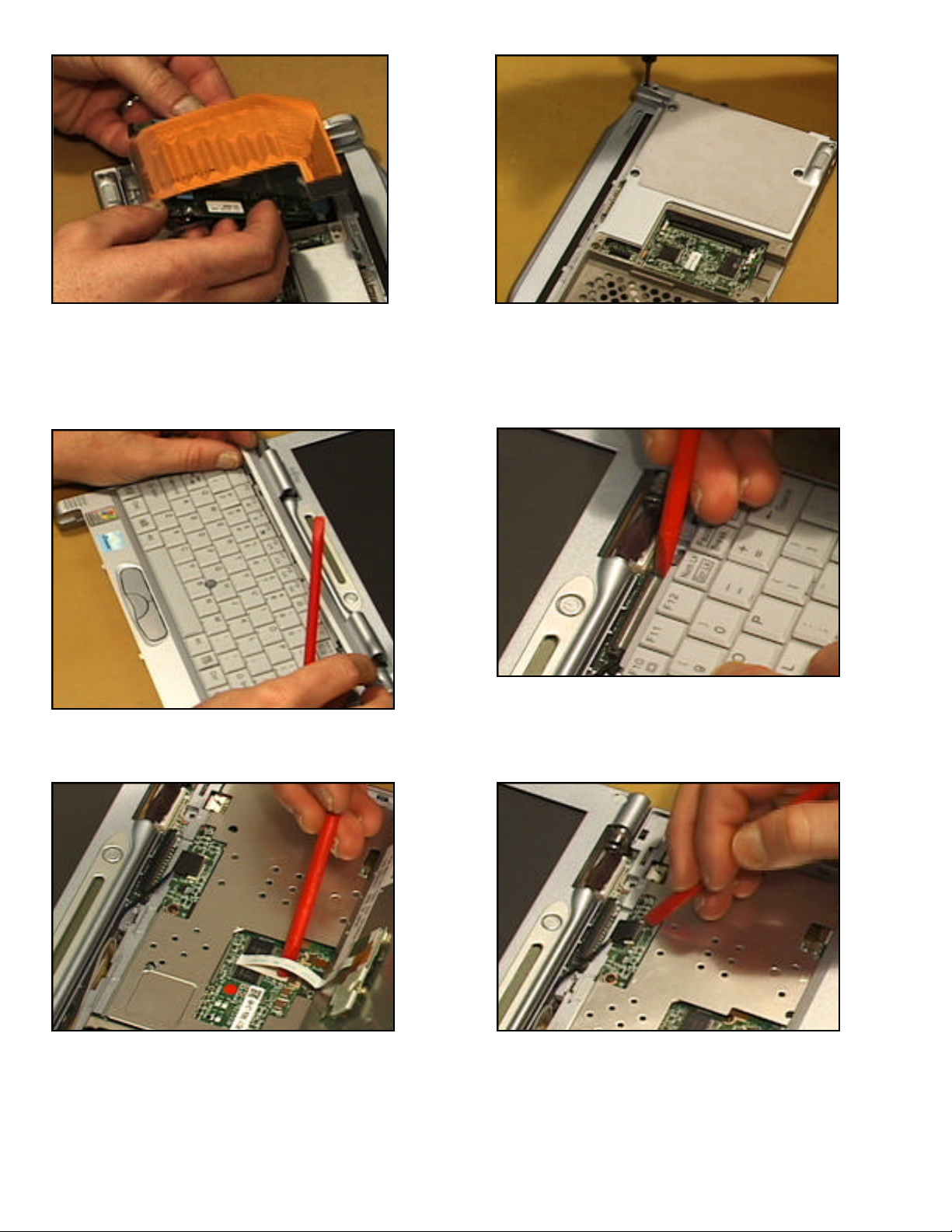
5. Detach the hard disk drive’s flex
cable and lift the drive from its bay.
7. Pry up and remove the hinge cover.
6. Remove seven case screws. Pry off
the unit’s feet and remove the two
screws beneath.
8. Underneath, unlock and remove the
keyboard’s flex cable.
9. Slide the keyboard forward and tilt
it up. Detach the cable to the pointing device and lift the keyboard off.
10. Detach the cable to the status
LCD.
2
Page 3

3
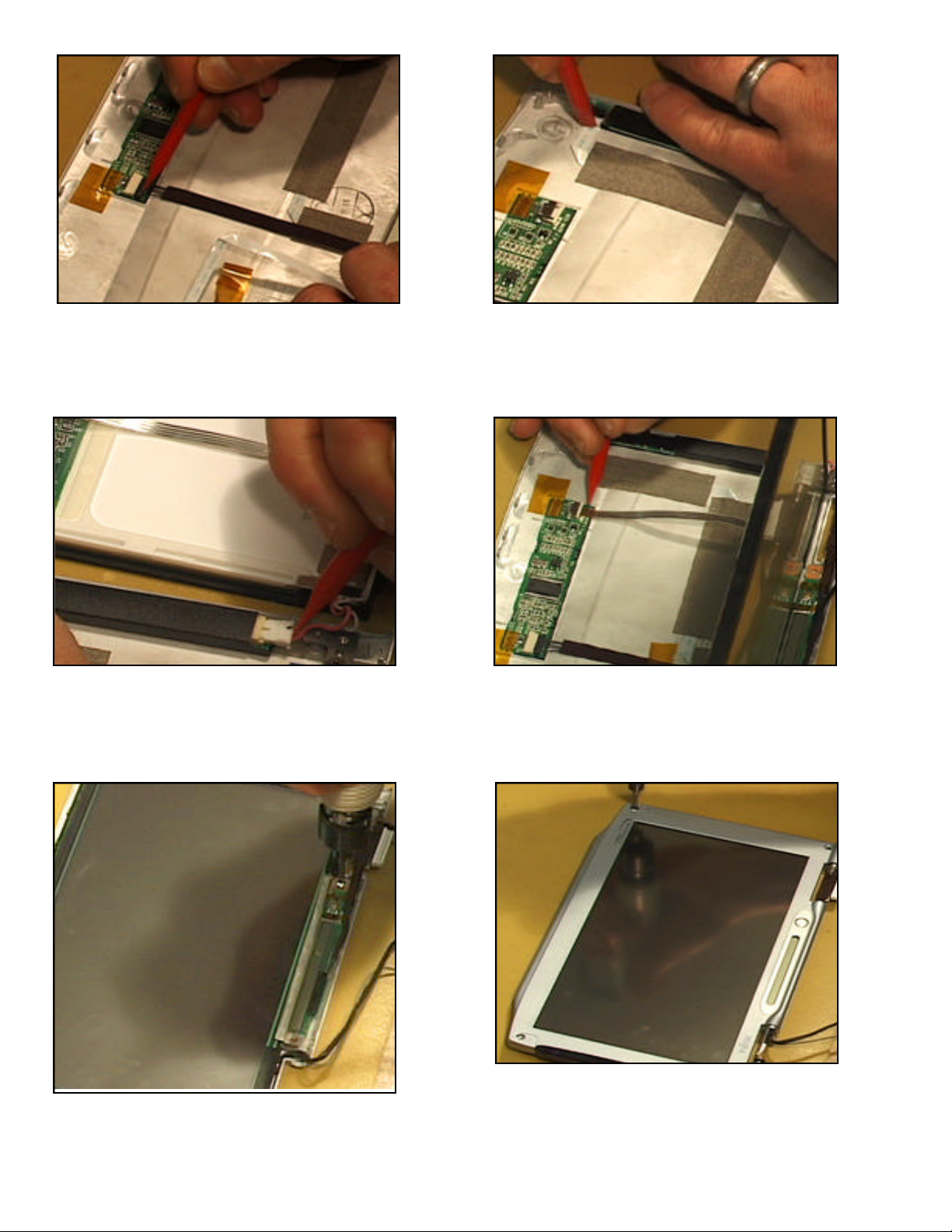
11. At the rear, remove the two hinge
screws.
12. Detach the main LCD cable. Lift
off the LCD.
13. Remove the screw securing the
upper cover.
15. Remove the screw securing the
heat sink and lift it off.
14. At the front, detach the cable from
the click assembly. Lift off the
upper cover. Remove the left and
right side panels.
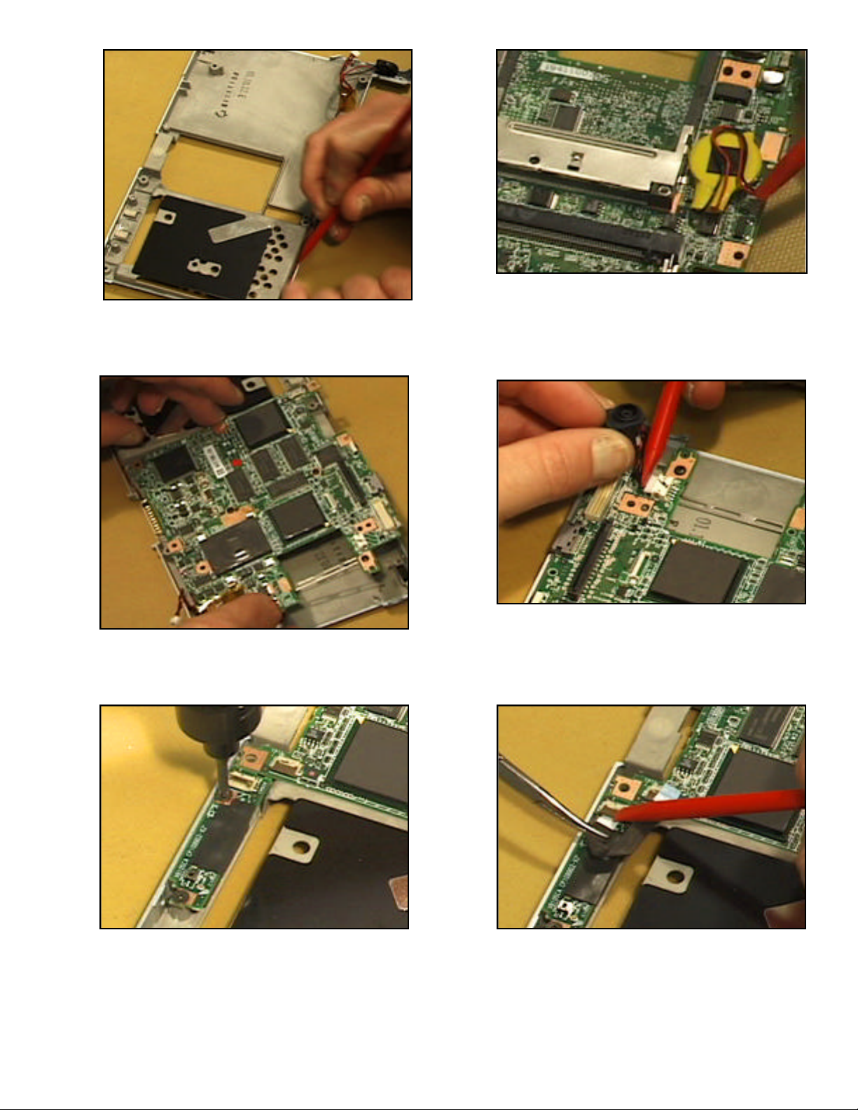
16. Unlock and remove the USB
cable.
Page 4

Remove the two screws securing
4
17.
the USB board and lift it off.
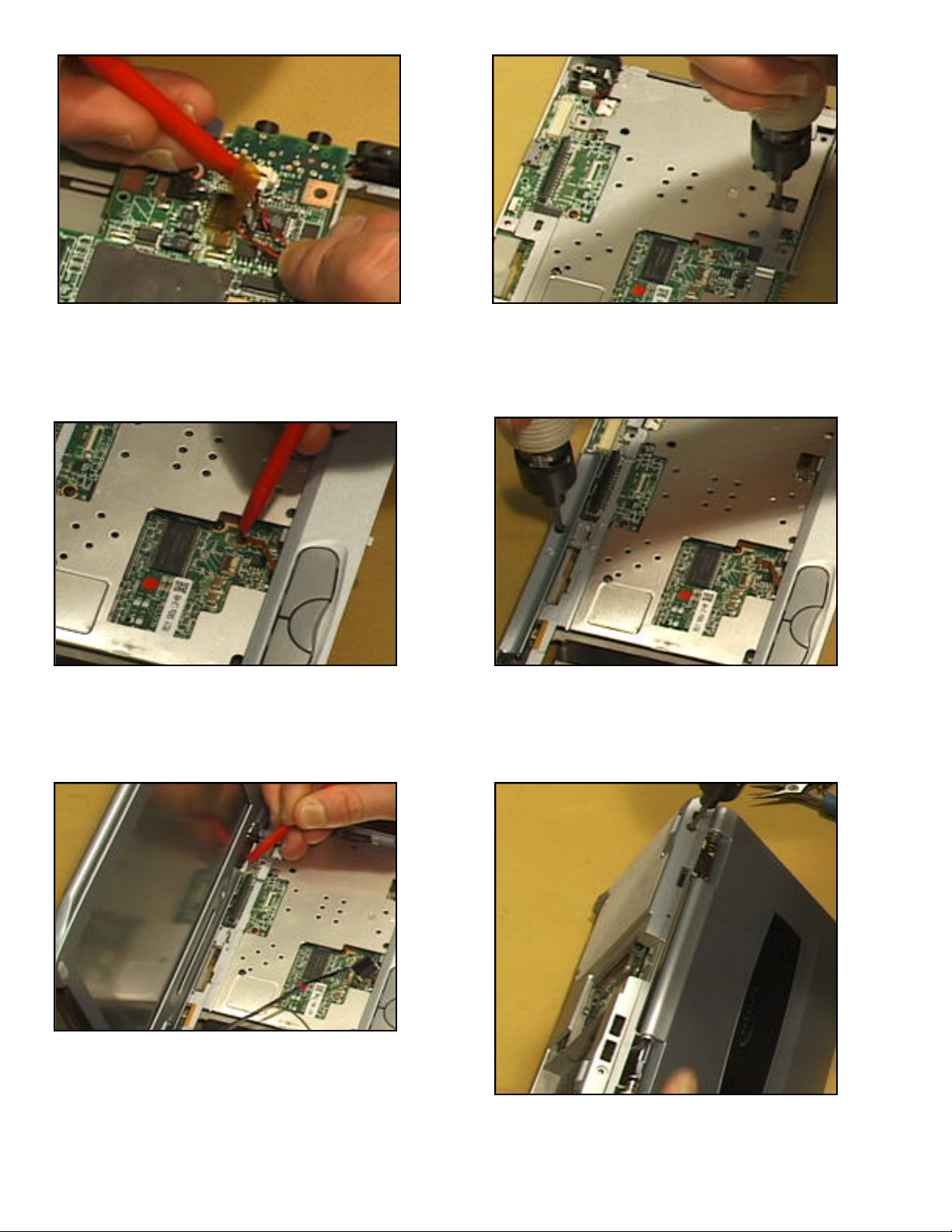
18. At the upper right, detach the DC
board cable.
19. Detach the speakers’ cable at the
lower right.
21. To disassemble the main LCD,
remove four corner screw caps
and the screws underneath.
20. Lift out the motherboard and turn
it over. Detach the bridge battery’s cable from the motherboard
and lift the battery off.
22. Gently pry the edge of the frame
to separate it from the rear cover
and lift it off.
Page 5

5
23. Remove two screws securing the
status LCD and lift off its cover.
24. Remove the screw securing the
LCD panel and tilt it up.
25. Detach the LCD’s cable from the
controller board.
27. Unlock and remove the inverter
cable. Slide the inverter card from
its sleeve.
Detach the LCD’s cable to the
26.
inverter card.
28. Unlock and remove the two status
cables from the back side of the
status LCD.
Page 6

29. Detach its cable to the control
board and lift out the status LCD.
30. Remove two screws securing the
wireless LAN antennae and left
hinge.
31. Detach the LAN cable and lift it
out.
32. Remove the antennae from its
cover. The disassembly of this
LifeBook is now complete.
6
Page 7

T e c h n i c a l P r o c e d u r e
7
LifeBook P-103x
Assembly Procedure
1. Fit the wireless LAN antennae into
its cover and position it in the rear
cover. Secure it with two screws.
3. Insert and lock the LAN’s status
cable.
2. Position its cable and secure the
hinge.
4. On the underside of the status LCD
attach its two cables.
Page 8
5. Attach also the status LCD’s main
8
cable to the controller card.
6. Slide the inverter card into its
sleeve. Insert and lock its cable.
7. Place the LCD panel next to the
rear cover so that you can attach its
cable to the inverter card.
9. Position and secure the cover to the
status LCD.
8. Tilt the LCD over so that you can
connect its cable to the controller
card. Tilt the LCD into the rear
cover.
10. Position the frame to the rear
cover and snap it into place.
Secure the frame with four screws
and replace the screw caps.
Page 9
9
11. Place the speakers into the lower
cover and position their cable.
13. Maneuver the motherboard into
the lower cover.
12. Connect the bridge battery to the
motherboard and position it.
14. Attach the cable from DC board
and position it.
15. Position and secure the USB
board with two screws.
16. Attach its cable.
Page 10
10
17. Connect the speakers’ cable on the
lower right.
18. Position the heat sink over the
motherboard and secure it.
19. Position the right and left side
panels. Position the upper cover
so that you can attach the click
assembly cable.
21. Lower the LCD onto the hinge
cover. Connect its cable.
20. Secure the cover.
22. At the rear, secure the two hinges
and replace the screw caps.
Page 11

11
23. Maneuver the LAN cable to the
underside of the unit so as to connect it to the modem card later.
24. Connect the status LCD cable to
the motherboard.
25. Position the keyboard so that you
can attach the cable to the pointing device.
27. Snap the hinge cover into place.
Close the unit and turn it over.
26. Tilt down the keyboard so that
you can insert and lock its data
cable.
Insert the modem card into its
28.
socket and press to lock it.
Connect the LAN cable.
Page 12

12
29. Replace two case screws between
the modem card and hard drive
bay.
31. Place the hard disk drive into its
bay and press to connect its flex
cable.
30. Place the modem cover so that
you can connect the modem cable
and then position the card.
32. Replace the drive’s cover and
secure it with two screws. Secure
the modem cover with three
screws.
33. Replace two case screws at the
rear and secure the feet. Continue
to replace five more case screws.
34. Press the battery into its bay until
it locks. The assembly of this
LifeBook is now complete.
 Loading...