

Page 1

BIOS
SECTION
P1000
Page 2
1. BIOS setup
Snapshots of the BIOS setup screen and the possible setup options is shown in the follo wing sections.
Underlined setup options show the default settings.
Columns between Selections and Note show the security level of each setup item. ‘S’ means that
the item needs the supervisor password security level and can not be changed with the user
password security level.
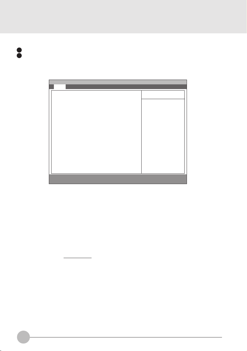
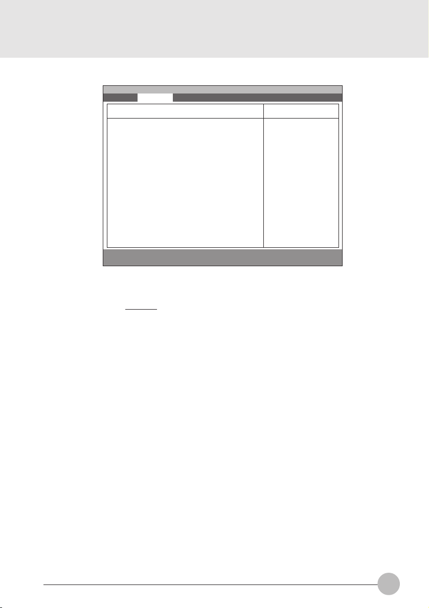
1.1 Main Menu
Main Advanced Security Power Boot Info Exit
System Time: [10:34:56]
System Date: [02/02/2001]
:Primary Master: [Toshiba MKI516AP-(PM)]
Language: [English (US)]
F1 Help ↑↓ Select Item -/Space Change Value F9 Setup Defaults
ESCExit ←→ Select Menu Enter Select :Sub-MenuF10Save and Exit
PhoenixBIOS Setup Utility
Figure 1-1 Main menu
Item Specific Help
Adjust calendar clock
<Tab>, <Shift-Tab>, or
<Enter> selects field.
metIputeSsnoitceleS)pleHcificepSmetI(etoN
emiTmetsyS95:95:32ot00:00:00.kcolcradnelactsujdA
etaDmetsySot1891/10/10
9902/13/21
retsaMyramirPPA615IKMabihsoT .ecivedIPATA/ATAretsamyramirperugifnoC
egaugnaL)SU(hsilgnE
)PJ(xxxxxx
2
.dleifstceles>retnE<ro,>baT-tfihS<,>baT<
.kcolcradnelactsujdA
.dleifstceles>retnE<ro,>baT-tfihS<,>baT<
.ecivedIPATA/ATAserugifnoC
neewtebsreffidgnittestluafedehT
.ledomesenapaJdnaledomnaeporuE/SU
.SOIBehtrofegaugnalyalpsidehttceleS
snoitpounemniaM1-1elbaT
Page 3
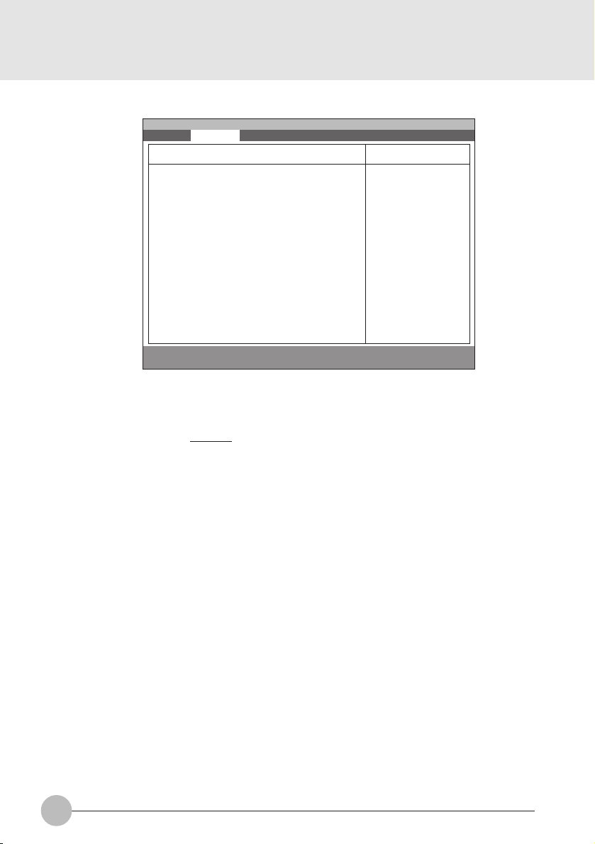
1.1.1 Main - Primary Master and Primary Slave Menu
Main Advanced Security Power Boot Info Exit
Primary Master [Fujitsu MHK2060AT]
PhoenixBIOS Setup Utility
Item Specific Help
Type: [Auto]
Maximum Capacity: 15097 MB
Multi-Sector Transfers: [16 Sectors]
LBA Mode Control: [Enabled]
PIO Transfer Mode: [Fast PIO 4]
DMA Transfer Mode: [Ultra DMA 2]
F1 Help ↑↓ Select Item -/Space Change Value F9 Setup Defaults
ESCExit ←→ Select Menu Enter Select :Sub-MenuF10Save and Exit
Figure 1-2 Main - Primary Master and Primary Slave Menu
metIputeSsnoitceleS)pleHcificepSmetI(etoN
epyTotuA
enoN
MOR-DC
elbavomeRIPATA
resU
srednilyC53556ot0S detcelessi’otuA‘nehwsraeppametisihT
sdaeH61ot1S detcelessi’otuA‘nehwsraeppametisihT
Select ATA/ATAPI
drive installed here.
[Auto]
The BIOS auto-type
the drive on boot
time.
Except [Auto]
You enter parameters
of the drive.
[None]
The drive is disabled.
.ereh
.erehdellatsni
si’otuA‘fI.epytecivedIPATA/ATAtceleS
tadeifitnediyllacitamotuasiepyteht,detceles
tuoyrractonseodtI.SOIBehtybTSOP
foesacehtniyalpsidrotceS/daeH/rednilyC
’enoN‘fI.edomotuAnehwDDH-BG4.8revo
odsmetiputesgniwollofehtfolla,detcelessi
nacuoy,detcelessi’resU‘nehW.raeppaton
.srotceSdnasdaeH,srednilyCyficeps
evirdksid-drahfosretemarapretneuoy=resU
.noitcennocsihttadellatsni
dellatsnievirdIPATA/ATAsepytotua=otuA
.erehdellatsnisievirdMOR-DCa=MOR-DC
sievirdksidelbavomer=elbavomeRIPATA
ro,ksiddrahsadeifitnedisiepytehtdna
,detcelessi’resU‘nehW.detcelessi’resU‘
.eulavehtegnahcnacuoy
.srednilyCforebmunehtyficepS
ro,ksiddrahsadeifitnedisiepytehtdna
,detcelessi’resU‘nehW.detcelessi’resU‘
.eulavehtegnahcnacuoy
.sdaeHforebmunehtyficepS
3
Page 4

Setup Item
Sectors
Maximum Capacity
Multi-Sector
Transfers
Selections
0 to 63
xxxx MB
Disabled
2 Sectors
4 Sectors
8 Sectors
16 Sectors
32 Sectors
64 Sectors
128 Sectors
Note (Item Specific Help)
This item appears when ‘Auto’ is selected and
S
the type is identified as hard disk, or ‘User’ is
selected. When ‘User’ is selected, you can
change the value.
Specify the number of Sectors.
Display maximum capacity calculated from
parameters of hard disk when ‘Auto’ is
selected and the type is identified as hard
disk, or ‘User’ is selected.
This option can not be changed when ‘Auto’
S
is selected.
Specify the number of sectors per block for
multiple sector transfer .
LBA Mode Control
PIO T ransf er Mode
DMA T ransf er Mode
Table 1-2 Main - Primary Master and Primary Slave Menu options
Disabled
Enabled
Standard
Fast PIO 1
Fast PIO 2
Fast PIO 3
Fast PIO 4
Disabled
Multiword DMA 1
Multiword DMA 2
Ultra DMA 0
Ultra DMA 1
Ultra DMA 2
This option can not be changed when ‘Auto’
S
is selected.
Enabling LBA causes Logical Block
Addressing to be used in place of Cylinders,
Heads & Sectors.
This option can not be changed when ‘Auto’
S
is selected. Multi-word DMA is automatically
set to mode 1 for ‘Fast PIO 1’, ‘Fast PIO 2’,
‘Fast PIO 3’ and set to mode 2 for ‘Fast PIO
4’.
Selects the method of moving data to/from
the drive. Autotype the drive to select the
optimum transfer mode.
You can not change this option when ‘Auto’ is
S
selected.
Selects the Ultra DMA mode used for moving
data to/from the drive. Autotype the drive to
select the optimum transfer mode.
4
Page 5
1.2 Advanced Menu
Main Advanced Security Power Boot Info Exit
Plug & Play O/S [Yes]
:Keyboard/Mouse Features
:Video Features
:Internal Devices Configurations
:PCI Configuration
:CPU Features
:USB Features
:Event Logging
F1 Help ↑↓ Select Item -/Space Change Value F9 Setup Defaults
ESCExit ←→ Select Menu Enter Select :Sub-MenuF10Save and Exit
PhoenixBIOS Setup Utility
Figure 1-3 Advanced menu
metIputeSsnoitceleS)pleHcificepSmetI(etoN
S/OyalP&gulPoN
seY
esuoM/draobyeK
serutaeF
serutaeFoediV .serutaefoedivdnayalpsidserugifnoC
eciveDlanretnI
snoitarugifnoC
noitarugifnoCICP ICPerugifnocotsunemputeslanoitiddA
SyalP&gulPagnisuerauoyfi’seY‘tceleS
Item Specific Help
[No]
The BIOS configures
also non-boot devices.
Select if you are
using a non-Plug &
Play OS or a non-ACPI
OS
[Yes]
The BIOS configures
only boot devices.
.secivedtoob-non
.secived
.metsysgnitarepoelbapac
erugifnocotSOIBehtdeenuoyfi’oN‘tceleS
.serutaefesuom/draobyekputeS
.secivedlanretnirehtoserugifnoC
serutaeFUPC .serutaefUPCerugifnoC
serutaeFBSU .serutaefBSUerugifnoC
gniggoLtnevE .serutaefgniggoltneveerugifnoC
snoitpounemdecnavdA3-1elbaT
5
Page 6
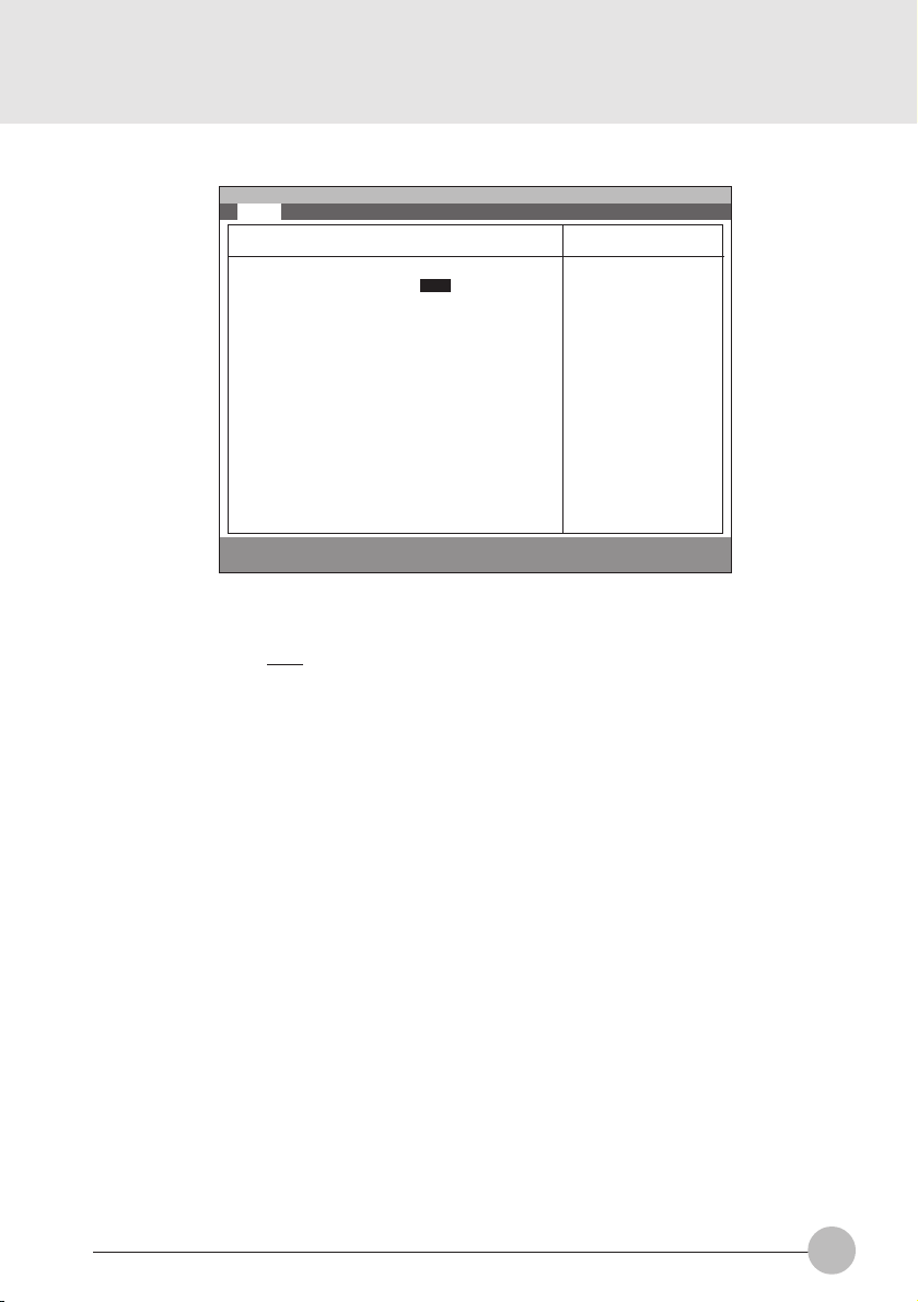
1.2.2 Advanced - Keyboard/Mouse Features Menu
Main Advanced Security Power Boot Info Exit
PhoenixBIOS Setup Utility
Keyboard/Mouse Features
Item Specific Help
Setup Item
Numlock
Internal Pointing
Device
Numlock: [Auto]
Internal Pointing Device [Always Enabled]
F1 Help ↑↓ Select Item -/Space Change Value F9 Setup Defaults
ESCExit ←→ Select Menu Enter Select :Sub-Menu F10Save and Exit
Selects power-on
state for Numlock.
Figure 1-4 Advanced - Keyboard/Mouse Features menu
Selections
Auto
Note (Item Specific Help)
S
Selects Power-on state for Numlock.
On
Off
Manual Setting
Always Enabled
Always Disabled
[Manual Setting]
Can be enabled or disabled by Hot key.
[Always Enabled]
[Always Disabled]
Always enabled or disabled.
6
Page 7
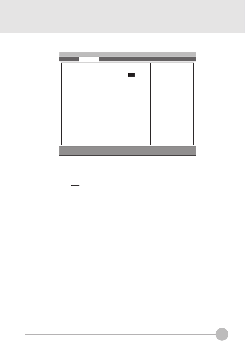
1.2.3 Advanced - Video Features Menu
Main Advanced Security Power Boot Info Exit
PhoenixBIOS Setup Utility
Video Features
Item Specific Help
Setup Item
Compensation
Compensation: [Disabled]
F1 Help ↑↓ Select Item -/Space Change Value F9 Setup Defaults
ESCExit ←→ Select Menu Enter Select :Sub-MenuF10Save and Exit
Select Compensation
Figure 1-5 Advanced - Video Features menu
Selections
Disabled
Note (Item Specific Help)
Select compensation.
Enabled
Table 1-5 Advanced - Video Features menu
7
Page 8
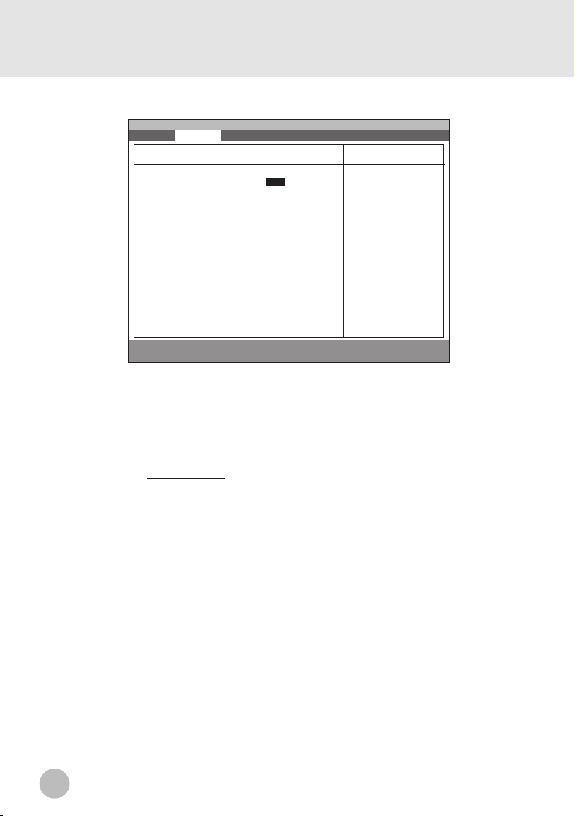
1.2.4 Advanced - Internal Device Configurations.
Main Advanced Security Power Boot Info Exit
Internal Device Configuration
IDE Controller: [Enabled]
F1 Help ↑↓ Select Item -/Space Change Value F9 Setup Defaults
ESCExit ←→ Select Menu Enter Select :Sub-MenuF10Save and Exit
PhoenixBIOS Setup Utility
Figure 1-6 Advanced - Internal Device Configurations
Item Specific Help
Setup Item
IDE Controller
8
Selections
Disabled
Note (Item Specific Help)
Enabled/Disable IDE Controller.
Enabled
Table 1-6 Advanced - Internal Device Configurations options
Page 9

1.2.5 Advanced - PCI Configuration Menu
Main Advanced Security Power Boot Info Exit
PhoenixBIOS Setup Utility
PCI Configuration
Item Specific Help
Setup Item
IRQ Reservation
:IRQ Reservation
F1 Help ↑↓ Select Item -/Space Change Value F9 Setup Defaults
ESCExit ←→ Select Menu Enter Select :Sub-Menu F10Save and Exit
Reserve specific
IRQs for use by
legacy ISA devices.
Figure 1-7 Advanced - PCI Configuration menu
Selections Note (Item Specific Help)
Reserve specific IRQs for use by legacy ISA
devices.
Table 1-7 Advanced - PCI Configuration menu options
9
Page 10

1.2.5.1 Advanced - PCI Configuration - IRQ Reservation Menu
Setup Item
IRQ 3
IRQ 4
IRQ 5
IRQ 7
IRQ 9
IRQ 10
Main Advanced Security Power Boot Info Exit
IRQ 3: [Available]
IRQ 4: [Available]
IRQ 5: [Available]
IRQ 7: [Available]
IRQ 9: [Available]
IRQ 10: [Available]
IRQ 11: [Available]
IRQ 15: [Available]
F1 Help ↑↓ Select Item -/Space Change Value F9 Setup Defaults
ESCExit ←→ Select Menu Enter Select :Sub-MenuF10Save and Exit
PhoenixBIOS Setup Utility
IRQ Reservation
Item Specific Help
Reserve the
specified IRQ for
use by legacy ISA
devices.
Figure 1-8 Advanced - PCI Configuration - IRQ Reservation menu
Selections
Available
Reserved
Note (Item Specific Help)
If [Reserved] is selected, the BIOS reserves
S
IRQ 3 for use by legacy ISA devices and does
not use it for embedded PCI or ISA devices.
IRQ 3 is removed from the IRQ bitmap in the
PCI IRQ routing table.
Reserve the specified IRQ for use by legacy
ISA devices.
Available
Reserved
Reserves IRQ 4.
S
Reserve the specified IRQ for use by legacy
ISA devices.
Available
Reserved
Reserves IRQ 5.
S
Reserve the specified IRQ for use by legacy
ISA devices.
Available
Reserved
Reserves IRQ 7.
S
Reserve the specified IRQ for use by legacy
ISA devices.
Available
Reserved
Reserves IRQ 9.
S
Reserve the specified IRQ for use by legacy
ISA devices.
Available
Reserved
Reserves IRQ 10.
Reserve the specified IRQ for use by legacy
ISA devices.
10
Page 11

Setup Item
IRQ 11
IRQ 15
Selections
Available
Reserved
Available
Reserved
Table 1-8 Advanced - PCI Configuration - IRQ Reservation menu options
Note (Item Specific Help)
Reserves IRQ 11.
S
Reserve the specified IRQ for use by legacy
ISA devices.
Reserves IRQ 15.
S
Reserve the specified IRQ for use by legacy
ISA devices.
11
Page 12

1.2.5.2 Advanced - CPU Features Menu
Main Advanced Security Power Boot Info Exit
PhoenixBIOS Setup Utility
USB Features
Item Specific Help
Processor Serial number : [Disabled]
F1 Help ↑↓ Select Item -/Space Change Value F9 Setup Defaults
ESCExit ←→ Select Menu Enter Select :Sub-Menu F10Save and Exit
Figure 1-9 Advanced - USB Features Menu
1.2.5.3 Advanced - USB Features Menu
Main Advanced Security Power Boot Info Exit
USB Floppy Disk: [Enabled]
PhoenixBIOS Setup Utility
USB Features
[Disabled]
Processor Serial
Number feature is
disabled.
[Enabled]
Processor Serial
number is enabled.
Item Specific Help
[Disabled]
Legacy Floppy
Emulation is
disabled.
[Enabled]
Legacy Floppy
Emulation is enabled
and USB floppy is
available without
USB aware OS.
12
F1 Help ↑↓ Select Item -/Space Change Value F9 Setup Defaults
ESCExit ←→ Select Menu Enter Select :Sub-Menu F10Save and Exit
Figure 1-10 Advanced - USB Features Menu
Page 13

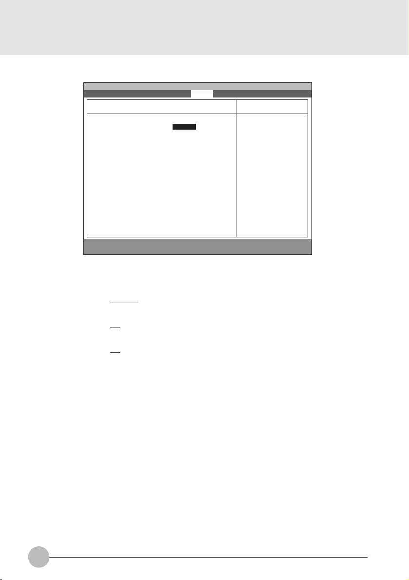
1.2.6 Advanced - Event Logging Menu
Main Advanced Security Power Boot Info Exit
Event Log Capacity: Space Available
Event Log Validity: Valid
View Event Log: [Enter]
Event Logging: [Enabled]
Clear all event logs: [No]
Mark Events as Read: [Enter]
F1 Help ↑↓ Select Item -/Space Change Value F9 Setup Defaults
ESCExit ←→ Select Menu Enter Select :Sub-MenuF10Save and Exit
Setup Item
Event log capacity
Event log validity
View Event Log:
Event Logging
Clear all event logs
Mark Events as Read:
PhoenixBIOS Setup Utility
Event Logging
System Boot Event: [Disabled]
Item Specific Help
[No]
Event logs will not
be cleared at the
next boot.
[Yes]
All event logs will
be cleared at the
next boot. The value
is reset to [No]
after clearing logs.
Figure 1-11 Advanced - Event Logging menu
Selections
Note (Item Specific Help)
Display event log capacity.
Display event log validity.
[Enter]
Press Enter key to view the contents of the
event log.
Disabled
Enables Event Logging.
Enabled
‘Yes’ clears all DMI event logs at next boot.
No
The value is reset to ‘No’ after clearing logs.
Yes
[Enter]
Press Enter key to mark all events currently
in the event log as read. Marked events will
not be displayed from the next “View Event
Log”.
Table 1-12 Advanced - Event Logging menu options
13
Page 14

1.3 Security Menu
Main Advanced Security Power Boot Info Exit
Supervisor Password Is: Clear
User Password Is: Clear
Set Supervisor Password [Enter]
Set User Password [Enter]
Minimum User Password Length [0]
Password on Boot: [Disabled]
Password on Resume: [Disabled]
Boot from Removable Media: [All]
Floppy Disk Access: [All]
:Hard Disk Security
:Owner Information
Hard Disk Boot Sector: [Normal]
F1 Help ↑↓ Select Item -/Space Change Value F9 Setup Defaults
ESCExit ←→ Select Menu Enter Select :Sub-MenuF10Save and Exit
Setup Item
Supervisor Password Is
User Password Is
Set Supervisor Password
Set User Password
Floppy Disk Access
Password on Boot
Password on Boot
Hardisk boot
sector
PhoenixBIOS Setup Utility
Figure 1-13 Security menu
Selections
All
Supervisor Only
Disabled
Enabled
Disabled
Enabled
Normal
Write Protect
Item Specific Help
Press <Enter> key to
set Supervisor
Password to enable
any password
features.
Then password entry
is required to enter
BIOS Setup.
Note (Item Specific Help)
Display the setting of Supervisor password.
Display the setting of User password.
Supervisor Password controls access to the
S
setup utility.
User password can be set after Supervisor
password is set.
User Password controls access to the system
at boot.
This item can be set with Supervisor
S
password security level. When ‘Supervisor
Only’ is selected, floppy diskette drive is not
available with User password security level.
Controls access to diskette drives.
When Password on boot is ‘Enabled’, the
BIOS requires a password on OS boot.
Enables password entry on boot.
When Password is set with superior pass word
security level, Password on Resume can be
enabled.
Write protects boot sector on hard disk to
S
protect against viruses.
14
Page 15

Setup Item
Hardisk security
Selections
Note (Item Specific Help)
Primary Master
Disabled
Enabled
Table 1-13 Security menu options
1.3.1 Set Supervisor Password
Supervisor Password Is: Clear
Set Supervisor Password
Enter New Password [ ]
Confirm New Password [ ]
Supervisor Password Is: Set
Set Supervisor Password
Enter Current Password [ ]
Enter New Password [ ]
Confirm New Password [ ]
1.3.3 Security- Owner Information
Main Advanced Security Power Boot Info Exit
S
1.3.2 Set User Password
PhoenixBIOS Setup Utility
Owner Information
This item can be set with Supervisor
password security level. When ‘Enabled’ is
selected, the data of the hard disk are
protected with the password lock feature of
the drive. You can not read any data on the
drive if it is not installed in the same system
as it is locked with the password.
Enables fixed disk security.
User Password Is: Clear
Set User Password
Enter New Password [ ]
Confirm New Password [ ]
User Password Is: Set
Set User Password
Enter Current Password [ ]
Enter New Password [ ]
Confirm New Password [ ]
Item Specific Help
Owner Information Is: Clear
Set Owner Information: [Enter]
Foreground Color: [Gray]
Background Color: [Black]
F1 Help ↑↓ Select Item -/Space Change Value F9 Setup Defaults
ESCExit ←→ Select Menu Enter Select :Sub-MenuF10Save and Exit
Figure 1-14 Security- Owner Information
15
Page 16

1.4 Power Menu
Main Advanced Security Power Boot Info Exit
Power Savings: [Customized]
Hard Disk Timeout: [Off]
Video Timeout: [Off]
Standby Timeout: [4 Minutes]
Auto Suspend Timeout: [15 Minutes]
Suspend Mode: [Suspend]
Auto Save To Disk: [Off]
Resume On Modem Ring: [Off]
Resume On Time: [Off]
Resume Time: [00:00:00]
:Advanced Features
F1 Help ↑↓ Select Item -/Space Change Value F9 Setup Defaults
ESCExit ←→ Select Menu Enter Select :Sub-MenuF10Save and Exit
PhoenixBIOS Setup Utility
Item Specific Help
Select Power
Management Mode.
Choosing modes
changes system power
management settings.
Maximum Power Savings
conserves the
greatest amount of
system power while
Maximum Performance
conserves power but
allows greatest
system performance.
To alter these
settings, choose
Customize. To turn
off power management,
choose Disable.
Figure 1-15 Power menu
Setup Item
Power Savings
Hard Disk Timeout
Display Timeout
16
Selections
Disabled
Customized
Maximum Po wer
Savings
Maximum Performance
Off
30 Seconds
1 Minute
2 Minutes
4 Minutes
6 Minutes
8 Minutes
10 Minutes
15 Minutes
20 Minutes
Off
2 Minutes
4 Minutes
6 Minutes
8 Minutes
10 Minutes
15 Minutes
20 Minutes
Note (Item Specific Help)
Select Power Management Mode. Choosing
modes changes system power management
settings. Maximum P ow er Savings conserves
the greatest amount of system power while
Maximum Performance conserves power b ut
allows greatest system performance. To alter
these settings, choose Customized. To turn
off power management, choose Disabled.
Amount of time the hard disk needs to be
inactive before it is turned off.
Amount of time the user input devices need
to be inactive before the screen is turned off.
Page 17

Setup Item
Standby Timeout
Selections
Off
1 Minute
2 Minutes
4 Minutes
6 Minutes
8 Minutes
12 Minutes
16 Minutes
Note (Item Specific Help)
Amount of time the system needs to be
inactive before entering the Standby Mode.
Standby Mode turns off various devices in the
system, including the screen, until you start
using the computer again.
Auto Suspend
Timeout
Suspend Mode
Auto Save To Disk
Resume On Modem
Ring
Resume On Time
Resume Time
Advanced Features
Off
5 Minutes
10 Minutes
15 Minutes
20 Minutes
30 Minutes
40 Minutes
60 Minutes
Suspend
Save To Disk
Off
After 1 Hour
Off
On
Off
On
00:00:00 to 23:59:59
Table 1-15 Power menu options
Amount of time the system needs to be
inactive before entering the Suspend Mode.
Select the type of Suspend Mode. If you
choose Save To Disk the system will sav e its
state to disk and power off. If you choose
Suspend the system will save its state but
remain in a low power mode. If you choose
Suspend then you also have the option of
choosing Auto Save To Disk.
Turn on or off the Auto Save To Disk feature.
When Auto Save To Disk is turned on, the
system will save its state to disk and then
power off after being in Suspend mode for a
period of time.
Turning this feature on will wake the system
up when an incoming call is detected on your
modem in Suspend Mode.
Turning this feature on will wake the system
up at ‘Resume Time’ from Suspend Mode.
Specify the time when the system is to wake
up. <Tab>, <Shift-Tab>, or <Enter> selects
field.
Allows editing of advanced power
management features.
Power Saving Mode Hard Disk Display Standby Auto Suspend
Disabled Off Off Off Off
Customized Off Off 4 Minutes 15 Minutes
Maximum Power Savings 30 Seconds 2 Minutes 1 Minute 5 Minutes
Maximum Performance Off Off Off 15 Minutes
Table 1-16 Preset values for each Power Saving Modes
17
Page 18
1.4.1 Power - Advanced Features Modes
Main Advanced Security Power Boot Info Exit
PhoenixBIOS Setup Utility
Advanced Features
Item Specific Help
F1 Help ↑↓ Select Item -/Space Change Value F9 Setup Defaults
ESCExit ←→ Select Menu Enter Select :Sub-MenuF10Save and Exit
Setup Item
SUS/RES Switch
Lid Closure Suspend
Lid Open Resume
Suspend/Resume Switch: [Enabled]
Lid Closure Suspend: [On]
Lid Open Resume: [On]
Configures the
Suspend/Resume
switch.
Figure 1-17 Power - Advance Features menu
Selections
Disabled
Note (Item Specific Help)
Set the SUS/RES Switch.
Enabled
Off
Set the Lid Closure Suspend.
On
Off
Set the Lid Open Resume.
On
Table 1-17 Power - Advanced Features menu options
18
Page 19

1.5 Boot Menu
Main Advanced Security Power Boot Info Exit
Quick Boot: [Enabled]
Boot-time Diagnostic Screen: [Disabled]
:Boot Device Priority
F1 Help ↑↓ Select Item -/Space Change Value F9 Setup Defaults
ESCExit ←→ Select Menu Enter Select :Sub-Menu F10Save and Exit
PhoenixBIOS Setup Utility
Item Specific Help
[Disabled]
All diagnostic test
will be done.
[Enabled]
Some diagnostic tests
may be skipped while
booting to speed up.
[Auto]
Diagnostic tests will
be automatically
skipped or done
according to the
order of the ACPI OS.
Figure 1-18 Boot menu
Setup Item
QuickBoot Mode
Boot-time Diagnostic
Screen
Boot Device Priority
Selections
Disabled
Enabled
Auto
Disabled
Enabled
Table 1-18 Boot menu options
Note (Item Specific Help)
Allows the system to skip certain tests while
S
booting. This will decrease the time needed
to boot the system.
Display the diagnostic screen during boot.
S
Select the search order for the types of boot
devices.
19
Page 20

1.5. 1 Boot - Boot Device Priority Menu
Main Advanced Security Power Boot Info Exit
Floppy Disk Drive
+Hard Disk Drive
F1 Help ↑↓ Select Item -/Space Change Value F9 Setup Defaults
ESCExit ←→ Select Menu Enter Select :Sub-MenuF10Save and Exit
PhoenixBIOS Setup Utility
Boot Device Priority
Figure 1-19 Boot - Boot Device Priority menu
Setup Item
Bootable devices available are listed. The
following devices will appear depending on
the hardware configuration.
[Floppy Disk Drive]
[Hard Drive]
Table 1-19 Boot - Boot menu Device Priority options
Item Specific Help
The top device has
the highest priority.
<Enter> expands or
collapses devices
with a + or -.
<Ctrl+Enter> expands
all.
<↑> or <↓> select a
device.
<+>/<Space> or <->
move the device up or
down.
<Shift+1> enables or
disables adevice.
Note (Item Specific Help)
Use <↑> or <↓> to select a device, then press
<+> or <Space> to move it up the list, or <–>
to move it down the list. Press <Esc> to exit
this menu.
1.5. 1.1 Boot Menu at POST
The following pop up menu will appear when you hit the F12 k e y during POST. The de vice list in this
pop up menu are same as the list in the Boot Device Priority menu.
Boot Menu
1. Floppy Disk Drive
2. Hard Drive
<Enter Setup>
20
Page 21

1.6 Info Menu
Main Advanced Security Power Boot Info Exit
BIOS Version: 1.XX
BIOS Date: XX/XX/2000
BIOS Area: E800h - FFFFh
CPU Type: Transmeta TM5400 processor
CPU Speed: 533 MHz
L1 Cache: 128 KB
L2 Cache: 256 KB
Total Memory: 112 MB
CMS Mode: Normal
CMS Revision: 4.1.7-7-95
OEM ID: FJCFG-0002000101
F1 Help ↑↓ Select Item -/Space Change Value F9 Setup Defaults
ESCExit ←→ Select Menu Enter Select :Sub-Menu F10Save and Exit
PhoenixBIOS Setup Utility
Item Specific Help
Figure 1-20 Info menu
Information Item
BIOS Version
BIOS Date
BIOS Area
CPU Type
CPU Speed
L1 Cache
L2 Cache
Total Memory
CMS mode
CMS Revision
OEM ID
Values
n.nn
MM/DD/YYYY
xxxxh – FFFFh
T r ansmeta TM5400
processor
533 MHz
128 KB
256 KB
112 MB
Normal
4.1.7-7-95
FJCFG-000200010
Table 1-21 Info menu items
Note
This area can not be used as UMB.
21
Page 22

1.7 Exit menu
Main Advanced Security Power Boot Info Exit
Exit Saving Changes
Exit Discarding Changes
Load Setup Defaults
Discard Changes
Save Changes
F1 Help ↑↓ Select Item -/Space Change Value F9 Setup Defaults
ESCExit ←→ Select Menu Enter Select :Sub-Menu F10Save and Exit
Setup Item
Exit Saving Changes
Exit Discarding Changes
Load Setup Defaults
PhoenixBIOS Setup Utility
Figure 1-22 Exit menu
Note (Item Specific Help)
Exit System Setup and save your changes to
CMOS.
Exit utility without saving Setup data to CMOS.
Load default values for all SETUP items.
Item Specific Help
Exit System Setup and
save your changes to
CMOS.
Discard Changes
Save Changes
22
Load previous values from CMOS for all
SETUP items.
Save Setup Data to CMOS.
Table 1-22 Exit menu options
Page 23

1.7.1 Exit Saving Changes
1.7.4 Discard Changes
Setup Confirmation
Save configuration changes and exit now?
[Yes] [No]
1.7.2 Exit Discarding Changes
Setup Warning
Configuration has not been saved!
Save before exiting?
[Yes] [No]
1.7.3 Load Set up Defaults
Setup Confirmation
Load previous configuration now?
[Yes] [No]
Setup Confirmation
Save configuration changes now?
[Yes] [No]
1.7.5 Save Changes
Setup Confirmation
Load default configuration now?
[Yes] [No]
23
Page 24
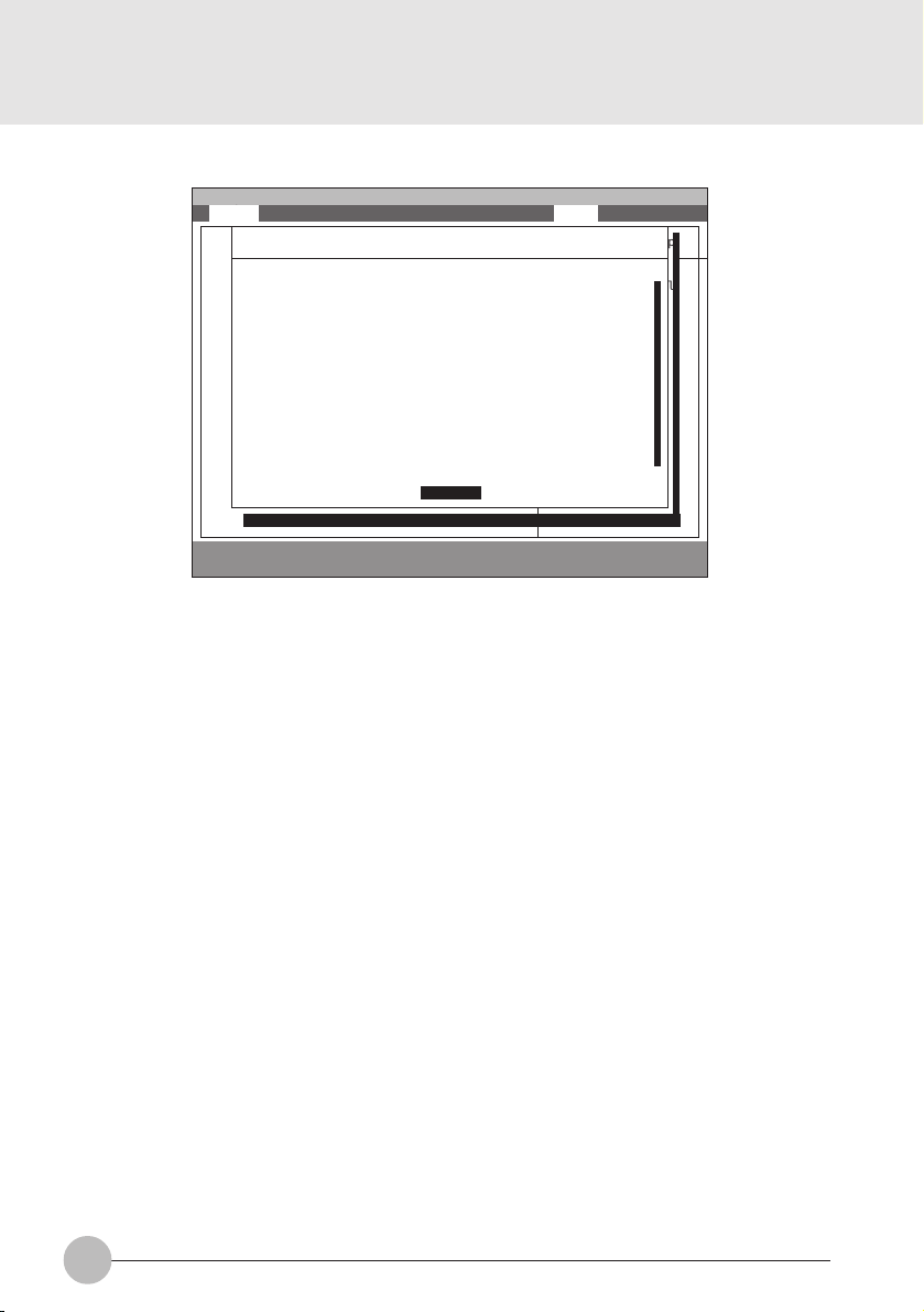
1.8 General Help
Main Advanced Security Power Boot Info Exit
Main
System Time: [12:34:56]
System Date: [06/02/1999]
Setup changes system behavior by modifying the BIOS
Legacy Diskette A: [1.44/1.25 MB 31/2”]
configuration. Selecting incorrect values may
cause system boot failure; load Setup Default values to
:Primary Master: [FUJITSU MHA2043AT]
recover.
:Secondary Master: [None]
:Secondary Master: [None]
<Up/Down> arrows select fields in current menu.
<Pgup/PgDn> moves to previous/next page on scrollable
System Memory: 640MB
menus.
Extended Memory: 31MB
<Home/End> moves to top/bottom item of current menu.
:Memory Cache
Within a field, <F5> or <–> selects next lower value and
Language: [English (US)]
<F6>, <+>, or <Space> selects next higher value.
F1 Help ↑↓ Select Item -/Space Change Value F9 Setup Defaults
ESCExit ←→ Select Menu Enter Select ➧Sub-Menu F10Save and Exit
PhoenixBIOS Setup Utility
General Help
[Continue]
Item Specific Help
<Tab>, <Shift-Tab or
or <Enter> selectld.
Figure 1-23 General Help
General Help
Setup changes system behavior by modifying the BIOS
configuration. Selecting incorrect values may
cause system boot failure; load Setup Default values to
recover.
<Up/Down> arrows select fields in current menu.
<PgUp/PgDn> moves to previous/next page on scrollable menus.
<Home/End> moves to top/bottom item of current menu.
:
Within a field, <F5> or <-> selects next lower value and
<F6>, <+>, or <Space> selects next higher value.
<Left/Right> arrows select menus on menu bar.
<Enter> displays more options for items marked with _.
<F9> loads factory installed Setup Default values.
<F10> saves current settings and exits Setup.
<Esc> or <Alt-X> exits Setup; in sub-menus, pressing these
keys returns to the previous menu.
<F1> or <Alt-H> displays General Help (this screen).
Table 1-23 Entire Text of General Help
24
Page 25

2. POST Diagnostic Screen
PhoneixBIOS 4.0 Release 6.0
Copyright 1985-1999 Phoenix Technologies Ltd.
All Rights Reserved
Fujitsu Notebook BIOS Version 1.xx
1995-2000 Copyright FUJITSU LIMITED 1998-1999.
Mouse Initialized
<F12>:Boot Menu / <F2>:BIOS Setup
Figure 2-1 Typical Diagnostic Screen
Normal Messages
0640K System Memory Passed
nnnnM Extended Memory Passed
nnnnK Memory Cache Passed
System BIOS shadowed
Video BIOS shadowed
Mouse initialized
Press <F2> to enter SETUP
Entering SETUP ...
Table 2-1 Normal Messages in Diagnostic Screen
Error Messages
System Memory Failed at offset: xxxx
Failing Bits: zzzz
Extended Memory Failed at offset: xxxx
Failing Bits: zzzz zzzz
System cache error - Cache disabled
Keyboard controller error
Keyboard error
Diskette drive A error
Failure Fixed Disk n
25
Page 26

Error Messages
System timer error
Real time clock error
System CMOS checksum bad - Default configuration used
Previous boot incomplete - Default configuration used
Press <F1> to resume,<F2> to Setup
Check date and time settings
Password locked: Fixed Disk n
No Save To Disk partition or file exists on Fixed Disk
- Save To Disk features is disabled.
Not enough Save To Disk partition or file exists on Fixed
Disk.
- Save To Disk feature is disabled.
Hard Disk Drive is not installed.
- Save To Disk feature is disabled.
Unknown Save To Disk error.
- Save To Disk feature is disabled.
Hard disk sector read function failed.
- Save To Disk feature is disabled.
Hard disk sector write function failed.
- Save To Disk feature is disabled.
Save To Disk partition or file corrupted.
- Save To Disk feature is disabled.
Fixed Disk is not installed. Cannot restore from disk.
To restore from disk : turn off system, install original
fixed disk and reboot.
Press <F1> to continue to boot without save to disk
data.
Fixed Disk has been changed. Cannot restore from disk.
To restore from disk : turn off system, install original fixed
disk and reboot.
Press <F1> to continue to boot without save to disk data.
26
Table 2-2 Error Messages in Diagnostic Screen
 Loading...