

Page 1

Copyright
Copyright
Fujitsu Limited has made every effort to ensure
the accuracy and completeness of this document.
However, as ongoing development efforts are
continually improving the capabilities of our
products, we cannot guarantee the accuracy of
the contents of this document. We disclaim
liability for errors, omissions, or future changes.
LifeBook is a trademark of Fujitsu Limited.
Microsoft, Windows, MS, MS-DOS, and Windows
NT are registered trademarks of the Microsoft
Corporation of the United States in the United
States and other countries.
Phoenix is a registered trademark of Phoenix
Technologies Corporation of the United States.
Copyright© 1981-1999 Microsoft Corporation, All
rights reserved.
Copyright© 1999 Phoenix Technologies, Ltd., All
rights reserved.
Other product names are trademarks or
registered trademarks of their respective
companies.
© Copyright 2003 Fujitsu Limited. All rights
reserved. No part of this publication may be
copied, reproduced, or translated, without the
prior written consent of Fujitsu Limited. No part
of this publication may be stored or transmitted
in any electronic form without the written consent
of Fujitsu Limited.
Operations are subject to the following two
conditions:
(1) This device may not be allowed to cause
harmful interference,
(2) This device must accept any interference
received, including interference that may
cause undesired operation.
Wesbite: www.pc-ap.fujitsu.com
DECLARATION OF CONFORMITY
according to FCC Part 15
This device complies with Part 15 of the FCC rules. Operations are subject to the following two conditions:
(1) This device must not be allowed to cause harmful interference, (2) This device must accept any
interference received, including interference that may cause undesired operation.
i
Page 2

IMPORTANT SAFETY
INSTRUCTIONS
1. Read these instructions carefully. Save these
instructions for future reference.
2. Follow all warnings and instructions marked
on the product.
3. Unplug this product from the wall outlet
before cleaning. Do not use liquid cleaners
or aerosol cleaners. Use a damp cloth for
cleaning.
4. Do not use this product near water.
5. Do not place this product on an unstable cart,
stand, or table. The product may fall, causing
serious damage to the product.
6. Slots and openings in the cabinet and the
back or bottom are provided for ventilation;
to ensure reliable operation of the product
and to protect it from overheating, these
openings must not be blocked or covered.
The openings should never be blocked by
placing the product on a bed, sofa, rug, or
other similar surface. This product should
never be placed near or over a radiator or
heat register, or in a built-in installation unless
proper ventilation is provided.
7. This product should be operated from the
type of power indicated on the marking label.
If you are not sure of the type of power
available, consult your dealer or local power
company.
8. This product is equipped with a 3-wire
grounding-type plug, a plug having a third
(grounding) pin. This will only plug into a
grounding-type power outlet. This is a safety
feature. If you are unable to insert the plug
into the outlet, contact your electrician to
replace your obsolete outlet. Do not defeat
the purpose of the grounding-type plug.
9. Do not allow anything to rest on the power
cord. Do not locate this product where
persons will walk on the cord.
10. If an extension cord is used with this product,
make sure that the total ampere rating of the
equipment plugged into the extension cord
does not exceed the extension cord ampere
rating. Also, make sure that the total rating
of all products plugged into the wall outlet
does not exceed 15 amperes.
11. Never push objects of any kind into this
product through cabinet slots as they may
touch dangerous voltage points that could
result in a fire or electric shock. Never spill
liquid of any kind on the product.
12. Do not attempt to service this product
yourself, as opening or removing covers may
expose you to dangerous voltage points or
other risks. Refer all servicing to qualified
service personnel.
13. Unplug this product from the wall outlet and
refer servicing to qualified service personnel
under the following conditions:
a. When the power cord or plug is damaged
or frayed.
b. If liquid has been spilled into the product.
c. If the product has been exposed to rain or
water.
d. If the product does not operate normally
when the operating instructions are followed.
Adjust only those controls that are covered
by the operating instructions since improper
adjustment of other controls may result in
damage and will often require extensive
work by a qualified technician to restore the
product to normal condition.
e. If the product has been dropped or the
cabinet has been damaged.
f. If the product exhibits a distinct change in
performance, indicating a need for service.
ii
Page 3

14. CAUTION. When replacing the battery, be
sure to install it with the polarities in the
correct position. There is a danger of
explosion if the battery is replaced with
an incorrect type or is mistreated. Do not
recharge, disassemble or dispose of in
fire. Replace only with the same or
equivalent type recommeded by the
manufacturer. Dispose of the used battery
according to the manufacturer’s
instructions.
15. Use only the proper type of power supply
cord set (provided in your accessories box)
for this unit. It should be a detachable type:
UL listed/CSA certified, BS1363, ASTA,
SS145 certified, rated 10A 250V minimum,
VDE approved or its equivalent. Maximum
length is 15 feet (4.6 meters).
iii
Page 4

HIGH SAFETY REQUIRED USE
This Product is designed, developed and
manufactured as contemplated for general use,
including without limitation, general office use,
personal use, household use and ordinary
industrial use, but is not designed,developed and
manufactured as contemplated for use
accompanying fatal risks or dangers that, unless
extremely high safety is secured, could lead
directly to death, personal injury, severe physical
damage or other loss (hereinafter ‘High Safety
Required Use’), including without limitation,
nuclear power reaction core control in nuclear
atomic facility, airplane automatic aircraft flight
control, air traffic control, operation control in
mass transport control system, medical
instrument for life support system, missile
launching control in weapon system. You shall
not use this Product without securing the
sufficient safety required for the High Safety
Required Use.
DATA STORAGE MEDIA AND
CUSTOMER RESPONSIBILITIES
The only effective protection for the data stored
in a computer, such as on a hard disk, is for you,
Purchaser to regularly back up the data. Fujitsu
and its affiliates, suppliers, service providers and
resellers shall not be responsible for any software
programs, data or other information stored or
used on any media or part of any Product
returned to Fujitsu or its service providers for
Warranty Service or other repair, including but
not limited to the costs of recovering such
programs, data or other information. It is solely
your responsibility as the Purchaser to back up
any software programs, data, or information
stored on any storage media or any part of a
Product returned for Warranty Service or repair
to the designated service centers.
iv
Page 5

Copyright
AUSTRALIAN WARNINGS
WARNING
FOR SAFETY REASONS, ONLY CONNECT
EQUIPMENT WITH A TELECOMMUNICATIONS COMPLIANCE LABEL. THIS INCLUDES
CUSTOMER EQUIPMENT PREVIOUSLY LABELLED PERMITTED OR CERTIFIED.
Connection of Non Certified/Approved
peripherals may result in the equipment
operating outside the Australian EMI
Standards.
Modems connected to the Australian
telecommunications network must be operated
in accordance with the Labelling Notice. This
modem has been specifically configured to
ensure compliance with the ACA Standards. Do
not adjust your modem or software outside the
values indicated below. To do so would result in
your modem being operated in a non-compliant
manner.
Call Attempts/Retries:
Applications software shall be configured so that
no more than 3 attempts are made to establish a
connection to a given number (Note: if the modem
can detect service tones, up to 10 attempts can
be made). If the call sequence is unsuccessful,
there shall be a delay of at least 30 minutes
before attempting to call the number again.
Failure to set the modem, and any application
software used with the modem, to the values
shown above will result in the modem being
operated in a non-compliant manner.
Consequently, this would be in violation of the
Labelling Notice for this equipment, and the
Telecommunications Act 1997 prescribes
penalties for the connection of non-compliant
equipment.
v
Page 6

NEW ZEALAND WARNINGS
The grant of a Telepermit for any item of terminal
equipment indicates only that Telecom has
accepted that the item complies with minimum
conditions for connection to its network. It
indicates no endorsement of the product by
Telecom, nor does it provide any sort of warranty.
Above all, it provides no assurance that any item
will work correctly in all respects with another
item of Telepermitted equipment of a different
make or model, nor does it imply that any product
is compatible with all of Telecom’s network
services.
This equipment is not capable under all operating
conditions of correct operation at the higher
speeds for which it is designed. 56 KBPS
connections are likely to be restricted to lower
bit rates when connected to some PSTN
implementations. Telecom will accept no
responsibility should difficulties arise in such
circumstances.
Immediately disconnect this equipment should it
become physically damaged, and arrange for its
disposal or repair.
This equipment shall not be used in any manner,
which could constitute a nuisance to other
Telecom customers.
Some parameters required for compliance with
Telecom’s Telepermit requirements are
dependent on the equipment (PC) associated
with this device. The associated equipment shall
be set to operate within the following limits for
compliance with Telecom’s Specifications:
For repeat calls to the same number.
There shall be no more than 10 call attempts
to the same number within any 30 minute
period for any single manual call initiation, and
The equipment shall go on-hook for a period
of not less than 30 seconds between the end
of one attempt and the beginning of the next
attempt.
For Automatic calls to different numbers.
The equipment shall go on-hook for a period
of not less than 5 seconds between the end of
one attempt and the beginning of the next
attempt.
For Automatically answered Incoming Calls
Incoming calls shall be answered between 3
and 30 seconds from the start of the ringing.
For correct operation, the total of the RNs of all
devices connected to a single line at anytime
should not exceed 5. The RN of this Equipment
is 0.5.
This equipment shall not be set to make
automatic calls to the Telecom “111” Emergency
Service.
This device is equipped with pulse dialing while
the New Zealand standard is DTMF tone dialing.
There is no guarantee that Telecom lines will
always continue to support pulse dialing. It is
strongly recommended that pulse dialing is not
used.
vi
WARNING
CONNECTION OF NON CERTIFIED/
APPROVED PERIPHERALS MAY RESULT IN
THE EQUIPMENT OPERATING OUTSIDE THE
NEW ZEALAND EMI STANDARDS.
Page 7
Copyright
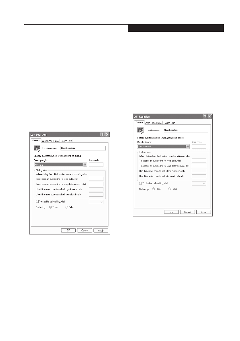
Note: Modem setting in Windows
XP
A. If you are located in Australia
1. Click Start select Control panel select
"Phone and Modem Options".
2. Double click New Location.
3. Choose "Australia" in Country/region pull
down menu bar.
4. Select Phone system as “Tone Dialing”.
5. Click OK and Apply.
B. If you are located in New Zealand
1. Click start select Control panel select
"Phone and Modem Options".
2. Double click New Location.
3. Choose "New Zealand" in Country/region
pull down menu bar.
4. Select Phone system as “Tone Dialing”.
5. Click OK and Apply.
Note:
The screens and illustrations shown in this
examples may slightly vary depending on the
operating environment that you have installed.
vii
Page 8

Fujitsu LifeBook® L Series
Table of Contents
NAMES OF THE PARTS
AND THEIR FUNCTIONS ............. 1
Front panel ...................................................1
Side panels .................................................. 3
Bottom panel ................................................6
Rear panel ................................................... 7
STATUS INDICATING LEDS ............. 9
Power Indicator ............................................ 9
Charging Status Indicator ............................ 9
Power Level Indicator ...................................9
Num Lock (Numerical Lock) Indicator ..........10
CD Access Indicator .................................... 10
Hard Disk Aaccess Indicator ........................10
Caps Lock Key .............................................10
Scroll Lock Indicator ..................................... 10
Incoming Mail Indicator ................................ 10
RUNNING THE COMPUTER
ON ITS BATTERY ......................... 11
Charging the battery .................................... 11
Running the computer on its battery ............ 11
Checking the power level of the battery ....... 12
Changing the internal battery pack .............. 14
POWER SOURCES ........................... 16
Connecting the power adapters ................... 16
Power On ..................................................... 17
Power Off ..................................................... 17
INSTALLING MEMORY ..................... 18
Preparing what are needed .......................... 18
Installing memory .........................................18
Checking the memory capacity ....................22
TROUBLESHOOTING....................... 23
Identifying the Problem ................................ 23
Specific Problems ........................................ 23
Troubleshooting Table ..................................24
NOTE:
A copy of LifeBook User's Manual is located on
your Microsoft Windows Desktop and Software
Drivers CD. You can use this LifeBook User's
Manual to find out more information about the
functions and features of your notebook.
viii
Page 9
4
7
6
5
NAMES OF THE PARTS
AND THEIR FUNCTIONS
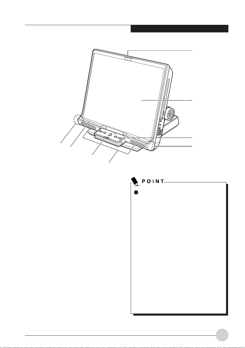
Front panel
1. Infrared/remote-control detector
Detects infrared rays from the wireless
keyboard and wireless mouse.
Do not touch this window when wireless
communications are held. Doing so could
cause degradation in communication
performance.
2. LCD (Liquid Crystal Display)
Information display device of your computer.
Getting to Know Your LifeBook
1
2
3
4
The phenomena described below are
due to the characteristics of LCD panels
and do not indicate that LCD panels are
defective.
About the characteristics of LCD
panels
• Your computer’s LCD was
manufactured through the use of high
technologies. For technical reasons,
your LCD might have picture elements
or dots that do not light up or those
that always stay on.
• Colors reproduced by LCD panels
vary to some extent from product to
product for reasons of manufacturing
processes. Also, a slight unevenness
of density may show up as a result of
changes in temperature.
Using the LCD dimmed for a long period
of time could shorten the life of its
backlight.
1
Page 10

3. One-touch buttons
Used to start applications or play music CDs.
4. Infrared remote-control detector
Detects infrared rays from the wireless
keyboard and wireless mouse.
Do not touch this window when wireless
communications are held. Doing so could
result in degradation in communication
performance.
5. Speakers
Sound output devices of your computer.
6. Keyboard lock
Allows you to lock and unlock the connection
between the computer and the wireless
keyboard.
7. Status indicating LEDs
Indicate the operating status of your
computer.
2
Page 11
Getting to Know Your LifeBook
1
2
3
4
6
7 8
5
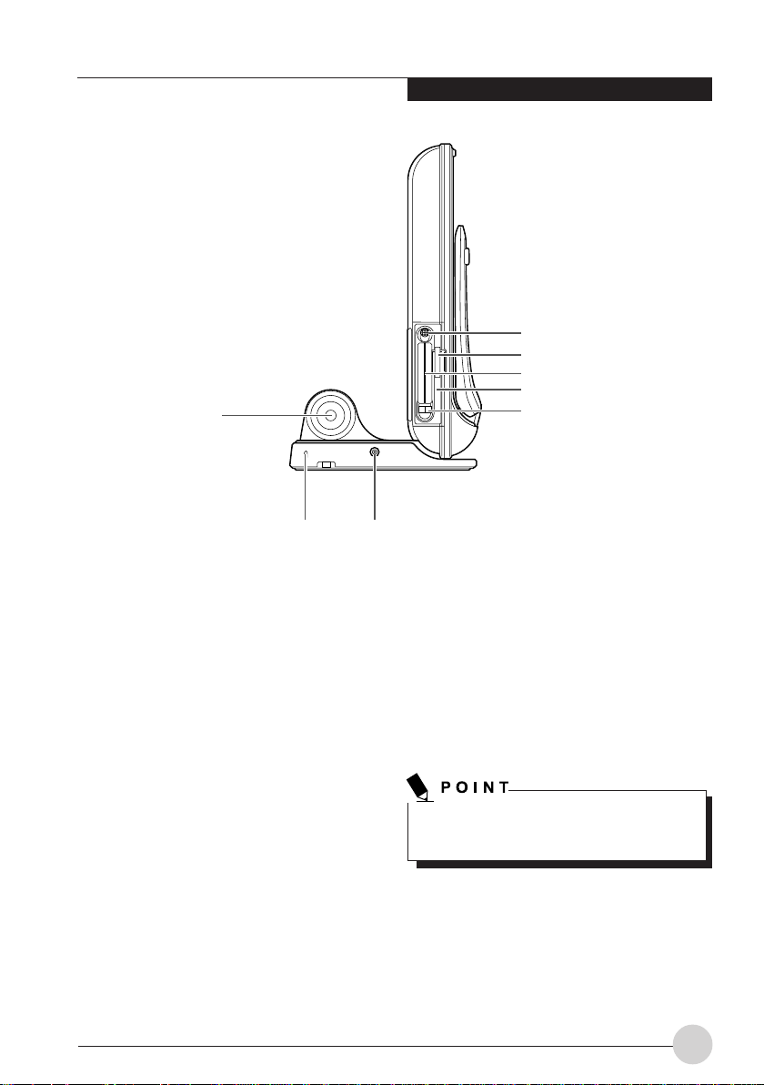
Side panels
Left panel of the computer
1. Power switch
Used to turn on the computer, to place it into
standby (hibernation) mode, and to resume
system operation. Slide the switch to the O
position to turn Off the computer, or to the
position to 1 turn it On.
2. SD/Memory stick port
Allows you to insert an optional memory card.
3. PC card slots
Allows you to insert optional PC cards. The
slot on the right side and the slot on the left
side are called slot 1 and slot 2, respectively.
4. Wireless switch
Used to turn On and Off the Wireless LAN
device.
5. PC card eject buttons
Used to eject the PC card.
6. Woofer
A Hi-Fidelity speaker that provides superb
audio performance.
7. Antitheft lock
Allows you to connect a commercially
available antitheft cable to your computer.
The antitheft lock is designed for
Kensington Microsaver Security System.
8. DC-IN jack
Used to connect the supplied AC adapter.
3
Page 12
1
2
3
4
7
5
6
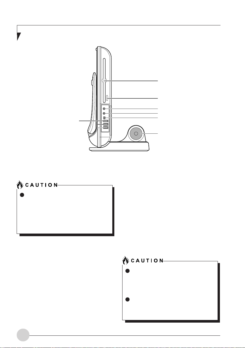
Right panel of the computer
Before connecting headphones or a
microphone to your computer, always
turn down your computer’s master
volume to a minimum.
Failure to do so could result in damage
to the audio unit connected or could
adversely affect your hearing.
1. CD/DVD drive
Your computer comes standard with a CDRW/DVD-ROM drive. The CD/DVD drive
allows you to read information from CD/DVDs
and play music CDs and DVD-Videos.
2. CD eject button
Press this button to insert a disk in the CD/
DVD drive or to eject it. This button is
operative only when the computer is turned
on.
4
3. Mic (microphone) jack
Allows you to connect a commercially
available monaural microphone with a Ø3.5
mini-plug.
This jack does not support some types of
microphones (e.g., dynamic microphone), so
you should consult a salesperson before
purchasing a microphone.
4. Headphone jack
Allows you to connect commercially available
headphones with a Ø3.5 mini-plug. This jack
is not compatible with some types of cable
connectors, so you should consult a
salesperson before purchasing headphones.
When you are listening to music with
headphones, be careful not to turn up
the volume excessively. Listening to very
loud sounds for a long time could
adversely affect your hearing.
When you are wearing headphones
connected to the computer, do not turn
or off the computer, or very loud sounds
could adversely affect your hearing.
Page 13

5. IEEE* 1394 (DV) port (*: pronounced “aitriple-ee”)
Allows you to connect a peripheral device,
such as a digital video camera (DVC), to the
computer through a DV cable.
6. Woofer
A Hi-Fidelity speaker that provides superb
audio performance.
7. USB port
Allows you to connect a peripheral device
compliant with USB standard.
Getting to Know Your LifeBook
5
Page 14
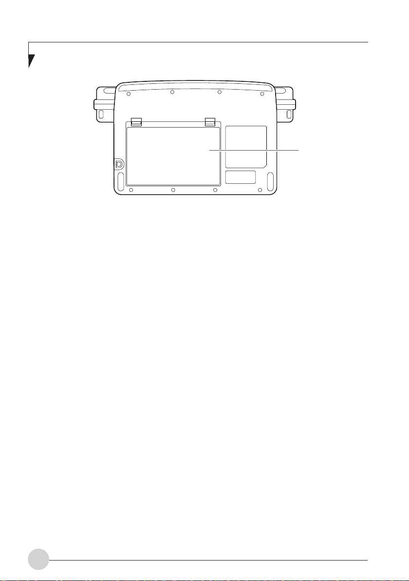
(Your computer or situation may not look exactly like this illustration.)
Bottom panel
1. Internal battery pack
An internal battery pack is installed here.
1
6
Page 15
2
3
4
5
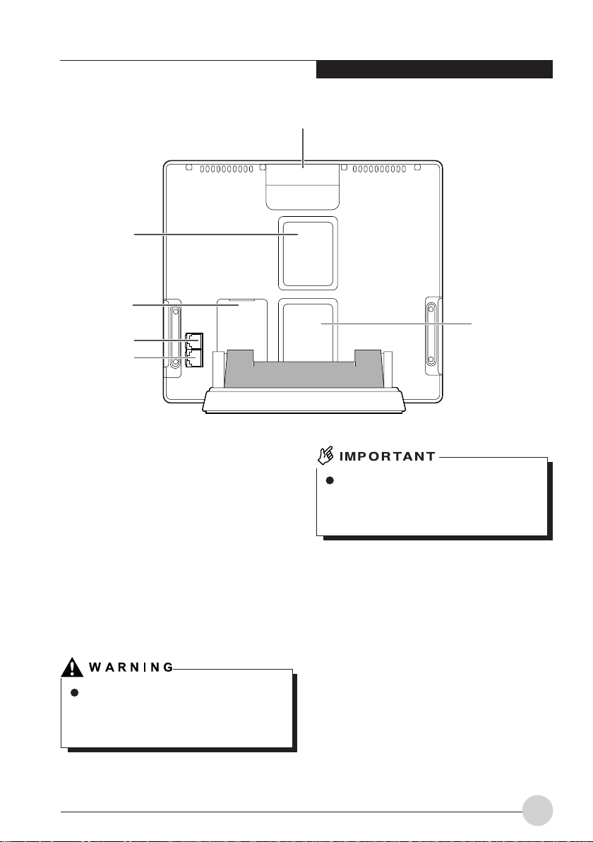
Rear panel
Getting to Know Your LifeBook
1
6
1. Handle
Used when carrying your computer.
2. Air outlet
Opening through which heat is forcibly
discharged from the computer. When you turn
on the computer, the cooling fan rotates for
a few seconds. When the temperature in the
computer rises high, the cooling fan
automatically starts to rotate to discharge
heat from the computer.
Do not obstruct the air outlet. Doing so
prevents heat from being discharged
from the computer and could result in
damage to your computer.
Do not put anything around the air outlet.
Objects placed around it, if any, may be
heated by heat discharged through the
air outlet.
3. Expansion RAM module slot
Used to install additional memory.
4. Modem port
Allows you to connect your computer to a
phone line through the supplied modular
cable for using an online service or browsing
the Internet.
5. LAN port
Allows you to connect your computer to a
LAN (local area network), using an optional
LAN cable.
7
Page 16
6. Air inlet
Opening through which the cooling fan takes
outside air into the computer.
Be careful not to obstruct the air inlet.
Doing so prevents heat from being
discharged from the computer and could
result in damage to your computer.
8
Page 17
Getting to Know Your LifeBook
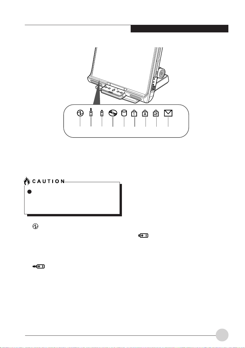
1 2 3 4 5 6 7 8 9
(Your computer or situation may not look exactly like this illustration.)
STATUS INDICATING LEDS
When your computer is turned off, no
indicators are displayed on the status
indicating LCD, except when the battery
pack is being charged.
1. Power Indicator
Indicates the operating status of the computer.
• Lit green: The computer is turned on.
• Blinks green: The computer is on standby.
• Not lit: The computer is turned off.
2. Charging Status
Indicator
When the AC adapter is connected to your
computer, this indicator lets you know whether
the battery pack is being charged.
• Lit green
Fully charged or not charged because no
battery pack is installed
• Lit orange
Being charged
• Blinks orange
Charging suspended (because a battery
temperature alarm was set off *)
• Not lit
Not charged because no AC adapter is
connected
*: If the internal battery becomes very hot or
cold for some reason, the battery protection
feature will be activated and set off a battery
temperature alarm to stop charging the
battery.
3. Power Level Indicator
Indicates the state of charge or remaining life of
the internal battery pack.
• Lit green
Between 51% and 100% charged*
• Lit orange
Between 50% and 13% charged*
• Lit red
Between 0% and 12% charged*
• Blinks orange
Measuring the remaining life of the internal
battery pack (4 seconds after being installed)
• Blinks red
Something is wrong with the battery.
• Not lit
No battery installed
9
Page 18
If you install the internal battery pack
when the computer is off, the power level
indicator will blink for a while, then
indicate the power level of the battery
pack for 5 seconds. Or it will turns off if
the battery pack is not charged.
If the AC adapter is not connected when
the internal battery pack is installed, the
power level indicator will not stay on but
blink at intervals of 6 seconds: ON for 1
second and OFF for 5 seconds.
4. CD Access Indicator
Lit when access is being made to the CD.
5. Hard Disk Aaccess
Indicator
Lit when access is being made to the hard disk.
Never press the power button when the hard
disk access indicator is lit. Doing so could
result in the corruption of data on the hard
disk.
7. A Caps Lock Key
Lit when the keyboard is placed in [Caps Lock]
mode.
To enter or exit [Caps Lock] mode, press the
[Caps Lock] key while holding down the [Shift]
key.
8. Scroll Lock Indicator
Lit when the window is locked so that it cannot
be scrolled up or down.
To enter or exit [Scroll Lock] mode, press the
[Num Lock] key while holding down the [Fn] key.
The reaction of the window depends on the
application used.
9. Incoming Mail Indicator
Blinks each time you get incoming e-mail if a onetouch button is so set up.
6. 1 Num Lock (Numerical
Lock) Indicator
Lit when the keyboard is placed in [Num Lock]
mode.
To enter or exit [Num Lock] mode, press the [Num
Lock] key.
10
Page 19
Getting to Know Your LifeBook
RUNNING THE COMPUTER
ON ITS BATTERY
Charging the battery
1. Connect the AC adapter to your computer.
2. The charging status indicator lights up.
It indicates whether the battery pack is being
charged.
3. When the charging status indicator turns
green, disconnect the AC adapter from
your computer.
Charge the supplied battery pack before
using it for the first time after purchase
or if it is not recharged for more than
one month.
To fully charge the battery pack,
continue charging until the charging
status indicator turns green.
When the battery pack is 90% or more
charged, it cannot be recharged even
when the AC adapter is connected. The
battery pack can be recharged when its
power level (or remaining battery life) is
89% or less.
The chargeability of the battery pack
decreases when it is charged in an very
hot or cold place.
When the battery pack is very hot, for
example, immediately after the use of
the computer, the battery protection
feature may be activated to prevent the
battery from being recharged. (If this
happens, the charging status indicator
blinks orange.) When the battery
temperature comes down, your
computer automatically restarts to
charge the battery pack.
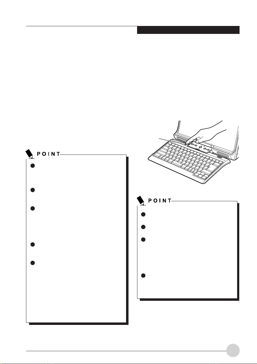
Running the computer on its
battery
This section explains how to run your computer
on its battery pack.
1. Disconnect the AC adapter from your
computer and press the power button to
start the computer.
Power button
Turn on the main power switch if it is in
the OFF position.
The operating time of the battery pack
shortens when it is used in a cold place.
The chargeability of the battery pack
decreases after it has been used over a
long period of time, and its operating
time shortens accordingly. If the battery
runs down soon, replace it with a new
battery.
A rise in the battery temperature may
slow down your computer. If this
happens, connect the AC adapter to
your computer.
11
Page 20
Checking the power level of
the battery
Battery temperature alarm
(charging status indicator)
When the computer is turned on or the battery is
being charged, the power level indicator lights
up or blinks to let you know the state of charge
of the internal battery pack.
The way the power level indicator
shows the power level
Lit when the computer is running or blinks
when the computer is on standby.
Lit/blinks green: Battery is between about
↓ 51% and 100% charged.
Lit/blinks orange: Battery is between about
↓ 13% and 50% charged.
Lit/blinks red: Low battery condition (about
12% or less charged) or dead
battery condition (0%
charged). When the battery
starts to run low (low battery
condition), your computer
sounds a low battery alarm
through the speakers.
For reasons of the characteristics of
lithium-ion batteries, the power level
indictor may not correctly indicate the
state of charge of the battery under
certain conditions (temperature
conditions, number of times the battery
has been discharged and recharged,
and so on).
When the battery is 90% or more
charged, it cannot be recharged even
when the AC adapter is connected to
your computer. The battery can be
recharged when its power level is 89%
or less.
If the battery pack becomes very hot or cold, the
charging status indicator will blink orange to tell
that the battery protection feature has been
activated and stopped charging the battery. When
the battery pack temperature returns to normal,
the charging status indicator stops blinking and
turns orange, and your computer automatically
restarts to charge the battery pack.
Battery failure alarm (power level
indicator)
If the battery pack cannot be charged normally,
the power level indicator will blink red.
If the power level indicator blinks red, turn
off the computer and remove and reinstall
the battery pack correctly. If the power level
indicator blinks red even though the battery
pack is installed correctly, it is in a defective
condition or at the end of its useful life. So
replace it with a new one.
12
Page 21
Getting to Know Your LifeBook
Low battery condition
When the battery is discharged to a very low
level, the power level indicator lights or blinks red.
If this happens, connect the AC adapter to your
computer immediately to recharge the battery.
The use of a weak battery may result in
the lost of the data you are currently
creating or saving. When the battery
starts to run low, connect the AC adapter
to your computer as soon as possible,
or if no AC adapter is available,
immediately save the data you are
creating, exit all programs and turn off
your computer.
Reading or writing data on the hard disk
requires a large amount of electric
power. Therefore, when the battery is
weak, connect the AC adapter to your
computer before reading or writing data
on the hard disk.
Leaving the battery weak for a specific
period of time causes the computer to
automatically go into standby mode.
When data is being read or written on
the hard disk, however, the computer
does not go into standby mode before
the reading or writing of data is
complete.
Your computer is configured by default
so that it will go into standby mode when
the power level reaches about 3%.
Precautions in using the battery
pack
The battery pack is shock-sensitive. To
avoid damage due to shock, be careful
not to drop the battery pack when
installing or removing it. For safety’s
sake, do not use any battery that has
been given a strong impact. The use of
a damaged battery could results in an
electric shock or explosion.
Do not take the battery apart
Taking the battery apart or touching its
internal components could result in an
electric shock or fire.
About the battery life
- Batteries are consumable and
gradually deteriorate with the
passage of time even when they are
not used. Therefore, to check the
condition of your battery pack, you
should run your computer on the
battery pack at least once a month.
- Leaving the battery pack in a hot
place for a long time accelerates the
deterioration of the battery.
- The battery pack is consumable and
its chargeability decreases gradually
as it is used. When the battery
reaches the end of its useful life,
replace it with a new one.
- The battery becomes exhausted in a
very short time when its useful life is
ending.
- When the battery reaches the end of
its useful life, remove it from the
computer. Leaving a dead battery in
the computer could cause shock
hazards or fire.
13
Page 22
About the disposal of the battery
pack
- Before disposing of the battery pack,
take necessary measures to prevent
it from shorting, for example, sealing
its connector with an insulating tape.
After removing the internal battery
pack, do not mix it with other types of
battery.
The internal battery pack (lithium-ion
battery) contains precious resources.
Therefore, you should dispose of the
disused battery pack as a recyclable
material if possible.
About the operating time
- The energy saving features of your
computer helps you conserve battery
power.
- Battery life greatly varies depending
on the ambient temperature. The life
of a battery may shorten when it is
used in a cold place.
You should power your computer
from the AC adapter when:
- Using an online service or navigating
the Internet.
- Using the hard disk or DVD/CD drive
frequently.
- Connecting to a LAN.
- Resetting the computer to the factory
defaults.
- Connecting two or more external
devices, such as PC cards and USB
devices, to your computer at the same
time.
Changing the internal battery
pack
Be sure to turn off your computer before
changing the internal battery pack. To
avoid shock hazards and fire, be careful
not to touch internal components of the
computer, including the battery
connector.
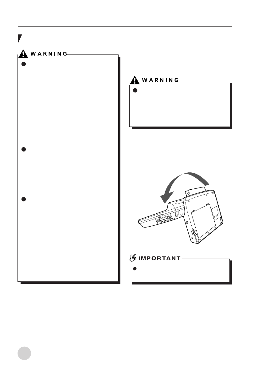
1. Turn off your computer.
2. Tip your computer with LCD facing
upward.
Tip your computer toward you carefully
so that it will not hit against anything.
14
Page 23
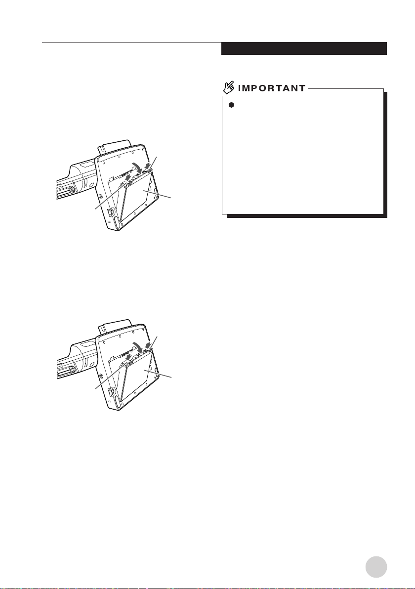
3. Remove the internal battery pack while
pressing the tabs in the direction of the
arrow.
The internal battery pack is detached from
the connector.
Ta b
Internal
battery
Ta b
pack
4. Install a new battery pack
Insert the new battery pack into the battery
housing with the slit in the battery pack
aligned with the projection on the computer,
and push in the battery pack until it clicks
into place.
Ta b
Getting to Know Your LifeBook
After removing the internal battery pack,
take necessary measures to prevent a
short circuit, for example, sealing its
connector with an insulating tape. After
removing the battery pack, do not mix it
with other types of battery.
The internal battery pack (lithium-ion
battery) contains precious resources.
Therefore, you should dispose of the
disused battery pack as a recyclable
material if possible.
Ta b
Internal
battery
pack
15
Page 24
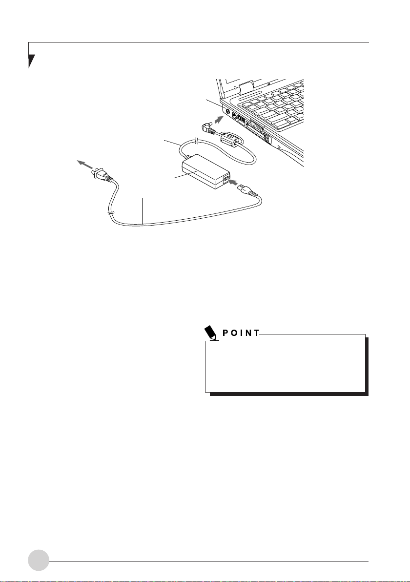
DC Power Jack
DC Output Cable
AC Adapter
AC Cable
POWER SOURCES
Your LifeBook notebook has two possible power
sources: a primary Lithium ion battery an AC
adapter.
Connecting the power
adapters
The AC adapter provides power for operating
your LifeBook notebook and charging the
batteries.
Connecting the AC adapter
1. Plug the DC output cable into the DC power
jack of your LifeBook notebook.
2. Plug the AC adapter into an AC electrical
outlet.
Switching from AC adapter power to battery
power
1. Be sure that you have at least one charged
battery installed.
2. Remove the AC adapter.
Your notebook will automatically switch from
DC power to battery power.
The Lithium ion battery is not charged at the
point of purchase. Remember to connect the
AC adapter to your notebook to charge the
battery fully before you use it for the first time.
16
Page 25
Power On
Power/Suspend/Resume button
The Power/Suspend/Resume button is used to
turn on your LifeBook notebook from its off state.
Once you have connected your AC adapter or
charged the internal Lithium ion battery, you can
power on your LifeBook notebook.
When you turn on your LifeBook notebook
be sure you have a power source. This means
that at least one battery is installed and
charged, or that the AC adapter is connected
and has power.
To turn on your LifeBook notebook from its off
state, press the Power/Suspend/Resume located
above the keyboard. When you are done working
you can either leave your LifeBook notebook in
Suspend mode, or you can turn it off.
Do not carry your LifeBook notebook around
with the power on or subject it to shocks or
vibration, as you risk damaging your
notebook.
When you power on your LifeBook notebook, it
will perform a Power On Self Test (POST) to check
the internal parts and configuration for correct
functionality. If a fault is found, your LifeBook
notebook will emit an audio warning and/or an
error message will be displayed. Depending on
the nature of the problem, you may be able to
continue by starting the operating system or by
entering the BIOS setup utility and revising the
settings.
Getting Started with your LifeBook
Notebook
Never turn off your LifeBook notebook during
the POST or it will cause an error message
to be displayed when you turn your LifeBook
notebook on the next time.
Power Off
Before turning off the power by choosing Shut
Down from Windows, check that the Hard Drive,
optical drive, PC Card and Floppy Disk Drive
Access indicators are all Off. If you turn off the
power while accessing a disk or PC Card there
is a risk of data loss. To ensure that your LifeBook
notebook shuts down without error, use the
Windows shut down procedure.
Never turn your LifeBook notebook off while
an application is running. Be sure to close all
files, exit all applications, and shut down your
operating system prior to turning off the
power. If files are open when you turn the
power off, you will lose any changes that have
not been saved, and may cause disk errors.
Using the correct procedure to shut down from
Windows, allows your LifeBook notebook to
complete its operations and turn off power in the
proper sequence to avoid errors.
The proper sequence is:
1. Click the Start button, and then click Shut
Down.
2. Select the Shut Down option from within the
Windows Shut Down dialog box.
3. Click OK to shut down your LifeBook
notebook.
After satisfactory completion of the POST, your
Life-Book notebook will load your operating
system.
If you are going to store your LifeBook notebook
for a month or more, see the Care and
Maintenance section of this manual.
17
Page 26
INSTALLING MEMORY
Here are the initial and maximum
memory capacities of your computer.
Initial memory capacity
Maximum memory capacity
256 MB 768 MB
Preparing what are needed
• Memory (expansion RAM module)
1 memory module can be installed.
Installing memory
When installing or removing memory, be
sure to turn off your computer and
disconnect the AC adapter to avoid
shock hazards.
Keep small objects, such as covers,
caps and screws, out of the reach of
babies and children to avoid the danger
of suffocation.
In the event a baby or child has
swallowed such an object, consult the
doctor immediately.
Memory is composed of static-sensitive
parts and it is easily broken by static
electricity built up in a human body.
Before handling memory, always touch
an appropriate metal object to discharge
static electricity from your body.
When installing or removing memory, be
sure to turn off your computer in
advance. If you install or remove memory
with the computer placed in standby or
hibernation mode, data could become
lost or the computer or memory could
be damaged.
To avoid damage, do not to touch
internal components unnecessarily.
To avoid damage, be careful not to drop
small parts into your computer.
1. Turn off the computer by sliding the main
power switch to the O position, and
disconnect the AC adaptor.
2. If the keyboard is detached, attach it.
3. Close the keyboard.
Fold the tilt feet flat.
Certain components around the memory
slots become very hot.
To avoid possible burns, do not install or
remove memory immediately after
turning off the computer but wait for its
internal components to cool down.
When installing or removing a memory
module, hold it by the edge so as not to
touch any contacts or IC. Also, be careful
not to touch internal components or
terminals of the computer. Touching
these parts with oily fingers could result
in a poor connection.
18
Page 27
User-Installable Features
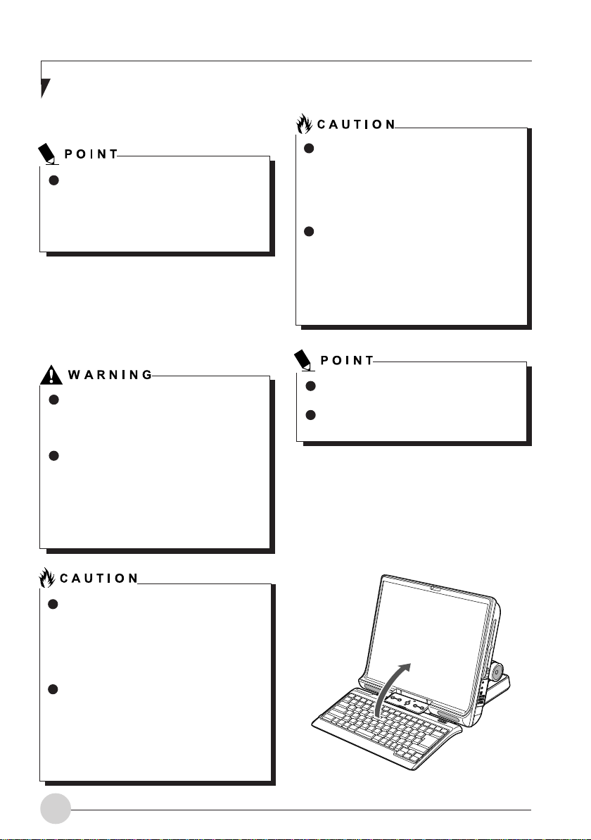
4. Raise the LCD panel.
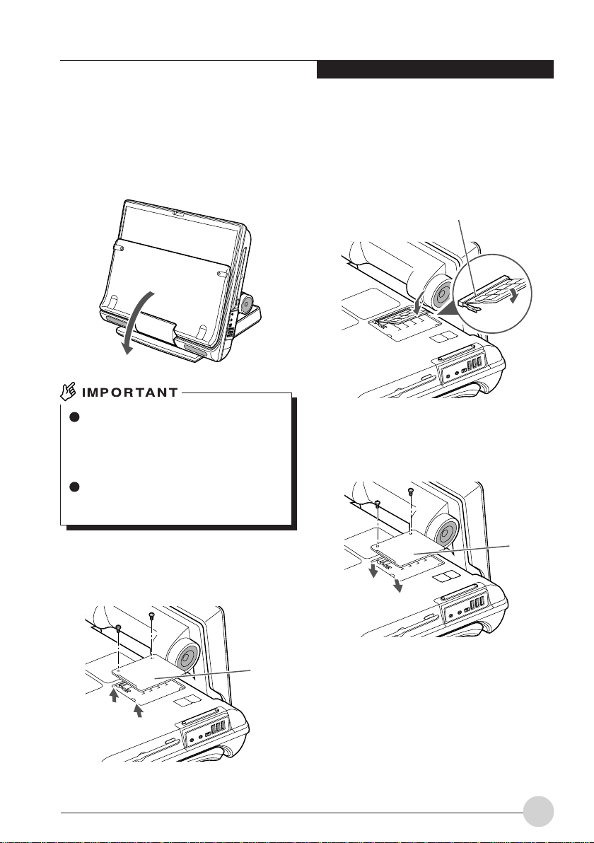
5. Tip your computer carefully toward you
and place it on its LCD panel, as shown
in the figure below.
When tipping your computer toward you,
do it on a flat desk or the like covered
with a soft cloth. Be careful that the LCD,
in particular, does not touch any object
with sharp edges or projections.
When tipping your computer toward you,
be especially careful not to give an
impact to it nor drop it.
7. Install memory.
Insert the memory diagonally into the slot
with the notch in the memory module aligned
with the projection on the connector, and
push the memory down until it clicks into
place.
Notch in the RAM module
8. Attach the expansion RAM module slot
cover and secure it with screws.
Attach the cover removed in step 6.
6. Remove the screws (2) shown in the
figure below, and detach the expansion
RAM module slot cover.
Cover
Cover
19
Page 28
Changing the memory
1. Turn off the computer by sliding the main
power switch to the O position, and
disconnect the AC adopter.
2. If the keyboard is detached, attach it.
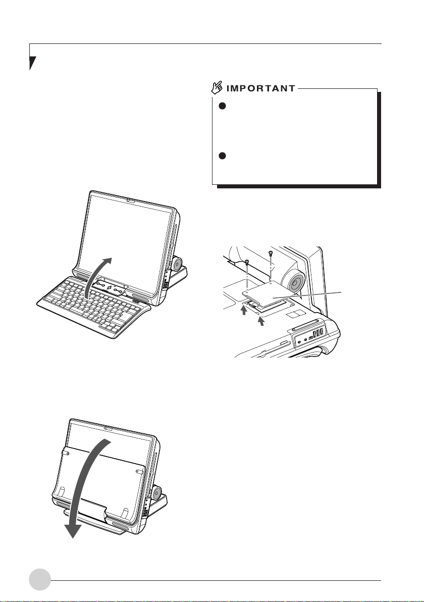
3. Close the keyboard.
Fold the tilt feet flat.
4. Raise the LCD panel.
When tipping your computer toward you,
do it on a flat desk or the like covered
with a soft cloth. Be careful that the LCD,
in particular, does not touch any object
with sharp edges or projections.
When tipping your computer toward you,
be especially careful not to give an
impact to it nor drop it.
6. Remove the screws (2) shown in the figure
below, and detach the expansion RAM
module slot cover.
Cover
5. Tip your computer carefully toward you
and place it on its LCD panel, as shown
in the figure below.
20
Page 29
User-Installable Features
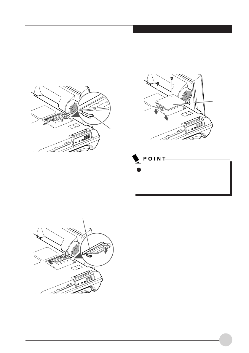
7. Remove the memory.
Undo the hooks on both sides that secure
the memory module. The memory raises
itself slightly. Then pull the memory
diagonally upward to remove it from the slot.
8. Install a new memory module.
Insert the memory diagonally into the slot
with the notch in the memory module aligned
with the projection on the connector, and
push the memory down until it clicks into
place.
Notch in the RAM module
9. Attach the expansion RAM module slot
cover and secure it with screws.
Attach the cover removed in step 6.
Cover
Ta b
After changing memory, check the
memory capacity of your computer to
be sure that the memory is installed
correctly.
21
Page 30
Checking the memory
capacity
If the memory is not installed correctly,
the error message “Expansion memory
error” or another message in English
may appear or nothing may be displayed
on your desktop when you turn on the
computer for the first time after installing
the memory. If such a case, press and
hold down the power button for 4
seconds or more to turn off your
computer, and remove and reinstall the
memory.
1. Turn on the computer.
2. Click the “Start” button and select
“Control Panel”.
The Control Panel window appears.
3. Click “Performance and Maintenance”,
and then “System”.
The “System Properties” dialog box appears.
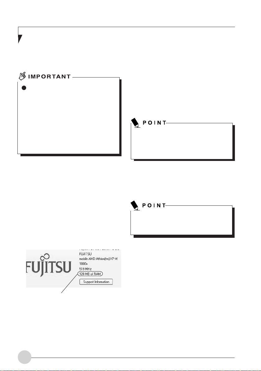
4. Check if the circled numerical value in the
figure below has increased by the size of
memory you added.
In this example, 256 MB of memory has been
installed a computer.
Your system uses 128 MB of memory as graphic
memory (can be adjusted from 16,32,64 and
128MB from BIOS), so that a memory capacity
128MB smaller than the actual memory capacity
is displayed in this window.
The memory capacity displayed may be further
1 MB less than the actual memory capacity,
depending on the system configuration.
You can change the graphic memory
(VRAM) size, using “UMA Video Memory
Size” in the “Advanced menu of BIOS
Setup”.
5. Click “OK”.
The “Performance and Maintenance” dialog
box appears again.
If the memory capacity displayed is not
correct, check if the memory is installed
properly.
Memory capacity
22
Page 31

Troubleshooting
TROUBLESHOOTING
Your LifeBook notebook is sturdy and subject to
few problems in the field. However, you may
encounter simple setup or operating problems
that you can solve on the spot, or problems with
peripheral devices that you can solve by replacing
the device. The information in this section helps
you isolate and resolve some of these
straightforward problems and identify failures that
require service.
Identifying the Problem
If you encounter a problem, go through the
following procedure before pursuing complex
troubleshooting:
1. Turn off your LifeBook notebook.
2. Make sure the AC adapter is plugged into
your LifeBook notebook and to an active AC
power source.
3. Make sure that any card installed in the PC
Card slot is seated properly. You can also
remove the card from the slot, thus
eliminating it as a possible cause of failure.
4. Make sure that any devices connected to the
external connectors are plugged in properly.
You can also disconnect such devices, thus
eliminating them as possible causes of failure.
5. Turn on your LifeBook notebook. Make sure
it has been off at least 10 seconds before
you turn it on.
6. Go through the boot sequence.
7. If the problem has not been resolved, refer
to the Troubleshooting Table that follows for
more detailed troubleshooting information.
8. If you have tried the solutions suggested in
the Troubleshooting Table without success,
contact your support representative.
Before you place the call, you should have the
following information ready so that the customer
support representative can provide you with the
fastest possible solution:
• Product name
• Product configuration number
• Product serial number
• Purchase date
• Conditions under which the problem occurred
• Any error messages that have occurred
• Hardware configuration
• Type of device connected, if any
See the Configuration Label on the bottom of your
LifeBook notebook for configuration and serial
numbers.
Specific Problems
Using the Troubleshooting Table
When you have problems with your LifeBook
notebook, try to find the symptoms under the
Problem column of the troubleshooting table for
the feature giving you difficulty. You will find a
description of common causes for that symptom
under the column Possible Cause and what, if
anything, you can do to correct the condition
under Possible Solutions. All possible causes or
solutions may not apply to your LifeBook
notebook.
If you keep notes about what you have
tried, your support representative may be
able to help you more quickly by giving
additional suggestions over the phone.
Do not return a failed LifeBook notebook
to your supplier until you have talked to a
support representative.
23
Page 32

Troubleshooting Table
Problem Possible Cause Possible Solution
Audio Problem
There is no sound
coming from the
bulit-in speakers
The software volume
control is set too low.
Adjust the sound volume control settings in
your software, operating system and
applications.
Headphones are plugged
into your LifeBook
notebook.
BIOS audio settings
are incorrect.
Software driver is not
configured correctly.
Optical Drive Problems
LifeBook notebook
fails to recognize
media discs.
The disc is not pushed
down onto raised center
circle of the drive.
Media player tray is not
latched shut.
Setup utility is set to
something other than
media player or Auto for
Secondary Master
Controller.
Wrong drive designator
was used for media player
in the application.
Plugging in headphones disables the built-in
speakers, remove the headphones.
Set the BIOS setup utility to the default values
within the Multimedia Device Configuration
menu.
Refer to your application and operating system
documentation for help.
Open media player tray and re-install the
media disc properly.
Push on the front of the media player tray until
it latches.
Revise BIOS settings for the Secondary
Master Controller.
Verify the drive designator used by the
application is the same as the one used by the
operating system.
When the operating system is booted from a
media player, drive designators are
automatically adjusted.
24
Windows Media Player
auto insert notification
function is disabled.
Media disc is dirty or
defective.
Start the media player from the desktop or
application software or re-enable the Windows
media player auto insert notification function.
Wipe the disc with a non-abrasive CD cleaning
cloth and reinsert. It if still will not work try
another media disc in the drive.
Page 33

Troubleshooting
Problem Possible Cause Possible Solution
Optical Drive Problems
The Media Player
Access indicator on
the Status Indicator
Panel blinks at
regular intervals
when no disc is in
the tray or the
media drive is not
installed.
The Windows media
player auto insert
notification function is
active and is checking to
see if a media disc is
ready to run.
This is normal.
The media player
will not play
international DVD
titles
The LifeBook
notebook fails to
Auto-Play a DVD
movie.
The region code for the
DVD does not match that
of the media player.
The media player software
has not been installed.
The notebook DVD players are set to play
DVD titles with region code number 3, which is
specified for the Asia market. The region
number is a regional restriction code defined
by the DVD Forum acting on the requirements
of Hollywood. Different region codes are
recorded on video DVD titles for publication in
different areas of the world. If the regional
code of the DVD player does not match the
regional codes on the titles, then playback is
impossible.
NOTE: You can change the region code on the
DVD player using the Properties menu of the
DVD soft-ware. Note, however, that you can
only change the region code up to four times.
After the fourth change, the last region code
entered becomes permanent, and cannot be
changed.
Locate and install the DVD-ROM Applications
CD.
25
Page 34

Problem Possible Cause Possible Solution
Floppy Disk Drive Problems
You cannot access
your floppy disk.
You tried to write to a write
protected floppy disk.
Eject the floppy disk and set it to write enable.
Hard Drive Problems
You cannot access
your hard drive.
Floppy disk is not loaded
correctly.
BIOS setup utility states
Floppy
Disk Controller:
Disabled.
Security is set to protect
access to floppy disk data.
The setup utility is
incorrectly set for your
internal (Primary Master)
or optional second hard
drive (Primary Slave).
The wrong drive
designator was used by
an application when a
bootable CD-ROM was
used to start the LifeBook
notebook.
Security is set so your
operating system cannot
be started without a
password.
Eject floppy disk, check orientation and reinsert.
Revise the setup utility Main menu settings to
enable Diskette Controller.
Verify your password and security settings.
Revise BIOS settings to set both Primary
Master and Primary Slave correctly.
Verify drive designator used by application is
in use by the operating system. When the
operating system is booted from a CD, drive
designations are automatically adjusted.
Verify your password and security settings.
26
Page 35

Troubleshooting
Problem Possible Cause Possible Solution
Keyboard or Mouse Problems
The built-in
keyboard does not
seem to work.
The LifeBook notebook
has gone into Suspend
mode.
Push the Power/Suspend/Resume button.
You have installed
an external
keyboard or
mouse, and it does
not seem to work.
You have
connected an
external keyboard
or a mouse and it
seems to be
locking up the
system.
Memory Problems
Your Info menu of
the BIOS setup
utility information,
does not show the
correct amount of
installed memory.
Your application has
locked out your keyboard.
Your external device is not
properly installed.
Your operating system
software is not set up with
the correct software driver
for that device.
Your operating system
software is not set up with
the correct software driver
for that device.
Your system has crashed.
Your memory upgrade
module is not properly
installed.
You have a memory
failure.
Try to use your integrated pointing device to
restart your system. If this fails, turn your
LifeBook notebook off press the Power/
Suspend/Resume button for 10 seconds or
more, and then turn it back on.
Re-install your device.
Check your device and operating system
documentation and activate the proper driver.
Check your device and operating system
documentation and activate the proper driver.
Try to restart your LifeBook notebook. If this
fails, turn your LifeBook notebook off press the
Power/ Suspend/Resume button for 10
seconds or more, and then turn it back on.
Remove and re-install your memory upgrade
module.
Check for Power On Self Test (POST)
messages.
Modem Problems
Messages about
modem operation.
Messages about modem
operation are generated
by whichever modem
application is in use.
See your application software documentation
for additional information.
27
Page 36

Problem Possible Cause Possible Solution
USB, Parallel, or IR Device Problems
You have installed
a USB, parallel, or
IR device. Your
LifeBook notebook
does not recognize
the device, or the
device does not
seem to work
properly.
The device is not properly
installed.
The device may have
been installed while an
application was running,
so your LifeBook is not
aware of its installation.
Your software may not
have the correct software
driver active.
Remove and re-install the device.
Close the application and restart your
LifeBook
notebook.
See your software documentation and activate
the correct driver.
PC Card Problems
A card inserted in
the PC Card slot
does not work or is
locking up the
system.
You may have the wrong I/
O address selected for
your device.
Your device and another
device are assigned the
same I/O address.
Parallel port is set to
output only.
The card is not properly
installed.
The card may have been
installed while an
application was running,
so your LifeBook
notebook is not aware of
its installation.
Your software may not
have the
correct software driver
active.
You may have the wrong I/
O address selected for
your PC Card device.
See your device documentation and software
docu mentation to determine the required I/O
address.
Change the settings in the BIOS setup utility.
Check all I/O addresses located within the
BIOS setup utility and any other installed
hardware or software to make sure there are
no duplications.
Check parallel port setting in the BIOS and set
to bi-directional or ECP.
Remove and re-install the card.
Close the application and restart your
LifeBook notebook.
See your software documentation and activate
the correct driver.
See your PC Card documentation to
determine the required I/O address. Change
the settings in the BIOS.
28
Page 37

Troubleshooting
Problem Possible Cause Possible Solution
PC Card Problems
A card inserted in
the PC Card slot
does not work or is
locking up the
system.
(continued)
Power Failures
Your PC Card device and
another device are
assigned the same I/O
address.
The card may have been
“removed” using the
Unplug or Eject Hardware
utility.
Check all I/O addresses located within the
BIOS setup utility and any other installed
hardware or software to make sure there are
no duplications.
If the Unplug or Eject Hardware utility has
been used to “remove” the PC card, the
system will not recognize the card, even if it is
still present in the slot. Physically remove the
card and reinstall it in the slot. If that is not
successful, reboot the system.
You turn on your
LifeBook notebook
and nothing seems
to happen.
The installed primary
battery is completely
discharged, there is no
optional second battery
installed or there is no
power adapter (AC
adapter) installed.
The primary battery is
installed but is faulty.
The battery or batteries
are low.
The power adapter (AC
adapter) is not plugged in
properly.
The power adapter (AC
adapter) has no power
from the AC outlet.
The power adapter (AC
adapter) is faulty.
Check the Status Indicator Panel to determine
the presence and condition of the batteries.
Install a charged battery or a power adapter.
Use the Status Indicator panel to verify the
presence and condition of the batteries. If a
battery is indicating a short, remove that
battery and operate from another power
source or replace that battery.
Check the Status Indicator Panel to determine
the presence and condition of the batteries.
Use a power adapter to operate until a battery
is charged or install a charged battery.
Verify that your adapter is connected correctly.
Move the AC cord to a different outlet, check
for a line switch or tripped circuit breaker for
the AC outlet.
Try a different power adapter or install a
charged optional second battery.
29
Page 38

Problem Possible Cause Possible Solution
Power Failures
Your LifeBook
notebook turns off
all by itself.
The power management
parameters are set for
auto timeouts which are
too short for your
operating needs.
Press any button on the keyboard, or move
the mouse to restore operation. If that fails,
push the Power/Suspend/Resume button.
Check your power management settings, or
close your applications and go to the Power
Options menu of the setup utility to adjust the
timeout values to better suit your operation
needs.
Your LifeBook
notebook will not
work on battery
alone.
The battery seems
to discharge too
quickly.
You are operating on
battery power only and
have ignored a low battery
alarm until the batteries
are all at the dead battery
state and your machine
has gone into Dead
Battery Suspend mode.
You have a battery failure.
Your power adapter has
failed or lost its power
source.
The installed battery is
dead.
No battery is installed.
The battery is improperly
installed.
Your installed battery is
faulty.
You are running an
application that uses a
great deal of power due to
frequent hard drive or
media player drive access,
use of a modem card or a
LAN PC card.
Install a power adapter or a charged battery,
then push the Power/Suspend/Resume button.
Verify the condition of the batteries using the
Status Indicator Panel, and replace or remove
any batteries that are shorted.
Make sure the adapter is plugged in and the
outlet has power.
Replace the battery with a charged one or
install a power adapter.
Install a charged battery.
Verify that the battery is properly connected by
re-installing it.
Verify the condition of the battery using the
Status Indicator panel and replace or remove
any battery that is shorted.
Use both the primary battery and/or use a
power adapter for this application when at all
possible.
30
Page 39

Troubleshooting
Problem Possible Cause Possible Solution
Power Failures
The battery seems
to discharge too
quickly.
The power savings
features may be disabled.
Check the power management and/or setup
utility settings in the Power Options menu and
adjust according to your operating needs.
(continued)
Shutdown and Startup Problems
The Power/
Suspend/ Resume
button does not
work.
The system
powers up and
displays power-on
information, but
fails to load the
operating system.
The brightness is turned
all the way up.
The battery is very old.
The battery has been
exposed to high
temperatures.
The battery is too hot or
too cold.
The Power/Suspend/
Resume button is disabled
from the Advanced
submenu of the Power
menu of the setup utility.
You did not hold the
button in long enough.
There may be a conflict
with the application
software.
The boot sequence
settings of the setup utility
are not compatible with
your configuration.
You have a secured
system requiring a
password to load your
operating system.
Turn down the brightness adjustment. The
higher the brightness the more power your
display uses.
Replace the battery.
Replace the battery.
Restore the LifeBook to normal operating
temperature. The Battery Charging icon on the
indicator panel will flash when the battery is
outside operating range.
Enable the button from the setup utility.
Hold the button longer. This may need to be a
few seconds if your application is preventing
the CPU from checking for button pushes.
Close all applications and try the button again.
Set the operating source by pressing the
[ESC] key while the Fujitsu logo is on screen
or use the [F2] key and enter the setup utility
and adjust the source settings from the Boot
menu.
Make sure you have the right password. Enter
the setup utility and verify the Security settings
and modify them as accordingly.
31
Page 40

Problem Possible Cause Possible Solution
Shutdown and Startup Problems
The system
powers up and
displays power-on
information, but
fails to load the
operating system.
(continued)
Internal hard drive was
not detected.
Use the BIOS setup utility or Primary Master
submenu, located within the Main menu, to try
to auto detect the internal hard drive.
An error message
is displayed during
the LifeBook
notebook (boot)
sequence.
Your LifeBook
notebook appears
to change setup
parameters when
you start it.
Video Problems
Display is blank
when you turn on
the system.
Power On Self Test
(POST) has detected a
problem.
BIOS setup changes were
not saved when you made
them and exited the BIOS
setup utility returning it to
previous settings.
The BIOS CMOS hold-up
battery has failed.
Something is pushing on
the Closed Cover switch.
The LifeBook notebook is
set for an external monitor
only.
The angle and brightness
settings of the display are
not adequate for the
lighting conditions.
See Power On Self Test (POST) messages to
determine the meaning of the problem. Not all
messages are errors; some are status
indicators.
Make sure you select Save Changes And Exit
when exiting the BIOS setup utility.
Contact your support representative for
repairs.
This is not a user serviceable part but has a
normal life of 3 to 5 years.
Clear the Closed Cover switch.
Pressing [F10] while holding down the [Fn] key
allows you to change the destination of your
display video. Each time you press the
combination of keys you will step to the next
choice. The choices, in order, are: built-in
display only, external monitor only, both built-in
display and external monitor.
Move the display and the brightness control
until you have adequate visibility.
32
Page 41

Troubleshooting
Problem Possible Cause Possible Solution
Video Problems
Display is blank
when you turn on
the system.
(continued)
The power management
timeouts may be set for
very short intervals and
you failed to notice the
display come on and go
off again.
Press any button on the keyboard, or move
the mouse to restore operation. If that fails,
push the Power/Suspend/Resume button.
(The display may be shut off by Standy mode,
Auto Suspend or Video Timeout)
When the ATI
Driver CD is first
installed, you
receive a Microsoft
message informing
you that the ATI
driver is not
compatible with
your operating
system.
The LifeBook
notebook turned
on with a series
of beeps and your
built-in display is
blank.
The display goes
blank by itself after
you have been
using it.
The warning does not
apply to your LifeBook; the
driver has been
thoroughly tested and its
installation will not
jeopardize the
performance of your
system.
Power On Self Test
(POST) has detected a
failure which does not
allow the display to
operate.
The LifeBook notebook
has gone into Video
timeout, Standby mode,
Suspend mode or
Hibernation (Save-to-Disk)
mode because you have
not used it for a period of
time.
Something is pushing on
the Closed Cover switch.
The power management
timeouts may be set for
very short intervals and
you failed to notice the
display come on and go
off again.
If this message appears on your screen, click
the Continue Anyway or Yes buttons to
proceed.
Contact your support representative.
Press any button on the keyboard, or move
the mouse to restore operation. If that fails,
push the Power/Suspend/Resume button.
Check your power management settings, or
close your applications and go to the Power
Savings menu of the setup utility to adjust the
timeout values to suit your operation needs.
Check the Closed Cover switch.
Press any button on the keyboard, or move
the mouse to restore operation. If that fails,
push the Power/ Suspend/Resume button.
(The display may be shut off by Standby
Mode, Auto Suspend or Video Timeout)
33
Page 42

Problem Possible Cause Possible Solution
Video Problems
The built-in display
does not close.
A foreign object, such as a
paper clip, is stuck
between the display and
the keyboard.
Remove all foreign objects from the keyboard.
The built-in display
has bright or dark
spots.
The application
display uses only a
portion of your
screen and is
surrounded by a
dark frame.
The Display is dark
when on battery
power.
You have
connected an
external monitor
and it does not
display any
information.
If the spots are very tiny
and few in number, this is
normal for a large LCD
display.
If the spots are numerous
or large enough to
interfere with your
operation needs.
You are running an
application that does not
support 800 x 600/1024 x
768 pixel resolution
display and display
compression is enabled.
The BatteryAid default is
set on low brightness to
conserve power.
Your BIOS setup is not set
to enable your external
monitor.
Your external monitor is
not properly installed.
This is normal; do nothing.
Display is faulty; contact your support
representative.
Display compression gives a clearer but
smaller display for applications that do not
support 800 x 600 /1024 x 768 pixel
resolution. You can fill the screen but have less
resolution by changing your display
compression setting, (See the Video Features
submenu, located within the Advanced menu
of the BIOS.)
Press [Fn] + [F7] to increase brightness or
double-click on BatteryAid gauge and adjust
Power Control under battery settings.
Toggle the video destination by pressing [Fn]
and [F10] together, or check your BIOS setup
and enable your external monitor. (See Video
Features submenu, located within the
Advanced Menu of the BIOS.)
Reinstall your device.
You have
connected an
external monitor
and it does not
come on.
34
Your operating system
software is not set up with
the correct soft-ware
driver for that device.
Your external monitor is
not compatible with your
LifeBook notebook.
Check your device and operating system
documentation and activate the proper driver.
See your monitor documentation and the
External Monitor Support portions of the
Specifications section.
Page 43

Troubleshooting
Problem Possible Cause Possible Solution
Video Problems
The Properties
section of the Intel
Graphics
Technology
window displays
an incorrect
amount of Video
RAM present.
Miscellaneous Problems
This is not a problem; it is
a result of UMA
technology.
The Intel graphics chipset uses Unified
Memory Architecture (UMA) which allows the
video chipset to share up to 128 MB of the
system’s main memory.
The amount being used will vary with the
system needs, and the amount of video RAM
indicated will vary as well.
An error message
is displayed on the
screen during the
operation of an
application.
Application software often
has its own set of error
message displays.
See your application manual and help displays
screens for more information. Not all
messages are errors some may simply be
status.
35
Page 44

版權
版權
富士通有限公司會盡力保証本文檔內容的準確性
和完整性。但是﹐由于我們仍在不斷改進產品的
功能﹐因此不能確保本文檔沒有任何差錯。對于
文檔中錯誤﹑疏忽或以后的修改我們不承擔任何
責任
。
LifeBook 是富士通有限公司的商標
Microsoft﹑Windows﹑MS﹑MS-DOS 和 Windows NT
是 Microsoft Corporation 在美國和其它國家或地區
的註冊商標
Phoenix 是 Phoenix Technologies Corporation 在美國
的註冊商標
版權所有© 1981-1999 Microsoft Corporation﹐保留
所有權利
版權所有© 1999 Phoenix Technologies, Ltd﹐保留所
有權利
。
。
。
。
。
其它所有產品是其各自公司的商標或註冊商標
©版權所有 2003 Fujitsu Limited﹐保留所有權利
未經富士通有限公司事先書面同意﹐嚴禁拷貝﹑
複製或翻譯本出版物中的任何內容。未經富士通
有限公司書面同意﹐嚴禁以任何電子形式存儲或
傳輸本出版物中的任何內容
操作使用應符合以下兩項條件:
(1) 本設備不能造成有害干擾﹐
(2) 本設備必須能承受接收到的干擾﹐包括會造
成意外操作的干擾
網站: www.pc-ap.fujitsu.com
。
。
。
。
一致性聲明
根據 FCC 第 15 部分內容
本設備遵循 FCC 規則的第 15 部分。設備操作必須符合下列兩項條件:
(1)本設備不準造成有害的干擾。(2)本設備必須接受任何接收到的干擾﹐包括會造成意外操作的干擾
。
i
Page 45

重要安全說明
1. 請仔細閱讀這些說明﹐并保存起來以備以后
參考
。
2. 遵循本產品上標示的所有警告和指示
3. 清潔之前先從牆上插座拔下本產品的電源
線。切勿使用液體或噴霧清潔劑。使用濕布
進行清潔
4. 不要在靠近水的地方使用本產品
5. 不要將本產品放在不穩定的車輛﹑支架或桌
子上。以免產品跌落﹐造成嚴重損壞
6. 機殼上﹑背部和底部的槽口用于通風目的
為確保本產品的可靠運行﹐不至于出現過熱
高溫﹐嚴禁堵塞和蓋住這些槽口。嚴禁將本
產品放在床﹑沙發﹑地毯或其它類似表面
上﹐從而造成這些槽口的堵塞。切勿將本產
品靠近散熱器或電熱器﹐或放在它們的上
面﹐也不要將本產品放在箱內﹐除非通風條
件良好
7. 只能按照標簽上註明的電源類型使用本產
品。如果您不確定可用的電源類型﹐請咨詢
經銷商或當地的電力公司
8. 本產品配備了一個 3 線接地型插頭,這是一
種有第三(接地)腳的插頭。此插頭只能插
入接地型的插座。這是一種安全功能。如果
您無法將插頭插入插座,請聯繫電工更換過
時的插座。請勿破壞接地型插頭的功能
。
。
。
。
。
。
。
。
9. 不要將任何物品壓在電源線上。本產品的電
源線不應位于人們經常出入的地方
10. 如果使用本產品需要延長電線﹐一定要確保
接入延長電線上設備的額定安培總數不超過
延長線的額定安培數。也要確保接入牆上插
座上所有產品的總額定值不會超過 15 安培
11. 嚴禁將任何物品通過機殼的槽口插入到本產
品﹐這樣可能會碰到高壓部件﹐造成火災或
電擊。切勿將任何液體洒到本產品上
12. 不要嘗試自行維修本產品﹐打開或卸下護蓋
可能會使您遭到電擊﹐或其它危險。請務必
請專業的維修人員進行維修
13. 如果出現以下情況﹐應從牆上插座拔下本產
品的電源線﹐請專業的維修人員進行維修:
a. 電源線或插頭損壞或磨損
b. 產品內濺入了液體
c. 產品遭到雨淋或進水
d. 正常操作情況下﹐產品運行不正常。只調整
操作說明中介紹過的那些控制﹐因為不正確
地調整其它控制可能會造成損壞﹐通常需要
合格的技術人員花費更大的精力維修產品
e. 產品跌落﹐或機殼損壞
f. 產品性能出現明顯變化﹐需要進行維修
。
。
。
。
。
。
。
。
。
。
ii
Page 46

14. 注意。更換電池時一定要確保電池裝入的極
性位置正確。更換的電池類型不正確或處理
不當﹐會有爆炸的危險。切勿對電池充電﹑
折解或投入火中。只應使用製造商建議的相
同或同類電池更換。并按照製造商的說明處
理用過的電池
15. 只使用專供本裝置使用的正確類型的電源線
組(附件箱中提供)。它應是可分開的類
型: UL 認証∕CSA 認証﹐BS1363﹑ASTA﹑
SS145 認証﹐額定 10A 250V 最小﹐VDE 認
証或等同。最大長度為 15 英尺(4.6 米)
。
。
iii
Page 47

要求高安全性的應用
本產品系為一般應用領域設計﹑開發和製造﹐包
括但不限于一般辦公使用﹑個人使用﹑家庭使用
和普通行業使用﹐如果沒有極高的安全保障﹐則
本產品不適用于伴隨有嚴重風險或危險﹐可能會
直接導致死亡﹑人身傷害﹑嚴重物理損壞或其它
損失的應用(簡稱“要求高安全性的應用”)﹐
包括但不限于核設施中的核能反應核心控制﹑航
空自動導航﹑空中管制﹑大型運輸控制系統的運
行控制﹑用于生命維持系統的醫療儀器﹐以及武
器系統中的導彈發射控制。如果不能完全滿足
“要求高安全性的應用”要求﹐則嚴禁使用本產
品
。
數據存儲介質與客戶責任
對計算機(如硬盤)中所存儲數據唯一有效的保
護方法是購買者定期備份數據。富士通及其附屬
機構﹑供應商﹑服務提供商﹑零售商對于退回給
富士通或其服務提供商進行保修服務或做其它修
理的任何媒體上或產品任何部分上存儲或使用的
所有軟件程序﹑數據或其它信息﹐包括但不限于
恢復這些程序﹑數據或其它信息的費用﹐不承擔
任何責任。在退回給富士通或指定維護中心進行
保修服務或做其它修理時﹐對所有存儲媒體或產
品任何部分上存儲的所有軟件程序﹑數據或信息
進行備份是購買者的責任
。
iv
Page 48

Fujitsu LifeBook® L 系列
目錄
目錄
部件名稱及其功能 .............................. 1
前面板 .................................................................... 1
側面板 .................................................................... 3
底板 ........................................................................ 6
后面板 .................................................................... 7
狀態指示燈 ......................................... 9
電源指示燈 ............................................................ 9
充電狀態指示燈 ................................................... 9
電池電量指示燈 ................................................... 9
Num Lock(數字鍵鎖定)指示燈 ..................... 10
CD 訪問指示燈 ..................................................... 10
硬盤訪問指示燈 ................................................... 10
Caps Lock 指示燈 .................................................. 10
Scroll Lock 指示燈 ................................................ 10
郵件進入指示燈 ................................................... 10
靠電池運行計算機 .............................. 11
給電池充電 ............................................................ 11
靠電池運行計算機 ............................................... 11
檢查電池電量 ....................................................... 12
更換內部電池組 ................................................... 14
電源 .................................................... 16
連接電源適配器 ................................................... 16
開機 ........................................................................ 17
關機 ........................................................................ 17
安裝內存 ............................................. 18
准備工作 ................................................................ 18
安裝內存 ................................................................ 18
檢查內存容量 ....................................................... 22
疑難解答 ............................................. 23
識別問題 ................................................................ 23
具體問題 ................................................................ 23
疑難解答表 ............................................................ 24
註:
LifeBook 用戶說明書位于微軟 Windows 桌面和軟件
驅動程序光盤上。您可以使用此 LifeBook 用戶說明
書找到您的筆記型計算機的各種功能和特點的更詳
細信息
。
v
Page 49

了解您的 LifeBook
1
2
3
4
7
6
5
4
部件名稱及其功能
前面板
1. 紅外線∕遙控探測器
探測來自無線鍵盤和無線鼠標的紅外線信
號
。
當保持無線通訊時不要觸摸此窗口。否則會
造成通訊性能下降
2. LCD(液晶顯示屏)
計算機的信息顯示設備
。
。
要點
以下所描述的現象是由于 LCD 面板的特
點所致﹐并不表示 LCD 面板有缺陷
關于 LCD 面板特點
• 您計算機的 LCD 是採用高科技技術製
造而成。由于技術上的原因﹐您的
LCD 可能會有一些像素或一些點不亮
或始終發亮
• 由于生產過程的原因﹐各產品之間
LCD 面板再現的色彩會有一定程度的
不同。另外﹐由于溫度的變化也可能
造成輕微的色彩濃度顯示的不均勻
長時間使用顏色昏暗的 LCD 會縮短其背
景照明的使用壽命
。
。
。
。
1
Page 50

3. 單觸式按鈕
用于啟動應用程序或播放音樂 CD
4. 紅外線遙控探測器
探測來自無線鍵盤和無線鼠標的紅外線信
號
。
當保持無線通訊時不要觸摸此窗口。否則會
造成通訊性能下降
5. 揚聲器
計算機的聲音輸出設備
6. 鍵盤鎖
用于鎖住和打開計算機與無線鍵盤之間的連
接
。
7. 狀態指示 LED
指示計算機的運行狀態
。
。
。
。
2
Page 51

了解您的 LifeBook
1
2
3
4
6
7 8
5
側面板
計算機的左面板
1. 電源開關
用于開啟計算機﹐進入待機(睡眠)模式﹐
以及恢復系統操作。將開關滑動到 O 位置即
可關閉計算機﹐或滑動到 1 位置開啟計算
機
。
2. SD∕記憶棒端口
用于插入選購件儲存卡
3. PC 卡插槽
用于插入選購件 PC 卡。分別將右側和左側的
插槽稱為插槽 1 和插槽 2
4. 無線開關
用于開啟和關閉無線 LAN 設備
。
。
。
5. PC 卡彈出按鈕
用于彈出 PC 卡
6. 低音揚聲器
可提供完美聲音性能的高保真度揚聲器
7. 防盜鎖
用于將市場上購買的防盜電纜連接到計算
機
。
要點
此防盜鎖是專為 Kensington Microsaver Security
System 而設計
8. 直流輸入插孔
用于連接隨機提供的交流適配器
。
。
。
。
3
Page 52

1
注意
2
3
4
7
5
6
計算機的右面板
注意
將耳機或麥克風連接到計算機之前﹐應
始終先將計算機的主音量調低到最小
否則會損壞所連接的音頻裝置或對您的
聽力造成有害的影響
。
1. CD/DVD 驅動器
本計算機將 CD-RW/DVD-ROM 驅動器作為標
準配置。此 CD/DVD 驅動器可用于讀取 CD/
DVD 信息﹐以及用于播放 CD 和 DVD 彔像
2. CD 彈出按鈕
按此按鈕可將光碟插入 CD/DVD 驅動器或彈
出光碟。此按鈕只有在計算機開啟時才可操
作
。
4
3. Mic(麥克風)插孔
用于連接市場上可購買的 ø3.5 迷你插頭單聲
道麥克風
此插孔不支持某些類型的麥克風(例如﹐動
。
態麥克風)﹐因此在您購買麥克風之前﹐請
。
咨詢銷售人員
。
4. 耳機插孔
用于連接市場上可購買的 ø3.5 迷你插頭耳
機。此插孔與某些類型電纜連接器不兼容﹐
因此在購買耳機之前﹐請咨詢銷售人員
。
當您用耳機聽音樂時﹐請小心不要將音
。
量調得過高。長時間聽非常響的聲音會
對您的聽力造成有害的影響
當您戴著與計算機連接的耳機時切勿關
。
閉計算機﹐否則很響的聲音會對您的聽
力造成有害的影響
。
Page 53

5. IEEE*1394(DV)端口(*:發音“ai-triple-
ee”)
用于通過 DV 電纜將外部設備﹐如數碼攝像
機(DVC)連接到計算機
6. 低音揚聲器
可提供完美聲音性能的高保真度揚聲器
7. USB 端口
用于連接符合 USB 標準的外部設備
。
。
。
了解您的 LifeBook
5
Page 54

底板
1. 內部電池組
內部電池組安裝在這里
1
(您的計算機或狀況可能與此圖看上去不完全一致。)
。
6
Page 55

了解您的 LifeBook
1
2
3
6
4
5
后面板
1. 把手
搬動計算機時使用
2. 出風口
計算機中的熱量通過此開孔被強制排出。打
開計算機時﹐冷卻風扇會旋轉幾秒鐘。當計
算機內部溫度升高時﹐冷卻風扇會自動開始
旋轉散發計算機內的熱量
警告
切勿堵塞出風口。否則會阻礙計算機內
的熱量散發﹐從而造成計算機損壞
。
。
重要
切勿在出風口周圍放置任何物品。如果
周圍放有物體的話﹐則可能被出風口排
出的熱量加熱
3. 擴展 RAM 模塊插槽
用于安裝附加內存
4. 調制解調器端口
用于將計算機通過隨機提供的組合電纜連接
到電話線﹐以使用在線服務或瀏覽因特網
5. LAN 端口
。
使用選購件 LAN 電纜﹐將計算機連接到 LAN
(本地网絡)
。
。
。
。
7
Page 56

6. 進風口
冷卻風扇通過此開孔將外面的空氣吸入計算
機
。
注意
注意不要堵塞進風口。否則會阻礙計算
機內的熱量散發﹐從而造成計算機損
壞
。
8
Page 57

了解您的 LifeBook
1 2 3 4 5 6 7 8 9
(您的計算機或狀況可能與此圖看上去不完全一致。)
狀態指示燈
注意
計算機關閉時﹐除非電池正在充電﹐否
則狀態指示 LCD 上沒有指示顯示
1. 電源指示燈
表示計算機的運行狀態
• 綠色點亮:計算機開啟
• 綠色閃爍:計算機待機
• 不亮:計算機關閉
。
。
。
。
2. 充電狀態指示燈
當交流適配器連接到計算機時﹐此指示燈可讓您
知道電池組是否正在充電
• 綠色點亮
已經完全充電﹐或由于未裝入電池組而未充
電
。
• 橙色點亮
正在充電
。
。
。
• 橙色閃爍
充電暫停(由于發出了電池溫度警告*)
• 不亮
由于未連接交流適配器而沒有充電
※:如果由于某些原因導致內部電池變得很熱或
很冷﹐則電池保護功能將被啟動﹐并發出電
池溫度警告﹐以停止電池充電。
。
。
3. 電池電量指示燈
表示內部電池組的充電狀態或剩餘電量狀態
• 綠色點亮
電池充電量在 51% 和 100% 之間*
• 橙色點亮
電池充電量在 13% 和 50% 之間*
• 紅色點亮
電池充電量在 0% 和 12% 之間*
• 橙色閃爍
測定內部電池組的剩餘電量(電池裝入后 4 秒
鐘)
。
• 紅色閃爍
電池有一些問題
• 不亮
未裝入電池
。
。
。
。
。
。
9
Page 58

注意
如果在計算機關閉時安裝內部電池組﹐
則電池電量指示燈將閃爍片刻﹐然后再
指示電池電量 5 秒鐘。而如果電池組未
充電﹐則指示燈將熄滅
如果裝入內部電池組時未連接交流適配
器﹐則電池電量指示燈將不保持點亮﹐
但以 6 秒鐘為間隔閃爍:開 1 秒鐘﹐關
5 秒鐘
。
4.
CD 訪問指示燈
當正在訪問 CD 時點亮
。
。
5. 硬盤訪問指示燈
當正在訪問硬盤時點亮
要點
在硬盤指示燈點亮時決不能按電源按鈕。否
則會導致硬盤中的數據破壞
。
。
6. 1 Num Lock(數字鍵鎖定)
指示燈
當鍵盤處于 [Num Lock] 模式時點亮
若要進入或退出 [Num Lock] 模式﹐按 [Num Lock]
鍵
。
。
7. A Caps Lock 指示燈
當鍵盤處于 [Caps Lock] 模式時點亮
若要進入或退出 [Caps Lock] 模式﹐則按住 [Shift]
鍵的同時按 [Caps Lock] 鍵
8.
Scroll Lock 指示燈
將視窗鎖住﹐使其無法上下滾動時點亮
若要進入或退出 [Scroll Lock] 模式﹐則按住 [Fn] 鍵
的同時按 [Num Lock] 鍵。視窗的反應視所使用的
應用程序而定
。
。
。
。
9. 郵件進入指示燈
如果如此設定了一個單觸按鈕﹐則每次收到電子
郵件將閃爍
。
10
Page 59

了解您的 LifeBook
靠電池運行計算機
給電池充電
1. 將交流適配器連接至計算機
2. 充電狀態指示燈點亮
表示電池組是否正在充電
3. 當充電狀態指示燈變為綠色時﹐請從計算機
上斷開交流適配器的連接
要點
購買后第一次使用隨機提供的電池組之
前﹐或者電池超過一個月未充電時請對
電池充電
若要對電池組完全充電﹐請連續充電﹐
直至充電狀態指示燈變為綠色。
當電池已充電 90% 或更高時﹐則即使還
連接著交流適配器﹐它也不能再充電
當電量(或剩餘電池使用時間)為 89%
或更少時﹐電池組才會充電
如果在超高溫或超低溫情況下對電池充
電﹐則電池組的可充電性會降低
例如﹐在用過計算機后﹐如果電池溫度
太高﹐電池保護功能會立即啟動﹐防止
再對電池充電。(如果發生上述情況﹐
充電狀態指示燈將以橙色閃爍。)當電
池溫度降下來時﹐計算機會自動重新開
始對電池組充電
。
。
。
。
。
。
。
。
。
靠電池運行計算機
這一部分介紹如何靠電池組運行計算機
1. 從計算機上斷開交流適配器﹐然后按下電源
按鈕啟動計算機
電源按鈕
要點
如果電源開關處于關閉位置﹐則打開電
源開關
如果在低溫條件下使用電池﹐則電池的
使用時間會縮短
長期使用后﹐電池組的可充電性會降
低﹐并且其操作時間也會相應縮短。如
果電池快要耗盡﹐請更換新的電池
電池溫度上升可能使計算機速度下降
如果發生上述情況﹐請將交流適配器連
接至計算機
。
。
。
。
。
。
。
11
Page 60

檢查電池電量
要點
電池溫度警告(充電狀態指示燈)
當計算機打開或電池正在充電時﹐電量指示燈會
亮起或閃爍﹐以便您了解內部電池組的充電狀
態
。
電量指示燈顯示電量的方式
計算機正在運行時點亮﹐計算機處于待機時閃
爍
。
點亮∕閃爍綠色: 電池充電量在 51% 和 100% 之
↓ 間
點亮∕閃爍橙色: 電池充電量在 13% 和 50% 之
↓ 間
點亮∕閃爍紅色:
要點
由于鋰電池特性的原因﹐在有些情況下
(溫度條件﹑電池已充電和放電次數等
因素)電池電量指示燈可能不能正確指
示電池充電的狀態
當電池已充電 90% 或更高時﹐則即使計
算機上還連接著交流適配器﹐它也不能
再充電。當電量為 89% 或更低時﹐就可
以對電池充電
。
。
低電量狀態(約 12% 或更低)
或電量耗盡狀態(0% 充電
量)。當電池開始運行到低電
量狀態時﹐計算機將從揚聲器
發出低電池電量警告
。
。
。
如果電池組變得很熱或很冷﹐充電狀態指示燈將
閃爍橙色﹐以告知電池保護功能已經啟動﹐并停
止電池充電。當電池組溫度恢復正常﹐充電狀態
指示燈停止閃爍并變為橙色﹐計算機自動重新開
始對電池組充電
。
電池故障警報(電池電量指示燈)
如果電池組無法正常充電﹐電池電量指示燈將閃
爍紅色
。
如果電池電量指示燈閃爍紅色﹐請關閉計算
機﹐然后取出并重新正確安裝電池組。如果
電池組正確安裝后電池電量指示燈仍然閃爍
紅色﹐則電池組處于損壞狀態﹐或者已經達
到使用壽命。因此請換上新的電池
。
12
Page 61

了解您的 LifeBook
電池電量不足狀態
當電池放電到非常低的水平時﹐電池電量指示燈
點亮或閃爍紅色。如果發生這種情況﹐請立即將
交流適配器連接到計算機﹐給電池充電。
要點
使用電量不足的電池可能會造成當前正
在創建或保存的數據丟失。當電池電量
不足時﹐請盡快將交流適配器連接到計
算機。如果沒有交流適配器﹐請立即保
存正在處理的數據﹐退出所有程序﹐然
后關閉計算機
讀寫硬盤上的數據需要大量電能。因
此﹐當電池電量不足時﹐應先將交流轉
節器連接到計算機﹐然后再讀寫硬盤上
的數據
如果在一定的時間內電池電量很低﹐則
將使計算機自動進入待機模式。然而﹐
當正在讀寫硬盤上的數據時﹐計算機在
完成讀寫數據之前不會進入待機模式
默認情況下﹐計算機已配置為在電量剩
下約 3% 時進入待機模式
。
。
。
。
使用電池組預防措施
警告
電池組對振動敏感。為避免因振動而損
壞﹐在安裝或取出電池組時請小心不要
掉落。為了安全﹐請勿使用受過強烈碰
撞的電池。使用損壞的電池會導致電擊
或爆炸
。
請勿拆卸電池
拆卸電池或觸摸電池內部部件會導致電
擊或起火
關于電池壽命
- 電池是消耗品﹐并且即使不使用﹐也
- 長時間將電池組放在很熱的地方會加
- 電池組是消耗品﹐并且隨著使用﹐其
- 當電池達到使用壽命時﹐電池會在很
- 當電池達到使用壽命時﹐請將其從計
。
會隨著時間過去而漸漸損壞。因此﹐
要檢查電池組的狀態﹐您應該至少每
個月使用電池運行一次計算機
速電池的損壞
充電性能會漸漸下降。當電池達到其
使用壽命時﹐請換用新的電池
短的時間內快速耗盡
算機中取出。將損壞的電池留在計算
機內會造成電擊危險或起火
。
。
。
。
。
13
Page 62

警告
警告
重要
有關電池組的處置
- 在處置電池組之前﹐必須採取措施防
止短路。例如﹐用絕緣膠帶封住電池
的連接端子。取出內部電池組后﹐切
勿將其與其它類型的電池混在一起
內部電池組(鋰離子電池)含有貴重
的資源。因此﹐您應該盡可能將廢棄
的電池組作為可回收材料處置
有關運行時間
- 本計算機的節能功能將有助于節省電
池能量
- 電池使用壽命會隨著環境溫度而發生
在下列情況下﹐您應該使用交流適配器
作為計算機電源:
- 使用在線服務或上網
- 經常使用硬盤或 DVD/CD 驅動器
- 連接到 LAN
- 將計算機重新設定至出廠默認設定
- 兩個或更多外部設備同時連接到計算
。
很大的變化。當在寒冷的地方使用﹐
電池的使用壽命可能會縮短
。
。
機﹐如 PC 卡和 USB 設備
。
。
。
。
。
。
更換內部電池組
更換內部電池組之前﹐應確保關閉計算
機。為了避免電擊危險或起火﹐請小心
不要接觸計算機的內部部件﹐包括電池
連接端子
1. 關閉計算機
2. 將 LCD 面朝上翻轉計算機
。
。
。
14
將計算機朝著您身體方向小心翻轉﹐這
樣不會撞到任何東西
。
Page 63

了解您的 LifeBook
3. 按照箭頭所指方向按住鎖扣即可取出內部電
池組
。
內部電池組與連接器分離
鎖扣
4. 安裝新電池組
。
。
鎖扣
內部電池
組
將新電池組的開口端對準計算機上的突出部
位﹐將新電池組插入電池槽﹐然后按入電池
組﹐直至發出喀嗒聲
鎖扣
。
鎖扣
內部電池
組
重要
取出內部電池組后﹐必須採取措施防止
電池短路﹐例如﹐用絕緣膠帶封住電池
的連接端子。取出內部電池組后﹐切勿
將其與其它類型的電池混在一起。內部
電池組(鋰離子電池)含有貴重的資
源。因此﹐您應該盡可能將廢棄的電池
組作為可回收材料處置
。
15
Page 64

直流電源插孔
要點
直流輸出電源線
交流適配器
交流電源線
電源
您的 LifeBook 筆記本計算機可使用兩種電源:首
先是鋰離子電池﹐其次是交流適配器
連接電源適配器
交流適配器為操作 LifeBook 筆記本計算機提供電
源﹐并對電池充電
連接交流適配器
1. 將直流輸出電源線插入 LifeBook 筆記本計算
機的直流電源插孔
2. 將交流適配器插入交流電源插座
。
。
。
。
從交流適配器供電切換到電池供電
1. 應確保裝入了已經充電的電池
2. 取下交流適配器
您的筆記本計算機將從直流供電自動切換到
電池供電
在購買筆記本時﹐鋰離子電池未充電。當您
首次使用此電池時請記住將交流適配器連接
至筆記本計算機以便對電池充電
。
。
。
。
16
Page 65

開始使用 LifeBook
開機
電源∕暫停∕恢復按鈕
電源∕暫停∕恢復按鈕用于在關機狀態對您的
LifeBook 筆記本進行開機。只要您已經連接交流
適配器或已經完成內部鋰離子電池的充電﹐您就
可以對筆記本進行開機
要點
當您打開 LifeBook 筆記本時﹐必須確保筆記
本已有電源。這表示至少要安裝一塊電池并
對其充電﹐或者連接交流適配器且接通電
源
。
若要從 LifeBook 筆記本的關閉狀態進行開機﹐則
按位于鍵盤上方的電源∕暫停∕恢復按鈕。當您
完成工作時﹐您既可以將 LifeBook 筆記本留滯在
暫停模式﹐也可以關機
注意
切勿將 LifeBook 筆記本在電源開啟情況下到
處移動﹐或使其受到衝擊或震動﹐否則會損
壞您的筆記本計算機
當 LifeBook 筆記本開機后﹐為了能正確操作﹐計
算機將執行開機自檢(POST)以檢查內部部件和
配置。如果發現故障﹐LifeBook 筆記本將發出聲
音警告和∕或顯示錯誤信息。視問題的性質而
定﹐您可能需要啟動操作系統或進入 BIOS 設定公
用程序并修正設定﹐才能繼續操作
POST 順利完成后﹐則 LifeBook 筆記本將裝入操
作系統
。
。
。
。
。
要點
在進行 POST 過程中決不能關閉 LifeBook 筆
記本﹐否則當您下次開機時會顯示錯誤信
息
。
關機
在從 Windows 中選擇關機關閉電源之前﹐請檢查
硬盤﹑驅動器﹑PC 卡和軟盤驅動器訪問指示燈是
否都已關閉。如果您在筆記本訪問硬盤或 PC 卡時
關閉電源﹐則數據可能會丟失。若要在 LifeBook
筆記本關機時不產生錯誤﹐請使用 Windows 關機
程序
。
注意
當某個應用程序正在運行時﹐決不能關閉
LifeBook 筆記本。在關閉電源之前﹐必須確保
關閉所有檔案﹐結束所有應用程序﹐然后關
閉操作系統。如果在關閉電源時檔案仍然開
著﹐則您將丟失所有尚未保存的修改﹐并可
能引起硬盤錯誤
使用正確的程序從 Windows 進行關機﹐可使
LifeBook 筆記本完成其操作﹐并按照正常順序關
閉電源﹐以免發生錯誤
正確的順序是:
1. 單擊開始按鈕﹐然后單擊關機
2. 從 Windows 關閉對話框中選擇關閉選項
3. 單擊確定即可關閉 LifeBook 筆記本
如果您打算將 LifeBook 筆記本存放一個月或更長
時間﹐請參閱本手冊中的保養和維修章節
。
。
。
。
。
。
17
Page 66

安裝內存
注意
要點
要點
下面是您計算機的最初和最大內存容
量
。
最初內存容量
最大內存容量
256 MB 768 MB
準備工作
• 內存(擴充 RAM 模塊)
可以安裝一塊內存模塊
。
安裝內存
警告
在安裝或取出內存時﹐必須關閉計算機
并斷開交流適配器連接﹐以免發生電
擊
。
將外蓋﹑金屬罩和螺絲等小物件放在小
孩和兒童無法接觸到的地方﹐以免引起
窒息危險
一旦發生小孩或兒童誤吞上述物件﹐請
立刻就醫
注意
。
。
內存是由靜電敏感部件所組成﹐它很容
易被人體上積聚的靜電所損壞。因此在
拿內存之前﹐應始終先觸摸金屬物﹐使
您身上的靜電得以釋放
安裝或取出內存時﹐一定要先關閉計算
機。如果在計算機處于待機或睡眠模式
下安裝或取出內存﹐則數據可能會丟
失﹐內存也可能會被損壞
為避免損壞﹐請不要隨意接觸內部組
件
。
為避免損壞﹐注意不要將小物件掉落到
計算機內
1. 將電源開關滑動到 O 位置關閉計算機﹐然后
斷開交流適配器連接
2. 如果未連接鍵盤﹐則連接鍵盤
3. 關閉鍵盤
將鍵盤向上摺疊
。
。
。
。
。
。
。
內存插槽周圍的一些組件溫度會非常
高
。
為避免燒傷﹐請不要在關機之后立即安
裝或取出內存﹐而應等到內部組件冷卻
之后再進行
安裝或取出內存時﹐必須拿住它的邊
緣﹐不要碰到任何接線端或 IC。另外﹐
請小心不要接觸到計算機的內部部件或
端子。如果油膩的手指接觸到這些部位
將會造成接觸不良
。
。
18
Page 67

!"#$%&'
4. =i`a=
5. !"#$%&'()*+,-./
=i`a= !"#
ࡧࡌ
!"#$%&'()*+,-.
!"#$%&'(!")*
!"=i`a= !"#$%&'
!"#$%&'()
!"#$%&'()*+,-.
!"#$%&'(
6. !"#$%&'O !"#$%
o^j !"#
7. !
!"#$%&'&() *+,-
!"#$%&'()*+,(-./
!"#$%&
8. !=o^j= !"#$%&'()*
!=S=
!"#
19
Page 68

重要
更換內存
1. 將電源開關滑動到 O 位置關閉計算機﹐然后
斷開交流適配器連接
2. 如果未連接鍵盤﹐則連接鍵盤
3. 關閉鍵盤
將鍵盤向上摺疊
。
。
。
。
當計算機朝您身體方向翻轉時﹐請在平
坦的桌面上或鋪有軟布的平面上進行
特別要當心 LCD 面板﹐不能接觸到任何
帶有尖銳或突出邊緣的物體
當計算機朝您身體方向翻轉時﹐請特別
當心不要受到撞擊或掉落
6. 卸下下圖中所示的螺絲(2)﹐然后取下擴充
RAM 模塊插槽外蓋
。
。
。
。
外蓋
4. 抬起 LCD 面板
5. 如下圖所示將計算機朝您身體方向小心翻
轉﹐使 LCD 面板朝下放置
。
。
20
Page 69

用戶可自行安裝的功能
7. 取出內存
鬆開兩邊用來固定內存模塊的卡鉤。內存自
己會略微抬起。之后﹐以對角的方式拔出內
存﹐從插槽中取出來
8. 安裝新的內存模塊
將內存以對角方式插入插槽﹐內存模塊的凹
槽要對準接口上的凸緣﹐按下內存﹐直至卡
扣入位并發出喀嗒聲
。
。
。
。
RAM 模塊中的凹槽
卡鉤
9. 蓋上擴充 RAM 模塊插槽外蓋﹐并用螺絲固
定
。
將步驟 6 中取下的外蓋蓋上
要點
更換內存后﹐請檢查計算機的內存容
量﹐以確信內存安裝正確
。
外蓋
。
21
Page 70

檢查內存容量
要點
要點
重要
如果內存安裝不正確﹐則安裝內存后當
您第一次開機時﹐在桌面上可能會以英
文顯示錯誤信息“Expansion memory
error”(擴充內存錯誤)或另一條信
息﹐或者不顯示任何內容。如果出現此
類情況﹐請按住電源按鈕持續 4 秒鐘或
更長時間關閉計算機﹐然后卸下并重新
安裝內存
1. 開機
2. 單擊“開始”按鈕﹐然后選擇“控制面
板”
“控制面板”窗口會出現
3. 單擊“效能及維護”﹐然后單擊“系統”
“系統屬性”對話框會出現
4. 檢查下圖圓圈內的數字值是否增加了您添加
的內存大小
。
。
。
。
。
。
。
在這個示例中﹐計算機中添加了 256 MB 內存
您的系統將 128MB 內存用作圖形內存(可以在
BIOS 中﹐在 16﹑32﹑64 和 128 MB 內進行調
節)﹐因此窗口中顯示的內存容量要比實際內存
容量小 128 MB
視系統設置而定﹐顯示的內存容量可能比實際內
存容量還要小 1 MB
您可以在“BIOS設定的高級菜單”中使用
“UMA Video Memory Size”更改圖形內存
(VRAM)的大小
5. 單擊“確定”
“效能及維護”對話框會再次出現
如果顯示的內存容量不正確﹐請檢查一下內
存是否安裝正確
。
。
。
。
。
。
。
內存容量
22
Page 71

疑難解答
疑難解答
這款 LifeBook 筆記本經久耐用﹐實際使用中很少
發生問題。但是﹐您可能會遇到一些能當場解決
的簡單設置或操作問題﹐或者遇到可通過更換設
備便能解決的週邊設備中的問題。這一部分中的
信息幫助您找出和解決其中一些簡單的問題﹐以
及識別需要維修的故障
識別問題
如果遇到問題﹐請在尋求複雜的解決辦法之前﹐
先執行以下步驟:
1. 關閉 LifeBook 筆記本
2. 確定交流適配器已插接到筆記本﹐并且已接
入到通電的交流電源
3. 確定 PC 卡插槽中安裝的所有卡都正確到位
您也可以從插槽中取出卡﹐從而排除由它引
起故障的可能
4. 確定外部接口上連接的所有設備都正確插
接。您也可以斷開這些設備﹐從而排除由它
們引起故障的可能
5. 打開 LifeBook 筆記本。在打開之前應確保已
經關閉了至少 10 秒鐘
6. 完成引導過程
7. 如果問題沒有解決﹐請參閱隨后的“疑難解
答表”﹐以獲得有關疑難解答信息的詳細說
明
。
。
。
。
。
。
。
。
。
8. 如果通過疑難解答表中建議的方法不能解決
問題﹐請和客戶支持代表聯絡
在電話聯絡之前﹐請準備好提供下列信息﹐這樣
客戶支持代表就會盡可能最快地為您提供解決方
法:
• 產品名稱
• 產品設置號
• 產品系列號
• 購買日期
• 在何種情況下產生問題
• 顯示的錯誤信息
• 硬件設置
• 若連接週邊設備﹐請說明設備的類型
關于設置號和系列號﹐請查看 LifeBook 筆記本底
部的設置標簽
。
。
具體問題
使用疑難解答表
當您遇到 LifeBook 筆記本出現問題時﹐請嘗試在
疑難解答表的“問題”一欄中找出問題症狀﹐了
解問題的性質。在“可能的原因”下面﹐您可以
找到該症狀常見原因的說明。按照“可能的解決
方案”一欄的說明解決問題。并非所有可能的原
因或解決方案都適用于您的 LifeBook 筆記本
。
要點
如果您對您所做的嘗試作記錄﹐客戶支持
代表通過電話也許會更快地向您提出更多
的建議
。
在您尚未與客戶支持代表聯絡之前﹐切勿
將有故障的 LifeBook 筆記本送回到您的供
應商處
。
23
Page 72

疑難解答表
問題 可能的原因 可能的解決方案
音頻問題
內置揚聲器不發出
聲音
。
驅動器問題
LifeBook 筆記本無
法識別媒體光碟
軟件音量控制設置得太低
耳機插入了 LifeBook 筆記
本
。
BIOS 音頻設置不正確
軟件驅動程序設置不正確
光碟未完全按入驅動器中
拱起的中心圓圈
。
媒體播放機托盤沒有鎖閉
設置公用程序設定為除媒
體播放機以外的其他內
容﹐或將 Secondary Master
Controller 設定為 Auto
錯誤的驅動器標誌符用于
了應用程序中的媒體播放
機
。
Windows 媒體播放機自動
插入通知功能被禁用
媒體光碟髒了或有損壞
。
調整軟件﹑操作系統和應用程序中的音量控制
。
設置
。
插入耳機會禁用內置揚聲器﹐請取下耳機
在 Multimedia Device Configuration(多媒體設備
。
設置)菜單中將 BIOS 設置 公用程序設置為默
認值
。
請參閱應用程序和操作系統說明文檔以獲得幫
。
助
。
打開媒體播放機托盤﹐重新正確裝入媒體光碟
推媒體播放機托盤的前端﹐直至其卡鎖
。
修改 Secondary Master Controller 的 BIOS 設定
。
檢查應用程序使用的驅動器標誌符與操作系統使
用的相同
當操作系統從媒體播放機引導時﹐驅動器標誌會
自動調整
從桌面或應用程序軟件啟動媒體播放機﹐或重新
開啟 Windows 媒體播放機自動插入通知功能
。
用無摩擦 CD 清潔布擦拭光碟﹐然后重新插入
。
如果仍然無法工作﹐請在驅動器中試用其它媒體
光碟
。
。
。
。
。
。
。
。
。
24
Page 73

問題 可能的原因 可能的解決方案
驅動器問題
當托盤中沒有光碟
時﹐或者未安裝媒
體驅動器時﹐狀態
指示燈面板上的媒
體播放機存取指示
燈定時閃爍
媒體播放機不播放
國際 DVD 標題
LifeBook 筆記本無
法自動播放 DVD 電
影
。
。
。
Windows 媒體播放機自動插
入通知功能為開啟狀態﹐并
正在檢查媒體光碟是否可以
運行
。
DVD 地區代碼與媒體播放
機的地區代碼不匹配
尚未安裝媒體播放機軟件
這是正常現象
本筆記本 DVD 播放機被設定為播放地區代碼是
3 的 DVD 標題﹐這是專為亞洲市場所指定的。地
。
區編號是由 DVD 論壇按照好萊塢要求定義的地
區限制。在世界不同的地區﹐視頻 DVD 標題上
錄製了不同的地區代碼用于發行。如果 DVD 播
放機上的地區代碼與標題上的地區代碼不一致﹐
則無法播放
注意:您可以使用 DVD 軟件的屬性菜單在 DVD
播放機上更改地區代碼。但請注意﹐您最多只能
更改四次地區代碼。在第四次更改之后﹐最后一
次輸入的地區代碼將變為永久性代碼﹐無法再更
改
。
尋找 DVD-ROM 應用程序 CD﹐并進行安裝
。
。
。
疑難解答
。
25
Page 74

問題 可能的原因 可能的解決方案
軟盤驅動器問題
無法存取軟盤
您試圖寫入寫保護軟盤
。
軟盤未正確裝入
BIOS 設置公用程序狀態軟
盤
Disk Controller:
Disabled.
退出軟盤﹐然后將其設定為可寫入狀態
。
。
退出軟盤﹐檢查軟盤方向并重新插入
將設置公用程序主菜單設定值修改為啟用
Diskette Controller
。
。
。
硬盤問題
不能存取硬盤
安全功能設定為保護軟盤
數據的存取
設置公用程序對您的內部
。
(Primary Master)或選購
件第二硬盤(Primary
Slave)進行了錯誤的設
定
。
當可引導 CD-ROM 用來啟
動 LifeBook 筆記本時﹐應
用程序使用了錯誤的硬盤
標誌符
。
設置了安全功能﹐如果不
輸入密碼﹐就不能啟動操
作系統
。
檢查您的密碼和安全設置
。
修改 BIOS 設置以正確設置 Primary Master 和
Primary Slave
檢查應用程序使用的硬盤標誌符也在由操作系
統使用。當操作系統從光盤引導時﹐硬盤標誌
符會自動調整
檢查您的密碼和安全設置
。
。
。
。
26
Page 75

問題 可能的原因 可能的解決方案
鍵盤和鼠標問題
內置鍵盤好像不工
作
。
您安裝了外部鍵盤
或鼠標﹐但它們好
像不工作
您連接了外部鍵盤
或鼠標﹐但它們好
像鎖定了系統
內存問題
。
LifeBook 筆記本進入了暫
停模式
。
應用程序鎖定了鍵盤
外部設備安裝不正確
您的操作系統軟件沒有使
用該設備正確的軟件驅動
程序進行設置
您的操作系統軟件沒有使
用該設備正確的軟件驅動
程序進行設置
。
您的系統已崩潰
。
。
單擊電源∕暫停/恢復按鈕
嘗試使用集成的指點設備重新啟動系統。如果此
。
操作失敗﹐則按住電源∕暫停∕恢復按鈕 10 秒
鐘或更長時間關閉 LifeBook 筆記本﹐然后重新打
開
。
重新安裝設備
。
檢查設備和操作系統說明文檔﹐激活正確的驅動
程序
。
檢查設備和操作系統說明文檔﹐激活正確的驅動
程序
。
。
嘗試重新啟動 LifeBook 筆記本。如果仍然失敗﹐
則按住電源∕暫停∕恢復按鈕 10 秒鐘或更長時
間關閉 LifeBook 筆記本﹐然后重新打開
。
疑難解答
。
。
BIOS 設置公用程序
信息菜單沒有顯示
安裝的正確內存容
量
。
調制解調器問題
關于調制解調器操
作的信息
。
內存升級模塊安裝不正
確
。
內存出現故障
關于調制解調器操作的信
息由正在使用的調制解調
器應用程序產生
。
。
取出后重新安裝內存升級模塊
檢查開機自檢(POST)信息
請參閱您的應用程序軟件說明文檔﹐以獲得更多
信息
。
。
。
27
Page 76

問題 可能的原因 可能的解決方案
USB﹑并行或 IR 設備問題
您安裝了 USB﹑并
行或 IR 設備。您的
LifeBook 筆記本無
法識別該設備﹐或
該設備似乎未正常
工作
。
PC 卡問題
設備安裝不正確
可能在某一應用程序正在
運行時安裝完該設備﹐因
此您的 LifeBook 筆記本未
能察覺該設備的安裝
您的軟件可能沒有啟動正
確的軟件驅動程序
您可能為該設備選擇了錯
誤的 I/O 地址
您的設備與另一設備被賦
予相同的 I/O 地址
并行端口僅設定至輸出
。
。
。
。
移除并重新安裝設備
關閉此應用程序﹐并重新啟動您的 LifeBook 筆
記本
。
。
參閱軟件文件﹐并啟動正確的驅動程序。
參閱設備文件和軟件文件﹐以確定所需要的 I/O
地址
。
在 BIOS 設置公用程序中更改此設定
檢查 BIOS 設置公用程序中所有 I/O 地址﹐以及
其它安裝的硬體或軟件﹐確保沒有重複
在 BIOS 中檢查并行端口設定情況﹐并將其設定
。
為雙向或 ECP
。
。
。
。
PC 卡插槽中插入的
卡不工作﹐或鎖定
了系統
。
28
卡安裝不正確
可能在某一應用程序正在
運行時安裝了該卡﹐因此
您的 LifeBook 筆記本未能
察覺該卡的安裝
您的軟件可能沒有啟動正
確的軟件驅動程序
您可能為 PC 卡選擇了錯誤
的 I/O 地址
。
。
。
。
取出后重新安裝該卡
關閉此應用程序﹐并重新啟動您的 LifeBook 筆
記本
。
參閱軟件文件﹐并啟動正確的驅動程序
參閱 PC 卡文件﹐以確定所需要的 I/O 地址。在
BIOS 中更改此設定
。
。
。
Page 77

問題 可能的原因 可能的解決方案
PC 卡問題
PC 卡插槽中插入的
卡不工作﹐或鎖定
了系統
。
(續)
電源故障
您的 PC 卡設備與另一設備
被賦予相同的 I/O 地址
卡可能已經使用取出或抽出
硬體公用程序“取出”
檢查 BIOS 設置公用程序中所有 I/O 地址﹐以及
其它安裝的硬體或軟件﹐確保沒有重複
。
如果已經使用取出或抽出硬體公用程序“取出”
了 PC 卡﹐則系統將無法識別此卡﹐即使卡仍然
。
在插槽內。請將卡真實取出并重新裝入插槽。如
果不成功﹐則重新啟動系統
疑難解答
。
。
您打開了 LifeBook
筆記本﹐但好象沒
有任何反應
。
安裝的主電池已完全放電﹐
沒有安裝可選的第二個電
池﹐或者沒有安裝電源適配
器(交流適配器)
主電池已安裝﹐但發生故
障
。
電池電量不足
電源適配器(交流適配器)
插接不正確
電源適配器(交流適配器)
所連接的交流插座沒有電
電源適配器(交流適配器)
發生故障
。
。
。
。
。
檢查狀態指示燈面板以判斷有無電池以及電池的
狀況。裝入已充電的電池或電源適配器
使用狀態指示燈面板檢查有無電池以及電池的狀
況。如果電池指示發生短路﹐請卸下該電池﹐使
用另一個電源操作﹐或更換電池
檢查狀態指示燈面板以判斷有無電池以及電池的
狀況。使用電源適配器操作﹐直至電池充電﹐或
裝入已經充電的電池
檢查適配器安裝正確
將交流電源線插到另一個插座上﹐檢查一下交流
插座的線路開關或觸發電路斷路器是否已打開
試用一下其它電源適配器﹐或裝入已經充電的可
選第二個電池
。
。
。
。
。
。
29
Page 78

問題 可能的原因 可能的解決方案
電源故障
您的 LifeBook 筆記
本自行關機
您的 LifeBook 筆記
本不能單獨靠電池
工作
電池好像放電太快
。
。
電源管理參數被設置為自動
超時﹐但這個時限太短﹐不
符合操作的需要
您現在只靠電池電源進行
操作﹐并且忽略了電池電
量不足警告﹐直至電池最
終耗盡﹐計算機進入了電
池耗盡暫停模式
發生電池故障
電源適配器發生故障﹐或斷
掉電源
。
安裝的電池已耗盡電量
沒有安裝電池
電池安裝不正確
安裝的電池發生故障
由于頻繁存取硬盤或媒體播
。
放機﹐以及使用調制解調器
卡或 LAN PC 卡﹐您正在運
行的應用程序使用了大量的
電能
。
。
。
。
。
。
按鍵盤上的任一按鈕﹐或移動一下鼠標以恢復操
作。如果這樣做不起作用﹐請單擊電源∕暫
停∕恢復按鈕。檢查一下電源管理設置﹐或關閉
應用程序﹐轉到設置公用程序的 Power Options 菜
單調整超時值﹐以更好地適合您的操作需要
安裝電源適配器或已充電的電池﹐然后按電源∕暫
停∕恢復按鈕
使用狀態指示燈面板檢查電池狀況﹐更換或卸
下短路的電池
確定適配器已插接到帶電的插座
使用充電的電池更換電池﹐或安裝電源適配器
。
安裝已經充電的電池
重新裝入電池﹐驗證電池安裝正確
使用狀態指示燈面板檢查電池狀況﹐更換或卸
。
下短路的電池
如果有可能﹐請在運行此應用程序時同時使用主
電池和∕或使用電源適配器
。
。
。
。
。
。
。
。
。
30
Page 79

問題 可能的原因 可能的解決方案
電源故障
電池好像放電太快
(續)
開機和關機問題
節電功能可能已被禁用
。
亮度一直調得很高
電池太舊
電池遭受過高溫
電池溫度太高或太低
。
。
。
檢查 Power Options 菜單中的電源管理和(或)設
。
置公用程序設定﹐并根據您的操作需要進行調
整
。
調低亮度。亮度越高﹐顯示器使用的電量也越
高
。
更換電池
更換電池
將 LifeBook 筆記本恢復到正常的操作溫度。當電
。
池超出操作範圍時﹐狀態指示燈面板上的充電圖
示會閃爍
。
。
。
疑難解答
電源∕暫停∕恢復
按鈕不工作
系統已加電﹐并且
顯示開機信息﹐但
無法載入操作系
統
。
。
在設置公用程序的 Power
(電源)菜單的 Advanced
(高級)子菜單中將電
源∕暫停∕恢復按鈕設定為
禁用
。
您按下按鈕的時間不夠長
可能出現與應用程序軟件的
沖突
。
設置公用程序的引導過程設
置與您的設置不兼容
您的系統被保護﹐載入操作
系統時需要輸入密碼
。
。
。
從設置公用程序中啟用該按鈕
按住按鈕的時間長一些。如果您的應用程序不讓
CPU 檢查按鈕﹐這可能需要幾秒鐘
關閉所有應用程序﹐然后重單擊按鈕
當 Fujitsu 標誌出現在屏幕上時﹐通過按 [ESC] 鍵
設置操作源﹐或使用 [F2] 鍵進入設置公用程序﹐
在 Boot(引導)菜單中調整源設置
確定您有正確的密碼。進入設置公用程序﹐檢查
Security(安全)設置﹐并做相應修改
。
。
。
。
。
31
Page 80

問題 可能的原因 可能的解決方案
開機和關機問題
系統已加電﹐并且顯
示開機信息﹐但無法
載入操作系統
(續)
。
未檢測到內部硬盤
。
使用 BIOS 設置公用程序或 Main(主)菜單內的
Primary Master 子菜單﹐嘗試自動檢測內部硬盤
。
在 LifeBook 筆記本
(引導)順序過程
中顯示錯誤信息
啟動 LifeBook 筆記
本時出現更改設定
參數
。
視頻問題
打開系統時顯示器
空白
。
。
開機自檢(POST)檢測到
問題
。
在您更改 BIOS 設置后并退
出 BIOS 設置公用程序后未
進行儲存﹐因而又回到了先
前的設定
BIOS CMOS 保持電池有故
障
有東西推動了 Closed Cover
開關
LifeBook 筆記本設置為只使
用外部顯示器
顯示器角度和亮度設置不適
合您的燈光條件
。
。
。
。
。
查看開機自檢(POST)信息﹐判斷問題的含
義。并非所有信息都是錯誤﹐有些只是狀態指示
器
。
確定您在退出 BIOS 設置公用程序時選擇了 Save
Changes And Exit(保存更改后退出)
聯絡客戶支持代理進行修理
用戶不能自行修理這個部件。此部件的正常使用
壽命為 3 至 5 年
清除 Closed Cover 開關上的東西
在按住 [Fn] 鍵的同時按 [F10]﹐則可以更改顯示
視頻的位置。每次按下這一組合鍵時﹐您都會跳
到下一個選擇。這些選擇按順序排列依次為:內
置顯示器﹐外部顯示器﹐內置顯示器及外部顯示
器
。
移動顯示器和亮度控制﹐直至能完全看清楚
。
。
。
。
。
32
Page 81

問題 可能的原因 可能的解決方案
視頻問題
打開系統時顯示器
空白
。
(續)
電源管理超時可能設定了非
常短的時間間隔﹐您沒能注
意到顯示器顯示并又關閉
按鍵盤上的任何按鈕﹐或移動鼠標恢復操作。如
果仍然失敗﹐則按電源∕暫停∕恢復按鈕。(顯
示器可能會由待機模式﹑自動暫停或視頻超時而
。
關閉。)
疑難解答
當第一次安裝 ATI
Driver CD 時﹐您將
接收到一條 Microsoft
信息﹐告知您 ATI
驅動程序與您的操作
系統不兼容
LifeBook 筆記本打開
時發出一串嗶聲﹐內
置顯示器為空白
在使用一段時間之
后顯示器自行進入
空白狀態
。
。
。
此警告不適用您的 LifeBook;
驅動程序已經完全經過測
試﹐并且此驅動程序的安裝
不會危害您的系統性能
開機自檢(POST)檢測到
不允許顯示器再繼續操作的
故障
。
由于您長時間沒有使用﹐
LifeBook 筆記本已進入了視
頻超時﹑待機模式﹑暫停模
式或睡眠(保存至硬盤模
式)
。
有東西推動了 Closed Cover
開關。
電源管理超時可能設定了非
常短的時間間隔﹐您沒能注
意到顯示器顯示并又關閉
。
。
如果屏幕上出現此信息﹐則單擊 Continue Anyway
或 Yes 按鈕繼續操作
請與客戶支持代理聯絡
按鍵盤上的任一按鈕﹐或移動一下鼠標以恢復操
作。如果這樣做不起作用﹐請單擊電源∕暫
停∕恢復按鈕。檢查一下電源管理設置﹐或關閉
應用程序﹐轉到設置公用程序的 Power Savings
(節能)菜單調整超時值﹐以更好地適合您的操
作需要
。
檢查 Closed Cover 開關。
按鍵盤上的任何按鈕﹐或移動鼠標恢復操作。如
果仍然失敗﹐則按電源∕暫停∕恢復按鈕。(顯
示器可能會由待機模式﹑自動暫停或視頻超時而
關閉。)
。
。
33
Page 82

問題 可能的原因 可能的解決方案
視頻問題
內置顯示器不能關
閉
。
內置顯示器有亮點
或暗點
。
應用程序顯示只使
用部分屏幕﹐四周
是黑框
。
有異物﹐如回形針卡在顯示
器與鍵盤之間
如果這些點很小﹐而且數量
也非常少﹐這對于大屏幕
LCD 顯示器來說是正常的
如果這些點很多也很大﹐已
經對操作造成了干擾
您正在運行的應用程序不支
持 800 x 600∕1024 x 768 像
素分辨率顯示器﹐并啟用了
顯示壓縮
。
。
取下鍵盤上的所有異物
這是正常的﹐不需要執行任何工作
。
顯示器有故障﹐請與客戶支持代理聯絡
。
顯示壓縮使不支持 800 x 600∕1024 x 768 像素分
辨率的應用程序顯示更清晰﹐但顯示變小。您可
以更改顯示設定進行全屏顯示﹐但分辨率下降﹐
(請參閱 BIOS Advanced(高級)菜單中的 Video
Features(視頻功能)子菜單。)
。
。
。
使用電池電源時顯
示器很暗
您連接了外部顯示
器﹐但它不顯示任
何信息
您連接了外部顯示
器﹐但它不顯示任
何畫面
。
。
。
電源管理程序默認設定為低
亮度顯示﹐以節約電能。
BIOS 沒有設置為啟用外部
顯示器
。
外部顯示器安裝不正確
您的操作系統軟件沒有使用
該設備正確的軟件驅動程序
進行設置
外部顯示器與 LifeBook 筆記
本不兼容
。
。
。
按 [Fn] + [F7] 增加亮度或按兩下電池標尺并調整
電池設置下面的“電源控制”。
嘗試通過同時按 [Fn] 和 [F10] 來切換視頻目標﹐
或檢查 BIOS 設置﹐啟用外部顯示器。(請參閱
BIOS Advanced(高級)菜單中的 Video Features
(視頻功能)子菜單。)
重新安裝設備
檢查設備和操作系統說明文檔﹐激活正確的驅動
程序
。
請參閱顯示器說明文檔和“技術規格”部分“外
部顯示器支持”一節的內容
。
。
34
Page 83

問題 可能的原因 可能的解決方案
視頻問題
Intel Graphics
Technology 窗口的
Properties(內容)
部分顯示錯誤的視
頻 RAM 總容量
其它問題
這并不是問題;這是由
UMA 技術所產生的結果
。
Intel 圖形芯片組使用統一內存結構(UMA)﹐它
能使視頻芯片組最多能共用系統主內存中的 128
。
MB
。
正在使用的數量將隨系統的需要而改變﹐而所指
示的視頻 RAM 數量也將隨之改變
疑難解答
。
在操作應用程序時
屏幕上顯示錯誤信
息
。
應用程序軟件經常顯示自己
的一組錯誤信息
。
請參閱應用程序手冊和幫助顯示畫面以獲得更多
信息。并非所有信息都是錯誤﹐有些只是指示狀
態
。
35
Page 84

版權
版權
富士通有限公司會盡力保証本文檔內容的準確性
和完整性。但是,由於我們仍在不斷改進產品的
功能,因此不能確保本文檔沒有任何差錯。對於
文檔中錯誤、疏忽或以後的修改我們不承擔任何
責任。
LifeBook 是富士通有限公司的商標。
Microsoft、Windows、MS、MS-DOS 和 Windows NT
是 Microsoft Corporation 在美國和其它國家或地區
的註冊商標。
Phoenix 是 Phoenix Technologies Corporation 在美國
的註冊商標。
版權所有© 1981-1999 Microsoft Corporation,保留
所有權利。
版權所有© 1999 Phoenix Technologies, Ltd,保留所
有權利。
其它所有產品是其各自公司的商標或註冊商標。
©版權所有 2003 Fujitsu Limited, 保留所有權利。
未經富士通有限公司事先書面同意,嚴禁拷貝、
複製或翻譯本出版物中的任何內容。未經富士通
有限公司書面同意,嚴禁以任何電子形式存儲或
傳輸本出版物中的任何內容。
操作使用應符合以下兩項條件:
(1) 本設備不能造成有害干擾,
(2) 本設備必須能承受接收到的干擾,包括會造
成意外操作的干擾。
網站: www.pc-ap.fujitsu.com
一致性聲明
根據 FCC 第 15 部分內容
本設備遵循 FCC 規則的第 15 部分。設備操作必須符合下列兩項條件:
(1)本設備不準造成有害的干擾。(2)本設備必須接受任何接收到的干擾,包括會造成意外操作的干擾。
i
Page 85

重要安全說明
1. 請仔細閱讀這些說明, 並保存起來以備以後
參考。
2. 遵循本產品上標示的所有警告和指示。
3. 清潔之前先從牆上插座上拔下本產品的電源
線。切勿使用液體或噴霧清潔劑。使用濕布
進行清潔。
4. 不要在靠近水的地方使用本產品。
5. 不要將本產品放在不穩定的車輛、支架或桌
子上。以免產品跌落,造成嚴重損壞。
6. 機殼上、背部和底部的槽口用於通風目的。
為確保本產品的可靠運行,不至於出現過熱
高溫,嚴禁堵塞和蓋住這些槽口。嚴禁將本
產品放在床、沙發、地毯或其它類似表面
上,從而造成這些槽口的堵塞。切勿將本產
品靠近散熱器或電熱器,或放在它們的上
面,也不要將本產品放在箱內,除非通風條
件良好。
7. 只能按照標簽上註明的電源類型使用本產
品。如果您不確定可用的電源類型,請咨詢
經銷商或當地的電力公司。
8. 本產品配備有一個 3 線接地型插頭,這是一
種有第三(接地)腳的插頭。此插頭只能插
入接地型的插座。這是一種安全功能。如果
您無法將插頭插入插座,請聯系電工更換過
時的插座。請勿破壞接地型插頭的功能。
9. 不要將任何物品壓在電源線上。本產品的電
源線不應位於人們經常出入的地方。
10. 如果使用本產品需要延長電線,一定要確保
接入延長電線上設備的額定安培總數不超過
延長線的額定安培數。也要確保接入牆上插
座上所有產品的總額定值不會超過 15 安培。
11. 嚴禁將任何物品通過機殼的槽口插入到本產
品,這樣可能會碰到高壓部件,造成火災或
電擊。切勿將任何液體洒到本產品上。
12. 不要嘗試自行維修本產品,打開或卸下護蓋
可能會使您遭到電擊,或其它危險。請務必
請專業的維修人員進行維修。
13. 如果出現以下情況,應從牆上插座拔下本產
品的電源線,請專業的維修人員進行維修:
a. 電源線或插頭損壞或磨損。
b. 產品內濺入了液體。
c. 產品遭到雨淋或進水。
d. 正常操作情況下,產品運行不正常。只調整
操作說明中介紹過的那些控制,因為不正確
地調整其它控制可能會造成損壞,通常需要
合格的技術人員花費更大的精力維修產品。
e. 產品跌落,或機殼損壞。
f. 產品性能出現明顯變化,需要進行維修。
ii
Page 86

14. 注意。更換電池時一定要確保電池裝入的極
性位置正確。更換的電池類型不正確或處理
不當,會有爆炸的危險。切勿對電池充電、
折解或投入火中。只應使用製造商建議的相
同或同類電池更換。並按照製造商的說明處
理用過的電池。
15. 只使用專供本裝置使用的正確類型的電源線
組(附件箱中提供)。它應是可分開的類
型: UL 認証∕CSA 認証,BS1363、ASTA、
SS145 認証,額定 10A 250V 最小,VDE 認
証或等同。最大長度為 15 英尺(4.6 米)。
iii
Page 87

要求高安全性的應用
本產品系為一般應用領域設計、開發和製造,包
括但不限於一般辦公使用、個人使用、家庭使用
和普通行業使用,如果沒有極高的安全保障,則
本產品不適用於伴隨有嚴重風險或危險,可能會
直接導致死亡、人身傷害、嚴重物理損壞或其它
損失的應用(簡稱“要求高安全性的應用”),
包括但不限於核設施中的核能反應核心控制、航
空自動導航、空中管制、大型運輸控制系統的運
行控制、用於生命維持系統的醫療儀器,以及武
器系統中的導彈發射控制。如果不能完全滿足
“要求高安全性的應用”要求,則嚴禁使用本產
品。
資料存儲介質與客戶責任
對電腦(如硬碟)中所存儲資料唯一有效的保護
方法是購買者定期備份資料。富士通及其附屬機
構、供應商、服務提供商、零售商對於退回給富
士通或其服務提供商進行保修服務或做其它修理
的任何媒體上或產品任何部分上存儲或使用的所
有軟體程式、資料或其它資訊,包括但不限於恢
復這些程式、資料或其它資訊的費用,不承擔任
何責任。在退回給富士通或指定維護中心進行保
修服務或做其它修理時,對所有存儲媒體或產品
任何部分上存儲的所有軟體程式、資料或資訊進
行備份是購買者的責任。
iv
Page 88

Fujitsu LifeBook® L 系列
目錄
目錄
部件名稱及其功能 ............................... 1
前面板 .................................................................... 1
側面板 .................................................................... 3
底板 ........................................................................ 6
後面板 .................................................................... 7
狀態指示燈 ......................................... 9
電源指示燈 ............................................................ 9
充電狀態指示燈 ................................................... 9
電池電量指示燈 ................................................... 9
Num Lock(數字鍵鎖定)指示燈 ..................... 10
CD 存取指示燈 ..................................................... 10
硬碟存取指示燈 ................................................... 10
Caps Lock 指示燈 .................................................. 10
Scroll Lock 指示燈 ................................................ 10
郵件進入指示燈 ................................................... 10
靠電池運行電腦 .................................. 11
給電池充電 ............................................................ 11
靠電池運行電腦 ................................................... 11
檢查電池電量 ....................................................... 12
更換內部電池組 ................................................... 14
電源 .................................................... 16
連接電源轉接器 ................................................... 16
開機 ........................................................................ 17
關機 ........................................................................ 17
安裝記憶體 ......................................... 18
准備工作 ................................................................ 18
安裝記憶體 ............................................................ 18
檢查記憶體容量 ................................................... 22
疑難解答 .............................................23
識別問題 ................................................................ 23
具體問題 ................................................................ 23
疑難解答表 ............................................................ 24
註:
LifeBook 用戶說明書位於微軟 Windows 桌面和軟件
驅動程式光盤上。您可以使用此 LifeBook 用戶說明
書找到您的筆記型電腦的各種功能和特點的更詳細
信息。
v
Page 89

了解您的 LifeBook
1
2
3
4
7
6
5
4
部件名稱及其功能
前面板
1. 紅外線∕遙控探測器
探測來自無線鍵盤和無線滑鼠的紅外線訊
號。
當保持無線通訊時不要觸摸此窗口。否則會
造成通訊性能下降。
2. LCD(液晶顯示幕)
電腦的資訊顯示設備。
要點
以下所描述的現象是由於 LCD 面板的特
點所致,並不表示 LCD 面板有缺陷。
關於 LCD 面板特點
• 您電腦的 LCD 是採用高科技技術製造
而成。由於技術上的原因,您的 LCD
可能會有一些像素或一些點不亮或始
終發亮。
• 由於生產過程的原因,各產品之間
LCD 面板再現的色彩會有一定程度的
不同。另外,由於溫度的變化也可能
造成輕微的色彩濃度顯示的不均勻。
長時間使用顏色昏暗的 LCD 會縮短其背
景照明的使用壽命。
1
Page 90

3. 單觸式按鈕
用於啟動應用程式或播放音樂 CD。
4. 紅外線遙控探測器
探測來自無線鍵盤和無線滑鼠的紅外線訊
號。
當保持無線通訊時不要觸摸此窗口。否則會
造成通訊性能下降。
5. 揚聲器
電腦的聲音輸出設備。
6. 鍵盤鎖
用於鎖住和打開電腦與無線鍵盤之間的連
接。
7. 狀態指示 LED
指示電腦的運行狀態。
2
Page 91

了解您的 LifeBook
1
2
3
4
6
7 8
5
側面板
電腦的左面板
1. 電源開關
用於開啟電腦,進入待機(睡眠)模式,以
及恢復系統操作。將開關滑動到 O 位置即可
關閉電腦,或滑動到 1 位置開啟電腦。
2. SD∕記憶棒埠
用於插入選購件記憶卡。
3. PC 卡插槽
用於插入選購件 PC 卡。分別將右側和左側的
插槽稱為插槽 1 和插槽 2。
4. 無線開關
用於開啟和關閉無線 LAN 設備。
5. PC 卡彈出按鈕
用於彈出 PC 卡。
6. 低音揚聲器
可提供完美聲音性能的高保真度揚聲器。
7. 防盜鎖
用於將市場上購買的防盜電纜連接到電腦。
要點
此防盜鎖是專為 Kensington Microsaver Security
System 而設計。
8. 直流輸入插孔
用於連接隨機提供的交流轉接器。
3
Page 92

1
注意
2
3
4
7
5
6
電腦的右面板
注意
將耳機或麥克風連接到電腦之前,應始
終先將電腦的主音量調低到最小。
否則會損壞所連接音頻裝置或對您的聽
力造成有害的影響。
1. CD/DVD 光碟機
本電腦將 CD-RW/DVD-ROM 光碟機作為標準
配置。此 CD/DVD 光碟機可用於讀取 CD/DVD
資訊,以及用於播放 CD 和 DVD 錄影。
2. CD 彈出按鈕
按此按鈕可將光碟插入 CD/DVD 光碟機或彈
出光碟。此按鈕只有在電腦開啟時才可操
作。
4
3. Mic(麥克風)插孔
用於連接市場上可購買的 ø3.5 迷你插頭單聲
道麥克風。
此插孔不支援某些類型的麥克風(例如,動
態麥克風),因此在您購買麥克風之前,請
諮詢銷售人員。
4. 耳機插孔
用於連接市場上可購買的 ø3.5 迷你插頭耳
機。此插孔與某些類型電纜連接器不相容,
因此在購買耳機之前,請諮詢銷售人員。
當您用耳機聽音樂時,請小心不要將音
量調得過高。長時間聽非常響的聲音會
對您的聽力造成有害的影響。
當您戴著與電腦連接的耳機時切勿關閉
電腦,否則很響的聲音會對您的聽力造
成有害的影響。
Page 93

5. IEEE*1394(DV)埠(*:發音“ai-triple-
ee”)
用於通過 DV 電纜將週邊設備,如數位攝影
機(DVC)連接到電腦。
6. 低音揚聲器
可提供完美聲音性能的高保真度揚聲器。
7. USB 埠
用於連接符合 USB 標準的週邊設備。
了解您的 LifeBook
5
Page 94

底板
1. 內部電池組
內部電池組安裝在這裡。
1
(您的電腦或狀況可能與此圖看上去不完全一致。)
6
Page 95

了解您的 LifeBook
1
2
3
6
4
5
後面板
1. 把手
搬動電腦時使用。
2. 出風口
電腦中的熱量通過此開孔被強制排出。打開
電腦時,冷卻風扇會旋轉幾秒鐘。當電腦內
部溫度升高時,冷卻風扇會自動開始旋轉散
發電腦內的熱量。
警告
切勿堵塞出風口。否則會阻礙電腦內的
熱量散發,從而造成電腦損壞。
重要
切勿在出風口周圍放置任何物品。如果
周圍放有物體的話,則可能被出風口排
出的熱量加熱。
3. 擴展 RAM 模塊插槽
用於安裝附加記憶體。
4. 數據機埠
用於將電腦通過隨機提供的組合電纜連接到
電話線,以使用線上服務或瀏覽因特網。
5. LAN 埠
使用選購件 LAN 電纜,將電腦連接到 LAN
(本地網路)。
7
Page 96

6. 進風口
冷卻風扇通過此開孔將外面的空氣吸入電
腦。
注意
注意不要堵塞進風口。否則會阻礙電腦
內的熱量散發,從而造成電腦損壞。
8
Page 97

了解您的 LifeBook
1 2 3 4 5 6 7 8 9
(您的電腦或狀況可能與此圖看上去不完全一致。)
狀態指示燈
注意
電腦關閉時,除非電池正在充電,否則
狀態指示 LCD 上沒有指示顯示。
1. 電源指示燈
表示電腦的運行狀態。
• 綠色點亮:電腦開啟。
• 綠色閃爍:電腦待機。
• 不亮:電腦關閉。
2. 充電狀態指示燈
當交流轉接器連接到電腦時,此指示燈可讓您知
道電池組是否正在充電。
• 綠色點亮
已經完全充電,或由於未裝入電池組而未充
電。
• 橙色點亮
正在充電。
• 橙色閃爍
充電暫停(由於發出了電池溫度警告*)。
• 不亮
由於未連接交流轉接器而沒有充電。
※:如果由於某些原因導致內部電池變得很熱或
很冷,則電池保護功能將被啟動,並發出電
池溫度警告,以停止電池充電。
3. 電池電量指示燈
表示內部電池組的充電狀態或剩餘電量狀態。
• 綠色點亮
電池充電量在 51% 和 100% 之間*。
• 橙色點亮
電池充電量在 13% 和 50% 之間*。
• 紅色點亮
電池充電量在 0% 和 12% 之間*。
• 橙色閃爍
測定內部電池組的剩餘電量(電池裝入後 4 秒
鐘)。
• 紅色閃爍
電池有一些問題。
• 不亮
未裝入電池。
9
Page 98

注意
如果在電腦關閉時安裝內部電池組,則
電池電量指示燈將閃爍片刻,然後再指
示電池電量 5 秒鐘。而如果電池組未充
電,則指示燈將熄滅。
如果裝入內部電池組時未連接交流轉接
器,則電池電量指示燈將不保持點亮,
但以 6 秒鐘為間隔閃爍:開1秒鐘,關 5
秒鐘。
4.
CD 存取指示燈
當正在存取 CD 時點亮。
5. 硬碟存取指示燈
當正在存取硬碟時點亮。
要點
在硬碟指示燈點亮時決不能按電源按鈕。否
則會導致硬碟中的資料破壞。
6. 1 Num Lock(數字鍵鎖定)
指示燈
當鍵盤處於 [Num Lock] 模式時點亮。
若要進入或退出 [Num Lock] 模式,按 [Num Lock]
鍵。
7. A Caps Lock 指示燈
當鍵盤處於 [Caps Lock] 模式時點亮。
若要進入或退出 [Caps Lock] 模式,則按住 [Shift]
鍵同時按 [Caps Lock] 鍵。
8.
Scroll Lock 指示燈
將視窗鎖住,使其無法上下滾動時點亮。
若要進入或退出 [Scroll Lock] 模式,則按住 [Fn] 鍵
同時按 [Num Lock] 鍵。視窗的反應視所使用的應
用程式而定。
9. 郵件進入指示燈
如果如此設定了一個單觸按鈕,則每次收到電子
郵件將閃爍。
10
Page 99

了解您的 LifeBook
靠電池運行電腦
給電池充電
1. 將交流轉接器連接至電腦。
2. 充電狀態指示燈點亮。
表示電池組是否正在充電。
3. 當充電狀態指示燈變為綠色時,請從電腦上
斷開交流轉接器的連接。
要點
購買後第一次使用隨機提供的電池組之
前,或者電池超過一個月未充電時請對
電池充電。
若要對電池組完全充電,請連續充電,
直至充電狀態指示燈變為綠色。
當電池已充電 90% 或更高時,則即使還
連接著交流轉接器,它也不能再充電。
當電量(或剩餘電池使用時間)為 89%
或更少時,電池組才會充電。
如果在超高溫或超低溫情況下對電池充
電,則電池組的可充電性會降低。
例如,在用過電腦後,如果電池溫度太
高,電池保護功能會立即啟動,防止再
對電池充電。(如果發生上述情況,充
電狀態指示燈將以橙色閃爍。)當電池
溫度降下來時,電腦會自動重新開始對
電池組充電。
靠電池運行電腦
這一部分介紹如何靠電池組運行電腦。
1. 從電腦上斷開交流轉接器,然後按下電源按
鈕啟動電腦。
電源按鈕
要點
如果電源開關處於關閉位置,則打開電
源開關。
如果在低溫條件下使用電池,則電池的
使用時間會縮短。
長期使用後,電池組的可充電性會降
低,並且其操作時間也會相應縮短。如
果電池快要耗盡,請更換新的電池。
電池溫度上升可能使電腦速度下降。如
果發生上述情況,請將交流轉接器連接
至電腦。
11
Page 100

檢查電池電量
要點
電池溫度警告(充電狀態指示燈)
當電腦打開或電池正在充電時,電量指示燈會亮
起或閃爍,以便您了解內部電池組的充電狀態。
電量指示燈顯示電量的方式
電腦正在運行時點亮,電腦處於待機時閃爍。
點亮∕閃爍綠色: 電池充電量在 51% 和 100% 之
↓ 間。
點亮∕閃爍橙色: 電池充電量在 13% 和 50% 之
↓ 間。
點亮∕閃爍紅色:
要點
由於鋰電池特性的原因,在有些情況下
(溫度條件、電池已充電和放電次數等
因素)電池電量指示燈可能不能正確指
示電池充電的狀態。
當電池已充電 90% 或更高時,則即使電
腦上還連接著交流轉接器,它也不能再
充電。當電量為 89% 或更低時,就可以
對電池充電。
低電量狀態(約 12% 或更低)
或電量耗盡狀態(0% 充電
量)。當電池開始運行到低電
量狀態時,電腦將從揚聲器發
出低電池電量警告。
如果電池組變得很熱或很冷,充電狀態指示燈將
閃爍橙色,以告知電池保護功能已經啟動,並停
止電池充電。當電池組溫度恢復正常,充電狀態
指示燈停止閃爍並變為橙色,電腦自動重新開始
對電池組充電。
電池故障警報(電池電量指示燈)
如果電池組無法正常充電,電池電量指示燈將閃
爍紅色。
如果電池電量指示燈閃爍紅色,請關閉電
腦,然後取出並重新正確安裝電池組。如果
電池組正確安裝後電池電量指示燈仍然閃爍
紅色,則電池組處於損壞狀態,或者已經達
到使用壽命。因此請換上新的電池。
12
 Loading...