

Page 1

Copyright
Fujitsu Limited has made every effort to ensure the accuracy and completeness of this document. However, as
ongoing development efforts are continually improving the capabilities of our products, we cannot guarantee the
accuracy of the contents of this document. We disclaim liability for errors, omissions, or future changes.
LifeBook is a trademark of Fujitsu Limited.
Microsoft, Windows, MS , MS-DOS, and Windo ws NT are registered trademarks of the Microsoft Corporation of the
United States in the United States and other countries.
Intel is a registered trademark of the Intel Corporation of the United States.
Phoenix is a registered trademark of Phoenix Technologies Corporation of the United States.
K56flex is a trademark of Rockwell International Corporation and Lucent Technologies Corporation.
Other product names are trademarks or registered trademarks of their respective companies.
Other products are copyrighted by their companies.
Copyright© 1981-2001 Microsoft Corporation, All rights reserved.
Copyright© 2001 Phoenix Technologies, Ltd., All rights reserved.
All other products are trademarks or registered trademarks of their respective companies.
© Copyright 2003 Fujitsu Limited. All rights reserved. No part of this publication may be copied, reproduced, or
translated, without the prior written consent of Fujitsu Limited. No part of this publication may be stored or transmitted
in any electronic form without the written consent of Fujitsu Limited.
Wesbite: www.fujitsu-pc-asia.com
DECLARATION OF CONFORMITY
according to FCC Part 15
This device complies with Part 15 of the FCC rules. Operations are subject to the following two conditions:
(1) This de vice must not be allowed to cause harmful interference, (2) This device must accept any
interference received, including interference that may cause undesired operation.
i
Page 2

IMPORTANT SAFETY INSTRUCTIONS
1. Read these instructions carefully. Save these instructions for future reference.
2. Follow all warnings and instructions marked on the product.
3. Unplug this product from the wall outlet before cleaning. Do not use liquid cleaners or aerosol cleaners.
Use a damp cloth for cleaning.
4. Do not use this product near water.
5. Do not place this product on an unstable cart, stand, or table. The product may fall, causing serious
damage to the product.
6. Slots and openings in the cabinet and the back or bottom are provided for ventilation; to ensure reliab le
operation of the product and to protect it from overheating, these openings must not be blocked or
covered. The openings should never be blocked by placing the product on a bed, sofa, rug, or other
similar surface. This product should never be placed near or over a radiator or heat register, or in a
built-in installation unless proper ventilation is provided.
7. This product should be operated from the type of power indicated on the marking label. If you are not
sure of the type of power available, consult your dealer or local power company.
8. This product is equipped with a 3-wire grounding-type plug, a plug having a third (grounding) pin. This
will only plug into a grounding-type power outlet. This is a saf ety f eature. If you are unable to insert the
plug into the outlet, contact your electrician to replace your obsolete outlet. Do not defeat the purpose
of the grounding-type plug.
9. Do not allow anything to rest on the power cord. Do not locate this product where persons will walk on
the cord.
10. If an extension cord is used with this product, make sure that the total ampere rating of the equipment
plugged into the extension cord does not exceed the extension cord ampere rating. Also, make sure
that the total rating of all products plugged into the wall outlet does not exceed 15 amperes.
11. Never push objects of any kind into this product through cabinet slots as they may touch dangerous
voltage points that could result in a fire or electric shock. Never spill liquid of any kind on the product.
12. Do not attempt to service this product yourself, as opening or removing covers may expose you to
dangerous voltage points or other risks. Refer all servicing to qualified service personnel.
13. Unplug this product from the wall outlet and refer servicing to qualified service personnel under the
following conditions:
a. When the power cord or plug is damaged or frayed.
b. If liquid has been spilled into the product.
c. If the product has been exposed to rain or water.
d. If the product does not operate normally when the operating instructions are followed. Adjust
only those controls that are covered by the operating instructions since improper adjustment
of other controls may result in damage and will often require extensive work by a qualified
technician to restore the product to normal condition.
e. If the product has been dropped or the cabinet has been damaged.
f. If the product exhibits a distinct change in performance, indicating a need for service.
14. CAUTION. When replacing the battery, be sure to install it with the polarities in the correct
position. There is a danger of explosion if the battery is replaced with an incorrect type or is
mistreated. Do not recharge, disassemble or dispose of in fire. Replace only with the same or
equivalent type recommeded by the manufacturer. Dispose of the used battery according to
the manufacturer’s instructions.
15. Use only the proper type of power supply cord set (provided in your accessories box) for this unit. It
should be a detachable type: UL listed/CSA certified, BS1363, ASTA,SS145 certified, rated 10A 250V
minimum, VDE approved or its equivalent. Maximum length is 15 feet (4.6 meters).
ii
Page 3
High Safety Required Use
This Product is designed, developed and manuf actured as contemplated for general use, including
without limitation, general office use, personal use, household use and ordinary industrial use, but is
not designed,developed and manufactured as contemplated for use accompanying fatal risks or
dangers that, unless extremely high safety is secured, could lead directly to death, personal
injury,se vere physical damage or other loss (hereinafter ‘High Saf ety Required Use’), including without
limitation, nuclear power reactioncore control in nuclear atomic facility, airplane automatic aircraft
flight control, air traffic control, operation control in mass transport control system,medical instrument
for life support system, missile launching control in weapon system. You shall not use this Product
without securing the sufficient safety required for the High Safety Required Use.
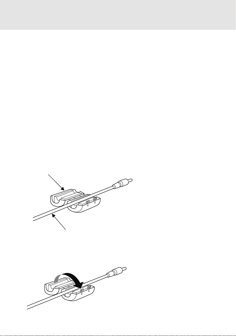
Installation of Ferrite Core
Precaution:
Ferrite core is required to install onto the Audio and Microphone cable to reduce EMI interf erence.
Before connecting the Audio cable and the Microphone cable to your LifeBook, you are require
to install the ferrite core to the Audio and Microphone cable. The ferrite core is provided together
with your LifeBook.
Please follow the procedure as describe below for the installation of the ferrite core.
STEP 1: Installing Ferrite Core
Ferrite Core
Audio Cable
STEP 2: Closing Ferrite Core
Be careful not to pinch the cable when closing the ferrite core cover, as it will damage your
cable.
iii
Page 4

DATA STORAGE MEDIA
AND CUSTOMER RESPONSIBILITIES
The only effective protection for the data stored in a computer, such as on a hard disk, is for you,
Purchaser to regularly back up the data. Fujitsu and its affiliates, suppliers, service providers and
resellers shall not be responsible for any software programs, data or other information stored or
used on any media or part of any Product returned to Fujitsu or its service providers for Warranty
Service or other repair, including but not limited to the costs of recovering such programs, data or
other information. It is solely your responsibility as the Purchaser to bac k up any software prog rams,
data, or information stored on any storage media or any part of a Product returned for Warranty
Service or repair to the designated service centers.
iv
Page 5

A USTRALIAN WARNINGS
WARNING
FOR SAFETY REASONS, ONLY CONNECT EQUIPMENT WITH A TELECOMMUNICATIONS
COMPLIANCE LABEL. THIS INCLUDES CUSTOMER EQUIPMENT PREVIOUSLY LABELLED
PERMITTED OR CERTIFIED .
Connection of Non Certified/Approved peripherals may result in the equipment operating
outside the Australian EMI Standards.
Modems connected to the Australian telecommunications network must be operated in accordance
with the Labelling Notice. This modem has been specifically configured to ensure compliance with
the ACA Standards. Do not adjust your modem or software outside the values indicated below. To
do so would result in your modem being operated in a non-compliant manner.
Call Attempts/Retries:
Applications software shall be configured so that no more than 3 attempts are made to establish a
connection to a given number (Note: if the modem can detect service tones, up to 10 attempts can
be made). If the call sequence is unsuccessful, there shall be a dela y of at least 30 min utes bef ore
attempting to call the number again.
Failure to set the modem, and any application softw are used with the modem, to the values shown
above will result in the modem being operated in a non-compliant manner . Consequently, this would
be in violation of the Labelling Notice for this equipment, and the Telecommunications Act 1997
prescribes penalties for the connection of non-compliant equipment.
v
Page 6

NEW ZEALAND WARNINGS
The grant of a Telepermit for any item of terminal equipment indicates only that Telecom has accepted
that the item complies with minimum conditions for connection to its network. It indicates no
endorsement of the product by Telecom, nor does it provide any sort of warranty. Above all, it provides
no assurance that any item will work correctly in all respects with another item of Telepermitted
equipment of a different make or model, nor does it imply that any product is compatible with all of
Telecom’s network services.
This equipment is not capable under all operating conditions of correct operation at the higher speeds
for which it is designed. 56 KBPS connections are likely to be restricted to lower bit rates when connected
to some PSTN implementations. Telecom will accept no responsibility should difficulties arise in such
circumstances.
Immediately disconnect this equipment should it become physically damaged, and arrange for its
disposal or repair.
This equipment shall not be used in any manner, which could constitute a nuisance to other Telecom
customers.
This equipment shall not be set to make automatic calls to the Telecom “111” Emergency Service.
This device is equipped with pulse dialling while the New Zealand standard is DTMF tone dialling.
There is no guarantee that Telecom lines will always continue to support pulse dialling. It is strongly
recommended that pulse dialling is not used.
Some parameters required for compliance with Telecom’s Telepermit requirements are dependent
on the equipment (PC) associated with this device. The associated equipment shall be set to operate
within the following limits for compliance with Telecom’s Specifications:
For repeat calls to the same number.
There shall be no more than 10 call attempts to the same number within any 30 minute period
for any single manual call initiation, and
The equipment shall go on-hook for a period of not less than 30 seconds between the end of
one attempt and the beginning of the next attempt.
For Automatic calls to different numbers.
The equipment shall go on-hook for a period of not less than 5 seconds between the end of
one attempt and the beginning of the next attempt.
For Automatically answered Incoming Calls
Incoming calls shall be answered between 3 and 30 seconds from the start of the ringing.
For correct operation, the total of the RNs of all devices connected to a single line at anytime should
not exceed 5. The RN of this Equipment is 0.5.
WARNING
Connection of Non Certified/Approved peripherals may result in the equipment operating
outside the New Zealand EMI Standards.
vi
Page 7
Note: Modem setting in Windows XP
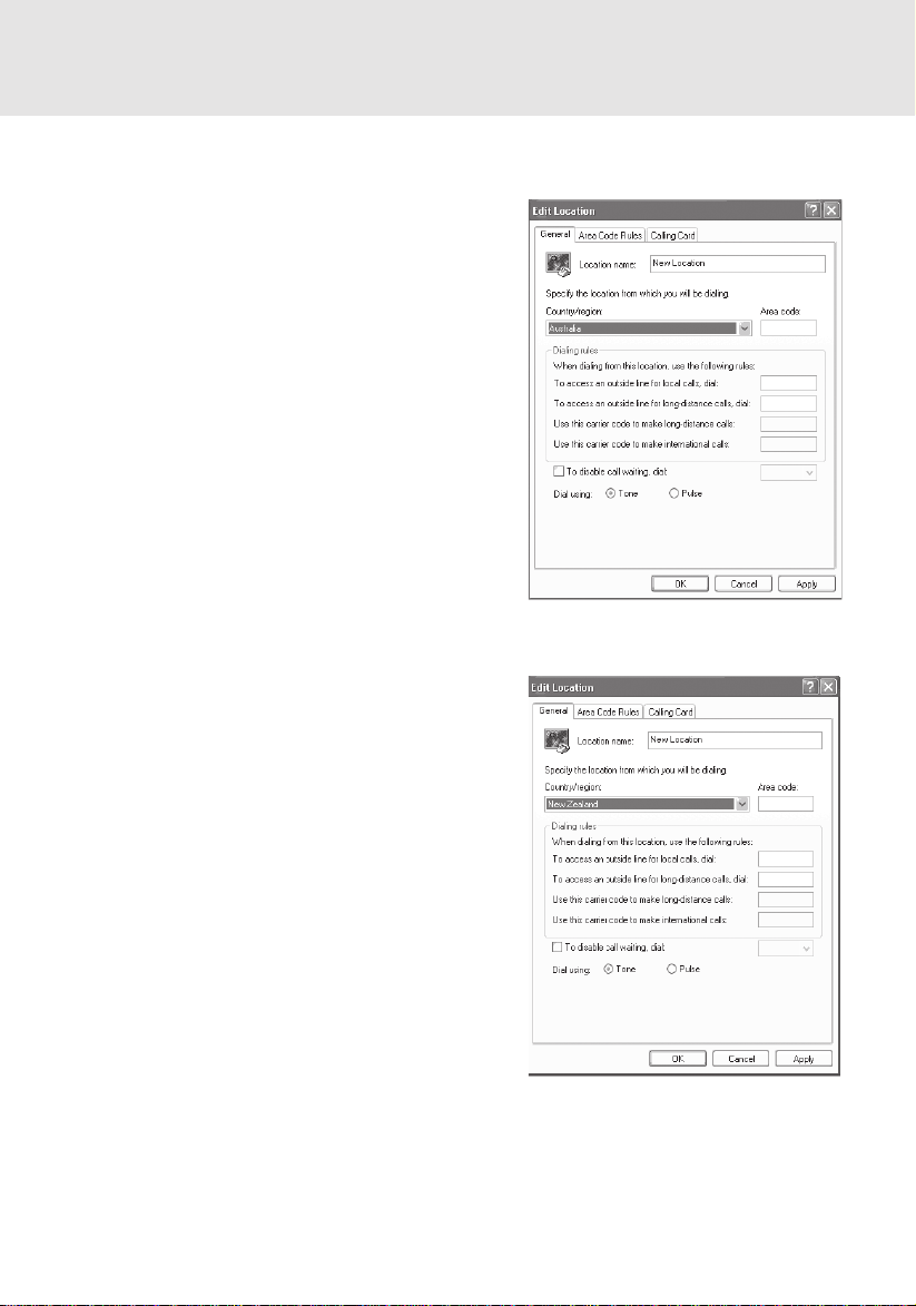
A. If you are located in Australia
1. Click Start select Control panel select “Phone and
Modem Options”.
2. Double click New Location.
3. Choose “Australia” in Country/region pull down
menu bar.
4. Select Phone system as “Tone Dialing”.
5. Click OK and Apply.
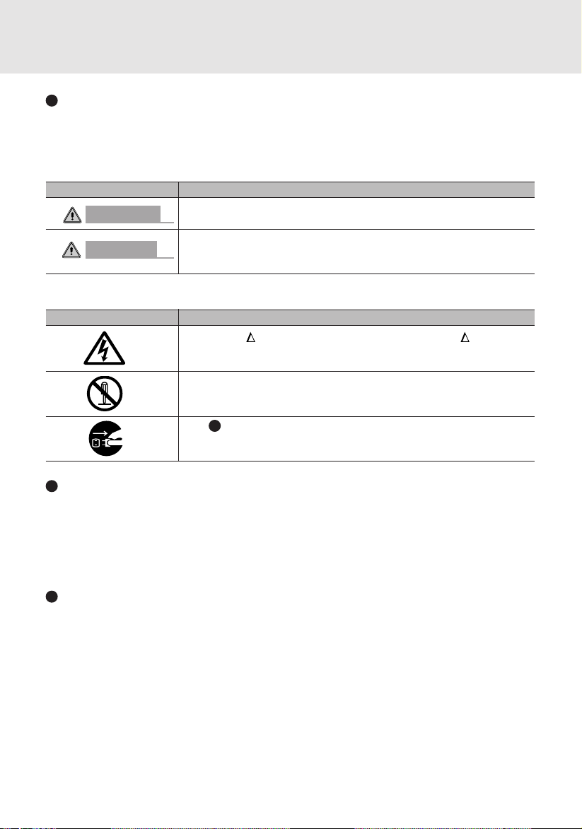
B. If you are located in New Zealand
1. Click start select Control panel select “Phone and
Modem Options”.
2. Double click New Location.
3. Choose “New Zealand” in Country/region pull down
menu bar.
4. Select Phone system as “Tone Dialing”.
5. Click OK and Apply.
Note:
The screens and illustrations shown in this examples may slightly vary depending on the operating
environment that you have installed.
vii
Page 8
NOTATION IN THIS DOCUMENT
Warnings
This manual uses a variety of icons as visual marks so that you can use this computer safely
and correctly and avoid damage and danger to yourself and to others. These icons and their
meanings are as follows. Please learn these icons before reading this manual. Learning these
icons will be useful for understanding this manual.
Icon Meaning
WARNING
CAUTION
The symbols below are used together with the icons above to indicate what type of danger or
damage is involved.
symbols Meaning
Incorrect handling ignoring this warning can cause a dangerous situation
that could result in death or severe injury.
Incorrect handling ignoring this warning can cause a dangerous situation
that could result in moderate or minor injury or could result in equipment
damage.
The symbol indicates warning or caution. The symbol indicates the
concrete nature of the warning. (The example on the left is a
caution for electric shock.)
The circle and slash indicates prohibited behavior. The symbol inside
the circle indicates the concrete nature of the prohibition. (The example
on the left indicates that disassembly is prohibited.)
The indicates instructions that must be followed. The symbol inside
indicates the concrete nature of those instructions. (The example on
the left tells you to unplug the power plug from the socket.)
Key notation and operation methods
Explanations of key operations do not show all the characters on the keyboard. Instead they
indicate just the keys necessary to the explanation as follows.
Examples: [Ctrl] key, [Enter] key , [ → ] key
When multiple keys are to be pressed at the same time, this is indicated by connecting them
with [+].
Examples: [Ctrl] + [F3] keys; [Shift] + [ ↑ ] key
Screen examples
The screens shown in this manual are examples. Please understand that the file names and
screens you use may be different.
viii
Page 9

Notation in text
Here is what symbols in text mean.
Symbol Meaning
Critical Points
Critical Point Indicates a point necessary for correctly operating the
hardware or software.
Column Gives the meaning and brief explanation of a term.
Column
→ Indicates the page to see elsewhere in this manual.
Command input (key input)
Within the text of this manual, command input (giving commands to the computer by pressing
keys) is indicated as follows.
Example:
In the position indicated in the example above by the ↑, the space left between the characters
indicates that a space needs to be left in the entry by pressing the space bar (the long key with
nothing written on it at the center of the front of the keyboard). Commands are written in this
manual as lowercase latin letters, but uppercase letters may be used.
Product names
The following product names are abbreviated as follows in this manual.
“Microsoft® Windows XP® operating system” is written as “Windows XP”.
“LifeBook” is written as “this computer” or “the computer main unit”.
dir c:
↑
ix
Page 10

x
Page 11

Configuration of this Manual
SECTION 1
This section explains basic operations and basic items for using this computer, including the
names of the parts and their functions and battery operation.
SECTION 2
This section explains installation of options for this computer.
SECTION 3
This section explains what to do when trouble occurs with this computer and when messages
are displayed. Read this section as the necessity arises.
SECTION 1
SECTION 2
SECTION 3
xi
Page 12

xii
Page 13

SECTION 1
CONTENTS
1 Names of the Parts and their Functions.................................... 2
Exterior features: Front panel......................................................................2
Exterior features: Side panels..................................................................... 4
Exterior features: Bottom panel................................................................... 7
Exterior features: Rear panel ...................................................................... 8
Exterior features: Status indicating LEDs.................................................. 10
Exterior features: Keyboard....................................................................... 12
About the ten-key mode............................................................................ 15
2 Changing the Brightness of the LCD....................................... 16
3 Before Connecting a Peripheral Device .................................. 17
4 Changing the Internal Battery Pack......................................... 18
Changing the internal battery pack ........................................................... 18
5 Running the Computer on its Battery...................................... 20
Charging the battery ................................................................................. 20
Running the computer on its battery ......................................................... 21
Checking the power level of the battery .................................................... 21
Precautions in using the battery pack ....................................................... 23
6 Adjusting the Volume ................................................................ 25
Adjusting the volume, using keys on the keyboard ................................... 25
7 Using a Memory Card................................................................ 26
Supported memory card ........................................................................... 26
Inserting a memory card ........................................................................... 26
8 Using the Mouse........................................................................ 28
Exterior features: Mouse........................................................................... 28
Scrolling by turning the scroll wheel ......................................................... 29
Scrolling by pressing the scroll wheel ....................................................... 30
9 Using the One-touch Buttons................................................... 31
About the one-touch buttons..................................................................... 31
Starting an application .............................................................................. 32
Operating music player ............................................................................. 32
xiii
Page 14

10 Wireless LAN Function ............................................................. 34
Preface...................................................................................................... 34
Notice to the user...................................................................................... 35
Representation of symbols and others in this document .......................... 37
Outline ...................................................................................................... 38
Features of the wireless LAN function ...................................................... 38
Network configuration of the wireless LAN ............................................... 38
For better communications ....................................................................... 40
When communication cannot be done normally ....................................... 41
Stopping the transmission of radio waves................................................. 41
Starting the transmission of radio waves .................................................. 41
Flow of operations..................................................................................... 43
Preparation for using the wireless LAN..................................................... 44
Connection to the Network....................................................... 50
Setting the network ................................................................................... 50
Setting the sharing function ...................................................................... 53
Confirming connection .............................................................................. 57
Appendix .................................................................................... 60
Other settings ........................................................................................... 60
Setting of channels during ad hoc connection .......................................... 60
Troubleshooting......................................................................... 61
Unavailable connection to the network ..................................................... 61
xiv
Page 15

SECTION 2
SECTION 3
1 Connecting a Printer ................................................................. 68
Preparing what are needed ...................................................................... 68
Connecting a printer ................................................................................. 68
2 Connecting a USB Device......................................................... 69
Preparing what are needed ...................................................................... 69
Connecting a USB device ......................................................................... 70
3 Installing Memory ...................................................................... 71
Preparing what are needed ...................................................................... 71
Installing memory...................................................................................... 71
Changing the memory .............................................................................. 76
1. When This Happens ................................................................... 82
2. Maintenance of your Computer................................................ 86
xv
Page 16

xvi
Page 17

1
This section explains basic operations and basic
items for using this computer, including the
names of the parts and their functions and battery
operation.
SECTION 1
1
Page 18
SECTION 1
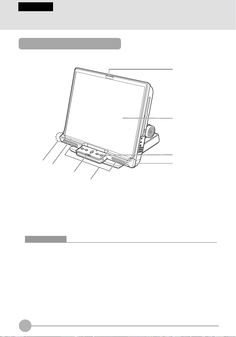
1 Names of the Parts and their Functions
Exterior features: Front panel
1
2
3
4
7
6
5
1. Infrared/remote-control detector
Detects infrared rays from the wireless keyboard and wireless mouse.
Do not touch this window when wireless communications are held. Doing so could cause
degradation in communication performance.
2. LCD (Liquid Crystal Display)
Information display device of your computer.
4
Critical Points
The phenomena described below are due to the characteristics of LCD panels and do not
indicate that LCD panels are defective.
About the characteristics of LCD panels
• Your computer’ s LCD was manufactured through the use of high technologies . F or technical
reasons, your LCD might have picture elements or dots that do not light up or those that
always stay on.
• Colors reproduced by LCD panels vary to some extent from product to product for reasons
of manufacturing processes. Also, a slight une venness of density ma y show up as a result
of changes in temperature.
Using the LCD dimmed for a long period of time could shorten the life of its backlight.
2
Page 19

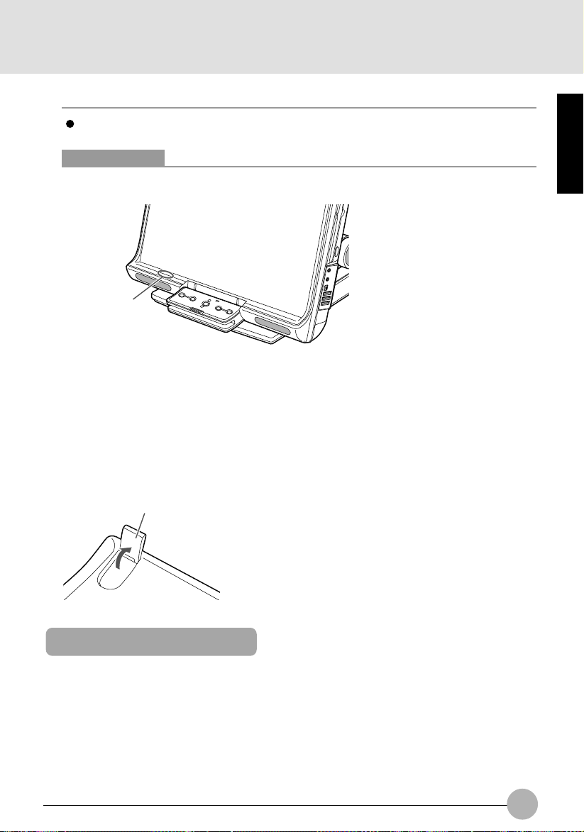
3. One-touch buttons
Used to start applications or play music CDs.
4. Infrared remote-control detector
Detects infrared rays from the wireless keyboard and wireless mouse.
Do not touch this window when wireless communications are held. Doing so could result in
degradation in communication performance.
5. Speakers
Sound output devices of your computer.
6. Keyboard lock
Allows you to lock and unlock the connection between the computer and the wireless
keyboard.
7. Status indicating LEDs
Indicate the operating status of your computer.
SECTION 1
3
Page 20
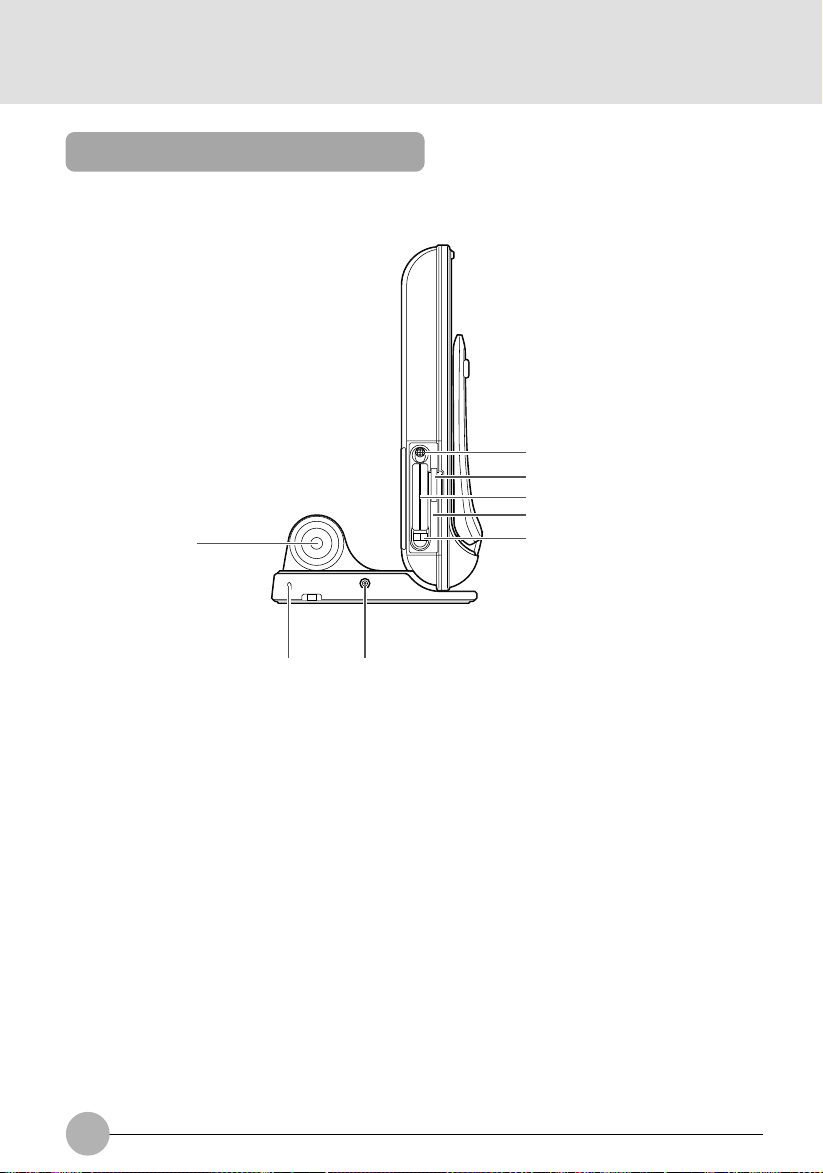
Exterior features: Side panels
❑ Left panel of the computer
1
2
3
4
6
7 8
1. Power switch
Used to turn on the computer, to place it into standby (hibernation) mode, and to resume system
operation. Slide the s witch to the O position to turn Off the computer , or to the position to 1 turn
it On.
5
2. SD card/memory card slot
Allows you to insert an optional memory card.
3. PC card slots
Allows you to insert optional PC cards. The slot on the right side and the slot on the left side are
called slot 1 and slot 2, respectively.
4. Wireless Switch
Used to turn On and Off the Wireless LAN device.
5. PC card eject buttons
Used to eject the PC card.
6. Woofer
A Hi-Fidelity speaker that provides superb audio performance.
4
Page 21
7. Antitheft lock
Allows you to connect a commercially available antitheft cable to your computer.
Critical Points
The antitheft lock is designed for Kensington Microsaver Security System.
8. DC-IN jack
Used to connect the supplied AC adapter.
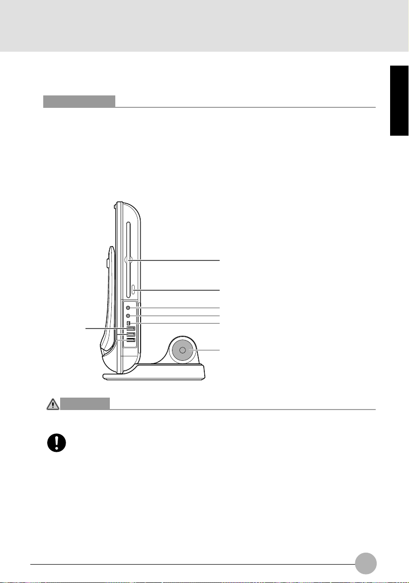
❑ Right panel of the computer
1
2
3
4
7
5
6
SECTION 1
CAUTION
HEARING LOSS
• Before connecting headphones or a microphone to your computer , always turn down
your computer’s master volume to a minimum.
Failure to do so could result in damage to the audio unit connected or could adversely
affect your hearing.
5
Page 22
1. CD/DVD drive
Your computer comes standard with a CD-RW/DVD-ROM drive. The CD/DVD drive allows you
to read information from CD/DVDs and play music CDs and DVD-Videos.
2. CD eject button
Press this button to insert a disk in the CD/DVD drive or to eject it. This b utton is operative only
when the computer is turned on.
3. Mic (microphone) jack
Allows you to connect a commercially available monaural microphone with a Ø3.5 mini-plug.
This jack does not support some types of microphones (e.g., dynamic microphone), so you
should consult a salesperson before purchasing a microphone.
4. Headphone jack
Allows you to connect commercially av ailable headphones with a Ø3.5 mini-plug. This jac k is not
compatible with some types of cable connectors, so you should consult a salesperson before
purchasing headphones.
CAUTION
HEARING LOSS
• When you are listening to music with headphones, be careful not to turn up the
volume excessively. Listening to very loud sounds for a long time could adversely
affect your hearing.
• When you are wearing headphones connected to the computer, do not turn or off
the computer, or very loud sounds could adversely affect your hearing.
5. IEEE* 1394 (DV) port (*: pronounced “ai-triple-ee”)
Allows you to connect a peripheral device, such as a digital video camera (D VC), to the computer
through a DV cable.
6. Woofer
A Hi-Fidelity speaker that provides superb audio performance.
7. USB port
Allows you to connect a peripheral device compliant with USB standard.
6
Page 23
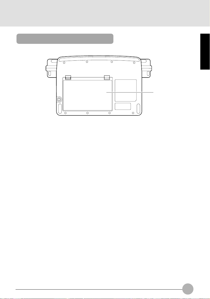
Exterior features: Bottom panel
(Your computer or situation may not look exactly like this illustration.)
1. Internal battery pack
An internal battery pack is installed here.
SECTION 1
1
7
Page 24
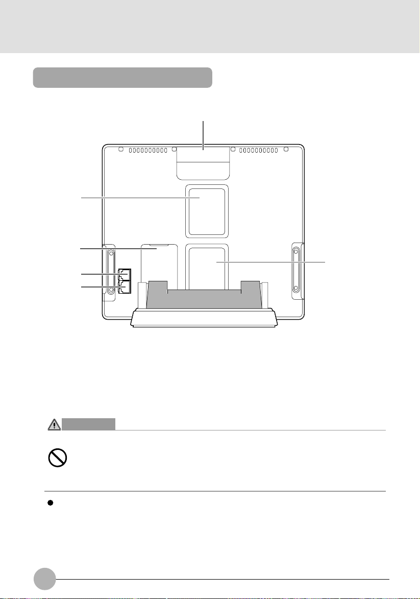
Exterior features: Rear panel
1
2
3
6
4
5
1. Handle
Used when carrying your computer.
2. Air outlet
Opening through which heat is forcibly discharged from the computer. When you turn on the
computer, the cooling fan rotates f or a fe w seconds. When the temperature in the computer rises
high, the cooling fan automatically starts to rotate to discharge heat from the computer.
W ARNING
ELECTRIC SHOCK
• Do not obstruct the air outlet. Doing so prevents heat from being discharged from
the computer and could result in damage to your computer.
IMPORTANT
Do not put anything around the air outlet. Objects placed around it, if any, may be heated by
heat discharged through the air outlet.
3. Expansion RAM module slot
Used to install additional memory.
8
Page 25
4. Modem port
Allows you to connect your computer to a phone line through the supplied modular cable for
using an online service or browsing the Internet.
5. LAN port
Allows you to connect your computer to a LAN (local area network), using an optional LAN
cable.
6. Air inlet
Opening through which the cooling fan takes outside air into the computer.
CAUTION
FAILURE
• Be careful not to obstruct the air inlet.
Doing so prevents heat from being discharged from the computer and could result
in damage to your computer.
SECTION 1
9
Page 26
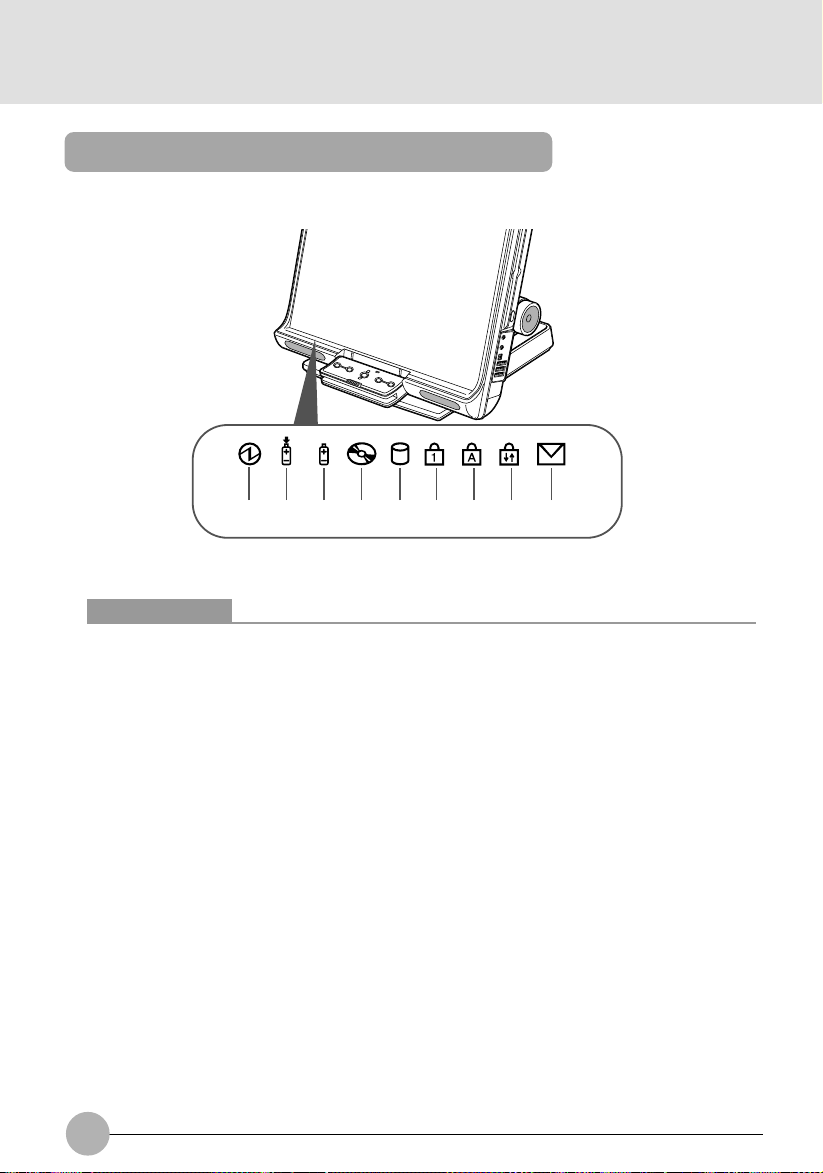
Exterior features: Status indicating LEDs
1 2 3 4 5 6 7 8 9
(Your computer or situation may not look exactly like this illustration.)
Critical Points
When your computer is turned off, no indicators are display ed on the status indicating LCD,
except when the battery pack is being charged.
1. Power indicator
Indicates the operating status of the computer.
• Lit green: The computer is turned on.
• Blinks green: The computer is on standby.
• Not lit: The computer is turned off.
2. Charging status indicator
When the AC adapter is connected to your computer, this indicator lets you know whether the
battery pack is being charged.
• Lit green
Fully charged or not charged because no battery pack is installed
• Lit orange
Being charged
• Blinks orange
Charging suspended (because a battery temperature alarm was set off *)
• Not lit
Not charged because no AC adapter is connected
* : If the internal battery becomes very hot or cold for some reason, the battery protection
feature will be activated and set off a battery temperature alarm to stop charging the battery .
10
Page 27

3. Power level indicator
Indicates the state of charge or remaining life of the internal battery pack.
• Lit green
Between 51% and 100% charged*
• Lit orange
Between 50% and 13% charged*
• Lit red
Between 0% and 12% charged*
• Blinks orange
Measuring the remaining life of the internal battery pack (4 seconds after being installed)
• Blinks red
Something is wrong with the battery.
• Not lit
No battery installed
Critical Points
If you install the internal battery pack when the computer is off, the power le v el indicator will
blink for a while, then indicate the power level of the battery pack for 5 seconds. Or it will
turns off if the battery pack is not charged.
If the AC adapter is not connected when the internal battery pack is installed, the power
level indicator will not stay on but blink at intervals of 6 seconds: ON f or 1 second and OFF
for 5 seconds.
4. CD access indicator
Lit when access is being made to the CD.
5. Hard disk access indicator
Lit when access is being made to the hard disk.
Critical Points
Never press the power button when the hard disk access indicator is lit. Doing so could
result in the corruption of data on the hard disk.
SECTION 1
6. Num Lock (Numerical Lock) indicator
Lit when the keyboard is placed in [Num Lock] mode.
To enter or exit [Num Lock] mode, press the [Num Lock] key.
7. Caps Lock key
Lit when the keyboard is placed in [Caps Lock] mode.
T o enter or exit [Caps Lock] mode, press the [Caps Loc k] ke y while holding down the [Shift] ke y.
8. Scroll Lock indicator
Lit when the window is locked so that it cannot be scrolled up or down.
To enter or exit [Scroll Lock] mode, press the [Num Lock] key while holding down the [Fn] key.
The reaction of the window depends on the application used.
9. Incoming mail indicator
Blinks each time you get incoming e-mail if a one-touch button is so set up.
11
Page 28
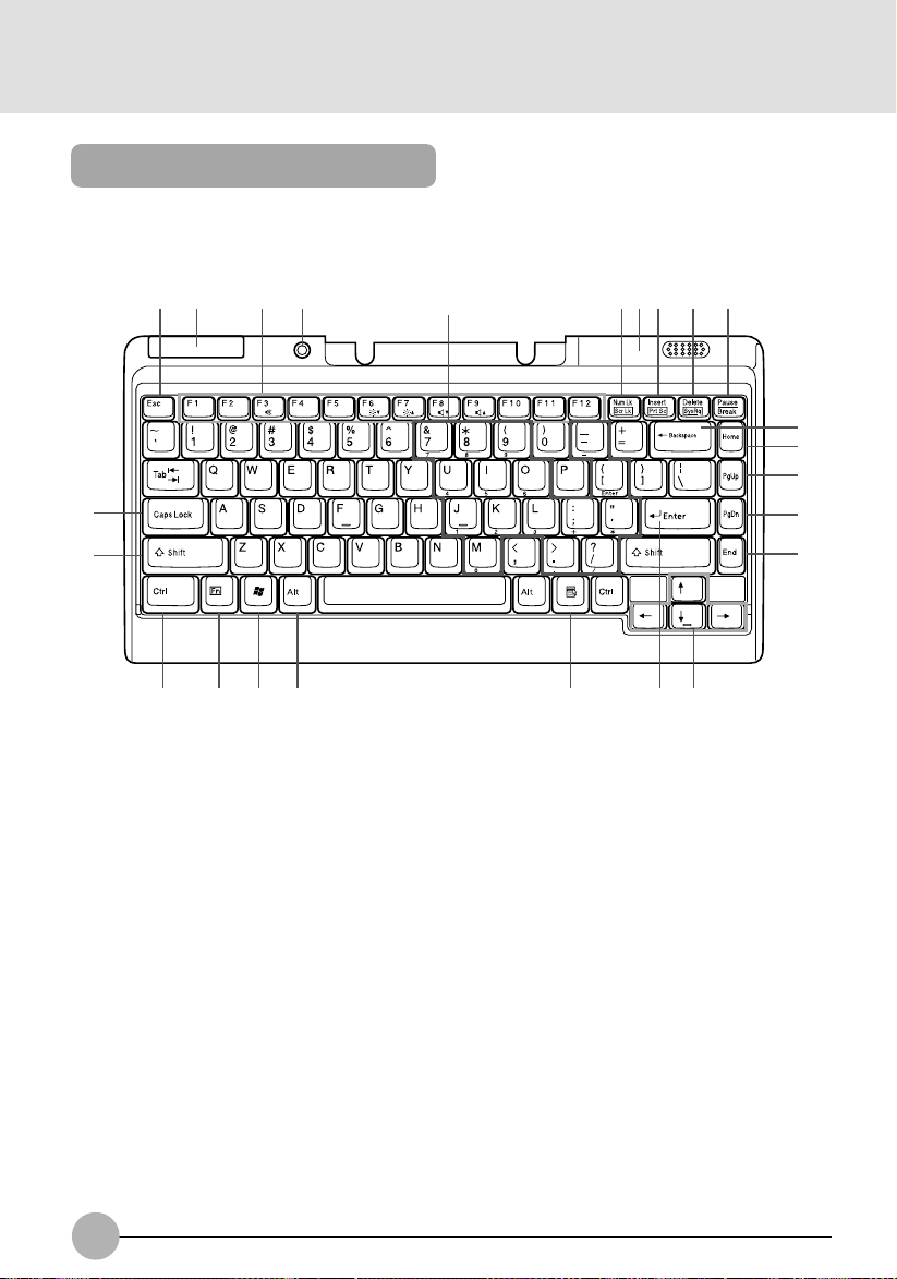
Exterior features: Keyboard
You can jump to the information you want by clicking the corresponding alphabetic character.
❑ Main keys and their functions
1 2 3 4 Ten-key 5 6 7 8 9
10
11
12
23
22
21 20 19 18 17 16 15
1. [Esc] (Escape) key
Used to cancel the task currently performed to return to the previous task.
2. Infrared remote-control emitter
Sends commands from the keyboard to the computer . Do not put anything between the keyboard
and the computer when communications are held. Doing so could result in degradation in
communication performance.
3. Function keys
Functions assigned to these keys vary from application to application.
4. Power button
Used to turn on the computer, to place it into standby (hibernation) mode, and to resume system
operation.
5. Num Lock (Numerical Lock) indicator
Press the [Num Lock] key to enter the ten-key mode. Press the key again to exit the ten-key
mode.
13
14
6. Battery case
To use the keyboard, you need to insert two AAA batteries in this case.
12
Page 29

7. [Insert] key / [Prt Sc] key
• [Insert] key
Used to switch between insertion and overtype modes.
• [Prt Sc] (print screen) key
Used to convert the information displayed in windows into pictorial data. To do so, press this
key while holding down [Fn] key.
T o conv ert the information in the only active window , press the [Insert] key while holding down
the [Alt] and [Fn] keys.
To edit, save or print the pictorial data, start an paint program, such as Paint, after pressing
these keys, and select “Paste” from the “Edit” menu.
8. [Delete] key
Used to delete characters on the left side of the cursor or to delete the file or icon selected.
You can also use this key to exit an application that does not respond to any command or to
forcibly shut down your computer. To do so, press the [Delete] key while holding down the [Ctrl]
and [Alt] keys.
9. Pause / Break key
Pause key
Press this key to pause the scree display.
• Break
Its function depend on the application software.
10. [Back Space] key
Used to delete characters on the left side of the cursor.
11. [Home] key
Used to return the cursor to the beginning of the line on which the cursor is currently placed. To
do so, press the key.
To return the cursor to the beginning of the document, press the key.
SECTION 1
12. Pg Up] (page up) key
Used to return to the previous window. T o do so , press this k e y while holding down the [Fn] k e y.
13. [Pg Dn] (page down) key
Used to move to the next window. To do so, press the key.
14. [End] key
Used to move the cursor to the end of the line on which the cursor is currently placed. To do so,
press the key.
To return the cursor to the end of the document, press the key.
15. Cursor (arrow) keys
Used to move the cursor on the screen.
16. [Enter] key
Used to confirm the word your entered or the selection you made.
This key is also called the return key, because pressing it star ts a new paragraph in word
processing.
13
Page 30

17. [Application] key
Used to display the pop-up menu of the item selected. This button can be used in place of the
right button on the flat point.
18. [Alt] key
Used in combination with other keys.
19. [Windows] key
Used to open the “Start” menu.
20. [Fn] key
This key, unique to your computer, is used in combination with other keys.
• [Fn] + [F3]
Turns on and off the speakers and headphones.
• [Fn] + [F6]
Dims the backlight of the LCD panel.
• [Fn] + [F7]
Brightens the backlight of the LCD panel.
• [Fn] + [F8]
Turns down the volume.
• [Fn] + [F9]
Turns up the volume.
* : The plus sign [+] coupling two keys means that the second k ey m ust be pressed with
the first key held down. For example , [Fn] + [F3] means that y ou must press the [F3]
key while holding down the [Fn] key.
21. [Ctrl] key
Used in combination with other keys.
22. [Shift] key
Used in combination with other keys. T o type an alphabetic character in uppercase or the symbol
printed in the upper area of a key, press the appropriate key while holding down the [Shift] ke y.
23. [Caps Lock] key
Used to switch between uppercase and lowercase modes. To do so, press this key.
14
Page 31
IMPORTANT
Some keys may not function as described above, depending on the system configuration.
Critical Points
The keyboard indicator is displayed on the status indicating LED.
Keyboard indicator
To switch to one of the following modes, press the appropriate key or combination of ke ys.
Then the indicator for the mode you selected appears on status indicating LED panel. To cancel
the mode selected, press the key or combination of keys again.
• Num Lock : [Num Lock] key
• Caps Lock : [Caps Lock] key
• Scroll Lock : [Fn] key + [Scroll LK] key
The tilt feet on the bottom of the ke yboard allow y ou to tilt the ke yboard so that you can type
more efficiently.
Tilt foot
SECTION 1
About the ten-key mode
The ten-key mode refers to the mode in which you can use part of the keyboard as a ten-key
numerical pad (that allows you to type in numeric characters more easily). Press the [Num Lk] key to
place your keyboard into ten-key mode. When the keyboard is in ten-key mode, the Num Lock
indicator is displayed on the status indicating LED. In ten-key mode, you can enter the numeric
character printed on the front face of each numeric key.
15
Page 32

SECTION 1
2 Changing the Brightness of the LCD
The brightness of your computer’s LCD (Liquid Crystal Display) can be adjusted in 8 steps. Your
computer is factory-configured so that the brightness of the LCD will increase when the computer
runs on AC power, while it will decrease a little when the computer runs on its battery.
You can adjust the brightness individually for each power supply mode: power supply from A C outlet
or power supply from battery.
1. Place your computer into the power supply mode for which you want to adjust the
brightness.
• Power supply from AC outlet: Connect the AC adapter to your computer.
• Power supply from battery: Disconnect the AC adapter from your computer.
2. Adjust the brightness.
• To turn up the brightness: Press the [F7] key while holding down the [Fn] key.
• To turn down the brightness: Press the [F6] key while holding down the [Fn] key.
An indicator showing the brightness of the LCD appears at the bottom of your desktop.
Dim Bright
Critical Points
If you change the brightness with the keyboard immediately after restarting your computer,
resuming system operation, or connecting or disconnecting the AC adapter , the change you
made may not take effect. In such a case, change the brightness again a few moments later.
If you connect or disconnect the AC adapter while Windows is running, the message “Fujitsu
Hotkey Utility has changed the brightness” will appear on y our desktop . Then follow the onscreen instructions to perform necessary steps.
16
Page 33

SECTION 1
3 Before Connecting a Peripheral Device
This section explains what your should keep in mind when connecting a peripheral device to your
computer.
• Some peripheral devices need to be set up before use.
You cannot make all peripheral devices ready to use by simply connecting them to a computer.
Depending on the peripheral device you use, you might need to set it up after connecting to y our
computer. F or example, to use a printer or PC card along with your computer , y ou need to “install
its driver.” On the other hand, there are also peripherals such as memory that require no setup.
So before connecting a peripheral device, read this manual carefully and connect it correctly.
• Read this manual carefully.
Follow the instructions in this manual to connect a cable correctly. Connecting a cable incorrectly
could result in damage to your computer or peripheral device.
The ways to connect cables shown in this manual are just a few examples. So for the way to
connect your peripheral device, ref er also to its user guide.
• Use Fujitsu genuine devices.
For optionally available Fujitsu genuine devices, contact your authorized distributor or use the
fax information service.
Fujitsu can provide no guarantee that devices manufactured by other makers operate normally
on your computer. If you want to use a device other than Fujitsu genuine devices, contact the
maker.
• Use ACPI-compatible peripheral devices.
Your computer is factory-configured so as to meet ACPI (Advanced Configuration and Power
Interface: A battery power management scheme).
The use of a peripheral device that does not support ACPI could cause the power saving f eatures
of your computer to malfunction.
Your computer does not support the low-level standby mode (ACPI S1).
If your peripheral device supports only the low-level standby mode, do not place your computer
into standby or hibernation mode.
• Turn on peripheral devices before turning on your computer.
When a peripheral device that needs to be switched on for use is connected to your computer,
turn it on before turning on the computer, and turn it off after turning off the computer.
SECTION 1
IMPORTANT
When connecting a peripheral device to a port on your computer, make sure the plug is
oriented correctly and insert it straight into the port.
When connecting two or more peripheral devices to your computer, connect and set up
them one by one.
17
Page 34

SECTION 1
4 Changing the Internal Battery Pack
W ARNING
ELECTRIC SHOCK
• Be sure to turn off your computer before changing the internal battery pack. To
avoid shock hazards and fire, be careful not to touch internal components of the
computer, including the battery connector.
Changing the internal battery pack
1. Turn off your computer.
2. Tip your computer with LCD facing upward.
IMPORTANT
Tip your computer toward you carefully so that it will not hit against anything.
18
Page 35

3. Remove the internal battery pack while pressing the tabs in the direction of the arrow.
The internal battery pack is detached from the connector.
Tab
Internal battery pack
Tab
4. Install a new battery pack
Insert the new battery pack into the battery housing with the slit in the battery pack aligned with
the projection on the computer, and push in the battery pack until it clicks into place.
Tab
Internal battery pack
Tab
SECTION 1
IMPORTANT
After removing the internal battery pack, take necessary measures to prevent a short circuit,
for example, sealing its connector with an insulating tape. After removing the battery pack,
do not mix it with other types of battery.
The internal battery pack (lithium-ion battery) contains precious resources. Therefore, you
should dispose of the disused battery pack as a recyclable material if possible.
19
Page 36

SECTION 1
5 Running the Computer on its Battery
Charging the battery
1. Connect the AC adapter to your computer.
2. The charging status indicator lights up.
It indicates whether the battery pack is being charged.
3. When the charging status indicator turns green, disconnect the AC adapter from your
computer.
Critical Points
Charge the supplied battery pack before using it for the first time after purchase or if it is not
recharged for more than one month.
To fully charge the battery pack, continue charging until the charging status indicator turns
green.
When the battery pack is 90% or more charged, it cannot be recharged even when the AC
adapter is connected. The battery pack can be recharged when its power le vel (or remaining
battery life) is 89% or less.
The chargeability of the battery pack decreases when it is charged in an very hot or cold
place.
When the battery pack is very hot, for example , immediately after the use of the computer,
the battery protection feature may be activated to pre vent the battery from being recharged.
(If this happens, the charging status indicator blinks orange.) When the battery temperature
comes down, your computer automatically restarts to charge the battery pack.
20
Page 37

Running the computer on its battery
This section explains how to run your computer on its battery pack.
1. Disconnect the AC adapter from your computer and press the power button to start the
computer.
Power button
Critical Points
Turn on the main power switch if it is in the OFF position.
The operating time of the battery pack shortens when it is used in a cold place.
The chargeability of the battery pack decreases after it has been used over a long period of
time, and its operating time shortens accordingly. If the battery runs down soon, replace it
with a new battery.
A rise in the battery temperature may slow down your computer . If this happens, connect the
AC adapter to your computer.
SECTION 1
Checking the power level of the battery
When the computer is turned on or the battery is being charged, the power level indicator lights up
or blinks to let you know the state of charge of the internal battery pack.
❑ The way the power level indicator shows the power level
Lit when the computer is running or blinks when the computer is on standby.
Lit/blinks green: Battery is between about 51% and 100% charged.
↓
Lit/blinks orange: Battery is between about 13% and 50% charged.
↓
Lit/blinks red: Low battery condition (about 12% or less charged) or dead battery condition
(0% charged). When the battery starts to run low (low battery condition), your
computer sounds a low battery alarm through the speakers.
21
Page 38

Critical Points
For reasons of the characteristics of lithium-ion batteries, the power level indictor may not
correctly indicate the state of charge of the battery under certain conditions (temperature
conditions, number of times the battery has been discharged and recharged, and so on).
When the battery is 90% or more charged, it cannot be recharged even when the AC adapter
is connected to your computer. The battery can be recharged when its power le vel is 89% or
less.
❑ Battery temperature alarm (charging status indicator)
If the battery pack becomes very hot or cold, the charging status indicator will blink orange to tell that
the battery protection feature has been activated and stopped charging the battery . When the battery
pack temperature returns to normal, the charging status indicator stops blinking and turns orange,
and your computer automatically restarts to charge the battery pack.
❑ Battery failure alarm (power level indicator)
If the battery pack cannot be charged normally, the power level indicator will blink red.
Critical Points
If the power level indicator blinks red, turn off the computer and remove and reinstall the
battery pack correctly . If the power le vel indicator b links red e v en though the battery pack is
installed correctly , it is in a defectiv e condition or at the end of its useful life. So replace it with
a new one.
❑ Low battery condition
When the battery is discharged to a very low level, the power le vel indicator lights or blinks red. If this
happens, connect the AC adapter to your computer immediately to recharge the battery.
22
Page 39

Critical Points
The use of a weak battery may result in the lost of the data you are currently creating or
saving. When the battery starts to run low, connect the AC adapter to your computer as
soon as possible, or if no AC adapter is av ailable, immediately sa ve the data you are creating,
exit all programs and turn off your computer.
Reading or writing data on the hard disk requires a large amount of electric power. Therefore,
when the battery is weak, connect the AC adapter to your computer before reading or writing
data on the hard disk.
Leaving the battery weak for a specific period of time causes the computer to automatically
go into standby mode. When data is being read or written on the hard disk, however, the
computer does not go into standby mode before the reading or writing of data is complete.
Your computer is configured by default so that it will go into standby mode when the power
level reaches about 3%.
Precautions in using the battery pack
W ARNING
ELECTRIC SHOCK
• The battery pack is shock-sensitive. To avoid damage due to shock, be careful not
to drop the battery pack when installing or removing it. F or saf ety’s sake, do not use
any battery that has been given a strong impact. The use of a damaged battery
could results in an electric shock or explosion.
• Do not take the battery apart
T aking the battery apart or touching its internal components could result in an electric
shock or fire.
SECTION 1
• About electrical discharge
- It is good practice to always recharge the battery before use since it is discharged
spontaneously.
- When you know you will not use the computer for an e xtended period of time (for
one month or more), remove the battery pack from your computer and store it in
a cool place. Leaving the battery in the computer without recharging for a long
period of time exhausts it and shortens its useful life.
23
Page 40

• About the battery life
- Batteries are consumable and gradually deteriorate with the passage of time
even when they are not used. Therefore, to check the condition of your battery
pack, you should run your computer on the battery pack at least once a month.
- Leaving the battery pack in a hot place for a long time accelerates the deterioration
of the battery.
- The battery pack is consumable and its chargeability decreases gradually as it
is used. When the battery reaches the end of its useful life, replace it with a ne w
one.
- The battery becomes exhausted in a very short time when its useful life is ending.
- When the battery reaches the end of its useful life, remove it from the computer .
Leaving a dead battery in the computer could cause shock hazards or fire.
• About the disposal of the battery pack
- Before disposing of the battery pack, take necessary measures to prevent it
from shorting, for example, sealing its connector with an insulating tape. After
removing the internal battery pack, do not mix it with other types of battery.
The internal battery pack (lithium-ion battery) contains precious resources.
Therefore, you should dispose of the disused battery pack as a recyclable material
if possible.
• About the operating time
- The energy saving features of your computer helps you conserve battery power .
- Battery life greatly varies depending on the ambient temperature. The life of a
battery may shorten when it is used in a cold place.
• You should power your computer from the AC adapter when:
- Using an online service or navigating the Internet
- Using the hard disk or DVD/CD drive frequently
- Connecting to a LAN
- Resetting the computer to the factory defaults
- Connecting two or more external devices, such as PC cards and USB devices ,
to your computer at the same time.
24
Page 41

SECTION 1
6 Adjusting the Volume
You can use either keys on the keyboard or the volume control to adjust the volume of the speakers
or headphones.
Adjusting the volume, using keys on the keyboard
❑ Adjusting the volume of the speakers or headphones
1. Press the [F8] or [F9] key while holding down the [Fn] key.
To turn down the volume:
Press the [F8] key while holding down the [Fn] key.
To turn up the volume:
Press the [F9] key while holding down the [Fn] key.
During volume adjustment, a volume level indicator is displayed at the bottom of your desktop.
Min. volume Max. volume
(Your computer or situation may not look exactly like this illustration.)
❑ Turning on or off the speakers or headphones
1. Press the [F3] key while holding down the [Fn] key.
If the speakers or headphone connected are ON:
An indicator showing the current volume level appears on the screen.
If the speakers or headphone connected are OFF:
The message “Mute” appears and the icon is displayed.
SECTION 1
25
Page 42
SECTION 1
7 Using a Memory Card
Supported memory cards
The SD card/memory stick slot allows you to insert a memory card for digital cameras and to copy
pictures directly from it.
The SD card/memory stick slot supports two different types of memory cards (though you can insert
only one card at a time), so that, if you have digital cameras that use different types of memory
cards, you will not need to prepare an adapter for each of them.
Here are the memory cards that the SD card/memory stick slot supports.
Memory card Storage capacity
SD memory card 8 MB to 256 MB
Memory stick 4 MB to 128 MB
Critical Points
The SD card/memory stick slot does not support any copy protection technologies, such as
Magic Gate.
Inserting a memory card
IMPORTANT
For the handling of data recorded in your memory card, refer to the instruction manuals for
you memory card and device with which the memory card is used.
If you are using memory cards for your digital camera, do not format them with Windows XP.
Doing so makes it impossible to use the memory cards with your digital camera.
If you have memory cards formatted with Windows, ref ormat them with your digital camera.
For the way to format memory cards with your camera, refer to your camera’s instruction
manual.
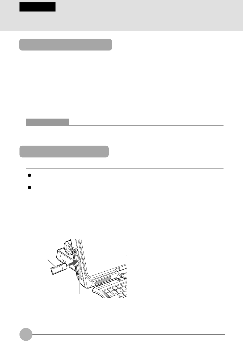
1. Inert the memory card in the SD card/memory stick slot.
Make sure the memory card is oriented correctly and push it into the slot until it clicks into place.
Memory stick
SD card/memory stick slot
(This illustration shows how to insert a memory stick.)
26
Page 43

IMPORTANT
When removing a memory card from the SD card/memory stick slot, do not push the memory
card strongly. Doing so could cause the memory card to jump out and disappear or be
broken when you take your hand off the card.
When pulling out a memory card, be careful not to distort the card by pulling it out diagonally
or applying excessive force.
When removing a memory card from the SD card/memory stick slot, keep you face away
from the slot and do not direct the memory card toward anyone. A memory card could cause
injury if it jumps out.
SECTION 1
27
Page 44

SECTION 1
8 Using the Mouse
Exterior features: Mouse
❑ Top view
1
3
❑ Bottom view
2
4
5
1. Left button
Used for clicking.
2. Right button
Used for right-clicking.
3. Scroll wheel
Used to scroll up and down though a document. You can either press or turn this wheel.
28
Page 45

4. IR (infrared) switch
Used to switch the intensity of infrared between high and low.
5. Battery case
To use the mouse, you need to insert two AAA batteries in this case.
Critical Points
The wireless mouse might not operate normally , depending on the environment in which it is
used.
If needed, you can change the functions assigned to the left and right mouse buttons.
If the ball on the back of the mouse is dirty, the mouse will not operate normally. You can
remove and clean the ball. For the cleaning of the ball, see “Care and cleaning of hardware.”
Scrolling by turning the scroll wheel
1. Click the area where the document you want to scroll is displayed.
The area where you want to scroll is confirmed.
2. Turn the scroll wheel backward.
The document you selected is scrolled up.
To scroll down the document, turn the scroll wheel forward.
SECTION 1
29
Page 46

Scrolling by pressing the scroll wheel
1. Click the area where the document you want to scroll is displayed.
2. Press the scroll wheel.
The mouse pointer symbol changes.
3. Move the mouse in the direction in which you want to scroll the document.
The document is scrolled in the direction you specified.
To return the pointer symbol to the original one, press the scroll wheel again or click the mouse
left button.
Critical Points
You can adjust the scrolling speed.
The scrolling speed changes according to the distance between the point where you pressed
the scroll wheel and the point to which you moved the mouse.
The scroll wheel does not always function in the same way.
The function of the scroll wheel varies depending on the application used, or the scroll
wheel cannot be used for some applications.
30
Page 47

SECTION 1
9 Using the One-touch Buttons
About the one-touch buttons
The one-touch-buttons allow you to call up various features of your computer. By simply pressing
one of them, you can start an application, check for incoming e-mail, or play a music CD.
(1) A
(2) B
Mode button
(3) Internet
(4) E-mail
(Your computer or situation may not look exactly like this illustration.)
Each time you press the mode button, the one-touch buttons s witch between Application mode and
Player mode and the indicator for the mode selected lights up . Pressing and holding down the mode
button for about 2 to 3 seconds locks and disables the one-touch buttons.
SECTION 1
Mode Function of one-touch button
Application Starts applications.
(The upper indicator is lit.)
Player Operates Music Player.
(The lower indictor is lit.)
Lock The one-touch buttons are locked
(Both the upper and and cannot be used.
lower indicators are off.)
Critical Points
To exit the Lock mode, press and hold down the mode button for about 2 to 3 seconds.
The mode indicator stays on, e ven when the computer is in standby mode or turned off. To
turn off the mode indicator, press and hold down the mode button for 2 to 3 seconds, or
change one-touch button settings so that the one-touch buttons will be disabled when the
computer is in standby mode or turned off.
31
Page 48

Starting an application
When the mode selector is in the Application position (Up), you can start one of the applications
below, simply by pressing the one-touch button assigned to it.
Buttons Application Started (Factory default setting)
(1) A-button Notepad
(2) B-button Calculator
(3) Internet button *1 Internet Explorer
(4) E-mail button *2 Outlook Express
*
1: If you are subscribe to your local Internet service provider(ISP)
*
2: You need to set up @Mail before using this button.
Operating music player
When the one-touch buttons are in player mode, you can use them to operate Music Player.
Buttons
(1) Stop/Eject (2) Play/Pause (3) Previous (4) Next track
3*
By pressing the Previous or Next track button, you can skip to the previous or next song
when you are using Music Player.
32
Page 49

If you insert a music CD in the CD/DVD drive when Windows is running, Music Play er will automatically
start and play the CD. To control the playback of the CD, you can use either the one-touch buttons
Music Player.
IMPORTANT
Do not use the one-touch buttons for any type of CD/D VD e xcept music CDs. Doing so could
cause your computer to malfunction.
Critical Points
Copy control CDs are not compliant with the current music CD standard. Therefore, there is
no guarantee that they can be played normally with your CD-RW/DVD-ROM drive. If any
problem arises during the playback of a copy control CD, contact its distributor. Every CD
SECTION 1
33
Page 50

SECTION 1
10 Wireless LAN Function
Preface
Thank you for purchasing the Fujitsu LifeBook.
This document describes the setup of this personal computer for using the Wireless LAN
compliant with IEEE802.11b.
Before starting up this personal computer, read this document and operate the computer properly.
34
Page 51

Notice to the user
❑ Wireless interoperability
This personal computer is designed so that it achieves the collaboration of an intercommunications
system with Wireless LAN products based on the wireless LAN technology of the Direct Sequence
Spread Spectrum (DD-SS) scheme. This personal computer also complies with the Wireless
LAN Standard “Wi-Fi” defined b y the “Wi-Fi Alliance” which verifies interconnectability between
Wireless LAN products.
❑ Effects of radio-wave radiation on environments
• As with other high-frequency units, this personal computer emits high-frequency energy. The
level of the energy emitted from this personal computer is controlled well below the
electromagnetic energy emitted from, for example, a cellular phone or other wireless devices
or units.
• Since it operates within high-frequency safety standards and officially recommended guidelines,
this personal computer ensures safety for the user. These standards and recommendations
incorporate the unified view of the scientific world and are based on the deliberations of research
teams and on the rules and conventions established at the commissions consisting of scientists
who scan and interpret the contents of extensive research bibliography on a continual basis.
• Under specific circumstances and environments, the use of this personal computer may be
limited by the owners of buildings and the responsible representativ e persons of organizations.
An example of the specific circumstances and environments referred to here is sho wn below.
– Use under the environment where there is the danger of interference with other units, de vices,
or services
• If you are not sure about the guidelines applied to the use of wireless units or devices in a
specific organization or environment (such as an airport), before turning on the power of this
personal computer, please contact the corresponding organization or building owner and
confirm whether it is necessary to obtain permission for the use of the computer.
SECTION 1
❑ Effects of radio-wave radiation on the human body
The output power radiated from this personal computer is suppressed well below the radiowave radiation limit specified by FCC. Nevertheless, this personal computer must be used so
that the voltage applied will be minimized with respect to human contact under normal operating
conditions. During the use of the computer, touching its antenna must be avoided as far as
possible.
35
Page 52

❑ Precautions on interference
• This personal computer generates, uses, and radiates high-frequency energy.
• If this personal computer is not set up or used in accordance with this document, har mful
interference may be caused to wireless communications.
• If this personal computer causes harmful interference to radio or television receiv ers (whether
this is actually happening can be identified by powering on and off the computer), use either of
the following methods to remove the cause of the interference:
– Extend the distance between the main unit of the computer and the radio or television
receiver.
– Connect the main unit of the computer to either outlet of a power circuit separate from that
of the outlet to which the receiver is connected.
– Consult with a qualified and experienced radio/television electrical engineer.
• Do not modify this personal computer improperly.
• The manufacturer does not bear responsibility for interference with the radio or the television
due to improper modification of this personal computer.
• Other wireless equipment may be using the same frequency as that of this personal computer.
Strictly observe the following precautions as well in order to avoid electromagnetic interf erence
with other wireless equipment:
Operating precautions on this product
• The wireless equipment bearing the label shown above operates at 2.4 GHz. This type of
equipment employs the modulation scheme called “DS-SS”.
• Not only microwave ovens and other industrial, scientific, and/or medical equipment, but
also the local wireless stations used in plants, manufacturing lines, etc. to identify mobile
bodies (the use of these wireless stations requires a license) and specified low-power wireless
stations (the use of these wireless stations does not require a license) are placed in operation
in the operating frequency band of this product.
1. Before using this product, make sure that local wireless stations for the identification of
mobile bodies or specified low-power wireless stations are not in operation nearby.
2. If electromagnetic interference with any local wireless stations for the identification of
mobile bodies is caused by the use of this product, immediately stop the emission of the
radio waves first.
36
Page 53

Representation of symbols and others in this document
❑ About examples of display
Screens appearing in this manual are just examples. Depending on the model, disk and kind of
data used actually, screens shown in this manual may differ in part or in file name, etc. from
those appearing in your LifeBook.
❑ Symbols and others used in text
The meanings of the symbols used in text are listed below.
Symbol with/without word Meaning
IMPORTANT
Critical Points
→ Reference page
Denotes operating precautions or the acts that must not be performed.
Be absolutely certain to read this section.
Denotes items related to operations. Read this section as required.
❑ Product names
The product names appearing in this document are represented in abbreviated form as follows:
Product name Representation in text
Microsoft® Windows® XP Home Edition Windows or Windows XP
Microsoft® Windows® XP Professional
Microsoft and Windows are registered trademarks of the US Microsoft Corporation in the United
States of America and other countries.
Other product names are trademarks or registered trademarks of the respective companies.
Other products are copyrighted by the respective companies.
SECTION 1
Copyright© FUJITSU LIMITED 2003
All Rights Reserved.
The use of display windows is licensed by the US Microsoft Corporation.
37
Page 54

Outline
This section explains features of the wireless LAN function and what you can do using this LAN
function.
Features of the wireless LAN function
Some of major features are listed below.
• The Wireless LAN function uses a 2.4-GHz low-power communications system.
• The Direct Sequence Spread Spectrum (DD-SS) scheme is employed that is highly resistant to
noise.
• This LAN function complies with “Wi-Fi” and allows wireless communications at a maximum
communications speed of 11 Mbps.
• The use of the required network name (SSID) and networ k key allows accessing by unauthorized persons to be prevented.
Network configuration of the wireless LAN
The use of the wireless LAN function allows connection to any of the following two types of networks:
❑ Ad hoc connection
The network constructed by the personal computers containing the wireless LAN function is referred to as the “ad hoc wireless LAN”, and the connection method used in this case is referred as
“ad hoc connection.”
The use of this function allows you to exchange files and share a printer , b y selecting the functions,
such as “Network Connection”, that the Microsoft network supports.
To use ad hoc connection, it is necessary to enter the same network name (SSID) and the same
network key for all the personal computers that are to be connected. If there are an y channels to be
used for wireless LAN connection, it is also necessary to assign the same data to the channels.
Communication is possible, provided that the personal computers to communicate with each other
are located within the respective intercommunication service areas. Network connection can be
implemented easily and at low costs by using ad hoc connection.
38
Page 55

The following illustration shows an example of ad hoc connection:
❑ Infrastructure connection
The network that uses one type of hub called the station, such as an optional wireless broadband
router, is referred to as the “infrastructure wireless LAN”, and the connection method used in this
case is referred as “infrastructure connection.”
The use of this function allows connection to a wired LAN via a station, and connection to the
Broadband Internet.
For details of the station, refer to the manuals accompanying the station.
The following illustration shows an example of infrastructure connection:
SECTION 1
Internet
Note:
An optional hub for a wired LAN may be required according to the type of station to be used.
ADSL modem,
cable modem,
or the like
Station (Note)
Wireless LAN
Wired LAN
39
Page 56

For better communications
This personal computer may not operate properly according to the particular operating environment.
Strictly observe the following precautions when installing the main unit of the computer:
• Since this personal computer and equipment compliant with IEEE802.11a differ in operation
frequency, it is not possible to communicate between both. Be careful of this.
• The recommended wireless communications distance is within a line-of-sight radius of 25 meters.
For reasons related to the characteristics of the wireless LAN, howev er, the actual communications
distance depends on the structure or materials type of building in which the wireless LAN function
is to be used, the presence/absence of obstructions, the types of software to be used, installation
status, radio-wav e status, or other operating conditions. Decreases in communications speed or
a communications failure may also occur.
• Distance the main unit of this personal computer from other electric appliances. If the main unit
of the person computer is installed near a powered-on electric appliance, the computer may not
be able to communicate properly or trouble may occur in the electric appliance.
If the computer is unable to communicate properly , change the channel to be used or the installation
location. During the use of a microwa ve oven or other equipment gener ating strong high-frequency
energy , in particular, the personal computer ma y be highly susceptib le to the energy and unable
to communicate properly.
• If a broadcasting station or wireless communications equipment is present nearby and this prevents
the computer from communicating properly , mo ving the main unit of the computer is suggested.
Radio interference may also occur if the intensity of ambient radio waves is too high.
• About radio interference with the Bluetooth
Since the BluetoothTM and the wireless LAN operate at the same frequency (2.4 GHz), if the
BluetoothTM is used near the main unit of this personal computer, radio interference may occur,
leading to decreases in communications speed or to a connection failure. If these ev ents actually
occur, undertake the following countermeasures:
– Space the BluetoothTM and the main unit of the personal computer by a distance of at least 10
meters.
– Within a distance of 10 meters, turn off the power of either the BluetoothTM or the main unit of
the personal computer.
TM
40
Page 57

When communication cannot be done normally
If multiple personal computers are connected with a wireless LAN and files of volume data are
copied through the LAN at the same time, failure in normal communication may occur because of
poor radio waves. In such a case, wait for end of communication and try to connect with the network
once more.
Stopping the transmission of radio waves
T o use this product inside hospitals, clinics, or airplanes, or in other places where the use of electronic
equipment is regulated, stop the transmission of radio waves from the wireless LAN beforehand.
❑ To turn off radio wave by the wireless switch
Switch off the wireless switch of the LifeBook, radio wave of the wireless LAN is turned off.
❑ To turn off radio wave by Windows
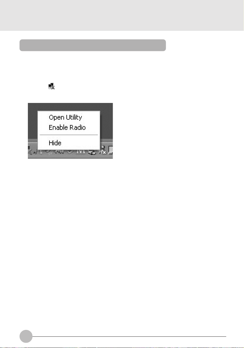
1. Click the icon (Utility) in the notification area appearing in the lower right side of the
screen with the right button of the mouse.
SECTION 1
2. Click “Disable Radio”.
Radio wave of the wireless LAN is turned off.
Critical Points
If “Enable Radio” is clicked when radio wave is off, radio wave transmission is resumed.
41
Page 58
Starting the transmission of radio waves
To communicate using the wireless LAN function, set the personal computer to a status in which it
can transmit radio waves.
1. Switch on the wireless switc h.
2. Click the icon (Utility) in the notification area appearing in the lower right side of the
screen with the right button of the mouse.
3. Click “Enab le Radio”.
In case of the infrastructure connection, the wireless LAN starts radio wave transmission.
In case of the “ad hoc” connection, proceed to the step 4.
4. Restart the personal computer.
42
Page 59

Flow of operations
The wireless LAN connection procedure is outlined below.
1. Make sure that the personal computer is ready f or the transmission of radio waves from
the wireless LAN.
2. Assign the parameters required for wireless LAN connection.
1. Enter the network name (SSID) and other data.
2. Enter the network key (the key to be used to encode communications data).
3. Perform setting operations relating to network connection.
1. Specify TCP/IP as the protocol, and confirm the name of the work group and other settings.
2. Enter the data required for file/printer sharing on the network. Perform this operation as
required.
3. For infrastructure connection, enter data for the station.
4. Verify that you have been able to connect your computer to the network.
SECTION 1
43
Page 60

Preparation for using the wireless LAN
Preparation necessary for using the wireless LAN (parameter setting) is explained below.
IMPORTANT
When connecting with the existing network, confirm details of the setting to the network
administrator.
The wireless LAN (Compliant with IEEE802.11b) used for the LifeBook uses channel-1 to
channel-11 as radio channels.
If it is intended to use the wireless LAN by the infrastructure connection (network through
the station), check the radio channel to use, there is a case that the radio channel of the
station has been set at a channel higher than channel-11 by initial setting or automatic
setting.
If so, reset the radio channel of the station at a channel from channel-1 to channel-11. For
details of channel setting, refer to the manual of the station currently in use.
Critical Points
When using the wireless LAN by the infrastructure connection (network through the station),
refer to the manual of the station for setting of the station.
When setting up a new wireless LAN to connect with other personal computers having the
wireless LAN function by the ad hoc connection, there is no need to set a radio channel
(frequency band), because this PC automatically detects the channel used in the wireless
LAN to connect and performs communication on the detected channel. The initial setting of
the channel is 11.
When you need to change the channel setting, refer to “Setting of channels during ad hoc
connection”
For connecting with the Internet using ADSL (PPPoE) through the infrastructure connection,
it is required to change the MTU size of the personal computer. For details, refer to the
manual of the station.
1. Click the “Start” button and then “Control panel”.
2. Click the “Network Connection”.
3. Click the “Wireless network connection” in the table with the right button of the
mouse, and click the “Pr operties” in the menu that appears on the following tab le.
44
Page 61

4. Click the “Wireless Networks” tab.
(The contents of the screen differ depending
on the model and situation.)
5. Make sure that the “Use Windows to configure my wireless netw ork settings” has
been checked as .
6. Click the “Add” of the “Preferred networks”.
The “Wireless Network Properties” window is shown on the screen.
7. Click the “Association” tab.
SECTION 1
45
Page 62

8. Enter the data for encoding communications data.
In case of the ad hoc connection
1. Input a “Network name (SSID)”.
Input the same network name within 32 letters in condensed type (half-size character)
for all personal computers to be connected.
2. Click the check bo x of the “This is a computer-to-computer (ad hoc) network; wireless
access points are not used” so that it turns into .
In case of the infrastructure connection (network through station)
1. Input a “Network name (SSID)”.
Input a name properly to the station to connect. For setting the station, refer to the
manual of the station.
2. Click the check bo x of the “This is a computer-to computer (ad hoc) network; wireless
access points are not used” so that it turns into .
Next, proceed to setting to encode communication data.
IMPORTANT
It is strongly recommended to set a network key to encode communication data. If no
network key is set, there is a fear that data may be stolen by other users because the
network can be accessed by all personal computers having the wireless LAN function.
9. Click the chec k bo x ( ) of the “Data encryption (WEP enabled)” to turn it into .
In case of the ad hoc connection
Click the check box ( ) of the “Network Authentication (Shared mode)” to turn it into
.
In case of the infrastructure connection
If the connecting station is set for the common key (shared k ey) authentication, click the
check box ( ) of the “Network Authentication (Shared mode)” to turn it into .
In case of the open system authentication, click the check box ( ) to turn it into .
For setting of the station, refer to the manual of the station.
46
Page 63
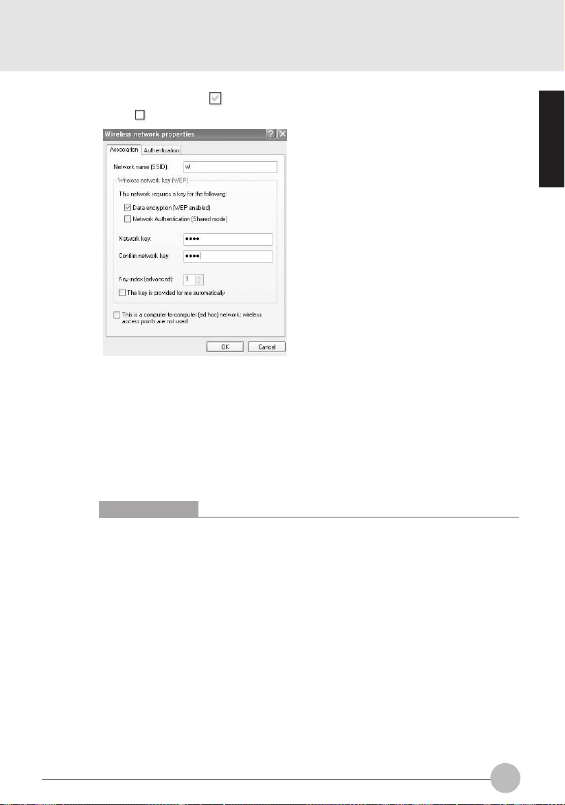
10. Click the check box ( ) of the “The ke y is pro vided f or me automaticall y” to turn
it into .
11. Input a “Network key” properly to the connection system to use.
Key input can be done in two key systems of “ASCII character” and “Hexadecimal
character code”, but it is advised to do it in the “ASCII character” in general.
In case of the ad hoc connection
Set the same value for all personal computers to connect.
In case of the infrastructure connection
Set the key properly to the station to connect.
For setting of the station, refer to the manual of the station.
SECTION 1
Critical Points
If there is any wireless LAN equipment whose network key is set in a hexadecimal
character code in the network, input the hexadecimal character code.
The key system is automatically discriminated by n umber of characters of the input
network key.
Characters (letters and numbers) usable for the “Network key” are as follows.
• In case of the ASCII character key system:
0-9, A-Z, a-z, _ (underscore)
• In case of the hexadecimal character code key system:
0-9, A-F, a-f
Number of characters that can be input as a “Network ke y” diff ers depending on the
network key system, specifications of the wireless LAN equipment to connect.
• In case of the ASCII character key system:
5 characters for 64-bit WEP, or,
13 characters for 128-bit WEP
• In case of the hexadecimal character code key system:
10 digits for 64-bit WEP, or,
26 digits for 128-bit WEP
47
Page 64

12. Input a value for the “Network key”.
Input the same value as the “Network key” input in the preceding step 11. If a different
value is input, setting results in failure.
13. Confirm that the “Key index (Advanced)” is set as “1”.
The “Ke y index (Adv anced)” can be set in maximum f our from “1” to “4”. Set “1” generally .
14. Click the “Authentication” tab and then click the check box of the “Enable
network access control using IEEE802.1X” so that it becomes .
Critical Points
In case of restricting the access of wireless LAN clients using IEEE802.1X
15. Click the “OK”.
48
authentication, put a check mark on “Enable network access control using
IEEE802.1X“. In case of home use, remove a check mark on “Enable network
access control using IEEE802.1X“.
For the method of setting related with IEEE802.1X authentication, refer to the station
manual.
Page 65
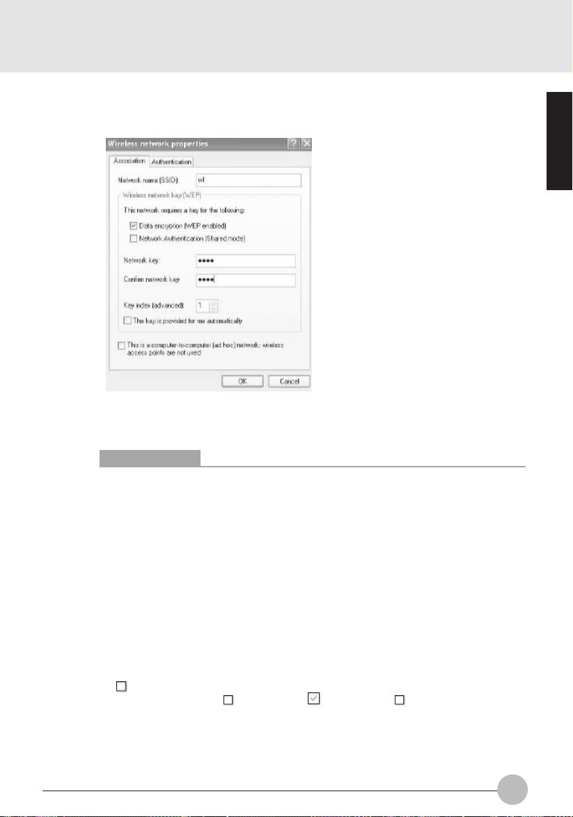
16. Confirm that the network name input as the “Netw ork name (SSID)” by the step 8
is added to the “Preferred networks”.
(The contents of the screen differ depending on the model and situation.)
Critical Points
If there are multiple settings in the “Preferred network”, another setting may have
priority over the desired network because of communication condition. It is
recommended to register only one setting of the desired network to avoid confusion.
SECTION 1
17. Click the “OK”.
18. Click the “Start” button and click “Turn off computer”. Then, click the “Restart” in
the “"Turn off computer” menu.
The personal computer restarts.
19. Click the “Power options” in the “Control panel”.
20. Set the following items and click “OK”.
• Click the “Power Schemes” tab to turn the “System standb y” and " System hibernates
into.
• Click the “Hibernate” tab and make sure that the “Hibernate mode” is not checked
( ).
If the check box is not , click the box ( ) to turn it into .
Then, the personal computer is set not to enter standby mode or hibernate mode
automatically.
Next, proceed to setting up the network.
49
Page 66

SECTION 2
Connection to the Network
This section explains connection to the network.
Setting the network
IMPORTANT
If a cable LAN has been set up, be careful not to compete with the cable LAN setting. If
wireless LAN setting compete against the existing cable LAN setting, the network fails
in normal communication.
During connection with a network (Internet, etc.) using the LAN function, it is advised
not to enter the personal computer into the standby or hibernate mode, because the
personal computer fails in normal connection with a network (Internet, etc.) depending
on the use environment.
When the personal computer is not used, be sure to shut down the system.
When connecting with an existing network, consult with the administrator of the network
about setting in detail.
For connecting with the Internet by ADSL through a station such as an optional wireless
broad-band rooter, etc., refer to the manual of the station and other manuals provided
by the provider and line enterprise for setting.
❑ TCP/IP setting
1. Click the “Start” button and “Control panel”.
2. Click the “Network connection”.
The table of network connections appears on the display.
3. Click the “Wireless Network Connection” appearing in the table by the right b utton of
the mouse, and click the “Properties” in the menu.
4. Click the “Internet protocol (TCP/IP)” in the table of the “This connection uses the
following item”, and then click the “Properties”.
5. Set an IP address.
50
Page 67

In the case there is a DHCP server such as the broad-band rooter , etc. in the station
or network in the infrastructure connection.
1. Make sure that both the “Obtain IP address automatically” and “Obtain address of DNS
server automatically” are marked with .
If those are marked with , click to turn the both into .
In the case there is no DHCP server in the station or network in the ad hoc or
infrastructure connection.
1. Click of the “Use the following IP address” so that it turns into .
2. Input an IP address in the “IP address” box.
Example: 192.168.0.1
3. Input a value in the “Subnet mask” box.
Example: 255.255.255.0
6. Click “OK”.
Next, confirm the full computer name and work group name.
❑ Confirmation of computer name, work group name
Critical Points
For changing the computer name and/or work group name , log in the Windows as the account
of “Administrator of computer” or a member of the “Administrators” group.
1. Click the “Start” button and “Control panel”.
2. Click the “Performance and maintenance”.
3. Click the “System”.
The “System Properties” window appears.
4. Click the “Computer name” tab.
SECTION 1
51
Page 68

5. Confirm the “Computer name” and “W ork group name”. For changing the name, c lick
the “Change” and input a new name.
• Computer name
The computer name is used to identify the computer in the network. Each personal
computer can be named optionally. When naming a computer, input the name within 15
characters (including numeric) of condensed type (half-sized character). It is
recommended to input a name including the model name or user name for easy
discrimination.
• Work group
The name of the network group should be inputted within 15 characters (including
numeric) of condensed type (half-sized character). Generally set personal computers
connected with the same network as those of the same work group.
6. Click “OK”.
If a message to confirm restart of the computer, restart it following instructions on the
screen.
52
Page 69

Setting the sharing function
Set the sharing function to make file and/or printer sharing with other network-connected personal
computers valid.
The setting operation is not required unless the sharing function is to be used.
The folder and printer for which the sharing function has been set will be usable from any personal
computer present on the network.
❑ Setting of Microsoft network service for common use
1. Click the “Start” button and “Control panel” in this order.
2. Click the “Network and Internet connection”.
The table of network connection is shown on the screen.
3. Click the “Wireless network connection” in the table by the right b utton of the mouse,
and then click the “Properties” in the menu shown next.
4. Make sure that there is a check mark ( ) in the check box of the file and printer
sharing for Microsoft network” in the table of “This connection uses the following
item”, and then click the “OK”.
If the check box is , click to turn it into and click the “OK”.
Critical Points
If the “File and printer sharing for Microsoft network” is not shown on the screen, install it
following the procedure mentioned below.
1. Click the “Install”.
The “Select type of network component” window appears on the screen.
2. Click the “Service” in the table and then click the “Add”.
The “Select network service” window appears.
3. Click the “Common use of file and printer for Microsoft network” in the table, and then
click the “OK”.
4. The “File and printer sharing for Microsoft network” is shown in the table of “This connection
uses the following item”. After confirming the check mark for the “File and printer
sharing for Microsoft network”, click the “Close”.
SECTION 1
53
Page 70

❑ Setting for sharing a file
The following explains setting sharing of a “work” folder in the C drive.
1. Click the icon (My computer) on the desktop.
2. Click the “Local disk (C:)”.
3. Click the “work” folder by the right button of the mouse, and click the “sharing and
security” in the menu shown following.
The “Work Properties” window appears.
4. Click the “"Sharing” tab.
The “Effectuate common use of file” window appears.
Critical Points
If the “Click here for using file in common without use of wizard with recognition of risk” is
already clicked, this page is not shown. Proceed to the step 6.
The contents of the “Common use and security in network” are changed.
54
Page 71

5. Click the “Sharing this folder on the network” and then “OK”.
6. Click the check box ( ) of the “Sharing this folder on the network” to turn it into .
Critical Points
For setting the share folder for read only, click the check box ( ) of the “Allow network
users to change my files” to turn it into .
7. Click the “OK”.
The folder is set for sharing, and the icon of the “work” folder turns into .
SECTION 1
55
Page 72

❑ Setting for sharing a printer
1. Click the “Start” button and “Printer and other Hardware”.
The “Printer and other Hardware” window appears.
2. Click the printer to set it for sharing by the right button of the mouse, and click the
“Sharing” in the menu shown following.
3. Click of the “Share this printer” to turn it into .
4. For changing the printer name shown in the “Share name”, input a new printer
name.
5. Click the “OK”.
The printer is set for sharing use and the icon of the printer changes so that it indicates
common use.
56
Page 73

Confirming connection
After you have finished the network setup operations, access the f older whose sharing has been set
for other personal computers. Also, confirm the status of the radio wav es in case of troub le such as
a network connection failure.
Critical Points
In the case of infrastructure connection, enter the necessary data for the station before
confirming connection. Refer to the manual of the station for the station setup procedure.
❑ Connecting your personal computer to another personal computer
1. Click the icon (My computer) on the desktop.
2. Click the “My Networks Places” in the list of others.
SECTION 1
57
Page 74
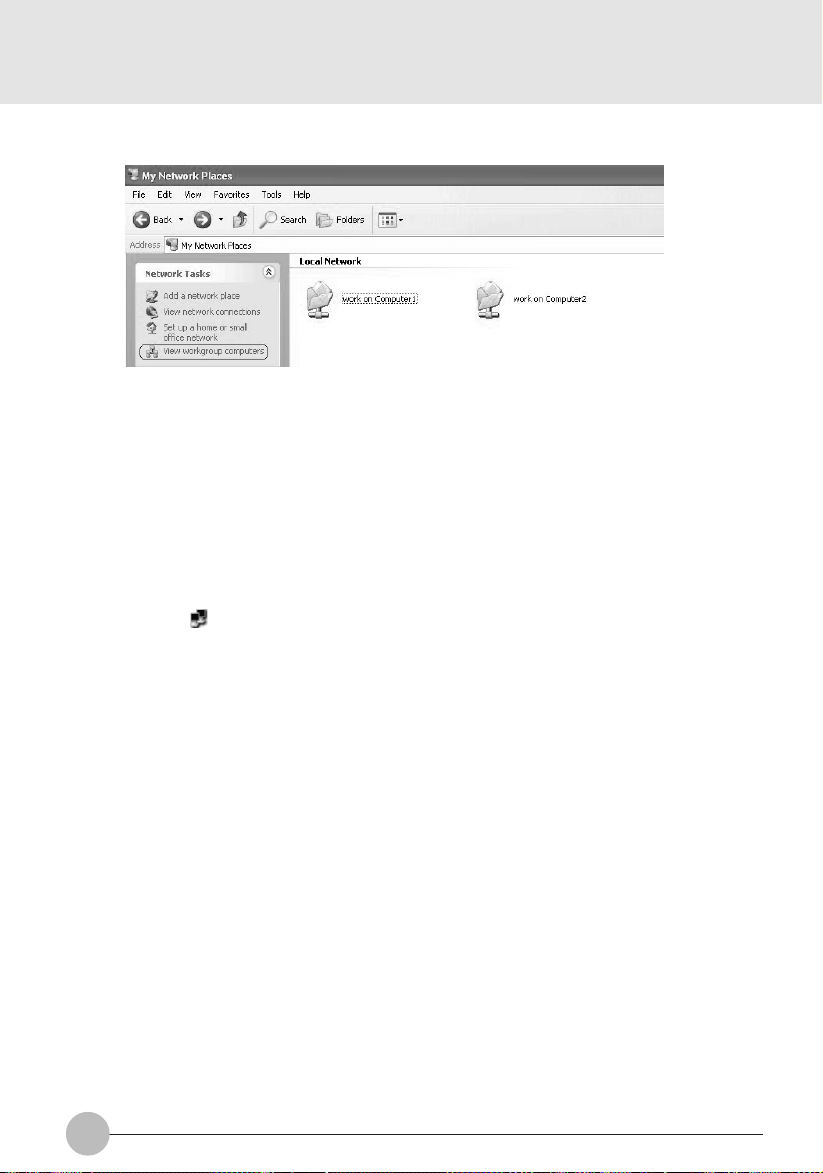
3. Click the “"View workgroup computers” in the list of the Network task.
The table of computers of the work group in which you are joining in is shown.
4. Click the personal computer that is desired to connect.
The folder set in the “Setting of sharing use of personal computers” is shown.
5. Click the folder that is desired to connect.
The contents of the folder are shown and the folder becomes usable.
❑ Check radio wave condition
1. Click the icon (Utility) in the notification area in the lower right of the screen by the
right button of the mouse.
The “Broadcom Wireless Configuration Utility” window appears.
2. Click the “Open Utility”.
The “Broadcom Wireless Configuration Utility” window appears.
58
Page 75

3. Check the radio wave condition on the “Link Status” tab page.
The present connection condition is shown.
When radio wave is turned off or the computer is not yet connected, connection condition is
not shown for some items.
Item
Status (connected • not yet connected
• Disable Radio, etc.)
Network name (SSID)
BSSID
Data encryption (WEP)
Speed (transmission)
Channel
Client IP Address
Network Connection Type
Radio state
Signal
Noise
When you fail in connection with the network or want to confirm the connection, refer to the
“Troubleshooting”.
Comment
Connection condition, radio wave transmission
condition, etc. are shown.
Inputted network name (SSID) is shown.
In the infrastructure connection, the MAC address of
the station currently in connection is shown. In the ad
hoc connection, the value is shown also but it is not the
MAC address of the client in the ad hoc connection.
When the network key is used, “Enabled” appears in
this line. When the network key is not use, “Disabled”
appears.
The present transmission rate is shown in Mbps. No
reception rate is shown.
The channel currently in use for communication is
shown.
The IP address is shown.
“Infrastructure” or “ad hoc” is shown.
When radio wave is outputted, “Enable Radio” appears.
The longer the indication of the bar graph is, the better
the radio wave condition is.
The shorter the indication of the bar graph is, the better
the radio wave condition is under a little influence of
noise.
SECTION 1
59
Page 76

SECTION 1
Appendix
Other settings
Other wireless LAN settings are described.
Setting of channels during ad hoc connection
IMPORTANT
You can set channels during ad hoc connection.
Channel 11 is set by default.
When connecting a personal computer with the existing ad hoc connection, it is required to
change the channel setting to meet the channel in use.
This setting is effective in the ad hoc connection only. In the infrastructure connection, the
channel is automatically set to match to the station.
1. Log on the computer by the account of the computer administrator or as an administrator
or a member of administrators group.
2. Click the icon (My computer) on the desktop and right click on "My computer" and
select properties.
The “System properties” window appears.
3. Click the “Device manager” of the “Hardware” tab.
The “Device manager” window appears.
4. Double c lick the “Broadcom BCM4306 Wireless LAN Adapter” in the “Network controller”.
The “Broadcom BCM4306 Wireless LAN Adapter properties” window appears.
5. Change the channel by the “IBSS Channel Number” of the “Advanced” tab.
6. Click the “OK”.
7. Click and all the windows are closed.
60
Page 77

SECTION 1
Troubleshooting
Causes and countermeasures for troubles you may encounter while using wireless LAN are described.
Refer to the relevant item.
Unavailable connection to the network
• Even if you double-click “Network computer” icon, no other computer will be displayed or no
connection can be established if it is displayed.
• During infrastructure connection, you cannot connect to the station.
➔ “Incorrect network name (SSID) or network key”
➔ “Unmatched “Network authentication (shared mode) settings”
➔ “Incorrect setting of IP address”
➔ “Incorrectly-performed network setting”
➔ “Under the condition of stopped electric wave transmission”
➔ “In case of the LifeBook, the channel set for the station is out of the usable channels for this
PC.”
➔ “Unreachable electric wave due to poor condition of electric wave”
➔ “Active channel duplication due to multiple wireless LAN networks on the same floor, etc.”
➔ “The computer to be connected with is turned OFF.”
➔ “No right of access to the network to be connected with”
➔ “It takes too long to retrieve the network and display the connected computers.”
➔ “The connection is cut off several minutes after the personal computer is connected with the
station.”
SECTION 1
❑ Incorrect network name (SSID) or network key
❍ Countermeasure
In case of ad hoc connection, set the network names (SSIDs) and network keys of all computers to
be connected to the same values. In case of infrastructure connection, set the network name (SSID)
and network key to the same values as those of station. Also , set the network authentication according
to the station.
In case of the Windows XP, setting of the “Network authentication (shared mode)” is different from
others concerned.
❍ Countermeasure
When the setting of the “Network authentication (shared mode)” does not correspond to the station
and personal computer, no communication is performed in the network.
Check the setting referring to the “Preparation for using the wireless LAN”.
61
Page 78

❑ Setting of IP address is not correct.
❍ Countermeasure
Check the setting of the network.
If the protocol in use is TCP/IP, the IP address can be checked by the following procedure.
1. Operate as follows.
• In case of the Windows XP
Click the “Start” button, “All programs”, “Accessory” and “Command prompt”.
2. Input the “IPCONFIG” command on the “Command prompt” page, and press the [Enter] key.
Example: In the case the C drive is the hard disk drive,
C: >ipconfig [Enter]
Check to see if the IP address is normally shown on the screen.
IP Address..........: 10.0.1.3
Subnet Mask..........: 255.255.255.0
Default Gateway..........: 10.0.1.1
When IP address is displayed as “169.254.XXX.YYY” or “0.0.0.0”, IP address is not correctly
fetched from the station. In that case, restart the computer itself. If the displa y is still unchanged,
check the setting of TCP/IP. If “Cable Disconnected” or “Media Disconnected” is display ed without
showing IP address, check the setting of network name (SSID) and network key. Also, set the
network authentication according to the station.
❑ Incorrectly-performed network setting
❍ Countermeasure
Check the protocol, work group name or shared setting.
❑ Under the condition of stopped electric wave transmission
❍ Countermeasure
Check if the wireless switch is turned ON.Also make sure of “Disable Radio” (condition of sending
62
Page 79

❑ The set channel for the station is different from those which can be
used by this computer.
❍ Countermeasure
Set the channel of station within the range of 1~11. F or the method of setting, ref er to the station manual.
❑ Unreachable electric wave due to poor condition of electric wave
❍ Countermeasure
In case of ad hoc connection, retry connection after shortening the distance to the destination computer
or removing any obstacle for better sight. In case of infr astructure connection, retry connection after
shortening the distance to the station or removing any obstacle for better sight.
❑ Active channel duplication due to multiple wireless LAN networks on
the same floor, etc.
❍ Countermeasure
If there is any other wireless LAN network nearby , change channels to av oid active channel duplication.
❑ The computer to be connected with is turned OFF
❍ Countermeasure
Check if the computer to be connected is turned ON.
❑ No right of access to the network to be connected with
❍ Countermeasure
Check if you have a right of access to the network to be connected with.
SECTION 1
63
Page 80

❑ It takes too long to retrieve the network and display the connected
computers
❍ Countermeasure
Retrieve computers in the following procedure:
• In case of the Windows XP
1 Click “Start” button, then click “search”.
2 Click “Computer or people”.
3 Click “Computers on the network”.
4 Input the name of computer to be connected with in “Computer name” and click “search”.
5 Click the icon of connected computer.
❑ Disconnected communication a few minutes after every connection to
the station
❍ Countermeasure
Check the setting of the “Enable network access control using IEEE802.1X”.
Critical Points
In case of restricting the access of wireless LAN clients using IEEE802.1X authentication,
put a check mark on “Enable network access control using IEEE802.1X”. In case of home
use, remove a check mark on “Enable network access control using IEEE802.1X”. For the
method of setting related with IEEE802.1X authentication, refer to the station manual.
❑ Connection check with executed PING command
Check if IP packet has correctly reached the destination by e xecuting PING command in the f ollowing
procedure:
Critical Points
In order to execute PING command, it is necessary to install TCP/IP protocol in advance.
64
Page 81

1. Operate as follows.
• In case of the Windows XP
Click the “Start” button, “All programs”, “Accessory” and “Command prompt”.
2. At command prompt, input ping command as follows:
Example: In case of C drive being a hard disk and IP address being 10.0.1.3
C: >ipconfig [Enter]
If properly connected, the following screen will be displayed:
Pinging 10.0.1.3 with 32 bytes of data:
Reply from 10.0.1.3: bytes=32 time=1ms TTL=32
Reply from 10.0.1.3: bytes=32 time<10ms TTL=32
Reply from 10.0.1.3: bytes=32 time=4ms TTL=32
Reply from 10.0.1.3: bytes=32 time<10ms TTL=32
In case of no connection, “Request timed out” or “Destination host unreachable” will be
displayed. In that case, refer to “Unavailable connection to the network”.
SECTION 1
65
Page 82

66
Page 83

2
This section explains installation of options for
this computer.
SECTION 2SECTION 2
67
Page 84

SECTION 2
1 Connecting a Printer
Preparing what are needed
• Printer
Prepare a printer designed for Windows.
• Printer driver
A driver should be included with your printer.
If several CDs are included with your printer, refer to your printer’ s instruction manual and select
the CD designed for the version of Windows you are using. In some cases, you may download
the latest version of driver from the Web site of your printer manufacturer.
• Printer cable
Used to connect your printer to the computer. Prepare a USB cable that can be plugged into a
USB port of your computer.
• Instruction manual for your printer
Ways to connect and set up printers vary from printer to printer. So be sure to read your printer’ s
instruction manual, too.
Connecting a printer
This section explains how to plug a printer cable into a USB port on your computer.
1. Insert one plug of the printer cable into a USB port on the right side of your computer.
Insert the plug with the face marked with facing to the top.
USB port
2. If this is for the first time your have connected your printer, install the driver.
68
Page 85

SECTION 2
2 Connecting a USB Device
Preparing what are needed
• USB devices
Devices that can be plugged in the USB ports on your computer.
Prepare USB devices that suit your needs.
- Digital camera
- Mouse
- Terminal adapter
- Printer
- Scanner
- Keyboard
• USB cables
Used to connect a USB device to your computer. Some USB devices come standard with a
separate cable, and others, such as mice, come with a cable already connected.
For more information, refer to the documentation included with your USB device.
• USB device drivers
Some USB devices come with CDs or floppy disks containing their respective driv ers. If necessary,
install the driver designed for Windows according to the instructions in y our USB device man ual.
• Instruction manuals for your USB devices
Ways to connect cables vary from device to device.
Before first connecting a USB device to you computer, read its manual carefully.
SECTION 2
IMPORTANT
Your computer can be used with USB1.1- and USB2.0-compliant devices.
Critical Points
Each USB port on your computer is capable of supplying electric power of up to 500 mA to
the USB device connected. For more information, refer to the documentation included with
your USB device.
When connecting two or more PC cards and USB devices at the same time, you should
power your computer from the AC adapter to pre vent the deterioration of the internal battery
pack.
The performance of a USB device connected to your computer varies depending on the
performance of the USB hub and cable used.
69
Page 86

Connecting a USB device
1. Connect a USB cable to your USB device.
2. Plug the cable from the USB device in a USB port on the right side of your computer.
Insert the cable connector with the face marked with facing to the top.
USB port
(Your computer or situation may not look exactly like this illustration.)
3. Install the driver.
Some USB devices can be used simply by connecting to a computer without installing their
drivers. For more information, refer to the documentation included with your USB device.
70
Page 87

SECTION 2
3 Installing Memory
Critical Points
Here are the initial and maximum memory capacities of your computer.
Initial memory capacity Maximum memory capacity
256 MB 768 MB
Preparing what are needed
• Memory (expansion RAM module)
- 1 memory module can be installed.
Installing memory
• When installing or removing memory , be sure to turn off your computer
• Keep small objects, such as covers, caps and screws, out of the
• Certain components around the memory slots become very hot.
• When installing or removing a memor y module, hold it by the edge
• Memory is composed of static-sensitive parts and it is easily broken
• When installing or removing memory , be sure to turn off your computer
SECTION 2
and disconnect the AC adapter to avoid shoc k hazards .
reach of babies and children to avoid the danger of suffocation.
In the event a baby or child has swallowed such an object, consult
the doctor immediately.
T o avoid possib le burns, do not install or remove memory immediately
after turning off the computer but wait for its internal components to
cool down.
so as not to touch any contacts or IC. Also, be careful not to touch
internal components or terminals of the computer. Touching these
parts with oily fingers could result in a poor connection.
by static electricity built up in a human body . Before handling memory ,
always touch an appropriate metal object to discharge static electricity
from your body.
in advance. If you install or remove memory with the computer placed
in standby or hibernation mode, data could become lost or the
computer or memory could be damaged.
71
Page 88

Critical Points
To avoid damage, do not to touch internal components unnecessarily.
To avoid damage, be careful not to drop small parts into your computer.
1. Turn off the computer by sliding the main power switch to the O position, and disconnect
the AC adaptor.
2. If the keyboard is detached, attach it.
3. Close the keyboard.
Fold the tilt feet flat.
4. Raise the LCD panel.
72
Page 89

5. Tip your computer carefully toward you and place it on its LCD panel, as shown in the
figure below.
IMPORTANT
When tipping your computer toward you, do it on a flat desk or the like covered with a soft
cloth. Be careful that the LCD, in particular, does not touch any object with sharp edges or
projections.
When tipping your computer toward you, be especially careful not to giv e an impact to it nor
drop it.
6. Remo ve the screws (2) shown in the figure below , and detac h the expansion RAM module
slot cover.
SECTION 2
Cover
73
Page 90
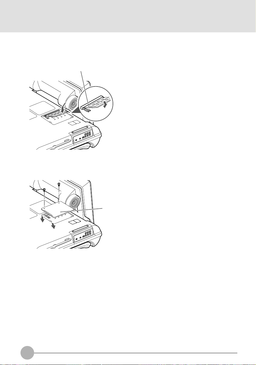
7. Install memory.
Insert the memory diagonally into the slot with the notch in the memory module aligned with the
projection on the connector, and push the memory down until it clicks into place.
Notch in the RAM module
8. Attach the expansion RAM module slot cover and secure it with screws.
Attach the cover removed in step 6.
Cover
74
Page 91

❑ Checking the memory capacity
IMPORTANT
If the memory is not installed correctly, the error message “Expansion memory error” or
another message in English may appear or nothing may be displa yed on your desktop when
you turn on the computer for the first time after installing the memory. If such a case, press
and hold down the power button for 4 seconds or more to turn off your computer, and
remove and reinstall the memory.
1. Turn on the computer.
2. Click the “Start” button and select “Control Panel”.
The “Control Panel” window appears.
3. Click “Performance and Maintenance” and click “System”.
The “System Properties” dialog box appears.
4. Check if the circled numerical value in the figure below has increased by the size of
memory you added.
Memory capacity
SECTION 2
In this example, 256 MB of memory has been installed a computer.
Your system uses 128 MB of memor y as graphic memory (can be adjusted from 16,32,64 and
128MB from BIOS), so that a memory capacity 128MB smaller than the actual memory capacity is
displayed in this window.
The memory capacity displayed may be further 1 MB less than the actual memory capacity, depending
on the system configuration.
75
Page 92

Critical Points
You can change the graphic memory (VRAM) size, using “UMA Video Memory Size” in the
“Advanced menu of BIOS Setup”.
5. Click “OK”.
The “Performance and Maintenance” dialog box appears again.
Critical Points
If the memory capacity displayed is not correct, check if the memory is installed properly.
Changing the memory
1. Turn off the computer by sliding the main power switch to the O position, and disconnect
the AC adopter.
2. If the keyboard is detached, attach it.
3. Close the keyboard.
Fold the tilt feet flat.
4. Raise the LCD panel.
76
Page 93
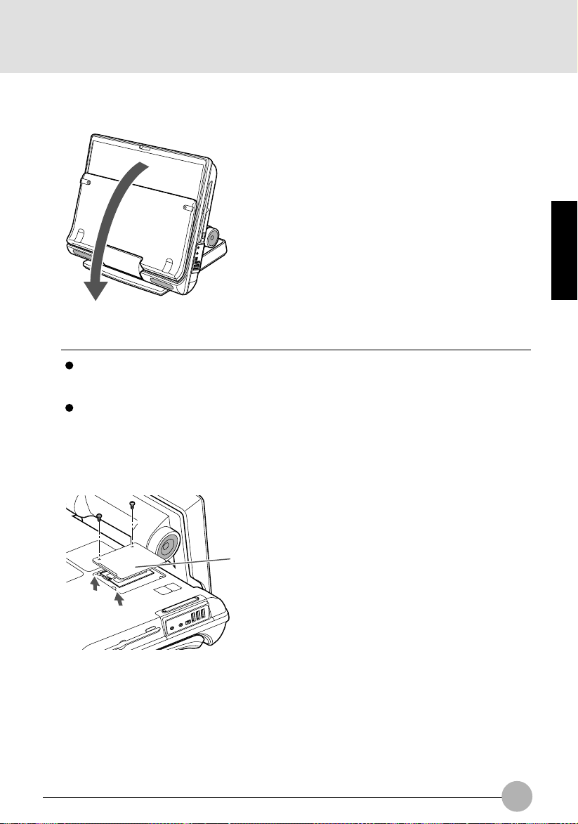
5. Tip your computer carefully toward you and place it on its LCD panel, as shown in the
figure below.
IMPORTANT
When tipping your computer toward you, do it on a flat desk or the like covered with a soft
cloth. Be careful that the LCD, in particular, does not touch any object with sharp edges or
projections.
When tipping your computer toward you, be especially careful not to giv e an impact to it nor
drop it.
6. Remove the screws (2) shown in the figure below, and detach the expansion RAM
module slot cover.
SECTION 2
Cover
77
Page 94

7. Remove the memory.
Undo the hooks on both sides that secure the memory module. The memory raises itself
slightly. Then pull the memory diagonally upward to remove it from the slot.
Tab
8. Install a new memory module.
Insert the memory diagonally into the slot with the notch in the memory module aligned with
the projection on the connector, and push the memory down until it clicks into place.
Notch in the RAM module
78
Page 95
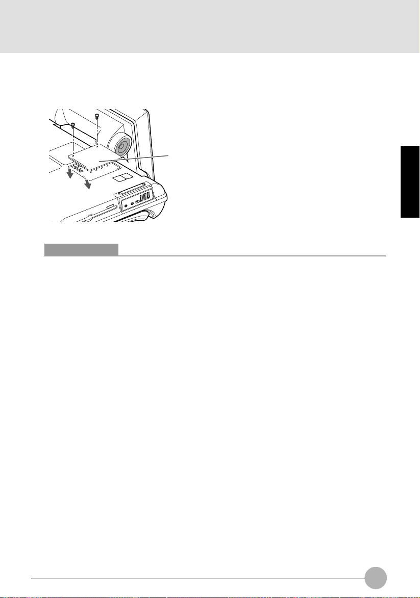
9. Attach the expansion RAM module slot cover and secure it with screws.
Attach the cover removed in step 6.
Cover
Critical Points
After changing memory, check the memory capacity of your computer to be sure that the
memory is installed correctly.
SECTION 2
79
Page 96

80
Page 97

3
This section explains what to do when trouble occurs
with this computer and when messages are displayed.
Read this section as the necessity arises.
SECTION 3
81
Page 98

SECTION 3
1 When This Happens
When you are having trouble with this computer, there is something you think is strange, or
there is something you want to do, but do not kno w ho w . This section is divided into related
items.
❑ The power does not come on.
Checkpoint
Is the AC adaptor connected?
Is the main switch switched
on?
Is the battery charged?
Has the computer been left
unused for a long time?
When using this computer for the first time after purchase, the
battery is not yet charged, so you must connect the AC adaptor
and switch on the main switch.
If the main switch is not switched on, the power will not come on
even if the SUS/RES switch is pressed.
If a beep is heard when the main switch is turned on, then the
battery is running low (LOW BATTERY). Connect the AC
adaptor.
When using the computer for the first time after leaving it
unused for a long time, connect the AC adaptor and switch on
the main switch to switch on the power.
❑ Nothing displayed on the LCD panel
Checkpoint
Is anything displayed on the
status indicator LCD?
Is displayed on the LCD
panel?
Connect the AC adaptor and switch on the main switch.
• Displayed
Adjust the brightness and darkness with the brightness and
contrast controls.
• Flashing
Press the SUS/RES switch to put the computer into operating
mode.
• When the icon is off on the status indicator LCD.
When the computer runs by the battery power, check the
battery status if it is sufficiently charged for operation or not.
If it is not charged, connect the AC adaptor and charge it.
If you are already using this computer with the AC adaptor
connected, check that it is correctly plugged into the power
socket and into the computer.
Cause and Solution
Cause and Solution
82
Page 99

Checkpoint
Have you been pressing any
of the keys?
Is it set to output to the CRT?
❑ LCD panel hard to read.
Checkpoint
Did you adjust the
brightness?
❑ Battery is not charged.
Checkpoint
Is the AC adaptor connected?
Is the battery overheated
(The on the LCD
display flashes.)?
Is the computer too cold
(The on the LCD
display flashes.)?
Was the charging stopped
midway?
Cause and Solution
On this computer, if the power management functions are set
and no key is pressed for a certain period of time, the CPU
stops and the LCD panel backlight goes out. (In this state,
pressing any key lights up the backlight again.) If the computer
stops too frequently, change the BIOS setup settings.
Switch over to the LCD display with the [Fn] + [F10] keys.
Cause and Solution
Adjust the luminance of the LCD’s backlight with the [Fn] + [F6]
keys or [Fn] + [F7] keys on the keyboard.
Cause and Solution
Check that the AC adaptor is correctly plugged into the power
socket and into the computer .
If the ambient temperature is high and the battery temperature
becomes too high during use, the battery protection function
may be triggered to stop the charging.
If the battery temperature falls too low, the battery protection
function may be triggered to stop the charging.
If you use the computer and disconnect the AC adaptor
between the start of charging and the time the LCD turns
off, the battery will not become fully charged, Once you start
charging do not remove the AC adapter until the LCD turns
off.
SECTION 3
❑ The remaining battery charge indicator does not stop flashing.
Checkpoint
Is the battery connected
correctly?
Is the battery low?
Check that the battery is connected correctly. If it is connected
correctly, there is an abnormality in the battery pack, so replace
the battery pack.
Attach the AC adaptor and charge the battery.
Cause and Solution
83
Page 100

❑ No sound or minimal sound from speaker.
Checkpoint
Is the volume control
correctly adjusted?
Turn the volume control to adjust the volume to a proper level. If
volume adjustment with the volume control results in failure,
check to see if the sound driver is correctly installed.
❑ Can not record from Mic or Line In jack.
Checkpoint
Is the volume adjusted
properly?
Turn the volume control to obtain the correct volume. If the line
jack is connected to the sound source, then check that connection. If recording still results in failure after the above-mentioned
operation and check, activate the item “Recording” of the
“Volume Control” and again adjust the volume with it.
❑ LCD panel does not close.
Checkpoint
Is something caught in the
LCD panel?
Forcing the LCD panel closed can damage it. Check for
something caught in the LCD panel. Also, a metal object such
as a paper clip can cause a breakdown if it gets caught in
between the keys.
Cause and Solution
Cause and Solution
Cause and Solution
84
 Loading...