

Page 1

System
Operating Manual
CELSIUS H710
Page 2

Congratulations, you have
decided to buy an
innovative Fujitsu product.
The latest information about our products, useful tips, updates etc. is available
from our website: "
http://ts.fujitsu.com"
For automatic driver updates, go to: "http:// support.ts.fujitsu .com/com/supp ort/index.html"
Should you have any technical questions, please contact:
• our Hotline/Service Desk (see Service Desk list or visit:
"
http://ts.fujitsu.com/support/servicedesk.html" )
• Your sales partner
• Your sales office
We hope you really enjoy using your new Fujitsu system.
Page 3

Page 4

Copyright
Fujitsu Tec
hnology Solutions 05/2011
Published by
Fujitsu Technology Solutions GmbH
Mies-van-
der-Rohe-Straße 8 (Mies-van-der-Rohe Street No. 8)
80807 Munich, Germany
Contact
h
ttp://t
s.fujitsu.com/support
All rights reserved, including intellectual property rights. Subject to technical alterations. Delive ry subject to availability.
No warranty is offered or liability accepted in regard of the completeness, correctness, or current applicability of any
data or
illustrations. Brand names may be protected trademarks of the respective manufacturer and/or protected
by copyright. Use of these by third parties for their own purposes may constitute an infringement o f the holders’
rights. Further information can be found at "
http://ts.fujitsu.com/terms_of_use.html"
Order No. Fujitsu Technology Solutions Gm bH: A26391-K323-Z320-1-7619, edition 2
Page 5

CELSIUS H710
Operating Manual
Innovative technology 7
Ports and operating elements 9
Important notes 12
First-time setup of your device 15
Working with the notebook 18
Security functions 54
Connecting external devices 62
Removing and installing components
during servicing 68
Settings in BIOS Setup Utility 73
Troubleshooting and tips 75
Technical data 82
Manufacturer’s notes 85
Index 92
Page 6

Microsoft, MS, Windows XP and Windows 7 are registered trademarks of the Microsoft Corporation.
Adobe Reader is a trademark of Adobe Systems Incorporated.
MultiMediaCard is a registered trademark of Infineon Technologies AG
Sony and Memory Stick are registered trademarks of Sony Electronics, Inc.
All other trademarks referenced are trademarks or registe red trademarks of their
respective owners, whose protected rights are acknowledged.
Copyright © Fujitsu Technology Solutions GmbH 2011
All rights reserved, including rights of translation, reproduction by printing, copying
or similar methods, in part or in whole.
In the event of violations, perpetrators will be liable to prosecution for damages.
All rights reserved, including rights created by patent grant or registration of a utility model or design.
Subject to availability and tech nical modifications.
Page 7

Contents
Contents
Innovativetechnology ................................................................. 7
Furtherinformation ...................................................................... 7
Notational co nventions .................................................................. 8
Ports and operating elemen
ts ..........................................................
9
Importantnotes ........................................................................ 12
Safetynotes ............................................................................ 12
Additional safety notes for devices with radio components . . . . . ............................. 12
Energysaving .......................................................................... 13
Energy saving under W indows ....................................................... 13
Travelling with yournotebook ............................................................ 13
Before youtravel ................................................................... 13
Notebook: transporting ............................................................... 14
Cleaning thenotebook .................................................................. 14
First-time setup o
fyourdevice .........................................................
15
Unpacking and che
cking thedevice ......................................................
15
Selectingalocat
ion .....................................................................
16
Mains adapter con
necting ...............................................................
16
Switchingonthe
device for the first time ..................................................
17
Workingwith thenotebook ............................................................ 18
Status indicators ........................................................................ 18
Switching on the notebook . . . . ........................................................... 21
Notebook: switch ing off .................................................................. 21
Keyboard ............................................................................... 22
Virtualnumerickeypad .............................................................. 24
Key combinations ................................................................... 24
Country and keyboard settings ....................................................... 26
Application keys ........................................................................ 26
Programming the application keys .................................................... 27
Touchpadand touchpad buttons .......................................................... 28
Moving thepointer .................................................................. 28
Selecting an item .................................................................... 28
Executing commands . . . . . ........................................................... 28
Dragging items ...................................................................... 29
LCD screen ............................................................................ 29
Webcam ............................................................................... 30
Rechargeablebattery ................................................................... 31
Charging, caring for andmaintaining the battery ....................................... 31
Removing andinstalling the battery ................................................... 31
Module ................................................................................. 33
Removing a module . . . . . . ........................................................... 34
Installing a module .................................................................. 35
Optical drive ............................................................................ 35
Handling data carriers ............................................................... 35
CD/DVD indicator ................................................................... 36
Inserting or removing adata carrier ................................................... 36
Manual removal (emergency removal) . . . . ............................................ 37
Removing and fittingthe dust removalcover(ventilation slotcover) ......................... 37
Using the power-management features ................................................... 39
Fujitsu Technology Solutions 3
Page 8

Contents
Memory cards .......................................................................... 40
Supported formats .................................................................. 40
Inserting the memory card ........................................................... 40
Removing thememory card .......................................................... 41
PC cardsand ExpressCards ............................................................. 41
Inserting the card ................................................................... 42
Removing thecard .................................................................. 43
Loudspeakers and microphones . . ........................................................ 43
Integrated 56k modem . . ................................................................ 44
Connecting notebook modem to telephone wall socket . . . .............................. 45
SIM card ............................................................................... 46
Inserting the SIM card ............................................................... 46
Removing aSIM card ............................................................... 46
Wireless LAN/ Bluetooth (device-dependent) / UMTS (device-dependent) ................... 47
Switching the wireless com ponents on and off ......................................... 47
Setting upWLAN access ............................................................ 48
Access via UMTS ................................................................... 48
Ethernet and LAN ....................................................................... 48
Your Port Replicator (optional) . . . ........................................................ 49
Ports onthe Port Replicator .......................................................... 49
Connecting the notebook to the Port Replicator . . . . . .................................. 50
Connecting the mains adapter to the Port Replicator . .................................. 52
Switching on the notebook via the port replicator . . . . . .................................. 52
Switching off notebookvia PortReplicator ............................................. 52
Disconnecting the notebook from the Port Replicator .................................. 53
Securityfunctions ..................................................................... 54
Configuring the fingerprint sensor ........................................................ 54
Using the Security Lock ................................................................. 55
Configuring password protection inBIOS SetupUtility ...................................... 55
Protecting BIOS Setup Utility (supervisor and user password) . .......................... 55
Password protection for booting of the operating system . .............................. 56
Password protection forthe hard disk ..................................................... 57
Activatinghard diskprotection ........................................................ 57
Deactivatinghard disk protection ..................................................... 58
Boot from Removable Media ............................................................ 58
Owner Information (device-dependent) . . . ................................................. 59
Virus Warning (device-dependent) . . . . . . ................................................. 59
SmartCard reader ....................................................................... 60
Inserting the SmartCard ............................................................. 60
Trusted Platform Module (TPM) (device-dependent) . . . . . .................................. 61
Enabling TPM ....................................................................... 61
Disabling TPM ...................................................................... 61
Connectingexternaldevices ........................................................... 62
Connecting an external monitor . . ........................................................ 63
Connecting external devices to the parallel or serial port . .................................. 64
Port settings ........................................................................ 64
Device drivers ...................................................................... 64
Connecting USB devices ................................................................ 65
Connecting an external SATA hard disk (eSATA) . . . . . .................................. 66
Safe removal ofeSATAand USBdevices ............................................. 66
Connecting external audio devices . . . . . . ................................................. 67
Microphone port/Line In . . ............................................................ 67
4 Fujitsu Technology Solutions
Page 9

Contents
Headphone port . . . .................................................................. 67
Removing and installing components during servicing ... . ............................. 68
Notes oninstalling and removing boards andcomponents .................................. 68
Preparing to remove components . ....................................................... 69
Installing and removing memory expansion . . . . ............................................ 69
Removing acover ................................................................... 70
Removing memorymodules .......................................................... 70
Installinga memorymodule .......................................................... 71
Attaching the cover .................................................................. 71
Finishing component removal . ........................................................... 72
Settings in BIOS Setup Utility . . ........................................................ 73
Starting the BIOS SetupUtility ........................................................... 73
Operating BIOS Setup Utility ............................................................. 73
Exiting BIOSSetup Utility ................................................................ 74
Exit Saving Changes - save changes and exit BIOS Setup Utility . . ..................... 74
Exit Discarding Changes – Discard changes an d exit BIOS Setup Utility . . . .............. 74
Load Setup Defaults – Copy Standard Entries . ........................................ 74
Discard Changes – Discard changes without exiting the BIOS Setup Utility . .............. 74
Save Changes - save changes without exiting the BIOS Setup Utility . . . . . . .............. 74
Save Changes and Power O ff ....................................................... 74
Troubleshootingandtips .............................................................. 75
Help ifproblemsoccur ................................................................... 75
Restoring the hard disk contents under Windows . . ........................................ 76
The notebook’s date or time is incorrect ................................................... 76
When certain characters are entered on the keyboard, only numerals arewritten ............. 76
The notebook’s LCD screen remains blank . . . . ............................................ 77
The LCD screen is difficultto read ........................................................ 77
The external monitorremainsblank ...................................................... 77
The external monitoris blank orthe imageis unstable ..................................... 78
The notebook cannot be started . . . ....................................................... 78
The notebook stops working . . ........................................................... 79
The printer does not print . . . . . ........................................................... 79
The radio connection to a network does not work . . ........................................ 79
Acoustic warnings ....................................................................... 80
Error messages on the screen ........................................................... 80
Technicaldata ......................................................................... 82
Notebook . . ............................................................................. 82
Rechargeablebattery ................................................................... 83
Mains adapter 120W . . .................................................................. 83
PortReplicator (optional) ................................................................ 84
Manufacturer’snotes .................................................................. 85
EnergyStar ............................................................................ 85
Disposal andrecycling .................................................................. 85
Declarationsof Conformity ............................................................... 85
CEmarking ............................................................................ 86
Regulatory notices ...................................................................... 86
Regulatory information for notebooks without radio device . ............................. 86
DOC (Industry CANADA)notices ..................................................... 88
FCC regulatory information for notebooks with radio device ............................. 90
Fujitsu Technology Solutions 5
Page 10

Contents
Index .................................................................................. 92
6 Fujitsu Technology Solutions
Page 11
Innovative technology
Innovative technology
... and ergonomic design make your device a reliable and convenient companion.
The device boots very quickly, is ready for immediate use and offers a particularly
long operating time because of its high capacity battery.
With the user-friendly "BIOS Setup Utility" you can control yo ur no tebook’s hardware and better
protect your system against unauthorised access by using the powerful password properties.
Information on the connections and user components of your notebook can
be found in "
Ports and operating elements", Page 9.
Further information
The Windows drivers for your device can be found on our Internet site.
The factory installation of your device does not support any other operating
system. F ujitsu Technology Solutions accepts no liability whatsoever
if any other operating system is used.
Software oriented components of these instructions refer to Microsoft products,
if they come within the scope of the delivery.
If you install other software products, pay attention to the operating
instructions of the manufacturer.
Fujitsu Technology Solutions 7
Page 12
Innovative technology
Notational conventions
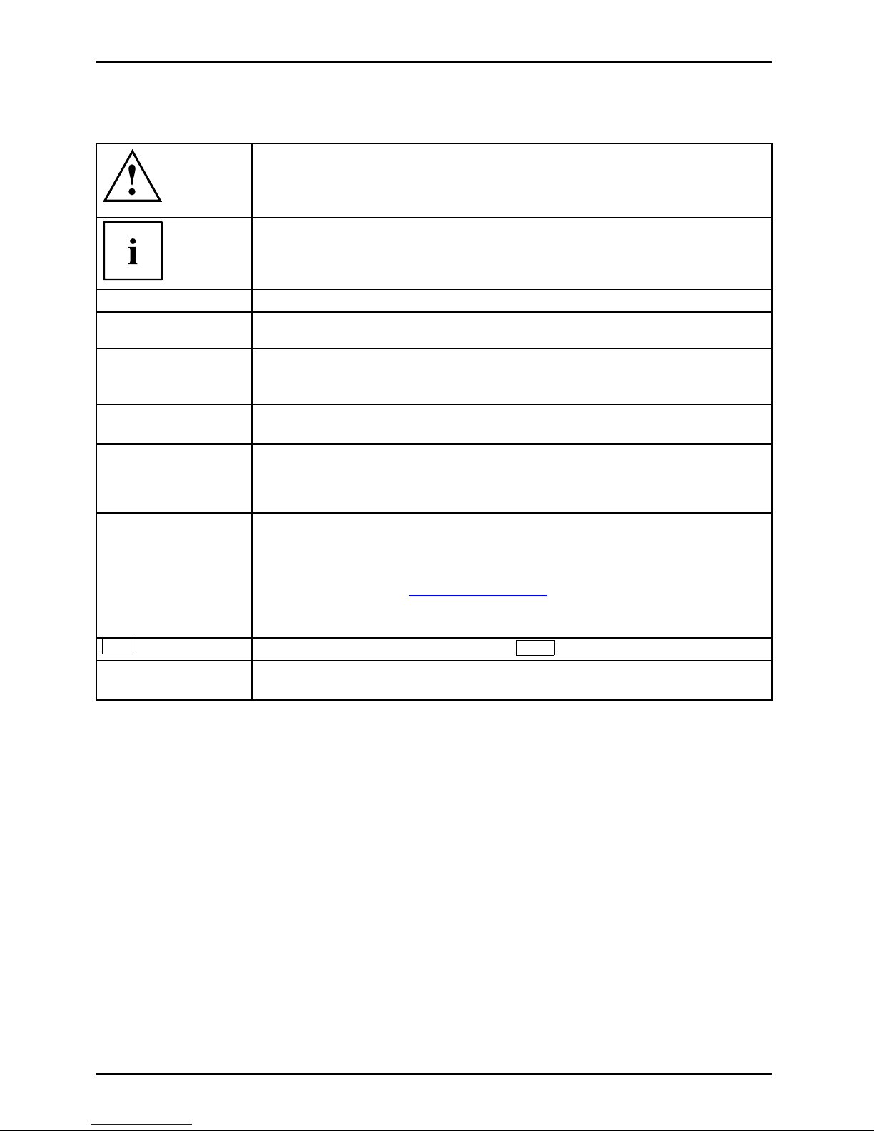
Pay particular attention to text marked with this symbol. Failure to observe
these warnings could p ose a risk to health, damage the device or lead
to loss of data. The warranty will be invalidated if the device becomes
defective through failure to observe these warnings.
Indicates importan t informa
tion for the proper use of the device.
►
Indicates an activity that must be performed
Indicates a result
This font
indicates data entered
using the keyboard in a program dialogue or at
the c ommand line, e.g.
your password (Name123) or a command used to
start a program (star
t.exe)
This font
indicates information that is displayed on the screen by a p rogram, e.g.:
Installation is complete.
This font
Indicates
• terms an d texts used in a software interface, e.g.: Click on Save
• names of programs or files, e.g. Windows or setup.exe.
"This font"
Indicates
• cross-references to another section, e.g. "Safety information"
• cross-references to an external source, e.g. a web address: For more
information, go to "
http://ts.fujitsu.com"
• Names of CDs, DVDs and titles or designations for other materials,
e.g.: "CD/DVD Drivers & Utilities" or "Sa fety/Regulations" manual
Key
indicates a key on the keyboard, e.g:
F10
This font
indicates terms and texts that are emphasised or highlighted, e.g.: Do
not switch off the device
8 Fujitsu Technology Solutions
Page 13
Ports and operating elements
Ports and operating elements
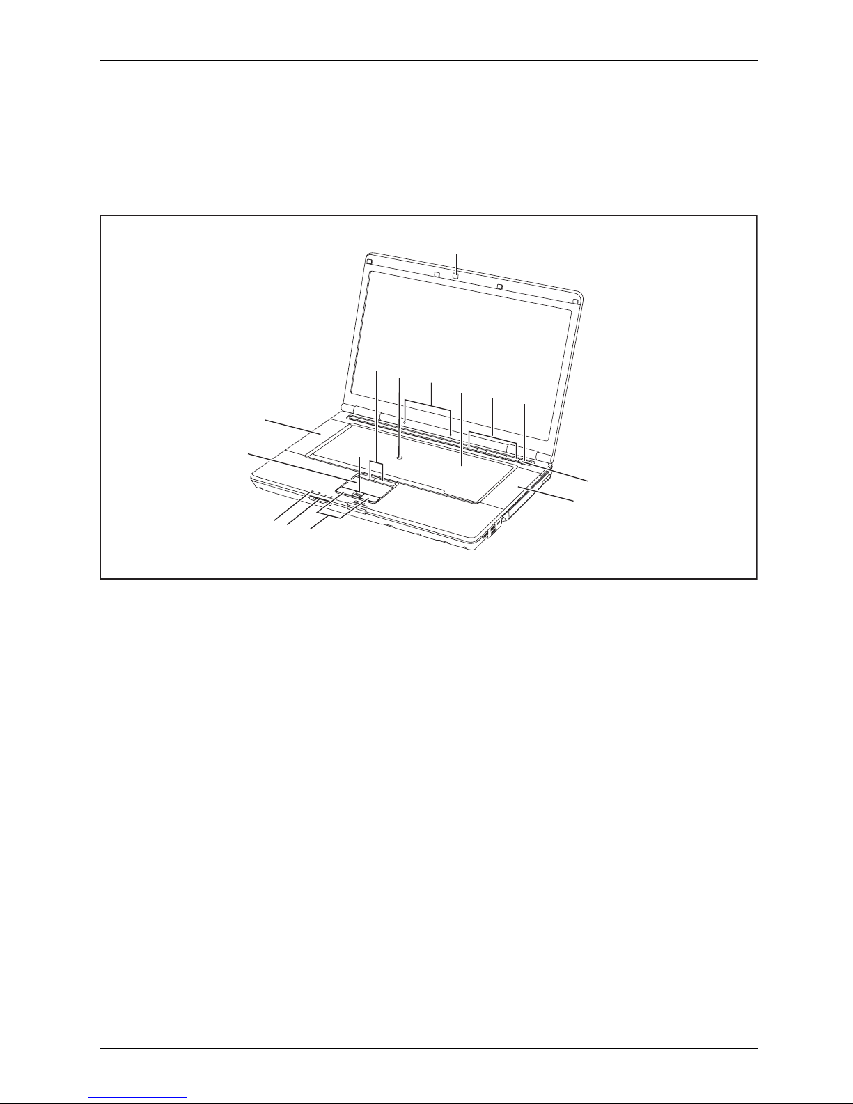
This chapter presents the individual hardware components of your device. It gives
an overview of the indicators and ports of the device. Please familiarise yourself with
these components before you start to work with the device.
6
7
8
5
12
1
13
9
11
10
8
3
2
4
14
1 = WebCam (can be ordered as an option)
2=TouchStick
buttons
3 = TouchStick (can be ordered as an option)
4 = Microphon
es
5 = Keyboard
6 = Applicat
ion buttons
7 = ON/OFF switch
8 = Loudspe
akers
9 = Fingerprint sensor (can be ordered
as an option)
10 = Touchpad bu
ttons
11 = Memory card slot
12 = Status in
dicators
13 = Touchpad
14 = Status in
dicators
Fujitsu Technology Solutions 9
Page 14
Ports and operating element s
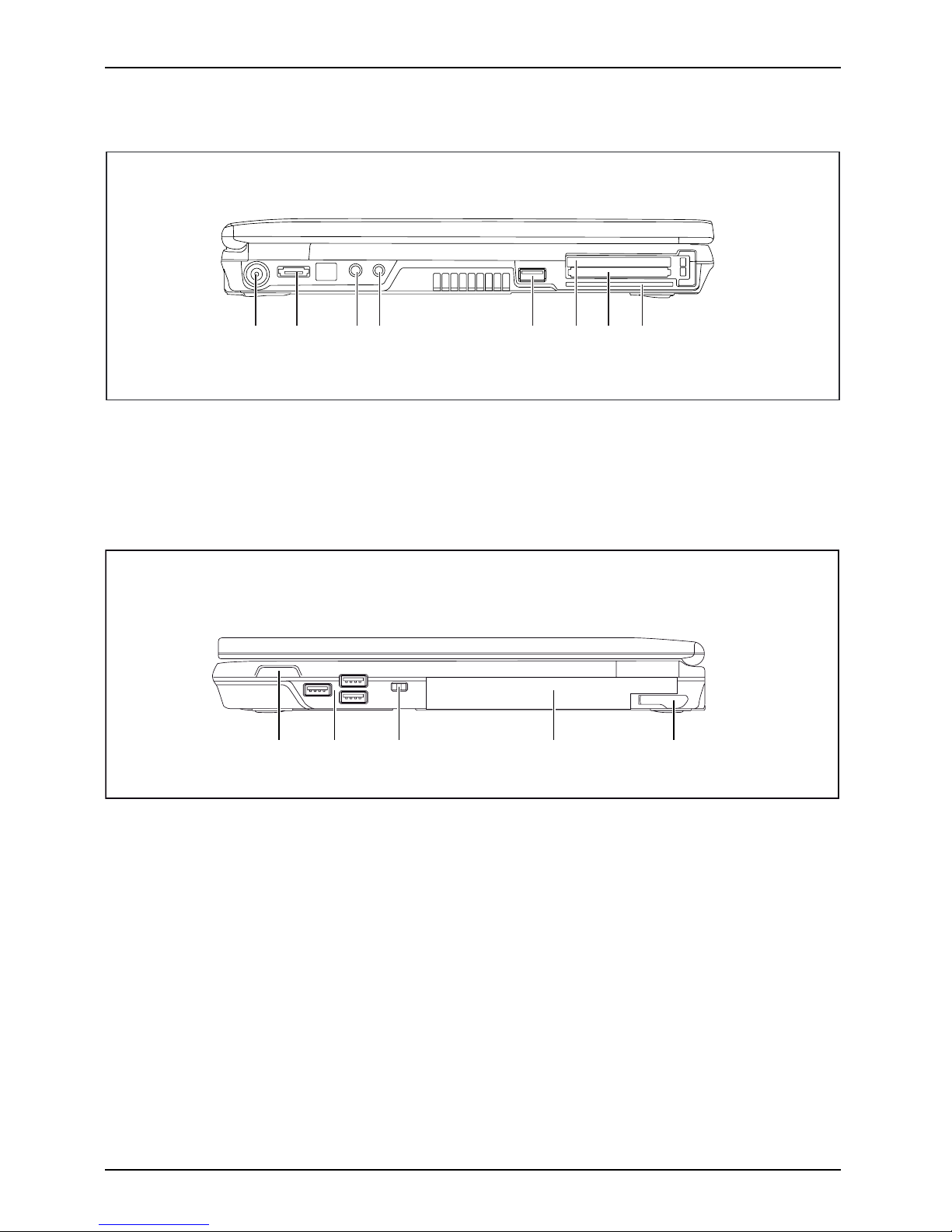
Left panel
1 2 3 4 5 6 7 8
1 = DC input connector (
DC IN)
2 = eSATA port
3 = Microphone port
4 = Headphone port
5 = USB port (USB 3.0)
6 = ExpressCard slot
7 = PC card slots
8 = SmartCard reader
Right side
21 3 4 5
1=ON
/OFF switch for radio components
2 = USB ports
3=K
ensington Lock
4=Mo
dule bay with optical drive
5 = Eject lever for module
10 Fujitsu Technology Solutions
Page 15
Ports and operating elements
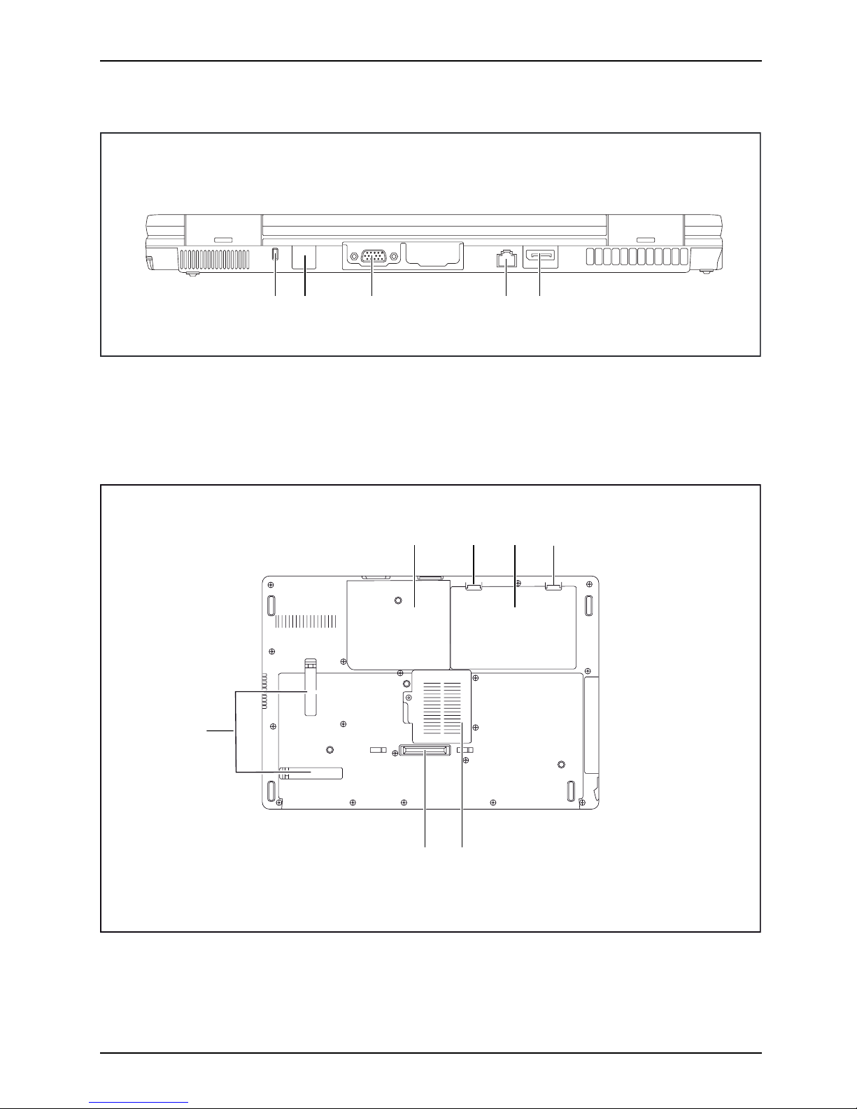
Rear
13 452
1 = Kensington Lock
2 = Modem connection (can be ordered
as an option)
3 = VGA monitor port
4 = LAN port
5 = Display port
Underside
1
3
4
5
6
2
2
1 = Hard disk service compartment
2 = Battery lock
3 = Rechargeable battery
4 = Memory service compartment
5 = Port for port replicator
6 = Ventilation slot cover
Fujitsu Technology Solutions 11
Page 16

Important notes
Important notes
ImportantnotesNotes
This chapter contains essential safety information which must be followed
when wo rking with you r notebook. Other notes also provide useful information
which will help you with your notebook.
Safety notes
SafetynotesNotes
Please follow the safety notes provided in the "Safety/Regulations" manual
as well as the safety notes given below.
Please pay special attention to the sections in the manual marked
with the symbol on the left.
When connecting and disconnecting cables, observe the relevant
notes in this operating manual.
Read the information on the ambient conditions in the "
Technical data",
Page 82 and "First-time setup of your device", Page 15 before preparing your
notebook for use and switching it on for the first time.
When cleaning the device, please observe the relevant notes in the
section "
Cleaning the notebook", Page 14.
Pay attention to the additional safety notes for devices with radio components
provided in the "Safety/Regulations" manual.
Please refer to the notes in the chapter "
Removing and insta lling
components during servicing", Page 68.
This notebook
complies with the relevant safety regulations for data processing
equipment. I
f you have questions about using your notebook in a particular area,
please conta
ct your sales outlet or our Ho tline/Service Desk.
Additional safety notes for devices with
radio components
Radiocomponent:WirelessLAN:Bluetooth,safetynotes
If a radio component (W ireless LAN, Bluetooth, UMTS) is integrated in your notebook, you
must be sure to observe the following safety notes when using your notebook:
• Switch off the radio components when you are in an aircraft or driving in a car.
• Switch off the radio components when you are in a hospital, an operating r oom or near a m edical
electronics system. The transmitted radio waves can impair the operation of medical devices.
• Switch off the radio components when you let the device get near flammable
gases or into hazardous environments (e.g. petrol station, paintshops), as the
transmitted radio waves can cause an explosion or a fire.
For information on how to switch radio components on and off, see chapter
"
Switching the wireless components on and off", Page 47.
12 Fujitsu Technology Solutions
Page 17
Important notes
Energy saving
NotesEnergyEnergysaving
Switch the notebook off when it is not in use. Switch off external, connected devices if you
are not using t hem. If you use the energy saving functions, the notebook uses less energy.
You will then be able to work for longer before having to recharge the battery.
Energy efficiency is increased and the environmental impact is reduced.
You save money while protecting the environment.
Energy saving under Windows
► Make use of the powe r management features (see ""Using t he power-manag ement features",
Page 39").
Travelling with you
r notebook
MobileoperationNotesTransportati onNotebook
Please observe the points listed below when travelling with your notebo ok.
Before you travel
► Back up important data stored on your hard disk.
NotebookTravel,notebook
► Switch off the radio component for data security r easons. With data traffic via a wireless
connection, it is also possible for unauthorised third parties to receive data.
Information on activating data encryption is provided in the documentation
for your radio component.
► If you wish to use your notebook during a flight, first check with the flight
attendants if it is OK t o do so.
When travelling in other countries
► If you are travelling abroad , check that the mains adapter can be operated with the
local mains voltage. If this is not the case, obtain the appropriate mains adapter for
your notebook. Do not use any other voltage converter!
► Check whether the local mains voltage and the power cable are compatible. If this is
not the case, buy a pow er cable that m atches the local conditions.
► Enquire with the corresponding government office of the country you will be
travelling in as to whether you may operate the radio component integrated in
your notebook there (see also "
CE marking", Page 86).
Fujitsu Technology Solutions 13
Page 18
Important notes
Notebook: transporting
Protect the notebook from severe shocks and extreme temperatures
(e.g. direct sunlight in a car).
► If your device has a n optical drive, remove all data media (e.g. CD, DVD) from the drives.
TransportationNotebook
► Switch the notebook off.
► Unplug the mains adap ter and all external devices from the powe r socket.
► Disconnect the mains adapter cable and the data cables for all external devices.
► Close the LCD screen.
► To protect against damaging jolts and bumps, use a notebook carrying
case to transport your notebook.
Cleaning the notebo
ok
Do not clean any interior parts yourself; leave this job to a se rvice technician.
Only use cleaning products designed for comp uters. Normal household
cleaners and polishes can damage the markings on the keyboard and the
device, the paintwork or the notebook itself.
Ensure that no liquid enters the notebook.
The LCD screen very sensitive to scratches. Only clean the display
surface with a very soft, slightly damp cloth.
► Switch the notebook off.
CleaningNotesNotebookKeyboardTouchpadLCDscreenCr ystalView
display
► In order to prevent accidentially switch ing the device o n, remove the power cable from the mains
adaptor and remove the battery (see "
Removing and installing the battery", Page 31).
The surface c
an be cleaned with a dry cloth. If particularly dirty, use a cloth which has
been moiste
ned in mild domestic detergent and then carefully wrung out.
To clean the keyboard and the touchpad, if available, you can use disinfectant wipes.
Ensure that no liquid enters the device.
14 Fujitsu Technology Solutions
Page 19
First-time setup of your device
First-time setup of your devic
e
First-timese tupGettingstarted
Please read the chapter "Important not es", Page 12.
If your device is equipped with a Windows operating system, the necessary
hardware drivers and supplied software are already pre-installed.
Beforeyouswitchonthedeviceforthefirst time, connect it to the mains voltage
using the mains adapter, see "
Mains adapter con necting", Page 16.Themains
adapter m ust be connected during the entire installation process.
A system test is performed when your device is first switche d on. Various messages
can appear. The display may remain dark for a short time or may flicker.
Please follow the instructions on the screen.
NEVER switch off your device during the first-time setup process.
On delivery, the battery can be found in the battery compartment or in the accessories kit.
The battery must be charged if you want to operate your device using the battery.
When used on the move, the built-in battery provides the device w ith the necessary power. You
can increase the operating time by using the available energy-saving functions.
For instructions on how to connect external devices (e.g. m ouse, printer) to your
device, please refer to the operating manual for your device.
Unpacking and
checking the device
Should you discover any damage that occurred during transportation,
notify your local sales outlet immediately!
► Unpack all the individual parts.
PackagingTransport
► Check your
device for any visible damage which may have occurred during transportation.
You ma y n e
ed the packaging in the future, if you need to transport your device.
Fujitsu Technology Solutions 15
Page 20
First-time setup of your device
Selecting a location
SelectingalocationDeviceMainsadapter
Select a s uitable location for the device before setting it up. Follow
the instructions below when doing so:
• Never place the device or the mains adapter on a heat-sensitive surface.
The surface could be damaged as a result.
• Never place the device on a soft surface (e.g. carpeting, upholstered furniture,
bed). This can block the air vents and cause overheating and damage.
• The underside of the device heats up during normal operation. Prolonged contact
with the skin may become unpleasant or even result in burns.
• Place the device on a stable, flat, non-slippery surface. Please note that the
rubber feet of the device may mark certain types of delicate surfaces.
• Keep other objects at least 100 mm away from the device and its
mains adapter to ensure a dequate ventilation.
• Never cover the ventilation slots of the device.
• Do not expose the device to extreme environmental conditions. Protect
the device from dust, humidity, and heat.
Mains adapter connecting
PreparingforoperationMainsadapter
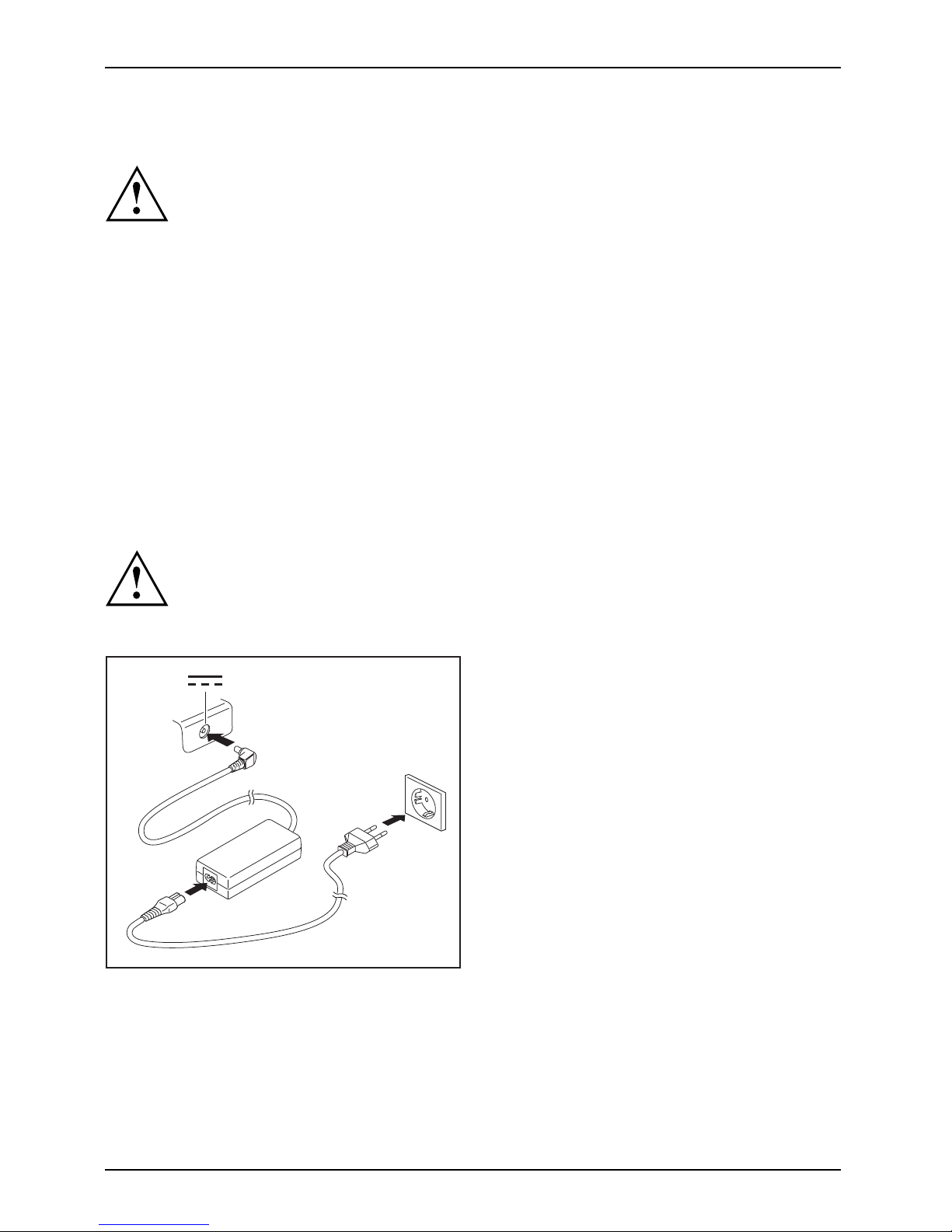
Observe the safety notes in the enclosed "Safety/Regulations" manual.
The supplied power cable conforms to the requirements of the country in
which you purchased your device. Make sure that the power cable is approved
for use in the country in which you intend to use it.
3
1
2
► Connect the power cable (1) to the
mains adapter.
► Plug the mains cable (2) into a mains outlet.
► Connect the mains ad apter cable (3) to
the DC jack (DC IN) of the device.
16 Fujitsu Technology Solutions
Page 21
First-time setup of your device
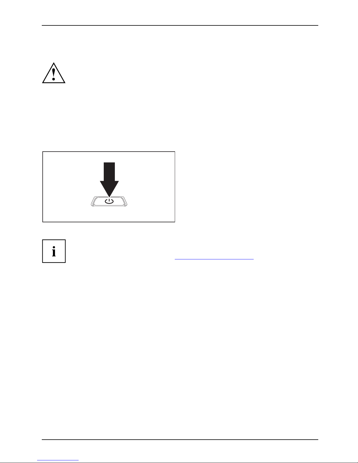
Switching on the device for the first time
Switchingonforthefirsttime
On devices with ON/OF F switch for wireless components: Slide the ON/OFF switch
for wireless components to the ON position before switching on the device.
When you switch on the device for the first time, the s upplied software is
installed and configured. Because this procedure must not be interrupted,
you should set aside enough time for it to be fully completed and connect
the device to the mains using the mains adapter.
During the installation process, DO NOT restart the device unless
you are requested to do so!
To make it easier to use y
our device for the first time, the operating system
is pre-installed on th
e hard disk.
► Switch on your device.
► During installation, follow the instructions on screen.
If a Windows operating system is installed on your device, you will find more
information on the system and drivers, help programmes, updates, manuals etc.
on the device or on the Internet at "
http://ts.fujitsu.com/support".
Fujitsu Technology Solutions 17
Page 22
Working with the notebook
Working with the notebook
Notebook,operationNotebook
This chapter describes the basics for opera ting your notebook. Please read the chapter
entitled "
Connecting ext ernal devices", Pag e 62 for instructions on how to connect
devices such as a mouse and a printer to the notebook.
Please refer to the notes in "Important notes", Page 12.
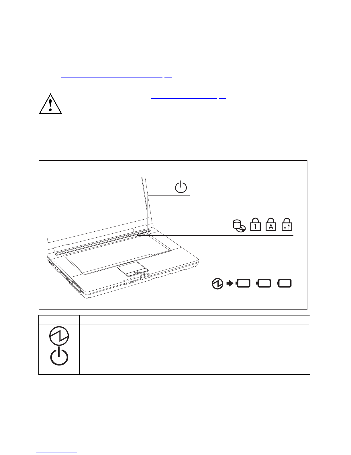
Status indicators
Statusindicatorpanel
The status indicators provide information about the status of the power supply,
the drives and the keyboard functions.
E
1
2
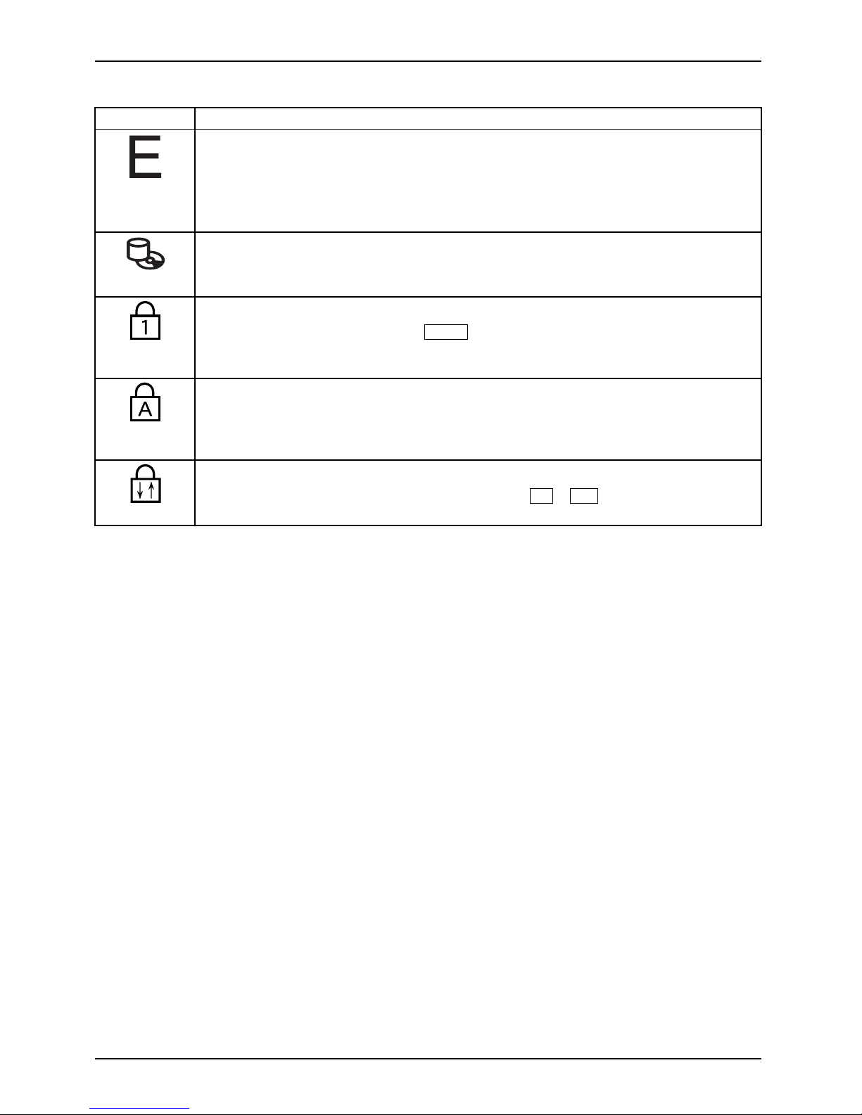
Indicato
r
Descript
ion
Power-o
n indicato r
Power-onindicatorIndicat or
•Theind
icator is illuminated: The notebook is switched on.
•Theindicatorflashes (1 second on/1 second off): The notebook is in power
saving mode.
•Thein
dicator is not illuminated: The notebook is switched off or is in
Save-
to-Disk mode.
18 Fujitsu Technology Solutions
Page 23
Working with the notebook
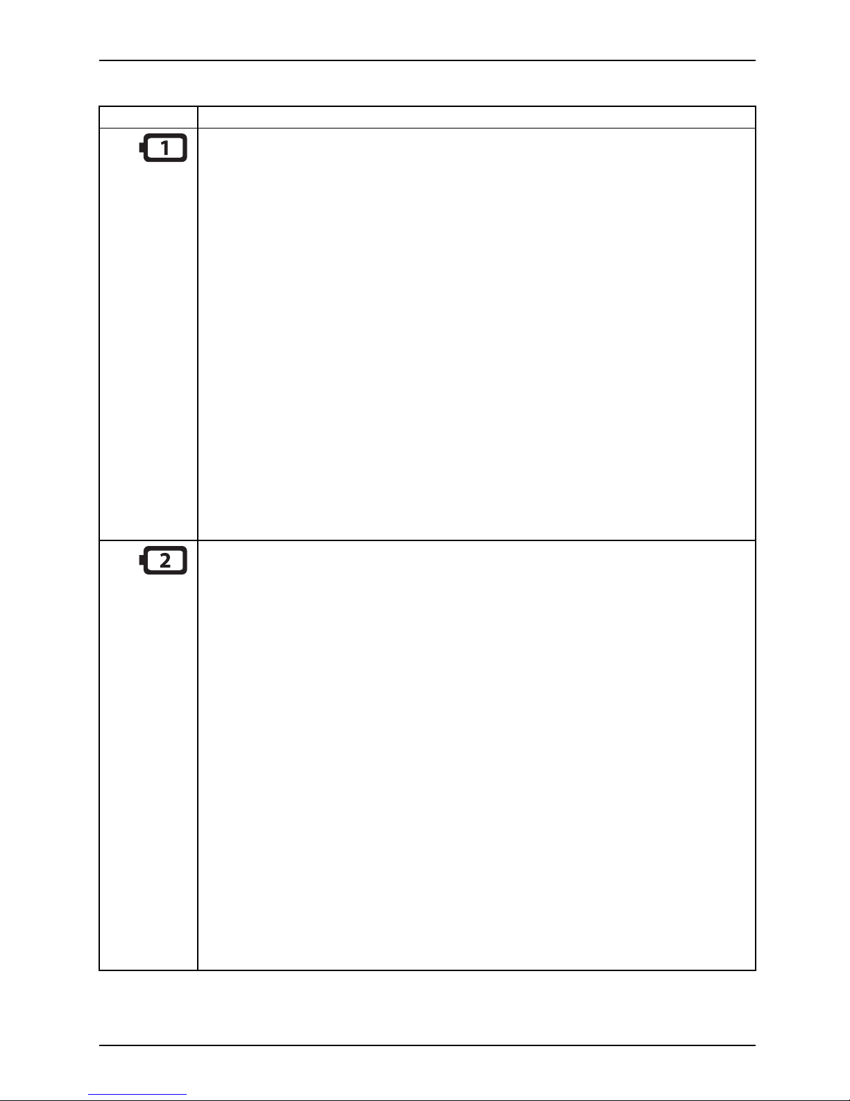
Indicator Description
First battery indicator
• The indicator lights up green: The first battery is charged to between 51% and
100% of maximum capacity.
• The indicator slowly flashes green (1 seco nd on/5 seconds off): The notebook
is in suspe nd mode a nd powe r is being supplied by the first battery. The first
battery is charged to between 51% and 100% of maximum capacity.
• The indicator lights up orange: The mains adap ter is con nect ed and the first
battery is being cha rged. The first battery is charged to between 13% and
50% of maximum capacity.
• The indicator slowly flashes orange (1 second on/5 seconds off): The notebook
is in suspe nd mode a nd powe r is being supplied by the first battery. The first
battery is charged to between 13% and 50% of maximum capacity.
• The indicator flashes orange (for four seconds after installing the battery): The
battery charge level is being checked.
• The indicator lights up red: The mains adapter is connected and the first
battery is being charged. The first battery is charged to between 0% and 12%
of maximum capacity.
• The indicator slowly flashes red (1 second on/5 seconds off): T he notebook
is in suspe nd mode a nd powe r is being supplied by the first battery. The first
battery is charged to between 0% and 12% of maximum capacity.
• The indicator flashes red (1 second on/1 second off). Malfunction.
• The indicator is n ot illuminated: The first battery is not installed or is not charged.
Second battery indicator
• The indicator lights up green: The second battery is charged to between 51%
and 100% of its capacity.
• The indicator slowly flashes green (1 seco nd on/5 seconds off): The notebook
is in suspend mode and power is being supplied by the second battery. The
second battery is charged to between 51% and 100% of its capacity.
• The indicator lights up orange: The mains adapter is connected and the second
battery is being charged. The second battery is charged to between 13% and
50% of its capacity.
• The indicator slowly flashes orange (1 second on/5 seconds off): The notebook
is in suspend mode and power is being supplied by the second battery. The
second battery is charged to between 13% and 50% of its capacity.
• The indicator flashes orange (for four seconds after installing the battery): The
battery charge level is being checked.
• The indicator lights up red: The mains adapter is connected and the second
battery is being charged. The second battery is charged to between 0% and
12% of its capacity.
• The indicator slowly flashes red (1 second on/5 seconds off): T he notebook
is in suspend mode and power is being supplied by the second battery. The
second battery is charged to between 0% and 12% of its capacity.
• The indicator flashes red (1 second on/1 second off). Malfunction.
• The indicator is not illuminated: The second battery is not installed or is not
charged.
Fujitsu Technology Solutions 19
Page 24
Working with the notebook
Indicator Description
Energy saving functions indicator
• The indicator is illuminated: The energy saving functions are enabled (e.g.
reduce screen brightness).
• The indicator is not illuminated: The energy saving functions have been
disabled.
Drive indicator
IndicatorCD/D VDindicator
The indica tor is illuminated: The hard disk drive or the CD/DVD in the optical drive
of the notebook is being accessed.
Num Lock indicator
IndicatorNum Lock
The indicator is illuminated: The
Num
key has been pressed. The virtual
numerical keypad is activated. You can output the characters indicated on the
upper right of the keys.
Caps Lock indicator
IndicatorCap s Lock
The indicator is illuminated: The Caps Lock key has been pressed. All the
characters you type will appear in upper case. In the case of overlay keys, the
character printed on th e upper left of the key will appear when that key is pressed.
Scroll Lock indicator
IndicatorScrollLockIndicatorScrollLock
The indicator is illuminated: The key combination
Fn+Scr
has been pressed. The
effect that this key has varies between applications.
20 Fujitsu Technology Solutions
Page 25
Working with the notebook
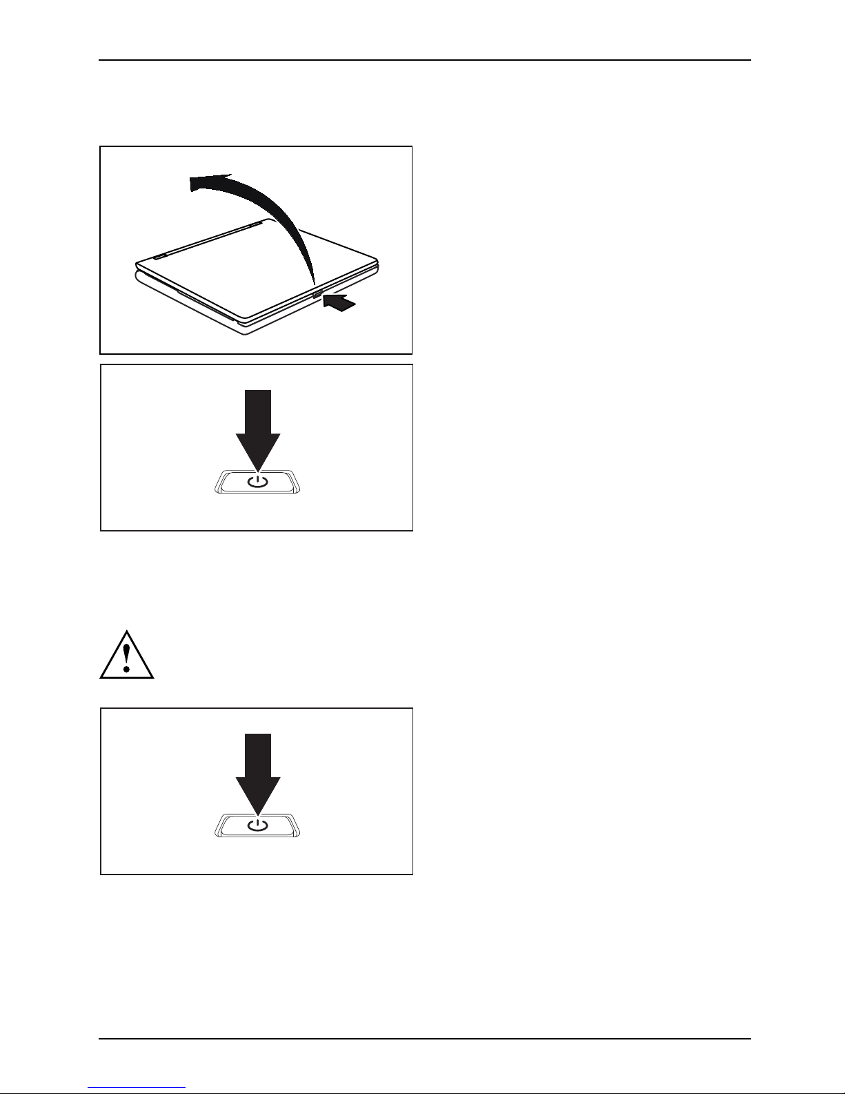
Switching on the notebook
1
2
► Press on the unlocking lever (1).
Notebook
The monitor is unlocked.
► Lift up the LCD monitor (2).
► Press the ON/OFF swit
ch for about one
second to switch the
notebook on.
The power-on indicator of the notebook lights up.
Notebook: switching off
Back up your data and close all applications before you switch off your
device. Otherwise data might be lost.
► Shut down the operating system properly
(e. g. from the Windows Start menu, by
clicking on Start – Shut Down – OK).
Notebook
► If the notebook is not switched off
automatically, press the ON/OFF switch
for approx. five seconds.
► Close the L CD screen.
Fujitsu Technology Solutions 21
Page 26
Working with the notebook
Keyboard
KeyboardNumeric keypadNumerickeypadButtons
The keyboard of your notebook is subject to continuous wear through normal
use. The key markings are especially prone to wear. The key markings are
liable to wear away over the life of the notebook.
The keyboard has been desig
ned to provide all the functions of an enhanced keyboard.
Some enhanced keyboard fun
ctions are mapped with key combinations.
The following descriptio
n of keys refers to Windows. Additional functions supported by the keys
are described in the relev
ant manuals supplied with your application programs.
The figure below shows how
to access the different characters on keys with overlaid functions.
The example applies when
the Caps Lock key ha s not been activated.
The illustrations show
n below may differ from you r actual device.
0
=
}
+
+
Num
Alt Gr
=
0
}
=
0
}
=
0
}
=
0
}
22 Fujitsu Technology Solutions
Page 27
Working with the notebook
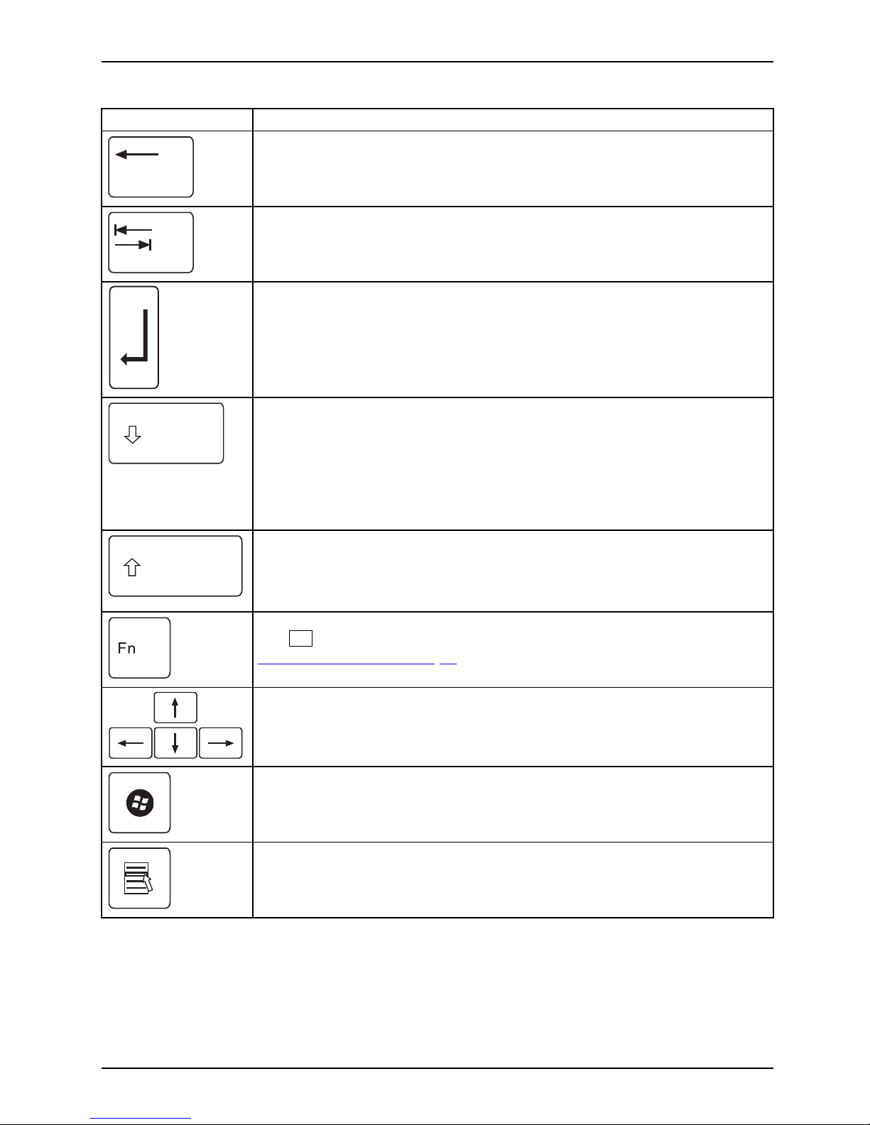
Key Description
Backspace key
The Ba ckspace key deletes the character to the left of the cursor.
BackspaceBackspace
Tab key
The Tab key moves the cursor to
the next tab stop.
Tabkey
Enter key (return)
The Enter key terminates
a command line. The command you have entered
is executed when you pres
sthiskey.
EnterkeyReturnEnterLinefeed
Caps Loc k key
The Caps Lock key activates the Caps Lock mode, and the corresp onding
icon is displayed in the Windows information area. In Caps Lock mode, all
of the characters you type appea r in upper case. In the case of overlay
keys, the character printed on the upper left of the key will appear when
that key is pressed. To cancel the Caps Lock function, simply press the
Caps Lock key again.
ShiftkeyCap sLock
Shift key
The Shift key ca
uses uppercase characters to appear. In the case of overlay
keys, the chara
cter printed on the upper left of the key appears when that
keyispressed.
ShiftkeyShift
Fn button
The
Fn
key enabl
es the special functions indicated on overlay keys (see
"
Key combina
tions", Page 24).
Fnkey
Cursor keys
The cursor
keys move the cursor in the direction of the arrow, i.e. up, down,
left, or ri
ght.
CursorkeysCursorcontrolkeys
Start key
The Start
key opens the Windows St art menu.
Startkey
Menu key
The Menu key invokes the menu for the marked item.
Fujitsu Technology Solutions 23
Page 28
Working with the notebook
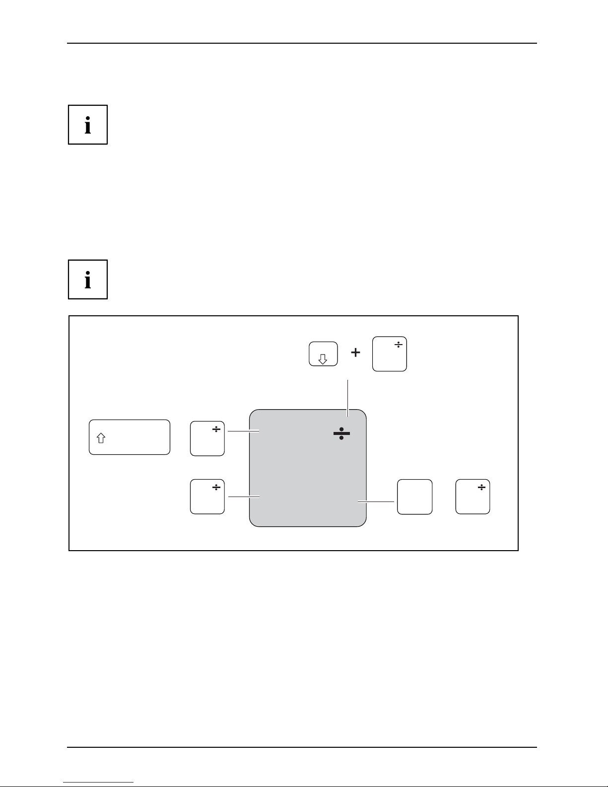
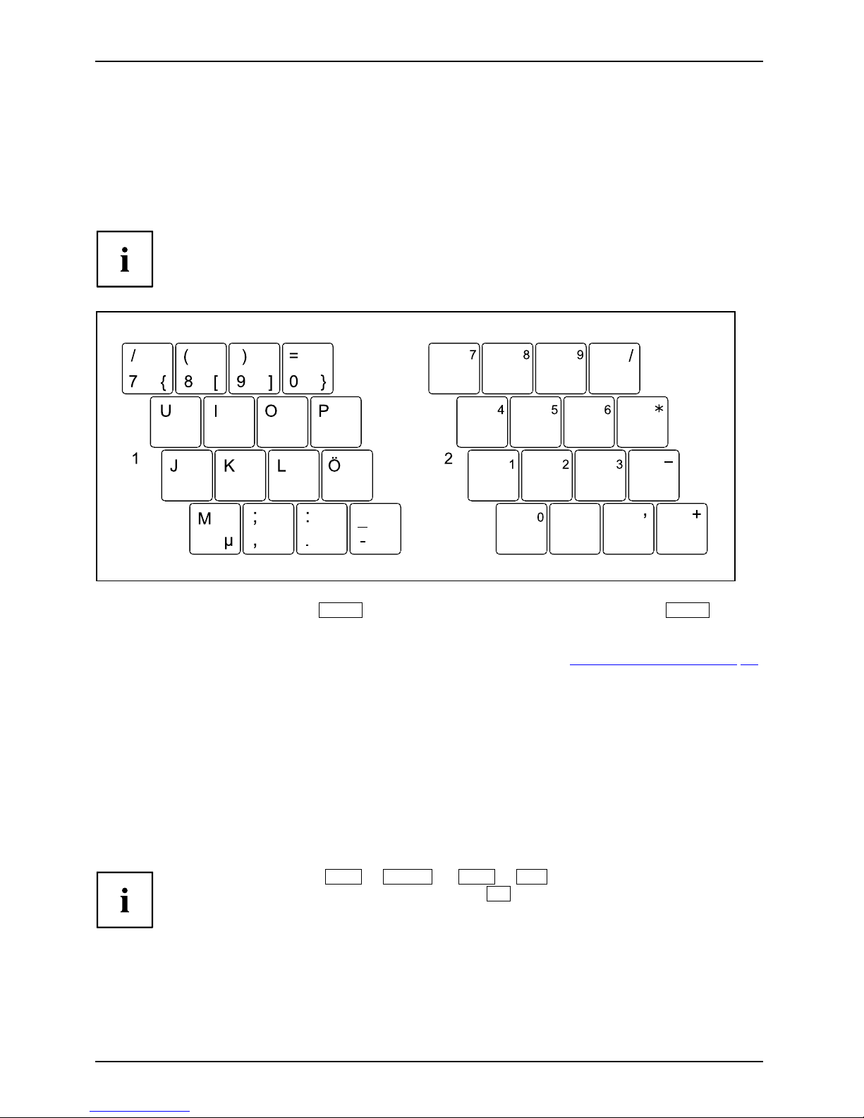
Virtual numeric keypad
NumerickeypadVirtualnumericke ypadNumLock
To provide the convenience of a numeric keypad, your keyboard is equipped with a virtual
numeric keypad. The special k eys of the virtual numeric keypad are recognisable by the numbers
and symbols printed in the upper right corner of each key. If you ha ve switched on the virtual
numeric keypad, you can output the characters shown on the upper right of the keys.
The keyboard layout shown below may differ from your actual device.
1 = Valid characters when the
Num
key is not activated
2 = Valid characters when the
Num
is activated
Furthe
r information about the status indicators can be found in chapter "
Status indicators", Page 18.
Key combinations
The following description of key combinations refers to functions when using
Microsoft Windows. Some of the following key combinations may n ot function in
other operating systems and with some device drivers.
Key combinations are entered as follows:
► Press and hold the first key in the combination.
► While holding the first key down, press the other key or keys in the combination.
The key combination
Ctrl
+
Alt Gr
or
Ctrl
+
Alt
canbeusedon
external keyboards that do not not feature a
Fn
key.
24 Fujitsu Technology Solutions
Page 29
Working with the notebook
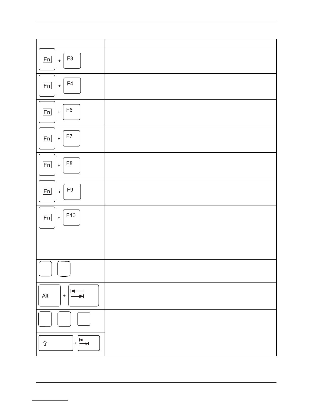
Combination Description
Enable/disable loudspeak ers
Fn+F3LoudspeakersLoudspeakers
This key combination switches y
our notebook’s loudspeakers off
and on.
Switching the t ouchpad on/of
f
Fn+F4TouchpadLoudspeakers
This key combination enables
and disables the touchpad.
Decrease screen brightness
Fn+F6Screenbrightne ss
This key combination decreases the brightness of the screen.
Increase screen brightness
Fn+F7Screenbrightne ss
This key combination increases the brightness of the screen.
Decrease volume
Fn+F8Volum e
This key combination reduces the volume of the integrat ed
loudspeakers.
Volume increase
Fn+F9Volum e
This key combination raises the volume of the integrated
loudspeakers.
Toggle output screen
Fn+F10Toggleoutput
screen
If an external monitor is connected, the monitor on which the output is
to be displayed can be selected with this key combination.
You can opt to use:
• just the notebook’s LCD screen
• just the external monitor
• both the LCD screen and the external monitor
+
Ctrl
C
Halt current operation
Ctrl+C
This key combination can be used to halt an operation instantly
without clearing the keyboard buffer.
Switch be
tween open applications
With this
key combination y ou can switch between several open
applica
tions.
Alt+Tab
AltCtrl
Del
++
Windows Security/Task Manager
This key combination opens the Windows Security/Task Manager
window.
Ctrl+Alt+Del
Back tab
This key combination moves the cursor back to the previous tabular
stop.
Shi
ft+Tab
Bac
ktab
Fujitsu Technology Solutions 25
Page 30
Working with the notebook
Key combinations using the Windows keys are detailed in the manual
for your operating system.
Country and keyboard setting
s
If you want to change the country and keyboard settings, proceed as follows:
► Enter the settings by clicking Start – (Settings) – Control Pane l – Time, Regional and Language Options.
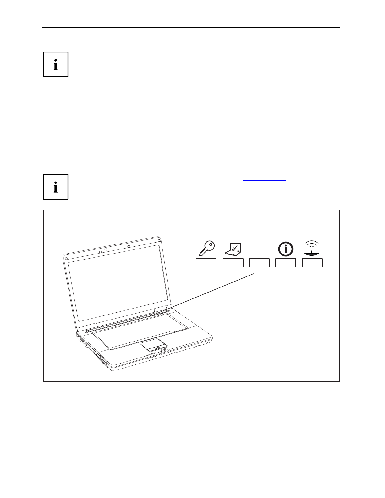
Application keys
Applicationkeys
Your notebook is equipp
ed with five ap plication keys.
All application butt
ons are freely programmable, see "
Programming
the application keys
", Page 27.
E
26 Fujitsu Technology Solutions
Page 31

Working with the notebook
Button Description
Lock Workstation key
This key allows you to lock your workstation.
Mobility C enter key
This button starts the Mobili
ty Center.
E key
The E key is a simple way of activating and deactivat ing power management functions
(e.g. reduce screen brightness), see "
Using the power-management fea tures", Page 39.
I key
With the I key, you can obtain further information about your notebook.
Press this button while in S5 mode to display the rema ining battery power indicator:
• Red: Minimum battery power
• Amber: Medium battery p o wer
• Green: Medium to full battery powe r
Wireless Components key
This application key is used to start the WirelessSelector software. The wireless
components that have been activated in the BIOS Setup can be switched on and off
individually.
Programming the application keys
With the Application Panel you can assign various functions to the application ke ys.
Windows XP
You will find the Application Panel under Start - (Settings) - Control Panel - Additional
Control Panel O ptions - Application Panel.
Windows Vista and Windows 7:
You wi l l find the Application Panel under Start symbol - Programs - Lifebook Application Panel.
Fujitsu Technology Solutions 27
Page 32

Working with the notebook
Touchpad and touchpad buttons
Keep the touchpad clean. Protect it from dirt, liquids and grease.
TouchpadTouchpad
Do not use the touchpad if your fingers are dirty.
Do not rest heavy objects on the touchpad or the touchpad buttons.
1 = TouchStick (can be ordered as an option)
2 = Touchpad
3 = TouchStick buttons
4 = Touchpad buttons
5 = Fingerprint sensor (can be ordered as an
option)
The touchpad enable
s you to move the po inter on the screen.
The touchpad butto
ns allow you to select and execute commands. They correspon d
to the buttons on a c
onventional mouse.
You can also disa
ble th e touchpad via a key combination, to prevent you from moving
the p ointe r on th
e screen unintentionally (see chapter "
Key combinations", Page 24).
Moving the poin
ter
► Move your finger on the touchpad.
Touchpad
or
► Press down g e
ntly with your finger on the TouchStick. If you want to move the pointer
to the left f
or example, press down gently on the left side of the TouchStick.
The pointer will move.
Selecting an item
► Move the pointer to the item you wish to select.
Touchp
ad
► Tap the touchpad once or press the left-han d TouchStick/touchpad button once.
The item is selected.
Executing commands
► Move the pointer to the field you wish to select.
Tou
chpad
► Tap the touchpad twice or press the left TouchStick/touchpad button twice.
The command is e xecuted.
28 Fujitsu Technology Solutions
Page 33

Working with the notebook
Dragging items
► Move the pointer to the item you wish to select.
► Select the desired object and hold down the left TouchStick/touchpad button.
► Drag the object to the desired position.
► Lift your finger from the touchpad.
or
► Lift your finger from the TouchStick.
The item will be moved.
LCD screen
LCDscreenNotes
High-quality TF T displays are installed in notebo oks from Fujitsu Technology Solutions Gmb H. For
technical reasons, TFT monitors are manufactured for a specific resolution. An optimal, c lear
picture can only be ensured with the correct resolution intended for the relevant TFT monitor. A
monitor resolution which differs from the specification can result in an unclear picture.
The screen resolution of the LCD monitor of your notebook is optimally set at the factory.
The standard of production techniques today cannot guarantee an absolutely fault-free screen
display. A few isolated constant lit or unlit pixels (picture elements) may be present. The maximum
permitted number of pixels faults is stipulated in the international standard ISO 9241-3 (Class II).
Example:
A m onitor with a resolution of 1280 x 800 has 1280 x 800 = 1024000 pixels. Each pixel consists of
three subpixels (red, green and blue), so there are almost 3 million subpixels in total. According to
ISO 9241-3 (class II), a maximum of 2 light and 2 dark pixels an d an additional 5 light or 10 dark
subpixels or a corresponding mix may be defective (1 light subpixel counts as 2 dark subpixels).
Pixel
A pixel consists of 3 subpixels, normally red, green and
blue. A pixel is the smallest e lemen t that can be generated
by complete functionality of the display.
Subpixel
A subpixel is a separately addressable internal structure
within a pixel that enhances the pixel function.
Cluster A cluster c
ontains two or more defective pixels or
subpixels
in a 5 x 5 pixel block.
Background lighting
TFT monitors are operated with background lighting. The luminosity of the background
lighting can decrease during the period of use of the notebook. However, you can
set the brightness of your monitor individually.
Synchronising the display on the LCD screen and an external monitor
For more information, please refer to the chapte r "
Key combinations", Pa ge 24
under "Display output, switch between".
Fujitsu Technology Solutions 29
Page 34

Working with the notebook
Webcam
Webcam
Depending on the device variant, a WebCam may be integrated in your notebook.
Depending on the software u
sed, you can use your Webcam to take pictures,
record video clips or take p
art in web chats.
• The picture quality depen
ds on the lighting conditions and the software being used.
• You can only operate th e webcam with a particular application ( e.g. an Internet telephony
program or a video conferencing program w hich supports a webcam).
• When using the webcam the
notebook support must not wob ble.
• The webcam automatically adjusts itself to the current light level. For this reason
the LCD screen may flicker while the light level is adjusted.
Further information on using the webcam and on the additional settings
which are possible for your webcam can b e found in the h elp function
of the program which uses the webcam.
If you wish to carry out a function test with your webcam, you can use the
corresponding test software available at "
http://ts.fujitsu.com/support/".
30 Fujitsu Technology Solutions
Page 35

Working with the notebook
Rechargeable battery
RechargeablebatteryBatteryLife,batteryRechargeablebatteryRechargeablebattery
When not plugged into a mains socket, the notebook runs on its built-in battery. You
can increase the life of th e battery by caring for the battery properly. The average
battery life is around 500 charge/discharge cycles.
You can extend the battery life by taking advantage of the available energy saving functions.
Charging, caring for and maintaining the battery
BatteryBattery
The notebook battery can only be charged, when the ambient temperature
is between 5°C and max. 35°C.
You can charge the battery by connecting the notebook to the mains adapter
(see "
Mains adapter connecting", Page 16).
If the battery is running low you will hear a warning alarm. If you do not connect the mains adapter
within five minutes of the warning alarm described above, your notebook will automatically switch off.
monitoring the battery charging level
BatteryBatterystatusmet
er
Windows also has a "Battery status meter" in the taskbar for monitoring the battery capacity. When
you place the mouse pointer on the battery symbol, the system displays the battery status.
Battery storage
BatteryBatterySelf-discharge,batteryChargingcapacity,battery
Keep the battery pack between 0°C and +30°C. The lower the temperature at which
the batteries are stored, the lower the rate of self-discharge.
If you will be storing ba tteries for a longer period (longer than tw o months),
the battery charge level should be approx. 30 %. To prevent exh aust ive
discharge which would permanently damage the battery, check the level
of charge of the battery at regular intervals.
To be able to make use of the optimal charging capacity of the batteries, the battery
should be completely discharged and then fully recharged.
If you do not use the batteries for long periods, remove them from the
notebook. Never store the batteries in the device.
Removing and installing the battery
Only use
rechargeable batteries approved by Fujitsu Technology
Solutio
ns for your notebook.
Never us
e force when fitting or removing a battery.
Make su
re that no foreign bodies get into the battery connections.
Never s
tore a battery for longer periods in the discharged state. This
can ma
ke it impossible to recharge.
Fujitsu Technology Solutions 31
Page 36

Working with the notebook
Removing a battery
► Prepare for removal, see chapter " Preparing to remove components", Page 69.
1
1
2
► Press the two unlocking levers (1).
► Remove the b attery from the battery compartment (2).
32 Fujitsu Technology Solutions
Page 37

Working with the notebook
Installing a battery
1
► Position the battery at the edge.
► Push the battery into the battery slot until you feel it lock into place (1).
► Complete the removal, see chapter "
Finishing component removal", Page 72.
Module
ModulebayModules
The design of your notebook enables the flexible use of notebook batteries and drives. The
following mo dules can be operated in the module bay of your notebook:
• Second battery
• Second hard disk drive
• Optical drive
• Empty plug-in unit (save weight)
Only use modules designed for your notebook.
Do not u se force when installing or removing the module.
Make sure that no foreign objects enter the module bay.
You can swap modules during operation. This means you do not
need to switch off the notebook.
To replace a module, simply click on the corresponding icon in the
task bar and then on Exit or Select - Exit.
The module can now be removed without any further actions being necessary.
Fujitsu Technology Solutions 33
Page 38

Working with the notebook
Removing a module
1
2
ModuleDriveWeightSaver
► Pull the unlocking lever in the direction of the arrow (1).
► Now pull the module out of the module bay (2).
34 Fujitsu Technology Solutions
Page 39

Working with the notebook
Installing a module
► Place the module into the module bay so that the contacts enter first.
► Push the module into the module bay until you feel it locking into place.
Optical driv
e
Opticaldrive
This product contains a light emitting diode, classified in accordance with IEC
8251:1993: LASER CLASS 1, and mu st therefore not be opened.
Handling data carriers
Handling
Observe the following guidelines when handling data carriers:
• Avoid touching the surface of a data carrier. Only handle data carriers by th eir edges.
• Always store data carriers in their cases. This will protect the data carrier against
being covered in dust, scratched or damaged in any other way.
• Protect your data carriers against dust, mechanical vibrations and direct sunlight.
• Avoid storing a data carrier in areas subject to high temperatures or hu m idity.
You may use both 8-cm and 12-cm data carriers in the optical drive.
When using a data carrier of lesser quality, vibrations and reading errors may occur.
Fujitsu Technology Solutions 35
Page 40

Working with the notebook
CD/DVD indicator
CD/DVDindicator
The CD/DVD indicator flashes when a data carrier is inserted. The indicator goes out when
the drive is ready for reading. The indicator lights up when the drive is being accessed.
You may only rem ove the data carrier when the indicator is unlit.
If the CD/DVD indicator does not go out after a data carrier has been inserted, but
instead continues to flash, this means that the drive cannot access the data carrier.
Either the data carrier is damaged or dirty or you are using a data
carrier that the drive cannot read.
Inserting or removing a data carrier
InsertingRemoving
The notebook must be switched on.
2
1
► Push the insert/eject button (1).
The drive tray will open.
► Gently pull the drive tray (2) completely out.
► Place the data carrier in the drive tray with
the printed side facing upwards.
or
► Remove a data carrier that has
been inserted.
► Push in the drive tray until you
feel it lock into place.
36 Fujitsu Technology Solutions
Page 41

Working with the notebook
Manual removal (emergency removal)
CD/DVD:ManualremovalofdatacarrierEmergencyremovalofdata carrier
In the event of a power failure or damage to th e drive, you can remove the data carrier manually.
1
2
► Switch your notebook off.
► Push a pen or a piece of wire (such as a
paperclip) firmly into the opening (1).
The drive tray is ejected. You can now pull
the drive tray (2) out of the drive.
Removing and fitting the dust removal cover
(ventilation slot cover)
The description below applies to both vent covers.
In order to ensure optimum cooling of the components in your notebook, you
should periodically clean the ventilation slot of the heatsink.
This ensures optimum fan performance. You can achieve the best cleaning
results with a small hand-held vacuum cleaner.
If necessary, you can also use a dry brush to release dust from the ventilation slots.
Do not use any cleaning liquids! Ensure that no liquid enters the device.
To avoid overheating of the device, do not remove the ventilation slot
cover when the device is switched on.
► Prepare fo
r removal, see chapter "
Preparing to remove components", Page 69.
Fujitsu Technology Solutions 37
Page 42

Working with the notebook
1
2
► Press and hold the lock of the ventilation
slot cover (1) and remove it from its slot (2).
► Clean the dust chamber.
1
► Insert the ventilation slot cover into the
slot (1) at an angle as shown, and ensure
that you feel it click into place.
► Complete the removal, see chapter
"
Finishing compo nent removal", Page 72.
38 Fujitsu Technology Solutions
Page 43

Working with the notebook
Using the power-management features
PowerPowerBattery
The notebook uses less power when the available power-m anagemen t features are used. You
will then be able to work longer when using the battery before having to recharge it.
Power efficiency is increased and environm ental pollution reduced. By
choosing the best power options, you can make sign ificant savings and
at the same time help protect the environment.
When you close the LCD screen, depending on the setting in Windows, the
notebook automatically enters a power saving mode.
We recommend the following settings:
Function On external power On battery power
Turn off monitor After 10 minutes After 5 minutes
Turn off hard disk(s) After 15 minutes After 10 minutes
Energy saving (S3) After 20 minutes After 15 minutes
Hibernate mode (S
4)
After 1 hour After 30 minutes
► Select the power ma
nagement functions in your Control Panel.
► Select the Screen Saver in your Control Panel.
or
► Right-click on the desktop. Switch on the screen saver by clicking Personalization –
Change screen saver.
If you need further information about an option, you can get help with most
settings by pressing
F1
to open the Microsoft Help.
When the notebook is in powe r-saving mode, the following must be remembered:
During power saving mode, open files are held in the main memory
orinaswapfile on the hard disk.
Never turn off your notebook while it is in a power saving mode. If the built-in battery is
nearly empty, close the open files and do not go into power saving mode.
If you do not intend to use your notebook for a long period of time:
► Exit power saving mode if necessary via the mouse or keyboard or by switching on the
notebook.
► Close all opened programs and completely shut down the notebook.
Fujitsu Technology Solutions 39
Page 44

Working with the notebook
Memory cards
Slot
Your notebook is equipped with an integrated memory card reader.
Observe the manufacturer’s instructions when handling the memory cards.
Memorycard
Supported formats
Your notebook supports the following formats:
• Secure Digital (SD
TM
card)
•MemoryStick(MS)
• Memory Stick Pro
Inserting the memory card
► Carefully slide the memory c ard into the
slot. The label should be facing upward. Do
not apply excessive force, as otherwise the
delicate contact surfaces could be damaged.
Memorycard
Depending on the particular type
used, the memory card may protrude
slightly from the slot.
40 Fujitsu Technology Solutions
Page 45

Working with the notebook
Removing the memory card
Memorycard
In order to protect your data, always follow the correct procedure
for removing the card outlined below.
You can stop the memory card via the corresponding icon in the task bar:
► Left-click on the icon.
► Select the card you want to stop and remove.
► Press the Enter key.
Wait for the dialogue box which tells you that it is now safe to remove the memory card.
1
2
► On devices with card locking: Press
on the storage card (1).
Memorycard
The storage card is released and
can now be removed.
► Pull the storage card out of the slot (2).
PC cards and ExpressCards
PCcardExpressCardCardBus, seePCcardPCM C IA, se e PCcardPC-card,seeP Ccard
An ExpressCard slot enables operation of an ExpressCard/34 or ExpressCard/54.
A PC card slot enables the notebook to operate one type I or type II PC card.
Please read the documentation on the PC card and/or on the ExpressCard
and follow the manufacturer’s instructions.
NeveruseforcewheninstallingorremovingaPCcardoranExpressCard.
Fujitsu Technology Solutions 41
Page 46

Working with the notebook
Inserting the card
Keep the placeholder for the slot in a safe place. When you remove t he card again you
must reinstall the placeholder. This prevents foreign bodies from getting into the slot.
1
2
► If the eject button (1) is recessed, press it
once so that it d isengages. Now p ress the
eject button again so that the placeholder
protrudes slightly from the notebook.
► Pull the card placeholder out of the slot (2).
► Insert the card into the slot guide with
the connection contacts first.
► Gently push the card into the slot either
until it will go no further or you feel it
engage. Do not use excessive force.
Depending on the type, the card may
protrude slightly from the slot.
Please see the documentation relating to the card for driver installation instructions.
42 Fujitsu Technology Solutions
Page 47

Working with the notebook
Removing the card
Always remove the card according to the rules described below, to
ensure that none of your data is lost.
You can stop the card using the corresponding icon in the task bar:
► Left click on the icon to safely remove hardware, located in the taskbar.
► Select the card you want to stop and remove.
► Press the "Enter" key.
Wait for the dialog b ox which tells you that it is now safe to remove the card.
1
2
► If the eject button is lowered, you must
first cause the eject button to release
from the note book casing. To do this,
press the eject button until it pops out.
Press the eject button (1) so that the card
protrudes a little from the notebook.
► Pull the card out of the slot (2).
► Insert the card placeholder into the
slot guide.
► Carefully slid
e the placeholder for the
card as far as it
willgointotheslot.
Do not use exce
ssive force.
Loudspeakers and microphones
MicrophoneLoudspeaker sBass lo udspeaker(subwoofer)Volume control
Information on the exact position of the speakers and microphone can be found
in "
Ports and operating elements", Page 9.
Please refer to chapter "
Key combinations", Page 2 4 for information on setting the volume
and also enabling/disabling the loudspeakers using key combinations.
If you attach an external microphone, the built-in microphone is disabled.
When you connect headphones or external speakers, the built-in speakers are disabled.
Information on connecting headphones and a microphone can be found
in "
Connecting external devices", Page 62.
Fujitsu Technology Solutions 43
Page 48

Working with the notebook
Integrated 56k modem
56kmodemModem
Whether or not your device has a 56k modem depends on the device
configuration you have ordered.
The integrated 56k modem supports all data communication applications, such as:
• Modem operation: High-speed downloads at up to 56,000 bit/s (V.9x).
Downward-compatible to V.34 modems.
• Fax operation: Transmitting and receiving at up to 14,400 bit/s
• Simple software-based country adaptations
The modem complies with the EU Directive 91/263/EEC (Telecommunications terminal equipment
directive) and has been checked in agreement with the guideline TBR-2 1.
The modem can be operated in the following countries:
Multifrequency (MFC) dialling: Belgium, Denmark, Germany, Finland, France,
Greece, Great Britain, Holland, Ireland, Iceland, Italy, Luxembourg, Norw ay,
Austria, Portugal, Sweden, Switzerland and Spain.
Pulse dialling: Belgium, France, Holland and Italy.
Also in: Poland, Slovenia, South Africa and Hungary.
44 Fujitsu Technology Solutions
Page 49

Working with the notebook
Connecting notebook modem to telephone wall socket
If you use a modem, incompatibilities with the local telephone system may result.
This may result in poor performance, or the modem may not work at all.
Check whether you need a country-specific telephone adapter (available
as an optional accessory).
The modem cable and the country-specific telephone adapter are not included
in delivery. You can order these as an option.
Please note that the telephone line is busy and that you cannot use your
telephone if th e modem cable is plug ged into the telephone wall socket. Pull the
modem cable out of the telephone socket after you have finished your internet
session or the fax mode and reconnect the telephone cable.
4
3
1
2
► Connect the modem cable to the modem
port of the notebook (1).
Modem
► Plug the modem cable (
2) into the
country-specificte
lephone adapter (3).
► Connect the modem cable to your
telephone wall socket (4).
Fujitsu Technology Solutions 45
Page 50

Working with the notebook
SIM card
A SIM Card (Subscriber Identity Module) is a chip card which is inserted in a m obile telephone or
notebook to enable access to a mobile radio network in conjunction with an installed UMTS module.
Follow the instructions supplied by the provider of the SIM card.
The SIM card slot is located in the battery compartment and can only
be accessed when the battery is removed.
Inserting the SIM card
► Prepare for insertion of the SIM card, see chapter "Preparing to remove components", Page 69.
1
2
a
► Slide the SIM card into the slot (1)
until it is felt to engage, as shown in
the battery compartment.
► Slide the SIM card lock (a) in the
direction of the arrow (2).
► Complete the in
stallation, see chapter "
Finishing component removal", Page 72.
Removing a SIM card
► Prepare for removal of the SI M card, see chapter " Preparing to remove components", Page 6 9.
a
1
2
► Slide the SIM card lock (a) in the
direction of the arrow (1).
► Press on the edge of the SIM card so that
it jumps up slightly out of the slot.
► Pull the SIM card out of the slot in the
direction of the arrow (2).
► Comple
te the removal, see chapter "
Finishing component removal", Page 72.
46 Fujitsu Technology Solutions
Page 51

Working with the notebook
Wireless LAN/ Bluetooth (device-dependent)
/ UMTS (device-dependent)
The installation of a radio components not approved by Fujitsu Technology
Solutions will invalidate the certifications issued for this device.
Switching the wireless compon ents on and off
Before switching on your device for the first time, the on/off switch for
radio components must be in the "ON" position.
► Slide the ON/OFF switch into the "ON"
position to activate the radio components.
WirelessLANWirelessLANBl uetoothB l uetooth
or
► Slide the ON/OFF sw
itch to the
"OFF" position to
deactivate the
radio components
.
If you switch off the radio components, the wireless LAN transmission unit (antenna)
and, if present, the Bluetooth and U M TS module will also be switched off.
You can enable and disable the installed radio components individually
using the WirelessSelector programme
You can also deactivate the wireless com ponents individually in the BIOS Setup.
For this to occur, you must either not have assigned a supervisor password or if a
supervisor password has been assigned, you must know this password.
Pay attention to the additional safety notes for devices with radio components
provided in the "Safety/Regulations" manual.
Details on using Wireless LAN can be found in the online help system
included in the Wireless LAN software.
You can find more information on how to use Bluetooth on the C D you
received with your Bluetooth software.
You can obtain more information on UMTS from your service provider.
Fujitsu Technology Solutions 47
Page 52

Working with the notebook
Setting up WLAN access
• Requirement: A WLAN must be available and you must have the
corresponding access information.
Information on configuring the WLAN access can be found in the
documentation for your operating system.
Access via UMTS
If you have ordered an integrated UMTS module with your system, you can enjoy the
best reception and maximum energy efficiency, without any disruptive ca bles or aerials.
The optional UMTS module is ready for use immediately.
If you have not ordered a UMTS module, you can purchase the accessories for UMTS reception
from specialised dealers or from your Fujitsu Techn ology Solutions dealer.
You will find information on establishing the connection with the UMTS network
in the documentation for t he hardware used.
Your device can connect with the Internet via UMTS. To do this, use one of
the following types of connection:
• an integrated UMT S module (depending on your model variant)
• a USB dongle (a USB stick with your mobile phone provider’s SIM card)
• a UMTS ExpressCard (to be inserted in the ExpressCard slot of your device)
• a mobile end-device (e.g. mobile phone with Bluetooth or cable connection)
Ethernet and LAN
EthernetLAN
The internal network module of your notebook supports Ethernet LAN. You can use it to
establish a connection to a local network (LAN = Local Area Network).
2
1
► Connect the network cable to the LAN
port of the notebook (1).
► Connect the ne twork cable to your
network connection (2).
Your n
etwork administrator can help you to configure and use the LAN connections.
The n
etwork cable is not included in the delivery scope. This type of
cabl
e can be obtained from a specialist dealer.
48 Fujitsu Technology Solutions
Page 53

Working with the notebook
Your Port Replicator (optional)
Your Port Replicator is a device that enables you to quickly connect your notebook
to your peripherals, such as a monitor, printer etc.
The features offered by the Port Replicator include standard ports for
monitor, audio, mouse and keyboard.
You need only dock the notebook in order to use your peripheral device s.
Ports on the Port Replic
ator
1
17
16
15
2
3
4
5
6
7
8
9
10
11
12
13
14
1 = Kensington Lock
2 = LAN port
3=USBports
4 = Parallel port
5 = Serial port
6 = VGA monitor port
7 = DVI monitor port
8 = DisplayPort
9 = e-SATA port
10 = USB ports
11 = DC input connector (DC IN)
12 = Kensington Lock
13 = Headphones port
14 = Microphone port/Line In
15 = Connector on the Port Replicator for
the docking port on the underside
of the notebook
16 = ON/OFF switch
17 = Unlocking lever
Fujitsu Technology Solutions 49
Page 54

Working with the notebook
Connecting the notebook to the Port Replicator
If you connect the notebook to the Port Replicat or during operation, problems can
occur. We recommend that you switch off the notebook beforehand.
The mains adapter must be connected to the Port Replicato r when the
notebook is connected to the Port Replicator.
We recommend that the notebook is not operated with the LCD monitor closed when
the notebook is connected to the Port Replicator. The resulting overheating can
cause reduced performance and increased activity of the integrated fan.
PortReplicator
► Switch the notebook off.
► Remove the power plug of the mains adapter from the mains socket.
► Disconnect the mains adapter cable from the DC socket (DC IN) of the notebook.
a
1
► Ensure that the positioning aid (a) of the Port Replicator is folded in (1).
50 Fujitsu Technology Solutions
Page 55

Working with the notebook
1
► Position the notebook so that it is in line with the back edge of the Port
Replicator and the positioning aid.
► Push the notebook onto the Port Replicator in the direction of the arrow
(1) until you notice it engage.
Fujitsu Technology Solutions 51
Page 56

Working with the notebook
Connecting the mains adapter to the Port Replicator
1
2
3
► Connect the mains adapter cable to the DC
jack (DC IN) of the Port Replicator (1).
► Connect the power cable to the
mains adapter (2).
► Plug the power cable into the mains
socket (3).
When the notebook is conne cted to a Port Replicator, the operating system creates
a hardware profile for the "Docked" mode. In this profile, for example, the setting is
saved as to which monitor was last used for output. This pro file will b e loaded, as
soon as the notebook is connected to a Port Replicator of the same type.
Switching on the notebook via the port replicator
► Press the ON/O
FF switch on the port
replicator to
switch the notebook on.
The power-on i ndicator of the Port
Replicator lights up.
Switchi
ng off notebook via Port Replicator
► Close all applications and shut down your operating system (please refer
to the manual for the operating system).
If the notebook cannot be shut down properly, press the ON/OFF button
on the Port Replicator for approx. four seconds. The notebook will switch
off. Any unsaved data may however be lost.
52 Fujitsu Technology Solutions
Page 57

Working with the notebook
Disconnecting the notebook from the Port Replicator
Problems may occur if the notebook is removed from the Port Replicator during
operation. We recommend that the notebook is switched off or that the appropriate
undocking function provided by the operating system is executed.
► Switch the notebook off.
2
1
► Pull the u n
locking lever in the direction of the arrow (1), until you hear the notebook unlatch.
► Lift off the notebook (2).
Fujitsu Technology Solutions 53
Page 58

Security functions
Security functions
Securityfunctions
Your notebook has several security features that you can use to secure your
system from unau thorised access.
This chapter explains how to use each function, and what the benefits are.
Please rem ember that in some cases, for example, forgetting your password,
you may be locked out and unable to access your data. Therefore,
please note the following information:
• Make regular backups to external data c arriers such as external hard
drives, CDs, DVDs or Blu-ray Discs.
• Some security functio
ns need you to choose passwords. Make a note
of the passwords and ke
ep them in a safe place.
If you forget your passwords y ou will need to contact the our Service
Desk. Deletion or resetting of passwords is not covered by your warranty
and a charge will be made for assistance.
Configuring the fingerprint sensor
FingerprintsensorFingerprintsensor
Whether or not your device has a fin gerprint sensor depends on the
device configuration you have ordere d.
The fing erprint sensor can record an image of a fingerprint. With additional fingerprint
software, this image can be processed and used instead of a password.
1
► You must install the fingerprint software
in order to be able to use the
fingerprint sensor (1).
54 Fujitsu Technology Solutions
Page 59

Security functions
Using the Security Lock
Your device comes w ith a S ecurity Lock mechanism for the Kensington Lock Cable. You
can use the Kensington Lock Cable, a sturdy steel cable, to help protect your notebook
from theft. The Kensington Lock Cable is available as an accessory.
K
► Fit the Kensington Lock Cable to the
mechanism on your notebook.
UsingtheKensingtonLockCableSecurityLockMechanicalbackupAnti-theftprotection
Attach another Kensington Lock Cable to your Port Replicator to protect
your Port Replicator from theft as well.
Configuring passw
ord protection in BIOS Setup Utility
Before using the various options for password protection in the BIOS Setup utility
to increase data security, please observe the following:
Make a note of the passwords and keep them in a safe place. If you forget your
supervisor password you will not be able to access your notebook. Passwords are
not covered by your warranty and a charge will be made for assistance.
Passwordprotection
Your password can be up to eight characters long and contain letters and numbers.
No distinction is made between uppercase and lowercase.
Protectin
g BIOS Setup Utility (supervisor and user password)
If you have opened these operating instructions on the screen, we recommend that
you print out the following instructions. Because you cannot call the instructions
onto the screen while you are setting up the password.
BIOSSe
tupUtility
You prevent unauthorised use of the BIOS Setup Utility with both the supervisor and the user
password. The supervisor password gives you access to all functions of the BIOS Setup
Utility, while the user password only provides some of the functions. You can only set a
user password if a supervisor password has already been assigned.
Please refer to the ""Settings in BIOS Setup Utility", Page 73 section for a
description of how to call up and operate the BIOS Setup Utility.
Fujitsu Technology Solutions 55
Page 60

Security functions
Setting supervisor and user password
► Start the BIOS Setup Utility and go to the Security menu.
► Select the Set Supervisor Password field and press the Enter key.
With Enter new Password: you are asked to enter a password.
► Enter the password and press the Enter key.
Confirm new Password requires you to confirm the password.
► Enter the password again and press the Enter key.
Changes have been saved is a confirmation that the new password has been saved.
► To set the user password, select Set User Password and proceed exactly as
when configuring the supervisor password.
If you do not want to change any other settings, you can exit BIOS Setup Utility.
► In the Exit menu, select the option Save Changes & Exit.
► Select Yes and press the Enter key.
PasswordSupervisorpas swordUserpassword
The notebook w ill be rebooted and the new password will come into effect. It will now be
necessary to first enter your supervisor or user password in order to open the BIOS Setup Utility.
Please note that the user password only provides access to a few of the BIOS settings.
Changing the supervisor or user password
You can only change the supervisor password w hen you have logged into the
BIOS Setup Utility with the supervisor password.
PasswordSupervisorpasswordUserpassword
► Call the BIOS Setup Utility andgototheSecurity menu.
► When changing the password, proceed exactly as for password assignment.
Removing passwords
To remove a passw ord (without setting a new password) perform the following steps:
PasswordSupervisor
password
Userpasswo
rd
► Start the BIOS Setup Utility and go to the Security menu.
► Highlight the Set Supervisor Password or Set User Password field and press the Enter key.
You will be requested to enter the current password by the Enter Current Password prompt.
You will be requested to enter a new password by the Enter New Password prompt.
► Press the Enter key twice.
► In the Exit menu, select the option Save Changes & Exit.
► Select Yes and press the Enter key.
The notebook will now reboot with the password removed.
Removing the supervisor password simultaneously deactivates the user password.
Passw
ord protection for booting of the operating system
With the supervisor password you have set in the BIOS Setup Utility (see
section "
Setting superviso r and user password", P age 56), you ca n also
prevent booting of the operating system.
Operatingsystem
56 Fujitsu Technology Solutions
Page 61

Security functions
Activating system protection
► Start the BIOS Setup Utility and go to the Se curity menu.
Operatingsystem
► Select the PasswordonBootoption an d press the Enter key.
► Select the desired option (Disabled, First Boot or Every B oot) and press t he Enter key
► Select the Save Changes & Exit option under Exit.
The n otebook will reboot. You will be prompted to enter your password ( the supervisor password).
Deactivating system protection
► Start the BIOS Setup Utility and go to the Se curity menu.
Operatingsystem
► Select the PasswordonBootoption an d press the Enter key.
► Select the Disabled option and press the Enter key.
If you do not want to change any other settings, you can exit BIOS Setup U tility.
► Select the Save Changes & Exit option under Exit.
The noteboo k will reboot. The system is no longer password-protected.
Password protection for the hard disk
Passwordprotec
tion:
The had disk password prevents unauthorised access to the hard disk drives
and is checked internally each time the system is booted. T he condition for this
is that you have assigned at least the supervisor password.
Activating hard disk protection
► Call up the BIO
SSetupand select the Security menu.
If you have not assigned BIO S passwords yet, define the supervisor and the user
password now, if desired (see "
Security functions", Page 54).
► Mark the Har
d Disk Security field and press the Enter key.
► In the Drive0 area mark the Set Master Password field and press the Enter key.
Enter new P
assword then appears and you are asked to enter a password.
► Enter the password and press the Enter key.
Confirm ne
w Password requires you to confirm the password.
► Enter the passwo rd again and press the Enter key.
Setup Not
ice: Changes have been saved is displayed to confirm that the
new pass
word has been saved.
► To assign the password for the second hard disk (Drive1), go to the Drive1 area and
select the field Set Master Password, then proceed in exactly the sa m e way as for
setting up the password for the first hard disk (Drive0).
The fie
ld Password Entry on Boot is set to Enabled by default. You can exit the BIOS
Setup
once you have finished changing the settings.
► From the Exit menu, choose the option Exit Saving Changes.
► Pres
s the Enter key and select Yes.
The notebook reboots and your hard disk is now protected with a passw ord. The system
will ask you to enter the password when the notebook is restarted again.
Fujitsu Technology Solutions 57
Page 62

Security functions
Deactivating hard disk protection
To cancel a password without setting a new one, proceed as follows:
► Call up the BIOS Setup and select the Security menu.
► Mark the Hard Disk Security fie ld and press the Enter key.
► In the Drive0 area mark the Set Master Password field and press the Enter key.
You will be initially requested to enter the old password by the Enter current Password prompt.
You will then be requested to enter a new password by the Enter new Password prompt.
► After entering the password, press the Enter key three times.
► From the Exit menu, choose the option Exit Saving Changes.
► Press the Enter key and select Yes.
The notebook reboots, and password protection for the hard disk is cancelled.
► To cancel the password for the second hard disk (Drive 1), go to the Drive1 area
and select the field Set Master Password, then proceed in exactly the same way as
for cancelling the password for the first hard disk (Drive0).
Boot from Removable Media
With this BIOS feature, you can manage/control unauthorised booting of an operating
system from external media (e.g. USB stick, USB CD-ROM drive etc.) We recommend
that you configure the hard disk as the first boot medium in order to prevent access
to your system by boot CDs and bootable media.
The c ondition for this BIOS feature is that you have assigned at
least the supervisor password.
► Call up the BIOS Se tup and select the Security menu.
► Highlight the Boot from Removable Media field and press the Enter key.
► Select the entry All (if you want everyone to be allowed to boot) or Supervisor Only (if you
only want the supervisor to be authorised to do this) and press the Enter key.
If you do not want to change any other settings you can exit the BIOS Setup.
► From the Exit menu, choose the option Exit Saving Changes.
► Press the Enter key and select Yes.
The notebook will restart and the settings will be adopted.
58 Fujitsu Technology Solutions
Page 63

Security functions
Owner Information (device-dependent)
The BIOS feature Owner Information enables you to enter up to 80 characters of text
which is displayed in the bottom left corner of the screen before the operating system
boots up. You could use this featu re for example to put your name and telephone
number on the notebook in case it is lost or stolen.
Requirements:
• You have been assigned at least the supervisor password.
•IntheBOOT menu, the Bo ot time diagnostic screen option is set to enabled.
► Call up the BIOS Setup a
nd select the Security menu.
► Highlight the Owner Information field and press the Enter k ey.
► Add the text you would
like to enter under Set Owner Information.
Setup Notice: Changes have been saved is displayed to confirm that the text has been saved.
► From the Exit menu,
choose the option Exit Saving Changes.
► Press the Enter key and select Yes.
The notebook will
restart an d the Owner Information will be adopted.
Virus Warning (device-dependent)
This field checks the b oot sectors of the hard disk drive to see if any changes have been
made sin ce the previous system start-up. If the boot sector has been changed since the
previous system start-up (e.g. new operating system or virus attack), a warning is displayed
on the screen. The warning will stay on the screen until you acknowledge the changes by
clicking on Confirm or until you set the Virus Warning fu nction to Disabled.
If the boot sectors have been changed and the reason for this is unknown, a
programme for finding computer viruses should be loaded.
Such a change is not only caused by viruses, but also by the boot manager.
This function does not replace proper anti-virus software.
No supervisor password is required to set it up.
► Call up the BIOS Setup and select the Security menu.
► Highlig
ht the Virus Warning field and press the Enter key.
► Select Enabled to activate the Virus Warning function.
► From t
he Exit menu, choose the option Exit Saving Changes.
► Press the Enter key and select Yes.
The no
tebook will restart and the settings will be adopted.
Fujitsu Technology Solutions 59
Page 64

Security functions
SmartCard reader
Securityfunctions,Securityfunctions
Depending on the device configuration level, your notebook is equipped
with a SmartCard reader.
SmartCards are not supplied as s tand ard equipment. You can use all SmartCards that comply with
the ISO standard 7816-1, -2 or -3. These SmartCards are available from various manufacturers.
With the appropriate software you can use your SmartCard as an alternative to password protection,
but also as a digital signature, for encrypting your e-mails or for home banking.
We recommend that you always use two SmartCards. Always keep one of the SmartCards
in a safe place if you are carrying the other SmartCard with you.
In order to be able to take advantage of all the security features of your notebook, you
will need a CardOS SmartCard from Fujitsu Technology Solutions.
The SmartCard can only be used with a PIN, offering maximum protection even if
you lose the SmartCard. In order to m axim ise your security, the CardOS SmartC ard
is disabled if three incorrect attempts are made to enter the PIN.
When you use the CardOS SmartCard for the first time, you will either need to enter the
preset PIN "12345678" or the PIN given to you by y our systems administrator.
Inserting the S
martCard
Do not use force when inserting and removing the SmartCard.
Make sure that foreign objects do n ot fall into the SmartCard reader.
► Slide the SmartCard into the SmartCard
reader with the chip facing upwards (on
some variants it faces down) and to the front.
60 Fujitsu Technology Solutions
Page 65

Security functions
Trusted Platform Module (TPM) (device-dependent)
TPMTrustedPlatformModule
To use the TPM, you must activate the TPM in the BIOS Setup before the software
is installed. The condition for this is that you have assigned at least the supervisor
password (see "
Security functions", Pa ge 54).
Enabling TPM
• Requirement: You have assigned a supervisor password, see "Security functions", Page 54.
► Call up the BIOS Setup an
d select the Security menu.
► Mark the TPM Security Chip Setting field and press the Enter key.
► Select Enabled to acti
vate the TPM.
Once you have activated the TPM the Clear Security Chip option appears.
Select Clear Securit
yChipto delete the holder in the TPM. By clicking on Enabled,
all secret keys (e.g
. SRK - Storage Root Keys, AIK - Attestation Identity Keys
etc.) generated by
applications are deleted.
Please note that yo
u will then no longer be able to access the data you have
encrypted with th
e keys based on that holder.
► Select the Exit Sa
ving Changes option in the Exit menu.
► Press the Enter key and select Yes.
The notebook wil
l restart, and TPM will be enabled after the reboot.
Disabling TPM
• Requirement: You have assigned a supervisor password, see "Security functions", Page 54.
► Call up the BIOS Setup and select the Security menu.
► Mark the TPM Security Chip Setting field and press the Enter key.
► Select Disabled to deactivate the TPM.
► From the Exit menu, choose the option Exit Saving Changes.
► Press the Enter key and select Yes.
Your notebook will now restart and TPM will be disabled.
Fujitsu Technology Solutions 61
Page 66

Connecting external devices
Connecting external devices
Always refer to the safety information provided in "Important notes", Page 12 before
connecting or disconnecting any devices to or from your noteboo k.
Always read the documentation supplied with the device you wish to connect.
Never connect or disconnect cables during a thunderstorm.
Never pull at a cable when disconnecting it. Always grasp the plug.
Follow the steps below in order, when connecting or disconnecting
devices to your notebook:
With some devices such as USB devices, it is not necessary to switch off
the notebook and the device before connecting/disconnecting. For more
information about whether or not devices need to be switched off, please refer
to the documentation supplied with the external device.
Some of the external devices require special drivers (see the operating
system and external device documentation).
Connecting devices to the notebook
1. Turn off your notebook and all external devices.
2. Unplu g your not
ebook and all devices from the mains sockets.
3. Connect the cables for your external devices following the instructions.
4. Plug all power
cables into the mains sockets.
DevicesPeripheralde
vices
Disconnecting devices from the notebook
1. Turn off your notebook and all external devices.
2. Unplu g your
notebook and all devices from the mains sockets.
3. Disconnect the cables for your external devices following the instructions.
DevicesPeripheraldevices
62 Fujitsu Technology Solutions
Page 67

Connecting external devices
Connecting an external monitor
An analogue monitor is connected to the analogue VGA monitor port, a digital monitor to
the D isplayPo rt. Screen output is limited to a maximum of two monitors at any one time
(see "
Key combinations", Page 24, section "Toggle output screen").
MonitorVGAconnectionsocketMonitorportMonitorport
Digital DisplayPort
Analogue VGA monitor port
► Switch off the note
book and the external monitor.
► Plug the data cable of the external monitor into the monitor port.
► First switch on th
e external monitor and then the notebook.
You can also swi
tch between the extern al monitor and the LCD monitor of the
notebook, see c
hapter "
Key combinations", Page 24.
You can displa
y the same picture on the external monitor and the
notebook LCD m
onitor simultaneously.
Ifyouwishto
operate the monitor via a DVI port, use the optional Port
Replicator a
vailable for your notebook.
Fujitsu Technology Solutions 63
Page 68

Connecting external devices
Connecting external devices to the parallel
or serial port
ParallelportSerialp ortParallelportSerialportExternaldevicesDevice s
If you wish to operate devices at a serial or parallel port, use the optional
Port Replicator available for your notebook.
External devices can be c
onnected to the parallel or serial port (e.g. a printer or a modem).
► Connect the data cable to
the external device.
► Depending on the device, connect the data cable to the parallel port or the serial port.
For an exact descripti
on of how to connect external devices to the corresponding
port, plea se see the ex
ternal device documentation.
Port settings
ParallelportSerialp ort,
You can change the port settings (e.g. address, interrupt) in the BI OS Setup.
Device drivers
DevicedriversDevice drivers,
The devices connected to the parallel o r serial p ort require drivers. Your o perating
system already includes many drivers. If the required drive is missing, install it. Current
drivers are usually available on the Internet or will be supplied on a data medium.
64 Fujitsu Technology Solutions
Page 69

Connecting external devices
Connecting USB devices
USBports
On the USB ports, you can connect external devices that also have a USB port
(e.g. a DVD drive, a printer, a scanner or a modem).
USB devices are hot-pluggable. This means you can connect and disconnect
devices while your operating system is running.
USB 1.x has a maximum data transfer rate of 12 Mbit/s.
USB 2.0 has a data transfer rate of up to 480 Mbit/s.
USB 3.0 has a data trans
fer rate of up to 5 Gbit/s.
Additional informati
on can be found in the documentation for the USB devices.
► Connect the data cable to the
external device.
► Connect the data cable to a USB
port of the notebook.
Device drivers
USB devices will be automatically reco gnised and installed by your operating system.
Fujitsu Technology Solutions 65
Page 70

Connecting external devices
Connecting an external SATA hard disk (eSATA)
An external SATA hard disk can be connected at the eSATA port. This allows you
to expand the internal h ard disk capacity as you wish.
The length of the eSATA cable must not exceed 2 metres. Consult a specialist
dealer for advice on which eSATA data cable is suitable for your external eSATA
hard disk. Make sure that the hard disk has its own external power supply.
The data transfer rate is up to 2,400 Mbit/s.
eSATA
► Connect the data cable to the external
device.
► Connect the data cable to the eSATA port.
Device drivers
The eSATA hard disk is automatically recognised by you r operating system and installed.
You will find more information in the documentation for the extern al SATA
hard disk and the operating system.
Safe removal of eSATA and USB devices
Always corre
ctly remove the device according to the rules described below,
to ensure tha
t none of your data is lost.
► Left-click on the symbol to remove hardware safely.
► Select the
device you wish to shut down and remo ve.
► Press the "Enter" key.
Wait for t
he dialogue box which tells you that it is now safe to remove the device.
66 Fujitsu Technology Solutions
Page 71

Connecting external devices
Connecting external audio devices
Microphone port/Line In
Audiodevices,connectingAudioportsMicrophone,connecting
The microphone port/Line In allows you to connect an external microphone, a MiniDisc
player, MP3 player, CD player or a tape deck to your not ebook.
► Connect the audio cable to the
external device.
► Connect the audio cable t
o the microphone
port/Line In of the note
book.
Headphone port
Connectingaudio
devices
AudioportsConnectingheadp
hones
You can connect headphones or external loudspeakers to your notebook via the headphone port.
► Connect the audio cable to the
external device.
► Connect the audio cable to the headphone
port of the notebook.
The internal loudspeakers are disabled.
If you purchase a cable from a retailer, please note the following information:
The headph one port on your notebook is a "3.5 mm jack socket".
If you want to connect headphones or a speaker you will need a "3.5 mm jack plug".
Fujitsu Technology Solutions 67
Page 72

Removing and installing com ponents
during servicing
Removing and installing compo
nents
during servicing
Only qualified technicians should repair your notebook. Unauthorised
opening or incorrect repair may greatly endanger the user (electric shock,
fire risk) and will invalidate your warranty.
Components
Servicing
After consulting the Hotline/Service Desk, you may remove and install the
components described in this chapter yourself.
If you remove and install components without consulting the Hotline/Service
Desk, then the warranty of your notebook will be voided.
Notes on installing and removing boards
and components
• Switch the notebook off and pull the power plug out of the ma ins socket.
• Always remove the battery.
• Take care when you use the locking mechanisms o n the battery and any other component.
• Never use sharp objects such as screwdrivers, scissors or knives as leverage to remove covers.
NotesBoardESD
Boards with electrostatic sensitive d evices (ESD) are marked with the label
shown.
When handling boards fitted with ESDs, you must always observe the following
points:
• You must always discharge static build up (e.g. by touching a grou nded
object) before working.
• The e quipment and tools you use must be free of static charges.
• Remove the power plug from the mains supply before inserting or removing
boards containing ESDs.
• Always hold boards with ESDs by their edges.
• Never touch pins or conductors on boards fitted with ESDs.
68 Fujitsu Technology Solutions
Page 73

Removing and installing components
during servicing
Preparing to remove components
If you are going to remove or change system components, prepare for the removal as follows:
Please observe the safety information in chapter "Important notes", Page 12.
Remove the power plug from the mains outlet !
► Switch the device off.
The device must not be in energy-saving mode !
► Close the LCD screen.
► Remove all the cables
from the device.
► Turn the device over and place it on a stable, flat and clean surface. If necessary, lay an
anti-slip cloth on this surface to prevent the de vice from being scratched.
► Remove the battery
(see "
Removing a battery", Page 32).
Installing and removing memory expansion
MemorymoduleMainmemoryRemovingmemorySystemexpansionSystemexpansi
on
If you are asked by the Ho tline/Service Desk to remove and install the memory
expansion yourself, proceed as follows:
Please observe the safety information in chapter "Important notes", Page 12.
When installing/removing memory m odules, the battery must be removed from
the notebook and the notebook must not be connected to the power supply,
see "
Preparing to remove comp onents", Page 69.
Only use memory expansion modules that have been approved for your
notebook (see "
Technical data", Page 82).
Never use force when installing or removing a memory extension.
Make sure that foreign objects do not fall into the memory extension compartment.
You must open the service compartment to remove or install a memory module. On some devices,
opening the compartment may exp ose other com ponents. These components should be removed
and replaced only by auth orised specialists. Therefore, b e sure to observe the following:
Individual components can become very hot during operation. Therefore, we
recommend that you wait one hour after switching off the notebook before removing
or installing memory modules. Otherwise, there is a risk of suffering burns!
As some components are exposed that are sensitive to static electricity, please take
note of chapter "
Notes on installing and removing bo ards and components", Page 68.
Fujitsu Technology Solutions 69
Page 74

Removing and installing com ponents
during servicing
Removing a cover
1
2
► Remove the screw (1).
Keep the screws in a safe place. If you are removing more than one componen t at
the same time, store the screws for the individual components sepa rate from each
other. If you install the wrong screws, components may be damaged.
► Lift the cover off the notebook (2).
Removing memory modules
3
2
1
1
► Carefully push the two mounting
clips outwards (1).
Memoryexp
ansion
Memorymod
ule
The memory module snaps upwards (2).
► Pull the memory module out of its s lot
in the direction of the arrow (3 ).
70 Fujitsu Technology Solutions
Page 75

Removing and installing components
during servicing
Installing a memory module
2
a
1
► Insert the memory module with t he contacts
and the recess (a) facing the slot (1).
MemoryexpansionMemorymodule
► Carefully push the memory module
downwards until you feel it click
into place (2).
Attaching the cover
2
1
► Place the cover in the correct mounting position (1).
If you remove more than one component at the same time, keep the screws for the
individual components s eparate from each other a nd make sure that you use the correct
screws. If you install the wrong screws, components may be damaged.
► Tighte
n the screw (2).
Fujitsu Technology Solutions 71
Page 76

Removing and installing com ponents
during servicing
Finishing component removal
After you have removed or changed the s ystem components as you required, please
prepare your device for operation again as follows:
► Install the battery again (see "
Installing a battery", Page 33).
► Turn the notebook the right way up again and place it on a flat surface.
► Reconnect the cables that you disconnected before.
72 Fujitsu Technology Solutions
Page 77

Settings in BIOS Setup Utility
Settings in BIOS Setup Utility
BIOSSetupUtilitySystemsettings,BIOSSetupUtilityConfiguration,BIOSSetupUtilitySetupSystemconfigurationHardwareconfiguration
The BIOS Setup Utility allows you to set the system functions and the hardware
configuration for the notebook.
When it is delivered, the notebook is set to factory default settings. You can
change these settings in BIOS Setup Utility. Any changes you make take effect as
soon as you save and exit the BIOS Setup Utility.
The BIOS Setup Utility program contains the following men us:
About
Displays information relating to the BIO S, processor and notebook
System
Advanced system settings
Advanced
Configuration of va
rious hardware co mponents, such as mouse, keyboard,
processor
Security
Password settings and security functions
Boot
Configuration of the start-up sequence
Exit
Exits the BIOS Setup Utility
Starting the BIOS Setup Utility
► Reboot the notebook (switch off/on or reboot the operating system).
BIOSSetupUtili
ty
The following or a similar display appears on the screen at start-up:
<F2> BIOS Setup <F12> Boot Menu
► Press the function key
F2
.
► If a password has been assigned, enter the password and press the Enter key.
If you have forgotten the password, contact your system administrator
or contact our customer service centre.
The BI
OS Setup Utility starts.
Operating BIOS Setup Utility
BIOSSetupUtility
Press the
F1
key to display help on the operation of BIOS Setup Utility. The d escription
of the individual settings is shown in the right-hand windo w of the BIOS Setup Utility.
With the
F9
key you can load the default s ettings of the BIOS Setup Utility.
► Use the cursor keys
←
or
→
to select the menu you wish to access to make changes.
The m enu is displayed on the screen.
► Select the option you want to ch ange with the cursor keys
↑
or
↓
.
► Press the Enter key.
► Press the
ESC
key to exit the selected menu.
► For future reference, make a n ote of the change s you have made (for example, in this manual).
Fujitsu Technology Solutions 73
Page 78

Settings in BIOS Setup Utility
Exiting BIOS Setup Utility
BIOSSetupUtility
You need to select the desired option in the Exit menu and activate it by pressing the Enter key:
Exit Saving Changes - save ch
anges and exit BIOS Setup Utility
► To save the current menu settings and exit the BIOS Setup Utility, select Exit Saving Changes and Yes.
The notebook is rebooted
and the new settings come into effect.
Exit Discarding Changes – Discard changes and
exit BIOS Setup Utility
► To discard the changes, select Exit Discarding Changes and Yes.
The settings in place when BIOS Setup Utility was ca lled remain effective. BIOS
Setup Utility is terminated and the notebook is rebooted.
Load Setup Defaul
ts – Copy Standard Entries
► To copy the standard entries for all menus of the BIOS Setup Utility,
choose Load Setup Defaults and Yes.
Discard Changes – Discard changes without exiting
the BIOS Setup Utility
► To discard the changes you have made, select Discard Changes and Yes.
The settings in place when BIOS Setup Utility was called remain effective.
You can now make additional settings in the BIOS Setup Utility.
► IfyouwanttoexitBIOS Setup Utilitywith these settings, select Exit Saving Changes and Yes.
Save Chan
ges - save changes without exiting
the BIOS Setup Utility
► To save the changes, select Save Changes and Yes.
The changes are saved. You can now make additional settings in the BIOS Setup Utility.
► If you want to exit BIOS Setup Utility with these settings, choose Exit Saving Changes and Yes.
Save Changes and Power Off
► To save the changes and switch off your device, select Save Changes and Power Off and Yes.
The changes are saved. Your d evice is shut down.
74 Fujitsu Technology Solutions
Page 79

Troubleshooting and tips
Troubleshooting and tips
TroubleshootingTipsFaultTroubleshooting
Follow the safety notes in the "Safety/Regulations" manual when
connecting or disconnecting cables.
If a fault occurs, try to correct it as described. If you fail to correct the problem, p roceed as follows:
► Make a note of the steps and the circumstances that led to the fault. Also
make a note of any error messages displayed.
► Switch the notebook off.
► Please contact the Hotline/Service Desk.
You ca n find the telephone numbers in the service desk list. Please have
the following information re ady when you call:
• The model name and serial number of the notebook. The serial number is
located on a sticke r on the underside of the notebook.
• Notes of any messages that appear on the screen and information on acoustic signals.
• Any changes you have made to the hardware or software since
receiving the notebook.
• Any changes you have made to the BIOS Setup settings since receiving the notebook.
• Your system configuration and all peripheral devices connected to your system.
• Your sales contract.
Our notebooks
have been designed primarily with mobile applications in mind. This
means that con
siderable effort has been made to optimise components and eq uipm ent
in terms of we
ight, space and energy requirements. Depending on the particular
configuratio
n you have purchased, it is possible that functionality may be slightly reduced
compared to a
desktop PC if you are running processor-intensive gaming software, e.g.
games with i
ntensive 3D graphics. Updating your hardware with drivers which have not
been appro
ved by Fujitsu Technology Solutions may result in performance losses, data
losses or m
alfunction of the equipment. A list of approved drivers and current BIOS
versions c
an be downloaded from: "
http://ts.fujitsu.com/support/downloads.html"
Help if pr
oblems occur
Should you encounter a problem with your computer that you can not resolve yourself:
► Note the ID number of your device. The ID number is found on the type rating
plate on the back or underside of the casing.
► For further clarification of the problem, contact the Help D esk for your country (see the Help
Desk list or visit the Internet at "
http://ts.fujitsu.com/support/servicedesk.html"). When you
do this, please have ready the ID nu mber and serial number of your system.
Fujitsu Technology Solutions 75
Page 80

Troubleshooting and tips
Restoring the hard disk content
s under Windows
Harddisk:Operatingsystem,restoring
You can use the "Windows Recovery CD" (optionally available ) and the "Drivers & Utilities
CD/DVD" to reinstall the operating system.
The instructions are provided on the case of the Recovery CD.
During the reinstall process your personal files and any installed programs
will be deleted. We advise you to backup your files to an external hard
drive, or CD / DVD disk before you start.
► Switch the notebook on.
The following display br
iefly appears on the screen du ring start-up:
<ESC>Diagnostic screen <F12>Boot Menu <F2>BIOS Setup
► When this message appears, press the function key
F12
.
► Insert the "Windows R
ecovery CD" into the optical drive.
► Select CD-ROM and press the Enter key.
► Follow the instruct
ions o n the screen.
After the installation you must install all the drivers again. Some installed hardware
components will not be correctly supported until this has been done.
► Insert the "Drivers & Utilities" CD/DVD into the optical drive. The CD starts automatically.
► Click on the De sk U
pdate button.
► Select Au tomatic driver installation (Express) and click on Start installation.
► Follow the inst
ructions o n the screen.
► Restart your notebook when the driver installation is completed.
The notebook’s date or time is incorrect
SummertimeTime,daylight s avingsTimenotcorrectTimenotcorrectIncorre ctdate/timeDateisincorrectBufferbattery,load
Cause Troubleshooting
Time and date are incorrect. ► With the BIOS-Setup-Utility, you can set the
date and time in the main menu.
If the time
and date are still set incorrectly after
switching
on the notebook.
► Please contact your sales outlet or our
Hotline/Service Desk.
When certain characters are entered on the
keyboard, only numerals are written
Abeepsoundseveryseco nd
Cause Troubleshooting
The virtual numeric keypad of your device is
activated, see "
Virtual numeric keypad", Page 24
► Press the
Num
key.
76 Fujitsu Technology Solutions
Page 81

Troubleshooting and tips
The notebook’s LCD screen remains blank
LCDscreenLCDscreenistoodark
Cause Troubleshooting
Monitor is switched off.
► Press a key or touch the touchpad.
External monitor or television s et connected. ► Press the key combination to switch the
screen outpu t, see "
Key combinations",
Page 24.
The LCD screen is difficult to read
LCDscreenLCDscreen
Cause Troubleshooting
Reflected glare ► Turn the notebook or alter the tilt of the LCD
screen.
► Increase the brightness of the screen.
The external monitor remains blank
Monitor
Cause Troubleshooting
Monitor is switched off. ► Switch the external monitor on.
Power saving has been activated (monitor is
blank).
► Press any key to continue.
Brightness is set to d ark.
► Adjust the brightness of the monitor.
Screen output is set to the notebook’s LCD
screen
► Press the key combination to switch the
screen outpu t, see "
Key combinations",
Page 24.
The externa l monitor’s power cable or data
cable is not connected properly.
► Switch off the e xternal monitor and the
notebook.
► Check whet
her the power cable is plugged
properly i
nto the external monitor and into
the power s
ocket.
► Check whether the data cable is properly
connected to the notebook and the external
monitor (if it is plugged in with a connector).
► Switch o
n the external monitor and the
noteboo
k.
Fujitsu Technology Solutions 77
Page 82

Troubleshooting and tips
The external monitor is blank or
the image is unstable
ScreenMonitor
Cause Troubleshooting
The wrong external monitor h as
been selected
or the wrong screen resolution
has been set for
the application program.
► Terminate the application pro
gram in
Windows by pressing
Alt
+
F4
.Ifthe
fault persists after closing t
he progra m, use
the key combination for switc
hing the screen
output (see "
Key combinati
ons", Page 24)to
switch over to the notebook
’s LCD screen.
Change the following sett
ing:
► Set the screen resolution: Set the screen
resolution as described in the do cume ntation
foryouroperatingsystem.
► Select monitor: Select
monitor 1 or 2 as
described in the docume
ntation for your
operating system.
The notebook cannot be started
Notebook
Cause Troubleshooting
The battery is not installed correctly.
► Check whether the battery is installed
correctly in its compartment.
► Switch the notebook on.
The battery is dead.
► Charge the batte
ry.
or
► Insert a charged battery.
or
► Connect the mains adapter to the
notebook.
The power adapter is not connected correctly.
► Check whether the mains adapter is
connected correctly to the notebook.
► Switch the notebook on.
78 Fujitsu Technology Solutions
Page 83

Troubleshooting and tips
The notebook stops w orking
NotebookEnergysavi ng mode
Cause Troubleshooting
Notebook is in energy saving mo
de.
► Leave energy saving mode.
An application programme has
caused the
malfunction.
► Close th e application program or restart
the notebook (by restarting the operating
system or switching the device off and back
on again).
The battery is dead.
► Charge the battery.
or
► Insert a charged battery.
or
► Connect the mains adapt
er to the
notebook.
The printer does not print
Printerdoesnotp
rint
Cause Troubleshooting
The printer is not switched on. ► Make sure that the printer is switched
on and ready for operation (refer to the
documentation supplied with the printer).
The printer is not connected correctly.
► Check that the d ata cable connecting
the notebook to the printer is properly
connected.
The printer driver is faulty or not correctly
installed, or it is the wrong printer driver.
► Check that the d ata cable connecting
the notebook to the printer is properly
connected.
► Check whethe
r the correct printer driver is
loaded (ref
er to the printer docum entation).
The radio connection to a network does n ot work
Theradi
oconnectiontoanetwo rkdoesnotwork
Cause Troubleshooting
The wireless component is disabled.
► Switch the radio component on (see
"
Switching the wireless components on and
off", Page 47).
The wireless component is enabled. Despite
this, the wireless connection to a network does
not work.
► Check whether the radio connection is
switched on via the software.
► Furthe
r information on using the radio
compo
nent can be found in the help files.
Fujitsu Technology Solutions 79
Page 84

Troubleshooting and tips
Acoustic warnings
AcousticerrormessagesErrors
Cause
Troubleshooting
A beep sounds every few seconds.
The battery is alm ost flat.
► Charge the battery.
Error m essages on the screen
Errormessagesonthes c
reen
Errormessage:
This section describes the error messages generated by the BIOS Set up. Error messages displayed
by the operating system or programme s are described in the relevant documen tation.
If the error message appears repeatedly, despite troubleshooting measures, please
contact the place of purchase or our customer service centre.
Error message/cause Resolution
CMOS battery bad
If the error message occurs repeatedly, the
buffer battery in the notebook is flat.
► Contact your sales outlet or our customer
service centre.
System CMOS checksum bad - default configuration
used
The system configuration information is
incorrect.
► Switch the notebook off.
► Switch the notebook on.
► Press the function key
F2
to access the
BIOS Setup.
► In the BIOS Setup, select the Exit menu.
► Select the entry Load Setup Defaults.
► Select OK and p ress the Enter key.
Extended memory failed at offset: xxxx Failing Bits:
zzzz zzzz
When testing the extended memory an error has
resulted at the address xxxx.
► Check whethe
r the additional memory
module has be
en inserted correctly.
Failure Fixed Disk n
The settings of the hard disk drive are incorrect.
► Start the B
IOS Setup (Primary Master
submenu)
and select the correct settings.
Keyboard controller error
► Switch t
he notebook off w ith the ON/OFF
switch.
► Wait 3 - 5 seconds and switch on the
notebook again.
Keyboard error
If you are using an external keyboard:
► Check the connection and reboot the
notebook.
nn Stuck key
► Make sure that no key is pressed.
80 Fujitsu Technology Solutions
Page 85

Troubleshooting and tips
Error message/cause Resolution
Operating system not found
► Check in the BIOS Setup whether y
our hard
disk has been set correctly.
► Make sure that the operating system is
installed on the corresponding drive.
Press <F1> to resume, <F2> to SETUP
This error message appears if an error occurs
during th e self-test before starting the operating
system.
► Press the
F1
function key to start the
operating system.
► Press the function key
F2
to access the
BIOS Setup.
Previous boot incomplete - Default configuration
used Due to an error during the previous system
boot, default values were used for certain
settings. Check the settings in the BIOS Setup.
► Press the
F1
function key when prompted
to do so.
Real time clock error
► Contact your sales outlet or our customer
service centre.
nnnnK Shadow RAM failed at offset: xxxx Failing
Bits: zzzz
► Contact your sales outlet or our customer
service centre.
System battery is dead - Replace and run SETUP
► Contact your sales outlet or our customer
service centre.
System cache error - Cache disabled
► Contact your sales outlet or our customer
service centre.
System timer error
► Contact your sales outlet or our customer
service centre.
Fujitsu Technology Solutions 81
Page 86

Technical data
Technical data
Notebook
Technicaldata
Processor
Intel Core i5, i7
Main memory
Maximum 16 Gbyte DDR3 SDRAM
2 slots that accept 2, 4 or 8 G byte modules
Possible modules
• Second battery
• Second hard disk drive
• Optical drive (Blu-Ray RE, Super Multi)
• Weight Saver
Electrical data
Safety regulations
complied with
CE, CE!, E N5502 2, EN55024, EN301489, EN300328, EN301893,
UL NoA, CB, EN50371
Protection class II
Maximum power
consumption (notebook
switched on with battery
charging)
120 W
LCD monitor
Display diagonal
15.6 inch/39.62 cm TFT FH D (1920 x 1080), 15.6 inch/39.62 cm TFT
HD+ (1600 x 900), 16 million colours
Display adapter
Chip Nvidia Quadro 1000M
Video memory (VRAM
)
2GbyteGDDR3
Audio
Sound chip Realtek ALC 269
Dimensions
Width x Depth x Height
(front/back)
372 mm x 256.5 mm x 35/37 mm
Weight with Weight Saver
approx. 2.8 kg with 8-cell battery
Input devices
Keyboard 86 keys
Touchpad 1 touchpad, 2 touchpa d buttons
TouchStick
1 touchstick, 2 touchstick buttons
Slots
ExpressCard slot 1 x ExpressCard/34 or ExpressCard/54
PC card slot PCMCIA 1 x type I
or II
Memory card sl
ot
SD Card, Memory Stick, Memory Stick Pro
SIM card slot
1x
Ports
VGA monitor p
ort
15-pin socket
82 Fujitsu Technology Solutions
Page 87

Technical data
Ports
Display port 20-pin socket
Modem connection (can
be ordered as an option)
RJ11 socket
LAN port RJ45 socket
Serial port
9-pin connector
Microphone port/Line In
3.5 mm mono mini-jack
Headphones port/Line
Out
3.5mmstereominijack
USB port 3 x USB 2.0, 1 x USB 3.0
eSATA port
1x
Docking port 1 x
Ambient conditions
Environment class 3K2
DIN IEC 721
Mechanical class 7M2
DIN IEC 721
Temperature
Operation 5 ℃ ... 35 ℃
Transportation
-15 ℃ ... 60 ℃
Rechargeable battery
You c an find information on the batteries used in you r device at
"
http://ts.fujitsu.com/support".
8-cell rechargeable battery
Rated voltage 14.4 V
Rated capacity 84 W ho
Mains adapter 120W
Technicaldata
Rated voltage
100 V to 240 V (automatic)
Max. rated current 6.32 A
An addi
tional mains adapter or power cable can be ordered at any time.
Fujitsu Technology Solutions 83
Page 88

Technical data
Port Replicator (optional)
Electrical data
Safety regulations
complied with
CE, CB
Protection class II
Dimensions/weight
Width x depth x height
(front/back)
379 mm x 118 mm x 14/40 mm
Weight approx. 550 g
Ports
LAN port RJ45 socket
VGA port
15-pin socket
DisplayPort 20-pin socket
Parallel port 25-pin socket
Serial port
9-pin connector
Microphone port 3.5 mm mono mini-jack
Headphones port 3.5 mm mono mini-jack
FireWire port
4-pin S400
USB port 4 x USB 2.0
eSATA port
1x
Docking port 100-pin
Ambient conditions
Environment class
DIN IEC 721
3K2
Mechanical class
DIN IEC 721
7M2
Temperature:
Operation 5 °C ... 35 °C
Transportation
-15 °C ..
.60°C
84 Fujitsu Technology Solutions
Page 89

Manufacturer’s notes
Manufacturer’s notes
Energy Star
Products which are Energy Star certificated and labelled always meet the full
requirements of the standard when shipped. Please note that installation of
after-market hardware and software, changes to the BIOS or to the pow er
options may affect power consumption. The properties guaranteed by the
Energy Star label can then no longer be guaranteed.
Devices which are certified according to the Energy Star environmental
mark help to save money and reduce the emission of greenhouse gases.
Power Management setti ngs on delivery:
• Monitor switched off after < 15 minutes of inactivity
• Automatic activati
on of energy saving mode (AC P I S3): < 30 minutes
of inactivity
Detailed information about the requirements of the "Energy Star"
environmental mark and t he products which satisfy these requirements
can be found on the Internet at "
https://www.energystar.gov/".
Disposal and recycling
Notes
Information about this subject can be fo und on your notebook or on our Internet pages.
Declarations of Conformity
Declaratio
nofconformity
The "Declarations of Conformity" for the device can be found at our Internet
address under: "
http://ts.fujitsu.com/ce".
Fujitsu Technology Solutions hereby declares that your device is in compliance with the
essential requirements and other relevant provisions of Directive 1999/5/EC.
Fujitsu Technology Solutions 85
Page 90

Manufacturer’s notes
CE marking
CEmarking
CE marking for devices with radio component
This equipment complies with the requirements of Directive 1999/5/EC of the
European Parliament and Commission from 9 March, 1999 governing Radio
and Telecommunications Equipment and mutual recognition of conformity.
This equipment can be used in the following countries:
Belgium Bulgaria Denmark
Germany
Estonia Finland France
Greece
UK Ireland Iceland Italy
Latvia Liechtenstein Lithuania Luxembourg
Malta The
Netherlands
Norway Austria
Poland Portugal Rumania
Sweden
Switzerland Slovakia Slovenia Spain
Czech Republic
Hungary
Cyprus
Contact the corresponding government office in the respective country for
current information on possible op erating restrictions. If your co untry is
not included in the list, then please contact the corresponding supervisory
authority as to whether the use of this product is p ermitted in your country.
Regulatory notices
If there is no FCC logo and also no FCC ID on the device then this device is
not approved by the Federal Commun ications Commission (FCC) of the USA.
Although it is not explicitly forbidden to travel in the US trading area carrying this
device, to avoid tro uble at cust oms clearance, Fujitsu Technology Solutions GmbH
recommends not to bring this device into the US trading area.
Regulatory information for notebooks without radio device
Regulatoryinformation
NOTICE:
Changes or modifications not expressly approved by Fujitsu Technology Solutions
could void this user’s authority to operate the equipm ent.
Notice to Users of Radios and Television
These limits are designed to p rovid e reasonable protection against harmful interference in a
residential installation. This equipment generates, uses, and can radiate r adio frequency energy
and, if not installed and used in accordance with the instructions, may cause harmful interference
to radio communications. However, there is no guarantee that interference will not occur in a
particular installation. If this equipment doe s cause harmful interference to radio or television
reception, which can be determined by turning the equipment off and o n, the user is encouraged
to try to correct the interference by one or more of the following measures:
• Reorient or relocate the receiving antenna.
• Increase the separation between the equipment and receiver.
86 Fujitsu Technology Solutions
Page 91

Manufacturer’s notes
• Connect the equipment into an outlet that is on a different circuit than the receiver.
• Consult the dealer or an experienced radio/TV technician for help.
Notice to Users of the US Telephone Network
Your notebook may be supplied with an internal modem which complies with Part 68 of the
FCC rules. On this notebook is a label that contains the F CC Registration Number and the
Ringer Equivalence Number (REN) for this equipment among other information. If requested,
the user must provide their telephone company with the following information:
1. The telephone number to which the notebook is connected.
2. The Ringer Equivalence Number (REN) for this equipment.
3. The equipment requires a standard mod ular jack type USOC RJ-11C
which is FCC Part 68 compliant.
4. The FCC Registration Number.
This equipment is designed to be connected to the telephon e network or premises wiring using
a standard modular jack type USOC RJ-11C which is FCC Part 68 compliant and a line cord
between the modem and the telephone network with a minimum of 26AWG.
The REN is use d to determine the number of devices that you may connect to your telephone
line and still have all of those devices ring when your number is called. Too many devices
on one line may result in failure to ring in response to an incoming call. In most, but not all,
areas the sum of the RENs of all of the devices should n ot exceed five (5). To be certain
of the num ber of devices you may connect to your line, as determined by the RENs, contact
your local telephone company. If this equipment causes harm to the telephone network, your
telephone company may discontinue your servic e temporarily. If po ssible, they will notify y ou
in advance. If advance notice is not practical they will notify you as soon as possible. You
will also be advised of your right to file a complaint with the FCC.
This fax modem also complies with fax branding requirements per FCC Part 68.
Your telephone company will probably ask you to disconnect this equipment from the telepho ne
network until t he problem is corrected and you are sure that the equipment is not malfunctioning.
This equipment may not be used on coin-operated telephones provided by your telephone
company. Connection to party lines is subject to state tariffs. Contact your state’s public utility
commission, public service commission or c orpo ration commission for more information.
This equipment includes automatic dialing capability. When programming and/or
making test calls to emergency numbers:
• Remain on the line and briefly explain to the d ispa tcher the reason for the call.
• Perform such activities in off-peak hours, such as early morning or late evening.
FCC rules prohibit the use of non-hearing aid compatible telephones in the
following locations or applications:
• All public or semi-public coin-operated or credit card telephones.
• Elevators, highways, tunnels (automobile, s ubw ay, railroad or pedestrian) where a
person with impaired hearing might be isolated in an emergency.
• Places where telephones are speci fically installed to alert emergency authorities
such as fire, police or medical assistance personnel.
• Hospital rooms, residential health care facilities, convalescent homes and prisons.
• Hotel, motel or apartment lobbies.
• Stores where telephones are used by patrons to order merchandise.
Fujitsu Technology Solutions 87
Page 92

Manufacturer’s notes
• Public transpo rtation terminals where telephones are used to call taxis or
to reserve lodging or rental cars.
• In hotel and motel rooms as a t least ten percent of the rooms must contain hearing
aid-compatible telephones or jacks for plug-in hearing aid compatible telephones wh ich
will be provided to hearing impaired cust omers on request.
DOC (Industry CANADA) notices
DOC(INDUSTRYCANADA)NOTICES
Notice to Users of Radios a
nd Television
This Class B digital appa
ratus meets all requirements of Canadian Interference-Causing Equipment
Regulations.
CET appareil numérique
de la class B respecte toutes les exigence du Réglement
sur le matérial brouill
eur du Canada.
Notice to Users of the
Canadian Telephone Network
NOTICE:
This equipment meet
s the app licable Industry Canada Terminal Equipment Technical
Specifications. Th
is is confirmed by the registration number. The abbreviation, IC, befo re
the registration n
umber signifies that registration was performed based on a Declaration of
Conformity indica
ting that Industry Canada technical specifications were met. It does not
imply that Indust
ry Canada approved the equipment. Before connecting this equipment to
a telephone line t
he user should ensure that it is permissible to conne ct this equipment to
the local teleco
mmunication facilities. The user should be aware that compliance with the
certification s
tandards does not prevent service degradation in some situations.
Repairs to tele
communication equipment should be made by a Canadian au thorised
maintenance fa
cility. Any repairs o r alterations not expressly approved by Fujitsu or
any equipment
failures may give the telecommunication company cause to request the
user to discon
nect the equipment from the telephone line.
NOTICE:
The Ringer E
quivalence Number (REN) for this terminal equipment is 0.0. The REN assigned
to each term
inal equipment provides an indication of the maximum number of terminals
allowedtob
e connected to a telephone interface. T he termination on an interface may
consist of
any combination of devices subject only to the requirement that the sum of the
Ringer Equ
ivalence Numbers of all the devices does not exceed five.
CAUTION:
For safet
y, users should ensure that the electrical ground of the power utility, the
telepho
ne lines and the metallic water pipes are connected together. Users should NOT
attempt
to make such connections themselves but should contact the appropriate electric
inspec
tion auth ority or electrician. This may be particularly important in rural areas.
Avis Aux Utilisateurs Du Réseau Téléphonique Canadien
AVIS : Le présent matériel est conforme aux spécifications techniques d’Industrie Canada
applicables au matériel terminal. Cette conformité est confirmée par le numéro d’enregistrement.
Le sigle IC, placé devant le numéro d’enregistrement, signifie que l’enregistrement s’est effectué
conformément à une déclaration de conformité et indique que les spécifications techniques
d’Industrie Canada ont été respectées. Il n’implique pas qu ’Industrie Canada a approuvé le matériel.
88 Fujitsu Technology Solutions
Page 93

Manufacturer’s notes
Avant de connecter cet équipement à une ligne téléphonique, l’utilisateur doit vérifier
s’il est permis de connecter cet équipement aux installations de télécommunications
locales. L’utilisateur est averti que m ême la conformité aux normes de certification ne
peut dans certains cas empêcher la dégradation du service.
Les réparations de l’équipement de télécommunications doivent être effectuées par u n service de
maintenance agréé au Canada. Toute réparation o u modification, qui n’est pas expressément
approuvée par Fujitsu, ou tou te défaillance de l’équipement peut entraîner la compagnie de
télécommunications à exiger que l’utilisateur déconnecte l’équipement de la ligne téléphonique.
AVIS : L’indice d’équivalence de la sonnerie (IES) du présent matériel est de 0.0. L’IES
assigné à chaque dispositif terminal indique le nombre maximal de terminaux qui peuvent
être raccord és à une interface téléphonique. La terminaison d’une interface peut consister
en une combinaison quelconque de dispositifs, à la seule condition que la somme d’indices
d’équivalence de la sonnerie de tous les dispositifs n’excède pas 5.
AVERTISSEMENT:
Pour assurer la sécurité, les utilisateurs doivent vérifier que la prise de terre du service
d’électricité, les lignes télphoniques et les conduites d’eau métalliques sont connectées
ensemble. Les utilisateurs NE doivent PAS tenter d’établir ces connexions eux-mêmes,
mais doivent contacter les services d’inspection d’installations électriques appropriés
ou un électricien. Ceci peut être particulièrement important en régions rurales.
UL Notice
This unit requir
es an AC adapter to operate. Only use a UL Listed Class 2 a dapter.
The correct out
put rating is indicated on the AC adapter label. Refer to the illustration
below for the co
rrect AC Adapter output polarity:
CAUTION:
To reduce the risk of fire, use only 26AWG or larger telecommunications line cord.
For Authorized Rep air Technicians Only
CAUTION:
For continued protection against risk of fire, replace only with the
same type and rating fuse.
WARNING:
Danger of explosion if Lithium (CMO S) battery is incorrectly replaced. Replace only
with the same or e quivalent type recommended by the manufacturer.
Dispose of used batteries according to the manufacturer’s instructions.
Fujitsu Technology Solutions 89
Page 94

Manufacturer’s notes
FCC regulatory information for notebooks with radio device
Regulatoryinformation
Federal Communications Commission statement
This device complies with Part 15 of FCC Rules. Operation is subject to the following
two conditions: (1) this device may not cause interference, and
(2) this device must accept any interference, including interference that may
cause undesired operation of this device.
FCC Interference Statement
This equipment has been tested and found to comply with the limits for a Class B digital
device, pursuant to Part 15 of the FCC Rules. These limits are designed to provide reasonable
protection against harmful interferen ce in a residential installation. This equipment generates,
uses, and can radiate radio frequency energy. If not installed and used in accordance with
the instructions, it may cause harmful interference to radio communications.
However, there is no guarantee that interference will not occur in a particular installation.
If this equipment does cause harmful interference to radio or television reception, which
can be determined by turning the equipment off and on, the user is encouraged to try to
correct the interference by one or more of the following measu res:
1. Reorient or relocate the receiving antenna.
2. Increase the distance between the equipment and the receiver.
3. Connect the equipment to an outlet on a circuit different from the one the receiver is connected to.
4. Consult the dealer or an experienced radio/TV technician for help.
Please note the following regulatory information related to the optional radio device.
FCC Radio Frequency Exposure statement
This radio device has been evaluated under FCC Bulletin OET 65C and found compliant with the
requirements as set forth in CFR 47 Sections 2.1091, 2.1093, and 15.247 (b) (4) addressing RF
Exposure from radio frequency devices. The radiated o utput power of this radio device is far below
the FCC radio frequency exposure limits. Nevertheless, this device shall be used in such a manner
that the potential for human contact during normal operation is minimized. When using this device, a
certain separation distance between antenna and nearby persons must be maintained to ensure RF
exposure compliance. In order to comply with RF e xposure limits established in the ANSI C95.1
standards, the distance between the antennas and the user should not be less than 20 cm (8 inches).
Regulatory Notes and Statements
Radio device, health and authorisation for use
Radio-frequency electromagnetic energy is emitted from the wireless devices. The energy levels
of these emissions, however, are far much less than the electromagnetic energy emissions from
wireless devices such as mob ile phones. Radio devices are safe for use by consumers because
they operate within the guidelines found in radio frequency safety standards and recommendations.
The use of the radio devices may be restricted in some situations or environments, such as:
• on board an airplane, or
• in an explosive environment, or
• in situations where the interference risk to other devices or services is
perceived or identified as harmful.
In cases in which the policy regarding use of radio devices in specific environments is not
clear (e.g., airports, hospitals, chemical/oil/gas industrial plants, private buildings), obtain
authorization to use these devices prior to operating the equipment.
90 Fujitsu Technology Solutions
Page 95

Manufacturer’s notes
Regulatory Information/Disclaimers
Installation and use of this radio device must be in strict accordance with the instructions included
in the user documentation provided with the product. Any cha nges or modifications made to this
device that are not expressly approved by the manufacturer may void the user’s authority to operate
the e quip ment. T he manufacture r is not responsible for any radio or television interference caused
by u nauthorized modification of this device, or the substitution o r attachment of connecting cables
and equipment other than those specified by the manufacturer. It is the responsibility of the user
to correct any interference caused by such unauthorized modification, substitution or attachment.
The manufacturer and its authorized resellers or distributors will assume no liability for any damage
or violation of government regulations arising from fa ilure t o comply with these g uide lines.
Export restrictions
This product or software contains encryption code which m ay not be exported or
transferred from the US or Canada without an approved US Department of Commerce
export license. This device complies with Part 15 of FCC Rules, as well as ICES 003 B
/ NMB 003 B. Operation is subject to the following two co nditions:
(1) this device may not cause harmful interference, and
(2) this device must accept any interference received, including interference
that may cause undesirable operation.
Modifications not expressly authorised by Fujitsu Technology Solutions may
invalidate the user’s right to operate this equipment.
Fujitsu Technology Solutions 91
Page 96

Index
Index
56k modem 44
A
A beep sounds every second 76
Acoustic error messages 80
Alt + Tab 25
Anti-theft protection 55
Application keys 26
Audio devices, connecting 67
Audio ports 67
B
Back tab 25
Backspace 23
Bass loudspeaker (subwoofer) 43
Battery
battery life 31
caring for and maintaining 31
charge level 31, 39
charging 31
self-discharge 31
storage 31
Battery status meter 31
BIOS Setup Utility
calling 73
exiting 74
operating 73
protecting with password 55
settings 73
Bluetooth
Switching off module 47
Switching on module 47
Bluetooth, safety notes 12
Board 68
Buffer battery, load 76
Buttons 22
C
Caps Lock 23
indicator 20
CardBus, see PC card 41
CD/DVD indicator 20, 36
CD/DVD:
manual emergency removal 37
CE marking 86
Charging capacity, battery 31
Cleaning 14
Components
installing / removing 68
Configuration, BIOS Setup Utility 73
Connecting audio devices 67
Connecting headphones 67
Crystal View display
cleaning 14
Ctrl+Alt+Del 25
Ctrl+C 25
Cursor control keys 23
Cursor keys 23
D
Date is incorrect 76
Declaration of conformity 85
Device
setting up 16
Device drivers
Parallel port 64
Device drivers,
Serial port 64
Devices
connecting 62
Connecting 64
disconnecting 62
DOC (INDUSTRY CANADA) NOTICES 88
Drive
Removing 34
E
Emergency removal of data carrier 37
Energy
energy saving 13
Energy saving 13
Energy saving mode
leaving 79
Enter 23
Enter key 23
Error message:
on the screen 80
Error messages on the screen 80
Errors
Acoustic warnings 80
ESD 68
Ethernet LAN 48
ExpressCard 41
External devices
Connecting 64
92 Fujitsu Technology Solutions
Page 97

Index
F
Fault
correction 75
Fingerprint sen sor 54
configure 54
First-time setup 15
Fn + F10 25
Fn + F3 25
Fn + F4 25
Fn + F6 25
Fn + F7 25
Fn + F8 25
Fn + F9 25
Fn key 23
G
Getting started 15
H
Handling
data carriers 35
Hard disk:
restoring the contents 76
Hardware configuration 73
I
Important notes 12
Incorrect date/time 76
Indicator
Caps Lock 20
CD/DVD 20
Num Lock 20
Power-on indicator 18
Scroll Lock 20
Inserting
a data carrier 36
K
Keyboard 22
cleaning 14
L
LCD screen
cleaning 14
difficult to read 77
notes 29
reflected glare 77
remains blank 77
LCD screen is too dark 77
Life, battery 31
Line feed 23
Loudspeakers 43
disable 25
enable 25
M
Main memory
see Adding memory 69
Mains adapter
connecting 16
setting up 16
Manual removal of data carrier 37
Mechanical backup 55
Memory card
handling 40
inserting 40
removing 41
Memory expansion
installing 71
removing 70
Memory module
important notes 69
installing 71
removing 70
Microphone 43
Microphone, connecting 67
Mobile operation 13
Modem 44
connecting 45
Module
Removing 34
Module bay 33
Modules 33
Monitor
connecting 63
drifting display 78
remains blank 77
Monitor port
see VGA connection socket 63
N
Notebook
before you travel 13
cannot be started 78
cleaning 14
stops working 79
switching off 21
switching on 21
transporting 13 –14
using 18
Notebook, operation 18
Fujitsu Technology Solutions 93
Page 98

Index
Notes 12
boards 68
cleaning 14
disposal / recycling 85
energy saving 13
LCD screen 29
Safety 12
transport 13
Num Lock
indicator 20, 24
Numeric keypad 22
see Virtual numeric keypad 24
O
Operating system
activating system protection 57
cancel system protection 57
protecting with password 56
Operating system, restoring 76
Optical drive 35
P
Packaging 15
Parallel port 64
Connecting devices 64
Settings 64
Password
changing 56
entering 56
removing 56
Password protection 55
Password protection:
hard disk 57
PC card 41
PC-card, see PC card 41
PCMCIA, see PC card 41
Peripheral devices
connecting 62
disconnecting 62
Port Replicator
Connecting a notebook 50
Power
power consumption 39
power-management features 39
Power-on indicator 18
Preparing for operation 16
Printer does not print 79
R
Radio component:
safety notes 12
Rechargeable battery 31
see Battery 31
Regulatory information
notebooks with radio device 90
Notebooks without radio device 86
Removing
a data carrier 36
Removing memory
see Adding memory 69
Return 23
S
Safety notes 12
Screen
no screen display 78
Screen brightness
decrease 25
increase 25
Scroll Lock
indicator 20
Security functions 54
SystemLock 60
Security functions,
SmartCard 60
Security Lock 55
Selecting a location 16
Self-discharge, battery 31
Serial port 64
Connecting devices 64
Serial port,
Settings 64
Servicing 68
Setup
see BIOS Setup Utility 73
Shift 23
Shift + Tab 25
Shift key 23
Slot
Memory cards 40
Start key 23
Status indicator panel 18
Summer time 76
Supervisor password
changing 56
entering 56
removing 56
Switchingonforthefirst time 17
System configuration 73
System expansion 69
see Adding memory 69
System settings, BIOS Setup Utility 73
94 Fujitsu Technology Solutions
Page 99

Index
T
Tab key 23
Technical data
Mains adapter 83
notebook 82
The radio connection to a network does
not work 79
Time not correct 76
Time, daylight savings 76
Tips 75
Toggle output screen 25
Touchpad 28
buttons 28
cleaning 14
disable 25
executing commands 28
moving the pointer 28
selecting an item 28
TPM 61
Transport
Transport damage 15
Transportation 13–14
Travel, notebook 13
Troubleshooting 75
Trusted Platform Module 61
U
USB ports 65
User password
changing 56
entering 56
removing 56
Using the Kensington Lock C able 55
V
VGA connection socket 63
Virtual numeric keypad 24
Volume
decrease 25
increase 25
Volume control 43
W
Webcam 30
Weight Saver
Removing 34
Wireless LAN
Switching off module 47
Switching on module 47
Wireless LAN:
safety notes 12
Fujitsu Technology Solutions 95
 Loading...