

Page 1

Copyright
Fujitsu Limited has made every effort to ensure the accuracy and completeness of this document. However, as ongoing
development efforts are continually improving the capabilities of our products, we cannot guarantee the accuracy of the
contents of this document. We disclaim liability for errors, omissions, or future changes.
LifeBook is a trademark of Fujitsu Limited.
Microsoft, Windows, MS, MS-DOS, and Windows NT are registered trademarks of the Microsoft Corporation of the United
States in the United States and other countries.
Intel is a registered trademark of the Intel Corporation of the United States.
Celeron is a trademark of the Intel Corporation of the United States.
ATI is registered trademark of ATI Techbologies INC.
Macrovision :-
This product incorporates copyright protection technology that is protected by method claims of certain U.S. patents and
other intellectual property rights owned by Macrovision Corporation and other rights owners. Use of this copyright protection
technology must be authorized by Macrovision Corporation, and is intended for home and other limited viewing uses
only unless otherwise authorized by Macrovision Corporation. Reverse engineering or disassembly is prohibited. Apparatus
Claims of U.S. Patent Nos. 4,631,603, 4,577,216, 4,819,098 and 4,907,093 licensed for limited viewing uses only.
Dolby :-
Manufactured under license from Dolby Laboratories. "DOLBY", "PRO LOGIC," and the double-D symbol are trademarks
of Dolby Laboratories. Copyrights 1992-1999 Dolby Laboratories, All rights reserved.
Phoenix is a registered trademark of Phoenix Technologies Corporation of the United States.
K56flex is a trademark of Rockwell International Corporation and Lucent Technologies Corporation.
Other product names are trademarks or registered trademarks of their respective companies.
Other products are copyrighted by their companies.
Copyright© 1981-1999 Microsoft Corporation, All rights reserved.
Copyright© 1999 Phoenix Technologies, Ltd., All rights reserved.
All other products are trademarks or registered trademarks of their respective companies.
Explanations of the adjustments for the track pad cursor control are taken in part from the ALPS GlidePoint Driver User’s
Guide, copyright by LCS/Telegraphics in 1996.
© Copyright 2001 Fujitsu Limited. All rights reserved. No part of this publication may be copied, reproduced, or translated,
without the prior written consent of Fujitsu Limited. No part of this publication may be stored or transmitted in any electronic
form without the written consent of Fujitsu Limited.
DECLARATION OF CONFORMITY
according to FCC Part 15
This device complies with Part 15 of the FCC Rules. Operations are subject to the following two conditions:
(1) This device may not be allowed to cause harmful interference, (2) This device must accept any interference received,
including interference that may cause undesired operation.
Website : www.fujitsu-pc-asia.com
Page 2

IMPORTANT SAFETY INSTRUCTIONS
1. Read these instructions carefully. Save these instructions for future reference.
2. Follow all warnings and instructions marked on the product.
3. Unplug this product from the wall outlet before cleaning. Do not use liquid cleaners or aerosol cleaners.
Use a damp cloth for cleaning.
4. Do not use this product near water.
5. Do not place this product on an unstable cart, stand, or table. The product may fall, causing serious
damage to the product.
6. Slots and openings in the cabinet and the back or bottom are provided for ventilation; to ensure reliable
operation of the product and to protect it from overheating, these openings must not be blocked or
covered. The openings should never be blocked by placing the product on a bed, sofa, rug, or other
similar surface. This product should never be placed near or over a radiator or heat register, or in a builtin installation unless proper ventilation is provided.
7. This product should be operated from the type of power indicated on the marking label. If you are not
sure of the type of power available, consult your dealer or local power company.
8. This product is equipped with a 3-wire grounding-type plug, a plug having a third (grounding) pin. This
will only plug into a grounding-type power outlet. This is a safety feature. If you are unable to insert the
plug into the outlet, contact your electrician to replace your obsolete outlet. Do not defeat the purpose
of the grounding-type plug.
9. Do not allow anything to rest on the power cord. Do not locate this product where persons will walk on
the cord.
10. If an extension cord is used with this product, make sure that the total ampere rating of the equipment
plugged into the extension cord does not exceed the extension cord ampere rating. Also, make sure
that the total rating of all products plugged into the wall outlet does not exceed 15 amperes.
11. Never push objects of any kind into this product through cabinet slots as they may touch dangerous
voltage points that could result in a fire or electric shock. Never spill liquid of any kind on the product.
12. Do not attempt to service this product yourself, as opening or removing covers may expose you to
dangerous voltage points or other risks. Refer all servicing to qualified service personnel.
13. Unplug this product from the wall outlet and refer servicing to qualified service personnel under the
following conditions:
a. When the power cord or plug is damaged or frayed.
b. If liquid has been spilled into the product.
c. If the product has been exposed to rain or water.
d. If the product does not operate normally when the operating instructions are followed. Adjust
only those controls that are covered by the operating instructions since improper adjustment of
other controls may result in damage and will often require extensive work by a qualified tech-
nician to restore the product to normal condition.
e. If the product has been dropped or the cabinet has been damaged.
f. If the product exhibits a distinct change in performance, indicating a need for service.
14. CAUTION. When replacing the battery, be sure to install it with the polarities in the correct posi-
tion. There is a danger of explosion if the battery is replaced with an incorrect type or is mistreated. Do not recharge, disassemble or dispose of in fire. Replace only with the same or equivalent type recommeded by the manufacturer. Dispose of the used battery according to the manufacturer’s instructions.
15. Use only the proper type of power supply cord set (provided in your accessories box) for this unit. It
should be a detachable type: UL listed/CSA certified, BS1363,ASTA,SS145 certified, rated 10A 250V
minimum, VDE approved or its equivalent. Maximum length is 15 feet (4.6 meters).
Page 3

AUSTRALIAN WARNINGS
WARNING
FOR SAFETY REASONS, ONLY CONNECT EQUIPMENT WITH A TELECOMMUNICATIONS
COMPLIANCE LABEL. THIS INCLUDES CUSTOMER EQUIPMENT PREVIOUSLY LABELLED
PERMITTED OR CERTIFIED.
Connection of Non Certified/Approved peripherals may result in the equipment operating
outside the Australian EMI Standards.
Modems connected to the Australian telecommunications network must be operated in accordance with the
Labelling Notice. This modem has been specifically configured to ensure compliance with the ACA Standards.
Do not adjust your modem or software outside the values indicated below. To do so would result in your
modem being operated in a non-compliant manner.
Call Attempts/Retries:
Applications software shall be configured so that no more than 3 attempts are made to establish a connection
to a given number (Note: if the modem can detect service tones, up to 10 attempts can be made). If the call
sequence is unsuccessful, there shall be a delay of at least 30 minutes before attempting to call the number
again.
Failure to set the modem, and any application software used with the modem, to the values shown above
will result in the modem being operated in a non-compliant manner. Consequently, this would be in violation
of the Labelling Notice for this equipment, and the Telecommunications Act 1997 prescribes penalties for
the connection of non-compliant equipment.
Page 4

NEW ZEALAND WARNINGS
The grant of a Telepermit for any item of terminal equipment indicates only that Telecom has accepted
that the item complies with minimum conditions for connection to its network. It indicates no endorsement
of the product by Telecom, nor does it provide any sort of warranty. Above all, it provides no assurance
that any item will work correctly in all respects with another item of Telepermitted equipment of a different
make or model, nor does it imply that any product is compatible with all of Telecom’s network services.
This equipment is not capable under all operating conditions of correct operation at the higher speeds
for which it is designed. 56 KBPS connections are likely to be restricted to lower bit rates when connected
to some PSTN implementations. Telecom will accept no responsibility should difficulties arise in such
circumstances.
Immediately disconnect this equipment should it become physically damaged, and arrange for its
disposal or repair.
This equipment shall not be used in any manner, which could constitute a nuisance to other Telecom
customers.
This equipment shall not be set to make automatic calls to the Telecom “111” Emergency Service.
This device is equipped with pulse dialing while the New Zealand standard is DTMF tone dialing. There
is no guarantee that Telecom lines will always continue to support pulse dialing. It is strongly
recommended that pulse dialing is not used.
Some parameters required for compliance with Telecom’s Telepermit requirements are dependent on
the equipment (PC) associated with this device. The associated equipment shall be set to operate
within the following limits for compliance with Telecom’s Specifications:
For repeat calls to the same number.
There shall be no more than 10 call attempts to the same number within any 30 minute period
for any single manual call initiation, and
The equipment shall go on-hook for a period of not less than 30 seconds between the end of
one attempt and the beginning of the next attempt.
For Automatic calls to different numbers.
The equipment shall go on-hook for a period of not less than 5 seconds between the end of one
attempt and the beginning of the next attempt.
For Automatically answered Incoming Calls
Incoming calls shall be answered between 3 and 30 seconds from the start of the ringing.
For correct operation, the total of the RNs of all devices connected to a single line at anytime should not
exceed 5. The RN of this Equipment is 0.5.
WARNING
Connection of Non Certified/Approved peripherals may result in the equipment operating
outside the New Zealand EMI Standards.
Page 5
Note: Modem setting in Windows 98 / Windows Me
The default modem setting in Windows 98 / Windows Me operating system is United States of America.
If you are residing in Australia or New Zealand, please choose the appropriate country where you are
located.
Dial type must be set to Tone Dialing if you are either in Australia or New Zealand.
Please see below instruction for quick modem setup.
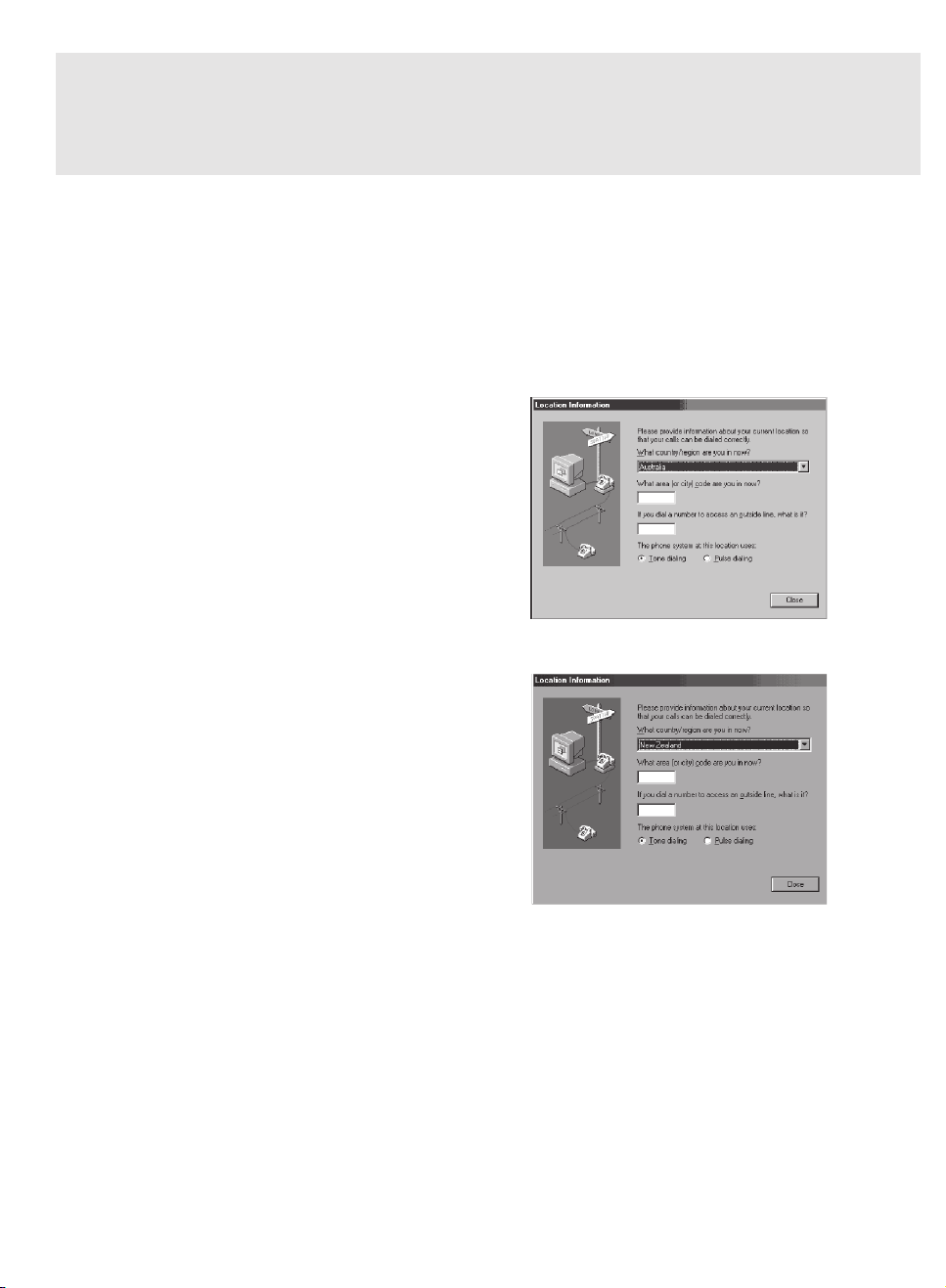
A. If you are located in Australia
1. Go to Control panel, select modem icon.
2. Choose Australia in “What country/region
are you in now?”
3. Select Phone system as “Tone Dialing”
4. Close
B. If you are located in New Zealand
1. Go to Control panel, select modem icon.
2. Choose New Zealand in “What country/
region are you in now?”
3. Select Phone system as “Tone Dialing”
4. Close
Page 6
Note: Modem setting in Windows XP
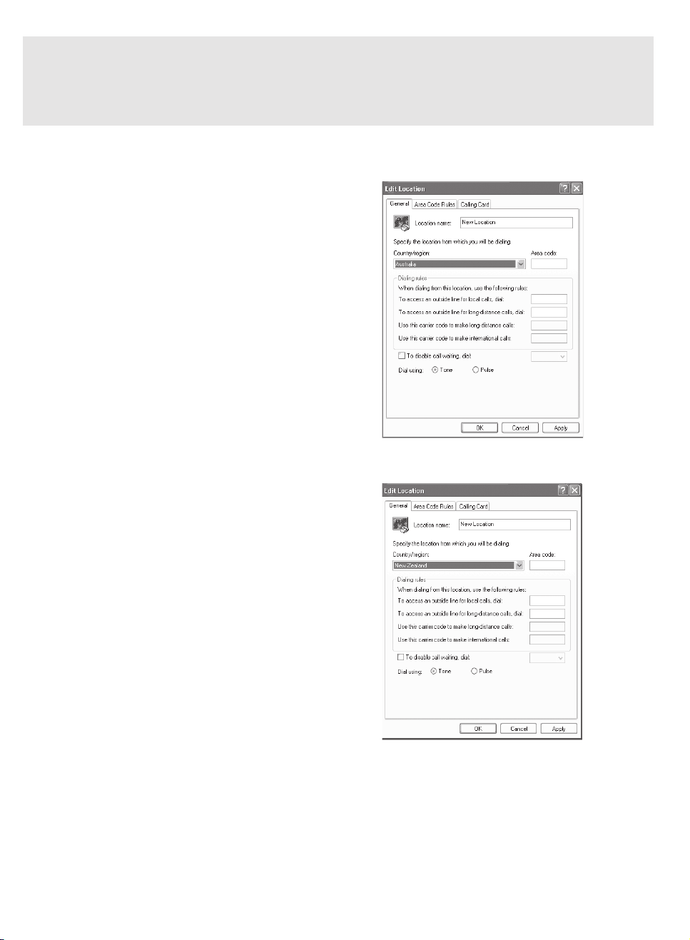
A. If you are located in Australia
1. Click Start select Control panel select "Phone and
Modem Options".
2. Double click New Location.
3. Choose "Australia" in Country/region pull down
menu bar.
4. Select Phone system as “Tone Dialing”.
5. Click OK and Apply.
B. If you are located in New Zealand
1. Click start select Control panel select "Phone and
Modem Options".
2. Double click New Location.
3. Choose "New Zealand" in Country/region pull down
menu bar.
4. Select Phone system as “Tone Dialing”.
5. Click OK and Apply.
Note:
The screens and illustrations shown in this examples may slightly vary depending on the operating
environment that you have installed.
Page 7
NOTATION IN THIS DOCUMENT
Warnings
This manual uses a variety of icons as visual marks so that you can use this computer safely and
correctly and avoid damage and danger to yourself and to others. These icons and their meanings
are as follows. Please learn these icons before reading this manual. Learning these icons will be
useful for understanding this manual.
Icon Meaning
WARNING
CAUTION
The symbols below are used together with the icons above to indicate what type of danger or
damage is involved.
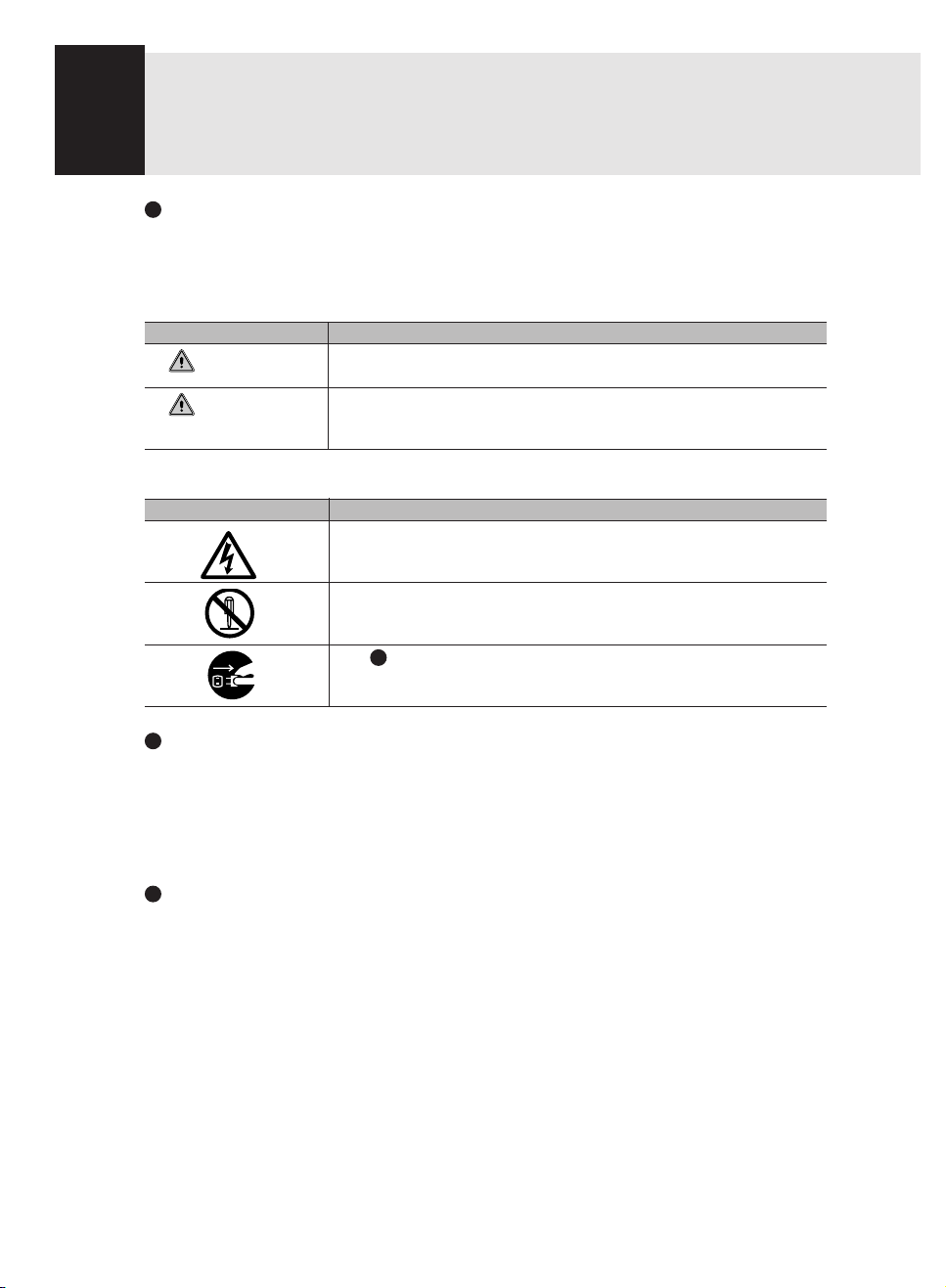
Symbol Meaning
Incorrect handling or ignoring this warning can cause a dangerous
situation that could result in death or severe injury.
Incorrect handling or ignoring this warning can cause a dangerous
situation that could result in moderate or minor injury or could result in
equipment damage.
The symbol indicates a w arning or caution. The symbol inside the
indicates the concrete nature of the warning. (The example on the left
is a caution for electric shock.)
The circle and slash indicates prohibited behavior. The symbol inside
the circle indicates the concrete nature of the prohibition. (The
example on the left indicates that disassembly is prohibited.)
The indicates instructions that must be followed. The symbol inside
indicates the concrete nature of those instructions. (The example on
the left tells you to unplug the power plug from the socket.)
Key notation and operation methods
Explanations of key operations do not show all the characters on the keyboard. Instead they
indicate just the keys necessary to the explanation as follows.
Examples: [Ctrl] key, [Enter] key, [ → ] key
When multiple keys are to be pressed at the same time, this is indicated by connecting them with
[+].
Examples: [Ctrl] + [F3] keys; [Shift] + [ ↑ ] key
Screen examples
The screens shown in this manual are examples. Please understand that the file names and
screens you use may be different.
Page 8
Notation in text
Here is what symbols in text mean.
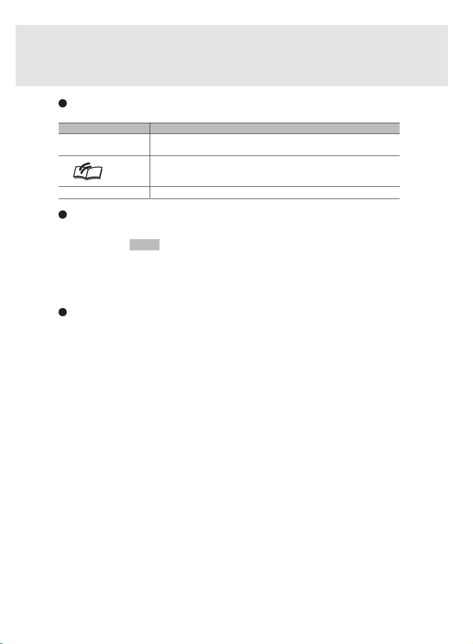
Symbol Meaning
Critical Points
Indicates a point necessary for correctly operating the hardware or
software.
Gives the meaning and brief explaination of a term.
Column
→ Indicates the page to see elsewhere in this manual.
Command input (key input)
Within the text of this manual, command input (giving commands to the computer by pressing
keys) is indicated as follows.
Example:
In the position indicated in the example above by the ↑, the space left between the characters
indicates that a space needs to be left in the entry by pressing the space bar (the long key with
nothing written on it at the center of the front of the keyboard). Commands are written in this
manual as lowercase latin letters, but uppercase letters may be used.
Product names
The following product names are abbreviated as follows in this manual.
“Microsoft® Windows XP® operating system” is written as “Windows XP”.
“Microsoft® Windows® 2000 operating system” is written as “Windows 2000”.
“Microsoft® Millennium® Edition operating system” is written as “Windows Me”.
“Microsoft® Windows® 98 operating system” is written as “Windows 98”.
“Microsoft® MS-DOS® operating system Version 6.2/V” is written as “MS-DOS”.
“Microsoft® Windows® operating system Version 3.1” is written as “Windows 3.1”.
“Microsoft® Windows NT® Server network operating system Version 3.5” and “Microsoft® Windows
NT® Workstation operating system Version 3.5” are both written as “Windows NT 3.5”.
“Microsoft® Windows NT® Server network operating system Version 3.51” and “Microsoft® Windows
NT® Workstation and NT Server Version 4.0” are both written as “Windows NT 4.0”.
“Windows NT 3.51” and “Windows NT 4.0” are both written as Windows NT.
“Fujitsu LifeBook” is written as “this computer” or “the computer main unit”.
dir c:
↑
Page 9

Configuration of this Manual
SECTION 1
This section explains basic operations and basic items for using this computer, including the
names of the parts and their functions, Flat Point Operations and battery operation.
SECTION 2
This section explains installation of options for this computer.
SECTION 3
This section explains what to do when trouble occurs with this computer and when messages are
displayed. Read this section as the necessity arises.
SECTION 1
SECTION 2
SECTION 3
Page 10

CONTENTS
SECTION 1
1. Names of the Parts and their Functions .............................2
2. Pointing Device.................................................................... 13
3. Keyboard ..............................................................................15
4. Switching on the Power ......................................................18
5. Switching off the Power ......................................................20
6. Suspend/Resume Function ................................................22
7. Battery ..................................................................................24
Front/Top ............................................................................................. 2
Left Side .............................................................................................. 5
Right Side ............................................................................................ 7
Rear/Bottom ........................................................................................ 8
Status Indicator LCD ......................................................................... 10
What Is the Flat Point? ...................................................................... 13
Flat Point Usage ................................................................................ 14
Keyboard ........................................................................................... 15
Numeric Keypad Mode ...................................................................... 15
Names of the Main Keys and their Functions .................................... 16
Switching on the power ..................................................................... 18
Precautions for Switching Off the Power ........................................... 20
Switching Off the Power .................................................................... 20
What Is the Suspend/Resume Function? .......................................... 22
Battery Charging ............................................................................... 24
Using PC with Battery ....................................................................... 25
Checking the Remaining Battery Charge .......................................... 26
Low Battery State .............................................................................. 27
Notes on Battery ................................................................................ 28
Replacing Internal Battery Unit ......................................................... 29
SECTION 2
1. Options................................................................................. 32
Options .............................................................................................. 32
Peripherals ........................................................................................ 33
2. PC Cards ..............................................................................34
Precautions for PC Cards .................................................................. 34
Installing PC Cards............................................................................ 36
Removing PC Cards .......................................................................... 37
3. Expansion RAM Modules ...................................................40
Installing an Expansion RAM Module ................................................ 41
Removing an Expansion RAM Module .............................................. 42
4. Multi-bay Unit .......................................................................43
Notes on using the multi-bay unit ...................................................... 43
Replacing multi-bay Unit.................................................................... 44
Loading/Ejecting disks ....................................................................... 45
Page 11

5. CD - ROM Drive ....................................................................46
Loading/Ejecting a CD - ROM ........................................................... 46
CD - ROMS ....................................................................................... 46
6. Floppy Disk Drive ................................................................48
Loading/Ejecting a Floppy Disk ......................................................... 48
What is a Floppy Disk? ...................................................................... 49
Precautions on Handling ................................................................... 50
7. Internal Data Fax Modem ....................................................51
Connection ........................................................................................ 51
8. Using Internal LAN ..............................................................53
Connection ........................................................................................ 53
9. Security Panel ......................................................................54
Security Panel Setup ......................................................................... 54
Passwords ......................................................................................... 54
Operate Your LifeBook Security Panel ............................................... 56
System Requirements ....................................................................... 57
Launching Applications with the Security/Application Panel ............. 59
E-Mail Notification LED ..................................................................... 59
Configuring your LifeBook Application Panel .................................... 59
Configure your E-mail Account Settings ............................................ 61
Using the Disc Player ........................................................................ 67
Desktop Control Panel....................................................................... 68
10. Mouse ...................................................................................70
Connecting PS/2 Mouse .................................................................... 70
Connecting USB Mouse .................................................................... 70
Disabling Flat Point............................................................................ 71
Using the Mouse ............................................................................... 72
11. Wireless Mouse ................................................................... 74
Precautions on safety ........................................................................ 74
Preparation and Preliminary knowledge ............................................ 76
Setup of personal computer and wireless mouse ............................. 77
Replacing batteries............................................................................ 78
For good maintenance....................................................................... 79
Caution .............................................................................................. 80
Troubleshooting ................................................................................. 80
Specifications .................................................................................... 81
SECTION 3
1. When This Happens ............................................................ 84
2. Care and Maintenance ........................................................88
3. Glossary ...............................................................................93
Page 12

SECTIONSECTION
SECTION
SECTIONSECTION
SECTIONSECTION
SECTION
SECTIONSECTION
11
1
11
11
1
11
SECTION 1
Page 13
SECTION 1
1.
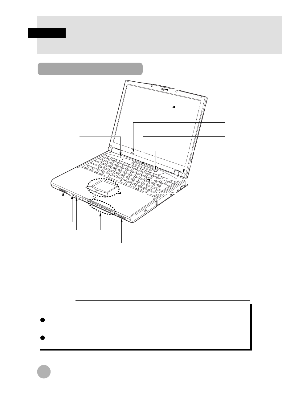
Names of the Parts and their Functions
Front/Top
1
2
3
#
0
!
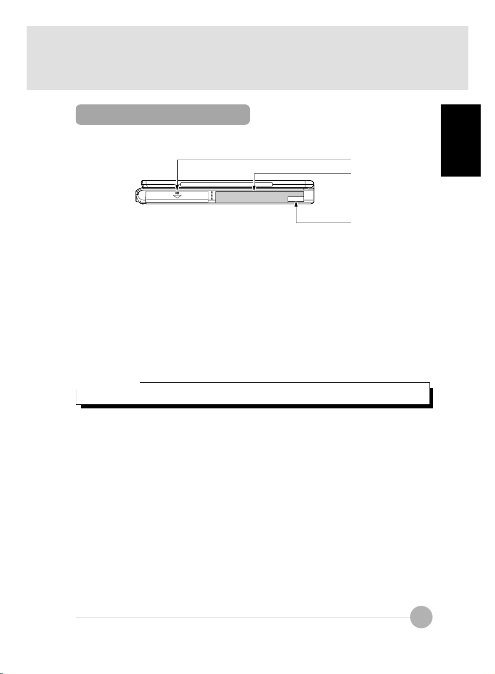
1 Latch
This latch locks the liquid crystal display (LCD) against unintended opening.
Unlock it to open the LCD.
2 Liquid Crystal Display (LCD)
Displays the screen of this PC.
Critical Point
Characteristic of LCD
The following natures are characteristic to LCD and you must not interpret them as defects.
The TFT color liquid crystal display (LCD) of this PC has more than 2.35 million pixels or dots
(in 1024 x 768 resolution) through the utilization of high-level technology. Because of this fact,
the display may contain some unlit or continuously lit dots.
The color tone of the LCD of this PC may differ among the units. And temperature change and
other cause may results in some uneven color tone.
@
9
4
5
6
7
8
2
Page 14
3 Built-in Microphone
You can record sound with this microphone.
Critical Point
You may experience feedback noise when you use music software and other software that
uses simultaneously the microphone and speakers. In this case, adjust the sound volume or
use a headphone or an external microphone available in stores. And set the microphone at
“mute” position when you do not use it.
Do not close the LCD when you use the built-in microphone to avoid feedback noise.
The recorded sound from the built-in microphone may not clear when the distance or the
direction of the sound source is not appropriate. We recommend you to use an external
microphone to record sound clearly.
4 Status Indicator LCD
This LCD displays the status of this PC.
5 SUS/RES Switch
This switch is used to turn on the power of the PC, to put it into suspend mode and to resume
working.
Critical Point
When you press down SUS/RES switch for 4 seconds or more when the power of this PC is
on, the power supply of this PC will power off.
6 Wireless Mouse Receiver (only for the models with a wireless mouse)
It receives the infrared signal from a wireless mouse (only for the models with a wireless mouse).
7 Keyboard
You can input characters and give commands to the PC unit through this device.
SECTION 1
8 Flat Point
You can manipulate the mouse pointer though this device.
9 Speakers
They output the sound from this PC unit.
CAUTION
HEARING LOSS
Turn the sound volume level of the PC unit to the minimum when you connect a headphone or
microphone, or it may cause device failure or undesirable influence to your audibility by
harmful noise.
! Mic-in Jack
It is the terminal to connect an external microphone to record sound (monaural, 3.5-mm mini
plug type). However, you cannot use some microphone in the market (ex. dynamic microphones).
Please check its connectivity before purchase.
3
Page 15
" Headphone Jack
It is the terminal to connect a headphone available in the market (3.5-mm mini plug type). However,
you cannot use some headphone if its type is not compatible. Please check its connectivity
before purchase.
CAUTION
HEARING LOSS
Be careful not to use a headphone at excessive volume level, or it might give adverse effect to
your audibility.
Do not turn on or off the power switch while you are wearing a headphone, or it might give
adverse effect to your audibility.
# Security / One-touch Buttons
These buttons are used to set/reset security lock, password input during power on or SUS/RES
of the PC unit, application start-up, incoming E-mail receiving and other functions.
$ Cover Close Switch
This switch is used to suspend/resume the function of this PC unit and to turn off the LCD back
light when you close or open the LCD display.
4
Page 16
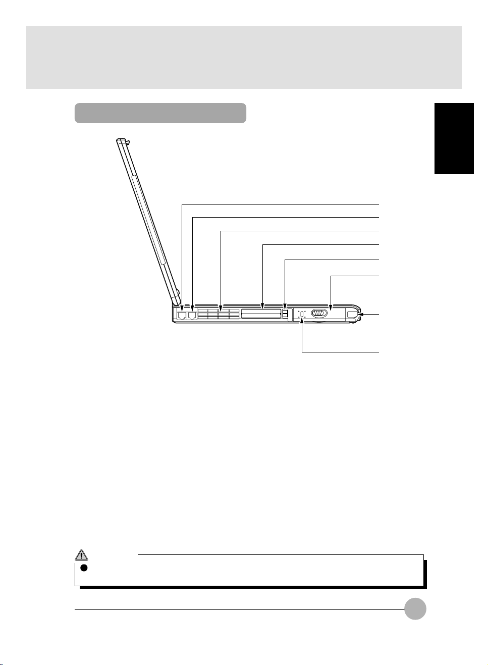
Left Side
SECTION 1
1
2
3
4
5
6
7
1 LAN Connector
Some models have a LAN connector to connect a LAN cable.
8
2 Modem Connector
Some models have a modem connector. This is the connector to connect the PC unit to telephone
line by a telephone cable to access Internet.
3 Air-Cooling Fan
It is a fan to let out the heat from the inside of the PC unit. It starts rotating when the temperature
of the inside of the PC unit is high.
4 PC Card Slots
They are the slots to insert PC cards sold separately.
The lower slot is Slot 1 and the upper slot is Slot 2.
5 PC Card Eject Button
You can eject a PC card from the PC unit by pushing this button.
See “Removing PC Card”.
CAUTION
Do not cover the holes over the air-cooling fan, or the heat inside the PC unit might cause the
machine failure.
5
Page 17

6 Internal Hard Disk
It is the detachable primary hard disk.
Critical Point
Some operating system calls Slot 1 as “Slot 0” and Slot 2 as “Slot 1”.
7 Infrared Communication Port (not supported by Windows NT)
It is the interface to conduct infrared communication.
Critical Point
Do not put an AC adapter or an external display near from the infrared communication port
when you are conducting infrared communication, or it cause malfunction due to noise from
those devices.
8 Anti-Theft Lock
You can connect an anti-theft cable available in the market to it.
Critical Point
This anti-theft lock is compatible with Micro Saver Security System from Kensington Ltd.
6
Page 18
Right Side
1
2
3
1 Internal Battery Unit
This unit acts as the power supply of this PC unit when you do not use an AC adapter.
See “Replacing Internal Battery Unit”.
2 Multi-Bay
One of the following devices has been installed depending on the model:
- Internal CD-ROM drive unit
- Internal DVD drive unit
- Internal CD-R/RW drive unit
- Internal floppy disk drive unit
- Multi-bay cover
Those units may be replaced.
See “Replacing Multi-Bay Unit”.
Critical Point
Do not use this PC unit when the multi-bay is empty, or it results in the unit failure.
3 Multi-Bay Unit Remove Lever
You can use this lever to remove the device unit installed in the multi-bay.
SECTION 1
7
Page 19
Rear/Bottom
1
2
3
4
5
6
7
9
8
0
8
Page 20

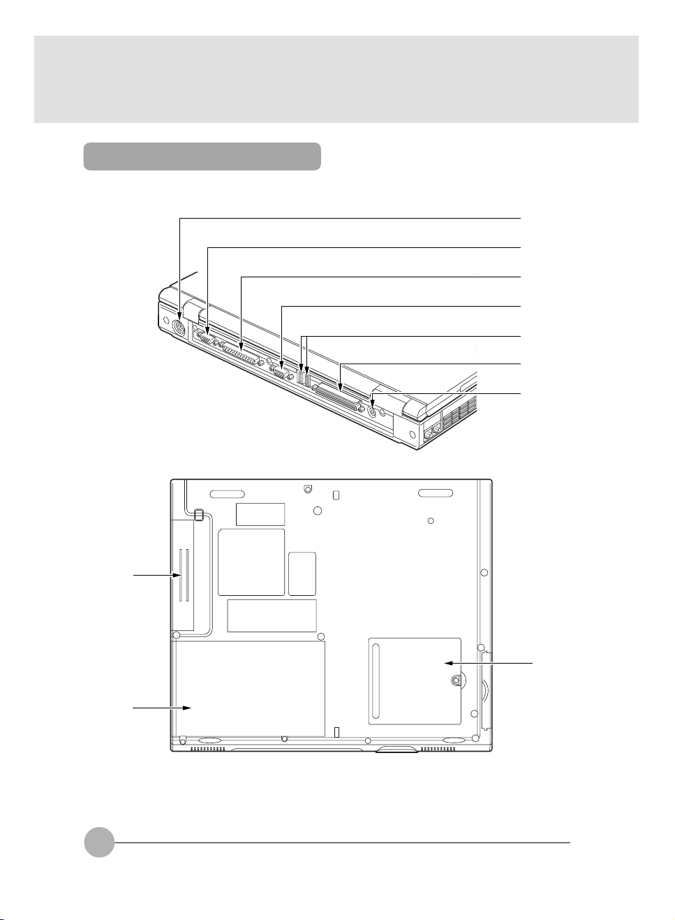
1 Expansion Keyboard/Mouse Connector
This is the connector to connect a PS/2 mouse and a numeric keyboard / keyboard.
2 Serial Connector
This is the connector to connect the devices with RS-232C interface sold separately.
3 Parallel Connector
This is the connector to connect a printer and other devices sold separately.
4 External Display Connector
This is the connector to connect a CRT display and other displays sold separately.
5 USB Connector (not supported by Windows NT)
You can connect a FDD unit, a printer and other USB standard peripherals to this connector.
There are 2 ports and you may connect a USB standard peripheral to either of the ports.
6 Docking Station Connector
This is the connector to connect a full docking station, a mini docking station and a port replicator.
7 DC-IN Connector
This is the connector to connect the AC adapter.
8 Expansion RAM Module Slot
This is the slot to install the memory unit of this PC.
9 Battery Bay
This is the bay to install the Battery.
! CD-ROM Drive Bay
This is the bay to install CD-ROM drive.
SECTION 1
Important note
When you connect an optional device to each connector, you must ensure the right direction
of the connectors and connect straight.
9
Page 21
Status Indicator LCD
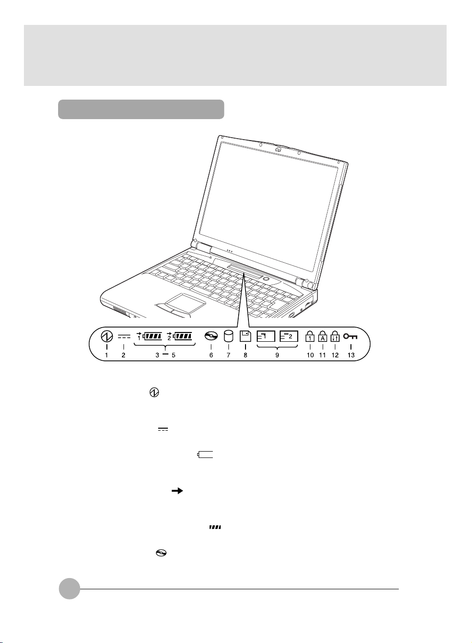
1 SUS/RES indicator ( )
This indicator appears up when this PC unit is functioning and blinks when the unit is in suspend
status.
2 AC Adapter Indicator ( )
This indicator appears when the power is supplied from AC adapter.
3 Battery Mounting Indicator ( 1, 2, )
This indicator appears when batteries are mounted. “1” means the internal battery and “2” means
the auxiliary battery in mobile multi-bay.
4 Battery Charge Indicator ( )
This indicator appears when batteries are charged. And it blinks when battery charge is not in
progress because the batteries are too hot or too cold.
5 Remaining Battery Power Indicator ( )
This indicator indicates the remaining battery power.
6 CD Access Indicator ( )
This indicator appears when a CD is accessed. See also POINT below.
10
Page 22
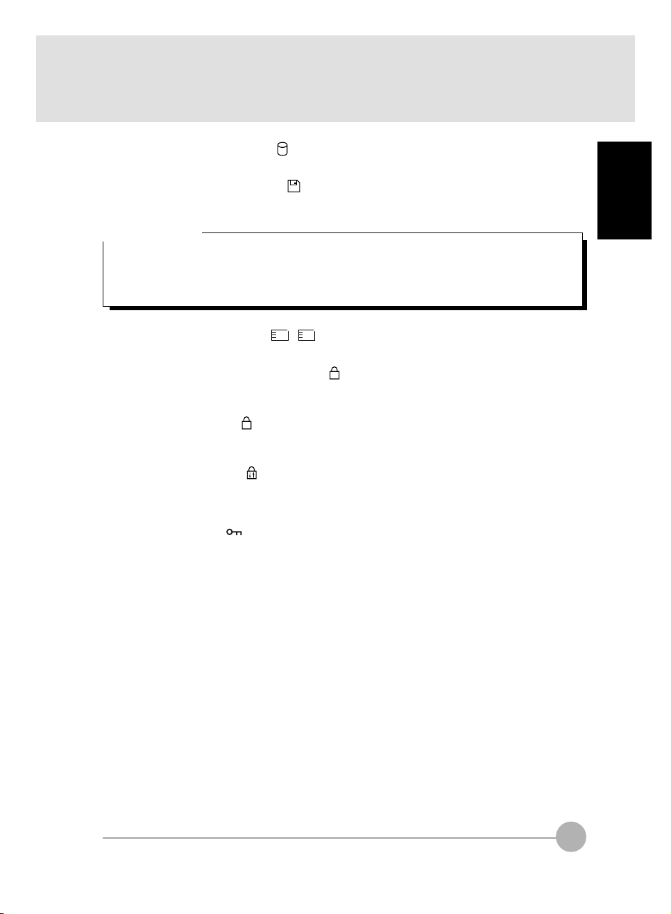
7 Hard Disk Access Indicator ( )
This indicator appears when the internal hard disk is accessed. See also POINT below.
8 Floppy Disk Access Indicator ( )
This indicator appears when a floppy disk or a super disk is accessed. See also POINT below.
Important note
When you connect a FDD unit (USB), the floppy disk access indicator in the status indicator
LCD does not appears even a floppy disk is accessed. You should check the access to the
floppy disk with the access lamp on the FDD unit (USB). Make sure that the access lamp does
not light up when you eject a floppy disk.
SECTION 1
9 PC Card Access Indicator (
This indicator appears when a PC card is accessed. See also POINT below.
! Num Lock (Numerical Lock) Indicator (
This indicator appears when the keyboard is set to numeric keypad mode. You can set and reset
the numeric keypad mode by pressing the [Num Lk] key.
" Caps Lock Indicator (
This indicator appears when English capital mode is set (to input English capital letters). You can
set and reset the English capital mode by pushing down the [Caps Lock] key.
1 2
)
)
1
)
A
# Scroll Lock Indicator ( )
This indicator appears when scroll lock is set to avoid screen scrolling. You can set and reset the
scroll lock by pushing down the [Scr Lk] key while pressing down the [Fn] key.
The function depends on the application when this indicator appears.
$ Security Indicator ( )
This indicator appears when security function is on. You must input password if the security
indicator show on the status indicator lcd when you power on or wake-up from sus/res function.
11
Page 23

Critical Point
If you operate SUS/RES switch while the hard disk access indicator or the floppy disk access
indicator appears, the data on the hard disk, floppy disk or super disk may be corrupted.
Some operating system calls Slot 1 as “Slot 0” and Slot 2 as “Slot 1” in the PC card access
indicator.
Windows 98 / Windows Me tries to detect the existence of a CD periodically if CD auto insert
function is on. This causes periodical indication of the CD access indicator in the status indicator LCD. You can set up as followings to disable this auto insert function (This setting only
applicable on Windows 98 and Windows Me):
1 Click on the Start ->Settings -> Control Panel.
2 Click on the System icon
3 Click on the Device Manager tab.
4 Double-click on the “CD-ROM”.
CD-ROM device is indicated.
5 Click on the CD-ROM device and then click on the Properties.
The Properties of CD-ROM Device dialog box appears.
6 Click on the Setting tab.
7 Click on the “Auto notification of insertion” in Option to set it disabled.
8 Click on OK.
9 Click on OK or Close in the System Property dialog box to go back to the Control
Panel window.
10 Restart the PC unit.
To enable auto notification, click on “Auto notification of insertion” in step 7 to put
check mark on it.
12
Page 24
SECTION 1
2. Pointing Device
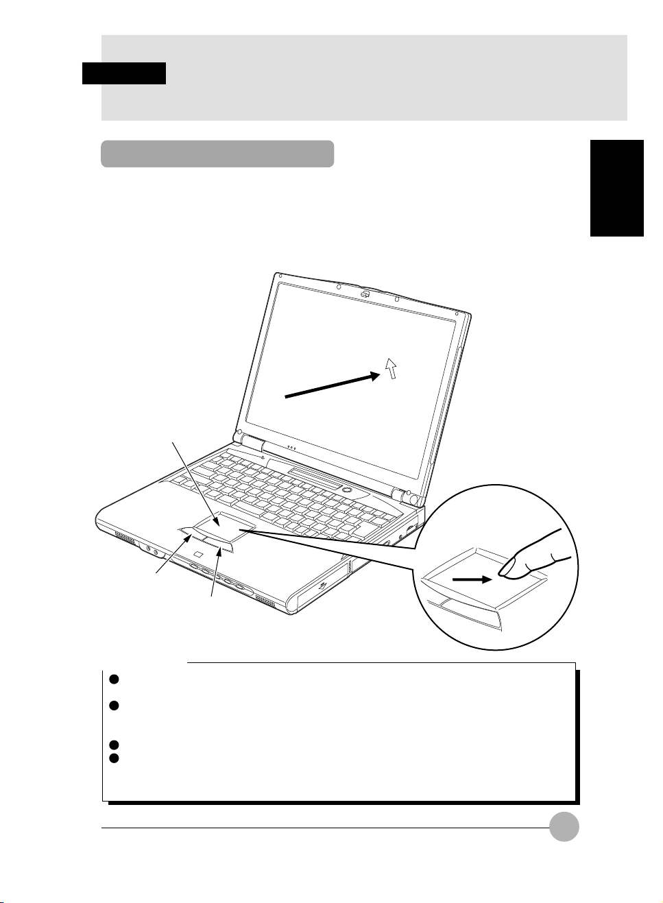
What Is the Flat Point?
Flat point is a convenient pointing device with which you can manipulate mouse pointer with your
finger movement. It is composed of a touchpad and 2 buttons.
The touchpad carries the function of a ball in a mouse. You can move the mouse pointer on the
screen by sliding your fingertip on its surface upward, downward, leftward and rightward. And by
tapping its surface, you can also realize click, double-click, point, drug and other functions.
The left and right buttons are equivalent to the left and right button on a mouse. Their functions differ
for each application.
Touchpad
SECTION 1
Left button
Right button
Critical Point
The pointer movement of a flat point may differ a little due to the difference of the dryness of
the finger tip of a user and other reasons.
Dew drop and dirt on the touchpad may result in malfunction. In such a case, remove dew and
dirt from the surface by wiping with dry soft cloth. And when the surface is excessively dirty,
remove the dirt by wiping with a soft cloth soaked with diluted neutral detergent.
When you want to use a PS/2 mouse.
When you use a mouse, it is necessary to set Keyboard / Mouse Set Up in the BIOS setup for
the simultaneous use with the flat point and other options.
13
Page 25
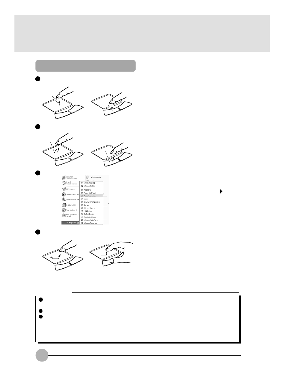
Flat Point Usage
Click Clicking means to tap the touchpad once or to
Double click Double-clicking means to tap the touchpad twice
Point
Drag Dragging means to move the mouse pointer to
push the left button once and release it at once.
And “right click” means to push the right button
once.
consecutively or to push twice the left button
quickly and release at once. The speed of doubleclick can be adjusted in the Mouse Properties
dialog box.
Pointing means to set the mouse pointer over
menu and other icons on the screen. When you
set the mouse pointer on a menu and if the menu
has sub-menu under it (indicated with mark on
the right end of the menu), the sub-menu appears.
your favorite place and tap the touchpad twice
quickly. In the second tap, you must not release
your fingertip from the surface and move it to the
appropriate position, then release your fingertip.
Or you may move the mouse pointer to your
favorite position and move your finger tip on the
surface of the touchpad with holding down the
left button, then release your finger tip.
Critical Point
The manipulations explained above are applicable when you set “For a right-handed person”
in the Mouse Properties dialog box.
You must tap lightly and quickly with your fingertip. It is not necessary to press down strongly.
The mouse pointer on the screen do not move if you lift your fingertip up and bring down it on
the different position while you are moving the mouse pointer on the flat point. When you put
down and move your fingertip on the touchpad, the pointer moves in the direction of your
fingertip movement from that position.
14
Page 26
SECTION 1
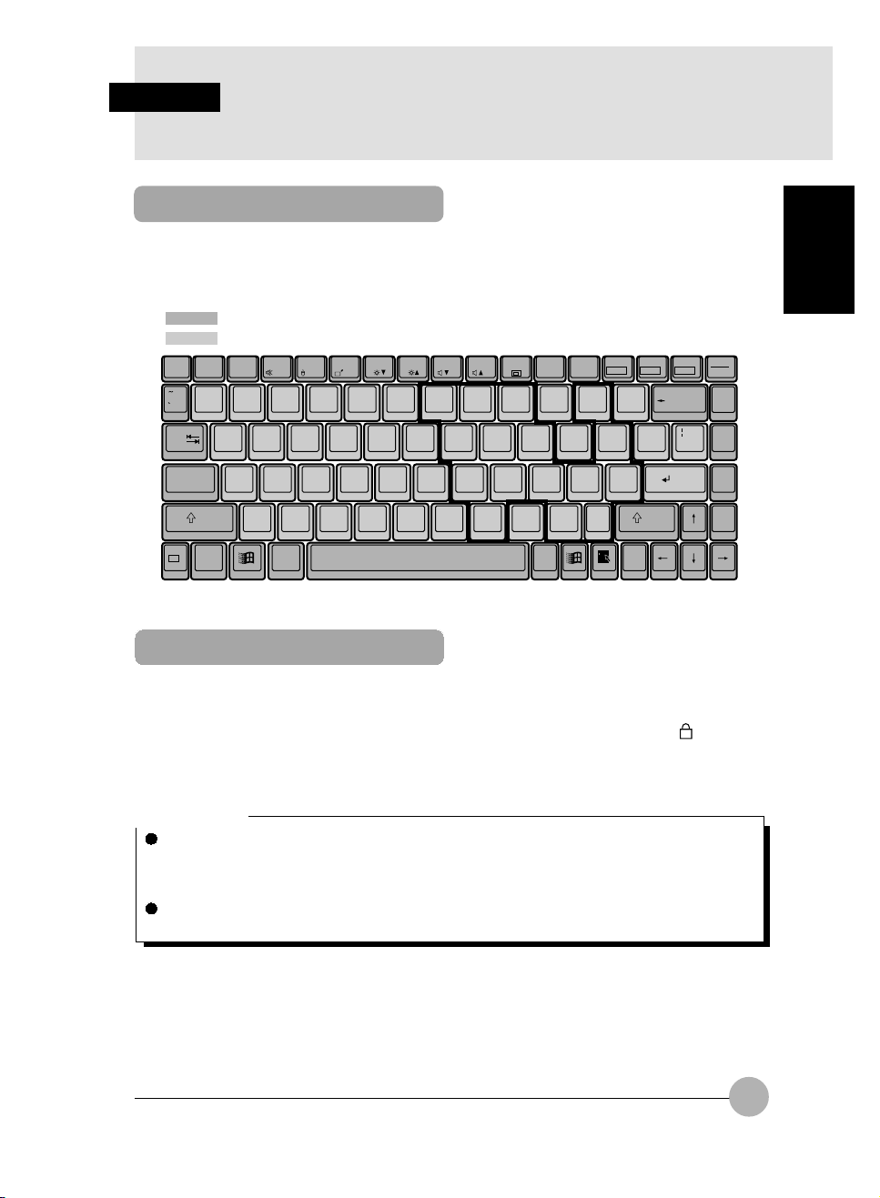
3. Keyboard
Keyboard
The keyboard is the device for giving instructions to the computer, inputting data, and executing. The
keys can be divided into two types.
Control keys
Character keys
Num Lk
Insert
Delete
F1Esc F2 F3 F4 F5 F6 F7 F8 F9 F10 F11 F12
_
@
!
12
QWER T Y UI OP
Tab
CapsLock
Shift Shift
Fn
Ctrl Alt
#3$4%5^
ASDFGHJ KL
ZXCVBNM<,>
&
67
789
456
*8(
123
0
)
90
.
.
Alt Ctrl
-
-
:
;
+
/
Scr Lk
Prt Sc
+
=
{
}
[
]
Enter
"
'
*
?
/
SysRq
Backspace
\
Enter
Pause
Break
SECTION 1
Home
Pg Up
Pg Dn
End
Numeric Keypad Mode
The mode in which some of the character keys are used as numeric keys (with a key layout that
makes numeric input easier) instead of their normal functions is called numeric keypad mode. The
keyboard is switched to numeric keypad mode with [Num Lk]. (In numeric keypad mode, 1 is displayed
on the status indicator LCD.) The keys surrounded by thick lines in the diagram above become the
numeric keypad. The numbers input with these keys are printed in front of each key.
Critical Point
When the separately sold numeric keypad is connected, if you press [Num Lk] to put the
computer into numeric keypad mode, the keys on the external numeric keypad are enabled,
but the numeric keypad section on the keyboard is disabled.
For Thailand keyboard, the functions keys F8 and F9 is the same function as the English
keyboard to lower and increase the speaker volume.
15
Page 27

Names of the Main Keys and their Functions
[Esc] (escape) key
The usage is determined by the application software. It is often used to return to the previous
operation.
[F1]-[F12] (function) keys
The usage depends on the application software.
[Fn] key
A key unique to this computer; it has the following functions.
[Fn] + [F3] This switches ON/OFF of the speaker.
[Fn] + [F4] This select to disabled the touch pad mouse when you attached an external
[Fn] + [F5] This select whether or not to use the entire LCD screen for display in text
[Fn] + [F6] Turns down the backlight of the LCD.
[Fn] + [F7] Turns up the backlight of the LCD.
[Fn] + [F8] This select to lower down the volume of the speaker.
[Fn] + [F9] This select to increase the volume of the speaker
Critical Point
Luminance of the backlight of the LCD can be turned up (with [Fn] + [F7] keys) or turned
down (with [Fn] + [F6] keys) in three degrees.
When a pip sounds with this operation, the speaker is on. When nothing
sounds, the speaker is turned off.
mouse.
mode.
[Fn] + [F10] Rotates among the three display options: LCD only, CRT only, both LCD
[Fn]+SUS/RES switch
Space key Inputs a single space character.
[↑][↓][←][→] (cursor) keys
and CRT.
Activates the Save To Disk function.
(This is the long key with nothing written on it at the center of the front of the
keyboard.)
Move the cursor.
16
Page 28

[Enter] key
Also called the return key or the line feed key. This key inputs line feeds and executes command.
[Ctrl] key
Used in combination with other keys; its functions depend on the application software.
[Shift] key
Used in combination with other keys.
[Alt] key
Used in combination with other keys; its functions depend on the application software.
[Caps Lock] key
To lock the keyboard into caps mode, press this key, pressing this key again ends caps
mode.
[Num Lk] (numerical lock) key
Press this key to put the computer into numeric keypad mode.
[Scr Lk] (scroll lock) key
Its functions depend on the application software.
[Print Screen] key
Press this key to make a hard copy of the screen.
[Pause] key
Press this key to pause the screen display.
[Break] key
Its functions depend on the application software.
[Insert] key
Press this key to insert a new character between characters. The new characters are entered
at the cursor position.
[Delete] key
Press this key to delete a character. Pressing the Delete key and the Ctrl and Alt keys at the
same time resets this computer.
[Home] key
Press this key to move the cursor directly to the head of the row or the head of the document.
[End] key
Press this key to move the cursor directly to the end of the row or the end of the document.
[Pg Up] key
Press this key to switch to the previous screen.
[Pg Dn] key
Press this key to switch to the next screen.
[Back Space] key
Press this key to delete the character to the left of the cursor position.
[Sys Rq] (system request) key
When this key is supported by the application software, this key is used for such functions as
resetting the keyboard. Press this key together with the Fn key.
[ ] (Windows) key (only valid for Windows 98 / Windows Me and Windows XP)
Press this key to display the Start menu.
[ ] (Application) key (only valid for Windows 98 / Windows Me and Windows XP)
Press this key to display the shortcut menu for the selected item. This key has the same role
as the mouse right click.
SECTION 1
17
Page 29
SECTION 1
4. Switching on the Power
Switching on the power
This item explains the normal way to switch the computer main unit power on.
Critical Point
After you put on the power, do not bring the PC unit or give shock or vibration. They may result
in machine failure.
If a disk is inserted in the floppy disk drive or the super disk drive, remove it before you put on
the power.
Do not put on the power when there is no device installed in the multi-bay. It may results in
machine failure.
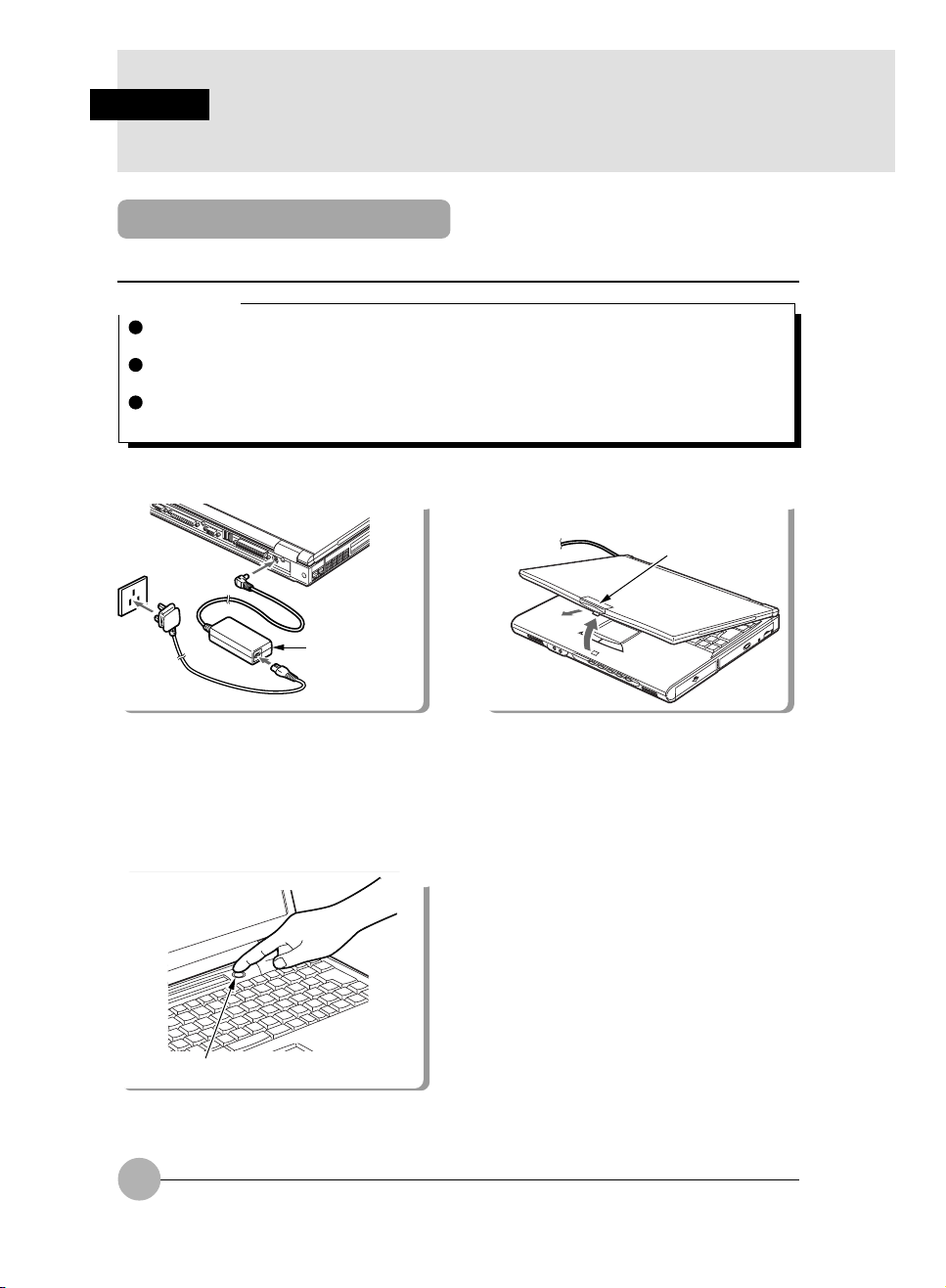
1 Connect the AC adaptor.
2
3
AC adaptor
1
First connect the AC power cord to the AC
adaptor (1), next connect the other cord of
the AC adaptor to the personal computer’s DCIN connector (2). Lastly, plug the AC power
cord into an AC outlet (3).
3 Push SUS/RES switch.
2 Open the LCD panel.
Latch
Push the latch to release the lock, then lift the
display panel with your hand.
SUS/RES switch
The PC is powered on and POST is started.
And the status indicator LCD is activated.
18
Page 30

Critical Point
POST is the abbreviation of “Power On Self Test”, a self-diagnosis test to check if there is any
abnormality in the PC. This test is automatically carried out when the power of this PC unit is
on and completed right before the start-up of operating system.
SECTION 1
19
Page 31

SECTION 1
5. Switching off the Power
Precautions for Switching Off the Power
This item explains how to switch off the power and gives precautions for switching off the
power.
The following precautions must be observed when switching off the power.
When you power off and power on again the system, wait for about 10 second before you
power on.
Switching Off the Power
Windows XP
1 Click Start.
2 Click Turn Off Computer.
3 Click Turn Off.
4 The system will shut down and power off.
Windows Me or Windows 98
1 Click on Start -> Shut Down.
The Shut Down Windows dialog box appears.
2 In Windows Me, select “ Shut down” and click OK.
In Windows 98, select “Shut down” and click OK.
Critical Point
You can restart this PC by selecting “Restart” in the dialog that appears in Step 1. Restart
means to erase the information on the memory once and reload an operating system from a
floppy disk or a hard disk.
If you select “Stand-by” in the dialog that appears in Step 1, this PC unit enters energy conserve
mode.
If you will not use this PC for a longer period, remove the AC adapter and batteries.
20
Page 32

Windows 2000
1 Click on Start -> Shutdown.
The Shut down Windows dialog box appears.
2 Select Shutdown and click on OK.
The power automatically goes off.
Critical Point
You can restart this PC by selecting “Restart” in the dialog displayed in Step 1. Restart means
to erase the information on the memory once and reload an operating system from a floppy
disk or a hard disk.
If you select “Stand-by” or “Idle status” in the dialog appears in Step 1, this PC unit enters
energy conserve mode.
You can switch off the power by the following steps:
1 Push the [Delete] key down while pressing down the [Ctrl] and [Alt] keys. The Windows
Security dialog box appears.
2 Click on Shutdown.
The Windows shutdown dialog box appears.
3 Select Shutdown and click on OK.
The power automatically turns off.
If you will not use this PC for a longer period, remove the AC adapter and batteries.
Windows NT
1 Click on Start -> Shutdown.
The Windows Shutdown dialog box appears.
2 Make sure that “Shutdown computer” is selected and click on Yes.
( ) in the status indicator LCD turns off and the power of this PC unit automatically turns off.
Critical Point
In some cases, “It is now safe to turn off your computer.” messages appears, but the power
does not turn off automatically. In such a case, press SUS/RES switch down for 4 seconds or
more.
You can restart this PC by selecting “Restart computer” in the dialog displayed in Step 2.
Restart means to erase the information on the memory once and reload an operating system
from a floppy disk or a hard disk.
You can also turn off the power through the following steps:
1 Push down the [Delete] key while pressing down the [Ctrl] and [Alt] keys.
2 When the Windows NT Security dialog box appears, click on Shutdown.
3 When Shutdown the Computer dialog box appears, select “Turn off after shutting down”
and click on OK. Power automatically turns off.
If you will not use this PC for a longer period, remove the AC adapter and batteries.
SECTION 1
21
Page 33

SECTION 1
6. Suspend/Resume Function
What Is the Suspend/Resume Function?
When this computer is suspended with the SUS/RES switch, the suspend/resume function retains
the programs and data in memory as it is that you can resume operations immediately the next time
you press the SUS/RES switch.
Critical Point
With resetting, the data in memory will be lost. Save the necessary data before resetting.
If you cannot reset through the following procedure, press down SUS/RES switch for 4 seconds
or more so that you can turn off the power of the PC unit. Then, wait for about 10 seconds and
push down SUS/RES switch again.
Windows XP
1 Click Start.
2 Click Turn Off Computer.
3 Click Restart.
4 The system will restart.
Windows Me or Windows 98
1 Click on Start -> Shut Down.
The Shut Down Windows dialog box appears.
2 Select “Restart” for Windows Me / Windows 98 and click on OK.
This PC unit is reset.
Critical Point
If you cannot reset through the above-mentioned procedure, you can reset as followings:
1 Push down the [Delete] key while pressing down the [Ctrl] and [Alt] keys.
When the Terminate Application dialog box appears, follow the instructions.
Window 2000
1 Click on Start -> Shut down.
The Shutdown Windows dialog box appears.
2 Select “Restart” and click on OK.
Critical Point
You can reset as followings:
1 Push down the [Delete] key while pressing down the [Ctrl] and [Alt] keys. The Windows
Security dialog box appears.
2 Click “Shutdown”.
The Shutdown Windows dialog box appears.
3 Select “Restart” and click on OK.
This PC is reset.
22
Page 34

Windows NT
1 Click on Start -> Shutdown.
The Shutdown Windows dialog box appears.
2 Select “Restart computer” and click on Yes.
This PC is reset.
Critical Point
You can reset as followings:
1 Push down the [Delete] key while pressing down the [Ctrl] and [Alt] keys.
2 When the Windows NT security dialog box appears, click “Shutdown”.
3 When the Shutdown the Computer dialog box appears, select “Restart after Shutdown and
click on OK. This PC is reset.
SECTION 1
23
Page 35

SECTION 1
7. Battery
Battery Charging
This PC is capable to supply power from batteries as well as the AC adapter.
1 Connect the AC adaptor.
2
3
First connect the AC power cord to the AC
adaptor (1), next connect the other cord of
the AC adaptor to the personal computer’s
DC-IN connector (2). Lastly, plug the AC
power cord into an AC outlet (3).
2 Make sure that the battery charge indicator disappears and disconnect the AC adapter.
AC adaptor
1
Critical Point
Charge battery when you start using this PC after purchase or if you have not charged it for
more than 1 month.
The battery charge is completed when the battery charge indicator disappears and the
remaining battery power indicator changes from blinking to appearing. Take sufficient time for
battery recharge to make sure that the battery is fully charged.
When the remaining battery power is still 90% or more, the unit does not start charging even
though the AC adapter is connected. Charging starts when the power is 89% or less.
The battery charging capability deteriorates when room temperature is too high or too low.
Battery protection function may prevent the battery charging when battery temperature is too
high after usage ( ). However, charging starts when the battery temperature lowers after
a while.
If you attached an auxiliary battery, both of batteries are charged simultaneously.
24
Page 36

Using PC with Battery
This item explains operation with the battery.
1 Disconnect the AC adaptor and switch
on the main switch.
When the battery fully charge, remove
the AC Adaptor and power on your system. Now your system operate in battery
mode.
SUS/RES switch
Press the main switch in the direction of the
displayed.
Critical Point
When the room temperature is low, the battery operation time length becomes shorter.
When the battery has been used for a longer period, the battery operation time length becomes
shorter. If you notice that the operation time length becomes extremely short, replace the
battery with a new one.
When you attach an auxiliary battery, both of the batteries are used simultaneously.
SECTION 1
25
Page 37

Checking the Remaining Battery Charge
This computer indicates the amount of battery charge remaining with the remaining battery
charge indicator on the status indicator LCD.
Remaining battery charge indicator
Indicates battery charge level of about 76% to about 100%
Indicates battery charge level of about 51% to about 75%
Indicates battery charge level of about 26% to about 50%
Indicates battery charge level of about 16% to about 25%
Indicates the low battery state (battery charge level of about 15% or lower). The warning
beeps and flashes.
Indicates that the battery has run out (0% charge level).
Critical Point
Indication of the remaining battery charge indicator ( ) may be slightly different from the
real remaining charge rate depending on the operating environment (temperature, number of
times that the battery was previously charged and discharged, etc.) because of the
characteristic of the battery (lithium ionic battery).
When there is 90% or more of the battery capacity remaining in the battery after the AC
adapter is disconnected, the battery won’t be charged. Charging the battery starts when its
remaining power drops to 89 % or less of the capacity.
“1” in the battery mounting indicator means the internal battery.
Battery abnormality indicator
Indicates that the battery can not be charged normally.
Critical Point
When ( ) blinks, turn off the power of the PC unit and reinstall the battery. When the
blinking persists, the battery is defective. Replace it with a new battery.
26
Page 38

Low Battery State
Here is the explanation on the indication when the battery of this PC enters in low battery
status and the countermeasure against it.
Low Battery Status Indication
The remaining battery power indicator blinks in the status indicator LCD.
Critical Point
Alarm sounds when the unit with Windows NT becomes low battery state. However, this
alarm may not be audible if sound volume level is set low.
Alarm sound is not audible if speaker is turned off.
Speaker is turned On/Off by pushing the [F3] key while pressing down the [Fn] key. A sound
like whistle means that the speaker is turned on and silence means that it is turned off.
Counter measure against Low Battery Status
1 Connect the AC adapter.
The battery is charged with the connection of the AC adapter.
Critical Point
If you continue operating the PC under the low battery status, data might be lost during your
operation while creating or saving it in the worst case. Connect the AC adapter immediately.
And if the AC adapter is not available, save the working data, close the applications in use
and turn off the power of the PC.
The read and write function to the hard disk consumes a lot of power. Use the AC adapter to
save data to the hard disk under low battery status.
If you leave the PC unit under low battery status, it enters suspended status automatically.
However, the unit will not be suspended before the completion of the data read and write
function to hard disk.
Windows XP is preset to enter standby mode automatically when the remaining battery level
becomes low. Do not change the settings in the following items under Power Options Properties.
Low battery alarm:
• Activate low battery alarm when power level reaches 10% is default setting. Under Alarm
Action you can set the setting of low battery alarm actions.
Critical battery alarm:
• Activate critical battery alarm when power level reaches 3% is default setting. Under Alarm
Action you can set the setting of critical battery alarm actions.
If you use your computer with these items unchecked ( ), the power will be immediately shut
down when the battery becomes dead and unsaved data will be lost. It could also lead to a
system failure.
Windows 2000 and Windows 98 / Windows Me automatically suspend the PC when the
remaining battery power lowers to 3%. Do not change the following settings in the Alarm tab
in the Power Option Properties dialog box:
•“Activate critical battery alarm when power level reaches”
• The following items in “ Low battery alarm “ dialog box that appears with the click on “Alarm
action”.
•“When the alarm goes off, the computer will” in “Stand by”
•“Force standby or shutdown even if a program stops responding”
If those items are checked by clicking, the power is on until the battery is completely exhausted and the working data will not be saved. And this might result in the machine failure of
the PC unit.
SECTION 1
27
Page 39

Notes on Battery
WARNING
ELECTRIC SHOCK
Always turn off the computer main unit main switch and disconnect the AC adaptor
before installing/removing the Built-in battery pack in order to avoid electric shock.
Discharge
• We recommend to charge a battery just before its use because it gradually discharge little by
little even though you do not use it after charging.
• Remove the battery and store it in a cool place if you are not going to use this PC for a longer
time (about 1 month or more). The battery discharges excessively and it results in the shorter
battery life if it is left inside the PC for a longer period.
Battery Life
• The battery is deteriorating even when you do not use the PC unit for a longer period. Use the
PC unit with the battery once a month to check the battery condition.
• Because the battery is consumable item, its charging capacity deteriorates after a longer usage.
• When the battery power duration becomes excessively short, it means that the battery life
ends.
Battery Disposal
When you dispose the battery, insulate the battery terminal with tape to avoid electric short and
dispose it in the accordance to the local government ordinances and rules.
To Prolong the Battery Life
Use power saving feature.
When the battery operating time becomes shorter
• The battery operating time is effected by the room temperature. Low temperature might result
in the shorter battery operating time.
• When you use the battery for a longer time, its recharging capacity deteriorates. Replace with
a new one in such a case.
Use the AC adapter in the following cases
• When you use the hard disk, a CD, a super disk frequently.
• When you use LAN and the modem frequently.
• When you set the PC status back to the original condition upon purchase.
28
Page 40

Replacing Internal Battery Unit
The replacement of the internal battery unit must be done after saving programs and data to
the hard disk or other storage devices. Here is the replacement of the internal battery unit.
WARNING
ELECTRIC SHOCK
Make sure to turn off the power of the PC unit and remove the AC adapter before you
replace the battery unit. And do not touch the connectors on the PC and battery
units, or it leads to electric shock and machine failure.
1 Turn off the power of the PC unit and remove the AC adapter.
SECTION 1
2 Slide upward the cover of the internal
battery unit.
3 Slide the internal battery unit to the
outside.
Battery unit
The internal battery unit is removed from the
connector.
Connector
29
Page 41

4 Remove the internal battery unit.
5 Install a new battery unit
Battery unit
Pull up the internal battery unit shown above
and remove it.
6 Connect the connector
Slide the battery unit inside and connect the
connector while the battery unit cover is kept
open.
Battery unit
Install a new battery unit so that the projection
on the PC unit and the slit on the battery unit
align together.
7 Slide the cover
Lock the cover that was once slid open in
Step 2.
Slit
30
Page 42

SECTIONSECTION
SECTION
SECTIONSECTION
SECTIONSECTION
SECTION
SECTIONSECTION
22
2
22
22
2
22
SECTION 2
Page 43

SECTION 2
1. Options
Options
FDD unit (USB)
PC card
USB mouse *1
External display
Printer
Keyboard
Mouse
Numeric keypad
Internal floppy disk drive unit
Memory
Internal battery unit
Internal CD-ROM drive unit
Internal CD-R/RW drive unit
Internal DVD-ROM drive unit *1
Internal hard disk unit
*1 supported only by Windows XP, Windows 2000 and Windows 98 / Windows Me.
32
Page 44

Peripherals
Before connecting peripherals, please read the following:
Use the peripherals that conform to ACPI standard
This PC is set to ACPI mode for Windows XP, Windows 2000 and Windows 98 / Windows Me.
Power save and other functions may not work correctly if a peripheral does not conform to ACPI
mode.
Notes on installation/removal
The installation of the peripheral must be done after the setting up of an operating system except
for a PS/2 mouse. The set-up function might not complete correctly if such a peripheral is attached
before the operating system set up.
Critical Point
When you connect a peripheral to a connector, make sure that the direction of the connection
is correct and connect straight.
When you connect more than one peripherals, complete setting for each peripherals before
installing others.
SECTION 2
33
Page 45
SECTION 2
2. PC Cards
Precautions for PC Cards
Make sure the following points in using PC card to avoid failure.
Do not place PC cards in hightemperature locations and locations subject to direct sunlight.
Do not place heavy objects on
top of PC cards.
Do not subject PC cards to
strong shocks.
Be careful to avoid spilling coffee
and other liquids on PC cards.
Avoid rubbing PC cards and
building up static electricity.
When storing a PC card, always
place it in its special case.
34
Page 46
Critical Point
The examples of common PC card are as followings:
• SCSI card
It is the PC card required connecting a hard disk, an MO (Magneto Optical disk) drive and
other SCSI-standard devices.
• LAN card
It is the PC card required connecting PCs to share data and a printer.
A certain PC card does not allow using 2 cards simultaneously. Those cards are seen among
LAN card, modem card and other communication cards. Check the document for the PC card.
And some PC card may not be used with this PC unit.
This PC unit does not support PC cards that require 12V-power supply.
SECTION 2
35
Page 47
Installing PC Cards
PC card is a generic term for business card sized cards which have a program and data
memory function or peripheral equipment functions such as a modem or LAN adaptor. This
item explains how to install a PC card.
CAUTION
INJURY
When you set a PC card, do not insert your finger into the PC card slot. It may cut your
fingertip.
Critical Point
Some PC cards require shutting down regardless of the type of your operating system or
require the installation of a device driver. Consult with the documentation of the PC card.
1 In the case of Windows NT, turn off the power of the PC unit and remove the AC adapter.
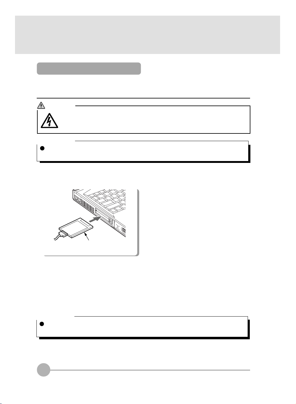
2 Set the PC card.
PC card
Insert the PC card firmly into the PC card
slot with the product name of the PC card
upward.
3 In the case of Windows NT, attach the AC adapter and turn on the power of PC unit .
4 If you are setting the PC card for the first time, install its driver, if necessary.
Some PC cards require the installation of their driver. Consult with the documentation of the PC
card to install the driver. A floppy disk and CD may be necessary for the driver installation.
Critical Point
Do not put anything on the connector that connects the PC card and a cable and handle it
carefully, or it results in machine failure.
36
Page 48

Removing PC Cards
Here is the explanation on how to remove a PC card in various operating systems.
Critical Point
Do not remove a PC card by double-clicking the PC Card icon on task bar or by clicking on
Stop in the Property of PC Card (PCMCIA) dialog box which appears by the click on the PC
Card icon in Control Panel, or it may cause the function of the PC unit unstable.
When you remove a PC card, follow the following procedures, or it results in machine failure.
Some PC card require shutting down when you remove it. Consult with the documentation of
the PC card.
Windows XP
1 Click on the icon “Safely Remove Hardware” from the task bar.
2 Safely Remove Hardware menu pop-up on the screen.
3 Select the PCMCIA card you want to remove.
4 Select Stop.
5 Now you are safely remove the PCMCIA card.
6 Push PC card eject button to remove the card.
Windows 2000
CAUTION
HIGH TEMPERATURE
A PC card may be quite hot right after its usage. Wait for a while before removing a PC
card after Step 3, or your fingertip might be burned.
INJURY
When you remove a PC card, do not insert your finger into the PC card slot, or it may
cut your fingertip.
1 Click on the Unplug or Eject Hardware icon on task bar.
2 Click “Stop XXXXX”.
3 Click on OK.
4 Push PC card eject button. 5 Pull out the PC card
SECTION 2
PC card eject button
The PC card eject button pops out a little. Push down the PC card eject button and
pull out the PC card.
PC card
PC card
eject button
37
Page 49

Windows 98
CAUTION
HIGH TEMPERATURE
A PC card may be quite hot right after its usage. Wait for a while before removing a PC
card after Step 3, or your fingertip might be burned.
INJURY
When you remove a PC card, do not insert your finger into the PC card slot, or it may
cut your fingertip.
1 Click on the PC Card icon on task bar.
Critical Point
Do not remove a PC card by double-clicking the PC Card icon on task bar or by clicking on
Stop in the Property of PC Card (PCMCIA) dialog box which appears by the click on the PC
Card icon in Control Panel, or it may cause the function of the PC unit unstable.
2 Click on “Stop XXXXXX”.
XXXXX is the name of your PC card.
The operation of the PC card stops and the following dialog appears.
Critical Point
Some PC card displays “This device cannot be removed” message. In this case, turn off the
power of the PC and proceed to Step 4 for the case of Windows 2000.
3 Click on OK.
Follow Step 4 and 5 for the case of Windows 2000 to remove PC card.
38
Page 50

Windows NT
CAUTION
HIGH TEMPERATURE
A PC card may be quite hot right after its usage. Wait for a while before removing a PC
card after Step 1, or your fingertip might be burned.
INJURY
When you remove a PC card, do not insert your finger into the PC card slot, or it may
cut your fingertip.
Critical Point
When you use a Windows NT model and Card Executive software, you can remove a PC card
without shutting down the PC unit.
1 Turn off the power of the PC unit and remove the AC adapter.
2 Remove the PC card.
Follow Step 4 and 5 for the case of Windows 2000 to remove the PC card.
SECTION 2
39
Page 51

SECTION 2
3. Expansion RAM Modules
You can handle a bigger data by increasing memory capacity. And the processing of the PC
becomes faster and stable when you run several applications simultaneously.
Here is the explanation on how to install/remove memory attached to this PC.
WARNING
ELECTRIC SHOCK
Make sure to turn off the power of the PC unit and remove the AC adapter and the
battery before installing/removing memory, or you might suffer electric shock.
SWALLOWING
If a small child swallows a cover, cap, screw and other small parts, it may choke him.
His parents must be careful to keep those items out of his reach. If he swallowed
those parts, consult with a doctor immediately.
WARNING
FAILURE
Hold the edge of memory not to touch its terminal and IC while you install/remove it.
And do not touch the parts and terminals inside the PC unit. Fat substance on your
fingertip might results in improper contact.
FAILURE
A memory is composed of parts very sensitive to static. It may be destroyed by the
static on a human body. Discharge static from your body by touching metal object before handling a memory.
FAILURE
Make sure to turn off the power of the PC unit before installing/removing a memory.
If you conduct this work in stand-by or sleep status for Windows 2000 or Windows 98 /
Windows Me or suspend or Save to Disk status for Windows NT, data will be lost and
the PC unit and the memory might be broken.
IMPORTANT
When you remove screws of this PC unit, use a screwdriver which fit the screw size (M2.5).
Other screwdriver might damage the screw head.
Critical Point
Check the Memory Slot item in BIOS setup information to check the memory capacity after
installation. The memory capacity is indicated as “64 MB SDRAM” or some similar text. If this
PC unit does not start even though the installation is properly done, the memory might be
defective. Contact your dealer for help.
Do not drop screw inside the PC unit, or it may results in machine failure.
40
Page 52

Installing an Expansion RAM Module
1 Turn off the power of the PC unit and remove the AC adapter .
2 Close the liquid crystal display (LCD) and turn the PC unit upside down.
3 Remove the internal battery unit .
4 Remove the cover.
Standard slot (DIMM-1)
Remove the screw on the bottom side of
the PC unit and remove the cover.
6 Fit the cover to the computer unit an
fastern it with the screws.
Expansion slot
(DIMM-2)
5 Install the expansion RAM module.
SECTION 2
Align the hollow part on the memory and the
protrusion of the connector and insert the
memory firmly from the above and turn it down
until you can hears snap sound.
IMPORTANT
If the memory is not installed properly,
“Extension memory error” message may
appear or nothing may be displayed when
you turn on the PC. In such a case, press
down SUS/RES switch for 4 seconds or
more to turn off the power and install the
memory again.
Attach the battery before you turn on the
power.
Restore the cover that was once removed in
Step 4.
41
Page 53

Removing an Expansion RAM Module
It is necessary to remove the installed memory to replace it with a larger memory.
1 Turn off the power of the PC unit and remove the AC adapter.
2 Close the liquid crystal display (LCD) and turn the PC unit upside down.
3 Remove the internal battery unit.
4 Remove the cover.
Remove the screw on the bottom of the
PC unit and remove the cover.
6 Fit the cover to the computer unit an
fastern it with the screws.
5 Remove the expansion RAM module.
Pull clips sideways from each side of the
memory and remove the memory from the
slot.
IMPORTANT
Attach the battery before you turn on the
power.
Install the cover that was once removed
in Step 4.
42
Page 54

SECTION 2
4. Multi-bay Unit
Notes on using the multi-bay unit
Make sure to notice the following points to use the multi-bay unit to avoid machine failure.
An internal hard disk unit, internal CD-ROM drive unit, internal DVD-ROM drive unit and internal
CD-R/RW drive unit are very sensitive devices in which a disk is rotating on high speed. Do not
carry the PC unit and avoid giving shock or vibration while the disk is accessed, or the unit may
be damaged or data may be lost.
Do not store in an extremely hot or cold place or where the temperature changes a lot.
Do not put in the place where direct sunlight radiates or near from a heater.
Do not store in the place where shock or vibration is expected.
Do not use in a humid or dusty place.
Do not use in the condition when there is liquid, metal and other unwanted object is contained in
the device. If any object drops in the device, contact with the sales representative or Fujitsu
Service Center of our company.
Remove dirt by wiping with a dry soft cloth or by wiping lightly with a soft cloth soaked with water
or diluted neutral detergent. Do not use benzine, thinner or other volatile liquid.
Do not dismantle or disassemble the device.
Do not use or store in the place that is near from a magnet or a device that generates magnetic
field.
SECTION 2
43
Page 55

Replacing multi-bay Unit
Here is the explanation on how to replace the multi-bay unit.
CAUTION
ELECTRIC SHOCK
Make sure to turn off the power of the PC unit and remove the AC adapter before you
replace the multi-bay unit, or you may experience electric shock or machine failure.
Windows XP
1 Click on the Safely Remove Hardware icon on the task bar.
2 Safely Remove Hardware properties menu will pop-up on the screen.
3 Select the device you want to unlpug or eject.
4 Click on Stop.
5 Click OK to confirm.
6 Now you can safely remove the device.
Windows 2000
Critical Point
If the Unplug or Eject Hardware icon appears on task bar, replace the device in the accordance
to the following procedures.
1 Click on the Unplug or Eject Hardware icon on task bar.
2 Click on “Stop XXXXX”.
3 Click on OK.
4 Pull up the multi-bay unit removal
button.
5 Remove the multi-bay unit.
44
Multi-bay unit
removal button
Multi-bay unit
removal button
Push the multi-bay unit removal button and
remove the unit.
Page 56

Loading/Ejecting disks
This item explains how to load and eject a disk in/from the CD-ROM drive or DVD-ROM drive
mounted in the multi bay.
6 Install a new multi-bay unit.
Multi-bay unit
Insert the unit firmly from the connectorside first.
7 Push down the multi-bay unit removal
button.
Windows 98 / Windows Me and Windows NT
1 Turn off the power of the PC unit and remove the AC adapter.
2 Replace the multi-bay unit.
Follow Step 4 to 7 for the case of Windows 2000 to replace the unit.
Multi-bay unit
removal button
SECTION 2
45
Page 57

SECTION 2
5. CD - ROM Drive
CD - ROMS
Be careful for the following points in the use of a CD to avoid failure.
Do not use a boll-point pen or a pencil on label surface (printed surface) to write letters. And do
not attach a label on it.
Do not touch or damage the data surface.
Do not vent or put a heavy object on a CD.
When a CD accrues dirt or water drop, wipe it with a dry soft cloth from the center to the outer
side (Do not use cleaner or other chemicals).
Be careful not to splash coffee and other liquid.
Do not store in a hot or cold place.
Do not store in a humid or dusty place.
Loading/Ejecting a CD - ROM
Here is the explanation on how to load/eject a CD ROM.
1 Push the EJECT button. 2 Pull out the tray (1) and set a CD on it (2).
EJECT button
The tray springs out a little.
46
2
1
Inset the CD with its label side to the topside
with holding the tray with your hand so that
you can hear snap sound from the protrusion
in the center of the tray.
Page 58
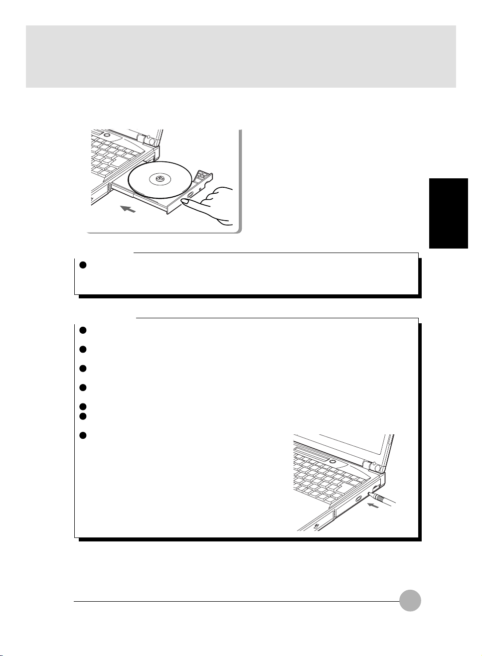
3 Push the tray gently.
IMPORTANT
When you set a CD, align the hole of the CD to the protrusion in the center of the tray and
inset the CD firmly until you can hear a snap sound, or the CD removes from the tray inside of
the drive causing a damage the tray, the inside of the drive and the CD itself.
Critical Point
As the CD drive unit in this PC is electronically locked, you can set/remove a CD only when
the PC unit is working.
The unit may vibrate and cannot work sufficiently if you use a CD with a sticker or any other
medium with wrong centroid.
If you cannot push and close the tray completely, pull the tray out until you can hear snap
sound and then push it again.
The tray may not close when the power of the PC is turned off. In this case, turn on the power
and close the tray.
Follow the same steps to remove a CD.
If you do not install a CD drive unit to the PC unit, enable mute on “Volume control” or other
items for CD in the operating system.
If the tray does not pop out for some reason even though
you push EJECT button, right-click the CD-ROM icon
in the My Computer window and click on Eject.
If the tray does not pop out through the procedure above,
push a hole on the right of EJECT button on the front
side of CD drive unit with a ballpoint pen and pull out
the tray.
SECTION 2
47
Page 59

SECTION 2
6. Floppy Disk Drive
Loading/Ejecting a Floppy Disk
Here is the explanation on how to set/remove a floppy disk.
Loading Insert into the floppy disk drive.
Floppy disk
eject button
Label
Insert a floppy disk with its label to the
topside from the shutter until the floppy
disk eject button pops up.
Critical Point
Use a floppy disk formatted in DOS/
V format. There is no guarantee for
the function of the other type of
floppy disks.
The data on the floppy disk may be
damaged if you remove the disk
while ( ) in the status indicator LCD
appears.
To avoid an intentional erasure of
data on a floppy disk or when you
do not want to write additional data,
slide the write protection tab on the
floppy disk to open up the small hole
(write protection status). If you want
to write data again, slide the write
protection tab to close the small hole.
Ejecting
Floppy disk
eject button
Check that the floppy disk unit’s access
lamp is out, then press the EJECT button.
Write protector
WRITE
ENABLE
WRITE
PROTECT
48
Page 60
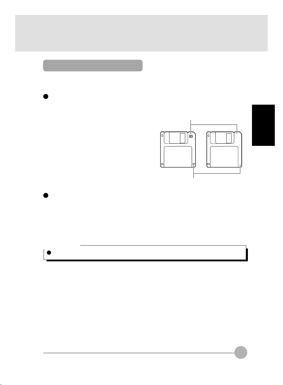
What is a Floppy Disk?
A floppy disk is a medium for storing programs or data. This item explains basic knowledge
and precautions regarding floppy disks.
Types of floppy disks
If floppy disks are classified according to the amount of data they can store (the memory capacity),
typically there are 2 types.
HD mark or no mark
• 2HD floppy disks
These have 1.44MB (megabyte: unit of data
amount) and 1.2MB memory capacities.
• 2DD floppy disks
These have 720KB (kilobyte) memory ca-
pacities, half of the 2HDs.
The differences between the 2 kinds of
floppy disks are shown in the diagram on
the right.
3 mode drive
This computer’s floppy disk drive is a 3 mode drive that can read 1.44MB, 1.2MB and 720KB
memory capacity floppy disks. Therefore it can read nearly all floppy disks. However, when
exchanging data with another computer, you have to be careful if the other computer’s floppy disk
drive is not a 3 mode drive. For example, if the other computer can read 1.2MB floppy disks but
not 1.44MB floppy disks, you have to enter the data after putting it into 1.2MB format in advance
with this computer.
2HD 2DD
Hole or no hole
SECTION 2
Critical Point
Some floppy disks cannot be read by this computer, depending on the floppy disk format.
49
Page 61
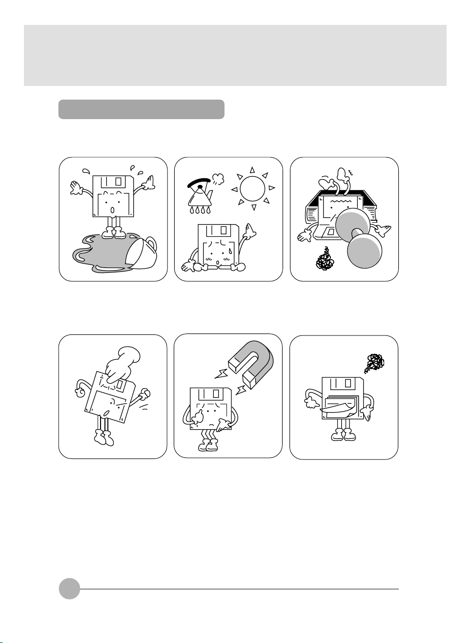
Precautions on Handling
Take the following precautions when using floppy disks in order to avoid damaging them.
Be careful not to spill liquids such
as coffee onto them.
Never touch the surface of the
disk.
Do not place them in places with
high temperatures or in direct
sunlight.
Do not bring them near to
magnetic fields.
Do not bend them or place heavy
objects on top of them.
Do not stick labels on over each
other.
50
Page 62
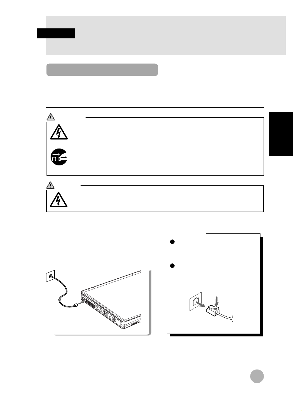
SECTION 2
7. Internal Data Fax Modem
Connection
Some models of this PC series have a built-in V. 90 ready data fax modem and you can enjoy
the error-free communication through MNP Class 4/5 and ITU-T V.42/V42 bis. And in the addition
to this modem function, they have the capability of sending/receiving facsimile.
CAUTION
ELECTRIC SHOCK
Make sure to turn off the power of the PC unit and remove the AC adapter when you
connect a modular cable, or you may experience electric shock.
ELECTRIC SHOCK
When it thunders in the vicinity, turn off the power of the PC unit and remove the AC
adapter and a modular cable.
If you continue using the PC, the thunder may destroy the PC and cause fire.
NOTICE
ELECTRIC SHOCK
Do not insert your finger into the modular connector, or you may experience electric
shock.
SECTION 2
1 Turn off the power of the PC unit and
remove the AC adapter.
2 Connect the modular connector on
the PC unit and telephones line with
a modular cable.
Critical Point
Make sure to hold down the clip
when you remove the plug from the
modular connector, or it may be
damaged.
We recommend using the AC
adapter when you use the modem,
as it consumes a lot of power.
51
Page 63
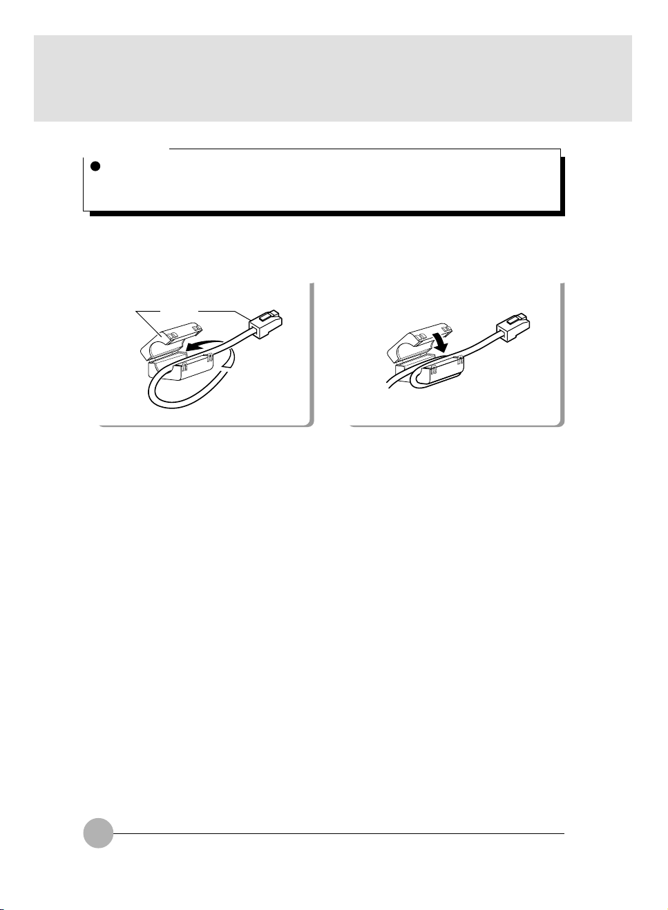
Critical Point
When you connect a data fax modem for the modem-model PC (equipped with a built-in nonfax modem), attach a core onto a modular cable to reduce unnecessary radio wave radiation,
and insert the plug with the core to the PC unit.
1 Round a cable once immediately after the
modular cable plug.
Core Plug
Make sure not to pinch the cable when you
close the core.
2 Close the core.
52
Page 64

SECTION 2
8. Using Internal LAN
Connection
Some types of this PC series have a built-in LAN device to enable high-speed connection to
LAN system through 100BASE-TX and the LAN connection through conventional 10BASE-T
is also available.
CAUTION
ELECTRIC SHOCK
Make sure to turn off the power of the PC unit and remove the AC adapter when you
connect a LAN Cable, or you may experience electric shock.
ELECTRIC SHOCK
When it thunders in the vicinity, turn off the power of the PC unit and remove the AC
adapter and a LAN cable, or the thunder may destroy the PC and cause fire.
NOTICE
ELECTRIC SHOCK
Do not insert your finger into LAN connector, or you may experience electric shock.
1 Turn off the power of the PC unit and
remove the AC adapter .
2 Connect the LAN connector on the
PC unit and the network with a LAN
cable.
SECTION 2
Critical Point
Make sure to hold down the clip
when you remove the plug from the
LAN connector, or it may be
damaged.
We recommend using the AC
adapter when you use LAN, as it
consumes a lot of power.
53
Page 65

SECTION 2
9. Security Panel
A unique feature of your LifeBook Series notebook is the Security Application Panel that allows you
to secure your notebook from unauthorised use. The Security Application Panel also allows you to
launch applications with a touch of a button when your system is on. If the security system is activated,
upon starting your notebook or resuming from suspend mode the security system requires you to
enter a password code using the buttons on the 5-button Security Application Panel. After entering a
correct password, your notebook resumes system operation.
Security Panel Setup
When you receive your LifeBook, the security panel application is preinstalled without any passwords.
The following sections will provide detailed information on your security panel, how to set, change or
remove passwords.
Numbered Buttons
Use these buttons to enter your password.
Refer diagram above.
For E Series
Passwords
The user and supervisor password may be set on this notebook. A supervisor password is typically
the same for all notebooks in a working group, office, or company to allow for system management.
Individual notebooks in a group environment should not use a common password. A password consists of one to five button strokes plus the enter button. A valid stroke consists of pushing one or up
to four buttons simultaneously. The following are valid button strokes:
• Pushing “4” by itself
• Pushing “2” and “3” at the same time
• Pushing “1”, “2”, and “4” at the same time
• Pushing “1”, “2”, “3”, and “4” at the same time
The following are valid passwords input
• “1” + Enter
• “1” + “2” + Enter
• “1” + “2” + “3” + Enter
• “1” + “2” + “3” + “4” + Enter
• (“1” + “2”) +(“1” + “2”+“3”)+(“1” + “2” + “3” + “4”)+“1” + “2” + Enter
54
Page 66

Setting Passwords
When shipped from the factory, no passwords are set. You have a choice of having no password or
setting a supervisor and user password. You must set the supervisor password before the user password.
POINT
The purpose of supervisor password is to be able to bypass the user password in case the user
password is forgotten. The supervisor password alone will not lock the system.
Enter Button
After entering the button strokes, push this button to enter the password into the notebook. Refer
diagram above.
Setting Supervisor Password
You must set a supervisor password prior to setting any user passwords. The supervisor password
can bypass the user password.
1. Go to the Start menu.
2. Click on Run
3. Type in FJSECS.EXE, then press [Enter]
4. Follow the on-screen instructions to set the Supervisor password.
Setting User Password
1. Go to the Start menu.
2. Click on All Programs.
3. Click on Security Panel Application and Set User Password.
4. Follow the on-screen instructions to set the User password.
POINT
You may change or remove the supervisor or user password by repeating the steps defined above.
SECTION 2
55
Page 67

Operate Your LifeBook Security Panel
The security lock feature is in effect both when the system resumes from Off or Suspend state. You
always need to input the user password. Your system would not begin the boot sequence without
entering your supervisor or user password.
From Off State
1. Turn on your system.
2. When lock indicator display on “Status Indicator Panel LCD” lights up, enter the password
and press [Enter]. For example, if the password is 22222, Press Button Number 2 five times
and press [Enter].
3. The notebook will boot to normal operation.
From Suspend State
1. Press your Suspend/Resume button.
2. When lock indicator display on “Status Indicator Panel LCD” lights up, enter the password
and press [Enter].
3. The notebbok should resume normal operation.
Incorrect Password Entry
If an invalid supervisor or user password is entered three times in succession, the system will ‘beep’
for about 1 minute. If a valid password is entered within a minute (while system beeps), the beeping
will stop and the notebook will resume normal operation. If not or invalid password is entered while
the system beeps, the system will return to it’s previous locked state (suspend or off) and the Lock
indicator display on “Status Indicator Panel LCD” will go off. To reactivate the notebook after a password failure, you must press the Suspend/Resume button, then enter a correct password.
Warning
Remember the user password you specified on the Security Panel Application. If you forget the
password you will not be able to use your computer. The supervisor password can override the user
password.
This security function can work only after pushing suspend/resume button. When the system wakes
up by Ring Wake-up, Wake-on-LAN, and Timer Resume function, the security function does not
work.
56
Page 68

System Requirements
Operating System
Microsoft Window 98/ Me, Windows 2000 and Windows XP
Memory
32MB or more
Hard Drive
2MB or more free space
PRECAUTIONS
Opening and Closing Cover
Closing the cover automatically places the notebook into suspend mode. Opening the cover does not
automatically place the notebook into normal operation. Instead, you must enter the proper security
password after pushing the suspend/resume button.
Low Battery Operation
If your notebook has low battery, pushing the suspend/resume button only turns on the lock lamp.
Your notebook does not unlock, the lock lamp turns off after one minute. To resume normal operation,
first attach a power supply to the notebook. Then you may unlock the notebook.
UNINSTALLING THE SECURITY PANEL APPLICATION
You have two options when uninstalling the security panel application:
• Uninstall the security panel application software. This will disable all security feature.
• Uninstall the security panel application with password still active. This will not allow any
changes to the password.
Uninstall The Security Panel Application With Passwords Still Active
Using this feature will not allow any changes to the password.
SECTION 2
POINT
Removing the applications does not remove the password. It simply removes the tool to change/add/
remove passwords. To change your password you must reinstall the application.
User:
1. Go to Start Menu, Click on Control Panel.
2. Open Add/Remove Programs Properties in the Control Panel.
3. Select the Security Panel Application in the list, and click Add/Remove.
4. When the Confirm File Deletion box appears, click Yes.
Supervisor:
1. Go to Start Menu, Click on Control Panel.
2. Open Add/Remove Programs Properties in the Control Panel.
3. Select the Security Panel Application for Supervisor in the list, and click Add/Remove.
4. When the Confirm File Deletion box appears, click Yes.
57
Page 69

Reinstall The Security Application Panel
To reinstall supervisor or user security application. You will need your Drivers and Utilities CD. There
is a folder named Secpanel which contains the setup files for supervisor and user security application.
1. Double-click the setup FJSECS.EXE file. The Installing Security Panel Application window
will appear. Follow the instructions on the screen.
2. Double-click the Setup FJSECU.EXE file. The Installing Security Panel Application window
will appear. Follow the instructions on the screen.
3. Supervisor and user passwords can be set by the Windows Software which are FJSECU.EXE
and FJSECS.EXE respectively. FJSECU.EXE for user password cannot run without supervisor password. First you need to run FJSECS.EXE to set supervisor password before setting
user password. Follow instructions under Settings Passwords.
Warning
The LifeBook Security Panel is designed to prevent theft or unauthorised access to your
LifeBook. It is important that you remember the password that has been set in your LifeBook
otherwise the LifeBook will not be able to operate or resume from suspend.
The LifeBook Security Panel is a high security feature. Should you forget the password that
you have set, you are required to return your LifeBook to :
LifeBook Security Panel Administrator
FUJITSU PC (ASIA) Pte Ltd
238A Thomson Road
#24-01/05
Novena Square Tower A
Singapore 307684
Note: The authorised Fujitsu Service Center will not be able to reset the password. Please
remember to keep your password in a safe place. For reset the security password, there will
be a service charge.
Website: www.fujitsu-pc-asia.com\contactus
58
Page 70

Launching Applications with the Security/Application Panel
The security panel also enables you to launch applications with the touch of a button when your
system is on. Pressing any of the buttons will launch a user-defined application. Your LifeBook is preinstalled with software utilities that let you operate and configure your LifeBook Security /Application
Panel. These utilities are found in two locations. The Disc Player and the Software Instructions (this
document), are found by going to Start -> All Programs -> LifeBook Application Panel. It have CD
Player and Software Instruction. For the Application Panel, go to Start -> Control Panel.
The LifeBook Application Panel makes your LifeBook notebook more than just another notebook computer.
Critical Point
E-mail Notification LED is available on select LifeBook notebook models only.
Configuring your LifeBook Application Panel
When you start Windows, the LifeBook Application Panel is automatically activated.
As an application launcher, the LifeBook Application Panel is very flexible, giving you a variety of
options. To set up the Panel to best suit your needs, we have provided the Application Panel Setup
utility that quickly and easily helps you make the most of this valuable feature.
To configure your LifeBook Application Panel with Application Panel Setup:
1. Click on Start.
2. Click on Control Panel.
3. Click on Application Panel.
SECTION 2
59
Page 71

The Application Panel Setup utility will appear. There are tabs that correspond to the application
buttons on the LifeBook Application Panel. When you receive your notebook, these buttons are
configured to launch specific applications. Below is the example of applications associated with each
button. It may have some different setting on the email launcher button. This setting can be change to
lauch other email client which can access a pop-3 mail server.
Label Button Function Default Application
1 Application A Notepad
2 Application B Calculator
3 Internet Internet Explorer
4 E-Mail Outlook Express
Critical Point
The tabs in Application Panel Setup may not be in the same order as the buttons on your
LifeBook notebook. Please carefully select the tab you wish to change.
To change an application associated with the Application A, Application B, or E-mail buttons, click on
the tab for the button you would like to reconfigure – for example, Application A. Click on Browse from
Start Menu, scroll down the list of applications, click on the application you wish to launch with this
button, and then click OK. The button will now launch the new application.
The Internet tab is different. It comes set to launch your default Windows Internet browser, (Internet
Explorer, unless changed.) In order to reconfigure it to launch another program follow these easy
steps:
1. Click on Other from the Internet browser box.
2. Click on Browse from Start Menu.
3. Scroll down the list of applications, and the click on the application you wish to launch
with this button.
4. Click OK.
60
Page 72

The button will now launch the new application. If you want to return to launching your Windows
default Internet browser with this button, you need only click on “Default Internet Browser” from the
Internet browser box. Be aware that you will erase the settings for the “other application”. If you wish
to go back to launching the “other application” from this button, you will need to reconfigure it as
described above.
When you have finished with Application Panel Setup click on OK, and the new settings will take
effect. You can reconfigure your LifeBook Application Panel as often as you like.
Critical Point
The Internet or E-mail buttons can be configured to launch any application you wish, not just
an Internet browser or e-mail program.
Enabling/disabling Application Launcher button (Select Models Only)
At the bottom of each application setup page are two selectable options. The first will “Keep this
button active even on Standby”, and the second will “Keep this button active even on Hard Drive
Timeout”. You can enable/disable either or both of these functions simply by check or unchecking the
check Box.
Critical Point
If you choose to have the buttons work when the notebook is in standby or pseudo-off, they
will function even if hit accidentally. This will turn on your notebook even if you are not present
or using your notebook. This could deplete your battery, and you will need to recharge it
before using the notebook. As a precaution, move the selector switch, if available, to the
Lock position when you are away from your notebook.
Configure your E-mail Account Settings
Critical Point
The E-mail Notification LED is available on select LifeBook notebook models only.
To use the E-mail LED notification, you must have access to a POP3 Server with no Security
Password Authentication. Contact your service provider to determine if they support POP3
without Security Password Authentication.
The LED light will ligh-up and you can hear a beeping sound when there is a new email in
your mailbox. The LED light will turn off after you have read your mail and close the E-mail
application.
SECTION 2
61
Page 73

To configure the E-mail Account Settings:
1. Click on Start.
2. Click on Control Panel.
3. Click on Application Panel.
4. Click on the E-Mail tab.
5. Click on E-Mail Account Settings...
6. The E-Mail Setup screen appears. Choose the type of connection: LAN or Dial Up.
62
Page 74
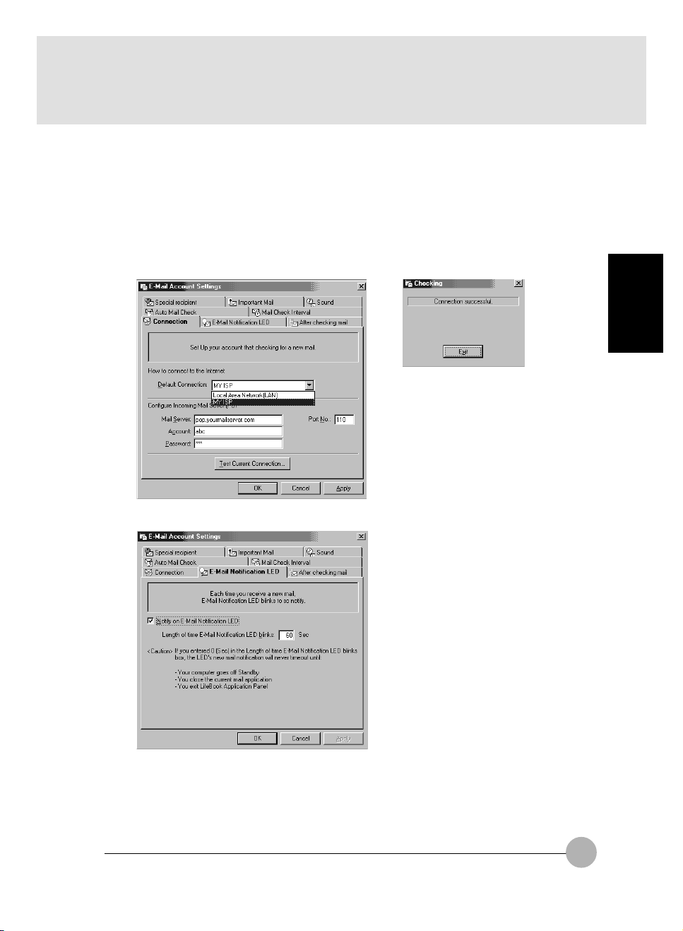
• If LAN: Click on LAN. Enter the POP3 Server name, your account name and password for that
account. Consult your Service provider if you do not know or are unsure of the information
requested.
• If Dial Up: Click on Dial Up. Choose the Dial up configuration (as previously set in Dial Up
Networking) you wish to retrieve mail from. Enter the POP3 Server name, your account name
and password for that account. The account name and password should be the same information
you entered in the Dial Up configuration. After all the information has been entered, test the
connection by clicking on “Testing connection with current setting”. If an error occurs, check
the settings and information on Dial Up Network and E-mail LED notification. If no error found,
it will show connection successful.
To configure E-Mail Notification LED (available on select LifeBook notebook models only)
SECTION 2
You can adjust the LED blinking time.The default is 60 seconds after mail has been retrieved.
After the setup (Dial Up Networking/E-mail/E-mail LED) is completed, you are ready to retrieve mail.
When you press the E-mail button, your system will establish connection with your provider, check for
and retrieve new mails, terminate the connection, and activate the blinking LED to alert you of new
mail. The LED will turn off after you have read you email and close the E-mail application. This only
applicable for model have an email notification LED.
63
Page 75

To configure After checking mail
This setting let you set your computer to return back to the previous power saving state after checking mail.
To configure Auto Mail Check
This function allow you to specify day and time for checking new mail. Only applicable when the PC
stays Standby. If there is a new mail, you will hear a beeping sound.
64
Page 76
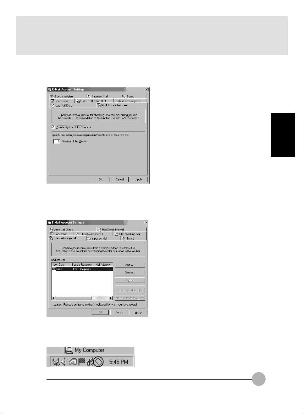
To configure Mail Check Interval
This function allow you to specify an interval (minutes) for checking for a new mail during you use the
computer.Recommendation of this function use with LAN connection.
To configure Special recipient
This function allow you to add a special recipient on the Address List.
You have to specify from the Mail Check Interval to check the check box of Periodically check for New
Mail from the menu Mail Check Interval.
SECTION 2
If there is an email from special recipient that you have set from the Special Recipient menu , it will
show a small icon of the envelope turning around on the taskbar. This will only work when you have
set Mail Check Interval for checking new mail periodically.
65
Page 77
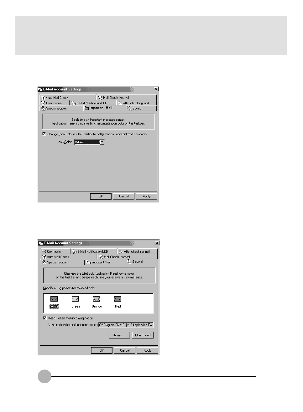
To configure Important Mail
This function allow you to change the icon color on the taskbar to notifies you that an important mail
comes.
To configure Sound
This allow you to change the LifeBook Application icon's color on the taskbar and beeps each time
you receive a new message.
66
Page 78
Using the Disc Player
The Disc Player enables you to use your notebook’s disc drive as an audio Disc Player.
Critical Point
If you shut down from Windows while the Disc Player is playing an audio CD, it will stop. To
continue to use the Disc Player, you have to restart you Windows.
While your Disc Player is playing an audio cd, you put your system into standby Mode or
Hibernate. The Disc player will stop. To continue playing the audio cd, you have to wake-up
the system from standby or hibernate and press the play button.
Because of the Windows CD auto-insertion function, audio CDs will immediately start playing after they are inserted if your notebook is On.
SECTION 2
67
Page 79
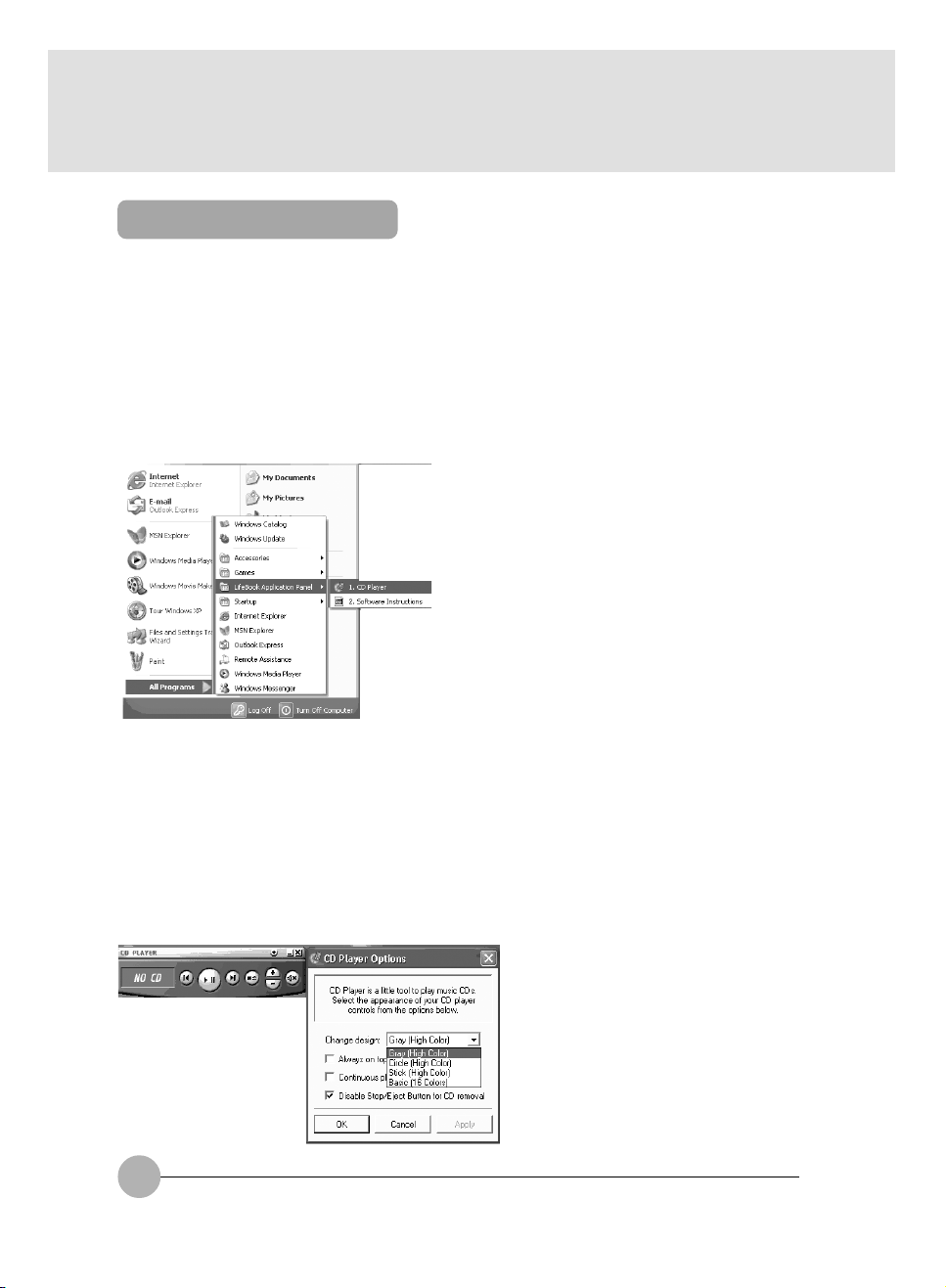
Desktop Control Panel
Your LifeBook notebook includes a CD Player control panel. You may use this panel to operate the
Disc Player.
To use the desktop control panel:
1. Click on Start.
2. Click on All Programs.
3. Click on Lifebook Application Panel.
4. Click on Display CD Player.
The desktop control panel will appear in the upper right corner of your screen.
To close the panel, click on the “x” button. To minimize the panel, click on the “-” button.
You can select from four appearances for your CD Player. Simply double click on the track display
area of the panel and a menu will appear which will allow you to select from a pull down menu. On the
CD Players Options menu box, you have an options to select : Always on top, Continuous play and
Disable Stop/Eject Button from the CD removal. If you click on “Always on top” the desktop controls
will always be seen on your screen, no matter what other application you are running. If you click on
“Continuous Play”, your Disc Player will automatically start over at the beginning as soon as it finishes the last track. By default the Eject Button is disable from the CD Player Options. Once you press
the Eject button from CD Player, the drive will not eject. If you want the Eject Button to be function,
uncheck this options. The CD Player design have a few options for you to change. It consists of Grey
the default CD Player design ,Circle, Stick and Basic. Please refer below for the change of the CD
Player design.
68
Page 80

Grey (High Color)
Circle (High Color)
SECTION 2
Stick (High Color)
You can move the desktop control panel to anywhere on your desktop. Drag it by clicking on the track
number display, holding it down, and dragging the control panel.
When you have placed it where you would like, release the mouse button.
Basic (16 colors)
Critical Point
If you have your display set to 256K colors the basic display will appear no matter which one
you select. You will need to set your display colors to more than 256K in order to select other
display appearances.
When you close the Disc Player’s desktop control panel, it will stop the audio Disc Player.
Precautions
• LifeBook Application Panel uses the date and time settings of your LifeBook notebook. If the date
and time are off, you can adjust this setting in the Windows Control Panel.
• If you insert an audio CD which has both audio and data tracks into the Disc Player, the Disc Player
may fail to play the first audio track.
• The Volume Up, Volume Down and Mute controls for the Disc Player desktop control panel adjusts
the volume of the CD audio line only. It does not adjust your notebook’s master software volume
control or the manual volume on the LifeBook notebook.
• The Disc Player desktop control panel is designed to be displayed in High Color (16-bit) or in True
Color (24-bit or more). If you have your notebook’s display set for 256 colors or less, the Disc
Player control panel will display in a “basic” mode.
69
Page 81

SECTION 2
10.Mouse
Connecting PS/2 Mouse
You can connect a PS/2 standard mouse to the auxiliary keyboard/mouse connector on this
PC.
1 Turn off the power of the PC unit or suspend it.
2 Connect a mouse.
Critical Point
When you connect a PS/2 mouse,
the flat point is automatically
disabled.
If you want to use both of a mouse
and the flat point or if you want to
set the hot plug function, set up them
in “Keyboard/mouse setting” in BIOS
set up.
Connect the mouse to the auxiliary
keyboard/mouse connector on the back of
the PC unit. Make sure that the arrow mark
on the connector is on the topside when you
connect it.
Connecting USB Mouse
Supported only by Windows XP, Windows 2000, Windows 98 and Windows Me
1 Connect a mouse to the USB mouse of this PC.
Critical Point
USB connector
USB connector
You can connect a USB mouse to the USB
connector. Align the connectors and insert it
straight.
You can connect and remove a USB
mouse while the power of the PC is
on. Make sure that you connect the
connector straight.
The flat point is not disabled even
when you connect a USB mouse.
You cannot use a USB mouse in MSDOS mode.
70
Page 82

Disabling Flat Point
When you connect a USB mouse to this PC, both of the flat point and the USB mouse are
enabled. If you want to disable the flat point when you connect a USB mouse, make the following
settings:
1 Set “Internal pointing device” item in BIOS setup to “Manual”
2 When system starts up, push down the [F4] key while pressing down the [Fn] key.
The flat point is enabled or disabled every time when you push down the key.
IMPORTANT
Make sure to connect a mouse when you disable the flat point.
Critical Point
Even though you disabled the flat point by pushing down the F4 key with pressing down the
Fn key, the flat point is enabled after restart or resume operation of the PC.
If you set “Internal pointing device” item in BIOS set up to “Always disabled”, the flat point is
always disabled.
If you set “Internal pointing device” item in BIOS set up to “Always disabled”, the flat point is
always disabled.
SECTION 2
71
Page 83

Using the Mouse
Moving the Mouse.
Place your hand on the mouse so that your fingers are resting on the left and right buttons and
move the mouse by sliding it over your desktop or other smooth surface. The arrow (called the
mouse pointer) on the screen moves in the same way as the mouse. Try moving the mouse while
watching the screen.
Button operations
• Click
Click, click
72
Click
Press the left mouse button once until it clicks.
The action of pressing the right button once firmly
enough that it clicks is called a “right click”.
Press the mouse left button two times quickly in a
row.
Page 84

• Pointing
• Dragging
Press
Align the mouse pointer with a menu item. When
there is another level for the menu item the cursor
is on (when > is displayed at the right of the menu
item), that menu level is displayed.
SECTION 2
Release
Move the mouse pointer with the mouse left button
held down, then release the button at the desired
position.
73
Page 85

SECTION 2
11. Wireless Mouse
This chapter explains fundamentals of handling and operation of the wireless mouse with
matters that require attention. Before using the wireless mouse, carefully read this chapter so
that you’ll have a good knowledge to use this wireless mouse.
Precautions on safety
Strictly observe the following instructions for safe use of the wireless mouse.
Before use, carefully read these safety precautions for using the wireless mouse correctly.
After reading this guide, keep it handy for quick reference.
The following symbol with a word WARNING or CAUTION frequently appears in this chapter. Please
read carefully and understand it.
WARNING
If an external substance (metallic particle, water, etc.) gets into the wireless mouse,
immediately contact the store that you purchased it. Don’t use the mouse with a foreign
substance inside because it may cause breakout of fire or electric shock.
If the wireless mouse falls down or the cover is damaged, contact the store that you
purchased. If such the mouse is continuously used as it is damaged, it may cause breakout
of fire or electric shock.
Don’t use the wireless mouse in a place where flammable gas is generated to prevent
accidental breakout of fire.
Be sure to use the specified batteries only. Use of an unspecified battery may cause
damage to the wireless mouse, breakout of fire or electric shock.
74
Page 86

CAUTION
Don’t leave the wireless mouse in a place where it is directly exposed to the sun or the
temperature is expected to rise extremely, for example, in a car exposed to the scorching
sun, for a long time. Extremely high temperature may cause the cover and other parts of
the wireless mouse to be heated, deformed, melted, or to fire because its inside is heated.
Avoid using the wireless mouse in a dusty or humid place. If the wireless mouse gets dust
or moisture inside, it may cause failure of the mouse or outbreak of fire.
Don’t put the wireless mouse in a place where it is exposed to steam or soot such as in a
kitchen or near a humidifier, because it may cause a fire.
Neither dismantle the wireless mouse nor remove any part from it. If it is done so, it may
cause fire or electric shock.
Don’t cover or wrap the wireless mouse with cloth or other thing. If done so, the mouse
becomes hot because of poor radiation of heat and it may cause deformation of the cover
and breakout of fire. Use the wireless mouse in a well-ventilated condition.
Don’t insert or drop a metallic particle, flammable thing or foreign substance into the
wireless mouse. If there is a foreign substance inside the wireless mouse, it may cause a
fire.
Don’t put the wireless mouse on a slant or unstable plane or in a place where it is easily
affected by strong vibration. If the mouse falls down, it may cause damage to the mouse or
injury to a person.
Don’t give a strong shock or vibration to the wireless mouse, otherwise the mouse may fall
into failure.
Don’t clean the wireless mouse with thinner or benzene, or don’t spray insecticide or the
like to it. Such the chemical may cause the mouse to crack or catch fire.
SECTION 2
75
Page 87

Preparation and Preliminary knowledge
Loading of batteries
Load the wireless mouse with two AAA-size alkaline batteries referring to the article “Replacing
batteries” of this manual.
H-L-OFF switch
Infrared transmission power of this wireless
mouse can be switched between low and high
with the H-L-OFF switch. Set this switch to the
H (High power mode) or L (Low power mode)
position taking the operating environment and
conditions into consideration. When this mouse
is out of use, set this switch to the OFF position
for saving battery power.
Operating method
This wireless mouse transmits data on mouse operation to the personal computer on infrared
rays. When operating the wireless mouse, point its transmitter part at the photosensor of the
personal computer. The operating method of this wireless mouse is the same as the general PS/
2 mouse.
It is recommended to use this wireless mouse within a distance of 1.5 m (High power mode) or
0.5 m (Low power mode) from the personal computer.
Critical Points
The one-touch operation buttons cannot be
used in the following cases.
The illustration of a personal computer
appearing on this page is just a reference.
The outward appearance slightly differs with
the model. Before using this wireless mouse,
check the personal computer for the location
of the photosensor for the wireless mouse.
OFF
L
H
76
Photosensor
for wireless
mouse
Wireless mouse
Page 88

Setup of personal computer and wireless mouse
Setup of personal computer
In the BIOS setup under Keyboard/Mouse features, Infrared Mouse must set to Enable.
Identification of mouse
If multiple wireless mice are used close to each other, it is needed to identify every wireless
mouse with an individual identification code to avoid radio interference. For identify a wireless
mouse, open the lid of the battery chamber on the bottom of the mouse and set an identification
number with the DIP switch (refer to the table below).
For turning on/off each
element of the DIP switch,
use a pointed stick such as
a ball-point pen or the like.
1 2 3
OFF
ID
0 ononon
1 Off on on
3 ononon
4 Off on on
5 ononon
6 Off on on
7 ononon
DIP switch
123
Critical Points
On shipping a wireless mouse from the factory, its identification number is set at “7”.
When the identification number of a wireless mouse is changed, turn off the personal
computer once and again turn it on, or suspend the personal computer and resume it to make
it recognize the new identification number of the mouse.
The personal computer recognizes the identification code of a wireless mouse when it
receives a signal of the identification code for the first time after it is turned on or resumed.
SECTION 2
77
Page 89

Replacing batteries
1 Remove the lid of the battery chamber.
3 Set new batteries in the battery chamber.
Pay heed to the polarities (+ and - poles) of
each battery so as to set it in correct
orientation.
2 Remove the old batteries.
4 Fit the lid of the battery chamber to
the wireless mouse.
CAUTION
Check the orientation (directions of + and - poles) of each battery so that it is correctly set
in the battery chamber.
Don’t use a used battery mixedly with a new battery or two new batteries that are different
in brand or rating from each other.
When the wireless mouse won’t be used for a long time, remove the batteries to prevent it
from trouble such as leak of electrolyte. If electrolyte leaks from the battery, clean the inside
of the battery chamber, particularly metal terminals, and its periphery with soft cloth that is
moistened with water once and then tightly squeezed to remove electrolyte, and carefully
wipe out moisture with dry soft cloth.
When you get electrolyte on your body, carefully wash it out with water. If electrolyte gets
into your eyes or mouth, immediately wash it out with water and consult a doctor as soon as
possible.
Be careful not to make a short-circuit between terminals of the battery chamber.
Don’t put any battery in water or fire. Don’t take any battery apart to pieces.
Don’t charge the battery of this wireless mouse.
Don’t directly solder the battery.
Don’t keep batteries in an extreme temperature condition.
Don’t give a strong shock to batteries.
When disposing used batteries, follow the regulations and directions of the local autonomy
concerned.
78
Page 90
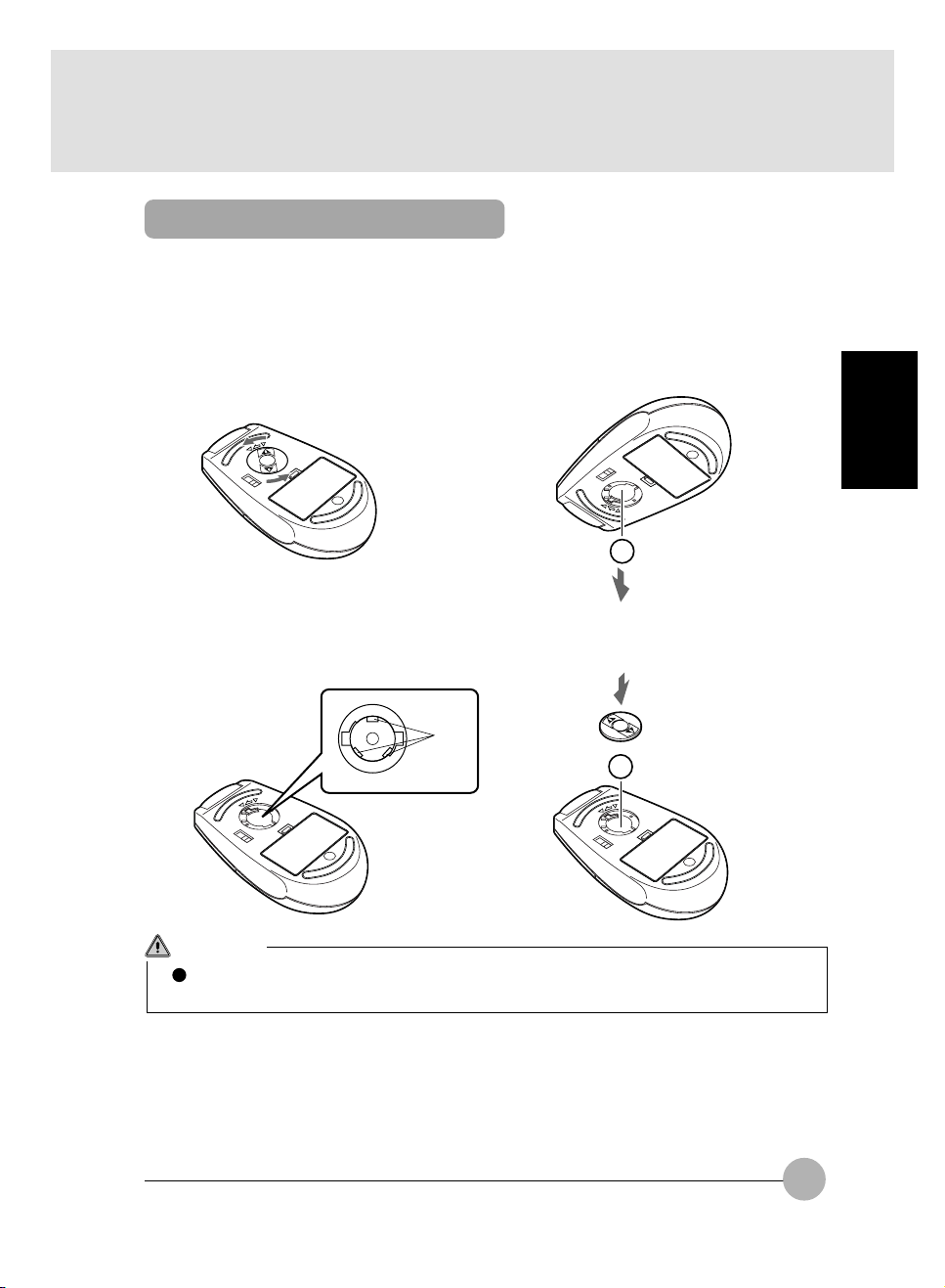
For good maintenance
If the ball or roller of the wireless mouse gets dust or soiled, it may cause malfunction of the mouse.
Be sure to clean the mouse regularly (once a month or so) according to the following procedure.
1 Remove the mouse ball cover.
Turn the mouse ball cover in the
direction of the arrow and remove it.
2 Remove the ball from the mouse.
Lift the mouse with a hand and receive
the ball falling down with the other hand.
Wash the ball with water and dry it up.
SECTION 2
3 Clean the inside of the mouse.
Wipe down the roller, inside of the ball
chamber and cover with dry soft cloth.
Roller
4 Restore the ball and cover to their
original positions.
CAUTION
Don’t leave moisture inside the mouse. Don’t use any organic solvent such as alcohol,
benzene, etc. for cleaning.
79
Page 91

Caution
Don’t use the wireless mouse pointing it at the infrared communication port of the personal
computer to avoid malfunction of the infrared communication port.
If the button of the wireless mouse is held depressed, the battery is depleted in a short time.
Don’t put anything on the mouse and don’t leave the mouse upside down.
Don’t expose the photosensor of the personal computer directly to the sun or a strong light,
otherwise the personal computer may malfunction or communication distance may be
shortened.
Troubleshooting
If the wireless mouse malfunctions, check the following matters. If the trouble still remains in spite of
your check and measure, consult with the store that you purchased the computer/mouse.
Symptom
Inoperative
Radio interference
Abnormal mouse
operation
Check point
Are the batteries set correctly?
Is the mouse pointed at the
photosensor of the personal
computer?
Is there anything obstructive
between the mouse and
photosensor of the personal
computer?
Is the mouse operated in the
receiving range of the
photosensor of the personal
computer?
Are the multiple wireless mice
identified by their individual
identification codes?
The batteries are depleted, aren’t
they?
The ball or roller of the mouse
gets dust or soiled, doesn’t it?
Measures
Set the batteries correctly (in
correct orientation).
Point the transmitter of the mouse
at the photosensor.
Remove the obstruction, if there
is.
Relocate the personal computer
or mouse in the receiving/
transmitting range of the
photosensor/mouse.
Identify the respective mice by
individual identification codes.
Replace the batteries with new
ones.
Clean the inside of the mouse.
80
Page 92
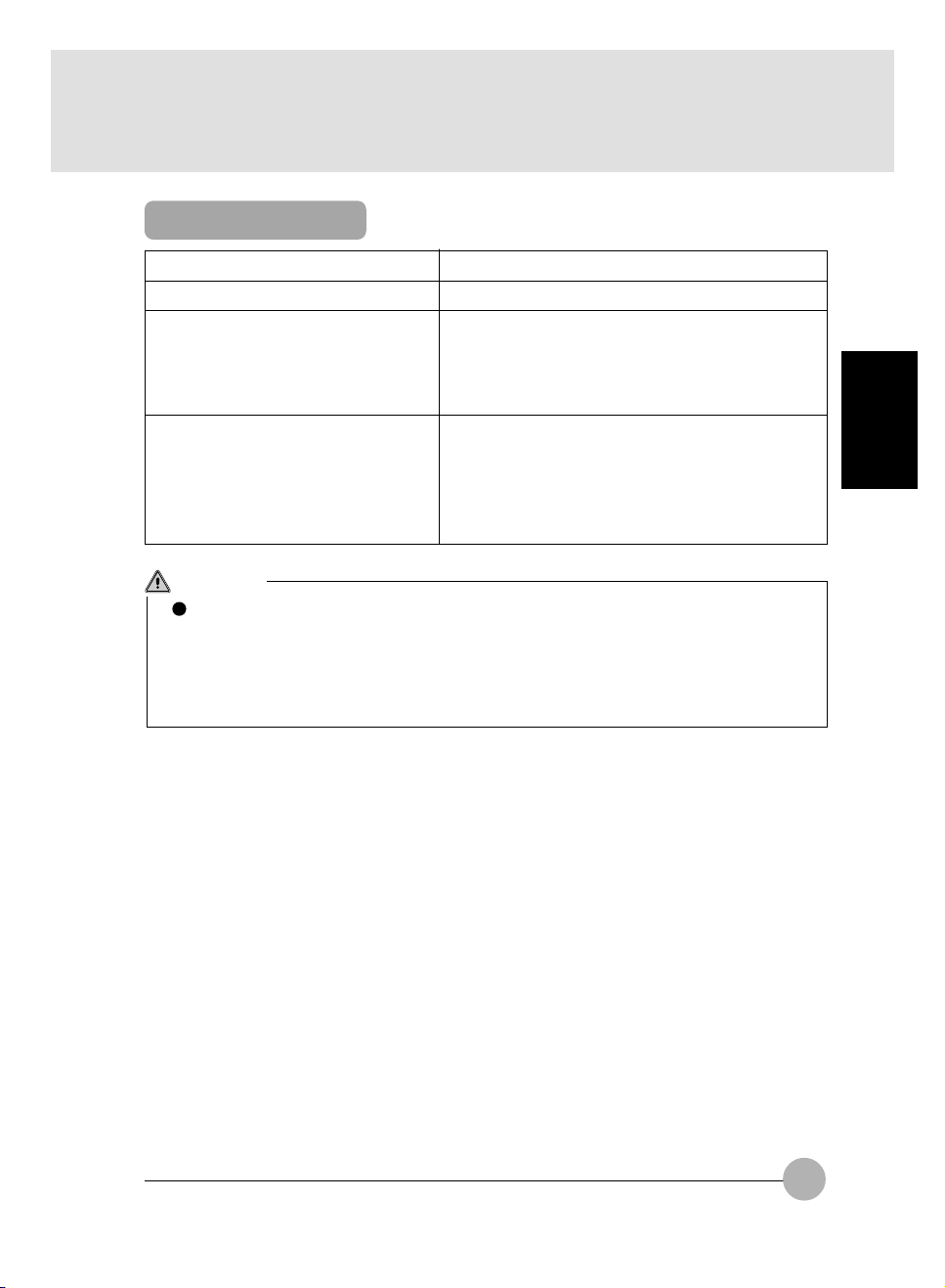
Specifications
Item
Transmission system
Service life of battery
(alkaline battery)
(in Low Power mode)
Operable range
6 months approximately (under operating conditions:
8-hours/day, 5-days/week, net operating rate of mouse
(condition not in use: power off,
temperature 20 degree centigrade)
H: Distance - within 1.5 m, angle - right
L: Distance - within 0.5 m, angle - right and left +45
up 45 degrees , down 15 degrees
Description
Infrared transmission
= 10 %)
and left 0 degree,
Up and down 0 degree
degrees and - 45 degrees ,
CAUTION
This wireless mouse falls under the class B information processor conforming to the VCCI
(Voluntary Control Conference Against Jamming Caused by Information Processor)
standard.
This wireless mouse is designed to be used in the standard home environment, however, if
it is used near a radio or TV set, it may cause radio interference.
Use this wireless mouse correctly following the instructions of this user’s guide.
SECTION 2
81
Page 93

SECTIONSECTION
SECTION
SECTIONSECTION
SECTIONSECTION
SECTION
SECTIONSECTION
33
3
33
33
3
33
SECTION 3
Page 94
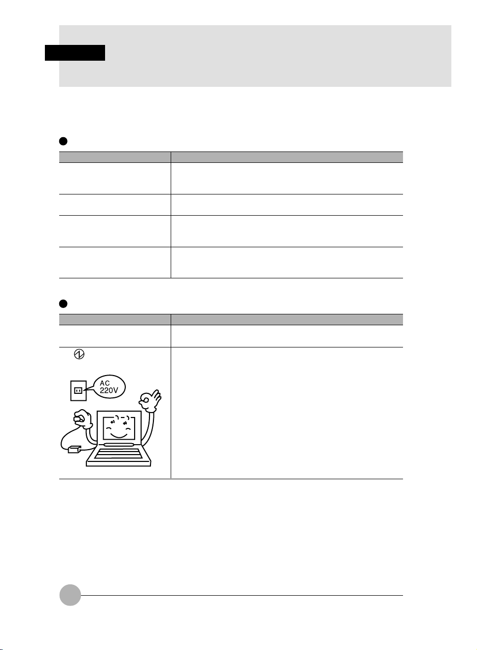
SECTION 4
1. When This Happens
When you are having trouble with this computer, there is something you think is strange, or
there is something you want to do, but do not know how. This section is divided into related
items.
The power does not come on.
Checkpoint
Is the AC adaptor connected?
Is the main switch switched
on?
Is the battery charged?
Has the computer been left
unused for a long time?
Nothing displayed on the LCD panel
Checkpoint
Is anything displayed on the
status indicator LCD?
Is displayed on the LCD
panel?
When using this computer for the first time after purchase, the
battery is not yet charged, so you must connect the AC adaptor
and switch on the main switch.
If the main switch is not switched on, the power will not come on
even if the SUS/RES switch is pressed.
If a beep is heard when the main switch is turned on, then the
battery is running low (LOW BATTERY). Connect the AC
adaptor.
When using the computer for the first time after leaving it unused
for a long time, connect the AC adaptor and switch on the main
switch to switch on the power.
Connect the AC adaptor and switch on the main switch.
• Displayed
Adjust the brightness and darkness with the brightness and
contrast controls.
• Flashing
Press the SUS/RES switch to put the computer into operating
mode.
• When the icon is off on the status indicator LCD.
When the computer runs by the battery power, check the
battery status if it is sufficiently charged for operation or not.
If it is not charged, connect the AC adaptor and charge it.
If you are already using this computer with the AC adaptor
connected, check that it is correctly plugged into the power
socket and into the computer.
Cause and Solution
Cause and Solution
84
Page 95
Checkpoint
Have you been pressing any
of the keys?
Is it set to output to the CRT?
LCD panel hard to read.
Checkpoint
Did you adjust the
brightness?
Battery is not charged.
Checkpoint
Is the AC adaptor connected?
Is the battery overheated
(The on the LCD
display flashes.)?
Is the computer too cold
(The on the LCD
display flashes.)?
Was the charging stopped
midway?
Cause and Solution
On this computer, if the power management functions are set
and no key is pressed for a certain period of time, the CPU stops
and the LCD panel backlight goes out. (In this state, pressing
any key lights up the backlight again.) If the computer stops too
frequently, change the BIOS setup settings.
Switch over to the LCD display with the [Fn] + [F10] keys.
Cause and Solution
Adjust the luminance of the LCD’s backlight with the [Fn] + [F6]
keys or [Fn] + [F7] keys on the keyboard.
Cause and Solution
Check that the AC adaptor is correctly plugged into the power
socket and into the computer.
If the ambient temperature is high and the battery temperature
becomes too high during use, the battery protection function
may be triggered to stop the charging.
If the battery temperature falls too low, the battery protection
function may be triggered to stop the charging.
If you use the computer and disconnect the AC adaptor between
the start of charging and the time the LCD turns off, the
battery will not become fully charged, Once you start charging
do not remove the AC adapter until the LCD turns off.
SECTION 3
The remaining battery charge indicator does not stop flashing.
Checkpoint
Is the battery connected
correctly?
Is the battery low?
Check that the battery is connected correctly. If it is connected
correctly, there is an abnormality in the battery pack, so replace
the battery pack.
Attach the AC adaptor and charge the battery.
Cause and Solution
85
Page 96

Floppy disk can not be used.
Checkpoint
Is the floppy disk loaded into
the floppy disk drive correctly?
Is the floppy disk formatted?
Is the floppy disk unit securely
installed?
Are both items of “Floppy disk
A” and “Floppy controller” of
the BIOS Setup menu set
properly?
Is “Administrator only”
selected for the item “Floppy
disk access” of the BIOS
Setup menu?
Is the floppy disk write
inhibited?
Does it work with a different
floppy disk?
No sound or minimal sound from speaker.
Checkpoint
Is the volume control correctly
adjusted?
Insert the floppy disk with its label facing up, into the drive
shutter and keep inserting firmly until you hear a clicking sound.
New floppy disks can not be used until they are formatted
(initialized). Format the floppy disk.
Firmly install the floppy disk drive unit.
In the case a floppy disk is used, select “1.44/1.2MB 3.5” for the
item “Floppy disk A” and “Use” for the item “Floppy controller”.
In the case a floppy disk is used, select “Accessible at any time”
for this item. When a super disk is used, accessibility cannot be
controlled by this item.
Set the write protect tab on the floppy disk to the write enable
position.
If it works with a different floppy disk then the problem floppy
disk may be damaged.
Turn the volume control to adjust the volume to a proper level. If
volume adjustment with the volume control results in failure,
check to see if the sound driver is correctly installed.
Cause and Solution
Cause and Solution
Can not record from Mic or Line In jack.
Checkpoint
Is the volume adjusted
properly?
LCD panel does not close.
Checkpoint
Is something caught in the
LCD panel?
Turn the volume control to obtain the correct volume. If the line
jack is connected to the sound source, then check that connection. If recording still results in failure after the above-mentioned
operation and check, activate the item “Recording” of the
“Volume Control” and again adjust the volume with it.
Forcing the LCD panel closed can damage it. Check for
something caught in the LCD panel. Also, a metal object such as
a paper clip can cause a breakdown if it gets caught in between
the keys.
86
Cause and Solution
Cause and Solution
Page 97

The power management function is not executed.
Checkpoint
Is Power Savings set to off in
the BIOS setup?
Message displayed on screen.
See the message list.
Data cannot be read from the CD-ROM drive.
Checkpoint
Is the CD-ROM correctly set?
Is there any dirt, condensation
or water on the CD-ROM?
Is the CD-ROM scratched or
extremely warped?
Are you using a non-standard
CD-ROM?
Is the CD-ROM drive unit
securely installed?
The CD cannot be ejected from the CD-ROM.
Checkpoint
Is it in operating mode?
Reset the BIOS setup.
Set the CD-ROM correctly with its label facing upwards.
Wipe it from the center outwards with a dry, soft cloth.
Replace the CD-ROM.
Use a CD-ROM which conforms to the standards.
Securely install the CD-ROM drive unit.
The CD can only be ejected when the personal computer main
unit is in operating mode because its CD- ROM drive has an
electronic lock. Check that the personal computer main unit is in
operating mode and press the EJECT button. If for some reason
the CD tray does not come out even when you press the EJECT
button, insert a clip or something into the hole to the right of the
EJECT button and pull the tray out.
If the tray doesn’t still come out, click the CD-ROM icon in the
“My Computer” window with the right button of the mouse and
then click “EJECT”.
Cause and Solution
Cause and Solution
SECTION 3
Cause and Solution
Super disk cannot be ejected.
Checkpoint
Is the computer in operation?
Cause and Solution
Since the super disk drive secures the super disk by the
electronic lock, the disk can be ejected only when the computer
is in the operation status.
If the super disk cannot be ejected for some reason, insert a thin
linear wire such as a straightened paper clip or the like into the
emergency disk ejecting hole and push it into the depth. The
disk will be resultingly ejected from the drive.
87
Page 98

SECTION 3
2. Care and Maintenance
If you use your Fujitsu LifeBook notebook carefully, you will increase its life and reliability. This section
provides some tips for looking after the notebook and its devices.
Caution:
Electrical equipment may be hazardous if misused. Operations of this product or similar products,
must always be supervised by an adult. Do not allow children access to the interior of any electrical
products and do not permit them to handle any cables.
LIFEBOOK NOTEBOOK
Caring for your LifeBook Notebook
• Your Lifebook notebook is a durable but sensitive electronic device. Treat it with care.
• Make a habit of transporting it in a suitable carrying case.
• Do not attempt to service the computer yourself. Always follow installation instructions closely.
• Keep it away from food and beverages.
• If you accidentally spill liquid on your notebook:
1. Turn it off.
2. Position it so that the liquid can run out.
3. Let it dry out for 24 hours, or longer if needed.
4. If your notebook will not boot after it has dried out, call your support representative.
• Do not use your LifeBook notebook in a wet environment (near a bathtub, swimming pool).
• Always use the AC adapter and batteries that are approved for your notebook.
• Avoid exposure to sand, dust and other environmental hazards.
• Do not expose your LifeBook notebook to direct sunlight for long periods of time as temperatures
above 140°F (60°C) may damage your notebook.
• Keep the covers closed on the connectors and slots when they are not in use.
• Do not put heavy or sharp objects on the computer.
• If you are carrying your LifeBook notebook in a briefcase, or any other carrying case, make sure
that there are no objects in the case pressing on the lid.
• Do not drop your LifeBook notebook.
• Do not touch the screen with any sharp objects.
Cleaning your LifeBook Notebook
• Always disconnect the power plug. (Pull the plug, not the cord.)
• Clean your LifeBook notebook with a damp, lint-free cloth. Do not use abrasives or solvents.
• Use a soft cloth to remove dust from the screen.Never use glass cleaners.
88
Page 99

Storing your LifeBook Notebook
• If storing your notebook for a month or longer, turn your LifeBook notebook off and remove all
Lithium Ion batteries.
• Store your LifeBook notebook and batteries separately. If you store your notebook with a battery
installed, the battery will discharge, and battery life will be reduced. In addition, a faulty battery
might damage your notebook.
• Store your LifeBook notebook in a cool, dry location. Temperatures should remain between 25°C (13°F) and 60°C (140°F).
Travelling with your LifeBook Notebook
• Do not transport your LifeBook notebook while it is turned on.
• Do not check your LifeBook notebook as baggage. Carry it with you.
• Always bring your System Recovery CD that came with your LifeBook notebook when you
travel. If you experience system software problems while travelling you may need it to correct
any problems.
• Never put your LifeBook notebook through a metal detector. Have your notebook hand-inspected
by security personnel. You can, however, put your LifeBook notebook through a properly tuned
X-ray machine. To avoid problems, place your notebook close to the entrance of the machine
and remove it as soon as possible or have your notebook hand-inspected by security personnel.
Security officials may require you to turn your notebook On. Make sure you have a charged
battery on hand.
Outlet type Location
United States, Canada, parts of Latin America, Japan, Korea,
the Philippines, Taiwan
SECTION 3
Russia and the Commonwealth of Independent States (CIS),
most of Europe, parts of Latin America, the Middle East, parts
of Africa, Hong Kong, India, most of South Asia
Mexico, United Kingdom, Ireland, Malaysia, Singapore, parts of
Africa
China, Australia, New Zealand
89
Page 100

• When travelling with the hard drive removed, wrap the drive in a non-conducting materials (cloth
or paper). If you have the drive checked by hand, be ready to install the drive if needed. Never
put your hard drive through a metal detector. Have your hard drive hand-inspected by security
personnel. You can however, put your hard drive through a properly tuned X-ray machine.
• Take the necessary plug adapters if you’re travelling overseas. Check the following diagram to
determine which plug adapter you’ll need or ask your travel agent.
BATTERIES
Caring for your Batteries
• Always handle batteries carefully.
• Do not shor t-circuit the battery terminals (that is, do not touch both terminals with a metal object).
Do not carry lose batteries in a pocket or purse where they may mix with coins, keys, or other
metal objects. Doing so may cause an explosion or fire.
• Do not drop, puncture, disassemble, mutilate or incinerate the battery.
• Recharge batteries only as described in this manual and only in ventilated areas.
• Do not leave batteries in hot locations for more than a day or two. Intense heat can shorten
battery life.
• Do not leave a battery in storage for longer than 6 months without recharging it.
Increasing Battery Life
• Power your LifeBook notebook through the AC or optional auto/airline adapater whenever possible.
• If your LifeBook notebook is running on battery power all day, connect it to the AC adapater
overnight to recharge the battery.
• Keep brightness to the lowest level comfortable.
• Set the power management for maximum battery life.
• Put your LifeBook notebook in Suspend mode when it is turned on and you are not actually
using it.
• Limit your DVD/CD-RW/CD-ROM access.
• Disable the Windows CD automatic insertion function.
• Always use fully charged batteries.
• Eject PCMCIA cards when not in use.
FLOPPY DISKS AND DRIVES
Caring for your Floppy Disks
• Avoid using the floppy disks in damp and dusty locations.
• Never store a floppy disk near a magnet or magnetic field.
• Do not use a pencil or an eraser on a disk or disk label.
• Avoid storing the floppy disks in extremely hot or cold locations, or in locations subject to severe
temperature changes. Store at temperatures between 50°F (10°C) and 125°F (52°C)
• Do not touch the exposed part of the disk behind the metal shutter.
90
 Loading...