

Page 1

COPYRIGHT
Fujitsu PC Corporation has made every effort to
ensure the accuracy and completeness of this document.
However, as ongoing development efforts are continually improving the capabilities of our products, we
cannot guarantee the accuracy of the contents of this
document. We disclaim liability for errors, omissions,
or future changes.
Fujitsu and the Fujitsu logo are registered trademarks
and LifeBook is a trademark of Fujitsu Limited.
Built for Humans and ErgoTrac are trademarks of
Fujitsu PC Corporation.
The following are registered trademarks of
IBM Corporation: IBM, IBM PC AT, IBM PS/2.
The following are registered trademarks of
Microsoft Corporation: MS, MS-DOS, Windows 95,
Windows 98, Windows NT.
PCMCIA is a trademark of the Personal Computer
Memory Card International Association.
Phoenix, Phoenix logo, Power Panel, Card Executive
and NoteDock are registered trademarks of
Phoenix Technologies, Ltd.
Intel and Pentium are registered trademarks and
Celeron is a trademark of Intel Corporation.
PC-Doctor is a trademark of Watergate Software, Inc.
LapLink is a registered trademark of
Traveling Software Inc.
AudioRack is
a registered trademark of
ESS Technology, Inc.
McAfee VirusScan is a registered trademark of NAI.
All other trademarks mentioned herein are the
property of their respective owners.
© Copyright 1999 Fujitsu PC Corporation. All rights
reserved. No part of this publication may be copied,
reproduced, or translated, without prior written
consent of Fujitsu PC Corporation. No part of this
publication may be stored or transmitted in any
electronic form without the written consent of
Fujitsu PC Corporation.
DECLARATION OF CONFORMITY
according to FCC Part 15
Responsible Party Name: Fujitsu PC Corporation
Address: 598 Gibraltar Drive
Milpitas, CA 95035
Telephone: (408) 935-8800
Declares that product: Model: LifeBook E362
LifeBook E360
LifeBook E370
LifeBook E380
Complies with Part 15
of the FCC Rules.
This device complies with Part 15 of the FCC rules.
Operations is subject to the following two conditions:
(1) This device must not be allowed to cause harmful
interference, (2) This device must accept any interference received, including interference that may cause
undesired operation.
David Woo Fujitsu 5/21/99
Page 2

CAUTION
Changes or modification not expressly approved
by Fujitsu PC Corporation could void this user’s
authority to operate the equipment.
Shielded interconnect cables must be employed with
this equipment to ensure compliance with the pertinent RF emission limits governing this device.
Notice to Users of the US Telephone Network
The LifeBook™E Series notebook computers may be
supplied with an internal modem which complies
with Part 68 of the FCC rules. On this notebook is
a label that contains the FCC Registration Number
and the Ringer Equivalence Number (REN) for this
equipment among other information. If requested,
the user must provide their telephone company with
the following information:
1. The telephone number to which the notebook
is connected.
2. The Ringer Equivalence Number (REN) for
this equipment.
3. That the equipment requires a standard modular
jack type USOC RJ-11C which is FCC
Part 68 compliant.
4. The FCC Registration Number.
This equipment is designed to be connected to the
telephone network or premises wiring using a standard
modular jack type USOC RJ-11C which is FCC Part 68
compliant and a line cord between the modem and the
telephone network with a minimum of 26AWG.
The REN is used to determine the number of devices
that you may connect to your telephone line and still
have all of those devices ring when your number is
called. Too many devices on one line may result in
failure to ring in response to an incoming call. In most,
but not all, areas the sum of the RENs of all of the
devices should not exceed five (5.0). To be certain of
the number of devices you may connect to your line,
as determined by the RENs, contact your local
telephone company.
If this equipment causes harm to the telephone network, your telephone company may discontinue your
service temporarily. If possible, they will notify you
in advance. If advance notice is not practical they will
notify you as soon as possible. You will also be advised
of your right to file a complaint with the FCC.
This fax modem also complies with fax branding
requirements per FCC Part 68.
Your telephone company will probably ask you to disconnect this equipment from the telephone network
until the problem is corrected and you are sure that
the equipment is not malfunctioning. This equipment
may not be used on coin service telephones provided
by your telephone company. Connection to party lines
is subject to state tariffs. Contact your state’s public
utility commission, public service commission or
corporation commission for more information.
FCC NOTICES
Notice to Users of Radios and Television
These limits are designed to provide reasonable protection against harmful interference in a residential installation. This equipment generates, uses, and can radiate
radio frequency energy and, if not installed and used
in accordance with the instructions, may cause harmful
interference to radio communications. However, there
is no guarantee that interference will not occur in a
particular installation. If this equipment does cause
harmful interference to radio or television reception,
which can be determined by turning the equipment
off and on, the user is encouraged to try to correct the
interference by one or more of the following measures:
■
Reorient or relocate the receiving antenna.
■
Increase the separation between the equipment
and receiver.
■
Connect the equipment into an outlet that is on
a different circuit than the receiver.
■
Consult the dealer or an experienced radio/TV
technician for help.
Page 3

This equipment includes automatic dialing capability.
When programming and/or making test calls to
emergency numbers:
■
Remain on the line and briefly explain to the
dispatcher the reason for the call.
■
Perform such activities in off-peak hours, such
as early morning or late evening.
FCC rules prohibit the use of non-hearing aid
compatible telephones in the following locations
or applications:
■
All public or semipublic coin-operated or credit
card telephones.
■
Elevators, highways, tunnels (automobile, subway,
railroad or pedestrian) where a person with
impaired hearing might be isolated in an emergency.
■
Places where telephones are specifically installed
to alert emergency authorities such as fire, police
or medical assistance personnel.
■
Hospital rooms, residential health care facilities,
convalescent homes and prisons.
■
Workstations for the hearing impaired.
■
Hotel, motel or apartment lobbies.
■
Stores where telephones are used by patrons
to order merchandise.
■
Public transportation terminals where telephones
are used to call taxis or to reserve lodging or
rental cars.
■
In hotel and motel rooms as at least ten percent
of the rooms must contain hearing aid compatible
telephones or jacks for plug-in hearing aid compatible telephones which will be provided to hearing
impaired customers on request.
DOC (INDUSTRY CANADA) NOTICES
Notice to Users of Radios and Television
This Class B digital apparatus meets all requirements
of the Canadian Interference-Causing Equipment
Regulations.
CET appareil numérique de la class B respecte toutes
les exigence du Réglement sur le matérial brouilleur
du Canada.
Notice to Users of the Canadian
Telephone Network
The Canadian Industry Canada label identifies certified equipment. This certification means that the
equipment meets certain telecommunications network protective, operational and safety requirements.
The Department does not guarantee the equipment
will operate to the user’s satisfaction.
The LifeBook E Series notebook computers are
supplied with an internal modem which complies
with the Industry Canada certification standards for
telecommunication network protection and safety
requirements. Before connecting this equipment to
a telephone line the user should ensure that it is permissible to connect this equipment to the local telecommunication facilities. The user should be aware
that compliance with the certification standards does
not prevent service degradation in some situations.
Repairs to telecommunication equipment should be
made by a Canadian authorized maintenance facility. Any
repairs or alterations not expressly approved by Fujitsu
™
PC Corporation or any equipment failures may give the
telecommunication company cause to request the user to
disconnect the equipment from the telephone line.
The connecting arrangement code for this equipment
is CA11A.
The Load Number is 0.2.
The Load Number assigned to each telephone terminal
device denotes the percentage of the total load to be
connected to a telephone loop or circuit which is used
by the device to prevent overloading. The termination
on a loop may consist of any combination of devices
such that the total of the load numbers of all devices
does not exceed 100.
Page 4

Avis Aux Utilisateurs Du Réseau
Téléphonique Canadien
L’étiquette canadienne Industrie Canada identifie
l’équipement certifié. Cette certification signifie
que l’équipement satisfait certaines normes de
protection, d’exploitation et de sécurité des réseaux
de télécommunications. Le département ne garantit
pas le fonctionnement de l’équipement à la
satisfaction de l’utilisateur.
La série LifeBookTME possède un modem
interne conforme aux normes de certification
d’Industrie Canada pour protéger les réseaux
de télécommunications et satisfaire aux normes
de sécurité. Avant de connecter cet équipement à une
ligne téléphonique, l’utilisateur doit vérifier s’il est
permis de connecter cet équipement aux installations
de télécommunications locales. L’utilisateur est averti
que même la conformité aux normes de certification
ne peut dans certains cas empêcher la dégradation
du service.
Les réparations de l’équipement de télécommunications
doivent être effectuées par un service de maintenance
agréé au Canada. Toute réparation ou modification, qui
n’est pas expressément approuvée par Fujitsu PC Corp.,
CAUT ION
For safety, users should ensure that the
electrical ground of the power utility, the
telephone lines and the metallic water
pipes are connected together. Users should
NOT attempt to make such connections
themselves but should contact the
appropriate electric inspection authority
or electrician. This may be particularly
important in rural areas.
ou toute défaillance de l’équipement peut entraîner
la compagnie de télécommunications à exiger que
l’utilisateur déconnecte l’équipement de la ligne
téléphonique.
Le code d’arrangement de connexion de cet
équipement est CA11A.
Le numéro de charge est 0.2.
Le numéro de charge assigné à chaque terminal
téléphonique indique le pourcentage de la charge
totale pouvant être connecté à une boucle ou à un
circuit téléphonique, utilisé par ce périphérique afin de
prévenir toute surcharge. La terminaison d’une boucle
peut être constituée de n’importe quelle combinaison
de périphériques de sorte que le total de numéros de
charge de tous les périphériques n’excède pas 100.
Page 5

UL NOTICE (FOR AUTHORIZED REPAIR TECHNICIANS ONLY)
CAUTION: For continued protection against risk of fire, replace only
with the same type and rating fuse.
CAUTION: Danger of explosion if CMOS battery is incorrectly
replaced. Replace only with the same or equivalent type recommended
by the manufacturer. Dispose of used batteries according to the
manufacturer’s instruction.
WARNING: CMOS and NiCAD batteries may explode if mistreated.
Do not recharge, disassemble or dispose of in fire.
A VERTISSEMENT
Pour assurer la sécurité, les utilisateurs
doivent vérifier que la prise de terre du
service d’électricité, les lignes télphoniques
et les conduites d’eau métalliques sont
connectées ensemble. Les utilisateurs NE
doivent PAS tenter d’établir ces connexions
eux-mêmes, mais doivent contacter
les services d’inspection d’installations
électriques appropriés ou un électricien.
Ceci peut être particulièrement important
en régions rurales.
Page 6

Table of Contents
Page 7

T able of Contents
ii
PREFACE . . . . . . . . . . . . . . . . . . v
SECTION ONE
SETTING UP YOUR LIFEBOOK
E SERIES FROM FUJITSU
Unpacking. . . . . . . . . . . . . . . . . . . . 2
Overview of LifeBook E Series Features . . . . 4
Component Identification . . . . . . . . . . . 6
Top and Front Components . . . . . . . . . . 7
Left-side Panel Components . . . . . . . . . . 8
Right-side Panel Components . . . . . . . . . 9
Rear Panel Components. . . . . . . . . . . . 10
Bottom Components . . . . . . . . . . . . . 11
SECTION TWO
STARTING YOUR LIFEBOOK E SERIES
FROM FUJITSU
Power Sources . . . . . . . . . . . . . . . . . 14
Display Panel . . . . . . . . . . . . . . . . . 15
Adjusting the Keyboard Angle . . . . . . . . 15
Starting Your Notebook for the First Time. . 16
Registering Your LifeBook . . . . . . . . . . 20
Learning About Your Operating System
and Application Software. . . . . . . . . . 21
Power Off . . . . . . . . . . . . . . . . . . . 21
Restarting Your Notebook. . . . . . . . . . . 22
SECTION THREE
USING YOUR LIFEBOOK E SERIES
FROM FUJITSU
Status Indicator Panel . . . . . . . . . . . . . 24
Integrated Pointing Devices. . . . . . . . . . 28
Using the Keyboard . . . . . . . . . . . . . . 32
Volume Control . . . . . . . . . . . . . . . . 34
Batteries . . . . . . . . . . . . . . . . . . . . 34
Floppy Disk Drive . . . . . . . . . . . . . . . 38
SuperDisk 120 Drive . . . . . . . . . . . . . 40
CD-ROM Drive . . . . . . . . . . . . . . . . 40
DVD Drive. . . . . . . . . . . . . . . . . . . 40
Hard Drive. . . . . . . . . . . . . . . . . . . 42
Internal Modem . . . . . . . . . . . . . . . . 43
Internal LAN. . . . . . . . . . . . . . . . . . 43
Infrared Port. . . . . . . . . . . . . . . . . . 44
Power Management . . . . . . . . . . . . . . 44
Pre-installed Software . . . . . . . . . . . . . 49
Data Security . . . . . . . . . . . . . . . . . 60
Boot Sequence . . . . . . . . . . . . . . . . . 61
Identifying The Drivers . . . . . . . . . . . . 62
BIOS Setup Utility. . . . . . . . . . . . . . . 62
Your Save-To-Disk File Allocation . . . . . . 63
SECTION FOUR
USER INSTALLABLE FEATURES
Multi-function Bay Devices. . . . . . . . . . 69
PC Cards . . . . . . . . . . . . . . . . . . . . 75
Parallel Port Devices. . . . . . . . . . . . . . 77
Serial Port Devices. . . . . . . . . . . . . . . 77
USB Devices . . . . . . . . . . . . . . . . . . 77
Microphone . . . . . . . . . . . . . . . . . . 78
Stereo Line In Devices. . . . . . . . . . . . . 78
Headphones . . . . . . . . . . . . . . . . . . 78
Telephone Lines . . . . . . . . . . . . . . . . 78
Page 8

T able of Contents
LifeBook E Series from Fujitsu
iii
Mouse, Keyboard or Keypad . . . . . . . . . 79
External Monitor . . . . . . . . . . . . . . . 79
Theft Prevention Lock. . . . . . . . . . . . . 79
External Installation of the Modular
Floppy Disk Drive . . . . . . . . . . . . . 79
Memory Upgrade Module . . . . . . . . . . 80
LANdock. . . . . . . . . . . . . . . . . . . . 84
Port Replicator. . . . . . . . . . . . . . . . . 87
SECTION FIVE
TROUBLESHOOTING
Identifying the Problem. . . . . . . . . . . . 90
Specific Problems . . . . . . . . . . . . . . . 91
Power On Self Test Messages . . . . . . . . 110
Emergency DVD/CD-ROM Tray Release . . 113
Modem Setup and Commands . . . . . . . 113
Recovery CD-ROM . . . . . . . . . . . . . 114
SECTION SIX
CARE AND MAINTENANCE
Caring for Your Notebook . . . . . . . . . . 118
Increasing Battery Life . . . . . . . . . . . . 119
Caring for Your Batteries . . . . . . . . . . 119
APPENDICES
SPECIFICATIONS & GLOSSARY
Warranty . . . . . . . . . . . . . . . . . . . 122
LifeBook E Series General Specifications . . 122
Pre-configured models. . . . . . . . . . . . 125
Glossary. . . . . . . . . . . . . . . . . . . . 126
INDEX
Index . . . . . . . . . . . . . . . . . . . . . 133
Page 9

LifeBook E Series from Fujitsu
Preface
Page 10

Preface
vi
PREFACE
The LifeBook E Series from Fujitsu PC
Corporation is a powerful notebook computer. It
is powered by an Intel® Pentium® II or Celeron™
microprocessor, has a built-in color display, a vast
array of possible configurations and brings the
computing power of desktop personal computers
(PCs) to a portable environment.
This manual explains how to operate your
LifeBook E Series’ hardware and built-in
system software. The LifeBook E Series
is compatible with the IBM® PC AT.
It comes with Windows 98 Second Edition,
or Windows NT 4.0 pre-installed.
A LifeBook E Series is a completely selfcontained unit with an active-matrix (TFT)
color LCD display. It has a powerful interface
that enables it to support a variety of optional
features. (Figure P-1.)
CONVENTIONS USED IN THE GUIDE
Messages displayed by the LifeBook E Series
appear in Courier type.
Example: Shutdown the computer?
Keyboard keys are shown in boldface
Helvetica type.
Example: Fn, F1, Esc, and Ctrl.
Pages with additional information about a specific topic are cross-referenced within the text.
Example: (See page xx.)
POINT
The point icon highlights information
that will enhance your understanding of
the subject material.
CAUTION
The caution icon highlights information
that is important to your safety, to the
safe operation of your computer, or to
the integrity of your files. Please read all
caution information carefully.
Page 11
Preface
LifeBook E Series from Fujitsu
LifeBook E Series from Fujitsu
vii
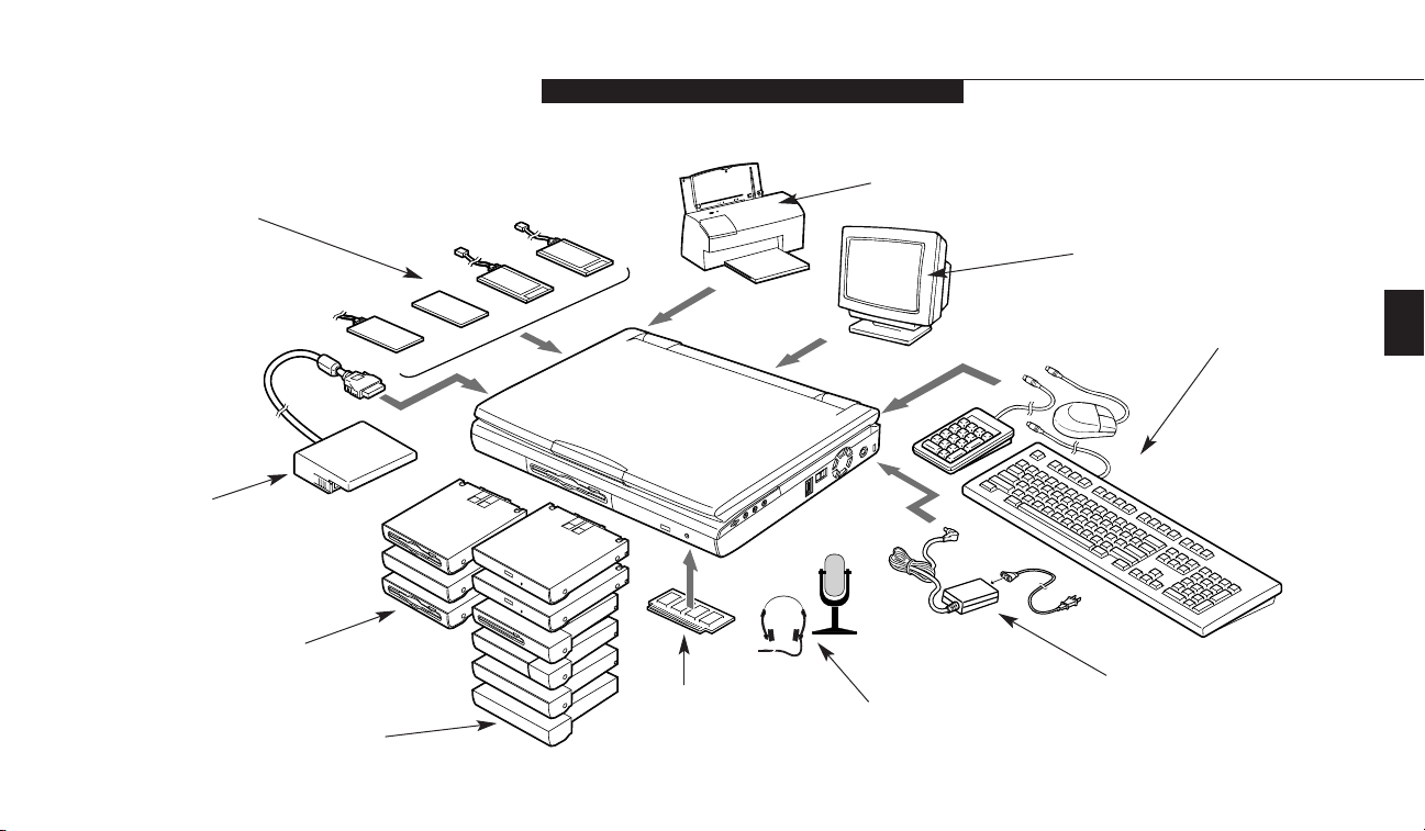
Figure P-1 LifeBook E Series with Both Fujitsu
and Third Party Options
FDD Adapter
PCMCIA Card
Printer
External Monitor
External Keyboard, Mouse,
or Numeric Keypad
Power Adapter
Headphone and Mic
RAM
Bay 1 Devices
Bay 2 Devices
Page 12

Setting Up Your LifeBook E Series
Section One
Unpacking . . . . . . . . . . . . . . . . . . . 2
Overview of LifeBook E Series Features . . . . 4
Component Identification . . . . . . . . . . . 6
Top and Front Components . . . . . . . . . . 7
Left-side Panel Components . . . . . . . . . . 8
Right-side Panel Components . . . . . . . . . 9
Rear Panel Components . . . . . . . . . . . 10
Bottom Components . . . . . . . . . . . . . 11
Page 13
Section One
2
SECTION ONE
SETTING UP YOUR LIFEBOOK
E SERIES FROM FUJITSU
This section describes how to set up your
LifeBook E Series from Fujitsu. We strongly
recommend that you read it before using your
notebook – even if you are already familiar with
notebook computers.
UNPACKING
When you receive your notebook, unpack it
carefully, and compare the parts you have
received with the items listed below and with
your packing label.
You will have some or all of the following.
Please check your packing sheet or the
appendix for your model.
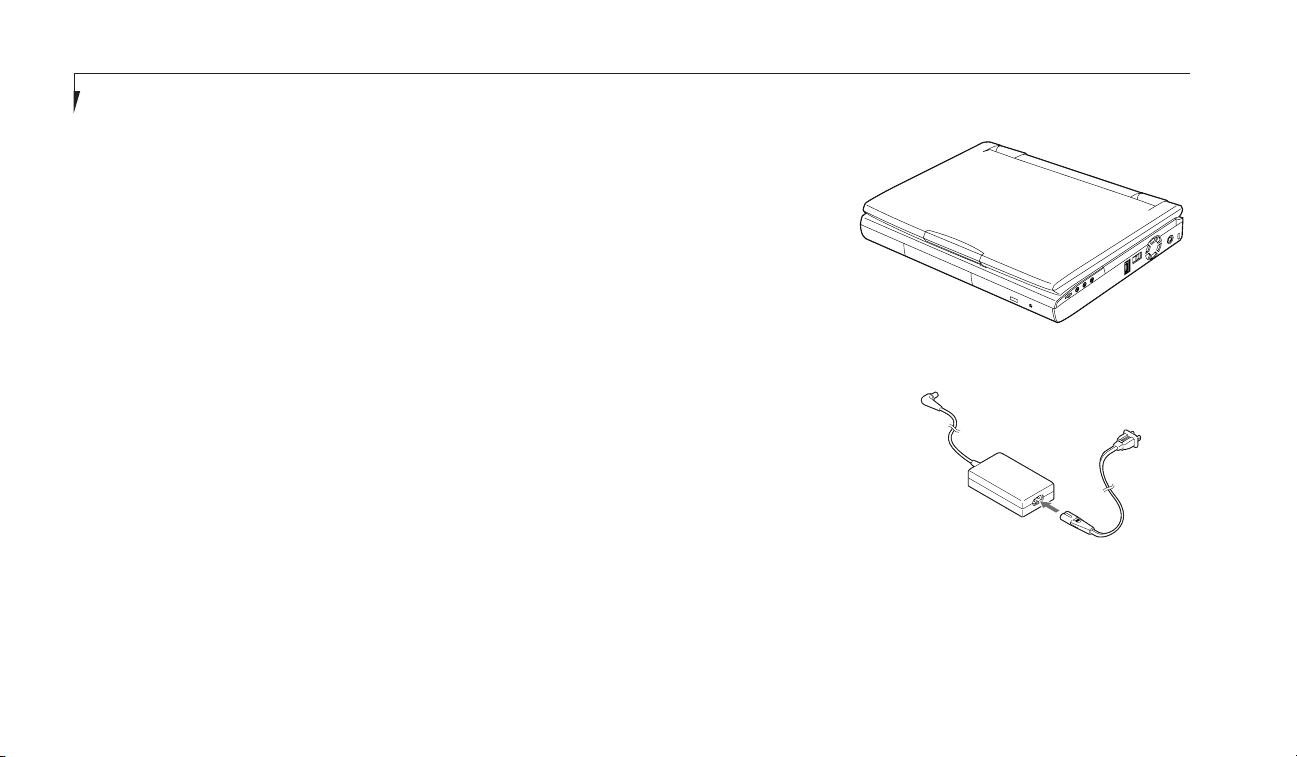
■
LifeBook E Series from Fujitsu.
(Figure 1-1.)
■
AC adapter with AC power cord (located in
the accessories box). (Figure 1-2.)
■
Modular Lithium ion battery. (Already
installed in Multi-function Bay 1 of
your notebook.)
■
Modular 24x maximum CD-ROM drive.
(Already installed in Multi-function Bay 2
of your notebook.)
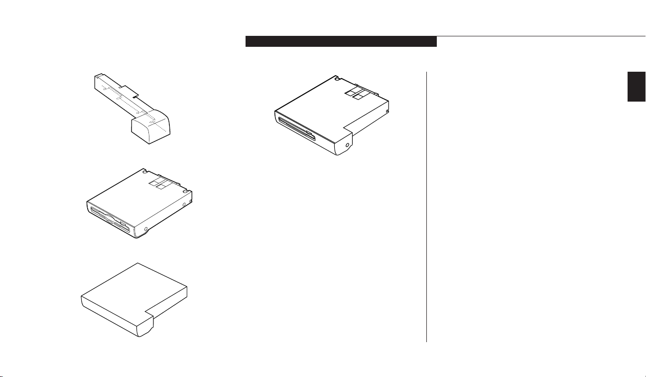
■
Battery adapter for Multi-function Bay 2
(located in the accessories box.) (Figure 1-3.)
■
Modular 3.5" floppy disk drive (located in the
accessories box). (Figure 1-4.)
■
Modular Zip drive (located in the accessories
box). (Figure 1-6.) (Available on some configu-
rations, see appendices for details.)
■
Weight Saver for Multi-function Bay 2
(located in the accessories box.)(Figure 1-5.)
■
Modem (RJ-11) cable (located in the
accessories box).
■
Getting Started Guide and User’s Guide.
■
Microsoft Windows 98 SE or
Windows NT 4.0 Manual.
Figure 1-1 LifeBook E Series Notebook
Figure 1-2 AC Adapter Unit
■
Registration card and customer
information pack.
■
Recovery CD-ROM
(located in the accessories box).
Page 14
One
Setting Up Your LifeBook E Series
LifeBook E Series from Fujitsu
3
Please take a moment now to locate your packing sheet and circle or enter the options that
apply to your LifeBook specifications in the
space to the right.
Once you have checked and confirmed that
your notebook system is complete, read
through the component identification section
and learn about the features of your LifeBook.
Figure 1-3 Battery Adapter for Multi-function Bay 2
Figure 1-4 Floppy Disk Drive
Figure 1-5 Weight Saver (for Multi-function Bay 2 only)
Please take a moment and complete this, for
your future reference.
Date Purchased: ________________________
CPU:@400Mhz Celeron @400Mhz PII
@
333Mhz PII@366Mhz PII
LCD:@XGA (1024x768)@SVGA (800x600)
SDRAM:@32MB@64MB
HDD:@4.3GB@6.4GB@10GB
Communications Port:@V.90 Modem
@
Fast Ethernet Module @None
Multi-function Bay Devices:
@
Floppy Disk Drive FPCFDD05
@
CD-ROM Drive FPCCD09
@
Iomega Zip 100 Drive FPCZIP03
@
Lithium ion Battery FPCBP14
@
Weight Saver FPCBB01
@
Floppy Disk Drive FPCFDA03
Integrated Pointing Devices:
@
ErgoTrac
™
@
Touchpad
Figure 1-6 Modular Zip Drive (Available on
some configurations)
Page 15

Section One
4
CAUTION
The internal modem is designed to the
ITU-T V.90 standard. Its maximum speed
of 53000bps is the highest allowed by
the FCC, and its actual connection rate
depends on the line conditions. The
maximum speed is 33600bps at upload.
OVERVIEW OF LIFEBOOK E SERIES
FEATURES AND OPTIONS
The LifeBook E Series is a compact, yet powerful
notebook computer available with a variety of
features. Please refer to your packing sheet or
the appendix to see which of the following are
included in your configuration.
Features include:
■
Latest high-speed Intel processors.
■
64MB SDRAM on-board expandable to
192MB via expansion slot or 32MB SDRAM
on-board expandable to 160MB via
expansion slot.
■
On-die L2 cache
■
13.1" XGA with active-matrix (TFT) color
display with 1024 x 768 resolution or 12.1"
SVGA with active-matrix (TFT) color
display with 800 x 600 resolution.
■
External monitor support with maximum
1280 x 1024 resolution.
■
2MB embedded SDRAM video memory.
■
wfm/DMI 2.0 compliant.
■
Built-in 10GB, 6.4GB or 4.3GB hard drive.
■
Floppy Disk Drive Adapter to connect
modular floppys disk drive externally.
■
Multi-function Bays which support
the following optional features:
■
Lithium ion battery
(one pre-installed in Bay 1, can be used
in Bay 2 with Battery Adapter).
■
3.5" floppy disk drive (Bay 1 only).
■
24x max CD-ROM drive (Bay 2 only).
■
SuperDisk™ 120 (Bay 1 only).
■
2x DVD-ROM drive (Bay 2 only).
■
Second hard drive (Bay 2 only).
■
Iomega Zip 100 drive (Bay 2 only).
■
Second Lithium ion battery
(Bay 1 and Bay 2 with adapter).
■
Weight Saver (Bay 2 only).
■
Internal V.90 56K fax/data/voice modem.
■
Internal LAN.
CAUTION
The internal modem is not intended for
use with Digital PBX systems. Do not
connect the internal modem to a digital
PBX as it may cause serious damage to
the internal modem or your entire notebook. Consult your PBX manufacturer’s
documentation for details. Some hotels
have Digital PBX systems. Be sure to find
out BEFORE you connect your modem.
Page 16

One
Setting Up Your LifeBook E Series
LifeBook E Series from Fujitsu
5
■
Fast IrDA (4Mbps) compatible infrared port
for wireless data transfer.
(Windows 98 SE only.)
■
Integrated ErgoTrac™ or Touchpad pointing
device for customized comfort and cursor
control. (Custom configured systems only.)
■
External monitor support with simultaneous
display capabilities.
■
Full-size keyboard with three dedicated
Windows keys.
■
Hot swap PS/2 port for an external keyboard
or external mouse.
■
USB device support. (Windows 98 SE only.)
■
Bridge battery for warm-swapping of batteries.
■
Standard pre-installed software:
■
Microsoft Windows 98 SE or Windows NT
4.0 operating system.
■
LapLink Professional for file transfer via
modem, cable or infrared port.
(Windows 98 SE only.)
■
PMSet 98 (Windows 98 SE) or PowerPanel
(Windows NT 4.0) for system
power management.
CAUTION
The internal modems on all Fujitsu E
Series notebooks from Fujitsu PC
Corporation are not qualified for use with
telephone systems outside the United
States and Canada and may not operate
in other countries.
■
Agate Tioman HotSwap for hot-swapping
functionality in Multi-function bays.
(Windows 98 SE only).
■
Phoenix NoteDock for hot docking/
undocking support and hot-swapping
functionality in the Multi-function bays
(with Windows NT 4.0 only).
■
Phoenix Card Executive for PCMCIA card
support. (Windows NT 4.0 only.)
■
PC-Doctor for system diagnostics.
■
McAfee VirusScan for virus protection.
■
ESS AudioRack for 3D-Stereo, audio CD and
other audio controls. (Windows 98 SE only.)
■
Netscape Communicator.
■
Standard user-install software:
■
AOL (Windows 98 SE only).
■
Compuserve (Windows 98 SE only).
■
Earthlink (Windows 98 SE only).
■
Full audio and video features:
■
16-bit SoundBlaster Pro-compatible
sound chip.
■
3D-Stereo for multiple speaker effect.
■
Zoomed Video support for full motion
video acceleration.
(With Windows 98 SE only.)
■
Built-in stereo speakers.
■
Built-in mono microphone.
■
Stereo line in jack.
■
Stereo headphone jack.
■
Microphone jack.
■
Combination PC Card slot accommodates
two Type II or one Type III.
Page 17
Section One
6
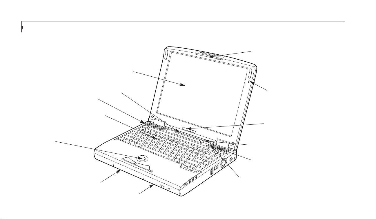
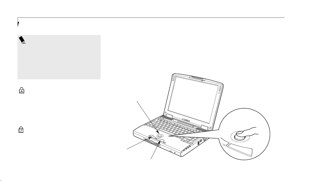
Figure 1-7 LifeBook E Series with Display Open (out of box configuration)
Display Panel
Status Indicator Panel
Keyboard
ErgoTrac™ or Touchpad pointing device
Lithium ion Battery
CD-ROM
Suspend/Resume Button
Built-in Microphone
Brightness Control
Display Panel Latch
COMPONENT IDENTIFICATION
For detailed specifications on each model refer
to Appendices on pages 121–125.
Closed Cover Switch
Stereo Speaker
Stereo Speaker
Page 18

One
Setting Up Your LifeBook E Series
LifeBook E Series from Fujitsu
7
TOP AND FRONT COMPONENTS
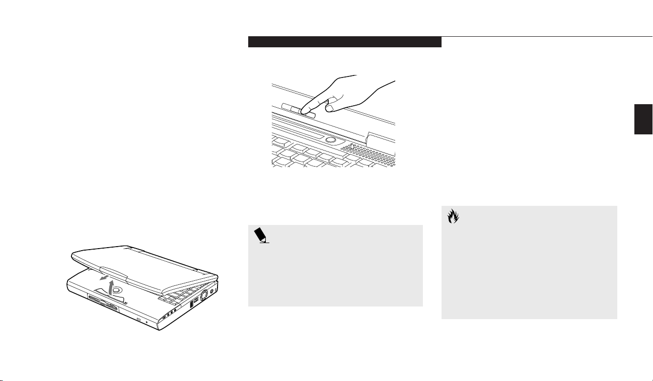
Display Panel Latch
This latch locks and releases the display panel.
When the display panel is released it pops up
slightly to make it easier to open. (Figure 1-7.)
Display Panel
This is a color LCD panel with back lighting for
the display of text and graphics. (Figure 1-7.)
Brightness Control
The brightness control adjusts the overall
intensity of the display panel back lighting.
(Figure 1-7.)
Built-in Microphone
The built-in microphone allows mono audio
input to your notebook. (Figure 1-7.)
Status Indicator Panel
An LCD display of the status of the power state
and source, Suspend mode, battery charge (battery in either Multi-function Bays), floppy disk
drive activity, hard drive or zip drive activity,
CD-ROM drive activity, PC Card activity,
CapsLock, NumLk and ScrLk. (Figure 1-7.)
Stereo Speakers
The built-in dual speakers output stereo sound
from the notebook. (Figure 1-7)
Suspend/Resume Button
The Suspend/Resume button allows you to suspend notebook activity without turning off the
notebook power, and to return it to an active
state. This feature saves power, and is particularly useful when the notebook is running only
on battery power. (See pages 44-49 for more
information on power management.)
(Figure 1-7.)
Closed Cover Switch
The closed cover switch turns off the LCD back
lighting when the display panel is closed, thus
saving power. This switch also behaves as a
Suspend/Resume button, when the closed
cover switch is set to Suspend/Resume in the
BIOS Setup Utility. (see pages 62-63 for more
information on the BIOS Setup Utility)
(Figure 1-7.)
Keyboard
A full-size keyboard with dedicated Windows
keys for input into the notebook.
(Figure 1-7.)
Pointing Device
The pointing device is a mouse-like cursor
control system with two click buttons.
(Figure 1-7.)
CAUTION
Be sure you know which settings are
active for your Suspend/Resume button
before you use it. Misuse can result in
data loss. (See the Power Savings Menu
in the BIOS Guide, see page 63 for more
information.)
Page 19
Section One
8
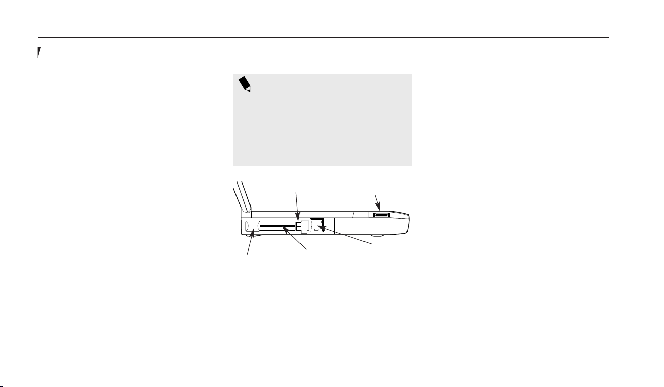
LEFT-SIDE PANEL COMPONENTS
PC Card Slot
The PC Card Slot allows you to install two Type
I or Type II PC Cards or one Type III PC Card.
(See pages 75-77 for more information on PC
Cards.) The button to the left of the card slot
locks the card(s) in place, and the buttons
to the right of the slot eject the card(s) from
the slot. (Figure 1-8.)
Communications Port
The communications port may be configured
with either a Modem (RJ-11) telephone jack for
an internal 56K modem or an Internal LAN
(RJ-45) jack for an internal Fast Ethernet
(10/100 Base-T/Tx) port. Check your packing
sheet or the appendix to see which option (if
any) you have on your LifeBook. (Figure 1-8.)
External Floppy Disk Drive Port
A port for attaching an optional external floppy
disk drive with adapter. This allows you to connect an optional floppy disk drive when the
Multi-function bays are being used for other
purposes. (Figure 1-8.)
Multi-function Bay One
This bay accommodates the following devices:
■
Lithium ion battery. (Pre-installed)
■
SuperDisk 120.
■
3.5" floppy disk drive.
Multi-function Bay Two
This bay accommodates the following devices:
■
24x maximum CD-ROM drive. (Pre-installed)
■
2x maximum DVD-ROM drive.
■
Lithium ion battery mounted with the
Battery adapter for Multi-function Bay 2
(a second battery can be purchased separately for a dual battery configuration).
■
6.4 GB Second hard drive.
■
Iomega Zip 100 Drive (standard with E370
and E380).
■
Weight Saver.
Figure 1-8 LifeBook E Series Left-side Panel
PC Card Eject Buttons
Communications port
PC Card Slots
PC Card Lock
External FDD
connector
POINT
The Weight Saver option for Multi-function Bay 2 is meant to fill the bay when
no other device is installed. It is not
recommended that you use your
LifeBook with no device in either
of the Multi-function Bays.
Page 20
One
Setting Up Your LifeBook E Series
LifeBook E Series from Fujitsu
9
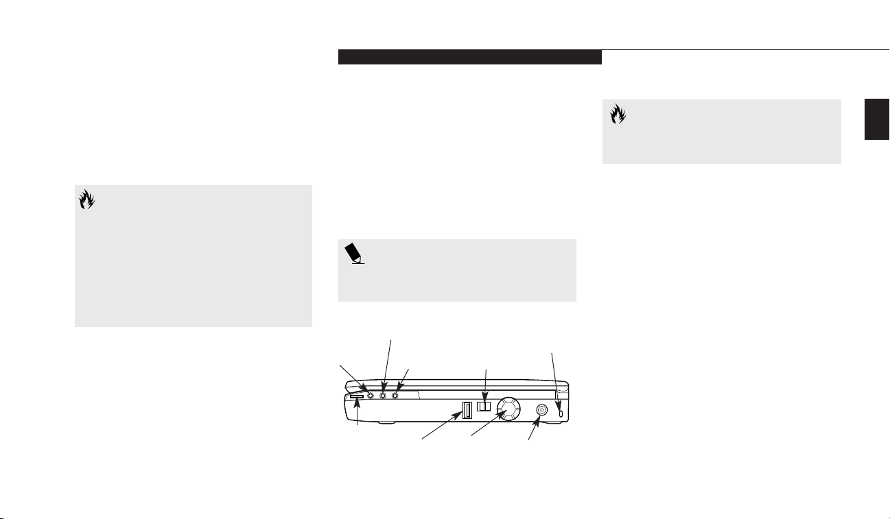
RIGHT-SIDE PANEL COMPONENTS
Volume Control
The volume control is a knob which provides
manual control of the sound level of all audio
output from your notebook. (Figure 1-9.)
Microphone Jack
The microphone jack allows you to connect an
external mono microphone. (Figure 1-9.)
USB Port
This port allows you to connect Universal
Serial Bus (USB) devices, such as external game
pads, pointing devices, keyboards and speakers.
(Figure 1-9.)
Power Switch
This switch is the main power switch for your
notebook. (Figure 1-9.)
DC Power Jack
The DC power jack allows you to plug in the
AC adapter or the optional auto/airline adapter.
(Figure 1-9.)
Theft Prevention Lock Slot
This slot allows you to attach a physical lock
down device, such as the optional Notebook
Guardian. (Figure 1-9.)
Figure 1-9 LifeBook E Series Right-side Panel
Stereo Line
In Jack
Microphone
Jack
Power Switch
Theft Prevention
Lock Slot
USB
Port
DC Power Jack
Volume
Control
Headphone
Jack
Fan
CAUTION
FAN: Do not block the circulation
of air flow.
CAUTION
There are also software volume controls.
The knob setting and the software
settings will interact. Software volume
off will override the knob setting and
the software volume setting will control
the maximum knob setting. (See Volume
Control on page 34 for more information.)
Headphone Jack
You can connect headphones or powered external speakers to the headphone jack.(Figure 1-9.)
Stereo Line In Jack
The stereo line in jack allows you to connect an
external audio source to your notebook, like an
audio cassette player. This jack will not support
an external microphone. (Figure 1-9.)
POINT
Windows NT 4.0 does not support USB
devices at this time.
Page 21
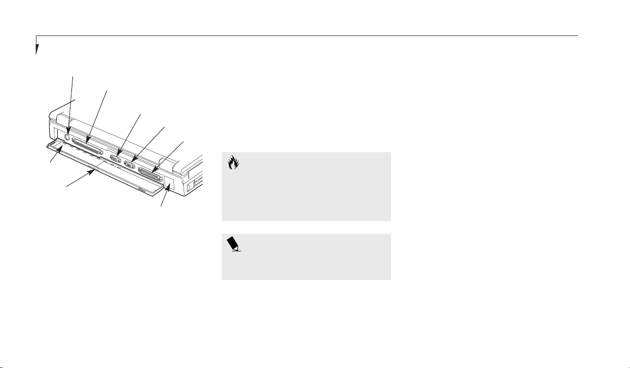
Figure 1-10 LifeBook E Series Rear Panel
Docking Port
External
Monitor Port
Serial Port
Parallel Port
Infrared Port
Connector Cover
Slide Panel
PS/2 Port
Section One
10
External Monitor Port
This port allows you to connect an external
VGA or SVGA monitor. (Figure 1-10.)
Serial Port
The serial port allows you to connect serial
RS-232C devices, such as serial printers or
serial scanners. (This is also sometimes
referred to as a COM port.) (Figure 1-10.)
Parallel Port
The parallel port allows you to connect
parallel devices, such as a parallel printer
to your notebook. (This is also sometimes
referred to as a LPT port.) (Figure 1-10.)
Infrared Port
The fast IrDA 1.1 (4Mbps) compatible port
allows you to communicate with another IrDA
compatible infrared device without a cable.
(See page 44 for more information.)
(Figure 1-10.)
Docking Port
This port is for connection to an optional port
replicator or docking station. The connector
cover must be closed and the sliding panel fully
opened to reveal the docking port and the
PS/2 port when connecting a port replicator
or a docking station. (Figure 1-10.)
CAUTION
The cover – which closes over the ports
on the rear of the notebook – can be
damaged if it is left open when the
notebook is moved around.
REAR PANEL COMPONENTS
PS/2 Port
The port allows you to connect an external PS/2
keyboard, mouse and/or numeric keypad. The
use of two PS/2 devices simultaneously from
the port requires a PS/2 splitter. (Figure 1-10.)
POINT
Windows NT 4.0 does not support
infrared communications.
Page 22

One
Setting Up Your LifeBook E Series
LifeBook E Series from Fujitsu
11
BOTTOM COMPONENTS
Tilt Adjustment Feet
These are a pair of feet which flip down and
hold the back of the notebook approximately
6° higher than the front when resting on a flat
surface. They are designed to make using your
notebook keyboard more comfortable.
(Figure 1-11.)
Memory Upgrade Compartment
This compartment houses the memory upgrade
module which allows you to expand the system
memory capacity of your notebook. (See pages
80-83 for more information on installing added
memory capacity.) (Figure 1-11.)
Main Unit and Configuration Label
This label shows the model number and other
information about your notebook. In addition
the configuration portion of the label has the
serial number and manufacturer information
that you will need to give your support representative so that he or she can help you. It identifies the exact version of various components
of your notebook. (Figure 1-11.)
Figure 1-11 LifeBook E Series Bottom
Memory
Upgrade
Compartment
Tilt
Adjustment
Feet
Main Unit
Label
Multi-function Bay 1
Release Button
Multi-function Bay 2
Release Button
Multi-function Bay 1 Release Button
This is the release to allow removal and
installation of devices in Multi-function Bay 1.
(Figure 1-11.)
Multi-function Bay 2 Release Button
This is the release to allow removal and
installation of devices in Multi-function Bay 2.
(Figure 1-11.)
Multi-function Bay 1
This compartment is accessed from the front of
your notebook. (See Figure 1-7 on page 6.)
Hard Drive Compartment
This compartment houses the primary
hard drive. (See Figure 1-11.)
HDD
Compartment
Page 23

Starting Your LifeBook E Series from Fujitsu
Section Two
Power Sources . . . . . . . . . . . . . . . . 14
Display Panel . . . . . . . . . . . . . . . . . 15
Adjusting the Keyboard Angle . . . . . . . . 15
Starting Your Notebook
for the First Time . . . . . . . . . . . . . . 16
Registering Your LifeBook . . . . . . . . . . 20
Learning About Your Operating System
and Application Software. . . . . . . . . . 21
Power Off . . . . . . . . . . . . . . . . . . 21
Restarting Your Notebook . . . . . . . . . . 22
Page 24
To Switch From AC Adapter Power or
Auto/Airline Adapter To Battery Power
1. Be sure that you have at least one charged
battery installed.
2. Remove the AC or auto/airline adapter.
Section Two
14
SECTION TWO
STARTING YOUR LIFEBOOK
E SERIES FROM FUJITSU
This section describes the processes of starting
your LifeBook for the first time, initial software
setup and registration.
POWER SOURCES
Your notebook has four possible power sources:
the primary Lithium ion battery; an optional
dual Lithium ion battery configuration; the AC
adapter; or an optional auto/airline adapter.
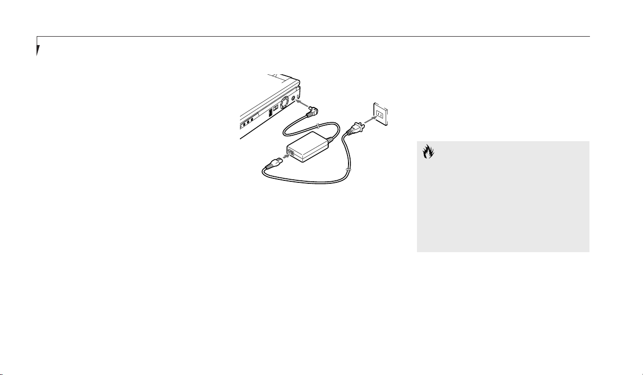
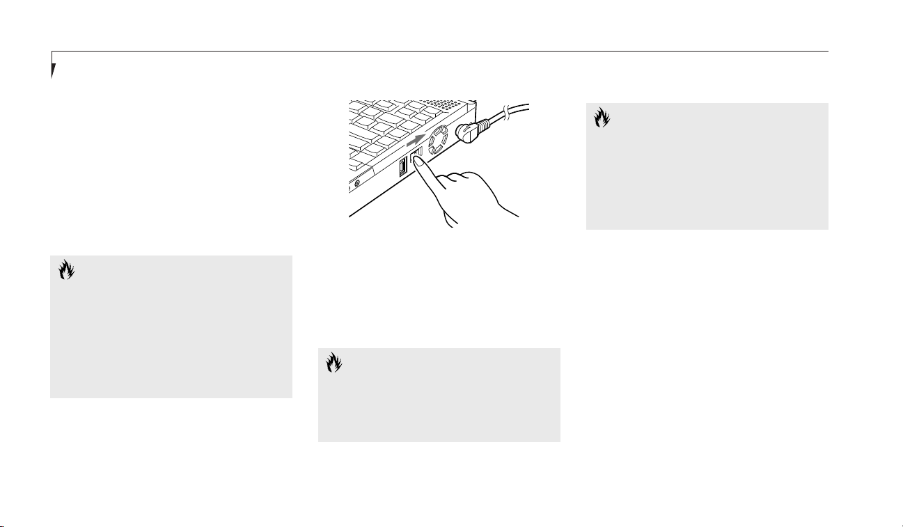
Connecting the Power Adapters
The AC adapter or an optional auto/airline
adapter provides power for operating your
notebook and charging the batteries.
To Connect the AC Adapter
1. Connect the two pieces as shown. (Figure 2-1.)
2. Plug the DC Output cable of the AC adapter
into the DC Power jack on the right-side
panel of your notebook.
3. Plug the AC adapter into an AC
electrical outlet.
To Connect the Optional Auto/airline Adapter
1. Plug the DC Output cable into the DC
Power jack on the right-side panel of
your notebook.
2. Plug the auto/airline adapter plug into the
cigarette lighter of a car or other vehicle with
the ignition key in the On or the Accessories
position or into the DC Power jack on an
airplane seat.
CAUTION
The primary Lithium ion battery is not
charged when you purchase your notebook. Initially you will need to connect the
AC adapter or the auto/airline adapter to
use it. If you purchase a second Lithium
ion battery it will not be charged when
you get it. You will need to charge it
prior to use.
Figure 2-1 Connecting the AC Adapter
Page 25
Two
Starting Your LifeBook E Series
LifeBook E Series from Fujitsu
15
DISPLAY PANEL
Opening the Display Panel
Lifting the latch releases the top of the display
panel from the front of the notebook body.
When the display panel is released it pops up
slightly to make it easier to open. Lift the display panel backward until the screen is at a
comfortable viewing angle. (Figure 2-2.)
Adjusting the Display Panel
Before you turn on your notebook, you may
want to adjust the brightness level of the screen.
Start with the brightness control slider (located
directly under the display screen) in the middle
position. (Figure 2-3.)
You may need to readjust the brightness levels
for different operating environments.
POINT
The higher the brightness level, the more
power the notebook will consume and
the faster your batteries will discharge.
For maximum battery life, make sure that
the brightness is set as low as possible.
ADJUSTING THE KEYBOARD ANGLE
On the bottom of your notebook, near the
back, are a pair of feet which flip down and
hold the back of the notebook about 6° higher
than the front when resting on a flat surface.
They are designed to make it more comfortable
to use the keyboard with your notebook. The
feet must be folded flat against the bottom
of the notebook when opening or using the
DVD/CD-ROM drive or it will not open or
operate properly.
Figure 2-2 Opening the Display Panel
Figure 2-3 Adjusting the Display
CAUTION
Do not operate your DVD/CD-ROM
drive or attempt to open the tray unless
your notebook is sitting on a flat surface
and the adjustment feet are folded
against the bottom of the notebook.
Using a DVD/CD-ROM drive when it
is not level may damage the drive or
prevent proper operation.
Page 26
CAUTION
When you turn on your notebook be
sure you have a power source. This
means that at least one battery is
installed and charged, or that the AC
adapter or the auto/airline adapter is
connected and has power.
When the power switch is turned on, your
notebook carries out a Power On Self Test
(POST) to check the internal parts and configuration. If a fault is found a beep will sound
and/or an error message will be displayed.
(See Troubleshooting on pages 110-112) Depending on the nature of the problem you may be
able to continue by starting the operating
system or by entering the BIOS setup utility
and revising the settings.
After satisfactory completion of the Power On
Self Test (POST) your notebook will load your
operating system.
Section Two
16
STARTING YOUR NOTEBOOK
FOR THE FIRST TIME
Power On
The power switch is located on the right side of
your notebook. This switch is used to turn On
the computer from its Off state. Once you have
connected your AC adapter or have charged the
internal Lithium ion Battery, you can power On
your notebook.
CAUTION
Do not carry your notebook around
with the power on or subject it to shocks
or vibration, as you risk damaging
your notebook.
book in Suspend mode, (see page 45), or you can
turn it off. The power switch moved toward the
front of your notebook is in the Off position.
(See the section Power Off, pages 21-22, for the
recommended shutoff procedures.)
CAUTION
The main Lithium ion battery is not
charged when you purchase your notebook. Initially you will need to connect
the AC adapter to use it. If you purchase
an optional second Lithium ion battery, it
will not be charged when you get it, you
will need to charge it prior to use.
Figure 2-4 Power On
Facing the keyboard and display panel, move the
power switch towards the rear of your notebook.
This is the On position. (See Figure 2-4.) When
you are done working you can leave your note-
Page 27

Two
Starting Your LifeBook E Series
LifeBook E Series from Fujitsu
17
CAUTION
Never turn off your notebook during
Power On Self Test (POST) or it will
cause an error message to be displayed
when you turn your notebook on the
next time. (See the Troubleshooting
information on pages 110-112.)
Booting the System with Windows 98
Second Edition
We strongly recommend that you not attach
any other external devices and do not put a
DVD, CD or floppy in any drives until you have
gone through the initial power on sequence.
When you turn on your notebook for the first
time, it will display a Fujitsu logo on the screen.
If you do nothing the system will read the hard
drive for the operating system software, flash
the notebook configuration information on the
screen, and then the Windows 98 SE Welcome
will begin.
Designed to accommodate the needs of many
users, in many different countries, Windows 98
SE needs to be configured for you the first time
you use it. The Windows 98 SE has four parts:
Getting Started – here you have the opportunity
to enter this custom information and setup
your phone so that your LifeBook will be prepared to dial out, Registration – easy on-line
registration for Windows 98 SE with Microsoft
and your LifeBook with Fujitsu PC Corporation,
Windows License – a required procedure to activate Windows 98 SE, and Final Settings –
Windows 98 SE takes the information you have
entered and makes your configuration. If you
need to stop the process, you may click on "cancel" on any screen, and Windows 98 SE will shut
down. You may restart the process at any time,
but you must complete it to use your LifeBook.
Getting Started
Read the instructions on the screens carefully,
and fill in the information as directed. You will
be asked for such items as the language you
wish to use, the country in which you live, your
first and last name, and about how you dial out
from where you will be using your computer.
For the phone settings, enter the information
for the location where you are setting up your
LifeBook. Windows 98 SE will help you dial
from other locations as they come up. If you
are not connected to a phone line and plan to
register your LifeBook at a later time, you may
click on "skip", and you will go directly to the
condition of use page.
Once you have setup your LifeBook to dial out,
Windows 98 SE will make a free telephone call
which will test these settings. If the call is
unsuccessful, you will be returned to the phone
settings page where you may try to fix them at
this time. If you are unable to fix the settings
please contact Fujitsu PC Service and Support.
(See page 90.) If you would simply like to move
on, and register your LifeBook at a later time,
simply click on "skip" and you will go directly
to the condition of use page.
Page 28

Section Two
18
Registration
If your connection is successful, you will go to
the Registration Confirmation page. On this
page simply enter the requested information,
and then check the box at the bottom to
register your copy of Windows 98 SE with
Microsoft. Once you have finished, click on
next to continue.
Final Settings
The first part of your final settings is the
Windows End User License Agreement. Read
the agreement carefully. You can scroll through
the text using your pointing device to activate
the scroll bar or use the up arrow Õ and the
down arrow Ô keys to move up and down the
text one line at a time, or use the Page Up and
Page Down keys to move the text one screen at
a time. When you finish reading you must
accept or reject the terms of the agreement and
then click on the Next > button.
Next you will need to enter your Windows
Product Key. Look in the box that your notebook came in and you will find a Windows 98
SE Certificate of Authenticity shrink wrapped
with the Windows 98 SE Users manual. On the
certificate you will find a bar-code with a number above it. This is your product key and the
number you need to enter on the Product Key
screen. When you have entered the number
exactly as shown click on the Next > button.
POINT
If you do not register at this time you can
do it later simply by double-clicking on
the LifeBook Registration icon on your
desktop, and following the instructions.
POINT
You cannot use your notebook until you
have accepted the License Agreement
and entered your product key. If you stop
the process your notebook will return to
the beginning of the Windows 98 SE
Welcome Process, even if you shut your
LifeBook down and start it up again.
You will then go into Fujitsu Registration.
Follow the instructions on the screens, and
enter all of the information so that if you
need help FPC service and support will be
able to serve you better.
POINT
If you reject the terms of the license
agreement you will be asked to review
the license agreement for information on
returning Windows 98 SE or to shut
down your notebook.
Wait for a few moments as Windows 98 SE
prepares for you. Once it is ready, your desktop
will appear, and you are ready to begin!
Page 29

Two
Starting Your LifeBook E Series
LifeBook E Series from Fujitsu
19
POINT
If you reject the terms of the license
agreement you will be asked to review
the license agreement for information on
returning Windows NT Workstation or to
shut down your notebook.
Registration
Look in the box that your notebook came in
and you will find a Windows NT Workstation
Certificate of Authenticity shrink wrapped with
the Windows NT Workstation Users manual.
On the certificate you will find a bar-code with
a number above it. This is your product ID
and the number you should enter on the
Registration screen. When you have entered
the number exactly as shown click on the
Next
>
button.
Computer Name
You need to enter a name for your computer to
be identified by on the network. This must be a
unique name and must be 15 characters or less.
Enter a name for your computer to be identified by and click on the Next
>
button.
Administrator Account
This screen lets you setup a password for the
Administrator account on your notebook. The
administrator account has authority over all
user accounts. You must not forget this password. If you do not wish to have password
Booting the System with Windows NT 4.0
We strongly recommend that you not attach
any other external devices and do not put any
DVD, CD or floppy disk in your drives until
you have gone through the initial power on
sequence.
When you turn on your notebook for the first
time it will display a Fujitsu logo on the screen.
If you do nothing the system will read the hard
drive for the operating system software, flash
the notebook configuration information on the
screen, and then the Windows NT 4.0 Setup
Wizard Screen will appear. You will then be
stepped through the condition of use process.
You must complete this initial process before
you will be able to use your notebook. (If you
wish to access the BIOS setup utility before you
go through the condition of use process you
must press the F2 key while the Fujitsu logo is
still visible. If you press the Esc key while the
Fujitsu logo is still present you will get a dialog
box which will allow you to select which drive
is to be used for finding the operating system.)
If you turn off the power without using the on
screen Cancel button you will get an error
message when you start your notebook again.
The following describes what you will be asked
to do at each of the five screens.
Windows NT Setup
The Windows NT Setup screen appears after
you accept the license agreement. This setup
wizard will guide you through the setup of your
Windows NT Workstation.
Name and Organization
Fill in your name and the company name as
you want the software licensed. To step from
the name blank to the company blank press the
Tab key.
When the information has been entered
click on the Next> button. You will not be
allowed to continue until you make an entry.
Page 30

Section Two
20
protection on your administrator account you
can leave this screen blank. When you have
entered and confirmed your password click on
the Next
>
button.
Windows NT Setup
Once you have setup your computer name and
your administrator account you can click on
the Next
>
button to finish the Windows NT
Workstation setup and begin installing
Windows NT networking. This will take your
notebook a few seconds and you will need to
reboot the system when it is complete.
REGISTERING YOUR LIFEBOOK
What are the benefits of registering?
You will receive an identification label for your
LifeBook, which, if your LifeBook is ever lost,
may help in getting it returned to you. You also
receive priority Personal Identification Number
(PIN) technical support access and useful product mailings. Proof of purchase is not required
if you register within 30 days of your purchase.
How do I register?
For Windows NT, you can register your system
through our on-line web site by double-clicking
the LifeBook Registration icon on the desktop.
You must have access to the Internet through an
Internet Service Provider to use this option.
With Windows 98 SE, it is a part of the Windows
98 SE Welcome process. If you do not register
during the Welcome process you can doubleclick on the LifeBook Registration icon on your
desktop and then follow the instructions.
POINT
You will find a Recovery CD-ROM packet
in your accessories box. Please store the
packet in a safe place in case there is a
loss of data, and it becomes necessary
to re-install your operating system and/
or application programs. (See Restoring
Your Pre-installed Software from the
Recovery CD-ROM on pages 114-115.)
POINT
Make sure you have connected a
phone line to your modem before
you use E-Registration.
You may also completed the pre-printed
registration form and either:
fax it to 1-949-450-9140
or mail it to:
Fujitsu PC Corporation
15355 Barranca Pkwy
Irvine, CA 92618-9520
or call: 1-800-8fujitsu (1-800-838-5487)
You may also register on our web site:
www.8fujitsu.com. You will need to be set up
with an Internet Service Provider (ISP) to
use this option.
Page 31

Starting Your LifeBook E Series
LifeBook E Series from Fujitsu
21
Two
POINT
You can register your LifeBook E Series
notebook with any operating system via
mail, telephone or fax.
clicking on the Fujitsu Service and Support
Web site URL link in the Service and Support
Software folder in the Windows Start menu.
familiar with the same application on a different machine, an earlier version of the application, or a similar product.
Manuals
In the accessories box you will find manuals for
your installed operating system and other
pre-installed software.
Software manuals of pre-installed software
that are not in the accessories box are available
online. See the help screens of your preinstalled software. We recommend that you
review these manuals for general information
on the use of these applications and to get a
basic understanding of what is covered in the
manual, and how it is organized, should
questions arise as you use the applications.
Links to Fujitsu On-line
You can go directly to the on-line Fujitsu
Accessories catalog for your notebook by clicking on the LifeBook Accessories Web site URL
link in the Windows Start menu. You can also
reach Fujitsu Service and Support on-line by
POINT
Please consult your User’s Guide for
specific information about the internal
modem and electronic registration for
the LifeBook E Series. Consult Microsoft
on-line documentation for specific information about the Windows Desktop and
Control Panel programs.
POINT
You must have an active internet
connection to use the on-line URL links
described in the Links to Fujitsu On-line.
LEARNING ABOUT YOUR OPERATING
SYSTEM AND APPLICATION SOFTWARE
Tutorials
All operating systems and most application
software have tutorials built-in. We highly recommend that you step through the tutorial
before you use an application even if you are
POWER OFF
Before turning off the power by putting the
power switch in the Off position, check that the
Hard Drive, DVD/CD-ROM, PC Card and the
Floppy Disk Drive Access indicators are all Off.
(See Figure 3-1, page 24.) If you turn off the
power while accessing a disk or PC Card there
is a risk of loss of data. The Off position is
reached by moving the power switch toward the
front of your notebook. To assure that your
notebook shuts down without error, use the
Windows shut down procedure.
Page 32

Section Two
22
CAUTION
Never turn your notebook off while an
application is running. Be sure to close all
files, exit all applications and shut down
your operating system prior to turning off
the power with the power switch. If files
are open when you turn the power off,
you will lose any changes that have not
been saved, and may cause disk errors.
POINT
When your notebook has been shut
down from Windows, it is not the same
as being turned off from the power
switch. It is in a pseudo-off state, with all
applications closed, but can and must be
turned on by pressing the Suspend/
Resume button. It is drawing some
current in the pseudo-off state.
Shutting down your notebook from Windows
lets your notebook shut down operations, and
turn off the power in the proper sequence to
prevent errors. The sequence is:
1. Click on the Start button.
2. Click on Shut Down.
3. Verify that Shut Down
is selected and click on Yes.
If you are going to store your notebook for a
month or more, take the following precautions:
1. Remove any CD and/or floppy disk.
POINT
You may also select Shut Down once the
power is off for 10 seconds or more you
can restart your notebook with the Suspend/
Resume button, or once the power is off,
turn the power switch to Off for 10 seconds
and then switch it to On. These alternative
methods are not recommended.
3. Click on Restart
4. Verify that Restart is selected and
click on Yes.
Windows will shut down and restart
your notebook.
2. After shutting down from Windows turn off
your notebook using the power switch.
3. Close your notebook display panel.
4. Disconnect the AC adapter.
5. Remove the batteries and store them
separately in a cool dry place.
CAUTION
Turning off the power switch without
exiting Windows may cause an error
when you start the next time. Turning
the power to On when it has been Off
for less than 10 seconds may also cause
an error when you start the next time.
RESTARTING THE SYSTEM
If your system is on and you need to restart it,
be sure that you use the following procedure.
1. Click on the Start button.
2. Click on Shut Down.
Page 33

Using Your LifeBook E Series from Fujitsu
Section Three
Status Indicator Panel. . . . . . . . . . . . . 24
Integrated Pointing Devices . . . . . . . . . 28
Using the Keyboard. . . . . . . . . . . . . . 32
Volume Control. . . . . . . . . . . . . . . . 34
Batteries . . . . . . . . . . . . . . . . . . . 34
Floppy Disk Drive. . . . . . . . . . . . . . . 38
SuperDisk 120 Drive . . . . . . . . . . . . . 40
CD-ROM Drive. . . . . . . . . . . . . . . . 40
DVD Drive . . . . . . . . . . . . . . . . . . 40
Hard Drive . . . . . . . . . . . . . . . . . . 42
Internal Modem . . . . . . . . . . . . . . . 43
Internal LAN . . . . . . . . . . . . . . . . . 43
Infrared Port . . . . . . . . . . . . . . . . . 44
Power Management . . . . . . . . . . . . . 44
Pre-installed Software . . . . . . . . . . . . 49
Data Security . . . . . . . . . . . . . . . . . 60
Boot Sequence . . . . . . . . . . . . . . . . 61
Identifying The Drivers . . . . . . . . . . . . 62
BIOS Setup Utility . . . . . . . . . . . . . . 62
Your Save-To-Disk File Allocation . . . . . . . 63
Page 34

Section Three
24
SECTION THREE
USING YOUR LIFEBOOK
E SERIES FROM FUJITSU
This section describes the indicators, buttons,
connections and operating modes of your
LifeBook E Series and their use.
STATUS INDICATOR PANEL
The Status Indicator panel is located in the
recess just above the keyboard. (Figure 3-1.)
The appropriate icon will appear to indicate
the activity of the corresponding component
in your notebook.
Power Indicator
The Power indicator tells you when the system
is operational. It is on steady when there is
power to your notebook, and blinks when the
system is in Suspend mode. It goes off when
the system has entered Save-to-Disk mode, or
the power is turned off from the power switch.
Figure 3-1 Status Indicator Panel
Power Battery
Identifier
DVD/CD-ROM
Drive Access
Hard Drive
Access
AC Adapter
Battery
Level
PC Card
Access Indicator
Floppy Disk
Drive Access
NumLk
CapsLock
ScrLk
Battery
Charging
PC
Card
Slot
Identifier
Page 35
Three
Using Your LifeBook E Series
LifeBook E Series from Fujitsu
25
POINT
When your notebook has been shut
down from Windows, it is not the same
as being turned off from the power
switch. It is in a pseudo-off state, with all
applications closed, but can be turned on
by pressing the Suspend/Resume button.
It is drawing some current in the
pseudo-off state.
battery is charging, the Power Adapter indicator
is active regardless of the setting of the power
switch. The AC Adapter indicator is also active if
you have shut down from Windows but have
not turned the power switch to Off. If there is
no battery charging, and the power switch is
Off, then the AC Adapter indicator and the
Battery indicators will all be Off.
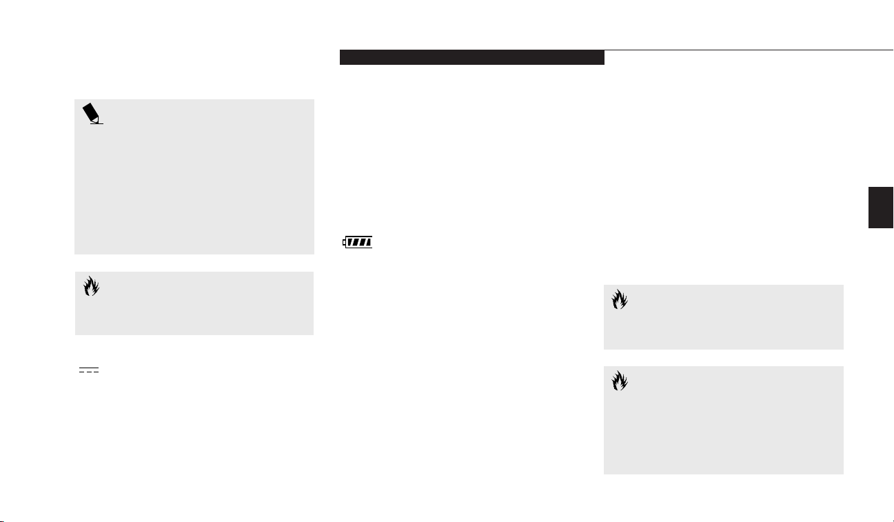
Battery Indicator
The two sets of battery indicators show whether
or not the primary Lithium ion battery and/or
the optional second Lithium ion battery are
installed, and indicate the condition of each.
(Figure 3-2.) Battery 1 is the Lithium ion battery which is installed in Multi-function Bay 1
and Battery 2 is the Lithium ion battery which
is installed in Multi-function Bay 2. The battery
indicators are displayed only for a battery which
is installed.
A small arrow icon (Battery Charging indicator) appears to the left of each of the Battery
Level indicators and above the number (Battery
CAUTION
Your notebook’s power switch must be
turned off to prevent all current draw.
identifier) if that battery is charging. The
Battery Charging indicator flashes if the battery
is too hot or too cold to charge. (Figure 3-2.)
The Battery Charging indicators operate
whether the power switch is Off or On.
The symbols inside the battery outline of the
Battery Level indicator show the operating level
available in that battery. (Figure 3-2.) If there is
no battery charging and the power switch is Off
then the AC Adapter indicator and the Battery
indicators will all be off.
AC Adapter Indicator
The AC Adapter indicator tells you whether the
system is operating on an AC or auto/airline
adapter, or batteries alone. The indicator is On
when either of the adapters is active and Off
when power comes from the batteries alone. If a
CAUTION
A shorted battery is damaged and must
be replaced. (See Figure 3-2.)
CAUTION
Turning off the power with the power
switch or using the Suspend/Resume
button when any of the Access indicators
are On may cause loss of data and/or
system errors.
Page 36

CAUTION
Batteries subjected to shocks, vibration
temperatures or extreme temperatures
can be permanently damaged.
DVD/CD-ROM Drive Access Indicator
The DVD/CD-ROM Access indicator tells
you the DVD/CD-ROM drive is being
accessed. The DVD/CD-ROM Access indicator
will flash when the software tries to access the
DVD/CD-ROM even if no DVD/CD-ROM
drive is installed.
Section Three
26
POINT
The Windows 98 SE DVD/CD automatic
insertion function will periodically check
for a DVD/CD installed in the drive,
causing the DVD/CD-ROM Access indicator to flash. The DVD/CD automatic
insertion function allows your system to
automatically start a DVD/CD as soon
as it is inserted in the drive and the tray
is closed. It will begin playing an audio
DVD/CD or will start an application
if the DVD/CD has an auto run file on it.
Figure 3-2 Battery Level Indicator
76%–100% Charging
76%–100%
51%–75%
26%–50%
13%–25%
Low Warning ≤12%
Dead Battery
Shorted Battery
POINT
If you do not wish to have the DVD/CD
automatic insertion function on you
can disable it.
To disable the DVD/CD automatic insertion
function for Windows 95/98 do as follows:
1. Save all data and close all applications.
2. Click on the Start button.
3. Click on Settings.
4. Click on the Control Panel. The control
panel window will be displayed.
5. Double click on the System icon. The system
properties dialogue box will be displayed.
6. Click on the Device Manager tab. The
device list will be displayed.
7. Click on the + to the left of the DVD/CDROM icon. The DVD/CD-ROM drive
manufacturer’s name and model will
be displayed.
Page 37

Three
Using Your LifeBook E Series
LifeBook E Series from Fujitsu
27
8. Double click on the DVD/CD-ROM drive
manufacturer’s name and model.
9. The DVD/CD-ROM drive manufacturer’s
name and model properties dialogue box
will be displayed.
10. Click on the Settings tab.
11. Click on the automatic insertion
notification box to toggle it off.
12. Click on OK.
13. Click on Close in the system properties
dialogue box.
14. Click on Yes in the system settings,
change pop-up to restart your notebook
and activate this change.
You can re-enable the function by repeating the
process except that step 11 will change the setting
to on.
Hard Drive Access or Removable
Media Drive Access Indicator
The Hard Drive Access indicator tells you when
either the internal hard drive, an optional
second hard drive or an optional Zip drive
is being accessed.
POINT
The Hard Drive Access indicator does
not show which hard drive or Zip drive,
is being accessed. It works the same for
any one.
PC Card Access Indicators
The PC Card Access indicators tell you when
your notebook is accessing a PC card. Card 1
is the bottom connector inside the slot and
Card 2 is the upper connector inside the card
slot. Type III cards are always Card 1 only.
The PC Card Access indicator will flash if
your software tries to access a PC Card even
if none are installed.
NumLk Indicator
The NumLk indicator tells you the internal keyboard is set in ten-key numeric keypad mode.
(See page 32 for more information on the numeric
keypad.) You can activate the NumLk mode by
pressing the NumLk/ScrLk key while holding
down the Shift key. Deactivate the setting the
same way that you activated it.
Floppy Disk Drive Access Indicator
The Floppy Disk Drive Access indicator tells you
when a floppy disk drive or SuperDisk drive is
being accessed. The Floppy Disk Drive Access
indicator will flash when your software tries to
access a floppy disk or SuperDisk even if no
floppy disk drive or SuperDisk drive is installed.
Page 38
Section Three
28
POINT
If you are using an optional external
numerical keypad pressing the NumLk
key will activate the external keypad
and the indicator will come on, without
changing the function of any keys on
your keyboard.
CapsLock Indicator
The Caps Lock indicator tells you when the
keyboard is set for all capital letters. Activate
the all capital letters setting by pressing the
CapsLock key on the keyboard. Deactivate the
setting the same way that you activated it.
ScrLk Indicator
The ScrLk indicator tells you when scroll lock
is active. You can activate the scroll lock by
pressing the NumLk/ScrLk key. Deactivate the
setting the same way that you activated it.
INTEGRATED POINTING DEVICES
ErgoTrac Pointing Device
The ErgoTrac pointing device is composed
of a short, comfortable, dish-shaped pointing
device and two buttons located in front of the
keyboard. The ErgoTrac pointing device has
Figure 3-3 ErgoTrac Pointing Device
Right Button
Left Button
Cursor Control
the function of a mouse, and moves the cursor
around on the screen – up, down, left and right.
A light pressure with the tip of your finger is all
that is required to operate the ErgoTrac. The
more pressure you use the faster the cursor will
move. The second part of the ErgoTrac pointing
Page 39
Three
Using Your LifeBook E Series
LifeBook E Series from Fujitsu
29
device – the buttons – function as mouse buttons, and the functions they perform depend
on the application you are running. Figure 3-3
shows the position of the ErgoTrac pointing
device and buttons.
POINT
An external mouse can be connected
to the PS/2 port on the back side of the
notebook, and used simultaneously with
the integrated pointing device. However,
if you boot the system with the PS/2
mouse connected the internal pointing
device will be disabled as specified in
your BIOS settings. You can set the
internal pointing device so that it is
always enabled.
Figure 3-4 Clicking
Left Click Left Double Click
Figure 3-5 Dragging
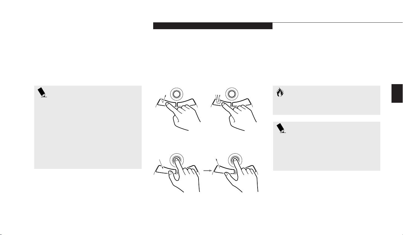
Double-Clicking
Double-clicking means following the preceding
Clicking procedure, but pressing the pointing
device button twice in rapid succession.
Double-clicking works only with the left button.
CAUTION
If the interval between clicks is too long,
double-clicking will not be executed.
Clicking
Clicking means pushing and releasing a button.
To left-click move the screen cursor to the item
you wish to select, press the left pointing device
button once, and then immediately release it.
POINT
The interval between presses for double
clicking, and other parameters of pointing
and selecting, can be adjusted with the
selections in the dialog box of the mouse
icon in your Windows Control panel.
To right-click, move the mouse cursor to the
item you wish to select, press the right pointing
device button once, and then immediately
release it. (Figure 3-4.)
Dragging
Dragging means moving the cursor over an
object, pressing the left button – and keeping it
pressed – while moving the cursor to the
desired new location, then releasing the button.
(Figure 3-5.)
Page 40

Section Three
30
A light pressure with the tip of your fingernail
is all that is required to operate the Touchpad.
Pencil erasers, etc. don’t work. The faster you
move your finger the faster the cursor will move.
The second part of the Touchpad pointing
device – the buttons – function as mouse buttons, and the functions they perform depend
on the application you are running. Figure 3-6
shows the position of the Touchpad and buttons.
Integrated Pointing Device
Control Adjustment
The Windows Control Panel provides customization of your pointing device from the mouse
icon. There are four (4) aspects of pointing
device operation which you can adjust.
■
Buttons – This lets you set up the buttons for
right or left handed operation and set the
time interval for double clicking.
■
Pointers – This lets you set up the size and
shape of the cursor for different functions.
■
Motion – This lets you set up the relation of
the speed of motion of your finger to the
motion of the cursor and to enable a trailing
tail for the cursor arrow.
■
General – This allows you to choose the type
of mouse being used. It is already set for your
integrated pointing device. You may need to
change it for an external mouse.
You may want to try practicing with different
adjustments until you find a combination that
is comfortable for you.
Touchpad Pointing Device
The Touchpad pointing device is composed
of a small rectangular touch sensitive pointer
control and two buttons located in front of the
keyboard. The Touchpad pointing device has the
function of a mouse, and moves the cursor
around on the screen – up, down, left and right.
Figure 3-6 TouchPad Pointing Device
Right Button
Left Button
Cursor Control
Page 41
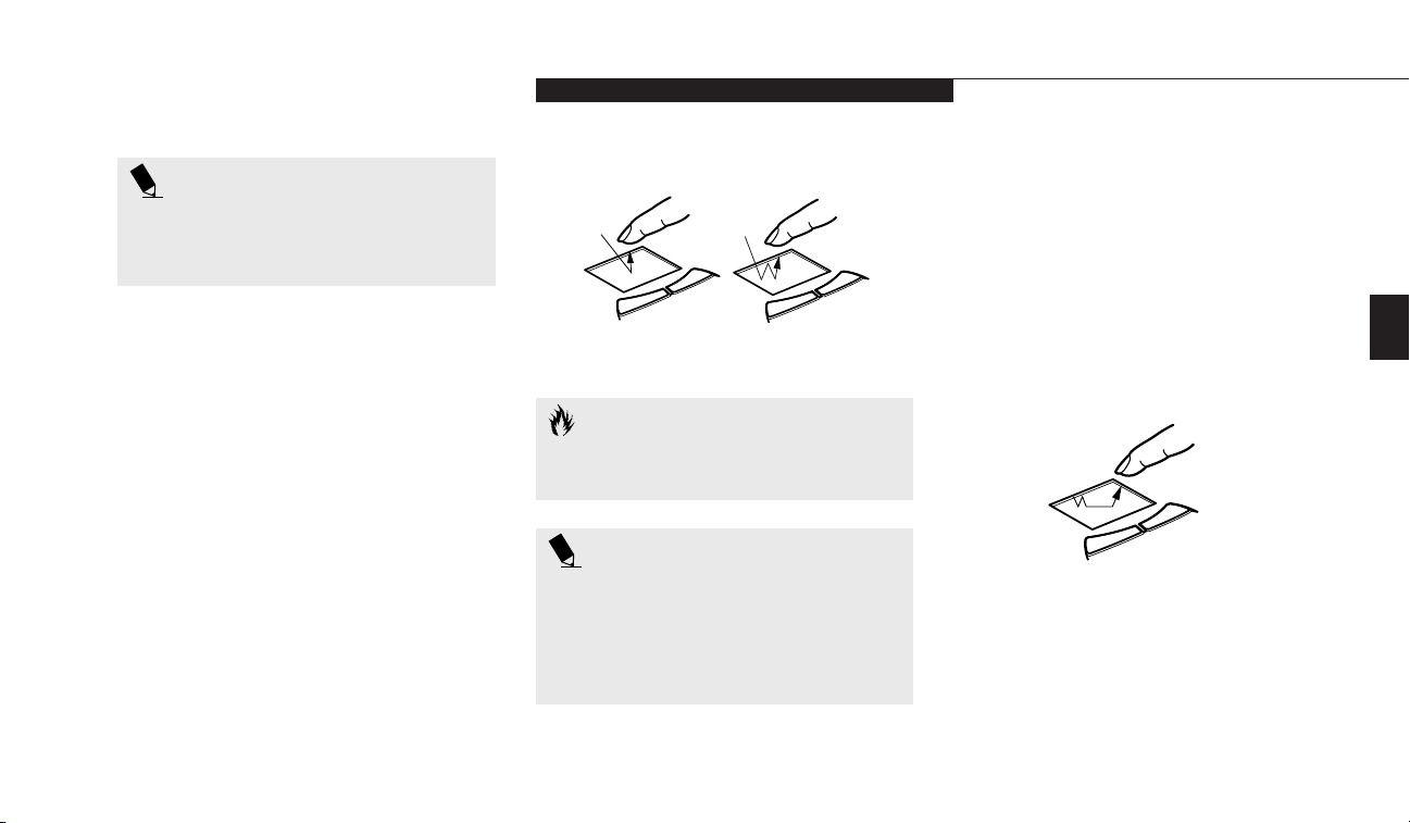
Three
Using Your LifeBook E Series
LifeBook E Series from Fujitsu
31
POINT
The left mouse button functions can
also be performed with your finger on
the Touchpad.
CAUTION
If the interval between clicks is too long,
the double-click will not be executed.
Clicking
Clicking means pushing and releasing a button.
To left-click, move the screen cursor to the item
you wish to select, press the left pointing device
button once, and then immediately release it.
To right-click, move the mouse cursor to the
item you wish to select, press the right pointing
device button once, and then immediately
release it. (Figure 3-7.) You can also left click by
a light tap on the Touchpad ending with your
finger off the pad, instead of using the button.
Double-Clicking
Double-clicking means following the preceding
Clicking procedure, but pressing the pointing
device button twice in rapid succession. Doubleclicking works with either the left or the right
button. You can also double left click by two
light taps on the Touchpad ending with your
finger off the pad, instead of using the button.
POINT
The interval between clicks for double
clicking, and other parameters of pointing
and selecting, can be adjusted with the
selections in the dialog box of the mouse
icon in your Windows Control panel.
Left-Click
Figure 3-7 Clicking
Left Double-Click
Dragging
Dragging means selecting an item with the
pointing cursor, and while keeping the left
pointing device button depressed, moving the
cursor to the desired new location, then releasing the button. (Figure 3-8.) Dragging can also
be done on the Touchpad—two light taps ending with your fingernail on the pad and then
moving, or holding the left button down and
moving your fingernail on the pad.
Figure 3-8 Dragging
Page 42
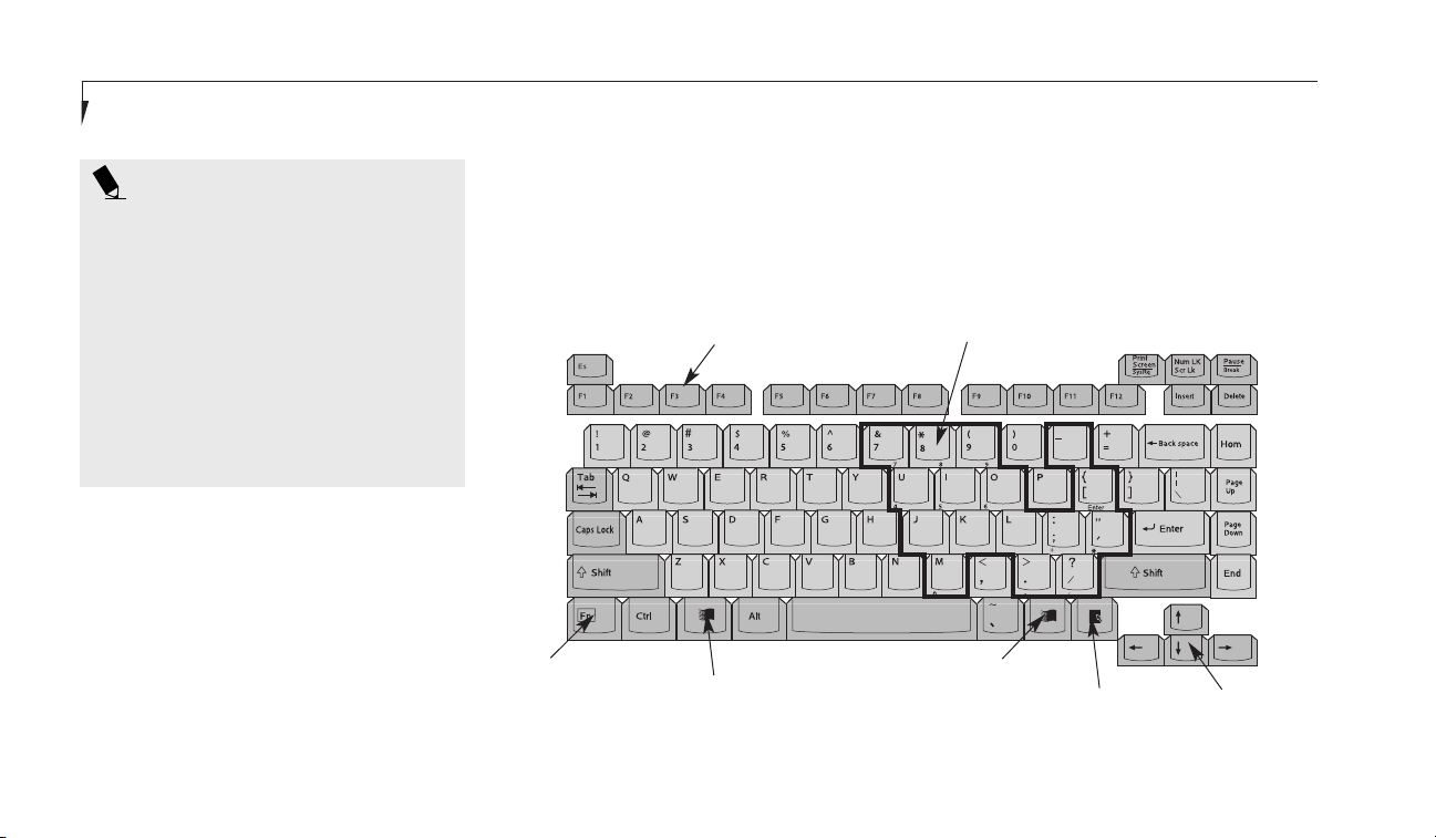
Section Three
32
Numeric Keypad
Certain keys on the keyboard perform dual
functions as both standard character keys and
numeric keypad keys. Figure 3-9 highlights
these keys. To switch into numeric keypad
POINT
For your convenience, we have included
the Alps GlidePoint mouse driver for
your integrated Touchpad device on
our Recovery CD. Locate your Recovery
CD in the accessories box. Insert the
Recovery CD into your system while the
operating system is active and through
My Computer or Windows Explorer,
locate the directory D:\Drivers\Touchpad.
Follow the directions in the readme file in
this directory to install the optional driver.
USING THE KEYBOARD
Your notebook has an integral 86-key keyboard.
(Figure 3-9.) The keys perform all the standard
functions of a 101-key keyboard and also
include Windows keys and other special function keys. This section describes only those
items specific to your notebook. They are the
numeric keypad, the cursor keys, the function
keys, the function extension key (Fn) and the
Windows keys.
Figure 3-9 Keyboard
Function Keys
Numeric Keypad
Fn Key
Start Key
Start Key
Application Key
Cursor Keys
mode, press the NumLk/ScrLk while holding
down the Shift key.You can now enter numerals
0 through 9, perform addition ( + ), subtraction
( – ), multiplication ( * ), or division ( / ), and
enter decimal points ( . ) using the keys
Page 43

Three
Using Your LifeBook E Series
LifeBook E Series from Fujitsu
33
designated as ten-key function keys. The keys in
the numeric keypad are marked on the front
edge of the key to indicate their secondary
functions.
To return these keys to their normal character
function, press the NumLk/ScrLk while holding
down the Shift key again.
POINT
If you are using an optional external
numerical keypad pressing the NumLk
key will activate the external keypad
and the indicator will come on, without
changing the function of any keys on
your keyboard.
Cursor Keys
The cursor keys are the four arrow keys on the
keyboard which allow you to move the cursor
up Õ, down Ô, left Ó and right È in applications; in windows such as the Explorer window,
it moves the "focus" (moves to select the next
item up, down, left, or right).
POINT
The integrated pointing device and/or
external mouse are also used for moving
the cursor around the screen.
Function Keys
Your notebook has 12 function keys, F1
through F12. The functions assigned to these
keys differ for each application. You should
refer to your software documentation to find
out how these keys are used. (See Figure 3-9.)
Fn Key
The Fn key provides extended functions for the
notebook and is always used in conjunction
with another key. (See Figure 3-9.)
Pressing F5 while holding down the Fn key
allows you to toggle between video compensation and no compensation. (Video compensation controls spacing on the display. When it is
enabled, displays with less than 1024 x 768 or
800 x 600 pixel resolution will still cover the
entire screen.)
Pressing F6 repeatedly while holding down the
Fn key will lower the brightness of your display.
Pressing F7 repeatedly while holding down the
Fn key will increase the brightness of the display.
Pressing F10 while holding down the Fn key
allows you to change your selection of where to
send your display video. Each time you press the
combination of keys you will step to the next
choice. The choices, in order, are: built-in display panel only, both built-in display panel and
external monitor, or external monitor only.
Pressing the Suspend/Resume button while
holding down the Fn key will activate the
Save-to-Disk mode. (Please see pages 46–48
for information regarding this feature.)
Windows Keys
Your notebook has three Windows keys, two
Start keys and an Application key. The Start key
displays the Start menu. This is the same as the
button on the toolbar which is typically at the
bottom of your Windows desktop. The
Application key has the same function in
Page 44

controls to set an upper limit on sound level
and then make fine adjustments with other
application software.
Section Three
34
Windows as the right mouse button, it displays
the Shortcut menu for whatever item is selected. See your Windows documentation for additional information. (See Figure 3-9.)
VOLUME CONTROL
All system and application functions have multiple volume controls which interact with each
other. There is the hardware volume control on
the right side panel of your notebook. There is
a volume control in the ESS AudioRack, your
operating system Sound Control panel and any
other application with sound.
Each setting source puts an upper limit on the
volume which can be set by the other sources.
For example if the hardware volume control is
turned all the way down, your software volume
control settings have no effect. By the same
token, if the ESS AudioRack has the sound
turned off, adjusting the hardware or other
application software volume settings will not
produce sound. One easy operating method is
to use the hardware and ESS AudioRack volume
CAUTION
The ESS AudioRack volume setting
sets the maximum volume level of
the hardware volume control knob.
notebook in Suspend mode, remove the low
battery and quickly insert a charged battery.
(See page 35 for more information about the
bridge battery.)
The Lithium ion battery operating time may
become shorter if it is used under the
following conditions:
■
When used at temperatures that exceed a
low of 5°C or a high of 35°C. High temperatures not only reduce charging efficiency,
but can also cause battery deterioration.
(The Charging icon on the Status Indicator
panel will flash when you try to charge
a battery that is outside its operating
temperature range.)
■
The battery charging capacity is reduced as
the battery ages. If your battery is running low
quickly, you should replace it with a new one.
■
When using a high current device such as a
modem, a LAN card, a CD-ROM drive, or
the hard drive frequently.
POINT
Windows NT 4.0 does not support the
ESS AudioRack application.
BATTERIES
The Lithium ion batteries are rechargeable. Your
notebook can be operated on the primary
Lithium ion battery alone or in a dual battery
configuration with a second Lithium ion battery. A built-in bridge battery allows a charged
Lithium ion battery to be exchanged for a discharged one by "warm-swapping". To warmswap, have a charged battery ready, put your
Page 45

Three
Using Your LifeBook E Series
LifeBook E Series from Fujitsu
35
Using the AC adapter will conserve your battery when using a high current device such as a
modem, a LAN card, a CD-ROM drive, or the
hard drive frequently. The Bridge battery can
only be recharged by using the AC adapter.
CAUTION
Actual battery life will vary based on
screen brightness, applications, features,
power management settings, battery
condition, and other customer preferences. CD-ROM drive or hard drive
usage may also have a significant
impact on battery life.
CAUTION
Do not leave a faulty battery in your
notebook. It might damage your AC
adapter, optional auto/airline adapter,
another battery, or your notebook itself.
It may also prevent operation of your
notebook by draining all available current
into the bad battery.
CAUTION
Under federal, state or local law it
may be illegal to dispose of batteries by
putting them in the trash. Please take
care of our environment and dispose
of batteries properly. Check with your
local government authority for details
regarding recycling or disposing of
old batteries. If you cannot find this
information elsewhere, contact your
support representative at 1-800-8FUJITSU
(1-800-838-5487).
Bridge Battery
The bridge battery is a NiCad battery that is
built into your notebook and is constantly
being recharged under AC Power. A bridge
battery allows a charged Lithium ion battery
to be exchanged for a discharged one by
"warm-swapping".
To warm-swap have a charged battery ready,
put your notebook in Suspend mode, remove
the low battery and quickly insert a charged
battery. The bridge battery capacity is not
large, about 3 minutes, and can vary with the
condition of your notebook.
CAUTION
Data may be lost and/or system
errors introduced if the warm swap
is not performed quickly.
Page 46
finish charging or discharging before the other
if they were not at the same charge level when
they were installed and/or the AC or auto/
airline adapter was connected.
There is no memory effect on the Lithium ion
batteries, which means that you do not need to
discharge them completely before recharging,
this is called "trickle charging." Of course partially charged batteries will not take as long to
charge. The charge times will be significantly
longer if your notebook is in use while the batteries are charging. For approximate charging
times see Self Help on our Service and Support
web site at www.8fujitsu.com. Once there click
on Self Help Center. Using the pull-down menus
select E Series, then select Specifications, then
your unit.
Section Three
36
CAUTION
Using heavy current devices such as LAN
cards or frequent CD-ROM accesses may
prevent charging completely.
CAUTION
The bridge battery can not support an
operating notebook. The notebook must
be in Suspend mode.
Shorted Batteries
If your Status Indicator panel shows a shorted
battery, check the installation for that battery
by removing and re-installing it. If it still shows
that it is shorted, replace it with a new battery.
CAUTION
A shorted battery is damaged and must
be replaced so that it does not damage
anything else.
change. Battery 1 is a Lithium ion battery which
is installed in Multi-function Bay 1 and Battery
2 is a Lithium ion battery which is installed in
Multi-function Bay 2. (Figure 3-1 on page 24.)
The Lithium ion batteries are recharged internally using the AC adapter or auto/airline
adapter. To recharge the batteries:
■
Make sure the battery to be charged is
installed in either Multi-function bay of
your notebook and connect the AC or
auto/airline adapter.
■
Make sure that the Battery Charging indicator to the left of the Battery Level indicator
of the battery to be charged is visible on the
Status Indicator panel.
■
Make sure the percentage charge is shown
inside the Battery Level icon. (Figure 3-2
on page 26.)
When two Lithium ion batteries are installed,
the charge/discharge rate of the primary and
optional second Lithium ion batteries are the
same, as they are connected in parallel and are
both charging and/or discharging at the same
time. Since the rates are the same, one may
Recharging the Batteries
If you want to check the condition of either the
primary Lithium ion battery or an optional second Lithium ion battery, check the Battery Level
indicators located on the Status Indicator panel.
These indicators change as the battery levels
Page 47

Three
Using Your LifeBook E Series
LifeBook E Series from Fujitsu
37
CAUTION
You may not be able to hear the audio
alarms if the volume control is set too
low or is turned off by either hardware
or software but you will still be able to
see the Battery Level indicator(s) flash.
When the low battery alarm occurs you need to
save all your active data and put your notebook
into Suspend mode until you can provide a
new power source. You should provide this
power as soon as possible. The new power
source can be a charged battery or a power
adapter, either AC or auto/airline.
Once your notebook goes into Dead Battery
Suspend mode you will be unable to resume
operation until you provide a source of power
either from an AC adapter, an optional auto/
airline adapter, or a charged battery. Dead
Battery Suspend mode shows on the Status
indicator just like the normal Suspend mode.
Once you have provided power, you will need
to press the Suspend/Resume button to resume
operation. In the Dead Battery Suspend mode,
your data can be maintained for some time, but
if a power source is not provided promptly, the
Power indicator will stop flashing and go out,
and you will have lost the data that was
not stored.
Once you provide power you can continue to use
your notebook while an adapter is charging the
battery, but the battery trickle charges under
these conditions. If you want to charge the
battery more quickly, put your notebook into
Suspend mode, or turn off your notebook while
the adapter is charging the battery. (See Power
Off on pages 21-22 for shutdown procedures.)
Low Battery State
When the battery is running low, your notebook beeps about every 15 seconds and the
Battery Level indicator(s) flash. If you do not
respond to the low battery alarm, the batteries
will continue to discharge until they are too low
to operate. When this happens there will be a
multiple beep alarm, the Battery Level indicator
will show dead battery, and your notebook will
go into Suspend mode to try and protect your
data as long as possible. Your power management settings do not affect what happens at the
dead battery alarm level. Your notebook will go
into Suspend mode.
CAUTION
When you are in Suspend mode there
must always be at least one power source
active. If you turn off the power with
the power switch, or remove all power
sources, battery, AC adapter or auto/
airline adapter, while your notebook is in
Suspend mode any data which has not
been saved to the hard drive will be lost.
CAUTION
There is no guarantee that data will not
be lost once your notebook enters the
Dead Battery Suspend mode.
Page 48

Section Three
38
FLOPPY DISK DRIVE
The modular floppy disk drive is a 3.5" drive
which can read and write on 1.44MB and
720KB memory capacity floppy disks. Floppy
disk format is controlled from your operating
system. (See your software documentation for
more information.) The modular floppy disk
drive can be used in Multi-function Bay 1 or
externally with the FDD adapter
. The system
will treat any floppy disk drive in exactly the
same way regardless of where it is installed.
(For floppy disk drive installation and removal
instructions see Multi-function Bays on pages 7071 and External Installation of the Modular
Floppy Disk Drive on pages 79-80.) When your
system boots it will always look first for a floppy
disk drive in a Multi-function Bay 1, and then
look at the external floppy disk drive port.
Loading a Floppy Disk
To load, insert a floppy disk into the floppy disk
drive, shutter side first and label up, until the
Eject button, above the floppy disk drive
opening, pops out. (Figure 3-10.)
POINT
When there is no floppy disk in the
drive, the Eject button is flush with the
front of your notebook.
Ejecting a Floppy Disk
To eject a disk, check that the Floppy Disk
Drive Access indicator is Off, (see pages 24
and 27) and press the Eject button.
(Figure 3-10.)
Figure 3-10 Loading/Ejecting a Floppy Disk
CAUTION
If you eject the disk while the Floppy
Disk Drive Access indicator is On, there
is a risk of damaging the disk, the data
on the disk or the disk drive.
Page 49

Three
Using Your LifeBook E Series
LifeBook E Series from Fujitsu
39
Preparing a Floppy Disk for Use
Before you can use a new floppy disk, you need
to prepare it so your notebook knows where to
store information. This preparation is called
formatting or initializing a disk. You need to
format new 3.5" floppy disks, unless you purchase preformatted disks. You will use your
CAUTION
Formatting a previously used floppy
disk is an effective method of clearing a
disk as long as you realize that ALL the
information on the disk will be erased.
■
Keep the floppy disk drive and disks
out of direct sunlight and away from
heating equipment.
■
Avoid storing the floppy disk drive in
locations subject to shock and vibration.
■
Avoid using the floppy disk drive and disks
in damp and dusty locations.
■
Never use the floppy disk drive with any
liquid, metal, or other foreign matter inside
the floppy disk drive or disk.
■
Never store a floppy disk near a magnet or
magnetic field.
■
To clean, wipe the floppy disk drive clean
with a dry soft cloth or with a soft cloth
dampened with water or a solution of
neutral detergent. Never use benzene, paint
thinner, or other volatile material.
■
Never disassemble or dismantle your floppy
disk drive.
Figure 3-11 Floppy Disk Write Protect
Write Enabled
Write Protected
notebook's operating system software to format
a floppy disk. Please refer to the operating system manual for step-by-step instructions.
To prevent data stored on a floppy disk from
being erased, slide the write protect tab on the
floppy disk to open up the small hole. This
makes the disk "write protected". When you
want to write data to that disk, slide the write
protect tab the other way to close the small
hole.(Figure 3-11.)
Care of Floppy Disk Drives and Disks
■
Avoid storing the floppy disk drive and
disks in extremely hot and cold locations,
or in locations subject to severe
temperature changes.
Page 50

Section Three
40
CD-ROM DRIVE
The modular CD-ROM drive is a 24x
maximum reader. (Figure 3-13.)
DVD DRIVE
The modular DVD Drive is a 2x maximum
reader and takes the place of the CD-ROM
drive in Multi-Function Bay 2. It works very
much like a CD-ROM drive in that it can read
CD-ROMs as well as DVDs. It can also play
Audio CDs. (Figure 3-13.)
CAUTION
Do not operate your DVD/CD-ROM
drive unless your notebook is sitting on
a flat surface and the adjustment feet
are folded against the bottom of the
notebook. Using a DVD/CD when the
drive is not level may damage the drive
or prevent proper operation.
SUPERDISKTM120 DRIVE
The modular SuperDisk drive is a floppy disk
drive that can read and write both 120MB
Super floppy disks and standard 1.44MB and
720KB floppy disks. It takes the place of a
floppy drive and offers greater removable
media storage capabilities. (Figure 3-12.)
The SuperDisk drive works very much like a
regular floppy disk drive in your LifeBook E
Series. Please refer to the Floppy Disk Drive
section for usage and care information.
Figure 3-12 SuperDisk Drive
Figure 3-13 DVD/CD-ROM Drive
POINT
Windows NT 4.0 does not support
video playback from either DVDs
or CD-ROMs.
Page 51

Using Your LifeBook E Series
LifeBook E Series from Fujitsu
41
Loading a DVD or CD
■
Make sure that the angle adjustment feet on
the bottom of the notebook are folded
against the bottom of the notebook.
■
Make sure there is power to your notebook.
■
Push, gently but firmly, and release the eject
button on the front of the drive to open
the holder tray, the tray will come out a
short distance. (Figure 3-14.)
■
Gently pull the tray out until a DVD/CD can
be easily placed in the tray.
■
If there was a protective sheet in the tray
when it was shipped, make sure it
has been removed.
■
Place the DVD/CD into the tray, label side up,
with the hole in the center of the DVD/CD
snapped onto the raised circle in the center
of the tray.
■
Close the tray.
■
After the DVD/CD is loaded, it will take a
short time for your notebook to recognize it.
POINT
If you have disabled your DVD/CD
automatic insertion function you will
have to start the DVD/CD from your
desktop, as your notebook will not automatically recognize that the DVD/CD has
been loaded.
Three
Care of DVDs and CD-ROMs
DVDs and CD-ROMs are precision devices and
will function reliably if given reasonable care.
■
Always store your DVD/CD-ROM in its case
when it is not in use.
■
When removing the DVD/CD-ROM from its
case, press down on the holder’s center while
lifting out the DVD/CD-ROM by its edges.
■
Always handle a DVD/CD-ROM by the edges
and avoid touching the surface.
■
Avoid storing any DVD/CD-ROM in
extreme temperatures.
■
Do not bend DVDs/CD-ROMs or set heavy
objects on them.
Figure 3-14 Loading the DVD/CD-ROM Tray
Page 52
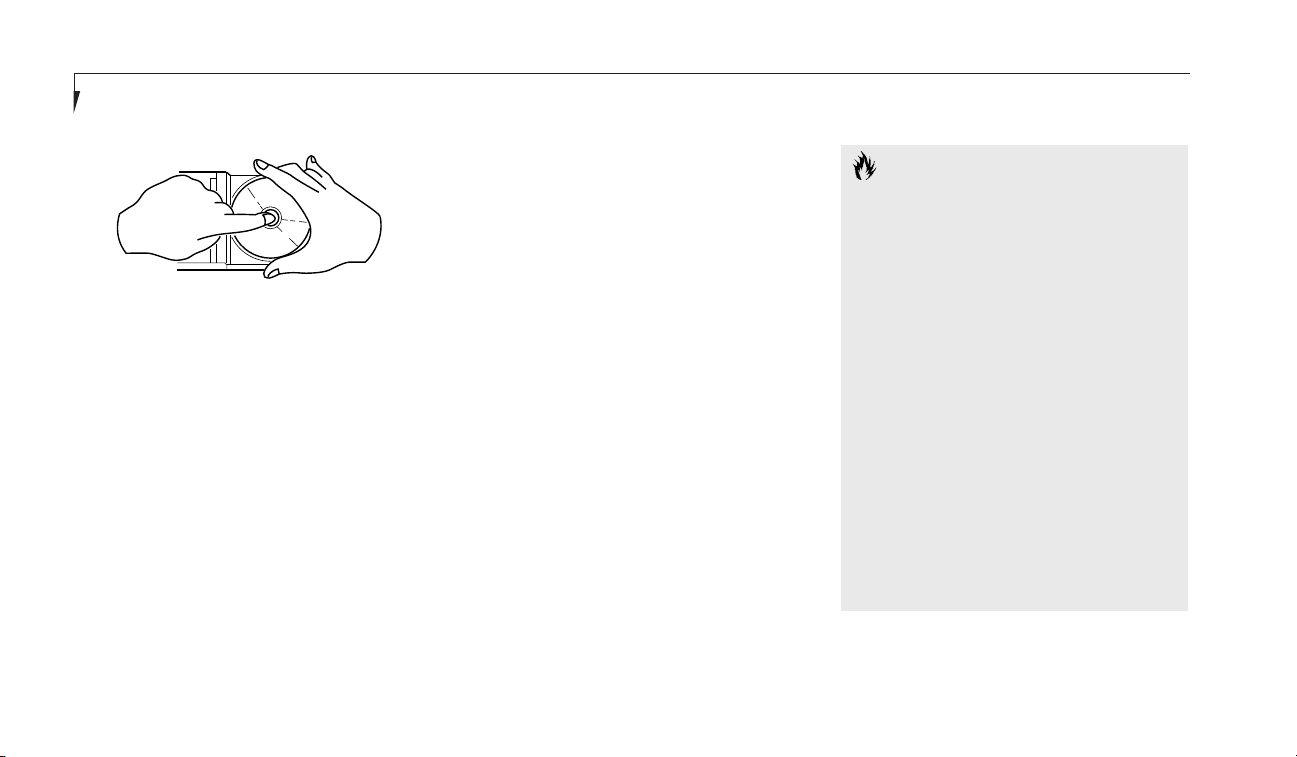
Section Three
42
■
Never write on the label surface with a ball
point pen, pencil or similar device.
■
If a DVD/CD-ROM is subjected to a sudden
change in temperature, cold to warm condensation may form on the surface. Wipe the
moisture off with a clean, soft, lint free cloth
and let it dry at room temperature. DO
NOT use a hair dryer or heater to dry a
DVD/CD-ROM.
■
If a DVD/CD-ROM is dirty, use only a
DVD/CD-ROM cleaner or wipe it with a
clean, soft, lint free cloth starting from the
inner edge and wiping to the outer edge.
CAUTION
If you reformat the internal hard drive
ALL data including the operating system,
applications software and data will be
erased. Unless data is copied to floppy
disks or other data storage media it will
be permanently lost. All software will be
need to be re-installed and data files
restored from your back-up disks. See
the operating system manual for more
information on backing-up your data
files. The factory installed software,
including the operating system, can be
restored from the Recovery CD-ROM
which came in the accessories box when
you purchased your notebook. (See
Restoring Your Pre-installed Software
from CD-ROM on page 114 for more
information.) Any application software
which you have purchased and installed
HARD DRIVE
The internal hard drive capacity is dependent
on which model you are using. See Appendices
(pages 122–125) or your packing label for model
information. If you are using the optional second hard drive for the first time since you
installed it, you can get your notebook to recognize it by opening the Windows Control Panel
and opening Add New Hardware which will
step you through the process of having
Windows look for your newly installed device.
Formatting the Hard Drive
The hard drive inside your notebook is formatted (initialized) at the factory. You do not need
to format it under normal circumstances. If
you purchase an optional second hard drive
you will need to Fdisk and format it before you
use it the first time. Check your operating
system documentation for information on
initializing a hard drive.
Figure 3-15 DVD/CD-ROM Handling
Page 53

Using Your LifeBook E Series
LifeBook E Series from Fujitsu
43
will have to be re-installed from the
original source. When doing a recovery
remember that you must allocate space
for the Save-to-Disk function if you
have it enabled. (See Your Save-to-Disk
File Allocation on pages 63-66 for
more information.)
CAUTION
The internal modems on all Fujitsu E Series
notebooks from Fujitsu PC Corporation
are not qualified for use with telephone
systems outside the United States
and Canada and may not operate
in other countries.
CAUTION
The internal modem is designed to the
ITU-T V.90 standard. Its maximum speed
of 53000bps is the highest allowed by
the FCC, and its actual connection rate
depends on the line conditions. The
maximum speed is 33600bps at upload.
Three
INTERNAL MODEM
Your LifeBook is configured with a K56Flex
fax/data/voice modem with V.90 support.
Figure 3-16 Internal Modem or LAN
CAUTION
The internal modem is not intended for
use with Digital PBX systems. Do not
connect the internal modem to a digital
PBX as it may cause serious damage to
the internal modem or your entire notebook. Consult your PBX manufacturer’s
documentation for details. Some hotels
have Digital PBX systems. Be sure to find
out BEFORE you connect your modem.
INTERNAL LAN
If your LifeBook is configured with an internal
LAN daughter card, it is a Fast Ethernet
(10/100 Base-T/Tx) network interface with an
RJ-45 connector. Your internal LAN card will
need to be configured for use in the Windows
network control panel. Please refer to your
systems administrator for information on
your particular network configuration.
Page 54

Section Three
44
INFRARED PORT
Infrared IrDA-compatible communication is a
function that allows for wireless data transfer
between your notebook and other IrDA-compatible devices. Examples of IrDA-compatible
devices are another computer or a printer. When
carrying out this kind of communication, both
devices must be set so their infrared ports are
directly facing each other without obstructions.
A distance of 6" to 36" between the device ports
is ideal. Dirt or scratches on the lens of your
notebook or the other device will degrade
performance. This is especially true for Fast IrDA
applications such as a transfer to an Ethernet.
If you are using Windows 98 SE, you can use the
Infrared Recipient program for infrared file transfers. LapLink Professional software can also be
used for infrared file transfers in Windows 95
and Windows 98 SE. See your online help menus
for more information.
POINT
Windows NT 4.0 does not support the
infrared port on your LifeBook E Series.
CAUTION
Be careful not to scratch the infrared
port lens. Scratches, dirt or other surface
marks can effect operation.
■
When a strong light such as direct sunlight,
fluorescent light, or incandescent light shines
on the port.
The following conditions may interfere with
infrared communications:
■
When the infrared communication ports
are not directly facing each other, or some
obstacle is between them.
■
When the infrared communication ports
are too far apart.
■
When a television or radio remote control
unit, or a wireless headphone is being
used nearby.
CAUTION
Do not move either device during
communication as it may interrupt
data transmission.
POWER MANAGEMENT
Your LifeBook E Series has many features for
conserving battery power. Some power savings
features are automatic and have no user control, such as those for the internal modem,
while others depend on the parameters you
set to best suit your operating conditions.
Other power saving features turn the display
brightness down, limit the use of high power
devices, activate an appropriate power savings
profile, and put your notebook in Suspend
mode when not actually performing an
operation. As with all mobile, battery-powered
computers, there is a trade-off between
performance and power savings.
Page 55

Three
Using Your LifeBook E Series
LifeBook E Series from Fujitsu
45
Internal power management for your notebook
may be controlled from settings made in the
BIOS setup utility, prebundled power management application, or from settings made in
your operating system.
Using the Suspend/Resume Button
When your notebook is active, the Suspend/
Resume button can be used to manually
put your notebook into Suspend mode. The
Suspend/Resume button is located next to the
Status Indicator panel above the keyboard
of your notebook. (Figure 3-17.) Push the
Suspend/Resume button, when your notebook
is active but no Access indicators are on and
release the button (immediately). You will hear
two short beeps and then your system will
enter Suspend mode.
If your notebook is suspended, pushing the
Suspend/Resume button will return your notebook to active operation at the point where it
went into suspension. You can tell whether or
not your system is in Suspend mode by looking
at the Power indicator. (See page 24.) If it is visible and not flashing, your notebook is fully
operational. If it is visible and flashing, your
notebook is in Suspend mode. If it is not visible, the power is Off or your notebook is in
Save-to-Disk mode. Your notebook will be
set to operate in Suspend mode when you
receive it.
Suspend Mode
The Suspend mode, or Standby mode in
Windows 98 SE, saves the contents of your
notebook’s system memory during periods of
inactivity by maintaining power to critical parts
while turning off the CPU, the display, the hard
drive and all of the other internal components
except those necessary to maintain system
memory and recognize the Suspend/Resume
button and restart. Your notebook can be
put in Suspend mode by:
■
Pressing the Suspend/Resume button when
your system is in the On state.
■
Selecting Standby from the Windows Shut
Down menu (Windows 98 SE).
■
Selecting System Suspend from the
PowerPanel toolbar menu (Windows 95
and Windows NT).
■
Timing out from lack of activity.
■
Battery level reaching the Dead Battery
Warning condition.
Figure 3-17 Suspend/Resume Button
CAUTION
Loss of all power sources, including
batteries, while in the Suspend mode will
cause lost data and inability to return
to operation with the Suspend/
Resume button.
Page 56

Your notebook’s RAM typically stores the file(s)
on which you are working, the open application(s) and any other data required to support
the operation(s) in progress. When you resume
operation from Suspend mode, it returns to
the point in the operation where it left off.
You must use the Suspend/Resume button
to resume operation, and there must be an
adequate power source available, or your
notebook will not resume.
Using the Suspend/Resume Button to
Perform Save-to-Disk
The Save-to-Disk function saves the contents of
the notebook's system memory to the hard
drive as a part of the Suspend/Resume function.
Your notebook is setup to perform this function
in one way–two for Windows 95 and NT– and
can be configured through the system BIOS to
do it in other ways.
Default Methods for using Save-to-Disk mode:
■
Press the Fn key together with the
Suspend/Resume button when activating the
Suspend mode. The Save-to-Disk pop-up will
appear on your screen, simply wait until it
has finished and your notebook will go into
Save-to-Disk mode.
■
Windows 95 and NT users may also activate
the Save-to-Disk mode through their
PowerPanel toolbar.
Customer configured BIOS methods:
■
Press the Suspend/Resume button until
acknowledged with Save-to-Disk mode
enabled from the Power menu of the
BIOS setup utility.
■
Select Standby from the Windows Shut
Down menu with Save-to-Disk enabled by
the BIOS Setup Utility.
(Windows 98 SE only.)
■
Time out from lack of activity with Save-ToDisk mode enabled from the Power Savings
menu of the BIOS setup utility.
Your notebook’s system memory typically stores
the file(s) on which you are working, the open
application(s) and any other data required to
support the operation(s) in progress.
Section Three
46
CAUTION
Be sure you know which settings are
active for the Suspend/Resume button
before you use it; misuse can result in
data loss. (See the Power Menu in
the BIOS Guide, see pages 62-63 for
more information.)
POINT
Disabling the Suspend/Resume button
prevents it from being used to put your
notebook in Suspend or Save-to-Disk
mode. The resume function of the button cannot be disabled. (See the Power
Savings Menu in the BIOS Guide, see
pages 62-63 for more information.)
Page 57

Using Your LifeBook E Series
LifeBook E Series from Fujitsu
47
Three
POINT
Save-to-Disk mode will not operate
when Resume On Modem Ring has
been selected in the BIOS.
POINT
If your notebook is active when you
enter the Suspend or Save-to-Disk mode,
changes to open files are not lost. The
files are left open and memory is kept
active during Suspend mode or the
memory is transferred to the internal
hard drive during Save-to-Disk mode.
POINT
When PC Cards or external devices are
in use, Save-to-Disk mode cannot return
to the exact state prior to suspension,
because all of the peripheral devices will
be re-initialized when the system restarts.
CAUTION
The Suspend or Save-to-Disk mode
should not be used with certain PC
Cards. Check your PC Card documentation for more information.
CAUTION
If you are running your notebook on
battery power, be aware that the battery
continues to discharge while your notebook is in Suspend mode, though not as
fast as when fully operational. With a
fully charged internal Lithium ion battery
the Suspend mode will maintain your
status for 24 hours or more.
POINT
The main advantage of using the
Save-to-Disk function is that power is
not required to maintain your data. This
is particularly important if you will be
leaving your notebook in a suspended
state for a prolonged period of time. The
drawback of using Save-to-Disk mode
is that it lengthens the power down and
power up sequences and resets
peripheral devices.
Page 58

Section Three
48
POINT
Save-to-Disk mode requires allocating a
significant amount of hard drive capacity
for saving all system memory, which
reduces your usable disk space. When
you purchase your notebook it will have
space allocated for the memory installed.
If you upgrade the original system by
adding a memory upgrade module
without changing the size of your Saveto-Disk allocation you will get an error
message when you try to activate Saveto-Disk mode and it will not work. Use
the PHDISK Utility to increase the size
of the Save-to-Disk file, SAVE2DSK.BIN.
(Refer to Your Save-to-Disk File
Allocation on pages 63-66 for
more information.) If you need help
contact your support representative
for recommendations.
Idle Mode
Idle mode is one of the power management
parameters. When Idle mode is enabled the
CPU is put into low-speed operation when
there is no activity (keystroke, pointer action,
sound generation, video display change,
modem transmission or reception, etc.) on your
notebook for 16 seconds. Any activity will cause
the normal operation to restart automatically.
This feature is independent of the
Suspend/Resume modes. This parameter is
enabled and disabled in the BIOS setup utility.
(See pages 62-63.)
Standby Mode
Standby mode is one of the power management
parameters. When Standby mode is activated,
your notebook puts the CPU in low-speed
operation, shuts off the display and turns off
the hard drive when there is no activity (keystroke, pointer action, sound generation, video
display change, modem transmission or reception, etc.) on your notebook for the user selected time-out period. (See page 62.) Any activity
will cause your notebook to return to normal
operation automatically. This feature is independent of the Suspend/Resume button. This
parameter is enabled and disabled in the BIOS
setup utility.
POINT
The Idle mode and Standby mode features described above are only available
in Windows NT. Windows 98 SE has its
own integrated power management features that include the functionality of
those listed above.
Video Timeout
The Video Timeout is one of the power management parameters which saves power by
turning off the display if there is no keyboard
or pointer activity for the user selected timeout
period. Any keyboard or pointer activity will
cause the display to restart automatically. This
feature is independent of the Suspend/Resume
button. This parameter is enabled and disabled
in the BIOS setup utility. (See page 62.)
Page 59

Three
Using Your LifeBook E Series
LifeBook E Series from Fujitsu
49
Hard Disk Timeout
The Hard Disk Timeout is one of the power
management parameters which saves power
by turning off the hard drive if there is no hard
drive access for the timeout period which has
been set in the BIOS setup utility. Any attempt
to access the hard drive will cause the hard
drive to restart automatically. This feature is
independent of the Suspend/Resume button.
This parameter is enabled and disabled in the
BIOS setup utility.
Windows Power Management
Control Panels
The Power Management icon in the Windows 98
SE Control Panel allows you to configure some
of the power management settings that are normally controlled by the BIOS. For instance, you
can set timeout values in the Power
Management Control Panel for turning off the
display and for turning off hard disks. You can
specify these timeout values based on whether
you are running on batteries or AC.
ACPI and Windows 98 Second Edition
Short for Advanced Configuration & Power
Interface, a power management specification
developed by Intel, Microsoft, and Toshiba.
ACPI, which is part of the Windows 98 SE
operating system, enables the operating system
to control the amount of power given to each
device attached to the computer. With ACPI,
the operating system can turn off peripheral
devices, such as CD-ROM players, when they
are not in use.
Due to ongoing industry development of
ACPI technology, we have configured your
LifeBook E Series notebook to APM
(Advanced Power Management) mode.
PRE-INSTALLED SOFTWARE
Your LifeBook E Series comes with preinstalled software for playing audio and video
files of various formats. In addition there is file
transfer software, virus protection software, and
Power Management software.
All of the pre-installed software can be accessed
from the Program folder of the Windows Start
menu. If you aren’t sure what software is preinstalled check the Program folder. If you need
assistance with an individual application use
their online help.
Windows 98 Second Edition
Windows 98 SE is an update to Windows 98
that enhances the operating system with the
latest Internet, home-networking and hardware
technologies. Enhancements include Internet
Explorer 5, NetMeeting 3 (conferencing software that allows you to share applications and
send audio and video.), improved Universal
Serial Bus (USB) support, and Internet
Connection Sharing (ICS) a set of advanced
home networking technologies that enable
multiple users to share a single connection to
the Internet.
Page 60
Section Three
50
Windows NT Workstation 4.0
Windows NT Workstation 4.0 combines the
Windows 95 interface with the power of
Windows NT. Features include 32-bit Windows
technology, Windows Messaging Client,
Microsoft Internet Explorer and built-in
TCP/IP Networking Support
PC Doctor
PC Doctor by Watergate Software is primarily
for use by your support representative when
helping you with trouble shooting.
POINT
You can modify the set up of certain
audio parameters in the BIOS setup utility,
Advanced Menu – Multimedia Device
Configuration Submenu. (See the Self
Help Center of our web site at
www.8fujitsu.com.)
ESS AudioRack™
The control of the AudioRack player software
(AudioRack32) resembles the front panels of
a rack of stereo equipment and is operated in
much the same way. There is also AudioRack
recorder software (AudioRecorder). Online
help screens are accessible from the AudioDrive
panel of AudioRack32, click on the Help button
for more information. In the AudioRecorder
dialog box, click on Help in the top taskbar.
In AudioRack32 the AudioDrive panel lets
you turn on and off the available functions.
When you left-click on a button it will activate.
When a function is active, its button on the
AudioDrive shows a green dot and its control
panel is in the equipment rack. When it is off
the dot on the button is black and the control
panel is not in the rack. You activate a slider or
knob on a control panel by dragging it. The
functions available are DAT (Digital Audio Tape
player), 3D (3D-Stereo sound control), MIDI,
Mixer and CD (Audio CD player).
ESS AudioRack is pre-installed on Windows 98
SE systems only.
POINT
For maximum frequency response and
bandwidth, leave the graphic equalizer
levels at the mid-point (zero level). To
customize the frequency response to
your personal taste, adjust accordingly.
CAUTION
The ESS AudioRack volume settings
set the maximum volume level of the
hardware volume control knob for
that function.
LapLink Professional
LapLink Professional, by Traveling Software, file
transfer software provides direct file transfers to
other computers. Data transfers can be via internal modem, a PC Card modem, the infrared
port, USB port, a serial cable, or a parallel cable
(cables are not included). (See the LapLink online
help screens for operating instructions.)
Page 61

Three
Using Your LifeBook E Series
LifeBook E Series from Fujitsu
51
LapLink Professional is pre-installed on
Windows 98 SE systems only.
Card Executive
Card Executive, by Phoenix Technologies allows
you to configure PCMCIA cards in Windows
NT 4.0. Consult the on-line documentation for
information on how to use this program.
Card Executive is pre-installed on Windows NT
4.0 systems only.
McAfee VirusScan
Running your McAfee VirusScan program after
loading data or programs from a floppy disk,
CD-ROM, modem data transfer, or infrared
data transfer is a precaution that will protect
the data on your hard drive from contamination or destruction. See your VirusScan online
help screens or online manual for information
on how and when to run this program.
The PowerPanel icon looks like an atom with
its cloud of electrons. This icon will open the
PowerPanel menu. You can view the menu in
icon format along the edge of your desktop by
moving the cursor against the edge where you
have chosen to keep your PowerPanel toolbar
and letting it sit there until the toolbar appears.
(The default position for the toolbar is the left
side of the screen, but you can move it to
whichever edge you like by dragging.)
The power management toolbar has ten power
profile choices and six activation choices.
When you switch to AC powered operation the
PowerPanel toolbar will automatically change to
indicate AC power operation and will show the
AC Power profile as active.
The profiles are groups of system settings
designed to fit power operation to specific user
operating conditions. The activations are shortcut ways to turn on specific power management
features of your notebook. Some of the profiles
can be edited and saved from the PowerPanel
application, some can be edited and saved from
PMSet 98
PMSet 98 is a power management application
which allows you to monitor battery status. See
your online help screens for information on
how to use the program.
PMSet 98 is pre-installed on Windows 98 SE
systems only.
POINT
As your LifeBook E Series does not support LCD Backlighting control and CPU
Clock control, these options are not
selectable in the Power Control ta
of PMSet98.
PowerPanel
PowerPanel by Phoenix Technologies provides
Windows desktop access to a comprehensive
combination of power management settings
without entering the BIOS setup utility.
PowerPanel is pre-installed on Windows NT
systems only.
Page 62

Section Three
52
POINT
The AC Power profile is activated automatically when a power adapter is being
used, unless it is overridden by another
selection made after the adapter became
active. It can be reactivated by selecting it
or it can be activated by selection, even
when operating only on battery power.
The activation choices are:
■
System Suspend.
■
System Save-to-Disk.
■
System Standby.
■
Hard Disk Standby.
■
Modem Power Toggle.
■
Video Standby.
The factory set Maximum Power Savings profile
is designed around trade offs of performance
and battery life. For true maximum battery life
keep the display and volume levels as low as
possible and use the custom settings recommended in the BIOS Guide.
the BIOS setup utility and only viewed from
PowerPanel, and some are factory set and can
only be viewed from either PowerPanel or the
BIOS setup utility.
The profile choices are:
(This group is factory set.)
■
Maximum Battery Life.
■
Maximum Performance.
■
Power Management Off.
(This one is set only from the
BIOS setup utility.)
■
Custom Settings.
(This group is set from PowerPanel.)
■
Presentation.
■
Green PC.
■
AC Profile.
■
Word Processing.
■
Communication.
■
Games.
POWERPANEL ONLINE HELP
To access help with your power management
settings, move your cursor to the PowerPanel
toolbar and right click. (See Clicking on pages
29 and 31.) From the menu that appears select
PowerPanel Help Topics.
POWERPANEL CUSTOMIZATION
To modify your PowerPanel toolbar or create
a custom toolbar, move your cursor to the
PowerPanel toolbar and right click. From the
menu that appears select Customize. Within the
Customize dialog box you can choose to have
the toolbar display at all times or to use your
custom toolbar. You can also select from the
same menu to Hide the toolbar. If you hide the
toolbar you will have to double click on the
edge where the toolbar was located to display it.
If you select Exit from the PowerPanel
menu you will turn off the PowerPanel completely. To turn it back on, go to the Program
folder of the Start menu, select PowerPanel and
click on it.
Page 63

Three
Using Your LifeBook E Series
LifeBook E Series from Fujitsu
53
MAXIMUM BATTERY LIFE PROFILE
The Maximum Battery Life profile is a factory
installed combination of timeouts and other
power savings parameters read directly from
the BIOS, and chosen as the settings that will
produce the longest possible battery life.
MAXIMUM PERFORMANCE PROFILE
The Maximum Performance profile is a factory
installed combination of timeouts and other
power savings parameters
read directly from
the BIOS and
chosen as the settings that will
produce superior performance with reasonable
battery life.
POWER MANAGEMENT OFF
Turns off power management control from
Windows and PowerPanel and turns it over
directly to the BIOS.
CUSTOM SETTINGS PROFILE
The Custom Settings profile has those power
saving parameters that you set in the BIOS
setup utility using the Power Savings Menu
Customize feature.
POINT
The Maximum Power Savings, Maximum
Performance, and Power Management
Off profiles are read only. The Custom
Settings Profile can only be changed
from the BIOS setup Utility.
AC PROFILE
The AC power profile has all timeouts disabled
and no other power management features
enabled. This profile is activated automatically
by plugging in a power adapter.
WORD PROCESSING PROFILE
The Word Processing profile is a factory
installed combination of timeouts and other
power savings parameters chosen as the settings
that will produce superior performance with
reasonable battery life when using your notebook for doing word processing.
COMMUNICATION PROFILE
The Communication profile is a factory
installed combination of timeouts and other
power savings parameters chosen as the settings
that will produce superior performance with
reasonable battery life when using your notebook with the modem active such as during
Internet or fax activities.
PRESENTATION PROFILE
The Presentation profile is the same combination of timeouts and other power savings parameters as the Maximum Battery Life profile
except that the display is never turned off.
(This profile was designed to enhance the
use of your notebook for slide show
style presentations.)
GREEN PC PROFILE
The Green PC profile has the Video timeout
and the Hard Drive timeout enabled but no
standby or suspension modes enabled.
Page 64

Section Three
54
GAMES PROFILE
The Games profile is a factory installed combination of timeouts and other power savings
parameters chosen as the settings that will produce superior performance with reasonable battery life when playing games on your notebook.
SYSTEM SUSPEND ACTIVATION
Clicking on the Suspend button or selecting
System Suspend on the PowerPanel menu will
put your notebook in Suspend mode. Pressing
the Suspend/Resume button turns the power
back on and lets you begin where you left off.
(See page 45.)
SYSTEM SAVE-TO-DISK ACTIVATION
Clicking on the Save-to-Disk button or selecting System Save to Disk on the PowerPanel
menu will put your notebook in Save-to-Disk
mode. Your notebook will be left in the
Windows 95 pseudo-off state. If the power
switch is not turned off your notebook can be
restarted by pressing the Suspend/Resume button which will cause the system memory to
reload from the hard drive and let you begin
where you left off. (See Figure 3-17 on page 45,
and Save-to-Disk Mode on pages 46-48.)
SYSTEM STANDBY ACTIVATION
Clicking on the System Standby button or
selecting System Standby on the PowerPanel
menu will put your notebook in Standby mode.
You can return your notebook to normal operation by performing any activity such as pressing
a key or touching the pointing device.
HARD DISK STANDBY ACTIVATION
Clicking on the Hard Disk Standby button or
selecting Hard Disk Standby on the PowerPanel
menu will turn off your internal hard drive. You
can return your notebook to normal operation
by performing any hard drive operation.
MODEM POWER TOGGLE
Clicking on the Modem Power Toggle button
or selecting Modem Power Toggle on the
PowerPanel menu will turn the power to your
modem on or off. To turn it to the other condition select Modem Power Toggle again.
VIDEO STANDBY ACTIVATION
Clicking on the Video Standby button or selecting Video Standby on the PowerPanel menu
turns off the power to the display. You can
return your notebook to normal operation by
performing any activity such as pressing a key
or touching the ErgoTrac pointing device.
Agaté Tioman Hot-Swap
Tioman allows you to hot-swap your LifeBook
E Series peripheral devices in the Multi-function Bays of your notebook, by turning off the
IDE interface to the bays to allow safe removal
of devices while the system is active and turning the IDE interface on again once new devices
have been inserted properly. Note: Tioman is
pre-installed on Windows 98 SE systems only.
Tioman supports the hot-swapping of the
following devices in the respective bays.
Multi-function Bay 1:
■
3.5" floppy disk drive.
■
Lithium ion Battery (while AC Adapter is
plugged in to notebook or while using a
second battery).
Page 65

Using Your LifeBook E Series
LifeBook E Series from Fujitsu
55
Three
about 'My Computer' and 'Windows Explorer')
associated with the devices you removed and
replace the drive letters in 'My Computer' and
'Windows Explorer' with designators for the
newly inserted devices. The 'Taskbar Icon'
and 'ToolTip Balloon' will be updated to reflect
the current devices inserted in the bays.
Note: The information in this section provides
a general description of how the Tioman
software functions. For specific instructions
on hot-swapping devices see the section
'Removing and Inserting Devices'.
Tioman Taskbar Icon
When your system is running in Windows you
will notice that small bay icons are contained in
the 'System Tray' in the lower right hand corner
of the Windows desktop. The left icon corresponds to Multi-function Bay 1 and the right
icon to Multi-function Bay 2. These taskbar
icons provide the quickest way to hot-swap
your notebook devices, (See the next section
'Removing and Inserting Devices' for specific
details) as well as acting as visual cues for the
current inserted devices. Hover over either icon
with the pointing device cursor and the
'ToolTip Balloon' will display the name of the
inserted device. Right-click on either icon to
display a menu which offers choices for swapping devices, accessing help menus, displaying
properties for the inserted device and providing
information about the Tioman software.
Use the following table as a guide to identify
which 'ToolTip Balloon' names are associated
with your Multi-function Bay devices:
De
vice ToolTip Balloon
Floppy Disk Diskette drive in bay
Drive
Battery Battery in bay
CD-ROM CD-ROM drive in bay
(Multi-function Bay 2 only)
DVD DVD drive in bay
(Multi-function Bay 2 only)
Weight Saver Weight Saver
(Multi-function Bay 2 only)
2nd Hard Drive Hard drive in bay
(Multi-function Bay 2 only)
■
Optional SuperDisk drive.
Multi-function Bay 2:
■
24x maximum CD-ROM drive.
■
Optional 2x maximum DVD drive.
■
Lithium ion Battery w/ Adapter (while AC
Adapter is plugged in to notebook or while
using a second battery).
■
Weight Saver.
■
Optional Second 6.4GB hard drive.
■
Optional Iomega Zip 100 drive.
(Standard with E370 and E380.)
General Guidelines for Using Tioman
Tioman allows you to exchange removable
devices without suspending the system by
turning off the IDE interface to both Multifunction Bays simultaneously. At this point
the system is still active but in a safe mode
where you may swap a single device out of
either Multi-function Bay, swap devices in
both Multi-function Bays or do nothing. The
software will remove all drive letters from 'My
Computer' and 'Windows Explorer' (Consult
Windows' on-line help menus for information
Page 66

POINT
The A: drive letter will never be removed
from the "My Computer” and "Windows
Explorer” folders, because the floppy
drive is not considered a removable
device by Windows.
Section Three
56
POINT
Due to the special design and configuration of the Iomega Zip 100 drive the
'ToolTip Balloon' identifier may vary.
Please consult the documentation that
comes with your Optional Iomega Zip
100 drive for specific information on how
to properly configure and use the device
with Agate Tioman software.
POINT
Due to the special design of the SuperDisk
120 Drive it can be configured as a
removable device as well as a standard
bootable floppy drive. Because of this
unique configuration the ‘ToolTip Balloon’
identifier for the SuperDisk 120 Drive may
vary. Please consult the documentation
that comes with your Optional SuperDisk
120 Drive for specific information on how
to properly configure and use the device
with Agate Tioman software.
Removing and Inserting Devices
1. Close any open files on the removable
device(s) that you plan to eject from
the computer.
2. Right-click on either 'Tioman Taskbar Icon'
to display its menu.
3. Select the 'Swap Devices' menu. (You can
also select the 'Properties' menu item to
bring up the 'Device Bay Properties' window
where you can activate the 'Swap Devices'
button from the 'Bay 1' or 'Bay 2' property
sheets or you can simply double-click either
'TaskBar Icon' to bring up the 'Device Bay
Properties' window)
4. The 'Agate Tioman' window will pop up and
display the following message: It is now
safe to remove and insert devices
in either Multi-function Bay.
After you have completed device
swapping, click the OK button.
5. You can now safely remove both devices
from both bays or one device from either bay
without damage to the computer or
the device(s).
6. References to both devices' drive letters listed
under 'My Computer' and 'Windows Explorer'
will automatically be removed even if you only
removed one device.
7. The 'Taskbar Icons' will display a blue and
white bar which indicates that you should
remove a device or devices if you haven't
already, and the 'ToolTip Balloons' will be
changed to read 'Remove xxx in bay' where
xxx refers to the device(s) you should
be removing. Note: Tioman does not require
that you actually remove a device or devices
Page 67

Using Your LifeBook E Series
LifeBook E Series from Fujitsu
57
when the Taskbar Icons are marked with a blue
and white bar. If you change your mind you
can continue by pressing the OK button.
8. You can now safely insert new devices into
both bays or one device into either bay without damage to the computer or the device(s)
as long as you have not pressed the OK
button at this point.
9. Press the OK button after inserting the new
device to continue.
10. The software will automatically detect the
new devices and place them online.
Note: The software will always re-detect both
devices even if you only swapped one device or
you decided not to swap any devices at all.
11. All drive letters associated with both devices
will be re-created and listed under 'My
Computer' and 'Windows Explorer'.
12. The 'Taskbar Icons' and 'ToolTip Balloons'
will be updated to reflect the new devices
inserted in the bays.
Three
If you happen to press the OK button before
inserting a device into Multi-function Bay 1,
Tioman will display the following message:
No device detected in Bay 1.
Please insert a device before
clicking the Continue button.
You must insert a device into Multi-function
Bay 1 to continue at this point. If you choose
to cancel the warning message, Tioman will
prompt you to insert a device in Multi-function
Bay 1 the next time the 'Swap Devices'
command is run.
CAUTION
Make sure whenever you use Agate
Tiomon Hot-Swap software that you
always have at least one battery installed
in either Multi-function Bays of your
E Series notebook when you are running
on battery power alone. If you swap the
Primary Battery without having a
Secondary Battery installed in the other
Multi-function Bay, the system will lose
power once the Primary Battery is
removed when you are running on battery
power alone. It is always safe to hot-swap
your E Series Bay Devices when you are
powering the system with the AC adapter.
CAUTION
You should never leave your Multi-function Bays empty when the notebook is in
operation. The Weight Saver is intended
to occupy Multi-function Bay 2 when no
other device is needed.
Page 68

POINT
If the CD-ROM, DVD-ROM, 2nd Hard
Drive and Zip Drive are swapped into
the system simultaneously with the
SuperDisk 120 Drive, the Multi-function
Bay 2 devices will take the D: or E: drive
letter designation in 'My Computer' and
'Windows Explorer' depending on the
order in which you inserted them along
with the SuperDisk 120 drive. Please
consult the documentation that comes
Section Three
58
CAUTION
Due to the implementation, design and
configuration of the Second Hard Drive
and SuperDisk 120 Drive they have hotswap limitations when the system is
booted with these devices installed in
either Multi-function Bays. Please consult
the documentation that comes with your
Optional SuperDisk 120 Drive and/or
Optional Second 6.4GB hard drive for
specific information on how to properly
configure and use these devices with
Agate Tioman software.
POINT
If the CD-ROM, DVD-ROM, 2nd Hard
Drive and Zip Drive are swapped into
the system simultaneously with the
Floppy Disk Drive, the Multi-function
Bay 2 devices will always take the D:
drive letter designation in 'My
Computer' and 'Windows Explorer'.
with your Optional SuperDisk 120 Drive
for specific information on how to properly configure and use the device with
Agate Tioman software.
Device Bay
Tioman adds a Control Panel application called
'Device Bay' to your system. You can use this
program as an alternative way to hot-swap
devices in both bays (See the 'Removing and
Inserting Devices' section, page 56.) and display
information about the devices inserted in the
bays. The 'Bay Information' section tells you
whether or not hot-swapping is supported with
the current device inserted in the bay as well as
which IDE channel the device is attached to
if any. The 'Drive Information' section gives a
descriptive name of the current device inserted
in the bay, its device type, state and designated
drive letters if any.
Use the following table as a guide to identify
what Drive Information is associated with your
Multi-function Bay devices:
Page 69

Using Your LifeBook E Series
LifeBook E Series from Fujitsu
59
Three
DEVICE Descriptive Name Device Type Device State Drive letters
Floppy Disk Drive Generic NEC Floppy Disk Diskette Drive Normal A:
Battery Generic Battery Battery Normal None
CD-ROM Matshita UJDA150 or UJDA170 CD-ROM Drive Normal D: or E:
DVD-ROM Toshiba MKG409MAV CD-ROM Drive Normal D: or E:
2nd Hard Drive Hitachi_DK227A-50 Hard Drive Normal D: or E:
Weight Saver No device inserted None None None
POINT
The Weight Saver device for Multi-function Bay 2 is a plastic mold which occupies the bay when another device is not
needed. Because the Weight Saver is not
an electronic device, Tioman cannot display a 'Device Type' or 'Device State' for
it. Since Tioman cannot tell the difference
between a Weight Saver being present or
not being present, it indicates 'No device
inserted' under Drive Information.
POINT
Since the Battery is a type of notebook
power adapter it has no drive
letter designation.
POINT
Due to the special design of the
SuperDisk 120 Drive it can be configured
as a removable device as well as a standard bootable floppy drive. Because of
this unique configuration the 'Device
Type' and drive letter designations for
the SuperDisk 120 drive are variable.
Please consult the documentation that
comes with your Optional SuperDisk 120
Drive for specific information on how to
properly configure and use the device
with Agate Tioman software.
POINT
Due to the special design and configuration of the Iomega Zip 100 drive the
'Device Type' may vary. Please consult
the documentation that comes with
your Optional Iomega Zip 100 drive
for specific information on how to
properly configure and use the device
with Agate Tioman software.
Page 70

Section Three
60
DATA SECURITY
Your LifeBook E Series has a built-in hardware
control password security feature that allows
you to protect the data stored in the notebook
from unauthorized access. Your operating system and some applications have
software control password security features that allow you to
protect all or portions of the data stored in the
notebook from unauthorized access.
Hardware Data Security Features
When you are using your notebook's built-in
hardware control password to gain access to the
notebook the actual password will not appear
on the screen. This is a safety precaution. The
hardware control security parameters are set
from the BIOS setup utility. (See Security
Menu in the BIOS Guide, see page 63 for
more information.)
Software Data Security Features
The operating system and some applications
have security features that are independent of
the built-in hardware protection features that
are controlled from the BIOS. See your software
documentation for more information about
these features.
Uninstalling Tioman
1. Click on the Start button.
2. Click on Settings.
3. Click on Control Panel.
4. Double-click on the Add/Remove
Programs icon.
5. Click on the Agate Tioman for Fujitsu entry
from the list of currently installed programs.
6. Click on the Add/Remove button to launch
the uninstall application.
7. Follow the on-screen instructions to complete the uninstall process. Tioman software
will be removed completely, the next time
Windows is started.
Phoenix NoteDock for Windows NT 4.0
Phoenix NoteDock for NT allows you to hotdock and hot-swap devices with your LifeBook
E Series notebook when using the Windows
NT 4.0 operating system.
CAUTION
Make sure you memorize your passwords, both hardware and software.
If you forget, you may not be able to
use the notebook, and you will have to
contact your service provider and
arrange to have them reset the hardware
system password. See your software
documentation for what to do if you forget your software security password(s).
Page 71

Using Your LifeBook E Series
LifeBook E Series from Fujitsu
61
CAUTION
Software security feature passwords may
not be the same as the hardware security
passwords. Be sure you know which
features are controlled from software and
which from hardware or you may lock
yourself out of your own data or lock
up your hardware and not be able to
operate your notebook.
BOOT SEQUENCE
Each time you power up or restart your
LifeBook E Series, it goes through a quiet boot
sequence that displays a Fujitsu logo until your
operating system is loaded. During quiet boot,
your notebook is performing a standard boot
sequence including a Power On Self Test
(POST). To access the ability to change the
drive that will be used for finding the operating
system, press the Esc key anytime while the
POINT
The BIOS setup utility is entered by
pressing the F2 key during the boot
process while the Fujitsu logo is on
the screen.
Three
Fujitsu logo is displayed. To enter the BIOS
setup utility press the F2 key anytime while
the Fujitsu logo is displayed. When the boot
sequence is completed without a failure and
without a request for the setup utility, the
system displays the operating system's opening
screen. The boot sequence is executed when:
■
You turn on power to the system using the
power switch on the right side panel of your
notebook. (Figure 2-4 on page 16.)
■
You restart your computer from the Windows
Shut Down dialog box of the Start Menu.
■
The software initiates a system restart.
Example: When you install a new application.
■
You reset the system by pressing the three
keys Ctrl+Alt+Del at the same time and then
restart your computer from the Windows
Shut Down dialog box.
POINT
When error messages occur see Power
on Self Test (POST) messages, pages
110-112, for help in understanding
the meaning and required actions
to be taken.
Page 72

Section Three
62
IDENTIFYING THE DRIVES
Your notebook uses drive letters (Example A:,
B:, C:, D:, E:) to identify internal and external
devices such as hard drives, floppy disk drives,
CD-ROM drives and PC Cards. The most commonly assigned drive designators are listed
below. If you add other devices, the drive designators may be different. See your operating
system manual for setting drive designations.
Drive Designators
A: Floppy disk drive or SuperDisk 120 Drive.
Installable in multi-function bay 1 only, or
use the external floppy disk drive.
B: This designator may be assigned to the
SuperDisk 120 Drive.
C: Hard drive. Installed inside your notebook.
D: CD/DVD-ROM drive or optional second
hard drive. Installable in Multi-function
Bay 2 of your notebook.
CAUTION
A bootable CD-ROM may have either a
floppy disk format or a hard drive format.
When using a bootable CD-ROM, drive
designations will automatically change
according to which format is used.
POINT
Due to the special design of the
SuperDisk 120 Drive it can be configured
as a removable device as well as a standard bootable floppy drive. Because of
this unique configuration the drive letter
designations for the SuperDisk 120 Drive
are variable. Please consult the documentation that comes with your Optional
SuperDisk 120 drive for specific information on how to properly configure and
use the device.
BIOS SETUP UTILITY
The BIOS setup utility is a program that sets
the operating environment for your notebook.
It is referred to in this publication as the setup
utility. There is no need to set or change the
BIOS's environment to operate your notebook.
It is set at the factory for normal operating
conditions.
The setup utility configures:
■
Standard system parameters, such as date
and time.
■
Device control feature parameters, such as
I/O addresses and boot devices.
■
Power Management parameters that help to
conserve your notebook's batteries.
■
System Data Security feature parameters,
such as passwords.
Page 73

Using Your LifeBook E Series
LifeBook E Series from Fujitsu
63
You will only have to change the utility settings
if you want to:
■
Change the date or time. (You can also
do this without entering the setup utility,
through your operating system. (See your
operating system manual.)
■
Change the primary boot device.
■
Change the power saving parameter settings.
(For a more convenient process, see the Windows
Power Management Control Panels.)
■
Change a port address or other parameter.
■
Change an audio parameter setting.
■
Change the selection of whether to use the
built-in display, an external monitor or both.
(For a more convenient process, see the Fn key
on page 33.)
■
Change the system data security settings.
Entering the Setup Utility
You can enter the setup utility whenever you
turn on or reset the system. To do this:
1. Allow the system to start booting.
2. As soon as the Fujitsu logo appears on the
screen, press the F2 key.
3. The Main menu of the setup utility then
appears with the current settings of the
parameters displayed.
4. If you wish to go to one of the other setup
menus, press the Ó or the È key to find the
menu you require.
BIOS Guide
A guide to your units BIOS is available on-line.
Go to our service and support web site at
www.8fujitsu.com, click on Self Help Center,
select E Series from the pull-down menu, then
select BIOS Guides from the pull-down menu on
the E Series page. This will take you to the BIOS
guide page, where you can select your units BIOS
from the pull-down menu. To find your units
BIOS number, check your packing slip.
Three
POINT
If your data security settings require it,
you may be asked for a password before
the Main menu will appear.
YOUR SAVE-TO-DISK
FILE ALLOCATION
Your notebook comes with an allocation of space
on the internal hard drive adequate to operate the
Save-to-Disk function for the amount of memory
installed at the factory. If you add a memory
upgrade module or do not use the Save-to-Disk
function and wish to free up the disk space, you
will need to change your allocation. The utility to
change the allocations is PHDISK.EXE and is
activated from the MS-DOS prompt.
Page 74

Section Three
64
PHDISK allows you to perform five different
functions related to the Save-to-Disk space on
your internal hard drive. They are:
1. Allocate a space for the Save-to-Disk function.
2. Remove all space allocation for the
Save-to-Disk function.
3. Find out details about the hard drive and the
current Save-to-Disk space allocation.
4. Re-allocate space and mark bad blocks in the
space allocated to the Save-to-Disk function
when a disk error has occurred.
5. Find out how much space is needed to
perform the Save-to-Disk function with
the current memory configuration and how
much unused space is available on the
internal hard drive.
To find out how much space is needed to perform the Save-to-Disk function with the current memory configuration and how much
unused space is available on the internal hard
drive, do the following:
1. Click on Start.
2. Click on Shut Down
3. From the Shut Down menu select the
restart option.
4. When the Fujitsu Logo appears on your
screen press F8 immediately, before the
Windows 98 banner appears on the screen.
5. Select 6. Safe mode command prompt only,
then press Enter.
6. At the c:\> prompt, type cd fujitsu,
then press Enter.
7. At the c:\> fujitsu prompt, type
PHDISK. Press the Enter key.
8. The screen will display the amount disk space
needed to perform the Save-to-Disk function
with the current memory configuration and
how much space is being used by the existing
Save-to-Disk file.
The screen will display the amount disk space
needed to perform the Save-to-Disk function
with the current memory configuration and
how much unused space is available on the
internal hard drive.
To find out details about the hard drive and
the current Save-to-Disk space allocation, do
the following:
1. Click on Start.
2. Click on Shut Down
3. From the Shut Down menu select the
restart option.
Page 75

Using Your LifeBook E Series
LifeBook E Series from Fujitsu
65
4. When the Fujitsu Logo appears on your
screen press F8 immediately, before the
Windows 98 banner appears on the screen.
5. Select 6. Safe mode command prompt only,
then press Enter.
6. At the c:\> prompt, type cd fujitsu,
Press the Enter key.
7. The screen will display the size of the space
currently allocated to the Save-to-Disk
function and other parameters about the
space and the hard drive.
To remove all space allocation for the Save-toDisk function, do the following:
1. Click on Start.
2. Click on Shut Down.
3. From the Shut Down menu select the
restart option.
4. When the Fujitsu Logo appears on your
screen press F8 immediately, before the
Windows 98 banner appears on the screen.
5. Select 6. Safe mode command prompt only,
then press Enter.
6. At the c:\> prompt, type cd fujitsu,
then press Enter.
7. Type PHDISK /DELETE /FILE
Press the Enter key.
The utility will remove the space allocation for
the Save-to-Disk function and free that space
for other use.
If you have just installed a new Memory
Upgrade Module, or have a read or write error
while going into Save-to-Disk mode, you will
need to reset your Save-to-Disk parameters.
Three
To reset the Save-to Disk parameters, use the
procedure below.
Resetting the Save-to-Disk Parameters:
1. Click on Start.
2. Click on Shut Down.
3. From the Shut Down menu select the
restart option.
4. When the Fujitsu Logo appears on your
screen press F8 immediately, before the
Windows 98 banner appears on the screen.
5. Select 6. Safe mode command prompt only,
then press Enter.
6. At the c:\> prompt, type cd fujitsu,
then press Enter.
Page 76

Section Three
66
7. At the c:\>fujitsu prompt, type
phdisk / delete / file,
then press Enter.
8. The press any key to restart the computer.
9. When the Fujitsu Logo appears on your
screen press F8 immediately, before the
Windows 98 banner appears on the screen.
10 At the c:\> prompt, type cd fujitsu,
then press Enter.
11. At the c:\fujitsu prompt, type
phdisk / create / file,
the press Enter.
12. The press any key to restart the computer.
CAUTION
Never use PARTITION in place of FILE
with the PHDISK Utility or you will
reformat your internal hard drive and all
data, applications and operating system
will be destroyed.
Page 77

User Installable Features
Section Four
Multi-function Bay Devices . . . . . . . . . . 69
PC Cards . . . . . . . . . . . . . . . . . . . 75
Parallel Port Devices . . . . . . . . . . . . . 77
Serial Port Devices . . . . . . . . . . . . . . 77
USB Devices . . . . . . . . . . . . . . . . . 77
Microphone. . . . . . . . . . . . . . . . . . 78
Stereo Line In Devices . . . . . . . . . . . . 78
Headphones . . . . . . . . . . . . . . . . . 78
Telephone Lines . . . . . . . . . . . . . . . 78
Mouse, Keyboard or Keypad . . . . . . . . . 79
External Monitor . . . . . . . . . . . . . . . 79
Theft Prevention Lock . . . . . . . . . . . . 79
External Installation of the Modular
Floppy Disk Drive. . . . . . . . . . . . . . 79
Memory Upgrade Module . . . . . . . . . . 80
LANdock . . . . . . . . . . . . . . . . . . . 84
Port Replicator . . . . . . . . . . . . . . . . 87
Page 78

Section Four
68
SECTION FOUR
USER INSTALLABLE FEATURES
Your LifeBook E Series has a number of user
installable features:
■
PC Card slots in the left side panel of your
notebook allow you to install PC Cards,
IC memory cards (SRAM card) or Zoomed
Video cards (Slot 1 only).
■
The dual hot-swappable Multi-function bays
in the front of your notebook allow you to
install a CD-ROM drive, a floppy disk drive,
a second hard drive, a DVD-ROM drive,
a SuperDisk disk drive or a Zip drive.
■
A compartment on the bottom of your
notebook allows you to install a memory
upgrade module.
■
A microphone jack on the right side of
your notebook allows you to connect
a mono microphone.
■
A stereo line in jack on the right side of your
notebook allows you to connect a sound
source such as a cassette recorder.
■
A headphone jack on the right side of your
notebook allows you to connect headphones
or powered speakers.
■
A PS/2 port on the back of your notebook
allows you to connect an external mouse,
keyboard or numeric keypad.
■
An external floppy disk drive port on the
left side of your notebook allows you to
attach an external floppy disk drive when
the Multi-function bays are being used for
other purposes.
■
A USB port on the right side of your notebook allows you to connect a Universal Serial
Bus device.
■
A Modem (RJ-11) jack on the left side of
your notebook allows you to connect a
telephone line to the internal modem.
■
A docking port on the back of your notebook
allows the connection of a docking device.
■
A serial port in the back of your notebook
allows you to connect serial devices, such
as RS-232C serial printers or scanners.
■
A parallel port in the back of your notebook
allows you to connect parallel devices, such as
a printer or a photo text scanner.
■
An external monitor port in the back of
your notebook allows you to connect an
external monitor.
This section describes how to install and remove
equipment for each of the expansion features.
POINT
Zoomed Video cards, USB ports and
infrared ports are not supported by the
Windows NT 4.0 operating system.
Page 79

Four
User Installable Features
LifeBook E Series from Fujitsu
69
Figure 4-1 Multi-function Bay Devices
Floppy
Disk Drive
Lithium ion Battery
Second Hard Drive
Weight Saver
CD-ROM Drive
Lithium ion
Battery with
Adapter
DVD Drive
Zip Drive
Bay 1 Devices
Bay 2 Devices
MULTI-FUNCTION BAY DEVICES
The bays in the front panel of your notebook
can accommodate a CD-ROM drive, a floppy
disk drive, Lithium ion batteries, a second
hard drive, a SuperDisk drive, a DVD drive,
or a weight saver.
The Multi-function bays support a variety
of configurations and optional devices.
Multi-function Bay 1 supports:
■
3.5" floppy disk drive.
■
Primary Lithium ion battery.
■
SuperDisk drive.
Multi-function Bay 2 supports:
■
24x maximum CD-ROM drive.
■
2x maximum DVD drive.
■
Iomega Zip 100 drive.
■
Second 6.4GB hard drive.
■
Lithium ion battery installed with Battery
Adapter for Multi-function Bay 2.
(Adapter included with your Battery.)
■
Weight Saver.
SuperDisk Drive
POINT
This section describes all the possible
options available with the LifeBook E
series. You may not have all the optional
features described in this section.
Page 80

Removing a Device in Multi-function
Bay 1 or 2 When the System is Off.
1. Close any open files and shut down.
2. Slide the release latch at the left rear corner
of the Multi-function Bay toward the outer
edge of your notebook.
3. Slide the device forward until the unit is clear
of the compartment. This will require some
force. Use the finger ridge on the bottom of
the device.
Section Four
70
CAUTION
Be careful aligning and seating modules
in the bay. If the fit is incorrect you may
damage the bay or the module. If the
module does not move easily, remove
it, and check for dirt or foreign objects.
It will require a firm push to latch the
module in place.
The Lithium ion battery included with your
notebook can power your notebook from either
bay. Your notebook also supports a dual battery
configuration with a Lithium ion battery in
both bays at the same time. (The second battery
is optional.)
Figure 4-2 Removing and Installing a
Device in Multi-function Bay 1
CAUTION
The LifeBook E Series notebook does not
support multiple floppy disk drives, but
has two different places to install one.
Installing a Device in Multi-function
Bay 1 or 2 When the System is Off.
1. Orient the item to be installed with the finger ridge away from the body of your notebook and the connector toward the body of
your notebook.
2. With the module connector toward the back
of your notebook align the grooves on the
side of the device with the tracks in the side
of the bay. (Figure 4-3.)
3. Slide the module toward the back of your
notebook until it clicks into place.
Removing a Device in Multi-function
Bay 1 or 2 Using Tioman Hot Swap.
1. Close any open files on the removable
device(s) that you plan to eject from
the computer.
2. Right-click on either 'Tioman Taskbar Icon'
to display its menu.
3. Select the 'Swap Devices' menu.
Page 81

Four
User Installable Features
LifeBook E Series from Fujitsu
71
4. The 'Agate Tioman' window will pop up and
display the following message: It is now
safe to remove and insert
devices in either Multi-function Bay. After you have completed device swapping, click
the OK button.
5. Slide the release latch at the left rear corner of
the Multi-function Bay toward the outer edge
of your notebook.
Figure 4-3 Removing and Installing a
Device in Multi-function Bay 2
6. Slide the device forward until the unit is clear
of the compartment. This will require some
force. Use the finger ridge on the bottom of
the device.
Installing a Device in Multi-function
Bay 1 or 2 Using Tioman Hot Swap
1. Orient the item to be installed with the finger
ridge away from the body of your notebook
and the connector toward the body of
your notebook.
2. With the module connector toward the back
of your notebook align the grooves on the
side of the device with the tracks in the side
of the bay. (Figure 4-3.)
3. Slide the module toward the back of your
notebook until it clicks into place.
4. Press the OK button to continue.
5. The software will automatically detect the
new devices and activate them within
your system.
DVD or CD-ROM Drive
Your DVD or CD-ROM drive is durable but
you must treat it with care. Please pay attention
to the following points:
■
The drive rotates the compact disk at very
high speed. Do not carry it around or subject
it to shock or vibration with the power on.
■
Avoid using or storing the drive or DVDs/CDs
where they will be exposed to extreme
temperatures.
■
Avoid using or storing the drive or DVDs/CDs
where it is damp or dusty.
■
Avoid using or storing the drive near
magnets or devices that generate strong
magnetic fields.
■
Avoid storing the drive where it will
be subjected to shock or vibration.
■
Do not disassemble or dismantle
the DVD or CD-ROM drive.
Page 82

Section Four
72
Second Hard Drive
The second hard drive is durable but must be
treated with care. Please pay attention to the
following points:
■
The drive rotates the disk at very high speed.
Do not carry it around or subject it to shock
or vibration with the power on.
■
Avoid using or storing the drive where it will
be exposed to extreme temperatures.
■
Avoid using or storing the drive where it is
damp or dusty.
■
Avoid using or storing the drive near magnets
or devices that generate strong magnetic fields.
■
Avoid storing the drive where it will be
subjected to shock or vibration.
■
Do not disassemble or dismantle the hard
disk drive.
After the second hard drive is installed it
will take a short time for your notebook to
recognize it.
For guidance on loading a DVD/CD in your
DVD drive or CD-ROM drive and caring for
DVDs/CDs see Section Three.
(See pages 41-42.)
Figure 4-4 DVD Drive or CD-ROM Drive
Fdisk/Format
You will need to Fdisk/format your second hard
drive when you install it for the very first time.
Check your operating system documentation for
information on initializing a hard drive. Be
careful to only format your optional second
hard drive once or you will erase everything
you have stored on it.
POINT
Windows NT 4.0 does not support video
playback from either DVDs or CD-ROMs
Figure 4-5 Optional Second Hard Drive
Page 83

Four
User Installable Features
LifeBook E Series from Fujitsu
73
Lithium ion Battery
Your Lithium ion Battery is durable and long
lasting but should not be exposed to extreme
temperatures, high voltages, chemicals or
other hazards.
CAUTION
If the Lithium ion Battery connector is not
fully seated, you may not be able to use
your notebook or charge your battery.
Installing the Battery
The battery may be installed in either bay, using
the Battery Adapter for Multi-function Bay 2.
With the purchase of an additional battery,
batteries may be installed in a dual configuration, one in each bay. A bridge battery allows a
charged Lithium ion Battery to be exchanged
for a discharged one by "warm-swapping". To
warm-swap, have a charged battery ready to
install, put your notebook in Suspend mode,
remove the low battery and quickly insert the
charged battery. The NiCd bridge battery is
built-in your notebook and is constantly being
charged. The bridge battery capacity is not
large, about 3 minutes, and can vary with the
condition of your notebook. (See page 35.)
Batteries should be removed and stored separately in a cool dry place if your notebook is
not going to be used for an extended period
of time.
Figure 4-6 Lithium ion Battery with Adapter
for Multi-Function Bay 2
CAUTION
Data may be lost and/or system errors
introduced if the warm-swap is not
performed quickly or a power adapter
is not installed.
CAUTION
The bridge battery can not support an
operating notebook. The notebook must
be in Suspend mode.
CAUTION
Under federal, state or local law it may be
illegal to dispose of batteries by putting
them in the trash. Please take care of our
environment and dispose of batteries
properly. Check with your local government authority for details regarding recycling or disposing of your old battery, or
contact your support representative at
1-800-8FUJITSU (1-800-838-5487).
Page 84

Section Four
74
Zip Drive
The Zip drive, using removable Zip disks
with a capacity of 100MB, can be installed
in Multi-function Bay 2 only.
The first time you use a Zip drive on your
LifeBook E Series notebook, you should install
the Zip Tools software onto your system.
Installing the Zip Tools software.
1. Insert the Zip drive in Multi-function
Bay 2 as described on page 70.
2. Insert the Zip Tools disk into the Zip drive.
3. Use the Run command from the Windows
Start menu to run d:\install from the
Zip drive. Note that your system may assign
a drive designator other than d: to the
Zip drive.
4. Select your language preference and follow
the instructions that appear on the screen.
POINT
You may receive the following error
while installing the Zip Tools software:
No Iomega drives found. Select
OK. The installation process will
continue correctly.
Weight Saver
The Weight Saver bay device can be installed in
Multi-function Bay 2 only and is used to fill the
bay when no device is needed.
Figure 4-7 Zip Drive
Figure 4-8 Weight Saver
Page 85

Four
User Installable Features
LifeBook E Series from Fujitsu
75
SuperDisk 120 Drive
An Imation SuperDisk drive, using Super floppy disks with a capacity of 120MB and standard
floppy disks, can be installed in Multi-function
Bay 1. The SuperDisk drive can take the place of
a standard floppy disk drive and offers greater
storage capacity using the new 120MB Super
floppy disks.
Figure 4-9 Floppy Disk Drive or SuperDisk Drive
Multi-function bay is needed for other uses. (For
information on the care and use of floppy disk
drives see Floppy Disk Drive in Section Three on
pages 38-39.
To install the floppy disk drive exter-
nally, see External
Installation of a Floppy Disk
Drive on pages 79-80.)
PC CARDS
PC Cards perform a wide variety of functions,
and are ideal for mobile computers.
Some available PC Cards:
■
Fax/data modem cards (Type II).
■
Local area network (LAN) cards (Type II).
■
Wireless LAN cards (Type II).
■
1MB and 2MB static RAM (SRAM) cards
(Type I).
■
IDE solid-state disk cards (Type II).
■
SCSI cards (Type II).
■
Zoomed Video cards (Type II, Slot 1 only).
■
ATA cards (Type III).
■
Other PC Cards that conform to PCMCIA
2.1 or CardBus standards.
For further information, refer to the instructions supplied with your PC Card.
Caring for PC Cards
PC Cards are durable, however, you must treat
them with care. The documentation supplied
with your PC Card will provide specific information but you should pay attention to the
following points:
■
To keep out dust and dirt, store PC Cards
in their protective sleeves when they are not
installed in your notebook.
■
Avoid prolonged exposure to direct sunlight
or excessive heat.
■
Keep the cards dry.
■
Do not flex or bend the cards, and do not
place heavy objects on top of them.
■
Do not force cards into the slot.
■
Avoid dropping cards, or subjecting them
to excessive vibration.
Floppy Disk Drive
The floppy disk drive can be installed in Multifunction Bay 1. In addition, the floppy disk drive
may be installed externally when the
Page 86

Section Four
76
Installing a PC Card
1. See your PC Card manual for instructions
on installation of that specific card.
2. Make sure that there is not already a PC
Card in the slot. If there is, eject it, as
described in Removing PC Cards.
3. Insert the PC Card in the card slot, with the
product name label facing up. (Figure 4-10.)
Figure 4-10 Installing and Removing a PC Card
Eject Button Slot 1
Eject Button Slot 2
PC Card Lock
POINT
Windows NT 4.0 does not support
Zoomed video cards.
CAUTION
Some PC Cards can only be installed or
removed with the power in Suspend
mode, some only with power Off.
Please check the card documentation
for correct usage.
Installing or Removing PC
Cards in Your Notebook
PC cards are installed in the PC Card slot in the
left side panel of your notebook. Some PC Cards
will not work when all possible devices are
enabled. If a PC Card is not recognized, you will
need to open the Control panel, the System folder, and then the Device Manager, and choose a
device to disable so that the resources can be
used by the PC Card.
CAUTION
Do not insert a PC Card into a slot if there
is water or any other substance on the
card; you may permanently damage the
card, your notebook, or both.
Page 87

Four
User Installable Features
LifeBook E Series from Fujitsu
77
4. When the PC Card is fully inserted, the eject
button will pop out.
5. Flip this button toward the front of your
notebook to fold it out of the way.
6. When the card is installed, lock it in place
by sliding the Lock button toward the front
of your notebook. (Figure 4-10.)
CAUTION
Installing or removing a card while your
notebook is in the process of going
through the power on or power off
sequence may damage the card and/or
your notebook.
Removing PC Cards
1. Shutdown operation of the card.
2. Click on the PC Card indicator on the
Windows taskbar.
3. From the PC cards properties window; select
the card to be removed and click on the
Stop button.
4. Verify that the You can safely
remove your card message appears.
5. If the device cannot be removed
message appears, save all files, close all
applications, exit Windows and then shutoff
the power with the power switch.
(See Power Off on pages 21-22.)
6. Slide the lock toward the rear of your
notebook to release the card.
7. Flip the eject button toward the rear of your
notebook until it is fully extended.
8. Press the eject button in until it is flush with
the side of your notebook.
9. Grasp the card and pull it clear of
your notebook. (See Figure 4-10.)
CAUTION
Windows has a shutdown procedure for
PC Cards that must be followed before
beginning to remove a card.
CAUTION
If the PC Card has an external connector
and cable, do not pull on this cable when
removing the card.
PARALLEL PORT DEVICES
To connect a parallel interface device to the par-
allel port, be sure that the connector is the right
size and aligned, then push in until it is fully
seated. When it is seated tighten the hold-down
screws, one on each end of the connector.
(See Figure 1-10 on page 10.)
SERIAL PORT DEVICES
To connect a Serial (RS-232C) device to the serial port, be sure that the connector is the right
size and aligned, then push in until it is fully
seated. When it is seated tighten the hold-down
screws, one on each end of the connector.
(See Figure 1-10 on page 10.)
USB DEVICES
When installing a device on the USB Port, be
sure that the connector is the right size, aligned,
and fully seated. (See Figure 1-9 on page 9.)
Page 88

Section Four
78
CAUTION
The internal modem is not intended for
use with Digital PBX systems. Do not
connect the internal modem to a digital
PBX as it may cause serious damage to
the internal modem or your entire notebook. Consult your PBX manufacturer’s
documentation for details. Some hotels
have Digital PBX systems. Be sure to find
out BEFORE you connect your modem.
POINT
Windows NT 4.0 does not support
USB devices.
HEADPHONES
Make sure that your stereo headphones are
equipped with an 1/8" (3.5 mm) stereo miniplug. Make sure the plug is aligned and push
it into the jack until fully seated.
(See Figure 1-9 on page 9.)
POINT
Plugging in headphones disables the
built-in stereo speakers.
TELEPHONE LINES
To attach a telephone line to the internal
modem, locate the modem (RJ-11) jack on the
left side of your notebook. Plug one end of the
telephone cable into the telephone line outlet.
Orient the telephone cable with the release
latch on the connector down. Push it into the
jack until it clicks and latches.
(See Figure 1-8 on page 8.)
CAUTION
Due to the ongoing changes in USB technology and standards, not all USB devices
and/or driver are guaranteed to work.
MICROPHONE
Make sure that your mono microphone is
equipped with an 1/8" (3.5 mm) mono
mini-plug. Make sure the plug is aligned
and push it into the jack until fully seated.
(See Figure 1-9 on page 9.)
STEREO LINE IN DEVICE
Make sure that your stereo line in audio device,
a cassette recorder, for example, is equipped
with an 1/8" (3.5 mm) stereo mini-plug. Make
sure the plug is aligned and push it into the jack
until fully seated. (See Figure 1-9 on page 9.)
CAUTION
The internal modem is designed to the
ITU-T V.90 standard. Its maximum speed
of 53000bps is the highest allowed by
the FCC, and its actual connection rate
depends on the line conditions. The
maximum speed is 33600bps at upload.
Page 89

Four
User Installable Features
LifeBook E Series from Fujitsu
79
CAUTION
The internal modems on all Fujitsu
E Series notebooks from Fujitsu PC
Corporation are not qualified for use
with telephone systems outside the
United States and Canada and may
not operate in other countries.
pushing in until it is seated, then tighten the
hold-down screw on each end of the connector.
(See Figure 1-10 on page 10.)
CAUTION
Pressing F10 while holding down the Fn
key allows you to change your selection
of where to send your display video. Each
time you press the combination of keys
you will step to the next choice. The
choices, in order, are: built-in display
panel only, external monitor only, or both
built-in display panel and external monitor.
MOUSE, KEYBOARD OR KEYPAD
Make sure the connector on your device is
the correct PS/2 type. Align the arrow on the
connector to point to the bottom of your notebook and push it in until the connector seats.
A mouse, keyboard or keypad may be installed
and automatically recognized by your notebook
without restarting or changing setups.
(See Figure 1-10 on page 10.)
EXTERNAL MONITOR
You may install an external monitor on the
external monitor port on the rear panel of your
notebook. Make sure that the wide side of the
connector is up and attach it to the port by
THEFT PREVENTION LOCK
A physical security system lock can be installed
on the right side of your notebook. (See Figure
1-9 on page 9 for the location of the lock slot.)
Simply insert the key end of your security
system in the slot, rotate 90 degrees and lock.
EXTERNAL INSTALLATION OF THE
MODULAR FLOPPY DISK DRIVE
To install the Modular Floppy Disk Drive
externally, you must mount the Modular
Floppy Disk Drive in the external adapter
and attach the external adapter to the
connector on your notebook.
To connect the Modular Floppy
Disk Drive externally:
1. Close all files and exit all applications.
2. Mount the Modular Floppy Disk Drive in
the external adapter by aligning the connector ends and pushing the drive into the
external adapter until it clicks into place.
3. Open the external floppy disk drive port
cover on the left side panel of your notebook, (see Figure 4-11), by gently pulling
on the right side of the cover and then
tilting it open.
Page 90

Section Four
80
4. Align the connector of the external floppy
disk drive adapter with the connector
towards the body of your notebook with the
wide side of the connector up. (Figure 4-11.)
5. Insert the connector of the external floppy
disk drive adapter firmly into the port on
your notebook until it clicks.
POINT
To install an external floppy disk drive,
simply follow steps 1, 3, 4 and 5.
Figure 4-11 External Installation of a Floppy Disk Drive.
External Floppy Disk
Drive Port
External Floppy Disk
Drive Connector Cover
Connector
Release Button
Modular Floppy
Disk Drive
External adapter for the
Modular Floppy Disk Drive
To disconnect:
1. Close all files and exit all applications
2. Squeeze together firmly on the release buttons on either side of the external floppy
disk drive connector next to the body of
your notebook. (Figure 4-11.)
3. Pull the connector free.
4. Close the floppy disk drive port cover on
your notebook and press it shut until
it latches.
5. Remove the modular floppy disk drive from
the external adapter.
POINT
To disconnect an external floppy disk
drive, simply follow steps 1-4.
MEMORY UPGRADE MODULE
Your notebook has 32MB or 64MB of onboard SDRAM. To increase your memory
capacity you may install a memory upgrade
module in the memory upgrade compartment
in the bottom of your notebook. The memory
upgrade module is a Small Outline dual-in-line
memory module (SDIMM). You may add
modules of different capacity.
Page 91

Four
User Installable Features
LifeBook E Series from Fujitsu
81
Figure 4-12 Opening the Memory Upgrade
Compartment
To Install a Memory Upgrade Module:
1. Turn off power to your notebook using
the power switch, (see Power Off on pages
21-22), and remove any power adapter
(AC or auto/airline).
2. Make sure that all the connector covers
are closed.
3. Turn the notebook bottom side up, with
the front panel toward you.
4. Remove the screw at the front of the
memory upgrade module compartment.
(See Figure 4-12.)
5. Remove the cover by tilting the front edge
up and then pulling forward until the tabs
on the cover are free. (See Figure 4-12.)
6. Remove the memory upgrade module from
the static guarded sleeve.
CAUTION
Never remove screws except the ones
specifically shown in the directions for
installing and removing the memory
upgrade module.
CAUTION
The memory upgrade module can be
severely damaged by electro-static discharge (ESD). Be sure you are properly
grounded when handling and installing
the module.
7. Align the memory upgrade module with
the part side up. Align the connector edge
of the memory upgrade module with the
connector slot in the compartment. The
connector will be pointing toward the rear
of the notebook. (Figure 4-13.)
8. Insert the memory upgrade module at a
45° angle. (Figure 4-13.) Press the connector
edge of the module firmly down and into
the connector.
9. Press the memory upgrade module down
into the compartment until it lodges under
the retaining clip. You will hear a click when
it is properly in place.
Page 92
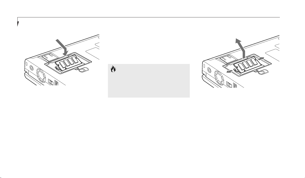
Section Four
82
To Remove a Memory Upgrade Module:
1. Perform steps 1 through 5 of To Install a
Memory Upgrade Module.
2. Pull the clips sideways away from each side
of the memory upgrade module at the same
time. (Figure 4-14.)
3. While holding the clips out, remove the
module from the slot by lifting it up and
pulling towards the rear of your notebook.
(Figure 4-14.)
10. Replace the cover by hooking the tabs
under the rear edge of the compartment
opening and tilting down until flush with
the bottom of your notebook.
11. Replace the screw.
The memory upgrade module is not something
you routinely remove from your notebook.
Once it is installed, you can leave it in place
unless you want to increase system
memory capacity.
CAUTION
Before you install or remove the memory
upgrade module, save changes and close
all files and turn power off to your notebook. (See Power Off on pages 21-22.)
Figure 4-14 Removing a Memory Upgrade Module
Figure 4-13 Installing a Memory Upgrade Module
4. Store the memory upgrade module in a
static guarded sleeve.
5.
Replace the cover by following the instructions
in steps 10 and 11 of the instructions for To
Install a Memory Upgrade Module, or install
a new memory upgrade module and then
replace the cover by following the instructions
in steps 7 through 11 of the instructions
To Install a Memory Upgrade Module.
Page 93

Four
User Installable Features
LifeBook E Series from Fujitsu
83
POINT
After installing your added memory
module, you must complete the Resetting
the Save-to-Disk Parameters procedure
in order for the Save-to-Disk mode to
operate properly on your LifeBook.
(See pages 65-66.)
CAUTION
The memory upgrade module can
be severely damaged by electro-static
discharge (ESD). Be sure you are
properly grounded when handling
and removing the module.
Checking the Computer
Recognition of New Memory Capacity
When you have changed system memory capacity by adding or removing a memory upgrade
module, be sure to check that your notebook
has recognized all of the memory. You can
check memory capacity by looking at the
Main menu of the setup utility:
1. Turn on power using the power switch.
2. Enter the setup utility by pressing the F2
key as soon as the Fujitsu logo appears
on the screen.
3. The System Memory and the Extended
Memory capacity, as detected by your notebook during the Power On Self Test (POST),
are displayed at the bottom of the Main
menu screen.
Example: A system with 32MB of memory
will display 640K System Memory, 31MB
Extended Memory.
When you have installed additional memory,
the display should change. For example for:
Total RAM System Extended
Installed Memory Memory
32 MB 640 K 31 MB
64 MB 640 K 63 MB
96 MB 640 K 95 MB
128 MB 640 K 127 MB
160 MB 640 K 159 MB
192 MB 640 K 191 MB
If the total memory displayed is not what you
believe it should be, check that your memory
upgrade module is properly installed. If it is
properly installed and the capacity is not correctly recognized, see the Troubleshooting
Section starting on page 90.
Page 94

Section Four
84
CAUTION
Follow the instructions that come with
your LANdock or Port Replicator. The
instructions and illustrations in this
manual are only to serve as a guideline.
The LANdock manual that is included
with the LANdock unit supersedes
these instructions.
LANdock unit
Leveling
Alignment Foot
Alignment Notches
Docking Connector
Undock Request Button
Docked LED
Ready to Undock LED
Docking Release Lever
Docking Alignment Pins
Figure 4-15 LANdock Front View
LANDOCK
To Hot Dock your Notebook in a
LANdock with Windows 98 Second Edition
1. To use a docking device with your notebook
they both must be on a flat surface.
2. Remove all connections from the rear
panel of your notebook. (See Figure 1-10
on page 10.)
3. Make sure that the adjustment feet are flat
against the bottom of the notebook and the
covers of the connectors, both rear panel
and right side panel, are closed.
4. Make sure that the slide cover in the rear
panel is completely open.
5. Set your notebook on the Docking Station
Leveler, making sure that the Alignment
pins on the leveler (Figures 4-15 and 4-17.)
fit into the Docking Alignment receptacles
in the bottom of your notebook.
CAUTION
Make sure you always have a battery
installed in Multi-function Bay 1 or 2
when hot-docking your notebook. Failure
to do so can severely damage the system.
Page 95

Four
User Installable Features
LifeBook E Series from Fujitsu
85
Undock Request Button
PC Card Slot
External Monitor Port
External Floppy
Disk Drive Port
Headphone
Jack
MIDI/Joystick Port
Dual USB Ports
Ethernet
(RJ-45 Jack)
Ready to Undock LED
Docked LED
DC Power Jack
Serial Port
PS/2 Mouse Port
Parallel Port
PS/2 Keyboard Port
Figure 4-16 LANdock Rear View
6. Arrange the notebook/leveler combination
to align the docking connector on the docking device body with the Docking port on
your notebook and the notches on the
leveler with the notches on the docking
device body.
7. Push together firmly.
Figure 4-17 Installing a LANdock
8. Lock in place by pulling the Docking
Release lever forward.
9.
Verify that docking is complete by checking
that the LifeBook Docked LED is illuminated.
(See Figure 4-16.)
10.
Your notebook is ready to use. (When setting
it up for the first time you must use the
power switch.)
Page 96

Section Four
86
To Hot-Undock Your Notebook
from the LANdock with Windows 98
Second Edition
1. From the Start menu click on Eject PC or
press the Undock button on the LANdock.
2. Wait for the Safe to Undock LED to illuminate, even if a message appears on your
screen saying that you may undock.
3. Your notebook will not suspend.
4. Push the lever on the side of the station
backward until the docking device connectors are completely clear of your notebook.
5. Very carefully lift your notebook clear of the
Alignment pins in the bottom.
POINT
If the notebook power switch is turned
off it is always safe to undock. You do
not have to turn on your notebook and
use the Eject PC feature.
Connecting Devices to the
LANdock or Port Replicator
Connect devices to your LANdock or Port
Replicator in exactly the same way you would
your notebook. Figure 4-16 shows the location of
LANdock ports and jacks. Figure 4-19 shows the
location of the Port Replicator ports and jacks.
Remember that on the LANdock and the Port
Replicator there are separate ports for mouse
and keyboard. You must use the correct one.
CAUTION
When your notebook is mounted in
the LANdock it is essentially a desktop
PC not a mobile notebook. DO NOT
unplug the docking device with the operating system active. You may cause a loss
of data and a system error when you
restart your notebook.
POINT
You may also put your notebook in
Suspend mode to dock the unit. It is
always safe to dock the unit with the
power switch off.
Page 97

User Installable Features
LifeBook E Series from Fujitsu
87
PORT REPLICATOR
To connect your notebook to the Port
Replicator, follow the docking instructions that
come with the Port Replicator.
Using Your Notebook
While it is Installed in the Port Replicator
There are a few differences you will notice
between using your notebook in and out of
the Port Replicator.
■
Both an external mouse and an external keyboard can be connected at the same time. Be
sure to plug them into the correct PS/2 ports.
Using Your Notebook
While it is Installed in the LANdock
There are a few differences you will notice
between using your notebook in and out
of the LANdock.
In the LANdock you have added capabilities:
■
In the Windows 98 SE Start menu there is an
Eject PC choice above the Shutdown selection. (Use the Eject PC choice to enable the
undocking of your LifeBook.)
■
Both an external mouse and an external key-
board can be connected at the same time. Be
sure to plug them into the correct PS/2 ports.
■
There is an Ethernet (RJ-45) jack for
10/100 Base-T Ethernet connections.
■
There is an additional PC Card slot.
Four
Figure 4-18 Port Replicator Front View
Port Replicator
Leveling
Alignment Foot
Alignment Notches
Docking Connector
Docking Release Lever
Docking
Alignment Pins
Page 98
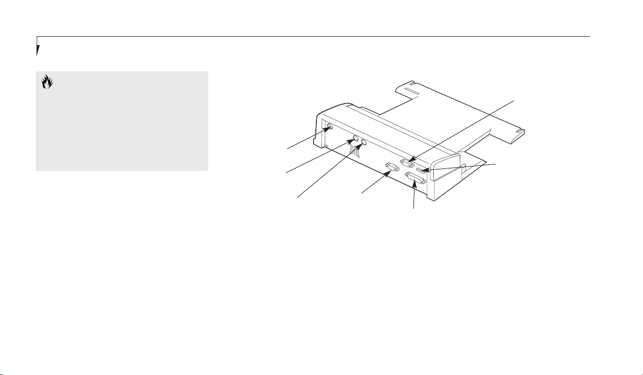
Section Four
88
CAUTION
When your notebook is mounted in the
Port Replicator it is essentially a desktop
PC not a mobile notebook. DO NOT
unplug the Port Replicator with the
operating system active. You may cause
a loss of data and a system error when
you restart your notebook.
External Monitor Port
External Floppy
Disk Drive Port
DC Power Jack
Serial Port
PS/2 Mouse Port
Parallel Port
PS/2 Keyboard Port
Figure 4-19 Port Replicator Rear View
Page 99

Troubleshooting
Section Five
Identifying the Problem. . . . . . . . . . . . 90
Specific Problems . . . . . . . . . . . . . . . 91
Power On Self Test Messages . . . . . . . . 110
Emergency DVD/CD-ROM
Tray Release . . . . . . . . . . . . . . . 113
Modem Setup and Commands . . . . . . . 113
Recovery CD-ROM . . . . . . . . . . . . . 114
Page 100

Section Five
90
SECTION FIVE
TROUBLESHOOTING
The LifeBook E Series from Fujitsu is
sturdy and subject to few problems in the field.
However, you may encounter simple setup or
operating problems that you can solve on the
spot, or problems with peripheral devices, that
you can solve by replacing the device. The information in this section helps you isolate and
resolve some of these straightforward problems,
and identify failures that require service.
IDENTIFYING THE PROBLEM
If you encounter a problem, go through the
following procedure before pursuing complex
troubleshooting:
1. Turn off your notebook using the power
switch on the right side panel.
2. Make sure the AC adapter is plugged
into your notebook and to an active AC
power source.
3. Make sure that any card installed in the
PC Card slot is seated properly. You can
also remove the card from the slot, thus
eliminating it as a possible cause of failure.
4. Make sure that any devices connected to
the external connectors are plugged
in properly. You can also disconnect such
devices, thus eliminating them as possible
causes of failure.
5. Turn on your notebook using the power
switch. Make sure it has been off at least
10 seconds before you turn it on.
6. Go through the boot sequence.
7. If the problem has not been resolved, refer
to the problem guide table, which follows, for
more detailed troubleshooting information.
(Page 91 has an index to the table.)
CAUTION
Do not return a failed notebook to
your supplier until you have talked to
a support representative.
POINT
If you keep notes about what you have
tried, your support representative may be
able to help you more quickly by giving
additional suggestions over the phone.
8. If you have tried the solutions suggested in
Specific Problems without success, contact
your support representative:
Toll free: 1-800-8FUJITSU (1-800-838-5487)
Fax: 1-901-259-5700
E-mail: 8fujitsu@fpc.fujitsu.com
Web Site: http://www.8fujitsu.com.
Before you place the call, you should have
the following information ready so that the
customer support representative can provide
you with the fastest possible solution:
■ Product name.
■ Product configuration number.
■ Product serial number.
■ Purchase date.
 Loading...