

Page 1

BIOS
SECTION
C2111/C2010
Page 2
1. BIOS setup
BIOS SETUP UTILITY
The BIOS Setup Utility is a program that sets up the operating environment for your notebook. Your
BIOS is set at the factory for normal operating conditions, therefore there is no need to set or change
the BIOS environment to operate your notebook.
The BIOS Setup Utility configures:
• Device control feature parameters, such as changing I/O addresses and boot devices.
• System Data Security feature parameters, such as passwords.
Entering the BIOS Setup Utility
To enter the BIOS Setup Utility do the following:
1. Turn on or restart your notebook.
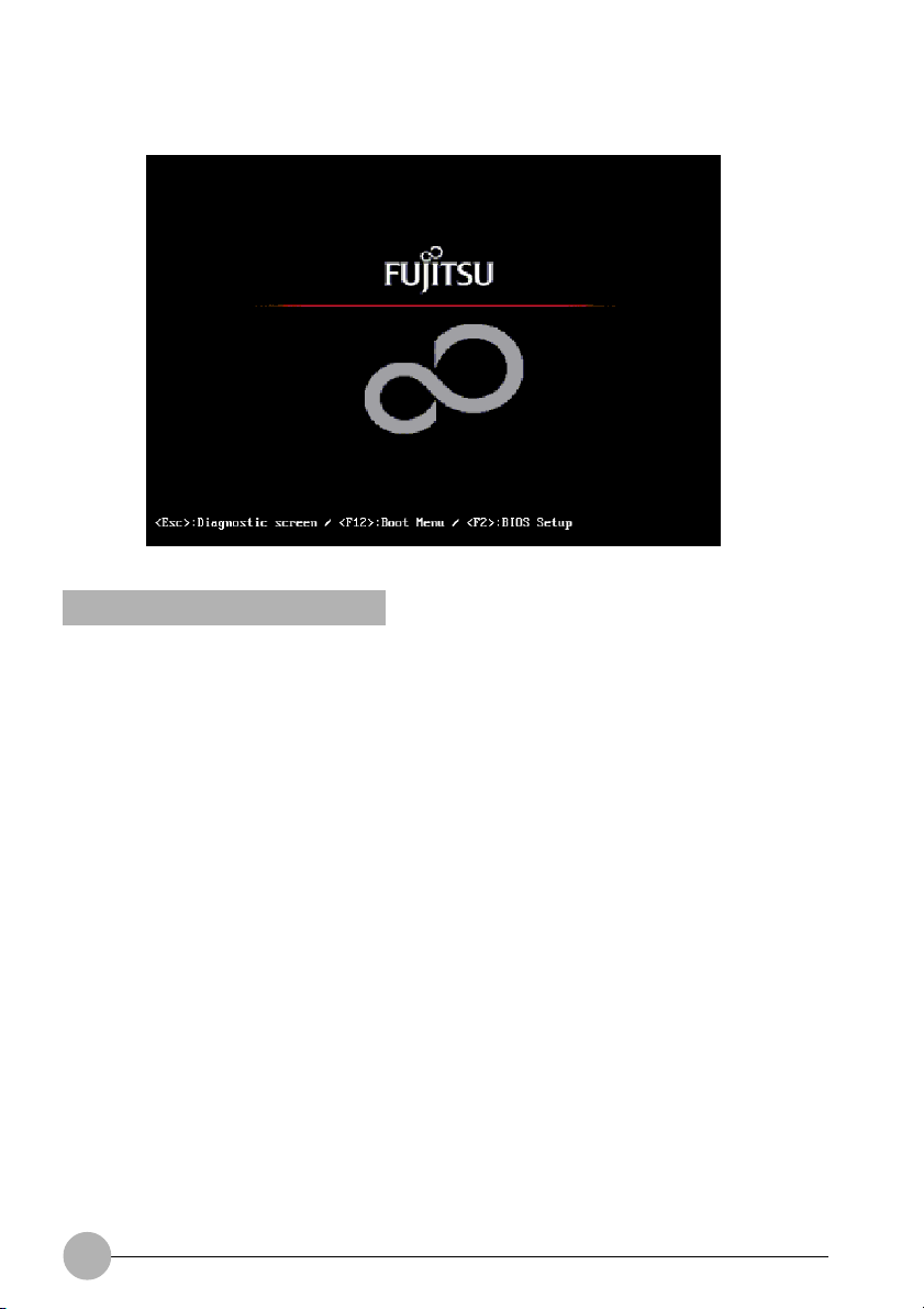
2. Press the [F2] key once the Fujitsu logo appears on the screen. This will open the main menu of
the BIOS Setup Utility with the current settings displayed.
3. Press the [RIGHT ARROW] or [LEFT ARROW] key to scroll through the other setup menus to
review or alter the current settings.
Navigating Through The Setup Utility
The BIOS setup utility consists of seven menus; Main, Advanced, Security, Power, Boot, Info and
Exit. This document explains each menu, including all submenus and setup items.
The following procedures allow you to navigate the setup utility menus:
1. To select a menu, use the cursor keys: [→] , [←].
2. To select a field within a menu or a submenu, use the cursor keys: [ ↑], [ ↓].
3. To select the different values for each field, press the [Spacebar] or [+] to change to the next
higher selec-tion and [F5] or [ - ] to go to the next lower selection.
4. To activate a submenu press the [Enter] key.
2
Page 3

5. To return to a menu from a submenu, press the [Esc] key.
6. To go to the Exit menu from any other menu, press the [Esc] key.
Critical Point
Selecting a field causes a help message about that field to be displayed on the right-hand
side of the screen.
Pressing the Enter key with the highlight on a selection that is not a submenu or auto selection
will cause a list of all options for that item to be displayed. Pressing the Enter key again will
select the highlighted choice.
7. Pressing the [F9] key resets all items in the BIOS to the default values.
8. Pressing the [F10] key saves the current configuration and exits the BIOS Setup Utility. You will
be asked to verify this selection before it is executed.
9. Pressing the [F1] key gives you a general help screen.
Entering the Setup Utility After a Configuration Change or System Failure
If there has been a change in the system configuration that does not match the parameter settings
stored in your BIOS memory , or there is a f ailure in the system, the system beeps and/or displa ys an
error message after the Power On Self Test (POST). If the failure is not too sev ere, it will give y ou the
opportunity to modify the settings of the setup utility, as described in the following steps:
1. When you turn on or restart the computer there is a beep and/or the following message appears
on the screen:
Error message - please run SETUP program Press <F1> key to continue,
<F2> to run SETUP
2. If an error message is displayed on the screen, and you want to continue with the boot process
and start the operating system anyway, press the [F1] key.
Critical Point
If your notebook emits a series of beeps that sounds like a code and the display is blank,
please refer to the Troubleshooting Section. The Troubleshooting Section includes a list of
error messages and their meanings.
If your data security settings require it, you may be ask ed for a pass word bef ore the operating
system will be loaded.
3. If an error message is displayed on the screen, and y ou want to enter the setup utility, press the
[F2] key.
4. When the setup utility starts with a fault present, the system displays the following message:
Warning!
Error message
[Continue]
5. Press any key to enter the setup utility. The system will then display the Main Menu with current
parameters values.
3
Page 4
MAIN MENU
SETTING STANDARD SYSTEM PARAMETERS
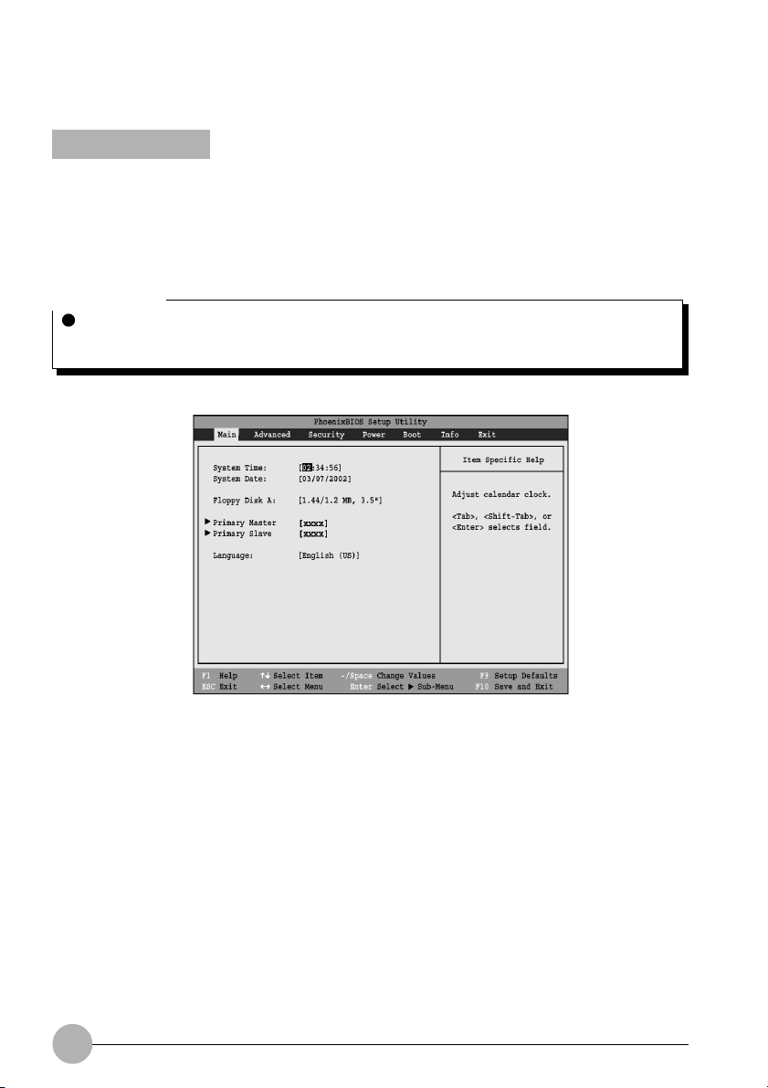
The Main Menu allows you to set or view the current system parameters. Follow the instructions for
Navigating Through The Setup Utility to make any changes.
The following tables show the names of the menu fields for the Main menu and its submenus, all of
the options for each field, the default settings and a description of the field’ s function and any special
information needed to help understand the field’s use.
Critical Point
System Time and System Date can also be set from your oper ating system without using the
setup utility. Use the calendar and time icon on your Windows Control panel or type time or
date from the MS-DOS prompt.
Figure 1. Main Menu
4
Page 5

Table 1: Fields, Options and Defaults for the Main Menu
* Note that the parameters listed below may differ, as determined by your system configuration.
Menu Field
System Time:
System Date:
Floppy Disk A:
Primary Master:
Primary Slave:
Language:
Options
—
—
• Disabled
• 1.44/1.2 MB 3.5"
Selects Primary
Master submenu
• Selects Primary
Master submenu
• English (US)
• Japanese (JP)
Default
—
—
[1.44/1.2 MB 3.5"]
The product #
of the Hard Drive
The product
number of the
CD-ROM
[English (US)]
Description
Sets and displays the current time.
Time is in a 24 hour format of
hours:minutes:seconds with 2 digits
for each. (HH:MM:SS). Example:
16:45:57. You may change each
segment of the time separately.
Move between the segments with
the [Tab] key and/or [Shift] + [Tab]
keys.
Sets and displays the current date.
Date is in a month/day/year numeric
format with 2 digits each for month
and day and 4 digits for year. (MM/
DD/YYYY) for example: 03/20/1998.
You may change each segment of
the date separately. Move between
the segments with the [Tab] key and/
or [Shift] + [Tab] keys.
Enables or disables a floppy disk.
Display the type of device on this
ATA/ATAPI interface, if there is one.
Pressing the Enter key selects the
Primary Master submenu allowing
additional device configuration
options for this interface.
Display the type of device on this
ATA/ATAPI interface, if there is one.
Pressing the Enter key selects the
Secondary Master submenu
allowing additional device
configuration options for this
interface.
The default setting differs between
the US/European and the Japanese
model. Selects the display language
for the BIOS.
5
Page 6
Primary Master Submenu of the Main Menu
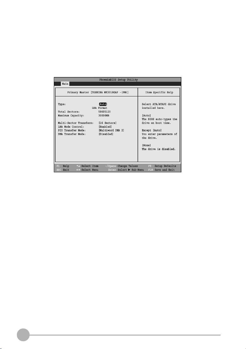
The Primary Master submenu identifies what ATA devices are installed.
* Note that actual hard drive label shown ma y vary. Depending on the drive type, information such as
cylinders, heads and sectors may also be displayed.
Figure 2. Primary Master Submenu
6
Page 7

Table 2: Fields, Options and Defaults for the Primary Master Submenu of the Main Menu
Menu Field
Type:
CHS Format (Cylinders, Heads, Sectors)
Cylinders:
Heads:
Sectors:
Maximum
Capacity:
Options
• Auto
• None
• CD-ROM
• Hard Disk
• A number
between 0
and 65,535
• A number
between 1
and 16
• A number
between 0
and 63
• Display only
Default
[Auto]
—
—
—
––
Description
Selects the ATA/ATAPI device type.
Select Auto to have the type
automatically identified by the BIOS
at POST. If None is selected, all of
the following Set-up items do not
appear. Select CD-ROM if a CDROM drive is installed at this
connection. If Hard Disk is selected,
you must specify the number of
Cylinders, Heads, and Sectors for
the drive.
This item appears only when Hard
Disk is selected. When Hard Disk is
selected, you can change the value.
This field is changed by
incrementing (pressing the
[Spacebar]) or by typing in the
number.
This item appears only when Hard
Disk is selected. When Hard Disk is
selected, you can change the value.
This field is changed by
incrementing (pressing the
[Spacebar]) or by typing in the
number.
This item appears only when Hard
Disk is selected. When Hard Disk is
selected, you can change the value.
This field is changed by
incrementing (pressing the
[Spacebar]) or by typing in the
number.
Displays the maximum capacity of
the drive calculated from the
parameters of the hard disk when
Auto is selected and the type is
identified as hard disk, or User is
selected.
7
Page 8

Table 2: Fields, Options and Defaults for the Primary Master Submenu of the Main Menu
Menu Field
Multi-Sector
Transfers:
LBA Mode
Control:
Transfer
Mode:
Ultra DMA
Mode:
Options
• Disabled
• 2 Sectors
• 4 Sectors
• 8 Sectors
• 16 Sectors
• Disabled
• Enabled
• Standard
• Fast PIO 1
• Fast PIO 2
• Fast PIO 3
• Fast PIO 4
• Multiword
DMA 1
• Multiword
DMA 2
• Disabled
• Mode 0
• Mode 1
• Mode 2
• Mode 3
• Mode 4
• Mode 5
Default
[16 Sectors]
[Enabled]
[Multiword
DMA 2]
[Mode 5]
Description
This option cannot be changed
when Auto is selected. Specify the
number of sectors per block for
multiple sector transfer .
Enables or disables logical Block
Addressing in place of Cylinder,
Head, Sector addressing. This
option cannot be changed when
Auto is selected.
Selects the method for moving data
to/from the drive. Autotype the drive
to select the optimum transfer mode.
This option cannot be changed
when Auto is selected. Multi-word
DMA is automatically set to mode 1
for Fast PIO 1, Fast PIO 2, Fast
PIO 3, and set to mode 2 for Fast
PIO 4 / DMA.
Selects the method for moving data
to/from the drive. Autotype the drive
to select the optimum transfer mode.
This option cannot be changed
when Auto is selected.
CAUTION
In A bootable CD-ROM may have a floppy disk format or a hard drive format. When the
bootable CD-ROM is used, the drive allocations change automatically without changing the
BIOS setup. If a floppy disk for-mat CD-ROM is used, the CD-ROM becomes Drive A. The
CD-ROM will only take Drive C: (hard drive format) if the internal hard drive is not present or
is disabled. The bootable CD-ROM can ne ver use a C: designation if a f ormatted internal hard
drive is present, since the C: designator is always reserved for the internal hard drive.The
boot sequence ignores the new drive designations, but your application software will use the
new designations.
Be careful of the operating environment when booting from a CD-ROM or y ou ma y o v erwrite
files by mistake.
8
Page 9
Secondary Master Submenu of the Main Menu
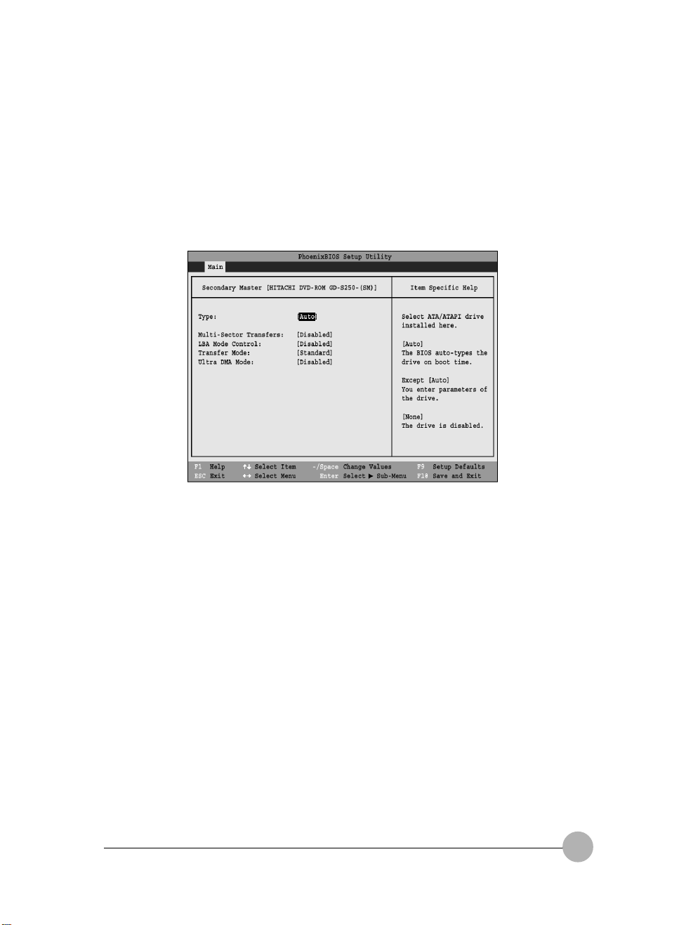
The Secondary Master submenu is for the internal CD-ROM drive. The drive type is displa yed on this
menu as well as the Main menu. Your notebook auto-senses the characteristics of the internal CDROM Drive installed.
You will not need to modify these settings, they are displayed for your reference.
Note that actual drive labels shown may vary.
Figure 3. Secondary Master Submenu
BS_C2111/2010(01-21) 2/07/02, 10:51 AM9
9
Page 10

Table 3: Fields, Options and Defaults for the Secondary Master Submenu of the Main Menu
Menu Field
Type:
Multi-Sector
Transfers:
LBA Mode
Control:
Transfer
Mode:
Ultra DMA
Mode:
Options
• Auto
• None
• CD-ROM
• Hard Disk
• Disabled
• 2 Sectors
• 4 Sectors
• 8 Sectors
• 16 Sectors
• Disabled
• Enabled
• Standard
• Fast PIO 1
• Fast PIO 2
• Fast PIO 3
• Fast PIO 4
• Multiword
DMA 1
• Multiword
DMA 2
• Disabled
• Mode 0
• Mode 1
• Mode 2
• Mode 3
• Mode 4
• Mode 5
Default
[Auto]
[Disabled]
[Disabled]
[Standard]
[Disabled]
Description
Selects the ATA/ATAPI device type.
Select Auto to have the type
automatically identified by the BIOS
at POST. If None is selected, all of
the following Set-up items do not
appear. Select CD-ROM or Hard
Disk for appropriate drive type
installed at this connection.
This option cannot be changed
when Auto is selected. Specify the
number of sectors per block for
multiple sector transfer.
Enables or disables Logical Block
Addressing in place of Cylinder,
Head, Sector addressing. This
option cannot be changed when
Auto is selected.
Selects the method for moving data
to/from the drive. Autotype the drive
to select the optimum transfer mode.
This option cannot be changed
when Auto is selected. Multi-word
DMA is automatically set to mode 1
for Fast PIO 1, Fast PIO 2, Fast
PIO 3, and set to mode 2 for Fast
PIO 4/DMA.
Selects the method for moving data
to/from the drive. Autotype the drive
to select the optimum transfer mode.
This option cannot be changed
when Auto is selected.
Exiting from Main Menu
When you have finished setting the parameters on this menu, you can either exit from the setup
utility, or move to another menu. If you wish to exit from the setup utility, press the [Esc] key or use
the cursor keys to go to the Exit menu. If you wish to move to another menu, use the cursor keys.
10
BS_C2111/2010(01-21) 2/07/02, 10:51 AM10
Page 11
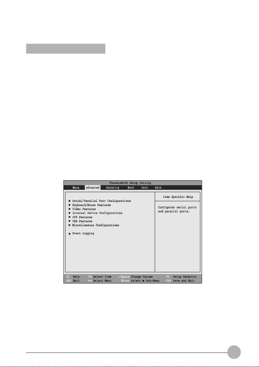
ADVANCED MENU
SETTING DEVICE FEATURE CONTROLS
The Advanced Menu allows you to:
• Set the I/O addresses for the ports.
• Set the communication mode for the parallel and infrared ports.
• Set the features of the keyboard/mouse.
• Select between the display panel and an external CRT display.
• Configure IDE devices in your system.
• Configure CPU features.
• Configure USB features.
• Configure DMI Event Logging.
• View DMI Event Logging
Follow the instructions for Navigating Through the Setup Utility to make any changes.
The following tables show the names of the menu fields f or the Advanced Men u and its submenus, all
of the options for each field, the default settings and a description of the field’s function and any
special information needed to help understand the field’s use.
Note that not all fields appear in all configurations; the fields that appear are dependent upon the
system CPU.
Figure 4. Advanced Menu
11
Page 12

Table 4: Fields, Options and Defaults for the Advanced Menu
Menu Field
Serial/Parallel
Port Configurations
Keyboard/Mouse
Features
Video Features
Internal Device
Configurations
CPU Features
USB Features
Miscellaneous
Configurations
Event Logging
Description
When selected, opens the Serial/Parallel Port Configurations submenu
which allows the user to modify settings for the infrared and parallel ports.
When selected, opens the Keyboard/Mouse Features submenu, which
enables and disables the power-on state for [Numlock].
When selected, opens the Video Features submenu, which allows setting of
the display parameters, including routing of video signals to different
displays.
When selected, opens the Internal Device Configurations submenu, which
allows enabling or disabling the IDE Controllers.
When selected, opens the CPU Features submenu, which allows enabling or
disabling the SpeedStepTM Technology feature for optimal battery life.
When selected, opens the USB Features submenu, which allows enabling or
disabling of Legacy Floppy Emulation.
When selected, opens the Miscellaneous Configurations submenu, which
allows you to configure the power button.
When selected, opens the event logging submenu.
12
Page 13
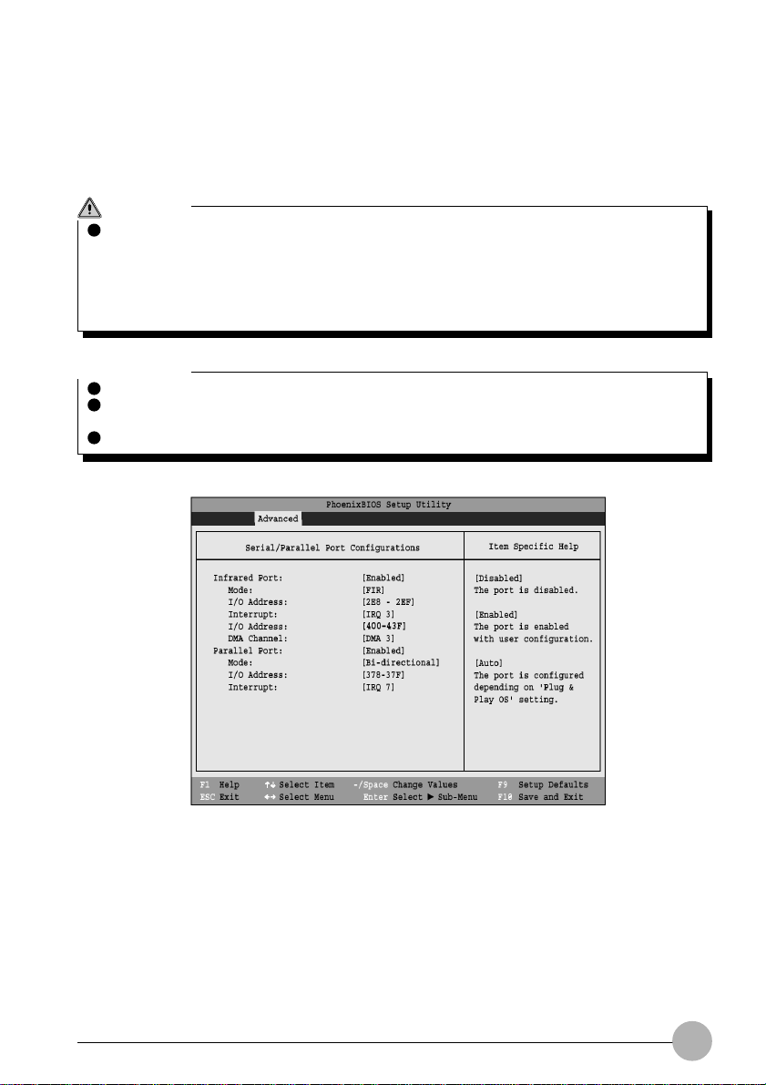
Serial/Parallel Port Configuration Submenu of the Advanced Menu
The Serial/Parallel Port Configuration submenu provides the ability to set the I/O addresses and
interrupt levels for the serial, infrared, and parallel ports of your notebook.
CAUTION
I/O addresses, DMA channels, and Interrupt levels can be entered in various ways, including
via the BIOS setup utility, the control software for the I/O device, or the hardware. If any two
ports or devices, serial or parallel, have the same I/O address assigned, your notebook will
not function normally. Please keep a record of original settings before making any changes in
the event that a restoration is required. See your hardware and software documentation as
well as the setup utility to determine settings, limitations, etc.
Critical Point
To prevent IRQ and address conflicts, avoid changing the default settings.
The BIOS will warn you of a resource conflict by placing a yello w asterisk next to each de vice
that is in conflict.
All I/O addresses in Table 5 are in hexadecimal.
Figure 5. Serial/Parallel Port Configuration Submenu
13
Page 14

Table 5: Fields, Options and Defaults for the Port Configuration Submenu of the
Advanced Menu
Menu Field
Infrared Port:
Mode:
I/O Address
Interrupt:
I/O address:
DMA Channel:
Parallel Port:
Mode:
I/O address:
Interrupt:
Options
• Disabled
• Enabled
• Auto
• IrDA
• FIR
• 3F8 - 3FF
• 2F8 - 2FF
• 3E8 - 3EF
• 2E8 - 2EF
• IRQ 3
• IRQ 4
• IRQ 10
• IRQ 11
• 400 - 43F
• 400 - 4BF
• 500 - 53F
• 580 - 5BF
• DMA 1
• DMA 3
• Disabled
• Enabled
• Auto
• Output Only
• Bi-directional
• ECP
• 378 - 37F
• 278 - 27F
• 3BC - 3BF
• IRQ 5
• IRQ 7
Default
[Enabled]
[FIR]
[2E8 - 2EF]
[IRQ 3]
[400 - 43F]
[DMA 3]
[Enabled]
[Bi-directional]
[378 - 37F]
[IRQ 7]
Description
When Disabled, the infrared port is
disabled; when Enabled, the infrared
port is enabled. When Auto is
selected, the Plug & Play operating
system configures the port.
Select the mode for the infrard port:
Infrared or Fast Infrared.
Allows user to set the infrared port
I/O address when the infrared port is
Enabled.
Allows user to set the infrared port
interrupt when the infrared port is
Enabled.
Allows user to set the infrared port
I/O address when the infrared port is
Enabled.
Allows user to set the infrared port
DMA Channel when the infrared port
is Enabled.
Configures the parallel port using
either no configuration (Disabled), a
user defined configuration (Enabled),
or by allowing the BIOS or OS to
choose the configuration (Auto).
When the parallel port is enabled this
option is available allowing the user
to set the mode for the parallel port.
Bi-directional allows two-way transfer
of information between your
notebook and a connected parallel
device. Output Only (Half Duplex)
allows information to be transferred in
only one direction, from your
notebook to the printer or similar
device. ECP Mode allows
communication with the ECP class of
parallel I/O devices.
Allows user to set the parallel port
base I/O address when the parallel
port is Enabled.
Allows user to set the parallel port
interrupt when the parallel port is
Enabled.
14
Page 15
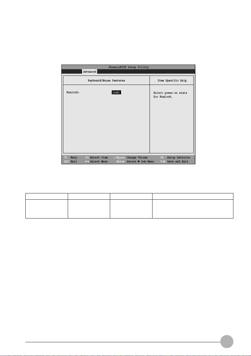
Keyboard/Mouse Features Submenu of the Advanced Menu
The Keyboard/Mouse Features submenu is for setting the power-on state for the Numlock key.
Figure 6. Keyboard/Mouse Features Submenu
Table 6: Fields, Options and Defaults for the Keyboard/Mouse Submenu of the
Advanced Menu
Menu Field
Numlock:
Options
• On
• Off
Default
[Off]
Description
Sets the NumLock function state
when the computer completes
booting.
15
Page 16
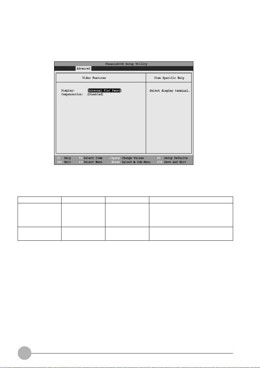
Video Features Submenu of the Advanced Menu
The Video Features Submenu is for choosing the display.
Figure 7. Video Features Submenu
Table 7: Fields, Options and Defaults for the Video Features Submenu of the
Advanced Menu
Menu Field
Display:
Compensation:
Options
• Internal
Flat Panel
•External
•Simultaneous
• Disbled
• Enabled
Default
[Internal
Flat Panel]
[Disbled]
Description
Selects where the video signal will
be routed.
Enables or disables video
compensation.
16
Page 17
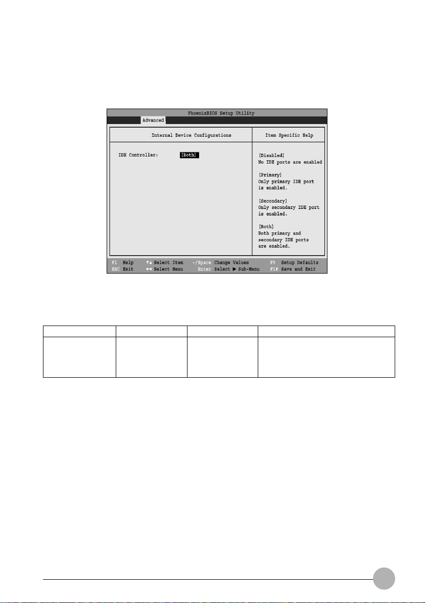
Internal Device Configurations Submenu of the Advanced Menu
The Internal Device Configurations submenu allows the user to enable or disable IDE and Wireless
LAN.
Figure 8. Internal Device Configurations Submenu
Table 8: Fields, Options and Defaults for the Internal Device Configurations Submenu of the
Menu Field
IDE Controller:
Advanced Menu
Options
• Disabled
• Primary
• Secondary
• Both
Default
[Both]
Description
Enables or disables IDE controllers.
17
Page 18
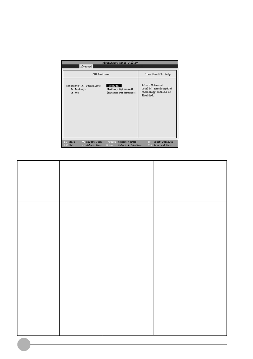
CPU Features Submenu of the Advanced Menu
The CPU Features Submenu configures the system processor . Note that this submenu only appears
in certain configurations, based upon the system CPU.
Figure 9. CPU Features Submenu
Menu Field
SpeedStep
Technology
On Battery
On AC
(TM)
Options
• Enabled
• Disabled
• Maximum
• Performance
• Battery
Optimized
• Automatic
• Maximum
• Performance
• Battery
Optimized
• Automatic
Default
[Enabled]
[Battery Optimized]
[Maximum Performance]
Description
When Disabled is selected,
CPU speed is fixed to battery
optimized speed. When Enabled
is selected, CPU speed and
battery use can be selected
from On Battery and On AC.
When Maximum Performance is
selected, CPU speed is
maximized. When Battery
Optimized is selected, CPU
power requirements are
optimized for battery operation.
When Maximum Battery is
selected, CPU speed is
optimized for battery operation.
When Automatic is selected, the
CPU speed is determined by
the power source used.
When Maximum Performance is
selected, CPU speed is
maximized. When Battery
Optimized is selected, CPU
power requirements are
optimized for battery operation.
When Maximum Battery is
selected, CPU speed is
optimized for battery operation.
When Automatic is selected, the
CPU speed is determined by
the power source used.
18
Page 19
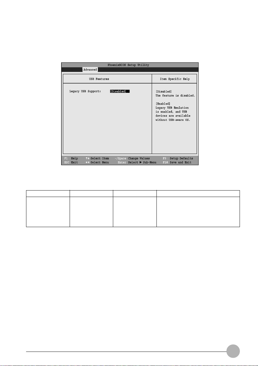
USB Features Submenu of the Advanced Menu
The USB Features Submenu configures the system for use with a USB floppy drive.
Figure 10. USB Features Submenu
T able 10: Fields, Options and Defaults f or the USB Features Submenu of the Ad v anced Menu
Menu Field
Legacy USB
Support:
Options
• Disabled
• Enabled
Default
[Disabled]
Description
When Enabled is selected, Legacy
USB devices are available without a
USB-aware OS. When Disabled is
selected, Legacy USB Emulation is
disabled.
19
Page 20
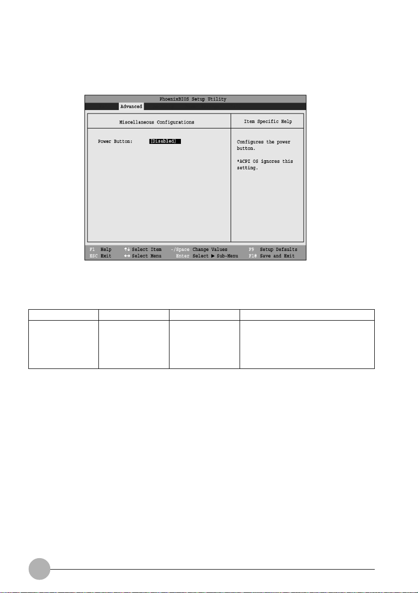
Miscellaneous Configurations Submenu of the Advanced Menu
The Miscellaneous Configurations Submenu configures the power button.
Figure 11. Miscellaneous Configurations Submenu
Table 11: Fields, Options and Defaults for the Miscellaneous Configuration
Menu Field
Power Button:
20
Options
• Disabled
• Power Off
Default
[Disabled]
Description
When Disabled is selected, the
power button does not control power.
When Power Off is selected,
pressing the power button shuts off
power to the system.
Page 21
Event Logging Submenu of the Advanced Menu
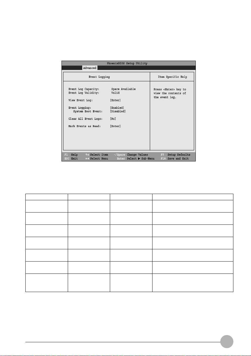
The Event Logging Submenu is for setting up the logs for DMI event logging.
Figure 12. Event Logging Submenu
Table 12: Fields, Options and Defaults for the Event Logging Submenu of the
Menu Field
Event Log
Capacity:
Event Log Validity:
View Event Log:
Event Logging:
System Boot
Event:
Clear All Event
Logs:
Mark Events as
Read:
Advanced Menu
Options
• Disabled
• Enabled
• Enter
• Disabled
• Enabled
• Disabled
• Enabled
• No
• Y es
• Enter
Default
Space Available
Valid
[Enter]
[Enabled]
[Disabled]
[No]
[Enter]
Description
Display only
Display only
Allows you to view content of event
log.
Turns event logging on and off for all
DMI events.
Turns event logging on and off for
DMI system boot events.
When set to [Yes] all event logs will
be cleared at next boot.
Allows you to make all events
currently in the event log as having
been read.
21
Page 22
SECURITY MENU
SETTING THE SECURITY FEATURES
The Security menu allows you to set up the data security features of your notebook to fit y our operating
needs and to view the current data security configuration. Follow the instructions for Navigating
Through the Setup Utility to make any changes.
The tables show the names of the menu fields for the Security menu and its submenus, all of the
options for each field, the default settings and a description of the field's function and any special
information needed to help understand the field's use. The def ault condition is no passw ords required
and no write protection.
Critical Point
If you set a password, write it down and keep it in a saf e place . If you forget the password you
will have to contact your support representative to regain access to your secured functions
and data.
CAUTION
Entering a password incorrectly 3 times in a row will cause the keyboard and mouse to be
locked out and the warning [System Disabled] to be displayed. If this happens restart the
computer by turning the power off and on with the power s witch and use the correct password
on reboot.
If you make an error when re-entering the passw ord a warning will be displayed on the screen.
To try again press the Enter key and retype the password. Press the Esc key to abort the
password setting pro-cess.
If Password On Resume is Enabled and Password On Boot is Disabled you will not have to
type your password upon resuming the system from the Suspend or Save-to-Disk modes.
Password On Resume will work only if Password On Boot is enabled.
Boot sector protection must be set to [Normal] to install or upgrade an operating system.
22
Page 23
Menu Field
Supervisor
Password is:
User Passw ord is:
Set Supervisor
Password
Set User
Password
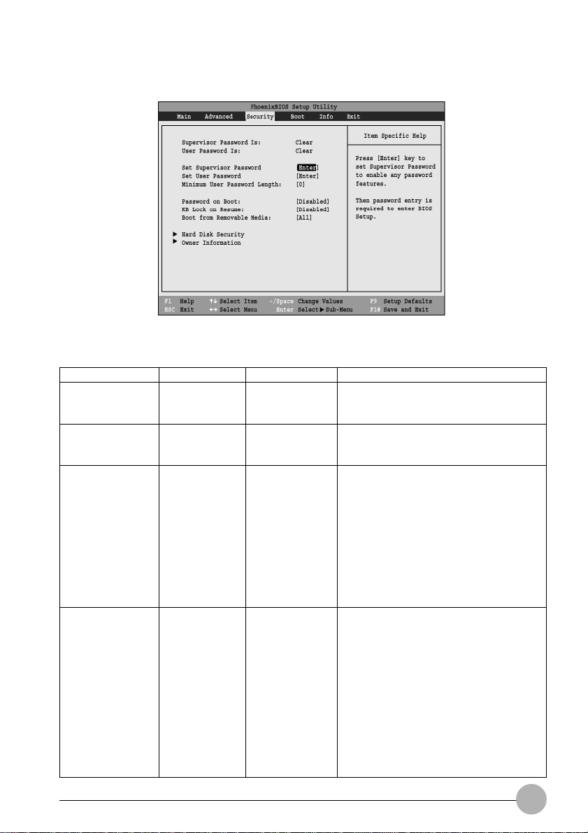
Figure 13. Security Menu
Table 13: Fields, Options and Defaults for the Security Menu
Options
––
––
––
––
Default
Clear
Clear
[Enter]
[Enter]
Description
A display-only field. Set is displa yed when
the system supervisor password is set and
Clear when it is not.
A display-only field. Set is displa y ed
when the general user password is set,
and Clear when it is not.
Sets, changes or cancels the Supervisor
Passw ord. The Supervisor P assword may
be up to seven characters long and must
include only letters or numbers (no
symbols). P ass w ords are NOT casesensitive. To cancel a password press the
Enter key instead of entering characters in
the Enter New Pass word field and in the
Re-enter New Pass word field. When a
Supervisor Password is set it must be
used to access the BIOS setup utility .
This field can only be accessed if the
Supervisor Password is set. This field sets,
changes or cancels the User Password.
The User Password ma y be up to seven
characters long and must include only
letters or numbers (no symbols).
Passw ords are NO T case-sensitiv e . To
cancel a password press the Enter key
instead of entering characters in the Enter
New Passw ord field and in the Re-enter
New Passw ord field. When a User
Passw ord is set it must be used to access
the BIOS setup utility .
23
Page 24

Table 13: Fields, Options and Defaults for the Security Menu
Menu Field
Minimum User
Password Length:
Password on
Boot:
KB Lock on
Resume:
Boot from
Removable Media:
Hard Disk
Security:
Owner
Information:
Options
––
• Disabled
• First Boot
• Every Boot
• Disabled
• Enabled
• All
• Supervisor only
––
––
Default
[0]
[Disabled]
[Disabled]
[All]
––
––
Description
When set to Disabled, no password
is required. When set to First Boot, a
password (User or Supervisor) is
required after the Power On Self
Test (POST) before the operating
system will be read from a disk. If
Every Boot is set, a password (User
or Supervisor) is required after the
Power On Self Test (POST) every
time the system is booted (before
the operating system is read from
the disk).
When set to Enabled, the PS/2
mouse and keyboard inputs are
locked out upon Resume from
Suspend or Save to Disk mode until
you enter the password. When set to
Disabled no password is required. If
no Supervisor Password is set, this
feature is not available and no
password is required.
Enable password allows supervisor
access only.
Configures hard disk security
features.
Set Owner information.
24
Page 25
Hard Disk Security Submenu of the Security Menu
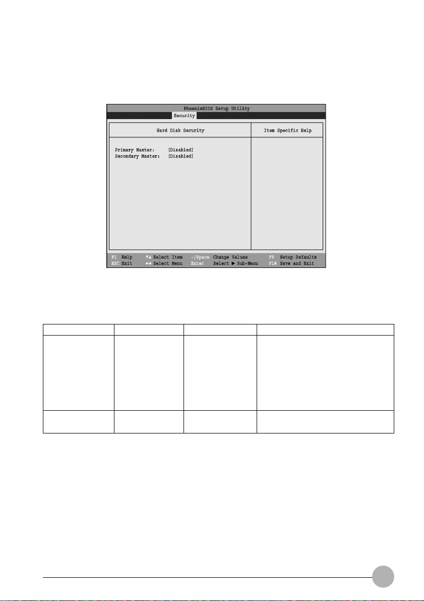
The Hard Disk Security submenu is for configuring hard disk security features.
Figure 14. Hard Disk Security Submenu
Table 14: Fields, Options and Defaults for the Hard Disk Security Submenu of the
Menu Field
Primary Master:
Secondary
Master:
Security Menu
Options
• Disabled
• Enabled
• Disabled
• Enabled
Default
[Disabled]
[Disabled]
Description
Disabled: No password protection.
Enabled: The hard disk is locked
with the password. Data in the
locked disk cannot be read on any
systems other than the original
system on which it is locked or
system that have the identical
password setting.
25
Page 26
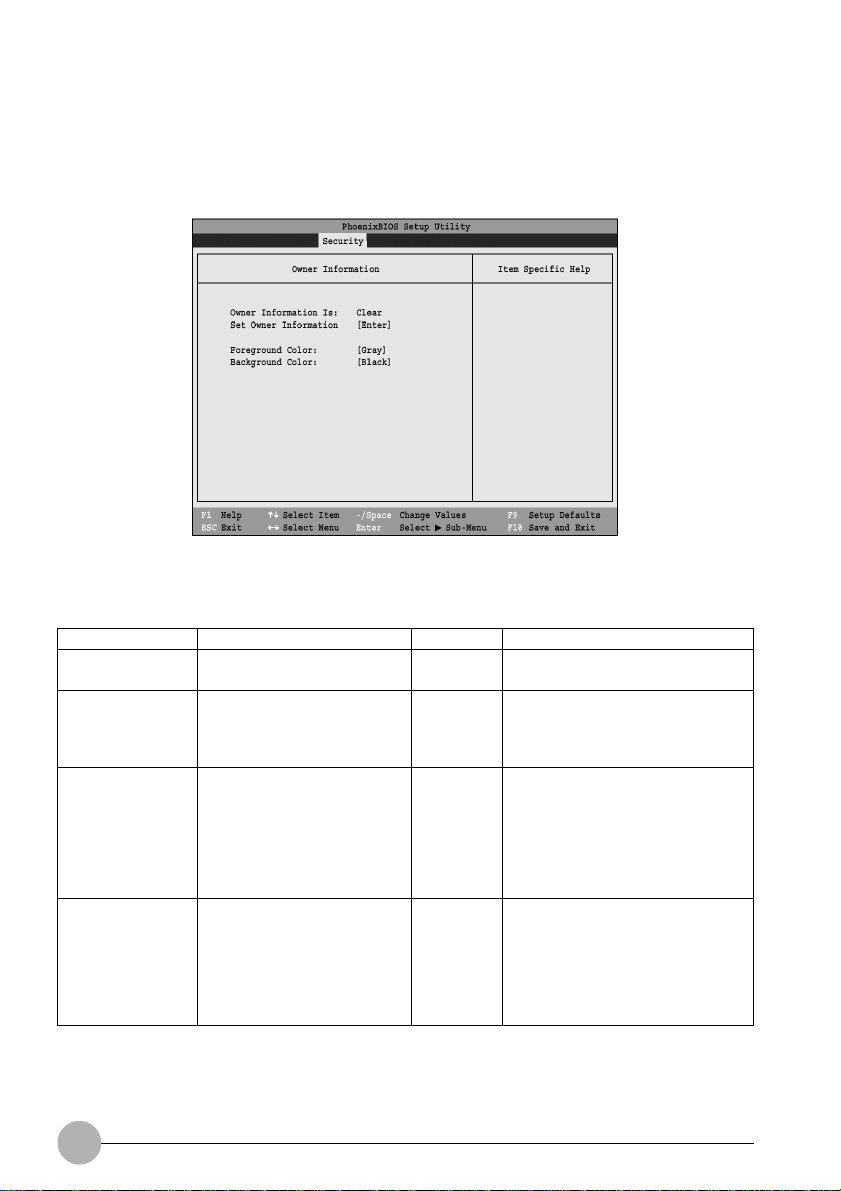
Owner Information Submenu of the Security Menu
The Owner Information submenu is for setting owner information.
Note: The submenu can be modified only if a Supervisor’s Password has been set previously.
Figure 15. Owner Information Submenu
Table 15: Fields, Options and Defaults for the Owner Information Submenu of the
Security Menu
Menu Field
Owner
Options
––
Default
Clear
Description
Display only.
Information Is:
Set Owner
Information:
Foreground Color:
Background Color:
––
• Black • Gray
• Blue • Light Blue
• Green • Light Green
• Cyan • Light Cyan
• Red • Light Red
• Magenta • Light Magenta
• Brown • Yellow
• White • Bright White
• Black • Gray
• Blue • Light Blue
• Green • Light Green
• Cyan • Light Cyan
• Red • Light Red
• Magenta • Light Magenta
• Brown • Yellow
• White • Bright White
[Enter]
[Gray]
[Black]
Field to write owner information
(i.e. name).
Select a color for the foreground.
Select a color for the background.
Exiting from Security
When you have finished setting the boot parameters with the Security, you can either exit from the
setup utility or move to another menu. If you wish to e xit from the setup utility press the [Esc] key to go
to the Exit menu. If you wish to move to another menu, use the cursor keys.
26
Page 27
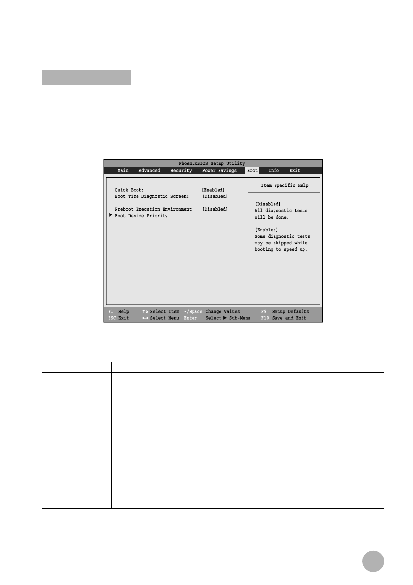
BOOT MENU
SELECTING THE OPERATING SYSTEM SOURCE
The Boot Menu is used to select the order in which the BIOS searches sources for the operating
system. Follow the instructions for Navigating Through the Setup Utility to make any changes.
The following tables show the names of the men u fields for the Boot men u and its submenu, all of the
options for each field, the default settings and a description of the field’s function and any special
information needed to help understand the field’s use.
Figure 16. Boot Menu
Table 16: Fields, Options and Defaults for the Boot Menu
Menu Field
QuickBoot Mode:
Boot-time
Diagnostic
Screen:
Preboot Execution
Environment
Boot Device
Priority
Options
• Disabled
• Enabled
• Disabled
• Enabled
• Disabled
• Enabled
• Selects the Boot
Device Priority
submeny
Default
[Enabled]
[Disabled]
[Disabled]
—
Description
When [Disabled] is selected, all
diagnostic tests are performed when
the system is booted up. If [Enabled]
is set, some of the tests are skipped
in order to speed up the booting
process.
Turns on and off display of test
results instead of Fujitsu logo screen
during Power On Self Test.
Turns on and off boot from network
server options.
This menu allows setting up the
source for the operating system.
27
Page 28
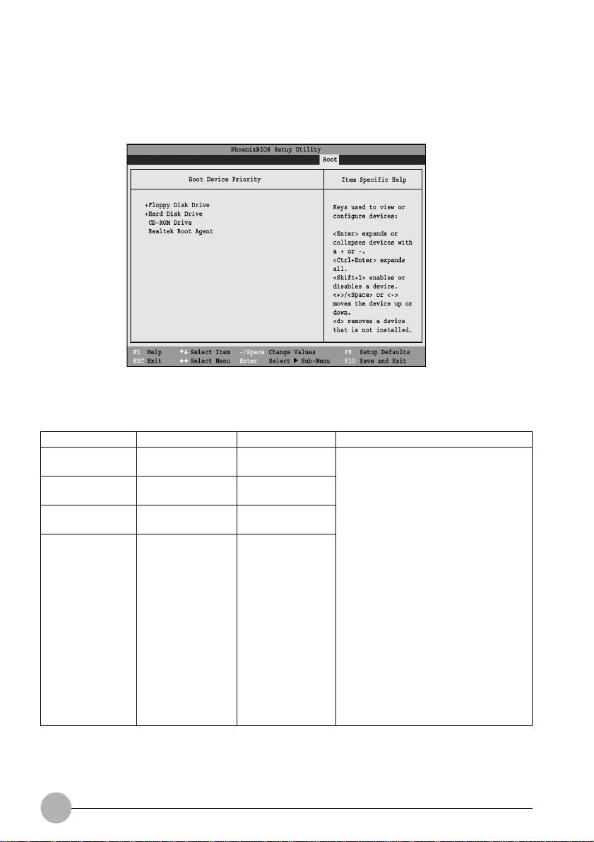
The Boot Device Priority Submenu of the Boot Menu
The Boot Device Priority Submenu is for setting the order of checking of sources for the operating
system.
Figure 17. Boot Device Priority Submenu
Table 17: Fields, Options and Defaults for the Boot Device Priority Submenu of the Boot
Menu Field
+Floppy Disk
Drive
+Hard Disk Drive
CD-ROM Drive
Realtek Boot
Agent
Menu
Options
—
—
—
—
Default
—
—
—
—
Description
The boot selections determine the
order in which the BIOS searches for
the operating system during a startup
sequence. To view all devices related
to a source, press [Enter]; to view all
devices related to all sources, press
[Ctrl] + [Enter]. To change the order,
highlight one source by using the [up]
or [down] cursor keys and then press
the [+] or [-] key to change the order
number for that source. [Shift] + [1]
enables a device. Pressing [d]
removes from the list a device that is
not installed. Be sure to save your
changed order when you exit the
BIOS setup utility.
NOTE: Be aware that if you use the
CD-ROM drive as the first boot
device, certain files may be
overwritten, depending upon your
operating environment.
Exiting from Boot Menu
When you have finished setting the boot parameters with the Boot men u, you can either e xit from the
setup utility or move to another menu. If you wish to exit from the setup utility, press the [Esc] key to
go to the Exit menu. If you wish to move to another menu, use the cursor keys.
28
Page 29
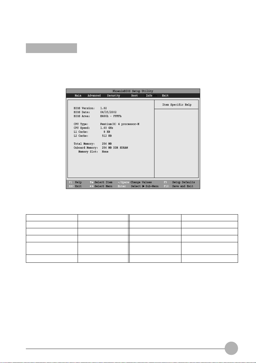
INFO MENU
DISPLAYS BASIC SYSTEM INFORMATION
The Info menu is a display only screen that pro vides the configuration inf ormation for your notebook.
The following table shows the names of the men u fields for the Info men u and the information displayed
in those fields. These fields are for information purposes only, and cannot be modified by the user.
Figure 18. Info Menu
Table 18: Fields, Options and Defaults for the Info Menu
Menu Field
BIOS Version:
BIOS Date:
BIOS Area:
CPU T ype:
CPU Speed:
Default
1.02
04/25/2002
E400h-FFFFh
Pentium(R) 4
processor-M
1.60 GHz
Menu Field
L1 Cache:
L2 Cache:
Total Memory:
Onboard Memory:
Memory Slot:
Default
8 KB
512 KB
256 MB
256 MB DDR SDRAM
None
29
Page 30
EXIT MENU
LEAVING THE SETUP UTILITY
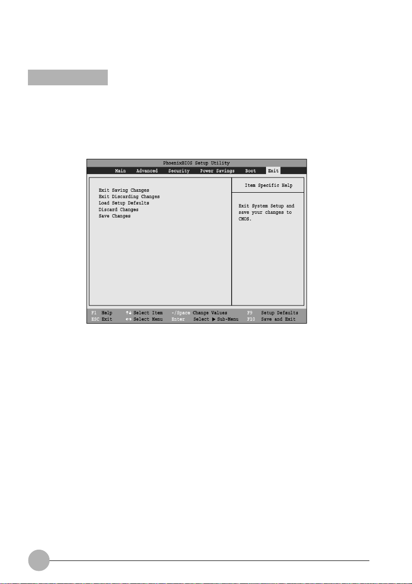
The Exit Menu is used to leave the setup utility. Follow the instructions for Navigating Through the
Setup Utility to make any changes.
The following table sho ws the names of the menu fields for the Exit menu, the default settings and a
description of the field’s function and any special information needed to help understand the field’s
use.
Figure 19. Exit Menu
30
Page 31

Menu Field
Exit Saving
Changes
Exit Discarding
Changes
Load Setup
Defaults
Discard Changes
Save Changes
Table 19: Fields, Options and Defaults for the Exit Menu
Keyboard
Shortcut
Press F10 key
—
Press F9 key
—
—
Description
Exit Saving Changes and Exit will store all the entries
on every menu of the setup utility to the BIOS memory
and then exit the setup utility. A confirmation message
Save Configuration changes and exit now?
[Yes] [No] will be displayed.
Selecting Exit Discarding Changes and Exit will exit the
setup utility with out writing to the BIOS memory. A setup
warning message Configuration has not been
saved! Save before exiting? [Yes] [No] will
be displayed when your settings have changed. When the
BIOS recognizes the Exit Discarding Changes selection it
will load the operating system and begin operation.
Selecting Load Setup Defaults will load the factory preset
default values f or all menu fields, then displa y the message
Load default configuration now? [Yes] [No].
When confirmed the setup utility will return to the Exit Menu.
To return to another menu follow the directions in the
Navigating Through the Setup Utility Section.
Selecting Discard Changes will load the previous values
in BIOS memory for all menu fields. The message Load
previous configuration now? [Yes] [No] will be
displayed. When confirmed the setup utility will return to
the Exit menu. To retur n to another menu, follow the
directions in the Navigating Through the Setup Utility
Section.
Selecting Save Changes will cause the new settings in all
menus to be written to the BIOS memory. The message
Save configuration changes now? [Yes] [No] will be
displayed. When confirmed, the setup utility will return to
the Exit menu. To retur n to another menu, follow the
directions in the Navigating Through the Setup Utility
section.
31
 Loading...