

Page 1

IP-9610
Hardware User’s Guide
Page 2

(This page is intentionally left blank)
Page 3
USING IP-9610 SAFELY
Handling of This Manual
The manual contains important information regarding the safe use of IP-9610. Read it thoroughly
before operating this device. Make sure that users of the device read and understand thoroughly all
safety precautions contained in the manual. Keep this manual in a safe and convenient location for
quick reference.
Fujitsu makes every effort to prevent users and bystanders from injury and to prevent property damage.
To ensure no harm to you and bystanders, and to prevent damage to the device itself, be sure to use this
equipment in accordance with instructions
The following notice is for USA users only.
IP-9610 has been tested and found to comply with the limits for a Class A digital device, pursuant to
Part 15 of the FCC Rules. These limits are designed to provide reasonable protection against harmful
interference when the equipment is operated in a commercial environment. This equipment generates,
uses, and can radiate radio frequency energy and, if not installed and used in accordance with the
instruction manual, may cause harmful interference to radio communications. Operation of this
equipment in a residential area is likely to cause harmful interference in which case the user will be
required to correct the interference at his own expense.
The following notice is for Canada users only.
This Class A digital apparatus meets all requirements of the Canadian Interference-Causing
Equipment Regulations.
The following notice is for EU (European Union) users only.
This is Class A product of Electromagnetic Interference (EMI) standard. In a domestic environment
this product may cause radio interference in which case the user may be required to make adequate
measures.
This manual includes technology controlled under the Foreign Exchange and Foreign Trade Control
Law of Japan. The manual or a portion thereof must not be exported (or re-exported) without
authorization from the appropriate governmental authorities in accordance with the above law.
IP-9610 is designed and manufactured for use in standard applications such as office work, personal
devices, and household appliances. The product is not intended for special uses (such as
nuclear-reactor control in atomic energy facilities, aeronautic and space systems, air traffic control,
operation control in mass transit systems, medical devices for life support, and missile firing controls in
weapons facilities) where particularly high reliability requirements exist, where the pertinent levels of
safety are not guaranteed, or where a failure or operational error could threaten a life or cause physical
injury (hereafter referred to as "mission-critical" use). Customers considering use of this product for
mission-critical applications must have safety-assurance measures in place beforehand. Moreover,
they are requested to consult our sales representative before embarking on such specialized use.
Copying of and disassembly, decompilation and other forms of reverse engineering of any program
included with this device is prohibited.
Windows, Internet Explorer are registered trademarks or trademarks of Microsoft Corporation in the
United States and/or other countries.
in the manual.
IP-9610
i
Page 4

IMPORTANT NOTE TO USERS
READ THE ENTIRE MANUAL CAREFULLY BEFORE USING THIS PRODUCT.
INCORRECT USE OF THE PRODUCT MAY RESULT IN INJURY OR DAMAGE TO
USERS, BYSTANDERS OR PROPERTY.
While FUJITSU has sought to ensure the accuracy of all information in this manual, FUJITSU
assumes no liability to any party for any damage caused by any error or omission contained in this
manual, its updates or supplements, whether such errors or omissions result from negligence, accident,
or any other cause. In addition, FUJITSU assumes no liability with respect to the application or use of
any product or system in accordance with descriptions or instructions contained herein; including any
liability for incidental or consequential damages arising therefrom.
FUJITSU DISCLAIMS ALL WARRANTIES REGARDING THE INFORMATION
CONTAINED HEREIN, WHETHER EXPRESSED, IMPLIED, OR STATUTORY.
FUJITSU reserves the right to make changes to any products described herein without further notice
and without obligation.
No part of this manual shall be reproduced in any way or form without the permission of Fujitsu Limited.
©
All Rights Reserved. Copyright
FUJITSU LIMITED 2011
IP-9610
ii
Page 5

PREFACE
Thank you for purchasing the IP-9610(H264/AVC CODEC).
IP-9610 are the video transmission unit with the H.264 encoding technology.
This manual explains how to use hardware for IP-9610.
This manual is intended for system designers and system managers who use IP-9610. Readers are
assumed to have a basic knowledge of networks and video distribution.
November 2011 1st Edition
Product operating environment
• Designed for use in real-time audio/video transmission systems and in the transmission system of
monitoring systems, IP-9610 is intended for indoor use.
Note:
The contents of this manual are subject to change without notice.
iii
IP-9610
Page 6

ORGANIZATION AND CONTENTS OF THIS MANUAL
The manual consists of five chapters, an appendix, a glossary and an index.
Read Chapters 1 and 2 first for information on installing and connecting the device. Read Chapter 3 for
operating instructions, and Chapter 4 and subsequent chapters can be read as required.
Chapter 1 Preparations
This chapter describes the checks that are required before the start of IP-9610 operation.
Chapter 2 Installation and Connection
This chapter describes conditions for IP-9610 installation and explains how to connect it to peripheral the
devices.
Chapter 3 Operating Instructions
This chapter explains how to power on/off, set up and operate the device.
Chapter 4 Connection Cable Specifications
This chapter contains a classification of how work is implemented, cable connection system diagrams
and cable connector details.
Chapter 5 Troubleshooting
This chapter describes actions to be taken if the device does not operate normally or if an alarm LED
turns on.
Appendix
The appendix contains views of the device and its basic specifications. Installation work and on-site
adjustment preparations are also covered in this section.
Glossary
The glossary defines the technical terms used in this manual.
Index
The index lists keywords and corresponding pages on which the words appear, so necessary items can be
looked up immediately.
IP-9610
iv
Page 7
WARNING INDICATIONS
This manual uses warning indications to warn of conditions in order to prevent serious injury and
property damage. Warning indications consist of warning markings of specific levels and warning
messages. The warning markings are shown below along with their definitions.
!
WARNING indicates a situation that could lead to serious injury
or loss of life if procedures are not followed correctly.
CAUTION indicates a situation that could lead to minor or
CAUTION
Warning indications within text
Warning markings are followed by warning messages. Every warning marking is centered on a line.
Left and right indents are set for warning messages to differentiate them from ordinary text.
Furthermore, the lines immediately before and after warning indications are left blank.
moderate injury and/or damage to the device itself if procedures
are not followed correctly.
(Example)
Possibility of electric shock, fire and damage to the device
Always observe the precautions given below.
This indicates a hazardous situation that could lead to electric shock, fire or
damage to the device.
• Always connect the power cord to a power receptacle for a standard
two-prong plug with ground.
• Connect the device to the power receptacle with a capacity of 1A or
more. When using a power extension cable, be sure that the total
power consumption of all devices connected to the cable does not
exceed the rated capacity of the cable. If a power receptacle with a
low capacity or capacity below the rated value is used, the power
receptacle, extension cable or power distribution wiring may overheat
and start a fire.
Important warning indications are summarized below in “Safety Precautions.”
v
IP-9610
Page 8

SAFETY PRECAUTIONS
List of important warnings
The table below contains a list of important warning indications.
Indicates a situation that could lead to serious injury or loss of life if procedures
are not followed correctly.
Work type Warning
Normal use Possibility of electric shock and fire
If an excessive heat, smoke, an abnormal odor or an unusual noise is coming from the
device, immediately set its power switch to OFF and remove the power cord plug from
the power receptacle. Then, contact a Fujitsu Service Center.
This indicates a hazardous situation that could lead to fire and electric shock.
Possibility of electric shock and fire
If foreign matter (e.g., water, bits of metal, fluid) gets inside the device, immediately set
its power switch to OFF and remove the power cord plug from the power receptacle.
Then, contact a Fujitsu Service Center.
This indicates a hazardous situation that could lead to fire and electric shock.
Possibility of electric shock and fire
If the device has been dropped or otherwise damaged, immediately set its power switch
to OFF and remove the power cord plug from the power receptacle. Then, contact a
Fujitsu Service Center.
This indicates a hazardous situation that could lead to electric shock.
Possibility of electric shock and fire
To keep foreign matter out, ensure that drink containers and metal objects are not placed
on or near the device.
The presence of foreign matter such as water inside the device creates a hazardous
situation that could lead to electric shock.
Possibility of electric shock and fire
Ensure that no liquid is splashed on the device, making it wet.
The presence of foreign matter such as water inside the device creates a hazardous
situation that could lead to fire and electric shock.
Possibility of electric shock and fire
Ensure that the power cord does not become damaged, and avoid tampering with it.
If the power cord has a heavy object is placed on it, pulled at, bent, or becomes entangled, it
could be damaged as a result. Also, the power cord could be damaged if subjected to heat,
creating a hazardous situation that could lead to fire and electric shock.
Possibility of electric shock
Because this device contains a hazardous voltage section, never open the cover.
Only a service engineer must open the cover.
This warning indicates a hazardous situation that could lead to electric shock.
IP-9610
vi
Page 9

Work type Warning
Installation
Possibility of electric shock and fire
Do not install the device in the following places because using it there may cause a fire or
electric shock:
• Extremely dusty or dirty place
• Wet or humid location
• Hot location, such as a place where the device is exposed to direct sunlight or is
near heating equipment
• Near products (e.g., speakers) that generate a strong magnetic field
• Location where the temperature is too hot or cold
• In an environment with sharp temperature fluctuations
• Area with poor ventilation
• Near a fire
Possibility of electric shock, fire, and damage to the device
Always observe the precautions given below.
This indicates a hazardous situation that could lead to electric shock, fire and damage to
the device.
• Always connect the power plug to a power receptacle for a standard two-prong plug
with ground.
• Connect the device to a power receptacle with a capacity of 1 A or more. When
using a power extension cable, be sure that the total current consumption of all
devices connected to the cable does not exceed the rated capacity of the cable. If a
power receptacle with a low capacity or capacity below the rated value is used, the
power receptacle, extension cable or power wiring may overheat and start a fire.
vii
IP-9610
Page 10

Work type Warning
Installation
and
relocation
Clean
Possibility of serious injury and damage to the device
Do not install the device in places where it is exposed to shock and strong vibrations, on
an incline or in unstable locations.
This indicates a hazardous situation that could lead to serious injury or damage to the
device.
Possibility of serious injury and damage to the device
When relocating the device, observe the following precautions to protect against serious
injury and damage to the device:
• Set the power switch to OFF, and disconnect all connected cables. Take care to
avoid getting your feet entangled in the cables.
• To prevent serious personal injury when moving the device, take special care to pay
attention to your surroundings.
Possibility of fire, serious injury and damage to the device
When cleaning the device, observe the following precautions to protect against fire,
serious injury and damage to the device:
• When cleaning the device, please do not use cleaning spray that is including
combustible material. Also, please do not use it around the device.
• When cleaning the device, please wipe off with the cloth squeezing water (or
neutral detergent thinned by water).
• When wiping off, please be careful not to put water into the device from switches
or the spaces.
IP-9610
viii
Page 11
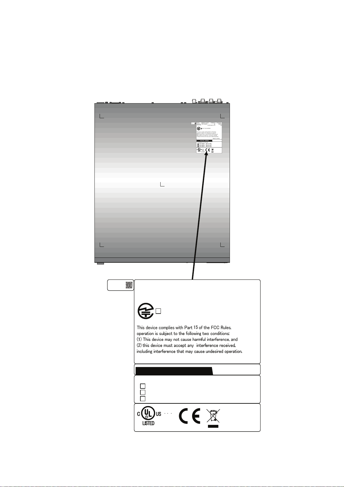
LABEL
The warning label sho wn below is affixed to the device.
・ Never remove the label.
・ Be sure to check the label at the bottom of this device before coming to the power supply.
・ The following label is intended for users of the device s.
01A
00001
11-11
MODEL
PART NO.
FC40761A1
H264/AVC CODEC
TA23793-B10X
認証番号
T
D11-0165001
FUJITSU LIMITED
Installed Option Part Number
TA23793-B20X
TA22168-B70X
TA22168-B70X
(96CODES-A0)
(96ACMDL-A0)
(96ACMDL-A0)
1.70A-0.71A
1φ
0.170kVA-0.171kVA
MADE IN JAPAN
100V-240V~
50/60Hz
7kg
I T E
1K91
E136004
IP-9610
ix
Page 12

PRODUCT HANDLING PRECAUTIONS
Maintenance
WARNING
Do not try to repair the device yourself. Contact a Fujitsu Service Center.
CAUTION
Read this manual thoroughly before attempting to operate the device.
If you have any questions, contact a Fujitsu Service Center.
If a problem occurs, contact a Fujitsu Service Center.
The Fujitsu Service Center will ask you to describe the problem, the lamp display status of
alarm LEDs and other details. Check the system for this information.
Connectable devices
Only devices that conform to the device interface specifications (see Appendix 2.3, "Device
Specifications") can be connected. Otherwise, if incompatible devices are connected, the result
may be personal injury and property damage.
Disposal
To dispose of the device, contact a Fujitsu Service Center, or request a specialist to take care its
disposal.
Modification and restoration
Do not use any device that has been modified or rebuilt with refurbished used parts. Doing so
may result in personal injury and property damage.
IP-9610
x
Page 13

CONTENTS
USING IP-9610 SAFELY .................................................................................i
PREFACE ..................................................................................................... iii
ORGANIZATION AND CONTENTS OF THIS MANUAL............................... iv
WARNING INDICATIONS..............................................................................v
SAFETY PRECAUTIONS .............................................................................vi
LABEL ........................................................................................................... ix
PRODUCT HANDLING PRECAUTIONS .......................................................x
Chapter 1 Preparations.......................................................................... 1
1.1 Main Features ........................................................................................ 3
1.2 Components........................................................................................... 5
1.3 Basic Application Examples ................................................................... 6
1.4 Part Names ............................................................................................ 7
Chapter 2 Installation and Connection............................................... 11
2.1 Installation Conditions .......................................................................... 13
2.1.1 Environment conditions............................................................. 13
2.1.2 Installation environment............................................................. 13
2.1.3 Air flow into and out from the device ......................................... 16
2.1.4 Open space required around the device.................................... 17
2.2 Power Supply System Connections................................................... 18
2.2.1 Connection to ground................................................................ 18
2.2.2 Connection to power source...................................................... 19
2.3 Connection to External Sync(REF) ...................................................... 22
2.4 Connection to DVB-ASI Device............................................................ 23
2.4.1 Connection to DVB-ASI Input Device........................................ 23
2.4.2 Connection to DVB-ASI Output Device ..................................... 24
2.5 Connection to RS-232C/RS-422 Device............................................ 25
2.6 Connection to Network ......................................................................... 26
2.7 Connection to Voice Communication (Intercom) .................................. 27
2.8 Optional Board Slot .............................................................................. 28
Chapter 3 Operation Instructions ....................................................... 29
3.1 Power ON/OFF .................................................................................... 31
3.1.1 Powering on .............................................................................. 31
3.1.2 Powering off .............................................................................. 31
3.2 Device Settings and Operation ............................................................ 32
3.3 Device Settings and Operation (Front Panel)....................................... 33
3.4 Special Use of Cancel Key................................................................... 34
Chapter 4 Cable Specifications........................................................... 35
4.1 Installation Preparations....................................................................... 37
4.2 Cable and Connector Details ............................................................... 38
I
IP-9610
Page 14

Chapter 5 Troubleshooting..................................................................45
5.1 Help Information ...................................................................................47
5.2 Alarm LED Lamp Is On .........................................................................49
5.3 Maintenance .........................................................................................50
5.3.1 Maintenance space ....................................................................50
5.3.2 Change of maintenance parts (Maintenance only)..................... 51
Appendix..................................................................................................53
A.1 Appearance ..........................................................................................55
A.2 Basic Specifications ..............................................................................57
A.2.1 External specifications ...............................................................57
A.2.2 Environment specifications ........................................................57
A.2.3 Function specifications...............................................................58
A.3 Preparations for Installation Work ......................................................... 62
A.3.1 Scope of installation work ..........................................................62
A.3.2 Unpacking and device check .....................................................62
A.3.3 Installation conditions.................................................................62
A.3.4 Connecting external cables........................................................62
A.4 Preparations for On-site Turn-up........................................................63
Glossary and Index .................................................................................67
Glossary.......................................................................................................69
Index ............................................................................................................72
CE Conformity Information...........................................................................74
IP-9610
II
Page 15

CHAPTER 1
Chapter 1 Preparations
This chapter describes the checks that are required before the start of IP-9610
operation.
1.1 Main Features ············································································ 3
1.2 Components··············································································· 5
1.3 Basic Application Examples ······················································· 6
1.4 Part Names ················································································ 7
PREPARATIONS
Page 16

(This page is intentionally left blank)
Page 17
Chapter 1 Preparations
1.1 Main Features
1.1
IP-9610 are the video transmission unit with the H.264 encoding technology.
Supports H.264 4:2:2 10 bit 1080p video, delivering high quality video encoding.
1U main equipment can hold two codec boards, supporting up to two channels of video encoding.
Scalable equipment enables configurations matching your operation scenarios to make it possible by
combining SDI Input/Output Board and option licenses.
Equipment can be operated from the Web GUI, front panel, or SNMP, providing high operability.
By combining the base equipment and hardware options, you can initially assemble the required
functions in the IP-9610. You can flexibly configure the IP-9610 by selecting the SDI input board to
have the equipment function as an encoder, or selecting the SDI output board to have the equipment
function as a decoder. Also, you can add the Audio Board to use the 16 channel audio function.
And, to operate this equipment, you need to purchase a software license key and activate it.
For details, see the software manuals
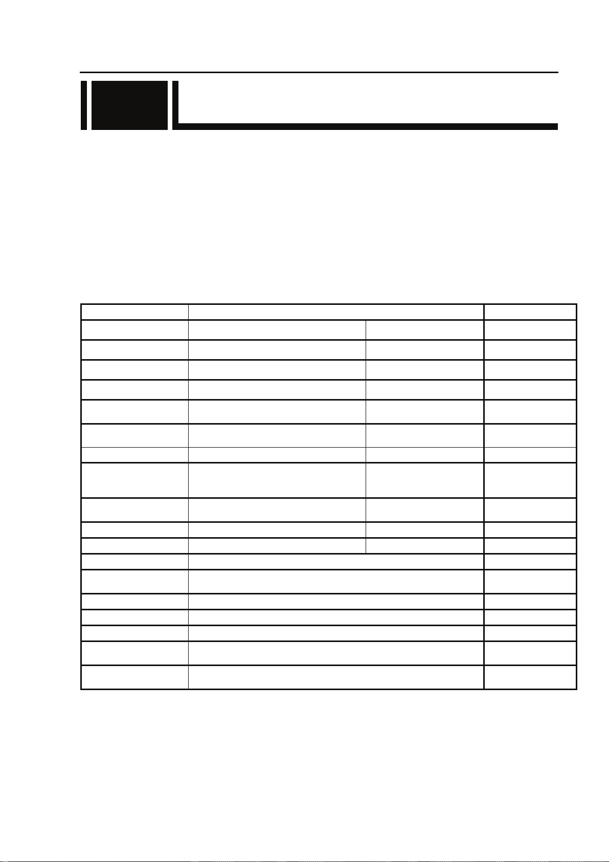
Main Features
Item Specifications
Video input HD-SDI / SD-SDI 2ch(max) [BNC]
Video output HD-SDI / SD-SDI 8ch(max) [BNC]
Audio input HD-SDI embedded 16ch(max) [BNC], 8 stereo pairs
Audio output HD-SDI embedded 16ch(max) [BNC], 8 stereo pairs
Reference clock input
Reference clock output
Voice input/output Analog balanced 600Ω 1ch [RJ25]
Network LAN 3ch
Data input/output RS-232C 2ch
SD CARD slot SD CARD 1 For maintenance use
USB USB Interface 1 For maintenance use Future Support
Installation conditions Indoor: On a desk, mounted in a rack
Dimensions
Cooling system Forced air cooling
Power supply 100-240VAC
Weight Maximum 7kg
Power consumption
Temperature
Humidity
Analog Composite 75Ω or
Component 75Ω
Analog Composite 75Ω or
Component 75Ω
W: 425 H: 42 D: 350 (mm)
W: 425 H: 46 D: 520.3 (mm) Note: Including optional board, etc
170VA or less (100V AC)
171VA or less (240V AC)
0 to 50°C
20 to 90%RH (No condensing)
1ch [BNC]
1ch [BNC]
[RJ45],
10BASE-T/100BASE-TX
/1000BASE-T
[D-sub9-pin]
male connector
Note: Excluding protrusions
Remarks
Located at option slot
#1~#4
Located at option slot
#1~#4
Located at option slot
#1~#4
Located at option slot
#1~#4
Future Support
3
IP-9610
Page 18

Chapter 1 Preparations
Hardware option Maximum
Description
installation
SDI input board
4
SDI output board
Codec board (*1) 2
Audio board (*2) 2
Installed according to the number of SDI inputs/outputs.
Combining two SDI input boards or two SDI output boards
enables support for dual-link SDI.
A codec board is always installed in the base equipment. Installing
one additional board enables the following operation modes (*3):
Encoder x 2
Decoder x 2
Encoder x 1 and Decoder x 1
Decoder x 1 and Encoder x 1
With a Codec Board, this board enables support of the 16 channel
s audio (stereo pairs of 8 channels) function.
*1 The codec board has an 8 channel audio function.
*2 If two codec boards are installed, an audio board must be added to each of these codec boards
(two audio boards must be added).
*3 For details on combinations of operation modes and the AV input-output interfaces, refer
Appendix 5 AV Interface Settings the IP-9610 Software User's Guide.
It is necessary to install a software license (encoder license or decoder license) by operation
mode. For example, operation mode [Encoderx2] requires two encoder licenses.
IP-9610
4
Page 19
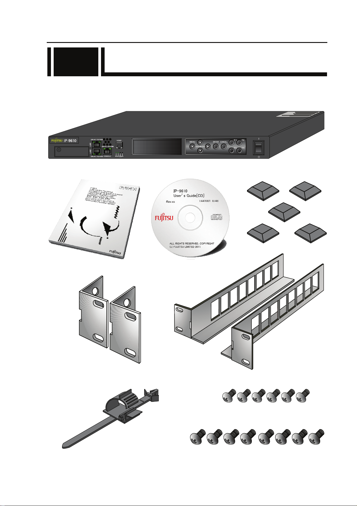
1.2 Components
1.2
The IP-9610 product package consists of the following components.
Attachments for all series consist of same contents.
・ IP-9610: 1 pc (cables separate order)
・ Safety manual: 1 pc ・ User’s Guide: 1 pc ・ Feet: 5 pcs
・ Mounting kit on 19” rack: 2 pcs
・ Holder of power supply cable: 1 pc ・ Pan screw (M4): 6 pcs
(19” rack - Mounting kit)
・ Pan screw (M5): 8 pcs
(19” rack - Mounting kit)
Chapter 1 Preparations
5
IP-9610
Page 20
Chapter 1 Preparations
1.3 Basic Application Examples
1.3
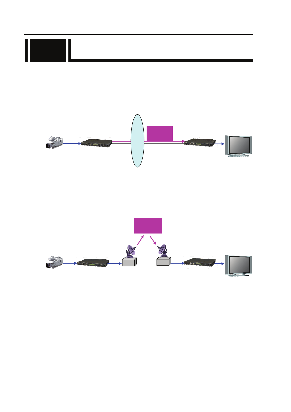
Examples (system configuration) of use of IP-9610 are shown below.
The basic configuration is for video transmission via point-to-point connections.
With this configuration, the camera is connected to the encoder, and video data is transmitted to the
decoder over the Internet, and then output to the monitor.
Camera
SDI
IP-9610 encoder
Internet
distribution
Live
IP-9610 decoder
SDI
Monitor
System configuration example: Broadcast content transmission or live coverage
By using the DVB-ASI interface included with this equippment as standard, the equippment can also
be used for video transmission via satellite news gathering (SNG) or field pickup equippment (FPE).
Live
distribution
SDI
IP-9610 encoder
IP-9610 decoder
Camera
DVB-ASI
DVB-ASI
SDI
System configuration Example: SNG
Monitor
IP-9610
6
Page 21
Chapter 1 Preparations
1.4 Part Names
1.4
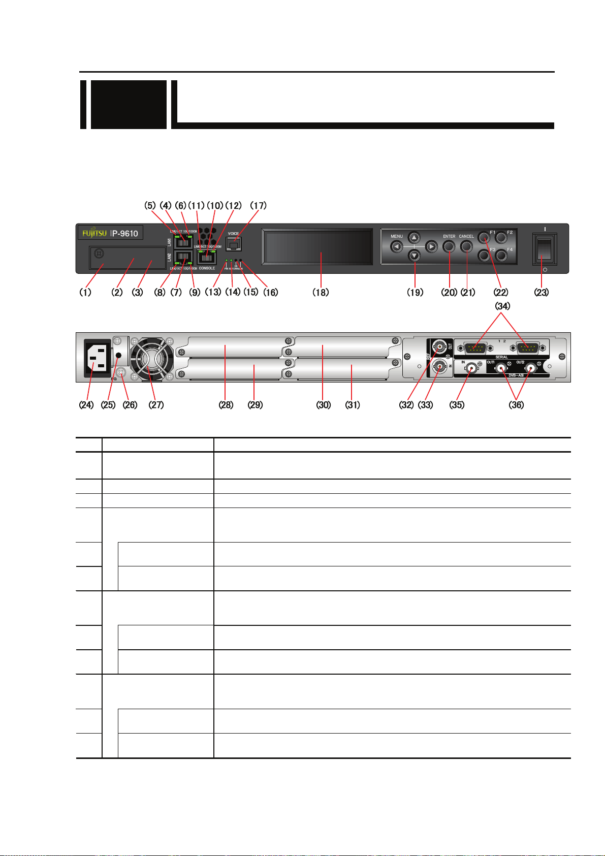
This section gives the name and describes the function of individual parts of IP-9610.
The diagrams below show the layout of parts on the outside of the device, and the table below lists
the name and describes the function of individual parts. Numbers in the diagrams correspond to
numbers in the table.
Figure Front panel
Figure Rear panel
1
3
2
4
Part names
No. Name Description
SD CARD slot
(1)
Maintenance port
(2)
USB port
(3)
LAN port #1
(4)
(LAN1)
(5)
(6)
LAN port #2
(7)
(LAN2)
(8)
(9)
CONSOLE port
(10)
(CONSOLE)
(11)
(12)
Status LED
(LINK/ACT)
Speed LED
(100/1000M)
Status LED
(LINK/ACT)
Speed LED
(100/1000M)
Status LED
(LINK/ACT)
Speed LED
(100/1000M)
For maintenance purpose. Not for customer. (Future Support)
Covered with screw.
For maintenance purpose. Not for customer..
For maintenance purpose. Not for customer. (Future Support)
Ethernet 10BASE-T/100BASE-TX /1000BASE-T communication port.
See Section 2.6, “Connection to a Network,” for an explanation on using this port.
See Section 4.2, “Cable and Connector Details,” for cable connection information.
Indicates the status of LAN port.
For more information, see Table 5.3, “Details of LED Indications,” in Section 5.2.
Indicates the speed of LAN port.
For more information, see Table 5.3, “Details of LED Indications,” in Section 5.2.
Ethernet 10BASE-T/100BASE-TX /1000BASE-T communication port
See Section 2.6, “Connection to a Network,” for an explanation on using this port.
See Section 4.2, “Cable and Connector Details,” for cable connection information.
Indicates the status of console port.
For more information, see Table 5.3, “Details of LED Indications,” in Section 5.2.
Indicates the speed of console port.
For more information, see Table 5.3, “Details of LED Indications,” in Section 5.2.
.
7
IP-9610
Page 22

Chapter 1 Preparations
No. Names Description
Power LED (PWR)
(13)
Status LED
(14)
(RDY)
AV input status LED
(15)
(INDWN)
Alarm LED
(16)
(ALM)
Voice input/output
(17)
(VOICE)
(18) VFD panel
Direction key
(19)
(△▽Y Z)
Enter key
(20)
(ENTER)
Cancel key
(21)
(CANCEL)
Function key
(22)
(F1~F4)
Power button
(23)
Power inlet connector
(24)
(INPUT 100-240VAC)
AC cord clamp hole
(25)
FG terminal
(26)
(27)
(28)
(29)
(30)
(31)
(32)
)
(FG
FAN
Optional slot 1
Optional slot 2
Optional slot 3
Optional slot 4
Reference clock signal
output
(REF OUT1, 2)
Turns on when the device is powered on.
Turn on when IP-9610 power is on. For more information, see Table 5.3,
“Details of LED Indications,” in Section 5.2.
Audio/Video input setting status indicator and LED that indicates the input off
status during input setting. For more information, see Table 5.3, “Details of
LED Indications,” in Section 5.2.
Turns on when IP-9610 operation is abnormal. For more information, see Table
5.3, “Details of LED Indications,” in Section 5.2.
Voice communication (Intercom) port between IP-9610s.
See Section 2.7, “Connection to the Voice Communication (Intercom)” for an
explanation on using this terminal. See Section 4.2, “Cable and Connector
Details,” for cable connection information.
Uses to set IP-9610 up and displays status. 4 lines x 24 characters.
Uses to operate IP-9610 and check the status.
See Section 3.3, “Device Setting and Operation (Front Panel)” for more
explanation.
Used to finalize the displayed data on the front panel.
See Section 3.3, “Device Setting and Operation (Front Panel)” for more
explanation.
Used to cancel the displayed data on the front panel.
See Section 3.3, “Device Setting and Operation (Front Panel)” for more
explanation.
Short cut key for VFD operation. Please refer “Software User’s Guide” for
more detail description how to use them.
Turns the device on and off.
Can be connected to a 100-240VAC commercial power supply by using power card
with a standard two-prong plug with ground.
See Section 2.2.2, “Connection to a Power Source,” for an explanation on using this
connector. See Section 4.2, “Cable and Connector Details,” for cable connection
information.
Hole to fix AC cord clamp.
See Section 2.2.2, “Power Supply System Connection” for more information.
Use for an FG connection to the device.
See Section 2.2.1, “Connection to ground,” for an explanation on using this
terminal.
Maintenance-free FAN that cools the inside of the device.
The option board for external interface (video/audio) is assembled according to the
system.
The option board must be assembles in this slot at least.
The option board for external interface (video/audio) is assembled according to the
system.
The option board for external interface (video/audio) is assembled according to the
system.
The option board for external interface (video/audio) is assembled according to the
system.
External clock signal output terminal. 75Ω unbalanced.
See Section 2.3, “Connection to External Sync (REF),” for an explanation on using
this terminal. See Section 4.2, “Cable and Connector Details,” for cable
connection information.
For more information, see Software guide.
For more information, see Software guide.
For more information, see Software guide.
IP-9610
8
Page 23

Chapter 1 Preparations
No. Names Description
Reference clock signal input
(33)
(REF IN)
RS-232C port
(34)
(SERIAL)
External clock signal input terminal. 75Ω unbalanced.
See Section 2.3, “Connection to External Sync (REF),” for an explanation on
using this terminal. See Section 4.2, “Cable and Connector Details,” for cable
connection information.
RS-232C data communication port.
See Section 2.5, “Connection to an RS-232C Device,” for an explanation on
using this pin. See Section 4.2, “Cable and Connector Details,” for cable
connection information.
DVB-ASI input terminal. 75Ω unbalanced.
DVB-ASI input
(35)
(DVB-ASI IN)
See Section 2.4, “Connection to DVB-ASI Device”, for an explanation on
using this terminal. See Section 4.2, “Cable and Connector Details”, for
cable connection information.
DVB-ASI output terminal. 75Ω unbalanced.
DVB-ASI output
(36)
(DVB-ASI OUT1,2)
See Section 2.4, “Connection to DVB-ASI Device”, for an explanation on
using this terminal. See Section 4.2, “Cable and Connector Details”, for
cable connection information.
9
IP-9610
Page 24

(This page is intentionally left blank)
I
Page 25

CHAPTER 2
Chapter 2 Installation and Connection
INSTALLATION AND
CONNECTION
This chapter describes conditions for IP-9610 installation and explains how to
connect it to peripheral devices.
2.1 Installation Conditions······························································ 13
2.2 Power Supply System Connections ······································ 18
2.3 Connection to External Sync (REF) ········································· 22
2.4 Connection to DVB-ASI Device················································ 23
2.5 Connection to RS-232C Device ··············································· 25
2.6 Connection to Network····························································· 26
2.7 Connection to Voice Communication (Intercom)······················ 27
2.8 Optional Board Slot·································································· 28
Page 26

Possibility of serious injury
The power cord and other cables connected to IP-9610 may become
entangled with someone walking close to them, possibly leading to serious
injury and property damage. Clamp the cables to the rack or floor.
Page 27
Chapter 2 Installation and Connection
2.1 Installation Conditions
2.1
This section describes the installation environment, air flow into and out from the device, and the
requirement for open space around the device.
2.1.1 Environment conditions
Ensure that installation site conditions do not exceed 50°C. Under this condition, IP-9610 can
operate in the multiple piles. Otherwise, the operating environment may damage and shorten the
product life of IP-9610 noticeably.
2.1.2 Installation environment
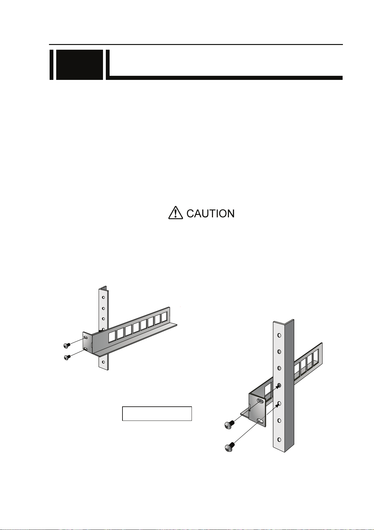
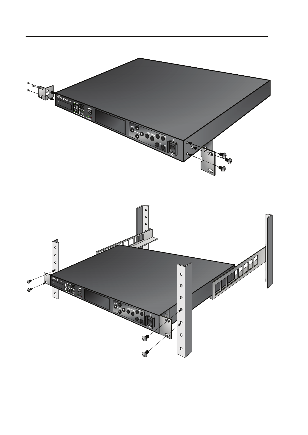
1. 19” rack mounting
Using the mounting kit, it is possible to mount on 19” rack complied EAI standard (1U size).
The mounting kit attached must be used to install. When the installation
is unstable, the serious accident may be caused.
(1) Check all cables disconnected.
(2) Install the rear mounting kit on 19” rack using the four screws.
19” rack rear side
13
IP-9610
Page 28
Chapter 2 Installation and Connection
(3) Install the rack mounting kit on 19” rack using six screws.
(4) Install IP-9610 on 19” rack using the four screws (M5) attached.
IP-9610
14
Page 29

Chapter 2 Installation and Connection
2. Desk-top installation
Install IP-9610 referring Section 2.1.3, “Air flow into and out from the device” and Section
2.1.4, “Open space required around the device” after sticking the five rubber feet (Rack
mounting kit is not required).
01A
11-11
MODEL
H264/AVC CODEC
1.70A-0.71A
D11-0165001
(96CODES-A0)
(96ACMDL-A0)
(96ACMDL-A0)
0.170kVA-0.171kVA
1φ
MADE IN JAPAN
100V-240V~
50/60Hz
7kg
00001
PART NO.
FC40761A1
TA23793-B10X
認証番号
T
FUJITSU LIMITED
Installed Option Part Number
TA23793-B20X
TA22168-B70X
TA22168-B70X
I T E
1K91
E136004
Mark for rubber feet
Safety installation instruction:
1) Multiple pile
The maximum 5 IP-9610 can be piled under the environment condition specified.
Please install considering the maintenance-ability. When IP-9610 are piled,
please fix them to avoid to fall (Do not cover the air intake.). See Section 2.1.4,
“Open space required around the device” for the installation space.
15
IP-9610
Page 30

Chapter 2 Installation and Connection
2) rack mounting
a) When IP-9610 is installed in a closed or multi-unit rack, the operating
ambient temperature inside of the rack environment may be greater than
room ambient. Therefore, the consideration should be given to operate in
the environment compatible with the specifications in Appendix 2.2
“Environment Specifications.”
- The consideration for adjustment of the air condition like air circulation
should be given to prevent the internal rack ambient from exceeding the
maximum operating ambient temperature of IP-9610.
- The maximum operating ambient temperature for IP-9610: 50°C.
b) The installation of IP-9610 in a rack should be such that the amount of airflow
required for safe operation of IP-9610 is not compromised.
- IP-9610 has ventilation opening at the left and rear side.
- Do not cover or close these ventilation openings to prevent overheating.
c) The mounting of IP-9610 in a rack should be such that a hazardous condition
in not archived due to uneven mechanical loading. To keep stability of the
entire rack, please fix the rack to wall or floor by suitable means.
- Be careful about injury during installation of IP-9610 into rack.
- Do not install IP-9610 into your rack where IP-9610 may make the entire
rack unstable.
- The weight of IP-9610 with the maximum configuration: 7 kg
d) If IP-9610 is supplied from the power strip or the service outlet of other units,
it may overload the power supply cord of the power strip or other units.
- Confirm that the current rating of the power strip or the service outlet
exceeds the combined ratings of all equipment is supplying.
- The electrical rating of IP-9610: Rated 100-240 VAC, 1.70-0.71 A, 50/60 Hz,
1 phase.
e) The reliable earthing of the rack-mounted equipment must be maintained.
The particular attention should be given to supply connections other than
direct connections to the branch circuit (e.g., use of the power strips or the
power distribution unit).
Note: The high leakage current may flow through the power strip earthing
conductor if all power supply cords of IP-9610 are connected to one power
strip. The earth connection is essential before connecting supply. If the power
strip is not directly connected to the branch circuit, the power strip which has
the industrial type attachment plug should be used.
2.1.3 Air flow into and out from the device
IP-9610 is forced air cooled. Be sure not to block the air intake/exhaust vents. Provide an
adequate amount of space around the vents.
IP-9610
16
Page 31

2.1.4 Open space required around the device
Provide the indicated (parts with hatched area) below, cable forming space, operation space and
air intake/exhaust.
For the information of maintenance space, see Section 5.3.1, “Maintenance space.”
Chapter 2 Installation and Connection
Apparaten skall anslutas till jordat uttag
SÄKERHETSNOTIS FÖR SVERIGE
Apparatet må tilkoples jo rdet stikkontakt
SIKKERHETS NOTIS FOR NORGE
Laite on liitettävä suojamaadoituskoskettimilla varustettuun pistorasiaa n
SUOMEA KOSKEVAT TURVALLISUUSTIEDOT
17
IP-9610
Page 32

Chapter 2 Installation and Connection
2.2 Power Supply System
2.2
Connections
This section explains ground and power-source connections.
2.2.1 Connection to ground
Use a power cord with the standard two-prong plug with ground wire for FG and external
ground connections.
When the exogenous noise influences IP-9610, connect the FG terminal to an external ground.
Figure Connection to ground
IP-9610
18
Page 33

2.2.2 Connection to power source
IP-9610 operation requires a power supply of 100-240 VAC. Insert the power cord with the
standard two-prong plug with ground into the inlet connector.
The power cord is not supplied with the device. Please procure it separately.
Power inlet connector
1
2
Cable holder
Chapter 2 Installation and Connection
3
4
Figure Power cord connection
AC cable clamp
Insert the AC cable clamp into the AC cable clamp hole and fix the power cord as shown in figure
above. When remove the AC cable clamp, screw out and remove it with the mounting kit.
IP-9610
19
Page 34

Chapter 2 Installation and Connection
USABLE DETACHABLE POWER SUPPLY CABLE SET
MODEL Input Connector Cord Attachment Plug cap
North
America
<*1>
<*2>
Europe
<*2>
Australia
U.K
<*2>
100120V
200240V
100240V
100240V
100240V
IEC C-13
Rated 13A, 125V
UL, CSA Approved
IEC C-13
Rated 15A, 250V
UL, CSA Approved
IEC C-13
Rated 10A, 250V
<*1>
IEC C-13
Rated 10A,
250V
IEC C-13
Rated 10A,
250V
Type SJT, No.16 AWG Min.
3-Conductors
(Single phase;2-current carrying
conductors & ground)
UL, CSA Approved
Type SJT, No.14 AWG Min.
3-Conductors
(Single phase; 2-current carrying
conductors & ground)
UL, CSA Approved
CENELEC OC
3X1.0 square mm<*1>
<HAR>
Cable: AS OD 3 X1.0 square mm
e.g.
BS OC 3 X1.00 square mm Rated 10 A. 250 V
NEMA (5-15P)
parallel blade
Rated 13A, 125V
UL, CSA Approved
NEMA (6-15P)
tandem blade
Rated 15 A, 250 V
UL, CSA Approved
Rated 10 A, 250 V
<*1>
Rated 10 A, 250 V
or
ASA
Japan
100V
IEC C-13
Rated 13A,
125V
METI Approved
or <PSE>
PS
E
Korea
Note: *l. Be sure that the detachable proper Supply cord has the approval of the
220V
(Class I)
220V
(Class II)
appropriate safety agencies of the country where the equipment will be used.
*2. Cable length of above Power Supply cord shall be shorter than 4.5 m.
IEC 60320-1
(IEC C-13)
Rated 12A, 250V
IEC 60320-1
(IEC C-13)
Rated 3A, 250V
Type HVCTF cross section area
1.25 square mm
3-Conductors
(Single phase;2-current
carrying conductors & ground)
METI Approved
or <PSE>
PS
E
Comply with KSC3304.
Type VCTF cross section area 1.25
(0.50 or 1.00 or 2.00) square mm
3-Conductors
(Single phase;2-current
carrying conductors & ground)
Comply with KSC3304.
Type VCTFK cross section area
1.25 (0.50 or 0.75 or 1.00 or 2.00)
square mm
2-Conductors
NEMA (5-15P)
parallel blade
Rated 13 A, 125 V
METI Approved
or <PSE>
PS
E
Comply with KSC8305.
Rated 12A, 250V
Comply with KSC8305.
Rated 12A, 250V
IP-9610
20
Page 35

Chapter 2 Installation and Connection
CERTIFICATION MARKING
Country Agency Certification Mark Country Agency Certification Mark
Austria OVE
Italy IMQ
Belgium CEBEC
Denmark DEMKO
Finland FEI
France UTE
Germany VDE
Possibility of electric shock, fire, and damage to the device
V
DE
Norway NEMKO
Spain AEE
Sweden SEMKO
Switzerland SEV
Always observe the precautions given below.
This indicates a hazardous situation that could lead to electric shock, fire, or
damage to the device.
Always connect the power cord to a power receptacle for the standard
two-prong plug with ground.
Use a power receptacle with a capacity of 1A or more. When using a power
extension cable, be sure that the total power consumption of all devices
connected to the cable does not exceed the rated capacity of the cable. If the
power receptacle capacity is low, or power consumption exceeds the rated value,
the power cord or power wiring may overheat and start a fire.
Possibility of damage to the device
Do not turn on the device until connection of peripheral devices is completed.
Otherwise, the device may be damaged.
100-240 VAC
Using a power cord with the standard two-prong plug with ground, connect
IP-9610 to 100-240 VAC outlet.
Provide a power receptacle for the standard two-prong plug with ground.
IP-9610
21
Page 36

Chapter 2 Installation and Connection
2.3 Connection to External Sync(REF)
2.3
There is each of input and output interfaces for connection to the external sync (REF).
REF input
Connect incoming external sync to REF IN by using coaxial cable with BNC connector. The signal
is terminated in 75 ohm.
REF OUT
Connect coaxial cable with BNC connector to REF OUT for outgoing external sync signal. The
signal is output in 75 ohm.
NOTE:
For details about connectors and
Details.” For electrical specifications, see Appendix 2.3, “Function Specifications.”
cables, see Section 4.2, “Cable and Connector
Figure Connection to External Sync input, output devices
IP-9610
22
Page 37

Chapter 2 Installation and Connection
2.4 Connection to DVB-ASI Device
2.4
This section describes how to connect with the DVB-ASI device.
2.4.1 Connection to DVB-ASI Input Device
When IP-9610 operates with the encoder mode, the BNC cable is connected to DVB-ASI OUT as
shown in the figure below.
For details about connectors and cables, see Section 4.2, “Cable and Connector Details.”
NOTE:
For electrical specifications, see
1
2
Appendix 2.3, “Function Specifications.”
3
4
DVB-ASI input device
Figure Connection to DVB-ASI input device
IP-9610
23
Page 38

Chapter 2 Installation and Connection
2.4.2 Connection to DVB-ASI Output Device
When IP-9610 operates with the decoder mode operates, the BNC cable is connected to DVB-ASI
IN as shown in the figure below. The signal is terminated in 75Ω.
For details about connectors and cables, see Section 4.2, “Cable and Connector Details.”
NOTE:
For electrical specifications, see Appendix 2.3, “Function Specifications.”
Figure Connection to DVB-ASI output device
IP-9610
24
Page 39
Chapter 2 Installation and Connection
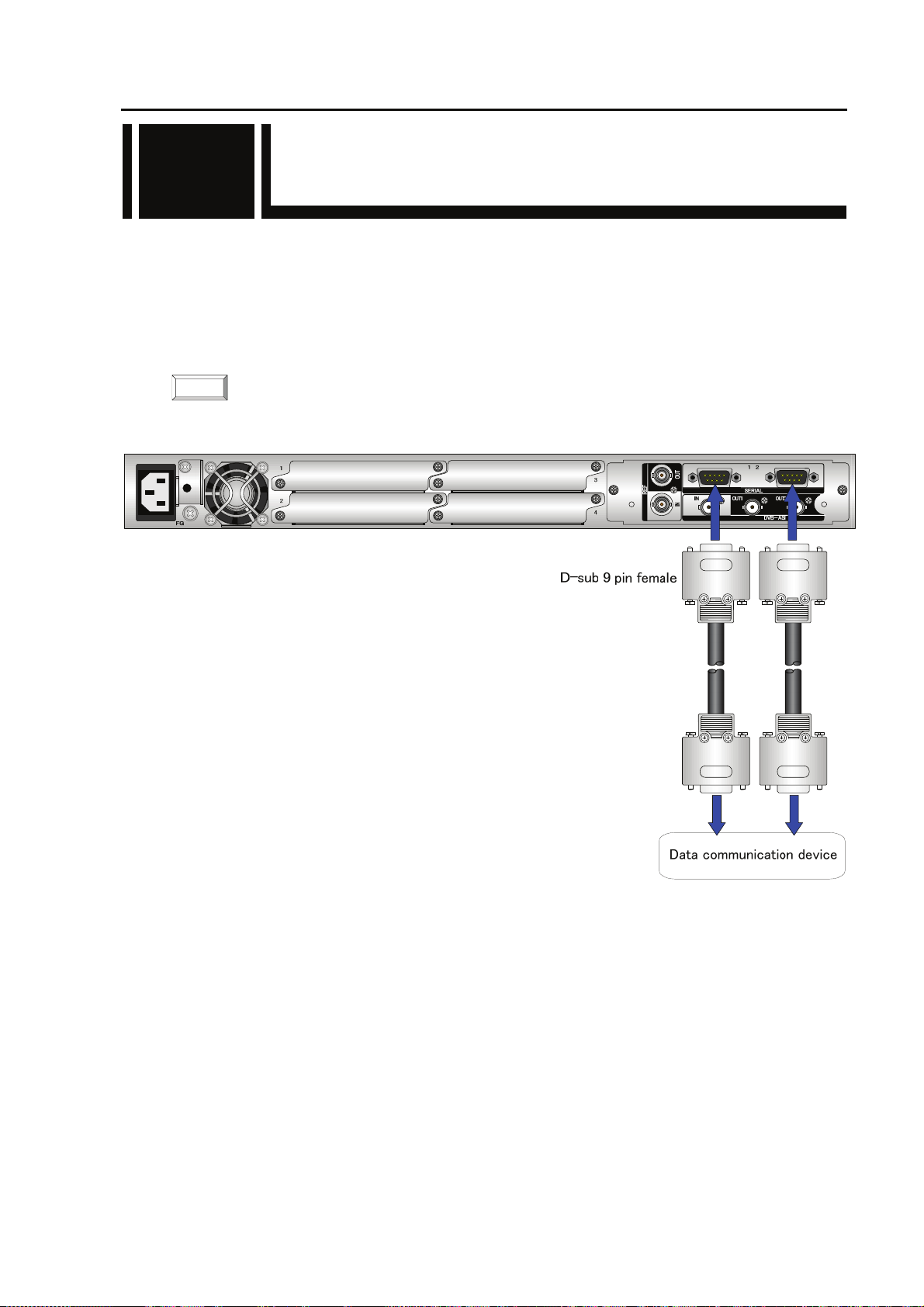
2.5 Connection to RS-232C/RS-422
2.5
Device
The [SERIAL] connector of IP-9610 is the RS-232C or RS-422 communication terminal (switchable).
The terminal of IP-9610 is the D-sub 9 pins (male) . The specification of RS-232C operating mode is
DTE. Use a cross connection or straight cable corresponding to the connected device. See Section 4.2,
“Cable and Connector Details.”
The figure below shows the connection method.
NOTE:
For details about connectors and cables, see Section 4.2, “Cable and Connector Details.”
For electrical specifications, see Appendix 2.3, “Function Specifications.”
Figure Connection to RS-232C or RS-422 input/output device
25
IP-9610
Page 40

Chapter 2 Installation and Connection
2.6 Connection to Network
2.6
To connect IP-9610 to a LAN device, connect the LAN device to the LAN communication port
[CONSOLE/LAN1/LAN2] of IP-9610 using a LAN cable (UTP cable). The LAN communication
port specification of IP-9610 is 10BASE-T/100BASE-TX /1000BASE-T for CONSOLE, LAN1 and
LAN2.
The figure below shows the connection method.
NOTE:
For details about connectors and cables, see Section 4.2, “Cable and Connector Details.”
For electrical specifications, see Appendix 2.3, “Function Specifications.”
NETWORK/CONSOLE
CONSOLE
HUB, Router, etc
Client PC
Figure Connection to network
IP-9610
CAUTION
Please do not provision the IP address below.
LAN/Console ports;
・ IP address commonly unused(0.0.0.0,255.255.255.255,etc…)
・ Loop back address (127.xxx.xxx.xxx)
・ Class D and Class E addresses
・ IP address already used
Console port only;
・IP address (169.254.xxx.xxx) used when LAN port cannot obtain IP address
normally from DHCP server.
For more information, see IP-9610 Software User’s Guide.
26
Page 41

Chapter 2 Installation and Connection
2.7 Connection to Voice
2.7
Communication (Intercom)
Connection to the Voice Communication (Intercom)
For voice communication between IP-9610, there is one voice terminal to connect the voice
communication device (e.g., intercom).
Connect to VOICE terminal on the front panel of IP-9610 using the dedicated adaptor cable with the
bidirectional voice communication terminal (RJ25 – XLR). The impedance is terminated in 600Ω.
There are two types of the cables. Procure the appropriate type separately because this cable is not
attached to IP-9610. For more information, see Section 4.2, "Cable and Connector Details."
NOTE:
For details about connectors and cables, see Section 4.2, “Cable and Connector Details.”
For electrical specifications, see Appendix 2.3, “Function Specifications.”
Figure Connection to voice communication device
27
IP-9610
Page 42

Chapter 2 Installation and Connection
2.8 Optional Board Slot
2.8
IP-9610 provides 4 option slots.
The external interface option board must be assembled in slot #1 at least.
The option board for external interface (video/audio) in each slot of #2~#4 is assembled according to
the system configuration.
Please confirm to an empty slot of an optional slot the installation of the blank board without fail.
The install procedure of optional board is as follows.
Please turn off the power of IP-9610 when the optional board is
WARNING
inserted or removed. Otherwise, it may cause the serious damage to
the device or injury.
IP-9610
28
Page 43

CHAPTER 3
Chapter 3 Operation Instructions
OPERATION INSTRUCTIONS
This section explains how to power on/off, setup and operate the device.
3.1 Power ON/OFF ········································································ 31
3.2 Device Settings and Operation ················································32
3.3 Device Setting and Operation (Front Panel) ····························33
3.4 Special Use of Cancel Key······················································· 34
Page 44

(This page is intentionally left blank)
Page 45

3.1 Power ON/OFF
3.1
This section explains how to power on/off the IP-9610.
3.1.1 Powering on
When the power button on the front panel is set to the [ | ] position, the PWR LED turns on.
When IP-9610 completes preparations for operation, the RDY LED turns on.
Chapter 3 Operation instructions
3.1.2 Powering off
When the power button on the rear panel is set to the [O] position, the device is powered off and
the PWR LED turns off.
31
IP-9610
Page 46

Chapter 3 Operation instructions
3.2 Device Settings and Operation
3.2
■Setup Procedure
The setup procedure is shown below.
See Software User’s Guide for the procedure of the software installation and the each setting.
■Web browser recommended
The supported Web browsers are Internet Explorer, Safari, and Firefox.
Browsers whose operation has been confirmed: Internet Explorer 8, 9
Safari 5
Firefox 5
IP-9610
32
Page 47

Chapter 3 Operation instructions
3.3 Device Settings and Operation
3.3
(Front Panel)
The IP-9610 has six control keys: [U], [V], [Y], [Z], [Enter], [Cancel], [F1], [F2], [F3] and [F4].
Use these keys for making settings.
The VFD panel displays of 4 lines, 24 characters per line.
See Software User’s Guide for the procedure of the software installation and the each setting.
Front Control Panel
■Function description of each key
Functions of [U] and [V] keys
- Each key changes the menu items or setting items displayed on the VFD panel.
- The displayed item changes each time either key is pressed. [U] and [V] change items in
the opposite direction.
Functions of [Y] and [Z] keys
- Each key moves the cursor displayed on the VFD panel to the left or right.
- The cursor moves one column each time either key is pressed.
[Enter] key
- Pressing the [Enter] key while the maintenance initial page is displayed proceeds to the
maintenance menu page.
- Pressing the [Enter] key on the maintenance menu page allows you to make settings for status
display and shutdown.
[Cancel] key
- Pressing the [Cancel] key while the maintenance menu page is displayed proceeds to the
maintenance initial page. Pressing the [Cancel] key on the setting item selection page returns to
the page displayed immediately before you pressed the [Enter] key.
[F1]~[F4] key
- Short cut key to any menu location. By pressing the [F1]~[F4] key, menu location can be changed
to registered location. By pressing the [F1]~[F4] key for a while under the menu location that
customer want to register, that menu location will be registered.
Other
- If you do not make any key input for 60 seconds on any page, the current page proceeds to the
maintenance initial page.
33
IP-9610
Page 48

Chapter 3 Operation instructions
3.4 Special Use of Cancel Key
3.4
You can start IP-9610 by turning on the power while holding down the [CANCEL] key (for
about 10 seconds) until the RDY LED begins blinking in orange. Doing so starts the IP-9610 with
the initial IP address and subnet mask with which the IP-9610 is shipped from the factory
(CONSOLE: IP address 192.168.255.253, Subnet mask 255.255.255.252, LAN1: IP address
10.0.0.1, LAN2: IP address 10.0.0.2, Subnet mask: 255.0.0.0).
Use this function when making initial settings for IP-9610 from a control terminal (such as a PC
having a LAN interface) (*1).
*1 When you operate the IP-9610 with the default IP address, connect the device to a control
terminal and make setting from the terminal with the device disconnected from your network.
After making settings according to the requirements for your network, connect the device to
the network. If the device with the default settings made at the factory is connected to the
network, an unexpected problem may occur with your network.
If you start IP-9610 while holding the [CANCEL] key, set the IP addresses and subnet masks
of the control terminal to connect as follows:
- IP address on CONSOLE : 192.168.255.254
- Subnet mask on CONSOLE : 255.255.255.252
- IP address on LAN : 10.xxx.xxx.xxx
(xxx is any number from 0 to 255, excluding 10.0.0.0, 10.0.0.1, 10.0.0.2 and
10.255.255.255.)
- Subnet mask on LAN : 255.0.0.0
IP-9610
34
Page 49

CHAPTER 4
Chapter 4 Cable Specifications
CABLE SPECIFICATIONS
This chapter contains a type of how work is implemented, cable connection system
diagrams, and cable connector details
4.1 Installation Preparations··························································· 37
4.2 Cable and Connector Details ··················································· 38
Page 50

(This page is intentionally left blank)
Page 51

Chapter 4 Cable specifications
4.1 Installation Preparations
4.1
A type of IP-961 0 installation work is shown below.
IP-9610 External device
BNC
(1) Coaxial cable
BNC
(2) Coaxial cable
BNC
(3) Coaxial cable
BNC
(4) Coaxial cable
BNC
(5) Coaxial cable
DVB-ASI output device
DVB-ASI input device
DVB-ASI input device
Reference clock source
Reference clock source
D-sub9
(6) RS-232C cable
D-sub9
(7) RS-232C cable
(8)Audio adapter cable XLR
RJ25
RJ45
(9) LAN cable
RJ45
(10) LAN cable
RJ45
(11) LAN cable
XLR
Device with RS-232C interface
Device with RS-232C interface
Analog audio output device
(mic, etc)
Analog audio input dev ice
(speaker, etc)
Device with LAN interface (HUB, etc)
Device with LAN interface (HUB, etc)
Device with LAN interface (HUB, etc)
(12) Power cable
(separate order)
Power source 100-240VAC
Cables are depended on the option board.
Please refer user's guide of each option board.
When constructing a system that uses IP-9610, consideration must be given so that its boundary
between IP-9610 and other devices is similar to that shown in the above figure. Since the type of work
may change depending on the system, procure equipment and perform work based on consultations
with a system designer.
IP-9610
37
Page 52

Chapter 4 Cable specifications
4.2 Cable and Connector Details
4.2
(1) DVB-ASI cab le
①
②
Front view
BNC BNC
<IP-9610> <External device>
SG
①
②
SIGNAL
Coaxial cable 75Ω
5C-FB or more
①
②
SIGNAL
SG
DVB-ASI 100m (Coaxial cable 75Ω 5C-FB or more)
Coaxial cable with BNC connector
Product code: TBD
(2) External Sync(REF) cable
①
②
Front view
BNC BNC
<IP-9610> <External device>
Coaxial cable 75Ω
(3C-2V or more)
SIGNAL
REF
Coaxial cable with BNC connector
Product code: TBD
①
②
SG
200m (Coaxial cable 75Ω 3C-2V)
①
②
SIGNAL
SG
IP-9610
38
Page 53

(3) RS-232C / RS-422 cable
⑤ ①
⑨⑥
Front view
D-sub9 (female)
<IP-9610>
CD
RD
SD
DTR(ER)
SG
DSR(DR)
RTS(RS)
CTS(CS)
RI
RS-232C
RS-232C DTE
(DTE)
○
01
○
02
○
03
○
04
○
05
○
06
○
07
○
08
○
09
15 m (Twisted pair cable with shield 24AWG)
RS-422
RxD_N
RxD_P
TxD_N
TxD_P
SG
<IP-9610>
○
01
○
02
○
03
○
04
○
05
○
-
06
○
-
07
○
-
08
○
-
09
100 m (Twisted pair cable with shield 24AWG)
D-sub 9 pin (male)
#4-40 retainer screw
<External device>
(DTE)
○
○
○
○
○
○
○
○
○
<External device>
○
○
○
○
○
CD
RD
SD
DTR(ER)
SG
DSR(DR)
RTS(RS)
CTS(CS)
RI
TxD_N
TxD_P
RxD_N
RxD_P
SG
CD
RD
SD
DTR(ER)
SG
DSR(DR)
RTS(RS)
CTS(CS)
RI
Chapter 4 Cable specifications
<External device side>
RS-232C DCE
<IP-9610>
(DTE)
○
01
○
02
○
03
○
04
○
05
○
06
○
07
○
08
○
09
<External device>
(DCE)
○
CD
○
RD
○
SD
○
DTR(ER)
○
SG
○
DSR(DR)
○
RTS(RS)
○
CTS(CS)
○
RI
39
IP-9610
Page 54

Chapter 4 Cable specifications
(4) LAN cable
IP-9610
40
Page 55
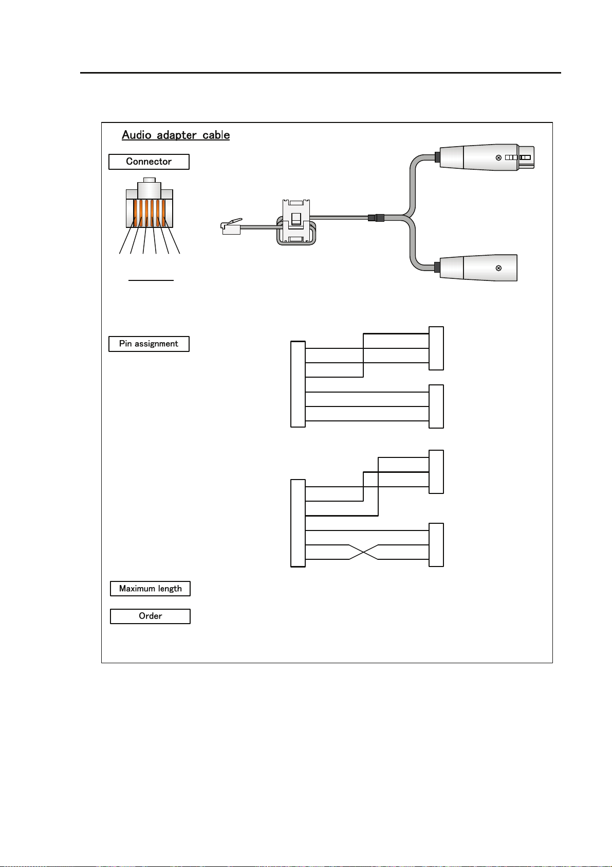
(8) Intercom adapter cable
①②③ ④⑤ ⑥
Front view
Type 1
Type 2
(RJ25)
<IP-9610>
SG
SG
SG
SG
①
②
③
④
⑤
⑥
①
②
③
④
⑤
⑥
AUDIO IN COLD
AUDIO IN HOT
AUDIO OUT COLD
AUDIO OUT HOT
AUDIO IN COLD
AUDIO IN HOT
AUDIO OUT COLD
AUDIO OUT HOT
20m
・Audio adapter cable
Type 1 TA75959-XXXX
Type 2 TA75960-XXXX
Chapter 4 Cable specifications
XLR
XLR
<External device>
①
SG
②
AUDIO IN COLD
③
AUDIO IN HOT
①
SG
②
AUDIO OUT COLD
③
AUDIO OUT HOT
①
SG
②
AUDIO IN HOT
③
AUDIO IN COLD
①
SG
②
AUDIO OUT HOT
③
AUDIO OUT COLD
41
IP-9610
Page 56

Chapter 4 Cable specifications
(9) 100 - 240 VAC power cord
The power supply cord is not contained in this device. Please prepare the cable which suits the
country which uses it.
FG
The form of an outlet changes
with countries which use it.
L1 L2
Front view
<Device side>
L1L2○
○
○
FG
Power inlet cord for 100-240VAC
○
○
○
L1
L2
FG
USABLE DETACHABLE POWER SUPPLY CABLE SET
MODEL Input Connector Cord Attachment Plug cap
North
America
<*1>
<*2>
100120V
IEC C-13
Rated 13A, 125V
UL, CSA Approved
Type SJT, No.16 AWG Min.
3-Conductors
(Single phase;2-current carrying
conductors & ground)
UL, CSA Approved
NEMA (5-15P)
parallel blade
Rated 13A, 125V
UL, CSA Approved
Europe
<*2>
Australia
U.K
<*2>
Japan
200240V
100240V
100240V
100240V
100V
IEC C-13
Rated 15A, 250V
UL, CSA Approved
IEC C-13
Rated 10A, 250V
<*1>
IEC C-13
Rated 10A,
250V
IEC C-13
Rated 10A,
250V
IEC C-13
Rated 13A,
125V
METI Approved
or <PSE>
PS
E
Type SJT, No.14 AWG Min.
3-Conductors
(Single phase; 2-current carrying
conductors & ground)
UL, CSA Approved
CENELEC OC
3X1.0 square mm<*1>
<HAR>
Cable: AS OD 3 X1.0 square mm
e.g.
BS OC 3 X1.00 square mm Rated 10 A. 250 V
Type HVCTF cross section area
1.25 square mm
3-Conductors
(Single phase;2-current
carrying conductors & ground)
METI Approved
or <PSE>
PS
E
NEMA (6-15P)
tandem blade
Rated 15 A, 250 V
UL, CSA Approved
Rated 10 A, 250 V
<*1>
Rated 10 A, 250 V
or
ASA
NEMA (5-15P)
parallel blade
Rated 13 A, 125 V
METI Approved
or <PSE>
PS
E
IP-9610
42
Page 57

Korea
220V
(Class I)
IEC 60320-1
(IEC C-13)
Rated 12A, 250V
Chapter 4 Cable specifications
Comply with KSC3304.
Type VCTF cross section area 1.25
(0.50 or 1.00 or 2.00) square mm
3-Conductors
(Single phase;2-current
carrying conductors & ground)
Comply with KSC8305.
Rated 12A, 250V
220V
(Class II)
IEC 60320-1
(IEC C-13)
Rated 3A, 250V
Comply with KSC3304.
Type VCTFK cross section area
1.25 (0.50 or 0.75 or 1.00 or 2.00)
square mm
Comply with KSC8305.
Rated 12A, 250V
2-Conductors
Note: *l. Be sure that the detachable proper Supply cord has the approval of the
appropriate safety agencies of the country where the equipment will be used.
*2. Cable length of above Power Supply cord shall be shorter than 4.5 m.
CERTIFICATION MARKING
Country Agency Certification Mark Country Agency Certification Mark
Austria OVE
Belgium CEBEC
Denmark DEMKO
Finland FEI
France UTE
Italy IMQ
Norway NEMKO
Spain AEE
Sweden SEMKO
Switzerland SEV
Germany VDE
V
DE
IP-9610
43
Page 58

Chapter 4 Cable specifications
(This page is intentionally left blank)
IP-9610
44
Page 59

CHAPTER 5
Chapter 5 Troubleshooting
TROUBLESHOOTING
This chapter describes actions to be taken if the device does not operate normally or
if an alarm LED turns on.
5.1 Help Information······································································· 47
5.2 Alarm LED Lamp Is On ···························································· 49
5.3 Maintenance ············································································50
Page 60

(This page is intentionally left blank)
Page 61

Chapter 5 Troubleshooting
5.1 Help Information
5.1
If a problem is found in device operation, take recommended action described in the table below,
according to the applicable conditions. If the action does not solve the problem, contact a service
representative.
Possibility of electric shock
Contact your system administrator before checking the voltage of a power
outlet. Otherwise, electric shock may occur.
Table 5.1 Problem descriptions and recommended actions
No. Class Status Description Recommended action
1.
2.
3.
4.
5.
6.
7.
Power cannot
be turned on.
Power
The ALM LED
is blinking.
The ALM LED
Device
is on.
The LEDs
excluding LAN
and Console are
on.
The INDWN
lamp lights in
orange.
Input
Is the power cord connected?
Is the outlet voltage normal?
Check the log information from the
browser.
The temperature inside the device
has risen to the critical level or the
fan speed has fallen.
The device is faulty.
Is the ambient temperature of the
device higher than that in the
specifications?
Is there any shielding material in
the installation space?
Is the power to the video/audio
output device (such as a camera)
selected for input turned on?
Is this device correctly connected to
the video/audio output device?
Make sure that the power cord is properly
connected to the outlet.
Measure the voltage with a tester to
confirm that the voltage is normal.
If another device is connected to the same
outlet, check the operation of the device.
If the ambient temperature of the device is
too high, make proper arrangements to
lower the ambient temperature. If there is
any shielding material in the installation
space, remove it.
If the fan speed is low, the fan needs to be
replaced. Contact a Fujitsu Service
Center.
Troubleshoot from the control terminal.
(For details, see the software manuals.)
Adjust the temperature so that the ambient
temperature of the device meets the
specification's condition.
Remove the shielding material.
Verify the power supply and operation of
the video/audio output device selected for
input.
Check the cable connection between this
device and video/audio output device.
8.
The INDWN
lamp blinks in
orange.
The synchronization slipping
occurs for encoder or the reference
clock input fault occurs for decoder.
47
Make sure that the video input signal for
encoder or the reference clock input signal
for decoder is set correctly.
IP-9610
Page 62

Chapter 5 Troubleshooting
Class Status
No.
Description Recommended action
9.
10.
11.
12.
13.
The LINK/ACT
LED for the
LAN port is not
turned on.
Line
Device setting
through a LAN
is disabled.
Is the power to the communication
destination device turned on?
Are the LINK LEDs on this device
and the hub turned on?
Is the IP address specified from the
Web browser correct?
Are the network settings (IP
address, subnet mask, etc.) on the
control terminal PC correct?
Is a reply received in response to a
PING command issued to the IP
address of the device?
Verify the power supply and operation of
the communication destination device.
If the LINK LEDs are not ON, the LAN
cable is not connected. Connect the LAN
cable correctly.
Specify a correct IP address from the Web
browser on the control terminal.
Make correct settings by referring to the PC
user's guide and OS handbook. If this
device is started with the default settings
made before shipment from the factory, see
"Section 3.4, " Special Use of CANCEL
Key," for the network settings for the
control terminal PC.
If a reply is not received, turn on the power
to the device while holding down the
Cancel key to start the system with the
default IP address (10.0.0.1) set before
shipment from the factory. Confirm the IP
address. If the problem persists, check the
status on the LAN. For information on
this startup procedure, see Section 3.4,
"Special Use of CANCEL Key."
IP-9610
48
Page 63

Chapter 5 Troubleshooting
5.2 Alarm LED Lamp Is On
5.2
This section describes corrective actions to take if an alarm LED turns on.
The appropriate corrective action depends on the alarm code displayed. See Software User’s Guide
for information how to check the alarm log check and an example with displayed information.
In addition, LED display details are given in the following table:
Table 5.2 LED display details
Display Description
PWR Lights in green when the device is powered on.
Blinks in green in the operation preparation state, and lights in green in the operation state.
RDY
INDWN
ALM
Blinks in orange in the maintenance mode waiting state, and lights in yellow in maintenance
mode.
No LED lights in normal state. Blinks in orange in the state of audio/video/network input
down or abnormal.
The alarm display by this LED can select lighting, blinking, and turning off excluding the
LED lighting by the temperature anomaly.
For more details of the alarm log and the setting method of LED, please refer
“IP-9610 Software User’s Guide.”
Alarm LED. Blinks or lights in orange when a device alarm occurs.
Lighting, blinking, and turning off can be selected by the setting about a part of the alarm
display by this LED.
For more details of the alarm log and the setting method of LED, please refer
“IP-9610 Software User’s Guide.”
LINK / ACT
10/100/1000M
Operation status LED of LAN, CONSOLE port.
This LED will be turned on when LINK of Ethernet is established and it will be blinked
when Ethernet packet is detected. It will be turned off when Ethernet cable isn’t connected.
Linked speed information of LAN, CONSOLE port.
This LED will be turned off when linked speed is 10BASE, it will be turned on when linked
speed is 100BASE, and it will be blinked when linked speed is 1000BASE.
49
IP-9610
Page 64

Chapter 5 Troubleshooting
5.3 Maintenance
5.3
5.3.1 Maintenance space
When the operators do the maintenance work, the maintenance space below is required in addition
to Section 2.1.4, “Installation space.”
Desk-top installation:
Please allocate the space more than 1 m in front
or rear for maintenance.
Flont space
for maintenance
> 700×1000 mm
Front access case
Rear space
for maintenance
> 700×1000 mm
Rear access case
Rack installation:
Please allocate the space more than 1 m in
front and rear for maintenance.
Rear space
for maintenance
> 700×1000 mm
Flont space
for maintenance
> 700×1000 mm
IP-9610
50
Page 65

5.3.2 Change of maintenance parts (Maintenance only)
If there is no improvement of situation after checking and dealing with referring Section 5.1,
“Help Information,” change the hardware following the procedure below.
This device itself is a repair unit.
In case of a malfunction, please change this device itself.
Chapter 5 Troubleshooting
51
IP-9610
Page 66

(This page is intentionally left blank)
I
Page 67

Appendix
Appendix
The appendix contains view of the device and its main specifications. Notes on
installation work and preparations for on-site turn-up are also contained in this
section.
A.1 Appearance·············································································· 55
A.2 Basic Specifications ································································· 57
A.3 Preparations for Installation Work ············································ 62
A.4 Preparations for On-site Turn-up·············································· 63
Page 68

(This page is intentionally left blank)
Page 69
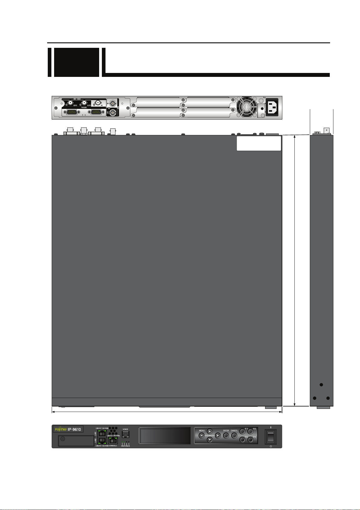
A.1 Appearance
A.1
The appearance of IP-9610 is shown below.
4
3
425±4 mm
Appendix
2
1
43±1.5
mm
Apparaten skall anslutas till jor dat uttag
SÄKERHETSNOTIS FÖR SVERIGE
Apparatet må tilkoples jo rdet stikkontakt
SIKKERHETS NOTIS FOR NORGE
Laite on liitettävä suojamaadoi tus koskettimilla varustettu un pistorasiaan
SUOMEA KOSKEVAT TURV ALLISUUSTIEDOT
500±4 mm
55
IP-9610
Page 70

Appendix
01A
11-11
MODEL
H264/AVC CODEC
1.70A-0.71A
00001
PART NO.
TA23793-B10X
FC40761A1
認証番号
T
D11-0165001
0.170kVA-0.171kVA
100V-240V~
1φ
50/60Hz
7kg
FUJITSU LIMITED
Installed Option Part Number
TA23793-B20X
TA22168-B70X
TA22168-B70X
I T E
1K91
E136004
(96CODES-A0)
(96ACMDL-A0)
(96ACMDL-A0)
MADE IN JAPAN
IP-9610
Bottom View
56
Page 71

A.2 Basic Specifications
A.2
This chapter describes the external specifications, environment specifications, and function
specifications of the device.
A.2.1 External specifications
The device has the following external specifications:
Item Specifications
Installation conditions Indoor: Installation on a desk or in a rack that is mounted
Dimensions
Cooling method Forced air cooling (maintenance-free fan used)
Power 100-240VAC
Weight Max. 7 kg
Power consumption
Width: 425, Height: 43, Depth: 500 (mm) (Excluding protrusions)
Width: 425, Height: 46, Depth: 520.3 (mm) (Including optional board, etc)
170 VA or less (100V AC)
171 VA or less (240V AC)
A.2.2 Environment specifications
The device has the following environmental specifications:
Item Specifications
Power conditions
Temperature and humidity
conditions
Dust
EMI
(Electro Magnetic
Interference - regulation)
100-240 VAC ± 10%, 50/60 Hz ± 3 Hz
Temperature: 0 to 50°C
Humidity: 20 to 90% (without condensation)
(Conditions for guaranteed operation and characteristics)
Communication equipment room or office environment
(0.2 mg/m
FCC (part 15) Class A
EN55022 Class A
VCCI Class A
3
or less)
Appendix
IP-9610
57
Page 72

Appendix
A.2.3 Function specifications
This chapter describes functional specifications of individual parts of the device.
<Main Component>
Name Specifications Remarks
Signal format: NRZI
DVB-ASI
input
Connector name SDI IN BNC
Pin number Signal name Remarks
1
2
Name Specifications Remarks
DVB-ASI
output
Connector name SDI OUT BNC
Pin number Signal name Remarks
1
2
Input impedance: 75Ω (Unbalanced)
Minimum signal amplitude: 200mVp-p
Maximum amplitude level: 800mVp-p ± 10%
SIGNAL
SG
Signal format: NRZI
Output impedance: 75Ω (Unbalanced)
Signal amplitude: 800mVp-p
Maximum amplitude level: 800mVp-p ± 10%
SIGNAL
SG
1
1
2
2
Name Specifications Remarks
Signal format: NTSC w/o SETUP (Analog composite, 29.97frames/s)
Reference
clock output
Connector
name
Pin number Signal name Remarks
1
2
Name Specifications Remarks
Reference
clock input
Connector
name
Pin number Signal name Remarks
1
2
PAL (Analog composite, 25frames/s)
Output impedance: 75Ω (Unbalanced)
Signal amplitude: 1.0 Vp-p
REF OUT BNC
SIGNAL
SG
Signal format: NTSC w/o SETUP (Analog composite, 29.97frames/s)
NTSC w/ SETUP (Analog composite, 29.97frames/s)
PAL (Analog composite, 25frames/s)
HD Tri-SYNC (29.97/25frames/s)
Input impedance: 75Ω (Unbalanced)
Signal amplitude: 1.0 Vp-p
REF IN BNC
SIGNAL
SG
1
1
NTSC/PAL Black burst
NTSC/PAL Black burst
or
2
Y/Pb/Pr Three values
sync (Black)
2
IP-9610
58
Page 73

Appendix
Name Specifications Remarks
Data interface
(RS-232C)
No. of CH
Signal system
Connection
Bit rate
Data length
Parity
Stop bit
flow control
DTR signal monitoring
: 2 ch
: Asynchronous
: DTE
: 1200, 2400, 4800,9600, 19200, 38400 bps
: 8
: NONE
: 1
: NONE / RS,CS
: Enable / Disable
RS-232C interface
Connector name SERIAL D-sub 9 pin(male)
Pin number Signal name Remarks
1
2
3
4
5
6
7
8
9
CD
RD
SD
DTR (ER)
SG
DSR (DR)
RTR (RS)
CTS (CS)
RI
Carrier Detect
Receive Data
Send Data
Data Terminal Ready
Signal Ground
Data set Ready
Request to Send
Clear to Send
Ring Indicator
①⑤
⑥
⑨
Name Specifications Remarks
Data interface
(RS-422)
No. of CH
Signal system
Connection
Bit rate
Data length
Parity
Stop bit
: 2 ch
: Asynchronous
: DTE
: 1200, 2400, 4800,9600, 19200, 38400 bps
: 8
: NONE
: 1
RS-422 interface
Connector name SERIAL D-sub 9 pin(male)
Pin number Signal name Remarks
1
2
3
4
5
6
7
8
9
RxD_N
RxD_P
TxD_N
TxD_P
SG
-
-
-
-
Receive Data N
Receive Data P
Transmission Data N
Transmission Data P
Signal Ground
-
-
-
-
①⑤
⑥
⑨
Name Specifications Remarks
Analog AUDIO
input /output
(VOICE)
Connector name
Pin number Signal name Remarks
1
2
3
4
5
6
Signal format: Analog audio
Input / output impedance: 600Ω (Balanced)
Maximum amplitude level: 20dBm , 0dBm
VOICE RJ25
IN COLD
IN HOT
SG
SG
OUT COLD
OUT HOT
①②③④⑤⑥
59
IP-9610
Page 74

Appendix
Name Specifications Remarks
[10BASE-T]
System standard: IEEE802.3
Transmission clock: 10Mbit/s±10000ppm(±0.01%)
Load impedance: 100Ω
Transmission coding: Manchester coding
[100BASE-TX]
System standard: IEEE802.3u
LAN interface
Connector name
Pin number Signal name Remarks Signal name Remarks
1
2
3
4
5
6
7
8
Transmission clock: 125 Mbit/s±5000ppm(±0.005%)
Load impedance: 100Ω
Transmission coding: 4B5B
[1000BASE-T]
System standard: IEEE802.3ab
Transmission clock: 1000 Mbit/s±10000ppm(±0.1%)
Load impedance: 100Ω
Transmission coding: 8B1Q4
10/100 BASE
CONSOLE
TD+
TDRD+
N.C.
N.C.
RDN.C.
N.C.
Trans. data+
Trans. data-
Reciv. data+
-
-
Reciv. data-
-
-
10/100/1000 BASE
LAN
TP0+
TP0TP1+
TP2+
TP2-
TP1TP3+
TP3-
Pair 0+
Pair 0Pair 1+
Pair 2+
Pair 2-
Pair 1Pair 3+
Pair 3-
RJ-45
8 7 6 5 4 3 2 1
Cable
Name Specifications Remarks
Standard: ANSI/TIA/EIA568A CAT5
Pin assignment: Comply with one of two below
Pin No. 1 2 3 4 5 6 7 8
T568A W/G G W/O Bl W/Bl O W/Br Br
T568B W/O O W/G Bl W/Bl G W/Br Br
[W: white, G: green, O: orange, Bl: blue, Br: brown]
Parallel 2 pin with ground
Input voltage
POWER
Connector name
Pin number Signal name Remarks
1
2
3
Connector
Button
Input protection
Withstand voltage
L1
L2
FG
: 100-240VAC±10%
: Inlet
: Locker button
: Built-in fuse
: 1,500 VAC
3
1
FG
L1 L2
2
IP-9610
60
Page 75

Appendix
LED name ON Blinking OFF Remarks
PWR G Power ON --- Power OFF
G Normal operation Starting up RDY
O
Maintenance mode
LAN1
(IP=10.0.0.1)
LAN2
(IP=10.0.0.2)
CONSOLE
(IP=192.168.255.253)
ALM R Equipment alarm Equipment alarm Normal operation When the device
IN DWN O Video/Audio/Network
input down/fault
LINK/ACT
[LAN1]
100M/1000M
[LAN1]
LINK/ACT
[LAN2]
100M/1000M
[LAN2]
LINK/ACT
[CONSOLE]
100M/1000M
[CONSOLE]
G LINK established LAN packets detection Cable disconnection
G 100BASE operation 1000BASE operation 10BASE operation
G LINK established LAN packets detection Cable disconnection
G 100BASE operation 1000BASE operation 10BASE operation
G LINK established LAN packets detection Cable disconnection
G 100BASE operation 1000BASE operation 10BASE operation
Maintenance mode
starting up
Video/Audio/Network
input down/fault
Software inactive Blink interval: 0.5s
Maintenance mode
(Cancel button
startup):
LAN subnet mask
(255.0.0.0)
CONSOLE subnet
mask
(255.255.255.252)
alarm is generated, a
part of alarm can be
changed to lighting,
blinking, and turning
off by the setting.
Normal operation
The alarm display by
this LED can select
lighting, blinking,
and turning off
excluding the LED
lighting by the
temperature anomaly.
G: Green, O: Orange, R: Red
Name Button type Specifications Behavior
POWER Locker button Power ON/OFF
61
IP-9610
Page 76

Appendix
A.3 Preparations for Installation Work
A.3
This section contains notes and describes check items for installation work.
A.3.1 Scope of installation work
For details about the scope of installation work, see Section 4.1, “Installation Preparations.”
A.3.2 Unpacking and device check
Unpack and check the device as follows:
• During unpacking, carefully handle the device so as not to apply shock to it or damage its
appearance.
• Make sure that the device and accompanying package are not damaged.
• Make sure that wiring does not have a short circuit and is not disconnected.
• Make sure that no incorrect screw is contained in the package.
A.3.3 Installation conditions
For the classification of this work, see Section 2.1, “Installation Conditions.”
The installation method may differ depending on the site where the device is installed. In
principle, the installation method conforms to the appropriate method for the site.
Do not install the device at the following locations:
• Place exposed to direct sunlight or near a heater.
• Humid or dusty place
• Place where the device is exposed to shock or vibration
• Unstable place, such as on a slope or place with a lot of weight on it
• Place where the device is subject to strong magnetic and radio waves
A.3.4 Connecting external cables
Refer to Chapter 2, “Installation and Connection,” for the connection methods, Section 4.2,
“Cables and Connector Details,” and A.2.3, “Function specifications,” for device connector pin
assignments.
IP-9610
62
Page 77

A.4 Preparations for On-site
A.4
Turn-up
This chapter explains the workflow of on-site turn-up.
START
START
準備
Preparations
環境確認
Environment check
Visual check of
員数確認
外観目視確認
appearance
ケーブル接
Cable connection
版数確認
check
続
Input voltage check
入力電圧確認
Appendix
Power on
電源投入
Unit test
単体試験
System test
システム試験
EN
END
D
Since system configurations of the device are diverse depending on the applications used, this chapter
describes the checking process for only a single device.
63
IP-9610
Page 78

Appendix
(1) Preparations
1) Check the system configuration
Check the entire system configuration.
2) Check the units and cables to be connected to the device
Check the units to be connected to the device, cables that have to be procured, and
installation conditions.
3) Tools and measuring instruments necessary for work:
• Digital multimeter
• General-purpose tools
(2) Environment check
1) Ambient air temperature, humidity and power supply
Make sure that the ambient air temperature, the humidity and power supply conform to
A.2.2, “Environment Specifications.
2) Ground connection (FG)
Make sure that use a grounding resistance of 100 ohms, a wire of 2mm
your country’s applicable standard.
(3) Visual check of appearance
1) Make sure that the device surface has no damage such as scratches, dirt, rust,
deformation or peeling of its coating.
2) Make sure that patent nameplate and device nameplate are still attached, and that
buttons are not damaged.
3) Make sure that connectors are not loose.
2
or thicker, or
(4) Cable connection check
Make sure that individual cables are connected as prescribed in system specifications.
Refer to Chapter 2, “Installation and Connection,” for the connection methods, Section 4.2,
“Cables and Connector Details,” and A.2.3, “Function specifications,” for device connector
pin assignments.
Hardware settings need not be set in the device.
(5) Input voltage check
Make sure that the voltage of power supplied to the device is in a range of 100-240 VAC
± 10%.
IP-9610
64
Page 79

(6) Power on
(7) Unit test
(8) System test
Appendix
1) Set Power button on the front panel to [ON].
2) Make sure that that PWR LED lamp on the front panel is on.
1) Since this device executes a self-check immediately after power is turned on, make
sure that the RDY LED
on the front of the panel does not light after power is turned
on.
2) The LEDs light if the self-check detects an unusual condition.
1) Set-up check
Various devices settings complying with the system specification are made from the
control terminal either directly or via the network.
2) Input video check
Make sure that the video input to the device is correctly output to the monitor
(television).
3) Data communication check
Make sure that the line used by the system is connected.
Status check
4)
After the final setup, when the equipment is in the system operation state, make sure
that the device status LED (RDY) on the front of the device lights in green, and that the
alarm LED (ALM) is off.
65
IP-9610
Page 80

(This page is intentionally left blank)
Page 81

Glossary and Index
Glossary ····························································································· 69
Index··································································································· 72
Glossary and Index
Page 82

(This page is intentionally left blank)
Page 83

Glossary
AES/EBU
This is the standard of the professional digital
audio signals and standardized by AES and EBU.
ANSI adopts it too.
Glossary and Index
Embedded Audio
It is the scheme to embed (multiplex) AES/EBU
digital audio signals in the auxiliary data area
(blanking area) of the serial digital signal.
Alarm Log
Record of errors that have occurred on devices
and communication lines
BNC (Bayonet Neill Concelman)
Type of coaxial connector whose characteristic
impedance is 75
bayonet lock is used, ensuring cables are easy
to connect and remove, and secure connections.
The connector is compact and lightweight and
has a frequency range compatible with the high
frequency of 4 GHz, so it can be used for
measuring instruments and digital audio
equipment.
Ω. A locking system called a
Browser
General name for programs that support users
who want to select desired options from
available options. Using a browser, a user can
trace links on the Internet to access such
multimedia information as text, audio, and video
by simply using a pointing device (e.g., mouse)
to select items.
DCE (Data Circuit terminating Equipment)
Data circuit terminating equipment. DCE is a
term from ITU-T. Similar to modems and DSUs,
it changes signals to waveform that are suitable
for their transmission routes.
DHCP (Dynamic Host Configuration Protocol)
This is the protocol to assign IP address
dynamically when startup and to release it when
shutdown. The IP address prepared by DHCP
server is assigned.
DTE (Data Terminating Equipment)
Data terminating equipment. It is one kind of
terminal equipment (e.g., PC). DTE is a term
from ITU-T and is paired with DCE.
DVB-ASI (Digital Video Broadcasting
- Asynchronous Serial Interface)
This is the standard interface in DVB (Digital
Video Broadcasting: European Digital
Broadcasting standardization organization) and
used in MPEG CODEC most commonly. It is the
asynchronous serial interface and standardized
in ETSI 101 891.
FG (Frame Ground)
Ground for a cabinet
Flow Control
Procedure for controlling the flow of data
between two devices. Its purpose is to prevent
data loss when the device buffer becomes full.
Gateway
Equipment that connects network systems that
use different protocols. It basically converts
one protocol into another to support operation
between two networks. In a broader sense, a
gateway sometimes means a device that
transfers information between any two networks.
HD-SDI (High Definition television – Serial
Digital Interface)
HD-SDI is the serial digital interface to transmit
HD (High Definition) video signal, which
transmission rate is 1.485 Gbps. It can transmit
multiplexing HD video signal, PCM audio signal
and data signal like time stamp.
H.264
This is one of the video compression coding
systems standardized in ITU (International
Telecommunication Union) in May, 2003. It is
also standardized as a part of MPEG-4 (MPEG-4
part 10 Advanced Video Coding) in ISO
(International Organization for Standard).
Therefore, it is commonly called H.264/MPEG-4
AVC or H.264/AVC, showing both of parties.
This technology is used for the various
applications from the low bit rate and low
resolution like the mobile TV to the high bit rate,
high resolution like HDTV. It is improved that the
data capacity is half comparing MPEG-2 used
wide spread.
HTTP (Hyper Text Transfer Protocol)
Protocol used for sending and receiving files
and other data between a WWW server and
WWW browser
Hub
Concentrator required for using 10BASE-T or
100BASE-TX as a local area network (LAN)
standard. Twisted-pair cables are used to
connect hubs. A high-speed hub conforms to
69
IP-9610
Page 84

Glossary and Index
100BASE-TX, and a switching hub has switching
functions.
IP (Internet Protocol)
Protocol used between host computers to
transfer packets over all of the Internet. The
codes that identify the destinations and senders
in packet transfers are called IP addresses. An
IP address is a 32-bit code that can identify a
network and host in the network. A unique IP
address must be allocated to each hosts that
communicates on the Internet.
IP Address
Code used for identifying a node (e.g., PC)
operating using TCP/IP. This 32-bit number is
divided into four 8-bit sections, and an example
of this is 200.10.101.1.
IP Multicast
Technology for transmitting identical data to
multiple remote destinations simultaneously using TCP/IP. An address system called class D
is used for multicasting. In the class D address
system, the first four bits (1110) indicate a multicast, and the remaining 28 bits specify a
multicast group. Path control methods for IP
multicasting are PIM and DVMRP, but no one
method has become the standard yet.
LAN (Local Area Network)
Data communication system in a specific area
(maximum of 6 miles or about 10 km). It
provides moderate to high data transfer speeds.
LED (Light-Emitting Diode)
The IP-9610 has a power LED lamp and
alarm LED lamps. The power LED lamp is lit
in green to indicate the device is on. An
alarm LED lamp is lit in red to indicate that an
alarm has been generated.
communication by general-purpose multimedia
encoding systems on mobile terminals.
PING
Command supported by operating systems such
as UNIX, Windows 9x, and Windows NT, and it is
used in TCP/IP networks to check whether IP
packets can reach or have reached their
communication destinations
PPPoE (Point to Point Protocol over Ethernet)
This is the user authentication standard for the
connection like PPP connection on the Ethernet
network.
PS
MPEG-2 method of multiplexing audio, video,
and data. It is an abbreviation of Program
Stream, and it is used for transmission and
storage in an error-free environment.
RS-232C
Interface standard that was mainly established by
the Electronics Industry Association (EIA) for
communication between data terminals and data
communications equipment
RS-422
A serial communication standard is standardized
by the Electronic Industries Alliance (EIA). RS-422
can make transmission robust against noise. It
supports cable lengths of up to 1.2 km and
communication speeds of up to 10 Mbps
SD-SDI (Standard Definition television – Serial
Digital Interface)
Standard definition digital video interface
standardized in SMPTE259M.
SG (Signal Ground)
Ground for signals
MPEG-4
Standard for the compression and coding
of color video for storage purposes, and the
name of the organization promoting this
standardization is used in the name of the
standard. MPEG-4 handles not only regular
image and voice data but also a comprehensive
range of multimedia data, including computer
graphics and text. It defines a flexible
framework for a scalable object encoding system
depending on technological developments. It
has a transfer speed ranging from several tens
of Kbps to several tens of Mbps (low bit rate
to wide range). It is intended for low-speed
IP-9610
Subnet Mask
Mask value used for obtaining a subnet network
address from an IP address. The subnet
address is obtained by using an AND operation
between an IP address and subnet mask.
TCP (Transmission Control Protocol)
Abbreviation of Transmission Control Protocol,
which is the protocol required for direct connection
to the Internet. In the OSI reference model, TCP
corresponds to the transport layer and IP
corresponds to the network layer. TCP has been
a global standard protocol that is supported by
major operating systems, including UNIX, OS/2,
Windows 95, and Windows NT.
70
Page 85

Glossary and Index
TS (Transport Stream)
The stream used in the multi-programs
multiplexing, standardized in MPEG-2 systems.
The transport stream offers features for error
correction for transportation over unreliable media,
and is used in broadcast applications and ATM
telecommunication.
TTL (Time To Live)
Abbreviation of time to live, which indicates the
survival time of a packet in a network. If a packet
sent to a network happens to enter a loop because
of a setting error on a router, it will not survive
forever but will be discarded when the time
specified in the Time To Live field of the IP header
is reached.
UDP (User Datagram Protocol)
Abbreviation of User Datagram Protocol, which is
a TCP/IP transaction protocol used for specific
applications such as remote network management
and naming service access
Unicast
Communication with a station at a single address
(i.e., most general one-to-one communication)
UTP Cable
Abbreviation of unshielded twisted pair. It is a
unshielded pair of wires twisted together, and
these wires are used for Ethernet cabling and
other purposes.
VFD
Vacuum Fluorescent Display. Because VFD emits
by itself, the contrast is clear rather than LCD. Wide
temperature range for operation makes less
influence to functions.
10BASE-T
LAN that uses unshielded twisted-pair (UTP)
cables and complies with the IEEE 802.3
standard. A 10BASE-T connection uses a
concentrator called a hub. It is widely used
because special cabling work is not necessary
and wiring can be done easily. The maximum
length of cable wiring is 100 m.
100BASE-TX
One of the 100BASE LAN standards (also
called Fast Ethernet), it supports a transfer rate
of 100 Mbps. Other 100BASE standards are
10BASE-T4 and 100BASE-FX, and the difference is the type of cable used. 100BASE-TX
uses unshielded twisted-pair (UTP) cables. It
also uses the RJ-45 connector, which is similar
to the modular jacks used for telephones.
1000BASE-T
One of the Gigabit Ethernet standards. It
standardized as IEEE802.3ab in 1999, uses the
UTP cables of the category 5 (CAT5) and the
enhanced category (CAT5e). The maximum
transmission distance is 100m and it supports
the topology of the hubbing, star and so on.
3G-SDI
A family of interfaces used in the high-definition
video transmission required for 1080p and digital
cinema.With a transmission capacity as high as
3 Gbps, 3G-SDI enables transmission of 1080/
60p signals through a single BNC cable.
71
IP-9610
Page 86

Glossary and Index
Index
1
1000BASE-T ..................................... 3, 7, 26, 60
100-240VAC .................................... 3, 21, 57, 60
100-240VAC power cord .................................. 42
100BASE-TX .................................... 3, 7, 26, 60
10BASE-T ......................................... 3, 7, 26, 60
A
Alarm LED .......................................................... 8
Alarm LED lamp .............................................. 49
Analog AUDIO input /output .......................... 59
Appearance......................................................... 55
Appendix ............................................................53
Audio board......................................................... 4
Audio input.......................................................... 3
Audio output........................................................ 3
AV input status LED.......................................... 8
B
Basic application examples ................................ 6
Basic specifications ........................................... 57
BNC.................................................................... 38
D
Data input/output .................................................3
Data interface..................................................... 59
Device Settings and Operation ........................ 32
Device Settings and Operation (Front Panel) 33
Dimensions ....................................................3, 57
Direction key ....................................................... 8
Dust..................................................................... 57
DVB-ASI cable.................................................. 38
DVB-ASI input....................................................9
DVB-ASI output..................................................9
E
Enter key.............................................................. 8
Environment specifications................................57
External specifications....................................... 57
External Sync(REF) cable ................................ 38
F
FAN ...................................................................... 8
FG terminal.......................................................... 8
Function specifications ......................................58
C
Cable and connector details............................. 38
Cable Specifications .......................................... 35
Cancel key ........................................................... 8
Change of maintenance parts........................... 51
Codec board......................................................... 4
Components.......................................................... 5
Connecting external cables............................... 62
Connection to DVB-ASI Device ..................... 23
Connection to DVB-ASI Input Device........... 23
Connection to DVB-ASI Output Device ........ 24
Connection to External Sync(REF) ................. 22
Connection to network...................................... 26
Connection to power source ............................ 19
Connection to RS-232C/RS-422 Device .........25
Connection to Voice Communication (Intercom)
........................................................................ 27
Cooling method ................................................. 57
Cooling system .................................................... 3
IP-9610
G
Glossary .............................................................. 69
Glossary and Index ........................................... 67
H
Help Information ............................................... 47
Humidity........................................................ 3, 57
I
Index ...................................................................72
Installation and Connection .............................. 11
Installation conditions..................... 3, 13, 57, 62
Installation preparations.....................................37
Intercom adapter cable...................................... 41
IP address.................................................... 34, 48
72
Page 87

L
LAN cable.......................................................... 40
LAN interface ....................................................60
Glossary and Index
RS-232C.........................................................9, 25
RS-232C cable ...................................................39
RS-232C interface..............................................59
RS-232C port .......................................................9
RS-422 cable......................................................39
M
Main features .......................................................3
N
Network ................................................................3
O
Operation Instructions........................................29
Optional board slot............................................28
P
Part names............................................................7
Power ...........................................................57, 60
Power button........................................................8
Power consumption.......................................3, 57
Power inlet connector .........................................8
Power LED .......................................................... 8
Power ON/OFF .................................................. 31
Power supply........................................................3
Power supply system connections ................... 18
Powering off ...................................................... 31
Powering on .......................................................31
Preparation for installation work .....................62
Preparations ..........................................................1
Preparations for On-site Turn-up.....................63
S
Scope of installation work................................62
SD CARD slot................................................3, 7
SDI input board...................................................4
SDI output board.................................................4
Setup procedure .................................................32
Special Use of Cancel Key..............................34
Status LED...........................................................8
T
Temperature ...................................................3, 57
Troubleshooting ..................................................45
U
Unpacking and device check............................62
USB..................................................................3, 7
UTP cable...........................................................26
V
VFD panel.....................................................8, 33
Video input....................................................3, 58
Video output.........................................................3
Voice input/output ...............................................3
W
R
Reference clock input .................................. 3, 58
Reference clock output ....................................... 3
Relay contact input ............................................. 9
Web browser recommended..............................32
Weight ............................................................3, 57
IP-9610
73
Page 88

Glossary and Index
CE Conformity Information
Following address can be reached at for regarding the CE conformity information.
Fujitsu Services Limited
Address: 22 Baker Street, London, W1U 3BW, United Kingdom
URL: http://uk.ts.fujitsu.com/support/
IP-9610
74/74
Page 89

IP-9610 User’s Guide
November, 2011 1st Edition
© FUJITSU LIMITED
Page 90

 Loading...