

Page 1

T101-1209-01EN 01
IP-9500e
User’s Guide
Page 2

(This page is intentionally left blank)
Page 3

IP-9500e
i
USING IP-9500e SAFELY
Handling of This Manual
The manual contains important information regarding the safe use of IP-9500e. Read it thoroughly
before operating this device. Make sure that users of the device read and understand thoroughly all
safety precautions contained in the manual. Keep this manual in a safe and convenient location for
quick reference.
Fujitsu makes every effort to prevent users and bystanders from injury and to prevent property damage.
To ensure no harm to you and bystanders, and to prevent damage to the device itself, be sure to use
IP-9500e in accordance with instructions
in the manual.
The following notice is for USA users only.
IP-9500e has been tested and found to comply with the limits for a Class A digital device, pursuant to
Part 15 of the FCC Rules. These limits are designed to provide reasonable protection against harmful
interference when the equipment is operated in a commercial environment. This equipment generates,
uses, and can radiate radio frequency energy and, if not installed and used in accordance with the
instruction manual, may cause harmful interference to radio communications. Operation of this
equipment in a residential area is likely to cause harmful interference in which case the user will be
required to correct the interference at his own expense.
The following notice is for Canada users only.
This Class A digital apparatus meets all requirements of the Canadian Interference-Causing Equipment
Regulations.
The following notice is for EU (European Union) users only.
This is Class A product of Electromagnetic Interference (EMI) standard. In a domestic environment
this product may cause radio interference in which case the user may be required to make adequate
measures.
This manual includes technology controlled under the Foreign Exchange and Foreign Trade Control
Law of Japan. The manual or a portion thereof must not be exported (or re-exported) without
authorization from the appropriate governmental authorities in accordance with the above law.
IP-9500e is designed and manufactured for use in standard applications such as office work, personal
devices, and household appliances. The product is not intended for special uses (such as
nuclear-reactor control in atomic energy facilities, aeronautic and space systems, air traffic control,
operation control in mass transit systems, medical devices for life support, and missile firing controls in
weapons facilities) where particularly high reliability requirements exist, where the pertinent levels of
safety are not guaranteed, or where a failure or operational error could threaten a life or cause physical
injury (hereafter referred to as "mission-critical" use). Customers considering use of this product for
mission-critical applications must have safety-assurance measures in place beforehand. Moreover,
they are requested to consult our sales representative before embarking on such specialized use.
Copying of and disassembly, decompilation and other forms of reverse engineering of any program
included with this device is prohibited.
Microsoft, Windows, Windows NT, Windows 2000, and Windows XP are registered trademarks or
trademarks of Microsoft Corporation in the United States and/or other countries.
Page 4

IP-9500e
ii
IMPORTANT NOTE TO USERS
READ THE ENTIRE MANUAL CAREFULLY BEFORE USING THIS PRODUCT.
INCORRECT USE OF THE PRODUCT MAY RESULT IN INJURY OR DAMAGE TO
USERS, BYSTANDERS OR PROPERTY.
While FUJITSU has sought to ensure the accuracy of all information in this manual, FUJITSU assumes
no liability to any party for any damage caused by any error or omission contained in this manual, its
updates or supplements, whether such errors or omissions result from negligence, accident, or any other
cause. In addition, FUJITSU assumes no liability with respect to the application or use of any product or
system in accordance with descriptions or instructions contained herein; including any liability for
incidental or consequential damages arising therefrom.
FUJITSU DISCLAIMS ALL WARRANTIES REGARDING THE INFORMATION
CONTAINED HEREIN, WHETHER EXPRESSED, IMPLIED, OR STATUTORY.
FUJITSU reserves the right to make changes to any products described herein without
further notice
and without obligation.
No part of this manual shall be reproduced in any way or form without the permission of Fujitsu Limited.
All Rights Reserved. Copyright
©
FUJITSU LIMITED 2007
Page 5

IP-9500e
iii
PREFACE
Thank you for purchasing the FC4073IP1E IP-9500e.
IP-9500e is the video transmission unit with the H.264 encoding technology which performs the high
compression ratio, and transmits the HD (High Definition) video and audio signals in real time through even
the optical IP network like FTTH. IP-9500e has functions that encodes HD video signals from a HD camera
or similar device and distributes it across the network in real-time. It also has functions that decode the
encoded HD video signal data received via the network and displays it on a monitor or other device. In
addition, the optional cards add the various services.
This manual is intended for system designers and system managers who use IP-9500e. Readers are
assumed to have a basic knowledge of networks and video distribution.
Product operating environment
• Designed for use in real-time audio/video transmission systems and in the transmission system of
monitoring systems, IP-9500e is intended for indoor use.
Note:
The contents of this manual are subject to change without notice.
September 2007 1st Edition
Page 6

IP-9500e
iv
ORGANIZATION AND CONTENTS OF THIS MANUAL
The manual consists of five chapters, an appendix, a glossary and an index.
Read Chapters 1 and 2 first for information on installing and connecting the device. Read Chapter 3 for
operating instructions, and Chapter 4 and subsequent chapters can be read as required.
Chapter 1 Preparations
This chapter describes the checks that are required before the start of IP-9500e operation.
Chapter 2 Installation and Connection
This chapter describes conditions for IP-9500e installation and explains how to connect it to peripheral
the devices.
Chapter 3 Operating Instructions
This chapter explains how to power on/off, set up and operate the device.
Chapter 4 Connection Cable Specifications
This chapter contains a classification of how work is implemented, cable connection system diagrams
and cable connector details.
Chapter 5 Troubleshooting
This chapter describes actions to be taken if the device does not operate normally or if an alarm LED
turns on.
Appendix
The appendix contains views of the device and its basic specifications. Installation work and on-site
adjustment preparations are also covered in this section.
Glossary
The glossary defines the technical terms used in this manual.
Index
The index lists keywords and corresponding pages on which the words appear, so necessary items can be
looked up immediately.
Page 7

IP-9500e
v
WARNING INDICATIONS
This manual uses warning indications to warn of conditions in order to prevent serious injury and
property damage. Warning indications consist of warning markings of specific levels and warning
messages. The warning markings are shown below along with their definitions.
WARNING indicates a situation that could lead to serious injury
or loss of life if procedures are not followed correctly.
CAUTION indicates a situation that could lead to minor or
moderate injury and/or damage to the device itself if procedures
are not followed correctly.
Warning indications within text
Warning markings are followed by warning messages. Every warning marking is centered on a line.
Left and right indents are set for warning messages to differentiate them from ordinary text.
Furthermore, the lines immediately before and after warning indications are left blank.
(Example)
Possibility of electric shock, fire and damage to the device
Always observe the precautions given below.
This indicates a hazardous situation that could lead to electric shock, fire or
damage to the device.
• Always connect the power cord to a power receptacle for a standard
two-prong plug with ground.
• Connect the device to the power receptacle with a capacity of 1A or
more. When using a power extension cable, be sure that the total
power consumption of all devices connected to the cable does not
exceed the rated capacity of the cable. If a power receptacle with a
low capacity or capacity below the rated value is used, the power
receptacle, extension cable or power distribution wiring may overheat
and start a fire.
Important warning indications are summarized below in “Safety Precautions.”
!
CAUTION
Page 8
IP-9500e
vi
SAFETY PRECAUTIONS
List of important warnings
The table below contains a list of important warning indications.
Work type Warning
Normal use Possibility of electric shock and fire
If an excessive heat, smoke, an abnormal odor or an unusual noise is coming from the
device, immediately set its power switch to OFF and remove the power cord plug from
the power receptacle. Then, contact a Fujitsu Service Center.
This indicates a hazardous situation that could lead to fire and electric shock.
Possibility of electric shock and fire
If foreign matter (e.g., water, bits of metal, fluid) gets inside the device, immediately set
its power switch to OFF and remove the power cord plug from the power receptacle.
Then, contact a Fujitsu Service Center.
This indicates a hazardous situation that could lead to fire and electric shock.
Possibility of electric shock and fire
If the device has been dropped or otherwise damaged, immediately set its power switch
to OFF and remove the power cord plug from the power receptacle. Then, contact a
Fujitsu Service Center.
This indicates a hazardous situation that could lead to electric shock.
Possibility of electric shock and fire
To keep foreign matter out, ensure that drink containers and metal objects are not placed
on or near the device.
The presence of foreign matter such as water inside the device creates a hazardous
situation that could lead to electric shock.
Possibility of electric shock and fire
Ensure that no liquid is splashed on the device, making it wet.
The presence of foreign matter such as water inside the device creates a hazardous
situation that could lead to fire and electric shock.
Possibility of electric shock and fire
Ensure that the power cord does not become damaged, and avoid tampering with it.
If the power cord has a heavy object is placed on it, pulled at, bent, or becomes entangled, it
could be damaged as a result. Also, the power cord could be damaged if subjected to heat,
creating a hazardous situation that could lead to fire and electric shock.
Possibility of electric shock
Because this device contains a hazardous voltage section, never open the cover.
Only a service engineer must open the cover.
This warning indicates a hazardous situation that could lead to electric shock.
Indicates a situation that could lead to serious injury or loss of life if procedures
are not followed correctly.
Page 9

IP-9500e
vii
Work type Warning
Installation
Possibility of electric shock and fire
Do not install the device in the following places because using it there may cause a fire or
electric shock:
• Extremely dusty or dirty place
• Wet or humid location
• Hot location, such as a place where the device is exposed to direct sunlight or is
near heating equipment
• Near products (e.g., speakers) that generate a strong magnetic field
• Location where the temperature is too hot or cold
• In an environment with sharp temperature fluctuations
• Area with poor ventilation
• Near a fire
Possibility of electric shock, fire, and damage to the device
Always observe the precautions given below.
This indicates a hazardous situation that could lead to electric shock, fire and damage to
the device.
• Always connect the power plug to a power receptacle for a standard two-prong plug
with ground.
• Connect the device to a power receptacle with a capacity of 1 A or more. When
using a power extension cable, be sure that the total current consumption of all
devices connected to the cable does not exceed the rated capacity of the cable. If a
power receptacle with a low capacity or capacity below the rated value is used, the
power receptacle, extension cable or power wiring may overheat and start a fire.
Page 10

IP-9500e
viii
Work type Warning
Installation
and
relocation
Possibility of serious injury and damage to the device
Do not install the device in places where it is exposed to shock and strong vibrations, on
an incline or in unstable locations.
This indicates a hazardous situation that could lead to serious injury or damage to the
device.
Possibility of serious injury and damage to the device
When relocating the device, observe the following precautions to protect against serious
injury and damage to the device:
• Set the power switch to OFF, and disconnect all connected cables. Take care to
avoid getting your feet entangled in the cables.
• To prevent serious personal injury when moving the device, take special care to pay
attention to your surroundings.
Page 11
IP-9500e
ix
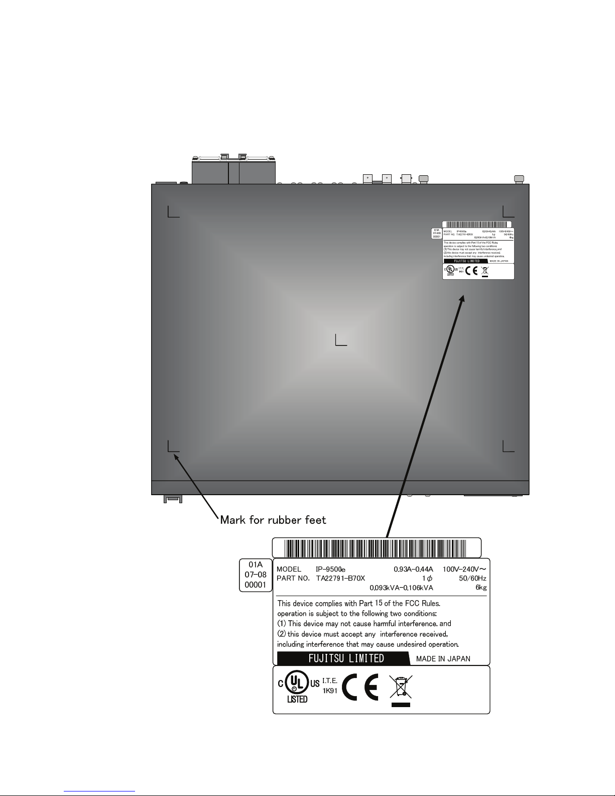
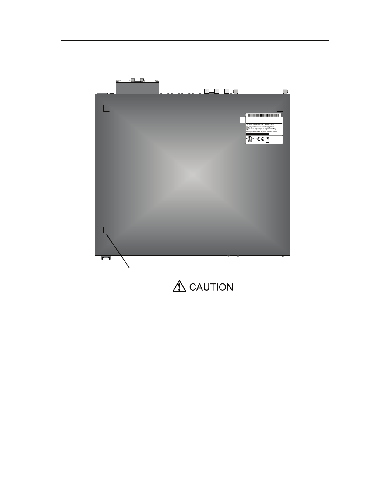
LABEL
The warning label shown below is affixed to
the device.
・ Never remove the label.
・ Be sure to check the label at the bottom of this device before coming to the power supply.
・ The following label is intended for users of the devices.
Page 12

IP-9500e
x
PRODUCT HANDLING PRECAUTIONS
Maintenance
Do not try to repair the device yourself. Contact a Fujitsu Service Center.
Read this manual thoroughly before attempting to operate the device.
If you have any questions, contact a Fujitsu Service Center.
If a problem occurs, contact a Fujitsu Service Center.
The Fujitsu Service Center will ask you to describe the problem, the lamp display status of
alarm LEDs and other details. Check the system for this information.
Connectable devices
Only devices that conform to the device interface specifications (see Appendix 2.3, "Device
Specifications") can be connected. Otherwise, if incompatible devices are connected, the result
may be personal injury and property damage.
Disposal
To dispose of the device, contact a Fujitsu Service Center, or request a specialist to take care its
disposal.
Modification and restoration
Do not use any device that has been modified or rebuilt with refurbished used parts. Doing so
may result in personal injury and property damage.
WARNING
CAUTION
Page 13

IP-9500e
I
CONTENTS
Chapter 1 Preparations.......................................................................... 1
1.1 Main Features ...................................................................................... 3
1.2 Components......................................................................................... 4
1.3 Basic Application Examples ................................................................. 5
1.4 Part Names .......................................................................................... 6
Chapter 2 Installation and Connection................................................. 9
2.1 Installation Conditions .........................................................................11
2.1.1 Environment conditions ............................................................11
2.1.2 Installation environment............................................................11
2.1.3 Air flow into and out from the device........................................ 14
2.1.4 Open space required around the device.................................. 15
2.2 Power Supply System Connections................................................. 16
2.2.1 Connection to ground .............................................................. 16
2.2.2 Connection to power source.................................................... 17
2.3 Audio and Video Device Connections.............................................. 20
2.3.1 Encoder ................................................................................... 20
2.3.2 Decoder ................................................................................... 22
2.4 Connection to Network ....................................................................... 24
2.5 Connection to RS-232C Device....................................................... 25
2.6 CF Card Insertion and Removal ......................................................... 26
2.7 Optional Card Slot .............................................................................. 27
Chapter 3 Operation Instructions ....................................................... 29
3.1 Power ON/OFF................................................................................... 31
3.1.1 Powering on............................................................................. 31
3.1.2 Powering off............................................................................. 31
3.2 Device Settings and Operation........................................................... 32
3.2.1 Maintenance page ................................................................... 34
3.2.2 Reboot ..................................................................................... 34
3.3 Operation Management...................................................................... 35
3.3.1 Settings.................................................................................... 35
3.3.2 Log .......................................................................................... 37
3.3.3 Software management............................................................. 39
3.4 Device Setting and Operation (Front Panel)....................................... 40
3.5 Operation Method and Page Transition ........................................... 41
3.6 Special Use of Cancel Key................................................................. 47
Chapter 4 Cable Specifications........................................................... 49
4.1 Installation Preparations..................................................................... 51
4.2 Cable and Connector Details.............................................................. 52
Page 14

IP-9500e
II
Chapter 5 Troubleshooting ..................................................................61
5.1 Help Information..................................................................................63
5.2 Alarm LED Lamp Is On ....................................................................... 65
5.3 Maintenance .......................................................................................66
5.3.1 Maintenance space .................................................................. 66
5.3.2 Change of maintenance parts (Maintenancer only).................. 67
Appendix..................................................................................................69
A.1 Appearance......................................................................................... 71
A.2 Basic Specifications ............................................................................73
A.2.1 External specifications..............................................................73
A.2.2 Environment specifications....................................................... 73
A.2.3 Function specifications .............................................................74
A.3 Preparations for Installation Work .......................................................80
A.3.1 Scope of installation work.........................................................80
A.3.2 Unpacking and device check....................................................80
A.3.3 Installation conditions ...............................................................80
A.3.4 Connecting external cables ......................................................80
A.4 Preparations for On-site Turn-up ...................................................... 81
Glossary and Index .................................................................................85
Glossary.......................................................................................................87
Index ............................................................................................................90
Page 15

Chapter 1 Preparations
This chapter describes the checks that are required before the start of IP-9500e
operation.
1.1 Main Features ············································································ 3
1.2 Components··············································································· 4
1.3 Basic Application Examples ·······················································5
1.4 Part Names ················································································ 6
CHAPTER 1
PREPARATIONS
Page 16

(This page is intentionally left blank)
Page 17
Chapter 1 Preparations
IP-9500e
3
1.1 Main Features
IP-9500e is the video transmission unit with the H.264 encoding technology which performs the high
compression ratio, and transmits the HD (High Definition) video signal in real time through even the
optical IP network like FTTH.
IP-9500e has an encoding function that encodes HD video signals from a HD camera or similar device
and distributes it across the network in real-time. Its decoding function decodes the encoded HD video
signal data received via the network and displays it on a monitor or other device.
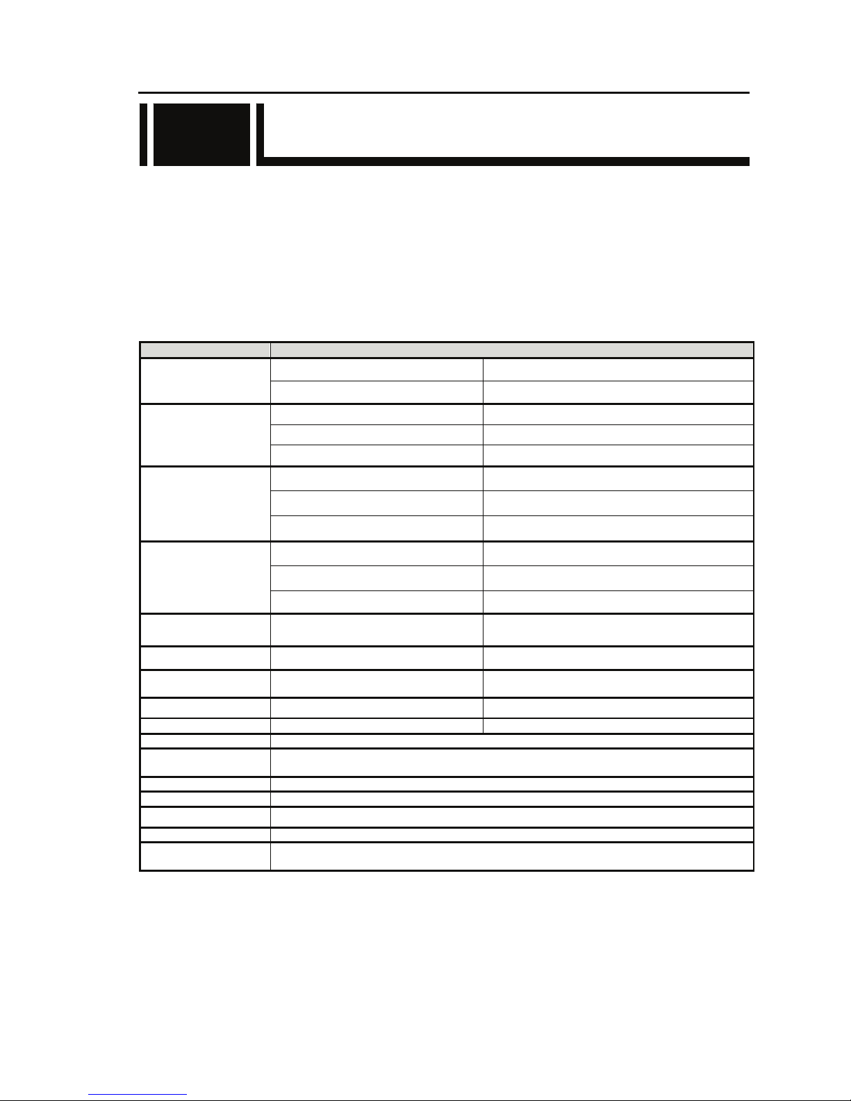
Main Features
Item Specifications
HD-SDI 1ch [BNC]
Video input
HDMI 1ch [HDMI]
HD-SDI 1ch [BNC]
HDMI 1ch [HDMI]
Video output
Analog Composite 1ch [BNC] NTSC/PAL
HD-SDI embedded 4ch [BNC], 2 stereo pairs
HDMI 2ch [HDMI]
Audio input
Analog balanced 600Ω 2ch [XLR 3pin], 1 stereo pair
HD-SDI embedded 4ch [BNC], 2 stereo pairs
HDMI 2ch [HDMI]
Audio output
Analog balanced 600Ω 2ch [XLR 3pin], 1 stereo pair
Reference clock input
Analog Composite 75Ω or
Component 75Ω
1ch [BNC]
Voice input/output Analog balanced 600Ω 1ch [RJ25]
Network LAN 2ch
[RJ45],
10BASE-T / 100BASE-TX / 1000BASE-T
Data input/output RS-232C 1ch [D-sub9-pin], male connector
CF CARD slot CF CARD 1 Data storage application
Installation conditions Indoor: On a desk, mounted in a rack
Dimensions
W: 425 H: 42 D: 350 (mm) Note: Excluding protrusions (i.e., not including feet)
W: 430 H: 45 D: 393 (mm) Note: Including FAN, etc
Cooling system Forced air cooling
Power supply 100-240VAC
Weight Maximum 6kg
Power consumption 90W (93VA) or less @ 100VAC
Temperature
Humidity
-10 to 55°C (No low temperature startup: -10 to -1°C)
20 to 90%RH (No condensing)
1.1
Page 18
Chapter 1 Preparations
IP-9500e
4
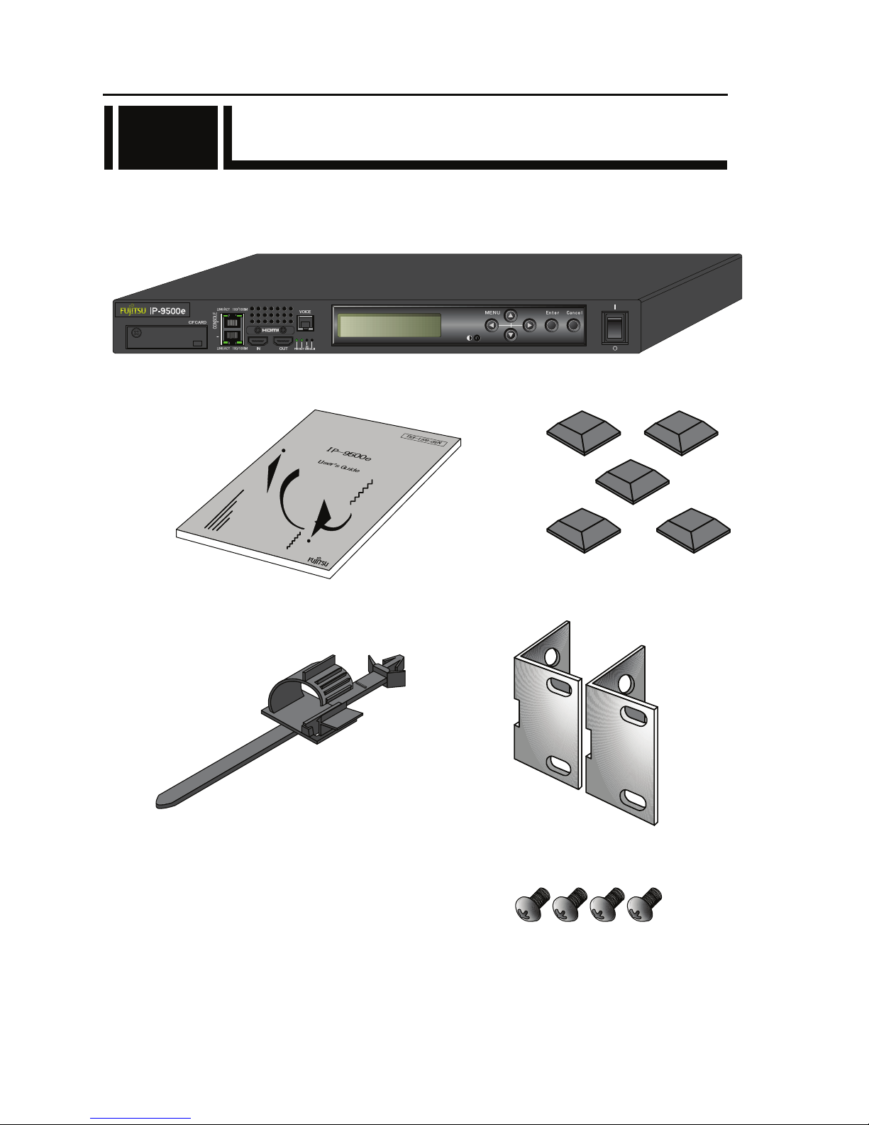
1.2 Components
The IP-9500e product package consists of the following components.
・ IP-9500e: 1 pc (cables separate order)
・ Instruction manual (this manual): ・ Feet: 5 pcs
・ Holder of power supply cable: 1 pc ・ Mounting kit on 19” rack: 2 pcs
・ Pan screw (M5): 4 pcs
(19” rack - Mounting kit)
LAN
1.2
Page 19
Chapter 1 Preparations
IP-9500e
5
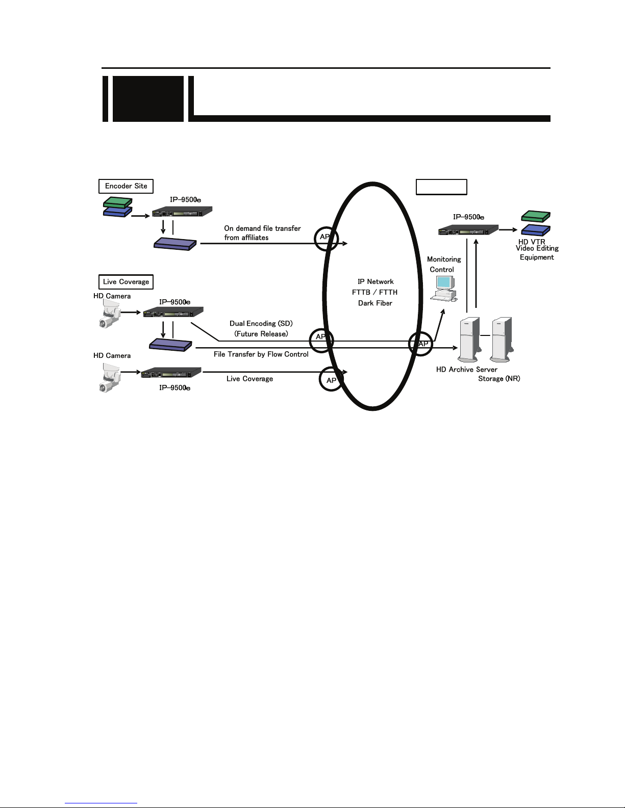
1.3 Basic Application Examples
Examples (system configuration) of use of IP-9500e are shown below.
1.3
HD
Decoder Site
Page 20
Chapter 1 Preparations
IP-9500e
6
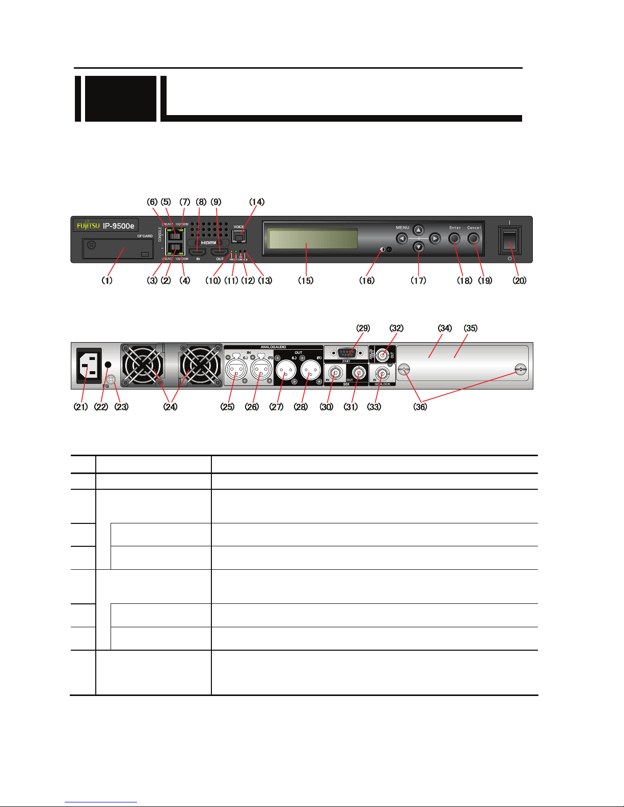
1.4 Part Names
This section gives the name and describes the function of individual parts of IP-9500e.
The diagrams below show the layout of parts on the outside of the device, and the table below lists
the name and describes the function of individual parts. Numbers in the diagrams correspond to
numbers in the table.
Figure Front panel
Figure Rear panel
Part names
No. Name Description
(1)
CF CARD slot
Slot in which a CompactFlash
@
card is inserted.
(2)
LAN port
(LAN)
Ethernet 10BASE-T/100BASE-TX /1000BASE-T communication port.
See Section 2.4, “Connection to a Network,” for an explanation on using this port.
See Section 4.2, “Cable and Connector Details,” for cable connection information.
(3)
Status LED
(LINK/ACT)
Indicates the status of LAN port.
For more information, see Table 5.3, “Details of LED Indications,” in Section 5.2.
(4)
Speed LED
(100/1000M)
Indicates the speed of LAN port.
For more information, see Table 5.3, “Details of LED Indications,” in Section 5.2.
(5)
CONSOLE port
(CONSOLE)
Ethernet 10BASE-T/100BASE-TX /1000BASE-T communication port
.
See Section 2.4, “Connection to a Network,” for an explanation on using this port.
See Section 4.2, “Cable and Connector Details,” for cable connection information.
(6)
Status LED
(LINK/ACT)
Indicates the status of console port.
For more information, see Table 5.3, “Details of LED Indications,” in Section 5.2.
(7)
Speed LED
(100/1000M)
Indicates the speed of console port.
For more information, see Table 5.3, “Details of LED Indications,” in Section 5.2.
(8)
HDMI input
(HDMI IN)
Digital HDMI video input terminal. 50Ω unbalanced.
See Section 2.3, “Audio and Video Device Connections,” for an explanation on
using this terminal. See Section 4.2, “Cable and Connector Details,” for cable
connection information.
1.4
LAN
Page 21

Chapter 1 Preparations
IP-9500e
7
No. Names Description
(9)
HDMI output
(HDMI OUT)
Digital HDMI video output terminal. 50Ω unbalanced.
See Section 2.3, “Audio and Video Device Connections,” for an explanation on
using this terminal. See Section 4.2, “Cable and Connector Details,” for cable
connection information.
(10)
Power LED (PWR) Turns on when the device is powered on.
(11)
Status LED
(RDY)
Turn on when IP-9500e power is on. For more information, see Table 5.3,
“Details of LED Indications,” in Section 5.2.
(12)
AV input status LED
(INDWN)
Audio/Video input setting status indicator and LED that indicates the input off
status during input setting. For more information, see Table 5.3, “Details of
LED Indications,” in Section 5.2.
(13)
Alarm LED
(ALM)
Turns on when IP-9500e operation is abnormal. For more information, see
Table 5.3, “Details of LED Indications,” in Section 5.2.
(14)
Voice input/output
(VOICE)
Voice communication (Intercom) port between IP-9500s.
See Section 2.3, “Audio and Video Device Connections,” for an explanation on
using this terminal. See Section 4.2, “Cable and Connector Details,” for cable
connection information.
(15) LCD panel Uses to set IP-9500e up and displays status. 2 lines x 20 characters.
(16) LCD brightness controller Adjusts the brightness of LCD panel.
(17)
Direction key
(△▽Y Z)
Uses to operate IP-9500e and check the status.
See Section 3.4, “Device Setting and Operation (Front Panel)” for more
explanation.
(18)
Enter key
(Enter)
Used to finalize the displayed data on the front panel.
See Section 3.4, “Device Setting and Operation (Front Panel)” for more
explanation.
(19)
Cancel key
(Cancel)
Used to cancel the displayed data on the front panel.
See Section 3.4, “Device Setting and Operation (Front Panel)” for more
explanation.
(20)
Power button Turns the device on and off.
(21)
Power inlet connector
(INPUT 100-240VAC)
Can be connected to a 100-240VAC commercial power supply by using power
card with a standard two-prong plug with ground.
See Section 2.2.2, “Connection to a Power Source,” for an explanation on using
this connector. See Section 4.2, “Cable and Connector Details,” for cable
connection information.
(22)
AC cord clamp hole
Hole to fix AC cord clamp.
See Section 2.2.2, “Power Supply System Connection” for more information.
(23)
FG terminal
(FG
)
Use for an FG connection to the device.
See Section 2.2.1, “Connection to ground,” for an explanation on using this
terminal.
(24)
FAN Maintenance-free FAN that cools the inside of the device.
(25)
(26)
Audio input
(ANALOG AUDIO IN)
(L), (R)
Balanced audio input terminal.
See Section 2.3, “Audio and Video Device Connections,” for an explanation on
using this terminal. See Section 4.2, “Cable and Connector Details,” for cable
connection information.
(27)
(28)
Audio output
(ANALOG AUDIO OUT)
(L), (R)
Balanced audio output terminal.
See Section 2.3, “Audio and Video Device Connections,” for an explanation on
using this terminal. See Section 4.2, “Cable and Connector Details,” for cable
connection information.
(29)
RS-232C port
(232C)
RS-232C data communication port.
See Section 2.5, “Connection to an RS-232C Device,” for an explanation on
using this pin. See Section 4.2, “Cable and Connector Details,” for cable
connection information.
Page 22

Chapter 1 Preparations
IP-9500e
8
No. Names Description
(30)
SDI video input
(SDI IN)
Digital HD-SDI video input terminal. 75Ω unbalanced.
See Section 2.3, “Audio and Video Device Connections,” for an explanation on
using this terminal. See Section 4.2, “Cable and Connector Details,” for cable
connection information.
(31)
SDI video output
(SDI OUT)
Digital HD-SDI video output terminal. 75Ω unbalanced.
See Section 2.3, “Audio and Video Device Connections,” for an explanation on
using this terminal. See Section 4.2, “Cable and Connector Details,” for cable
connection information.
(32)
Video output
(ANALOG VIDEO OUT)
Analog video output terminal. 75Ω unbalanced.
See section 2.3, “Audio and Video Device Connections,” for an explanation on
using this terminal. See Section 4.2, “Cable and Connector Details,” for cable
connection information.
(33)
Reference clock signal
input
(GENLOCK IN)
External clock signal input terminal. 75Ω unbalanced.
See Section 2.3, “Audio and Video Device Connections,” for an explanation on
using this terminal. See Section 4.2, “Cable and Connector Details,” for cable
connection information.
(34)
Optional card slot
Optional card slot.
(35)
Blank panel
Remove when the optional card is equipped. See Section 2.7, “Optional card
insertion” for removing or insertion of the optional card.
(36)
Screws
Screws to fix the optional card. See Section 2.8, “Optional card insertion” for
removing or insertion of the optional card.
Page 23

Chapter 2 Installation and Connection
This chapter describes conditions for IP-9500e installation and explains how to
connect it to peripheral devices.
2.1 Installation Conditions······························································ 11
2.2 Power Supply System Connections ······································ 16
2.3 Audio and Video Device Connections ··································· 20
2.4 Connection to Network····························································· 24
2.5 Connection to RS-232C Device············································· 25
2.6 CF Card Insertion and Removal··············································· 26
2.7 Optional Card Slot···································································· 27
CHAPTER 2
INSTALLATION AND
CONNECTION
Page 24

Possibility of serious injury
The power cord and other cables connected to IP-9500e may become
entangled with someone walking close to them, possibly leading to serious
injury and property damage. Clamp the cables to the rack or floor.
Page 25
Chapter 2 Installation and Connection
IP-9500e
11
2.1 Installation Conditions
This section describes the installation environment, air flow into and out from the device, and the
requirement for open space around the device.
2.1.1 Environment conditions
Ensure that installation site conditions do not exceed 55°C. Under this condition, IP-9500e can
operate in the multiple pile. Otherwise, the operating environment may damage and shorten the
product life of IP-9500e noticeably.
2.1.2 Installation environment
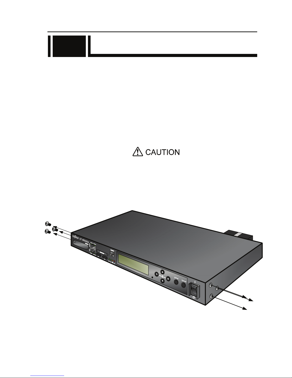
1. 19” rack mounting
Using the mounting kit, it is possible to mount on 19” rack complied EAI standard (1U size).
The mounting kit attached must be used to install. When the installation
is unstable, the serious accident may be caused.
(1) Check all cables disconnected.
(2) Screw out six pan screws (three at right side and three at left side) to install the rack mounting
kit.
2.1
Page 26
Chapter 2 Installation and Connection
IP-9500e
12
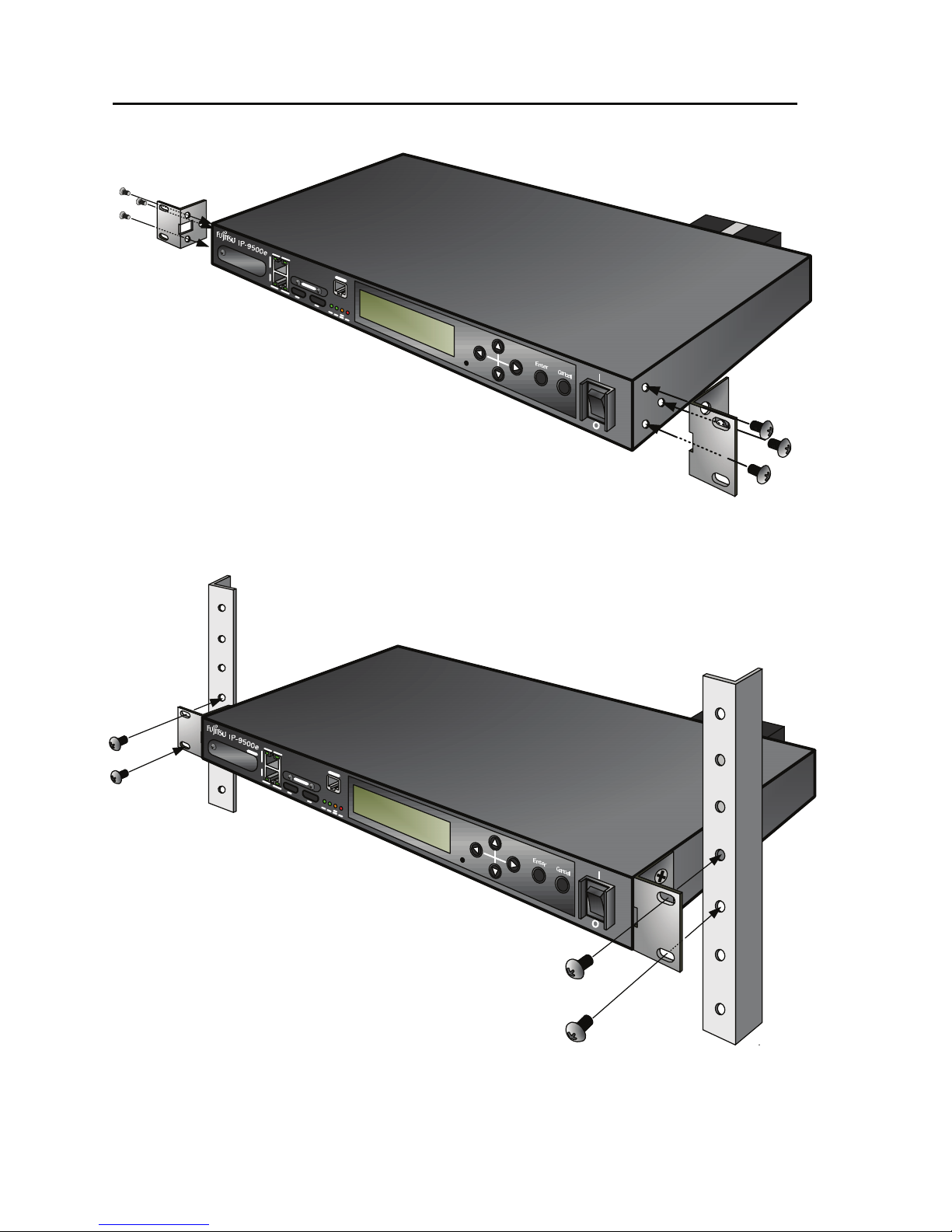
(3) Install the rack mounting kit on 19” rack using six same screws.
(4) Install IP-9500e on 19” rack using the four pan screws (M5) attached.
Page 27
Chapter 2 Installation and Connection
IP-9500e
13
2. Desk-top installation
Install IP-9500e referring Section 2.1.3, “Air flow into and out from the device” and Section
2.1.4, “Open space required around the device” after sticking the five rubber feet (Rack
mounting kit is not required).
Safety installation instruction:
1) Multiple pile
The maximum 5 IP-9500e can be piled under the environment condition
specified. Please install considering the maintenance-ability. When
IP-9500e are piled, please fix them to avoid to fall (Do not cover the air
intake.). See Section 2.1.4, “Open space required around the device” for
the installation space.
2) When IP-9500e is installed in a closed or multi-unit rack, the operating
ambient temperature inside of the rack environment may be greater
than room ambient. Therefore, the consideration should be given to
operate in the environment compatible with the specifications in
Appendix 2.2 “Environment Specifications.”
- The consideration for adjustment of the air condition like air
circulation should be given to prevent the internal rack ambient
from exceeding the maximum operating ambient temperature of
IP-9550e.
- The maximum operating ambient temperature for IP-9500e: 55°C.
Mark for rubber feet
MODEL
PART NO.
IP-9500e
TA22791-B70X
MADE IN JAPAN
0.93A-0.44A
1φ
100V-240V~
50/60Hz
6kg
FUJITSU LIMITED
01A
07-08
00001
0.093kVA-0.106kVA
1K91
I T E
Page 28

Chapter 2 Installation and Connection
IP-9500e
14
3) The installation of IP-9500e in a rack should be such that the amount of
airflow required for safe operation of IP-9500e is not compromised.
- IP-9500e has ventilation opening at the left and rear side.
- Do not cover or close these ventilation openings to prevent
overheating.
4) The mounting of IP-9500e in a rack should be such that a hazardous
condition in not archived due to uneven mechanical loading. To keep
stability of the entire rack, please fix the rack to wall or floor by
suitable means.
- Be careful about injury during installation of IP-9500e into rack.
- Do not install IP-9500e into your rack where IP-9500e mau make
the entire rack unstable.
- The weight of IP-9500e with the maximum configuration: 6 kg
5) If IP-9500e is supplied from the power strip or the service outlet of
other units, it may overload the power supply cord of the power strip or
other units.
- Confirm that the current rating of the power strip or the service
outlet exceeds the combined ratings of all equipment is supplying.
- The electrical rating of IP-9500e: Rated 100-240 VAC, 0.93-0.44 A,
50/60 Hz, 1 phase.
6) The reliable earthing of the rack-mounted equipment must be
maintained. The particular attention should be given to supply
connections other than direct connections to the branch circuit (e.g., use
of the power strips or the power distribution unit).
Note: The high leakage current may flow through the power strip
earthing conductor if all power supply cords of IP-9500e are connected
to one power strip. The earth connection is essential before connecting
supply. If the power strip is not directly connected to the branch circuit,
the power strip which has the industrial type attachment plug should be
used.
7) For installing, IP-9500e shall be installed near the wall-outlet and the
wall-outlet shall be easily accessible.
2.1.3 Air flow into and out from the device
IP-9500e is forced air cooled. Be sure not to block the air intake/exhaust vents. Provide an
adequate amount of space around the vents.
Page 29
Chapter 2 Installation and Connection
IP-9500e
15
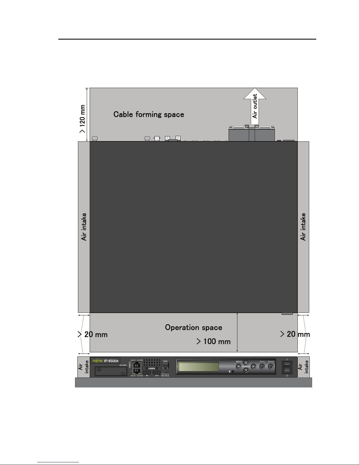
2.1.4 Open space required around the device
Provide the indicated (parts with hatched area) below, cable forming space, operation space and
air intake/exhaust.
For the information of maintenance space, see Section 5.3.1, “Maintenance space.”
LAN
Page 30
Chapter 2 Installation and Connection
IP-9500e
16
2.2 Power Supply System
Connections
This section explains ground and power-source connections.
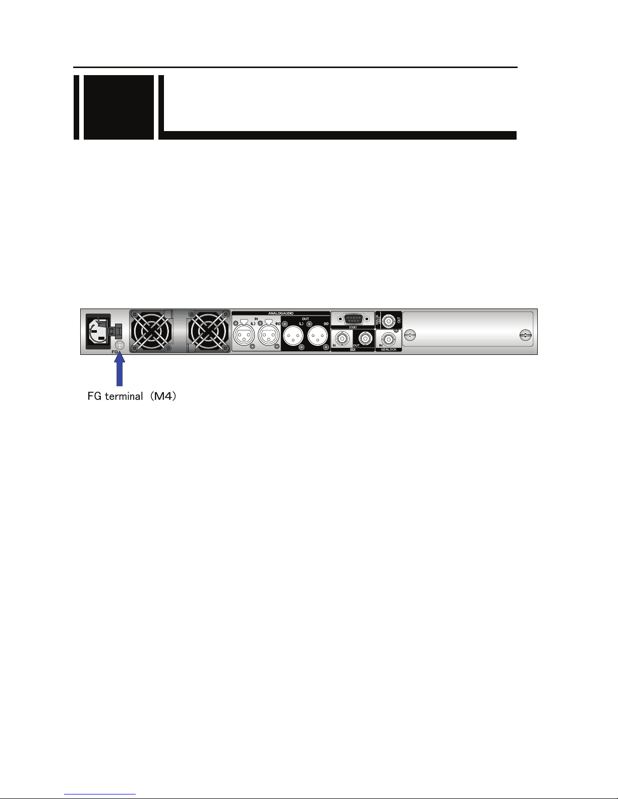
2.2.1 Connection to ground
Use a power cord with the standard two-prong plug with ground wire for FG and external ground
connections.
When not using a power cord with a ground wire, connect the FG terminal to an external ground.
The FG terminal has an M4 screw that comes with a plastic washer. To connect the FG wire,
remove this washer.
Figure Connection to ground
2.2
Page 31

Chapter 2 Installation and Connection
IP-9500e
17
2.2.2 Connection to power source
IP-9500e operation requires a power supply of 100-240 VAC. Insert the power cord with the
standard two-prong plug with ground into the inlet connector.
The power cord is not supplied with the device. Procure it separately.
Figure Power cord connection
AC cord clamp
Insert the AC cord clamp into the AC cord clamp hole and fix the power cord as shown in
figure above. When remove the AC cord clamp, screw out and remove it with the mounting
kit.
Page 32

Chapter 2 Installation and Connection
IP-9500e
18
or
or
or
or
or
or
USABLE DETACHABLE POWER SUPPLY CORD SET
MODEL Input Connector Cord Attachment Plug cap
North
America
<*1>
<*2>
100120V
IEC C-13
Rated 13A, 125V
UL, CSA Approved
Type SJT, No.16 AWG Min.
3-Conductors
(Single phase;2-current carrying
conductors & ground)
UL, CSA Approved
NEMA (5-15P)
parallel blade
Rated 13A, 125V
UL, CSA Approved
200240V
IEC C-13
Rated 15A, 250V
UL, CSA Approved
Type SJT, No.14 AWG Min.
3-Conductors
(Single phase; 2-current carrying
conductors & ground)
UL, CSA Approved
NEMA (6-15P)
tandem blade
Rated 15 A, 250 V
UL, CSA Approved
Europe
<*2>
100240V
IEC C-13
Rated 10A, 250V
<*1>
CENELEC OC
3X1.0 square mm<*1>
<HAR>
Rated 10 A, 250 V
<*1>
Australia
100240V
IEC C-13
Rated 10A,
250V
Cable: AS OD 3 X1.0 square mm
e.g.
Rated 10 A, 250 V
U.K
<*2>
100240V
IEC C-13
Rated 10A,
250V
BS OC 3 X1.00 square mm Rated 10 A. 250 V
IEC C-13
Rated 13A,
125V
Type HVCTF cross section area
1.25 square mm
3-Conductors
(Single phase;2-current
carrying conductors & ground)
NEMA (5-15P)
parallel blade
Rated 13 A, 125 V
Japan
100V
METI Approved
or <PSE>
METI Approved
or <PSE>
METI Approved
or <PSE>
220V
(Class I)
IEC 60320-1
(IEC C-13)
Rated 12A, 250V
Comply with KSC3304.
Type VCTF cross section area 1.25
(0.50 or 1.00 or 2.00) square mm
3-Conductors
(Single phase;2-current
carrying conductors & ground)
Comply with KSC8305.
Rated 12A, 250V
Korea
220V
(Class II)
IEC 60320-1
(IEC C-13)
Rated 3A, 250V
Comply with KSC3304.
Type VCTFK cross section area
1.25 (0.50 or 0.75 or 1.00 or 2.00)
square mm
2-Conductors
Comply with KSC8305.
Rated 12A, 250V
Note: *l. Be sure that the detachable proper Supply cord has the approval of the
appropriate safety agencies of the country where the equipment will be used.
*2. Cable length of above Power Supply cord shall be shorter than 4.5 m.
or
ASA
PS
E
PS
E
PS
E
Page 33

Chapter 2 Installation and Connection
IP-9500e
19
CERTIFICATION MARKING
Country Agency Certification Mark Country Agency Certification Mark
Austria OVE
Italy IMQ
Belgium CEBEC
Norway NEMKO
Denmark DEMKO
Spain AEE
Finland FEI
Sweden SEMKO
France UTE
Switzerland SEV
Germany VDE
Possibility of electric shock, fire, and damage to the device
Always observe the precautions given below.
This indicates a hazardous situation that could lead to electric shock, fire, or
damage to the device.
Always connect the power cord to a power receptacle for the standard
two-prong plug with ground.
Use a power receptacle with a capacity of 1A or more. When using a power
extension cable, be sure that the total power consumption of all devices
connected to the cable does not exceed the rated capacity of the cable. If the
power receptacle capacity is low, or power consumption exceeds the rated value,
the power cord or power wiring may overheat and start a fire.
Possibility of damage to the device
Do not turn on the device until connection of peripheral devices is completed.
Otherwise, the device may be damaged.
100-240 VAC
Using a power cord with the standard two-prong plug with ground, connect
IP-9500e to 100-240 VAC outlet.
Provide a power receptacle for the standard two-prong plug with ground.
V
DE
Page 34

Chapter 2 Installation and Connection
IP-9500e
20
2.3 Audio and Video Device
Connections
2.3.1 Encoder
For audio and video encoding, there are two digital video, one digital audio and two analog audio
terminals to connect audio and video output device.
Digital video input
Connect to SDI IN terminal on the rear panel of IP-9500e using coaxial cable with BNC
connector and input HD-SDI signal. The signal is terminated in 75Ω. The HD signal input is
output from SDI OUT and ANALOG VIDEO OUT (NTSC after downconverted) terminals to
monitor simultaneously.
Digital and analog audio input
Connect to ANALOG AUDIO IN (L), (R) on the rear panel of IP-9500e using the cable with
XLR connector. The impedance is 600Ω balanced. Inputting a signal outside of the rated
value will cause a problem in terms of audio level and noise. To input mono signal, connect
the audio device to ANALOG AUDIO IN (L) terminal. The HD-SDI embedded audio is
supported for the digital audio too.
The figure below shows how to connect the digital and analog audio/video cables. See the next
page for the connection of HDMI and voice communication cables.
For details about connectors and cables, see Section 4.2, “Cable and Connector
Details.” For electrical specifications, see Appendix 2.3, “Function Specifications.”
Figure Audio and video output device connections
2.3
NOTE:
Page 35

Chapter 2 Installation and Connection
IP-9500e
21
For HDMI input, there is one HDMI terminal to connect the video and audio output device.
Connect to HDMI IN on the front panel of IP-9500e using the HDMI cable. The signal is terminated
in 50Ω.
For voice communication between IP-9500e, there is one voice terminal to connect the voice
communication device (e.g., intercom).
Connect to VOICE terminal on the front panel of IP-9500e using the dedicated adaptor cable with the
bidirectional voice communication terminal (RJ25 – XLR). The impedance is terminated in 600Ω.
There are two types of the cables. Procure the appropriate type separately because this cable is not
attached to IP-9500e. For more information, see Section 4.2, "Cable and Connector Details."
For details of the connector and cable, see Section 4.2, "Cable and Connector
Details." For the electric specifications, see Appendix 2.3, Function Specifications."
LINK/ACT
100/1000M
LINK/ACT
100/1000M
LINK/ACT
100/1000M
LINK/ACT
100/1000M
PUSH
Audio & Video
Output Device
Audio Input
Device
OR
Type 1 Type 2
PUSH
Audio Input
Device
Audio Output
Device
NOTE:
Page 36

Chapter 2 Installation and Connection
IP-9500e
22
2.3.2 Decoder
For audio and video decoding, there are two digital vide, one analog video, one digital audio and
two analog audio terminals to connect and audio and video input device.
Digital video output
Connect to SDI OUT on the rear panel of IP-9500e using coaxial cable with BNC connector
and output HD-SDI signal.
Analog video output
Connect to ANALOG VIDEO OUT on the rear panel of IP-9500e using coaxial cable with
BNC connector and output NTSC or PAL signal.
Digital audio output
The HD-SDI embedded audio is supported.
Analog audio output
Connect to ANALOG AUDIO OUT (L), (R) on the rear panel of IP-9500e using the cable
with XLR connector. The impedance is 600Ω balanced. Inputting a signal outside the rated
value will cause a problem in terms of audio level and noise. To output mono signals,
connect the audio device to the AUDIO OUT (L) terminal.
In addition, the synchronization input is available. Connect to GENLOCK IN on the rear panel
of IP-9500e using the coaxial cable with BNC connector. The signal is terminated in 75Ω.
The figure below shows how to connect the digital and analog audio/video and the reference clock
cables. See the next page for the connection of HDMI and voice communication cables.
For details about connectors and cables, see Section 4.2, “Cable and Connector Details.”
For electrical specifications, see Appendix 2.3, “Function Specifications.”
Figure Audio and video input device connections
NOTE:
Page 37

Chapter 2 Installation and Connection
IP-9500e
23
For HDMI output, there is one HDMI terminal to connect the video and audio input device.
Connect to HDMI OUT on the front panel of IP-9500e using the HDMI cable.
For voice communication between IP-9500e, there is one voice terminal to connect the voice
communication device (e.g., intercom).
Connect to VOICE terminal on the front panel of IP-9500e using the dedicated adaptor cable with the
bidirectional voice communication terminal (RJ25 – XLR). The impedance is terminated in 600Ω.
There are two types of the cables. Procure the appropriate type separately because this cable is not
attached to IP-9500e. For more information, see Section 4.2, "Cable and Connector Details."
For details of the connector and cable, see Section 4.2, "Cable and Connector
Details." For the electric specifications, see Appendix 2.3, Function Specifications."
NOTE:
Page 38

Chapter 2 Installation and Connection
IP-9500e
24
2.4 Connection to Network
To connect IP-9500e to a LAN device, connect the LAN device to the LAN communication port
[CONSOLE/LAN] of IP-9500e using a LAN cable (UTP cable). The LAN communication port
specification of IP-9500e is 10BASE-T/100BASE-TX /1000BASE-T for CONSOLE and LAN.
The figure below shows the connection method.
For details about connectors and cables, see Section 4.2, “Cable and Connector Details.”
For electrical specifications, see Appendix 2.3, “Function Specifications.”
Figure Connection to a network
Please do not provision the IP address below.
LAN/Console ports;
・ IP address commonly unused(0.0.0.0,255.255.255.255,etc…)
・ Loop back address (127.xxx.xxx.xxx)
・ Class D and Class E addresses
・ IP address already used
Console port only;
・IP address (169.254.xxx.xxx) used when LAN port cannot obtain IP address
normally from PPPoE/DHCP server.
For more information, see IP-9500e Software User’s Guide.
2.4
CAUTION
NOTE:
LINK/ACT
100/1000M
LAN
LINK/ACT
100/1000M
HUB, Router, etc
NETWORK/CONSOLE
CONSOLE
Client PC
Page 39

Chapter 2 Installation and Connection
IP-9500e
25
2.5 Connection to RS-232C
Device
The [232C] connector of IP-9500e is the RS-232C communication terminal. The terminal of
IP-9500e is the D-sub 9 pins (male) and the specification is DTE. Use a cross connection or straight
cable corresponding to the connected device. See Section 4.2, “Cable and Connector Details.”
The figure below shows the connection method.
For details about connectors and cables, see Section 4.2, “Cable and Connector Details.”
For electrical specifications, see Appendix 2.3, “Function Specifications.”
Figure Connection to RS-232C input/output device
2.5
PUSH
PUSH
Data communication
device
D-sub 9 pin female
NOTE:
Page 40

Chapter 2 Installation and Connection
IP-9500e
26
2.6 CF Card Insertion and Removal
In order to insert the CF card, the front cover of IP-9500e must be opened by screwing out the cover.
No storage card is supplied with IP-9500e. It can be procured separately, depending on the system.
The CF card removal procedure is shown below.
Please turn off the power to insert or remove the CF card.
Please contact Fujitsu office what type of CF card is available to use.
2.6
Page 41

Chapter 2 Installation and Connection
IP-9500e
27
2.7 Optional Card Slot
The install procedure of optional card is as follows.
Please turn off the power of IP-9500e when the optional card is inserted or removed.
Otherwise, it may cause the serious damage to the device or injury.
2.7
WARNING
Page 42

Chapter 2 Installation and Connection
IP-9500e
28
(This page is intentionally left blank)
Page 43

Chapter 3 Operation Instructions
This section explains how to power on/off, setup and operate the device.
3.1 Power ON/OFF ········································································31
3.2 Device Settings and Operation ················································32
3.3 Operation Management ···························································35
3.4 Device Setting and Operation (Front Panel) ····························40
3.5 Operation Method and Page Transition································· 41
3.6 Special Use of Cancel Key······················································· 47
CHAPTER 3
OPERATION INSTRUCTIONS
Page 44

IP-9500e can be used to provide a variety of services using different types of
installed software.
Always install the appropriate software for IP-9500e.
Page 45

Chapter 3 Operation instructions
IP-9500e
31
3.1 Power ON/OFF
This section explains how to power on/off the IP-9500e.
3.1.1 Powering on
When the power button on the front panel is set to the [ | ] position, the PWR LED turns on.
When IP-9500e completes preparations for operation, the RDY LED turns on.
3.1.2 Powering off
When the power button on the rear panel is set to the [O] position, the device is powered off and
the PWR LED turns off
3.1
Page 46

Chapter 3 Operation instructions
IP-9500e
32
3.2 Device Settings and Operation
■Setup Procedure
The setup procedure is shown below.
See Software User’s Guide for the procedure of the software installation and the each setting.
■Web browser recommended
The recommended web browser is as follow.
- Internet Explorer 6.0 SP2 or later
3.2
Page 47

Chapter 3 Operation instructions
IP-9500e
33
■ Basic functions of IP-9500e Web setup pages
The settings page at shipment from the factory is shown below:
Setup page at shipment from the factory (initial page)
Page 48

Chapter 3 Operation instructions
IP-9500e
34
This section briefly explains the basic functions of the setup pages.
3.2.1 Maintenance page
Clicking the Settings, Log or Software management menu in the left frame of the browser displays
the corresponding device setting page so that you can set or display items.
3.2.2 Reboot
Clicking the button displayed in the left frame of the browser reboots the device. When
you click the button, the following dialog box shown below appears for confirmation. Click OK to
reboot.
Page 49

Chapter 3 Operation instructions
IP-9500e
35
3.3 Operation Management
3.3.1 Settings
On the PC Web browser, specify the IP address of IP-9500e (LAN: 10.0.0.1, CONSOLE:
192.168.255.253) [example: http://10.0.0.1/ (LAN), http://192.168.255.253/ (CONSOLE)] to set up a
connection to the http server of the IP-9500e.
When using http://10.0.0.1/ for connection, set the PC IP address and subnet mask as follows:
- IP address : 10.xxx.xxx.xxx
(xxx is a number from 0 to 255, excluding 10.0.0.0, 10.0.0.1, and 10.255.255.255.)
[Example: 10.0.0.2]
- Subnet mask : 255.0.0.0
The page shown below first appears (Initial page at power-on immediately after shipment from the
factory). The IP addresses and subnet masks set for the IP-9500e on the LAN and CONSOLE, and
the gateway setting are displayed.
3.3
Page 50

Chapter 3 Operation instructions
IP-9500e
36
The items in the Settings window are listed in the table below:
Item Explanation
LAN IP address Displays the IP address on LAN.
Default: 10.0.0.1
LAN Subnet mask Displays the subnet mask on LAN.
Default: 255.0.0.0
Gateway Displays the gateway address.
Default: 0.0.0.0
CONSOLE IP address Displays the IP address on CONSOLE.
Default: 192.168.255.253
CONSOLE Subnet mask Displays the subnet mask on CONSOLE.
Default: 255.255.255.252
When you operate the IP-9500e with the default settings after shipment from the
factory, disconnect the IP-9500e from your network. Connect it to the setting
terminal via a Hub or directly. Install the software in the setting terminal, and
then set up the IP-9500e to meet the requirements for your network and then
connect the IP-9500e to the network. If you connect the IP-9500e to your
network with the default settings, an unexpected problem may be caused with
your network.
Page 51

Chapter 3 Operation instructions
IP-9500e
37
3.3.2 Log
Click Log in the left frame of the browser to display the log information page in the right frame of
the browser, where you can check alarm log information on the IP-9500e.
Clicking in the right frame deletes all log information.
* Up to 1,000 log items can be saved. Log items exceeding 1,000 items overwrite existing items
beginning with the chronologically oldest item. (Ten pages of log information, 100 items per page,
are saved.)
For details of the alarm log information, see the alarm code list on the next page. Note that
messages may be changed after installation of each type of software. For details, see IP-9500e
Software User's Guide.
Page 52

Chapter 3 Operation instructions
IP-9500e
38
Alarm codes
Error Code. Error information Description
0001 Boot (Power On) Normally started by the power button
0002 Boot (Reset) Normally started by reboot
0006 Software update Software updated
0007 Boot (Restart) Restarted due to a CPU error
0008 Boot (Others) Restarted due to a software error
0009 Shutdown Shutdown by LCD operation
000A RTC initialization RTC battery backup failure
000B CF card initialization CF card formatting error
000C Configuration update Configuration data updated
L001 LINK error(LAN) Disconnected from network equipment
L002 LINK error (CONSOLE) Disconnected from network equipment
L006 Time server synchronization failure Time synchronization with the time server failed
L009 DHCP connection failure Disconnection recognized by DHCP
L00A PPPoE connection failure Disconnection recognized by PPPoE
L00C IP address collision Collision between IP addresses on LAN and CONSOLE
L00E DHCP connection update IP address changed during DHCP connection
L00F PPPoE connection update IP address changed during PPPoE connection
I001 HD-SDI input down HD-SDI input signal not detected
I002 HDMI input down HDMI input signal not detected
I005 DVB-ASII input down DVB-ASI input signal not detected
I006 Reference clock input down GENLOCK signal not input
I011 Video synchronization error HD-SDI signal synchronization failed
I015 DVB-ASI synchronization failure DVB-ASI signal synchronization failed
I016 Reference clock synchronization failure GENLOCK input PLL synchronization failed
E001 Power error (*1) Power failure occurred
E003 Temperature error occurrence (*5) Abnormal temperature (shutdown processing started)
E00A Flash ROM check sum error (*1) Invalid data set in built-in Flash ROM
E010 FAN1 error (*2) FAN1 failed (low speed) or stopped
E011 FAN2 error (*2) FAN2 failed (low speed) or stopped
E013 Temperature warning (*2) Temperature alarm caused (warning only)
E082 CODEC1 error (*4) HD CODEC LSI error occurred
E083 CODEC2 error (*4) SD CODEC LSI error occurred
E084 CF card access error (*3) Access to the CF card failed
E085 CF card power error (*3) Over current to the CF card occurred
E08B SUBCPU 1 error (*4) SUBCPU 1 error occurred
E08C SUBCPU 2 error (*4) SUBCPU 2 error occurred
E08E Clock error (*1) Clock error or disconnection occurred
E08F Memory error (*1) SDRAM memory check error occurred
E090 Downconversion error (*6) Video Scalar error occurred
E091 Intercom error (*4) Intercom error occurred
E092 Version mismatch (*3) Version mismatch between hardware and software
E0A1 Optional card error (*3) Optional card failure
E0A4 Optional card (Unequipped) (*7) Optional card unequipped
"*" is marked on the left side of an error code for which an alarm recovery has occurred.
*1 After an alarm occurs, the ALM LED remains on. The device needs to be rebooted to turn off the ALM LED.
*2 The ALM LED blinks while an alarm is active. The LED goes off when the alarm cause is recovered.
*3 After occurrence of this error, the ALM LED remains to blink.
*4 After occurrence of this error, the operation is retired for recovery. If the retry for recovery is unsuccessful,
the ALM LED remains on. The device needs to be rebooted to turn off the ALM LED.
*5 If an extreme temperature is detected, all LEDs except LINK/ACT, 100/1000 go on. The device needs to be
rebooted to turn off the LEDs.
*6 The ALM LED is on while this alarm is active. The LED goes off when the error cause is recovered.
*7 The ALM LED blinks on while this alarm is active. The LED goes off when the error cause is recovered.
Page 53

Chapter 3 Operation instructions
IP-9500e
39
3.3.3 Software management
Click Software management in the left frame of the browser screen to display the software
management page in the right frame of the browser screen, where you can install software or restore,
save, or delete configuration data.
■Software
Specify an update file and enter the license key, and then click the
button to start
installing the software.
■Configuration (configuration data)
●Restoring all the configuration data
Specify the file containing the configuration data and then click the
button to restore
all the configuration data saved in the past.
●Saving all the configuration data
All the configuration data currently stored on the device can be saved to a PC by clicking the
button.
●Deleting all the configuration data
Clicking the
button deletes all the configuration data currently stored on the device.
Information such as IP addresses is also reset to the initial values with which the device was shipped
from the factory.
Changing (restoring or deleting) the configuration data, in some cases, changes IP
addresses, subnet masks, and the gateway address. Be careful because doing this may
cause an unexpected problem with your network.
NOTE:
Page 54

Chapter 3 Operation instructions
IP-9500e
40
3.4 Device Setting and Operation
(Front Panel)
The IP-9500e has six control keys: [U], [V], [Y], [Z], [Enter] and [Cancel]. Use these keys for
making settings.
The LCD panel displays of two lines, 20 characters per line.
Front Control Pane;
■Function description of each key
Functions of [U] and [V] keys
- Each key changes the menu items or setting items displayed on the LCD panel.
- The displayed item changes each time either key is pressed. [U] and [V] change items in
the opposite direction.
Functions of [Y] and [Z] keys
- Each key moves the cursor displayed on the LCD panel to the left or right.
- The cursor moves one column each time either key is pressed.
[Enter] key
- Pressing the [Enter] key while the maintenance initial page is displayed proceeds to the
maintenance menu page.
- Pressing the [Enter] key on the maintenance menu page allows you to make settings for status
display and shutdown.
[Cancel] key
- Pressing the [Cancel] key while the maintenance menu page is displayed proceeds to the
maintenance initial page. Pressing the [Cancel] key on the setting item selection page returns to
the page displayed immediately before you pressed the [Enter] key.
Other
- If you do not make any key input for 30 seconds on any page, the LCD panel backlight goes
off.
- If you do not make any key input for 60 seconds on any page, the current page proceeds to the
maintenance initial page.
3.4
Page 55

Chapter 3 Operation instructions
IP-9500e
41
3.5 Operation Method and Page
Transition
This section explains page transition on the LCD panel before application software is installed. For
information on the operation procedure for each function after software is installed, see the software
user's guide.
- IP-9500e startup (maintenance initial page)
Status
No.
Page status Description
Key operation
/Conditions
Transition
to
0
● Power-on
Maintenance initial page
(Initial screen)
Nothing is displayed on the LCD panel
for about 15 seconds from when the
power to IP-9500e is turned on to when
the RDY LED starts blinking in yellow.
After this, the message "Maintenance
Booting => Initializing..." appears and,
about one minute later, IP-9500e
initialization is finished and the RDY
LED at the front of the IP-9500e goes on.
Simultaneously, the maintenance initial
page as shown in the figure on the left is
displayed. (The figure on the left is a
display example.)
1
Press [Enter]
2-1
Press [Cancel]
-----
Press [△]
-----
Press [▽]
-----
Press [Y]
-----
1
●Maintenance initial page
The current software version is displayed
on line 1.
When the factory shipment setting is
effective, "Maintenance Vxxlxx" is
displayed. "xx" in the left figure
indicates the current version.
Configuration data is displayed on line 2.
When the factory shipment setting is
effective, "Configure#1" is displayed.
If the power is turned on with the
[Cancel] key pressed, "---" is displayed
on line 2. For more information, see
Section 3.6, "Special Use of the Cancel
Key."
Press [Z]
-----
3.5
(Blank)
IP-9500 VxxLxxx
Maintenance Booting
Maintenance VxxLxx
Configure#1
IP-9500 VxxLxxx
Initializing...
Maintenance VxxLxx
Configure#1
Page 56

Chapter 3 Operation instructions
IP-9500e
42
- Maintenance menu
Press [Enter] 3-1
Press [Cancel] 1
Press [△] 2-2
Press [▽] 2-2
Press [Y] -----
2-1
●Maintenance menu page 1
Pressing the Enter key while the initial
page of the maintenance menu is
displayed proceeds to this page.
This menu displays various settings on
the LAN or CONSOLE side.
Press [Z] -----
Press [Enter] 6-1
Press [Cancel] 1
Press [△] 2-1
Press [▽] 2-1
2-2
●Maintenance menu page 2
This menu is used to put the IP-9500e in
the state in which it can be turned off or
rebooted.
Press [Z] -----
- Status menu page
Status
No.
Page status Description
Key operation
/Conditions
Transition
to
Press[Enter] 4-1
Press [Cancel] 2-1
Press [△] 3-2
Press [▽] 3-2
Press [Y] -----
3-1
●Status menu page 1
Pressing the Enter key while the
Maintenance menu page 1 is displayed
proceeds to this page.
Pressing the Enter key at this page displays
the settings on the LAN side.
Press [Z] -----
Press [Enter] 5-1
Press [Cancel] 2-1
Press [△] 3-1
Press [▽] 3-1
Press [Y] -----
3-2
●Status menu page 2
Pressing the Enter key displays the settings
on the console side.
Press [Z] -----
Maintenance
1>Status
Maintenance
2>Shutdown
Status
2>Console Status
Status
1>LAN Status
Page 57

Chapter 3 Operation instructions
IP-9500e
43
- Status menu LAN
Status
No.
Page status Description
Key operation
/Conditions
Transition
to
Press [Enter] -----
Press [Cancel] 3-1
Press [△] 4-6
Press [▽]. 4-2
Press [Y] -----
4-1
●Status menu LAN page 1
The above figure shows a
display example.
"Static IP," "DHCP," or
"PPPoE" is displayed.
Pressing the Enter key while the Status
menu page 1 is displayed proceeds to this
page.
The current IP setting is displayed.
In the factory shipment state, "Static IP" is
displayed.
Pressing the [△] or [▽] key displays other
settings.
Press [Z] -----
Press [Enter] -----
Press [Cancel] 3-1
Press [△] 4-1
Press [▽] 4-3
Press [Y] -----
4-2
●Status menu LAN page 2
The current IP address is
displayed at the above
XXX.
The IP address that is currently set is
displayed.
When the factory shipment setting is
effective, "10.0.0.1" is displayed.
Press [Z] -----
Press [Enter] -----
Press [Cancel] 3-1
Press [△] 4-2
Press [▽] 4-4
Press [Y] -----
4-3
●Status menu LAN page 3
The current subnet mask is
displayed at the above
XXX.
The subnet mask that is currently set is
displayed.
When the factory shipment setting is
effective, "255.0.0.0" is displayed.
Press [Z] -----
Press [Enter] -----
Press [Cancel] 3-1
Press [△] 4-3
Press [▽] 4-5
Press [Y] -----
4-4
●Status menu LAN page 4
The current gateway
address is displayed at the
above XXX.
The gateway address that is currently set is
displayed.
When the factory shipment setting is
effective, "0.0.0.0" is displayed.
Press [Z] ----Press [Enter]
-----
Press [Cancel]
3-1
Press [△]
4-4
Press [▽]
4-6
Press [Y]
-----
4-5
●Status menu LAN page 5
The above figure shows a
display example.
One of the following is
displayed:
1000Base-T Full / Half
100Base-TX Full / Half
10Base-T Full / Half
The Ethernet type that is currently set is
displayed.
When the factory shipment setting is
effective, the displayed data depends on
the connection partner.
"----" is displayed when no link is set up
because the LAN cable is not connected.
Press [Z]
-----
Press [Enter] -----
Press [Cancel] 3-1
Press [△] 4-5
Press [▽] 4-1
Press [Y] -----
4-6
●Status menu LAN page 6
"Connected" or
"Disconnected" is
displayed.
The current link status is displayed.
Press [Z] -----
2 IP address
XXX.XXX.XXX.XXX
1 Setting
Static IP
3 Subnetmask
XXX.XXX.XXX.XXX
2 Gateway address
XXX.XXX.XXX.XXX
3 Speed
1000Base-T
4 Link
Connected
Page 58

Chapter 3 Operation instructions
IP-9500e
44
- Status menu CONSOLE
Status
No.
Page status Description
Key operation
/Conditions
Transition
to
Press[Enter]
-----
Press [Cancel]
3-2
Press [△] 5-4
Press [▽] 5-2
Press [Y] -----
5-1
●Status menu console page 1
The current IP address is
displayed at the above XXX.
Pressing the Enter key while the Status
menu page 2 is displayed proceeds to
this page.
The current IP address setting is
displayed.
When the factory shipment setting is
effective, "192.168.255.253" is
displayed.
Pressing the [△] or [▽] key displays
other settings.
Press [Z] -----
Press [Enter] -----
Press [Cancel] 3-2
Press [△] 5-1
Press [▽] 5-3
Press [Y] -----
5-2
●Status menu console page 2
The current subnet mask is
displayed at the above XXX.
The subnet mask that is currently set is
displayed.
When the factory shipment setting is
effective, "255.255.255.252" is
displayed.
Press [Z] -----
Press [Enter] -----
Press [Cancel] 3-2
Press [△]
5-2
Press [▽]
5-4
Press [Y]
-----
5-3
●Status menu console page 3
The above figure shows a
display example.
One of the following is
displayed:
1000Base-T Full / Half
100Base-TX Full / Half
10Base-T Full / Half
The Ethernet type that is currently set is
displayed.
When the factory shipment setting is
effective, the displayed data depends on
the connection partner.
"----" is displayed when no link is set up
because the LAN cable is not connected.
Press [Z]
-----
Press [Enter] -----
Press [Cancel] 3-2
Press [△] 5-3
Press [▽] 5-1
Press [Y] -----
5-4
●Status menu console page 4
"Connected" or
"Disconnected" is displayed.
The current link status is displayed.
Press [Z] -----
2 IP address
XXX.XXX.XXX.XXX
3 Subnetmask
XXX.XXX.XXX.XXX
3 Speed
1000Base-T
4 Link
Connected
Page 59

Chapter 3 Operation instructions
IP-9500e
45
- Shutdown menu
Status
No.
Page status Description
Key operation
/Conditions
Transition
to
Press [Enter] 7-1
Press [Cancel] 2-2
Press [△] 6-2
Press [▽] 6-2
Press [Y] -----
6-1
●Shutdown menu page 1
Pressing the Enter key while the
Maintenance menu page 2 is displayed
proceeds to this page.
Pressing the Enter key at this page
displays the shutdown selection page.
Press [Z] -----
Press [Enter] 8-1
Press [Cancel] 2-2
Press [△] 6-1
Press [▽] 6-1
Press [Y] -----
6-2
●Shutdown menu, page 2
Pressing the Enter key proceeds to the
device reboot page.
Press [Z] -----
- Shutdown
Status
No.
Page status Description
Key operation
/Conditions
Transition
to
Press [Enter]
7-2A
or 7-2B
Press [Cancel] 6-1
Press [△] -----
Press [▽] -----
Press [Y] -----
7-1
● Shutdown selection page
Pressing the Enter key at this page starts
shutdown processing.
However, shutdown may be disabled
during access from the Web.
Press [Z] -----
Press [Enter] -----
Press [Cancel] -----
Press [△] -----
Press [▽] -----
Press [Y] -----
7-2A
●Shutdown page
After this page appears, you can turn off
the power to the IP-9500e.
The RDY lamp at the front of the
IP-9500e goes off and key operations
are no longer enabled.
Access to the Web is no longer enabled
either.
Press [Z] -----
Press [Enter] 6-1
Press [Cancel] -----
Press [△] -----
Press [▽] -----
Press [Y] -----
7-2B
●Shutdown page
If this page appears, power-off is
disabled because another command is
being executed.
Retry shutdown later.
Pressing the Enter key proceeds to the
shutdown menu page.
Press [Z] -----
Shutdown
2>Reboot
Shutdown
1>Shutdown
System Shutdown ?
Busy
Please turn off.
Page 60

Chapter 3 Operation instructions
IP-9500e
46
- Reboot
Status
No.
Page status Description
Key operation
/Conditions
Transition
to
Press [Enter]
8-2A
or 8-2B
Press [Cancel] 6-2
Press [△] -----
Press [▽] -----
Press [Y] -----
8-1
●Reboot selection page
Pressing the Enter key at this page
restarts IP-9500e.
However, restarting the IP-9500e may
be disabled during access from the Web.
Press [Z] -----
Press [Enter] -----
Press [Cancel]. -----
Press [△] -----
Press [▽] -----
Press [Y] -----
8-2A
●Reboot page
IP-9500e is restarting.
Key operations are disabled. After this
the device startup page is displayed.
Access to the Web is also disabled while
the IP-9500e is restarting.
Press [Z] -----
Press [Enter] 6-2
Press [Cancel] -----
Press [△] -----
Press [▽] -----
Press [Y] -----
8-2B
●Shutdown page
If this page appears, the IP-9500e
cannot be restarted because another
command is in execution.
Retry restarting the IP-9500e later.
Press [Z] -----
System reboot ?
Busy
System is rebooting.
Page 61

Chapter 3 Operation instructions
IP-9500e
47
3.6 Special Use of Cancel Key
You can start IP-9500e by turning on the power while holding down the [Cancel] key (for about
10 seconds) until the RDY LED begins blinking in orange. Doing so starts the IP-9500e with the
initial IP address and subnet mask with which the IP-9500e is shipped from the factory
(CONSOLE: IP address 192.168.255.253, Subnet mask 255.255.255.252, LAN: IP address 10.0.0.1,
Subnet mask: 255.0.0.0).
Use this function when making initial settings for IP-9500e from a control terminal (such as a PC
having a LAN interface) (*1).
*1 When you operate the IP-9500e with the default IP address, connect the device to a control
terminal and make setting from the terminal with the device disconnected from your network.
After making settings according to the requirements for your network, connect the device to
the network. If the device with the default settings made at the factory is connected to the
network, an unexpected problem may occur with your network.
If you start IP-9500e while holding the [Cancel] key, set the IP addresses and subnet masks
of the control terminal to connect as follows:
- IP address on CONSOLE : 192.168.255.254
- Subnet mask on CONSOLE : 255.255.255.252
- IP address on LAN : 10.xxx.xxx.xxx
(xxx is any number from 0 to 255, excluding 10.0.0.0, 10.0.0.1, and 10.255.255.255.)
- Subnet mask on LAN : 255.0.0.0
3.6
Page 62

Chapter 3 Operation instructions
IP-9500e
48
(This page is intentionally left blank)
Page 63

Chapter 4 Cable Specifications
This chapter contains a type of how work is implemented, cable connection system
diagrams, and cable connector details
4.1 Installation Preparations··························································· 51
4.2 Cable and Connector Details ···················································52
CHAPTER 4
CABLE SPECIFICATIONS
Page 64

(This page is intentionally left blank)
Page 65

Chapter 4 Cable specifications
IP-9500e
51
4.1 Installation Preparations
A type of IP-9500e installation work is shown below.
When constructing a system that uses IP-9500e, consideration must be given so that its boundary
between IP-9500e and other devices is similar to that shown in the above figure. Since the type of
work may change depending on the system, procure equipment and perform work based on
consultations with a system designer.
4.1
Page 66

Chapter 4 Cable specifications
IP-9500e
52
4.2 Cable and Connector Details
(1) SDI VIDEO cable
(2) Analog VIDEO / Synchronization (GENLOCK) cable
4.2
Coaxial cable 75Ω
(3C-2V or more)
1
2
BNC BNC
SIGNAL
SG
SIGNAL
SG
①
②
①
②
Coaxial cable with BNC connector
Product code: TBD
<IP-9500e> <External device>
Front view
NTSC
200m (Coaxial cable 75Ω 3C-2T)
30m (Coaxial cable 75Ω 3C-2T)Color
Mono
GEN LOCK
200m (Coaxial cable 75Ω 3C-2V)
Page 67

Chapter 4 Cable specifications
IP-9500e
53
(3) Analog AUDIO cable (IN)
(4) Analog AUDIO cable (OUT)
Page 68

Chapter 4 Cable specifications
IP-9500e
54
(5) HDMI cable
<IP-9500e>
①
Front view
HDMI
<External device side>
HDMI
TMDS DATA2 +
②
③
④
⑤
⑥
⑦
⑧
⑨
⑩
⑪
⑫
⑬
⑭
⑮
⑯
⑰
⑱
⑲
①
②
③
④
⑤
⑥
⑦
⑧
⑨
⑩
⑪
⑫
⑬
⑭
⑮
⑯
⑰
⑱
⑲
TMDS DATA2
SHIELD
TMDS DATA2 TMDS DATA1 +
TMDS DATA1
SHIELD
TMDS DATA1 TMDS DATA0 +
TMDS DATA0
SHIELD
TMDS DATA0 -
TMDS CLOCK +
TMDS CLOCK
SHIELD
TMDS CLOCK -
CEC
RESERVE(N.C.)
SCL
SDA
DDC/CEC GROUND
+5V POWER
HOT PLUG
DETECT
TMDS DATA2 +
TMDS DATA2
SHIELD
TMDS DATA2 -
TMDS DATA1 +
TMDS DATA1
SHIELD
TMDS DATA1 -
TMDS DATA0 +
TMDS DATA0
SHIELD
TMDS DATA0 -
TMDS CLOCK +
TMDS CLOCK
SHIELD
TMDS CLOCK -
CEC
RESERVE(N.C.)
SCL
SDA
DDC/CEC GROUND
+5V POWER
HOT PLUG
DETECT
Length of the attested HDMI cable is pretermission.
The unattested cable can't be used.
HDMI cable with HDMI connector
Page 69

Chapter 4 Cable specifications
IP-9500e
55
(6) RS-232C cable
Page 70

Chapter 4 Cable specifications
IP-9500e
56
(7) LAN cable
: 100 m UTP cable (Category 5 or more)
: 100 m UTP cable (Enhanced category 5 or more)
10/100BASE
1000BASE
Front view
<IP-9500e> <External device>
RJ45 RJ45
<IP-9500e> <External deive>
<Cross connection><Straight connection>
5m : TPCBL-B005
10m : TPCBL-B010
50m : TPCBL-B050
100m : TPCBL-B100
<IP-9500e> <External device>
②
①
④
③
⑥
⑤
⑧
⑦
②
①
④
③
⑥
⑤
⑧
⑦
②
①
④
③
⑥
⑤
⑧
⑦
②
①
④
③
⑥
⑤
⑧
⑦
TD+
TD-
RD+
RD-
TD+
TDRD+
RD-
TD+
TDRD+
RD-
TD+
TDRD+
RD-
12345678
<IP-9500e> <External device>
<Cross connection><Straight connection>
<IP-9500e> <External device>
②
①
④
③
⑥
⑤
⑧
⑦
②
①
④
③
⑥
⑤
⑧
⑦
②
①
④
③
⑥
⑤
⑧
⑦
②
①
④
③
⑥
⑤
⑧
⑦
TP0+
TP0TP1+
TP1-
10/100BASE
10/100/1000BASE
TP2+
TP2-
TP3+
TP3-
TP0+
TP0TP1+
TP1-
TP2+
TP2-
TP3+
TP3-
TP0+
TP0TP1+
TP1-
TP2+
TP2-
TP3+
TP3-
TP0+
TP0TP1+
TP1-
TP2+
TP2-
TP3+
TP3-
Page 71

Chapter 4 Cable specifications
IP-9500e
57
(8) Intercom adapter cable
Page 72

Chapter 4 Cable specifications
IP-9500e
58
(9) 100 - 240 VAC power cord
The power supply cable is not contained in this device. Please prepare the cable which suits the
country which uses it.
Other
Connector specifications
Connector pin assignment
L1 L2
FG
<Device side>
Front view of cable connector
{
If a power cord with a ground wire cannot be used, connect the FG terminal to
an external ground . (See Section 2.2.1, "Connection to ground.")
The form of an outlet changes
with countries which use it.
To standard two - prong power receptacle with ground
(x: length specification)
c
c
c
c
c
c
L1
L2
FG
L1
L2
FG
USABLE DETACHABLE POWER SUPPLY CORD SET
MODEL Input Connector Cord Attachment Plug cap
North
America
<*1>
<*2>
100120V
IEC C-13
Rated 13A, 125V
UL, CSA Approved
Type SJT, No.16 AWG Min.
3-Conductors
(Single phase;2-current carrying
conductors & ground)
UL, CSA Approved
NEMA (5-15P)
parallel blade
Rated 13A, 125V
UL, CSA Approved
200240V
IEC C-13
Rated 15A, 250V
UL, CSA Approved
Type SJT, No.14 AWG Min.
3-Conductors
(Single phase; 2-current carrying
conductors & ground)
UL, CSA Approved
NEMA (6-15P)
tandem blade
Rated 15 A, 250 V
UL, CSA Approved
Europe
<*2>
100240V
IEC C-13
Rated 10A, 250V
<*1>
CENELEC OC
3X1.0 square mm<*1>
<HAR>
Rated 10 A, 250 V
<*1>
Australia
100240V
IEC C-13
Rated 10A,
250V
Cable: AS OD 3 X1.0 square mm
e.g.
Rated 10 A, 250 V
U.K
<*2>
100240V
IEC C-13
Rated 10A,
250V
BS OC 3 X1.00 square mm Rated 10 A. 250 V
IEC C-13
Rated 13A,
125V
Type HVCTF cross section area
1.25 square mm
3-Conductors
(Single phase;2-current
carrying conductors & ground)
NEMA (5-15P)
parallel blade
Rated 13 A, 125 V
Japan
100V
METI Approved
or <PSE>
METI Approved
or <PSE>
METI Approved
or <PSE>
or
ASA
PS
E
PS
E
PS
E
Page 73

Chapter 4 Cable specifications
IP-9500e
59
or
or
or
or
or
or
220V
(Class I)
IEC 60320-1
(IEC C-13)
Rated 12A, 250V
Comply with KSC3304.
Type VCTF cross section area 1.25
(0.50 or 1.00 or 2.00) square mm
3-Conductors
(Single phase;2-current
carrying conductors & ground)
Comply with KSC8305.
Rated 12A, 250V
Korea
220V
(Class II)
IEC 60320-1
(IEC C-13)
Rated 3A, 250V
Comply with KSC3304.
Type VCTFK cross section area
1.25 (0.50 or 0.75 or 1.00 or 2.00)
square mm
2-Conductors
Comply with KSC8305.
Rated 12A, 250V
Note: *l. Be sure that the detachable proper Supply cord has the approval of the
appropriate safety agencies of the country where the equipment will be used.
*2. Cable length of above Power Supply cord shall be shorter than 4.5 m.
CERTIFICATION MARKING
Country Agency Certification Mark Country Agency Certification Mark
Austria OVE
Italy IMQ
Belgium CEBEC
Norway NEMKO
Denmark DEMKO
Spain AEE
Finland FEI
Sweden SEMKO
France UTE
Switzerland SEV
Germany VDE
V
DE
Page 74

Chapter 4 Cable specifications
IP-9500e
60
(This page is intentionally left blank)
Page 75

Chapter 5 Troubleshooting
This section explains how to power on/off, setup and operate the device.
This chapter describes actions to be taken if the device does not operate normally or
if an alarm LED turns on.
5.1 Help Information······································································· 63
5.2 Alarm LED Lamp Is On ···························································· 65
5.3 Maintenance ············································································66
CHAPTER 5
TROUBLESHOOTING
Page 76

(This page is intentionally left blank)
Page 77

Chapter 5 Troubleshooting
IP-9500e
63
5.1 Help Information
If a problem is found in device operation, take recommended action described in the table below,
according to the applicable conditions. If the action does not solve the problem, contact a service
representative.
Possibility of electric shock
Contact your system administrator before checking the voltage of a power
outlet. Otherwise, electric shock may occur.
Table 5.1 Problem descriptions and recommended actions
No. Class Status Description Recommended action
1. Is the power cable connected?
Make sure that the power cable is properly
connected to the outlet.
2.
Power
Power cannot
be turned on.
Is the outlet voltage normal?
Measure the voltage with a tester to
confirm that the voltage is normal.
If another device is connected to the same
outlet, check the operation of the device.
3.
The ALM LED
is blinking.
Check the log information from the
browser.
The temperature inside the device
has risen to the critical level, the fan
speed has fallen, or a CF card
access error has occurred.
If the ambient temperature of the device is
too high, make proper arrangements to
lower the ambient temperature. If there is
any shielding material in the installation
space, remove it.
If the fan speed is low, the fan needs to be
replaced. Contact a Fujitsu Service
Center.
In the case of a CF card access error, restart
the device. If the problem persists,
contact a Fujitsu Service Center. The CF
card or the device needs to be replaced.
4.
The ALM LED
is on.
The device is faulty.
Troubleshoot from the control terminal.
(For details, see the software manuals.)
Is the ambient temperature of the
device higher than that in the
specifications?
Adjust the temperature so that the ambient
temperature of the device meets the
specification's condition.
5.
Device
The LEDs
excluding LAN
and Console
are on.
Is there any shielding material in
the installation space?
Remove the shielding material.
6.
Is the power to the video/audio
output device (such as a camera)
selected for input turned on?
Verify the power supply and operation of
the video/audio output device selected for
input.
7.
The INDWN
lamp lights in
orange.
Is this device correctly connected to
the video/audio output device?
Check the cable connection between this
device and video/audio output device.
8.
Input
The INDWN
lamp blinks in
orange.
The synchronization slipping
occurs for encoder or the reference
clock input fault occurs for decoder.
Make sure that the video input signal for
encoder or the reference clock input signal
for decoder is set correctly.
9.
Is the power to the communication
destination device turned on?
Verify the power supply and operation of
the communication destination device.
10.
Line
The LINK/ACT
LED for the
LAN port is not
turned on.
Are the LINK LEDs on this device
and the hub turned on?
If the LINK LEDs are not ON, the LAN
cable is not connected. Connect the LAN
cable correctly.
5.1
Page 78

Chapter 5 Troubleshooting
IP-9500e
64
11.
Is the IP address specified from the
Web browser correct?
Specify a correct IP address from the
Web browser on the control terminal.
12.
Are the network settings (IP
address, subnet mask, etc.) on the
control terminal PC correct?
Make correct settings by referring to the
PC user's guide and OS handbook. If this
device is started with the default settings
made before shipment from the factory, see
"Section 3.3.1, "Settings," for the network
settings for the control terminal PC.
13.
Device setting
through a LAN
is disabled.
Is a reply received in response to a
PING command issued to the IP
address of the device?
If a reply is not received, turn on the power
to the device while holding down the
Cancel key to start the system with the
default IP address (10.0.0.1) set before
shipment from the factory. Confirm the
IP address. If the problem persists, check
the status on the LAN. For information
on this startup procedure, see Section 3.6,
"Special Use of Cancel Key."
Page 79

Chapter 5 Troubleshooting
IP-9500e
65
5.2 Alarm LED Lamp Is On
This section describes corrective actions to take if an alarm LED turns on.
The appropriate corrective action depends on the alarm code displayed. See the table below for this
information.
Reference
See Section 3.3.2, “Log,” for information how to check the alarm log check and an
example with displayed information.
Table 5.2 Alarm codes and corrective actions
Code Corrective action
Lxxx Check the network and destination device. If an error cannot be identified, contact your
system administrator.
Exxx Turn off and on the device. If the device is still operating abnormally after being powered on
again, contact your maintenance personnel. Then, he/she may ask the alarm code.
Ixxx This indicates a loss of video input. Check the video output device and video cable connected
to the video input terminal.
xxx: Indicates a three-digit numeric value. See Section 3.3.2, “Log,” for more details.
In addition, LED display details are given in the following table:
Table 5.3 LED display details
Display Description
PWR Lights in green when the device is powered on.
RDY
Blinks in green in the operation preparation state, and lights in green in the operation state.
Blinks in orange in the maintenance mode waiting state, and lights in yellow in maintenance
mode.
INDWN
No LED lights in normal state. Lights in orange in the state of audio/video input down or
abnormal.
Blinks in orange when the input signal slipping for encoder and the reference clock input down
for decoder.
ALM
Alarm LED. Blinks or lights in red when a device alarm occurs.
For more details of the alarm log, see Section 3.2.2, “Log” and Section 3.2.7, “Log” of
IP-9500e Software User’s Guide.”
5.2
Page 80

Chapter 5 Troubleshooting
IP-9500e
66
5.3 Maintenance
5.3.1 Maintenance space
When the operators do the maintenance work, the maintenance space below is required in addition
to Section 2.1.4, “Installation space.”
Desk-top installation:
Please allocate the space more than 1 m in front
or rear for maintenance.
Rack installation:
Please allocate the space more than 1 m in
front and rear for maintenance.
Front access case
Rear access case
5.3
Page 81

Chapter 5 Troubleshooting
IP-9500e
67
5.3.2 Change of maintenance parts (Maintenancer only)
If there is no improvement of situation after checking and dealing with referring Section 5.1,
“Help Information,” change the hardware following the procedure below.
The maintenance unit of this product is the whole equipment or the optional card. When the
optional card failed, please change the optional card only. When other part than the optional card
failed, please change whole equipment (excluding the optional card) for the change of the
maintenance parts.
Please refer Section 2.6, “CF card insertion and removal,” Section 5.3.3, “Optional card slot” for
the respective maintenance.
LAN
Page 82

IP-9500e
68
(This page is intentionally left blank)
Page 83

Appendix
The appendix contains view of the device and its main specifications. Notes on
installation work and preparations for on-site turn-up are also contained in this
section.
A.1 Appearance·············································································· 71
A.2 Basic Specifications ································································· 73
A.3 Preparations for Installation Work ············································ 80
A.4 Preparations for On-site Turn-up·············································· 81
Appendix
Page 84

(This page is intentionally left blank)
Page 85

Appendix
IP-9500e
71
A.1 Appearance
The appearance of this equipment is shown below.
A.1
Page 86

Appendix
IP-9500e
72
Bottom View
Page 87

Appendix
IP-9500e
73
A.2 Basic Specifications
This chapter describes the external specifications, environment specifications, and function
specifications of the device.
A.2.1 External specifications
The device has the following external specifications:
Item Specifications
Installation conditions Indoor: Installation on a desk or in a rack that is mounted
Dimensions
Width: 425, Height: 42, Depth: 350 (mm) (excluding projections)
Width: 430, Height: 45, Depth: 393 (mm) (including optional card, etc)
Cooling method Forced air cooling (maintenance-free fan used)
Power 100-240VAC
Weight Max. 6 kg
Power consumption 90W (93 VA) or less @ 100VAC
A.2.2 Environment specifications
The device has the following environmental specifications:
Item Specifications
Power conditions
100-240 VAC ± 10%, 50/60 Hz ± 3 Hz
Temperature and humidity
conditions
Temperature: -10 to 55°C
(No low temperature startup: -10 to -1°C)
Humidity: 20 to 90% (without condensation)
(Conditions for guaranteed operation and characteristics)
Dust
Communication equipment room or office environment
(0.2 mg/m
3
or less)
EMI
(Electro Magnetic
Interference - regulation)
FCC (part 15) Class A
EN55022 Class A
VCCI Class A
A.2
Page 88

Appendix
IP-9500e
74
A.2.3 Function specifications
This chapter describes functional specifications of individual parts of the device.
<Main Component>
Name Specifications Remarks
Digital SDI
VIDEO input
Signal format: NRZI
Input impedance: 75Ω (Unbalanced)
Signal amplitude: 800mVp-p
Maximum amplitude level: 800mVp-p ± 10%
Connector name SDI IN BNC
Pin number Signal name Remarks
1
2
SIGNAL
SG
2
1
Name Specifications Remarks
Digital SDI
VIDEO output
Signal format: NRZI
Input impedance: 75Ω (Unbalanced)
Signal amplitude: 800mVp-p
Maximum amplitude level: 800mVp-p ± 10%
Connector name SDI OUT BNC
Pin number Signal name Remarks
1
2
SIGNAL
SG
2
1
Name Specifications Remarks
Analog
VIDEO
output
Signal format: NTSC w/o SETUP (Analog composite, 29.97frames/s)
PAL (Analog composite, 25frames/s)
Input impedance: 75Ω (Unbalanced)
Signal amplitude: 1.0 Vp-p
Maximum amplitude level: 0.5dB (0dB=100IRE)
Connector
name
ANALOG VIDEO NTSC/PAL OUT BNC
Pin number Signal name Remarks
1
2
SIGNAL
SG
2
1
Page 89

Appendix
IP-9500e
75
Name Specifications Remarks
Reference
clock input
(GENLOCK)
Signal format: NTSC w/o SETUP (Analog composite, 29.97frames/s)
NTSC w/ SETUP (Analog composite, 29.97frames/s)
PAL (Analog composite, 25frames/s)
HD Tri-SYNC (29.97/25frames/s)
Input impedance: 75Ω (Unbalanced)
Signal amplitude: 1.0 Vp-p
NTSC/PAL Black burst
or
Y/Pb/Pr Three values
sync (Black)
Connector
name
GENLOCK BNC
Pin number Signal name Remarks
1
2
SIGNAL
SG
2
1
Name Specifications Remarks
Analog AUDIO
input
Signal format: Analog audio
Output impedance: 600Ω (Balanced)
Signal amplitude: Max. 12Vp-p
Maximum amplitude level: +20dBm, 0dBm
[Selectable]
Connector name ANALOG AUDIO IN (L) XLR female
Pin number Signal name Remarks
1
2
3
4
SG
COLD
HOT
FG
MONO: L ch
Connector name ANANLOG AUDIO IN (R)
Pin number Signal name Remarks
1
2
3
4
SG
COLD
HOT
FG
①
③
④
PUSH
②
Name Specifications Remarks
Analog AUDIO
output
Signal format: Analog audio
Output impedance: 600Ω (Balanced)
Signal amplitude: Max. 12Vp-p
Maximum amplitude level: +20dBm, 0dBm
[Selectable]
Connector name ANALOG AUDIO OUT (L) XLR male
Pin number Signal name Remarks
1
2
3
4
SG
COLD
HOT
FG
MONO: L ch
Connector name ANALOG AUDIO OUT (R)
Pin number Signal name Remarks
1
2
3
4
G
COLD
HOT
FG
①
②
③
④
Page 90

Appendix
IP-9500e
76
Name Specifications Remarks
Analog AUDIO
input /output
(VOICE)
Signal format: Analog audio
Input / output impedance: 600Ω (Balanced)
Maximum amplitude level: 0dBm
Connector name
VOICE RJ25
Pin number Signal name Remarks
1
2
3
4
5
6
IN COLD
IN HOT
SG
SG
OUT COLD
OUT HOT
Name Specifications Remarks
LAN interface
[10BASE-T]
System standard: IEEE802.3
Transmission clock: 10Mbit/s±10000ppm(±0.01%)
Load impedance: 100Ω
Transmission coding: Manchester coding
[100BASE-TX]
System standard: IEEE802.3u
Transmission clock: 125 Mbit/s±5000ppm(±0.005%)
Load impedance: 100Ω
Transmission coding: 4B5B
[1000BASE-T]
System standard: IEEE802.3ab
Transmission clock: 1000 Mbit/s±10000ppm(±0.1%)
Load impedance: 100Ω
Transmission coding: 8B1Q4
Connector name
10/100 BASE
CONSOLE
10/100/1000 BASE
LAN
RJ-45
Pin number Signal name Remarks Signal name Remarks
1
2
3
4
5
6
7
8
TD+
TDRD+
N.C.
N.C.
RDN.C.
N.C.
Trans. data+
Trans. data-
Reciv. data+
-
-
Reciv. data-
-
-
TP0+
TP0TP1+
TP2+
TP2-
TP1TP3+
TP3-
Pair 0+
Pair 0Pair 1+
Pair 2+
Pair 2-
Pair 1Pair 3+
Pair 3-
Cable
Standard: ANSI/TIA/EIA568A CAT5
Pin assignment: Comply with one of two below
Pin No. 1 2 3 4 5 6 7 8
T568A W/G G W/O Bl W/Bl O W/Br Br
T568B W/O O W/G Bl W/Bl G W/Br Br
[W: white, G: green, O: orange, Bl: blue, Br: brown]
①②③④⑤⑥
8 7 6 5 4 3 2 1
Page 91

Appendix
IP-9500e
77
Name Specifications Remarks
Data interface
(232C)
No. of CH
Signal system
Connection
Bit rate
Data length
Parity
Stop bit
: 1 ch
: Asynchronous
: DTE
: 1200, 2400, 4800,9600, 19200 bps
: 8
: NONE
: 1
RS-232C interface
Connector name RS-232C D-sub 9 pin(male)
Pin number Signal name Remarks
1
2
3
4
5
6
7
8
9
CD
RD
SD
DTR (ER)
SG
DSR (DR)
RTR (RS)
CTS (CS)
RI
Carrier Detect
Receive Data
Send Data
Data Terminal Ready
Signal Ground
Data set Ready
Request to Send
Clear to Send
Ring Indicator
Name Specifications Remarks
Parallel 2 pin with ground
POWER
Input voltage
Connector
Button
Input protection
Withstand voltage
: 100-240VAC±10%
: Inlet
: Locker button
: Built-in fuse
: 1,500 VAC
Connector name
Pin number Signal name Remarks
1
2
3
L1
L2
FG
1
2
3
L1 L2
FG
①⑤
⑥
⑨
Page 92

Appendix
IP-9500e
78
Name Specifications Remarks
HDMI input
Signal format
Input impedance
Maximum length
connector
:TMDS
:50 ohms ±10%
:-------:19PIN TypeA
Length of the attested HDMI cable
is pretermission.
The unattested cable can't be used.
Connector name
HDMI IN HDMI 19 pin Type A
Pin number Signal name Remarks
1
2
3
4
5
6
7
8
9
10
11
12
13
14
15
16
17
18
19
TMDS DATA2 +
TMDS DATA2 SHIELD
TMDS DATA2 TMDS DATA1 +
TMDS DATA1 SHIELD
TMDS DATA1 TMDS DATA0 +
TMDS DATA0 SHIELD
TMDS DATA0 TMDS CLOCK +
TMDS CLOCK SHIELD
TMDS CLOCK CEC
RESERVE(N.C)
SCL
SDA
DDC/CEC GROUND
+5V POWER
HOT PLUG DETECT
Name Specifications Remarks
HDMI output
Signal format
Input impedance
Maximum length
connector
:TMDS
:50 ohms ±10%
:-------:19PIN TypeA
Length of the attested HDMI cable
is pretermission.
The unattested cable can't be used.
Connector name
HDMI OUT HDMI 19 pin Type A
Pin number Signal name Remarks
1
2
3
4
5
6
7
8
9
10
11
12
13
14
15
16
17
18
19
TMDS DATA2 +
TMDS DATA2 SHIELD
TMDS DATA2 TMDS DATA1 +
TMDS DATA1 SHIELD
TMDS DATA1 TMDS DATA0 +
TMDS DATA0 SHIELD
TMDS DATA0 TMDS CLOCK +
TMDS CLOCK SHIELD
TMDS CLOCK CEC
RESERVE(N.C)
SCL
SDA
DDC/CEC GROUND
+5V POWER
HOT PLUG DETECT
Page 93

Appendix
IP-9500e
79
LED name ON Blinking OFF Remarks
PWR G Power ON --- Power OFF
G Normal operation Starting up RDY
O
Maintenance mode
LAN
(IP=10.0.0.1,
Subnet=255.0.0.0)
CONSOLE
(IP=192.168.255.253,
Subnet
=255.255.255.252)
Maintenance mode
starting up
Software inactive Blink interval: 0.5s
Maintenance mode
(Cancel button
startup):
LAN subnet mask
(255.0.0.0)
CONSOLE subnet
mask
(255.255.255.252)
ALM R Equipment alarm FAN alarm
Temperature alarm
CF card access error
Option card error
Normal operation
IN DWN O Video input
down/fault
Reference clock slipping
Reference clock input
down/fault
Normal operation HD-SDI video
input or reference
clock input
monitoring
LINK/ACT
[LAN]
G LINK established LAN packets detection Cable disconnection
or software inactive
100M/1000M
[LAN]
G 100BASE operation 1000BASE operation 10BASE operation
LINK/ACT
[CONSOLE]
G LINK established LAN packets detection Cable disconnection
or software inactive
100M/1000M
[CONSOLE]
G 100BASE operation 1000BASE operation 10BASE operation
G: Green, O: Orange, R: Red
Name Button type Specifications Behavior
POWER Locker button Power ON/OFF
Page 94

Appendix
IP-9500e
80
A.3 Preparations for Installation Work
This section contains notes and describes check items for installation work.
A.3.1 Scope of installation work
For details about the scope of installation work, see Section 4.1, “Installation Preparations.”
A.3.2 Unpacking and device check
Unpack and check the device as follows:
• During unpacking, carefully handle the device so as not to apply shock to it or damage its
appearance.
• Make sure that the device and accompanying package are not damaged.
• Make sure that wiring does not have a short circuit and is not disconnected.
• Make sure that no incorrect screw is contained in the package.
A.3.3 Installation conditions
For the classification of this work, see Section 2.1, “Installation Conditions.”
The installation method may differ depending on the site where the device is installed. In
principle, the installation method conforms to the appropriate method for the site.
Do not install the device at the following locations:
• Place exposed to direct sunlight or near a heater.
• Humid or dusty place
• Place where the device is exposed to shock or vibration
• Unstable place, such as on a slope or place with a lot of weight on it
• Place where the device is subject to strong magnetic and radio waves
A.3.4 Connecting external cables
Refer to Chapter 2, “Installation and Connection,” for the connection methods, Section 4.2,
“Cables and Connector Details,” and A.2.3, “Function specifications,” for device connector pin
assignments.
A.3
Page 95

Appendix
IP-9500e
81
A.4 Preparations for On-site
Turn-up
This chapter explains the workflow of on-site turn-up.
Since system configurations of the device are diverse depending on the applications used, this chapter
describes the checking process for only a single device.
A.4
START
準備
環境確認
員数確認
版数確認
外観目視確認
ケーブル接
続
入力電圧確認
電源投入
単体試験
システム試験
EN
D
Preparations
Environment check
Visual check of
appearance
Cable connection
check
Input voltage check
Power on
Unit test
System test
END
START
Page 96

Appendix
IP-9500e
82
(1) Preparations
1) Check the system configuration
Check the entire system configuration.
2) Check the units and cables to be connected to the device
Check the units to be connected to the device, cables that have to be procured, and
installation conditions.
3) Tools and measuring instruments necessary for work:
• Digital multimeter
• General-purpose tools
(2) Environment check
1) Ambient air temperature, humidity and power supply
Make sure that the ambient air temperature, the humidity and power supply conform to
A.2.2, “Environment Specifications.
2) Ground connection (FG)
Make sure that use a grounding resistance of 100 ohms, a wire of 2mm
2
or thicker, or
your country’s applicable standard.
(3) Visual check of appearance
1) Make sure that the device surface has no damage such as scratches, dirt, rust,
deformation or peeling of its coating.
2) Make sure that patent nameplate and device nameplate are still attached, and that
buttons are not damaged.
3) Make sure that connectors are not loose.
(4) Cable connection check
Make sure that individual cables are connected as prescribed in system specifications.
Refer to Chapter 2, “Installation and Connection,” for the connection methods, Section 4.2,
“Cables and Connector Details,” and A.2.3, “Function specifications,” for device connector
pin assignments.
Hardware settings need not be set in the device.
(5) Input voltage check
Make sure that the voltage of power supplied to the device is in a range of 100-240 VAC
± 10%.
Page 97

Appendix
IP-9500e
83
(6) Power on
1) Set Power button on the front panel to [ON].
2) Make sure that that PWR LED lamp on the front panel is on.
(7) Unit test
1) Since this device executes a self-check immediately after power is turned on, make
sure that the RDY LED
on the front of the panel does not light after power is turned
on.
2) The LEDs light if the self-check detects an unusual condition.
(8) System test
1) Software installation
Install appropriate software following IP-9500e Software User’s Guide.
2) Set-up check
Various devices settings complying with the system specification are made from the
control terminal either directly or via the network.
3) Input video check
Make sure that the video input to the device is correctly output to the monitor
(television).
4) Data communication check
Make sure that the line used by the system is connected.
5)
Status check
After the final setup, when the equipment is in the system operation state, make sure
that the device status LED (RDY) on the front of the device lights in green, and that the
alarm LED (ALM) is off.
Page 98

Appendix
IP-9500e
84
(This page is intentionally left blank)
Page 99

Glossary and Index
Glossary ····························································································· 87
Index··································································································· 90
Glossary and Index
Page 100

(This page is intentionally left blank)
 Loading...