

Page 1

IP-920E/DC
Hardware User’s Guide
Page 2

(This page is intentionally left blank)
Page 3

USING IP-920E/DC SAFELY
The following notice is for USA users only.
has been tested and found to comply with the limits for a Class A digital device, pursuant
to Part 15 of the FCC Rules. These limits are designed to provide reasonable protection against
generates, uses, and can radiate radio frequency energy and, if not installed and used in accordance with
eration of this
equipment in a residential area is likely to cause harmful interference in which case the user will be
The following notice is for Canada users only.
The following notice is for EU (European Union) users only.
ct may cause radio interference in which case the user may be required to make adequate
measures.
This manual includes technology controlled under the Foreign Exchange and Foreign Trade Control
exported) without
authorization from the appropriate governmental authorities in accordance with the above law.
is designed and manufactured for use in standard applications such as office work,
appliances. The product is not intended for special uses (such as
reactor control in atomic energy facilities, aeronautic and space systems, air traffic control,
sile firing controls in
weapons facilities) where particularly high reliability requirements exist, where the pertinent levels of
safety are not guaranteed, or where a failure or operational error could threaten a life or cause physical
assurance measures in place beforehand. Moreover,
Handling of This Manual
The manual contains important information regarding the safe use of IP-920E/DC. Read it thoroughly
before operating this device. Make sure that users of this equipment read and understand thoroughly all
safety precautions contained in the manual. Keep this manual in a safe and convenient location for
quick reference.
Fujitsu makes every effort to prevent users and bystanders from injury and to prevent property damage.
To ensure no harm to you and bystanders, and to prevent damage to this equipment itself, be sure to use
this equipment in accordance with instructions
IP-920E/DC
harmful interference when the equipment is operated in a commercial environment. This equipment
the instruction manual, may cause harmful interference to radio communications. Op
required to correct the interference at his own expense.
This Class A digital apparatus meets all requirements of the Canadian Interference-Causing Equipment
Regulations.
in the manual.
This is Class A product of Electromagnetic Interference (EMI) standard. In a domestic environment
this produ
Law of Japan. The manual or a portion thereof must not be exported (or re-
IP-920E/DC
personal devices, and household
nuclearoperation control in mass transit systems, medical devices for life support, and mis
injury (hereafter referred to as "mission-critical" use). Customers considering use of this product for
mission-critical applications must have safetythey are requested to consult our sales representative before embarking on such specialized use.
i
IP-920E/DC
Page 4

Copying of and disassembly, decompilation and other forms of reverse engineering of any program
included with this device is prohibited.
ation in the
Definition Multimedia Interface are trademarks or registered trademarks
contained in this
contained herein; including any
Windows, Internet Explorer are registered trademarks or trademarks of Microsoft Corpor
United States and/or other countries.
HDMI, HDMI Logo and High-
of HDMI Licensing LLC.
IMPORTANT NOTE TO USERS
READ THE ENTIRE MANUAL CAREFULLY BEFORE USING THIS PRODUCT.
INCORRECT USE OF THE PRODUCT MAY RESULT IN INJURY OR DAMAGE TO
USERS, BYSTANDERS OR PROPERTY.
While FUJITSU has sought to ensure the accuracy of all information in this manual, FUJITSU
assumes no liability to any party for any damage caused by any error or omission
manual, its updates or supplements, whether such errors or omissions result from negligence, accident,
or any other cause. In addition, FUJITSU assumes no liability with respect to the application or use of
any product or system in accordance with descriptions or instructions
liability for incidental or consequential damages arising therefrom.
FUJITSU DISCLAIMS ALL WARRANTIES REGARDING THE INFORMATION
CONTAINED HEREIN, WHETHER EXPRESSED, IMPLIED, OR STATUTORY.
FUJITSU reserves the right to make changes to any products described herein without
and without obligation.
No part of this manual shall be reproduced in any way or form without the permission of Fujitsu Limited.
All Rights Reserved. Copyright
©
FUJITSU LIMITED 2011-2016
further notice
IP-920E/DC
ii
Page 5

PREFACE
Thank you for purchasing the IP-920E/DC.
IP-920E/DC is the video transmission unit with the H.264 encoding technology which performs the high
compression ratio, and transmits the SD (Standard Definition) /HD (High Definition) video and audio signals
in real time through even the optical IP network like FTTH. (*1) IP-920E has functions that encodes SD/HD
video signals from a SD/HD camera or similar device and distributes it across the network in real-time.
This manual is intended for system designers and system managers who use IP-920E/DC. Readers are
assumed to have a basic knowledge of networks and video distribution.
*1: IP-920E/DC supports only SD video. By adding optional software, IP-920E/DC will be upgraded to
support HD video.
Edition 8
June 2016
Product operating environment
• Designed for use in real-time audio/video transmission systems and in the transmission system of
monitoring systems, IP-920E/DC is intended for indoor use.
Note:
The contents of this manual are subject to change without notice.
IP-920E/DC
iii
Page 6

ORGANIZATION AND CONTENTS OF THIS MANUAL
The manual consists of five chapters, an appendix, a glossary and an index.
Read Chapters 1 and 2 first for information on installing and connecting this equipment. Read Chapter
3 for operating instructions, and Chapter 4 and subsequent chapters can be read as required.
Chapter 1 Preparations
This chapter describes the checks that are required before the start of IP-920E/DC operation.
Chapter 2 Installation and Connection
This chapter describes conditions for IP-920E/DC installation and explains how to connect it to
peripheral this equipments.
Chapter 3 Operating Instructions
This chapter explains how to power on/off, set up and operate this equipment.
Chapter 4 Connection Cable Specifications
This chapter contains a classification of how work is implemented, cable connection system diagrams
and cable connector details.
Chapter 5 Troubleshooting
This chapter describes actions to be taken if this equipment does not operate normally or if an alarm LED
turns on.
Appendix
The appendix contains views of this equipment and its basic specifications. Installation work and
on-site adjustment preparations are also covered in this section.
Glossary
The glossary defines the technical terms used in this manual.
Index
The index lists keywords and corresponding pages on which the words appear, so necessary items can be
looked up immediately.
IP-920E/DC
iv
Page 7

WARNING INDICATIONS
Left and right indents are set for warning messages to differentiate them from ordinary text.
!
CAUTION
This manual uses warning indications to warn of conditions in order to prevent serious injury and
property damage. Warning indications consist of warning markings of specific levels and warning
messages. The warning markings are shown below along with their definitions.
WARNING indicates a situation that could lead to serious injury
or loss of life if procedures are not followed correctly.
CAUTION indicates a situation that could lead to minor or
moderate injury and/or damage to this equipment itself if
procedures are not followed correctly.
Warning indications within text
Warning markings are followed by warning messages. Every warning marking is centered on a line.
Furthermore, the lines immediately before and after warning indications are left blank.
(Example)
Possibility of electric shock, fire and damage to this equipment
Always observe the precautions given below.
This indicates a hazardous situation that could lead to electric shock, fire or
damage to this equipment.
• When using
between this equipment and an external power-supply unit or at an
output part of an external power-supply unit. Also, ensure to use a
breaker that cuts off both terminals at the same time. Observe the
conditions below and select a proper breaker.
- Service voltage: DC12 to 24V±10%
- Steady current: 3.3A (maximum in case of 12V)
- Inrush current: up to 10A
Important warning indications are summarized below in “Safety Precautions.”
IP-920E/DC, ensure to set a breaker at an internal wiring
IP-920E/DC
v
Page 8

SAFETY PRECAUTIONS
Normal use
Possibility of electric shock and fire
this
, immediately set its power switch to OFF and remove the power cord plug
, immediately
tacle.
has been dropped or otherwise damaged, immediately set its power
ch to OFF and remove the power cord plug from the power receptacle. Then,
that drink containers and metal objects are not placed
creates a hazardous
creates a hazardous
If the power cord has a heavy object is placed on it, pulled at, bent, or becomes entangled, it
o heat,
Indicates a situation that could lead to serious injury or loss of life if procedures
are not followed correctly.
List of important warnings
The table below contains a list of important warning indications.
Work type Warning
If an excessive heat, smoke, an abnormal odor or an unusual noise is coming from
equipment
from the power receptacle. Then, contact a Fujitsu Service Center.
This indicates a hazardous situation that could lead to fire and electric shock.
Possibility of electric shock and fire
If foreign matter (e.g., water, bits of metal, fluid) gets inside this equipment
set its power switch to OFF and remove the power cord plug from the power recep
Then, contact a Fujitsu Service Center.
This indicates a hazardous situation that could lead to fire and electric shock.
Possibility of electric shock and fire
If this equipment
swit
contact a Fujitsu Service Center.
This indicates a hazardous situation that could lead to electric shock.
Possibility of electric shock and fire
To keep foreign matter out, ensure
on or near this equipment.
The presence of foreign matter such as water inside this equipment
situation that could lead to electric shock.
Possibility of electric shock and fire
Ensure that no liquid is splashed on this equipment, making it wet.
The presence of foreign matter such as water inside this equipment
situation that could lead to fire and electric shock.
Possibility of electric shock and fire
Ensure that the power cord does not become damaged, and avoid tampering with it.
could be damaged as a result. Also, the power cord could be damaged if subjected t
creating a hazardous situation that could lead to fire and electric shock.
IP-920E/DC
vi
Page 9

Installation
to
Using a power supply
this
may cause a
is exposed to direct sunlight or
. If the attached cable is not
and
ut part of an external
at the
- Inrush current: up to 10A
Work type
Warning
Possibility of electric shock and fire
Always observe the precautions given below.
This indicates a hazardous situation that could lead to electric shock, fire and damage
this equipment.
• Ensure to use a DC power supply with SELV safety status.
with another safety status could lead to electric shock, fire or damage to
equipment.
Possibility of electric shock and fire
Do not install this equipment in the following places because using it there
fire:
• Extremely dusty or dirty place
• Wet or humid location
• Hot location, such as a place where this equipment
is near heating equipment
• Near products (e.g., speakers) that generate a strong magnetic field
• Location where the temperature is too hot or cold
• In an environment with sharp temperature fluctuations
• Area with poor ventilation
• Near a fire
Possibility of electric shock, fire, and damage to this equipment
Always observe the precautions given below.
This indicates a hazardous situation that could lead to fire and damage to this equipment.
• Choose a power supply that meets the nominal voltage of IP-920E/DC.
• Use the power cable (DC) attached to IP-920E/DC
usable, use a cable adapted to current capacity of more than 5A.
• When using IP-920E/DC, ensure to set an internal wiring between IP-920E/DC
an external power-supply unit or a breaker at an outp
power-supply unit. Also, ensure to use a breaker that cuts off both terminals
same time. Observe the conditions below and select a proper breaker.
- Service voltage: DC12 to 24V±10%
- Steady current: 3.2A (maximum in case of 12V)
vii
IP-920E/DC
Page 10

Installation
in places where it is exposed to shock and strong vibrations,
ct against
Set the power switch to OFF, and disconnect all connected cables. Take care to
cial care
Clean
Possibility of fire, serious injury and damage to this equipment
fire,
, please wipe off with the cloth squeezing water (or
switches or the spaces.
Work type Warning
Possibility of serious injury and damage to this equipment
and
relocation
Do not install this equipment
on an incline or in unstable locations.
This indicates a hazardous situation that could lead to serious injury or damage to this
equipment.
Possibility of serious injury and damage to this equipment
When relocating this equipment, observe the following precautions to prote
serious injury and damage to this equipment:
•
avoid getting your feet entangled in the cables.
• To prevent serious personal injury when moving this equipment, take spe
to pay attention to your surroundings.
When cleaning this equipment, observe the following precautions to protect against
serious injury and damage to this equipment:
• When cleaning this equipment, please do not use cleaning spray that is including
combustible material. Also, please do not use it around this equipment.
• When cleaning this equipment
neutral detergent thinned by water).
• When wiping off, please be careful not to put water into this equipment from
IP-920E/DC
viii
Page 11
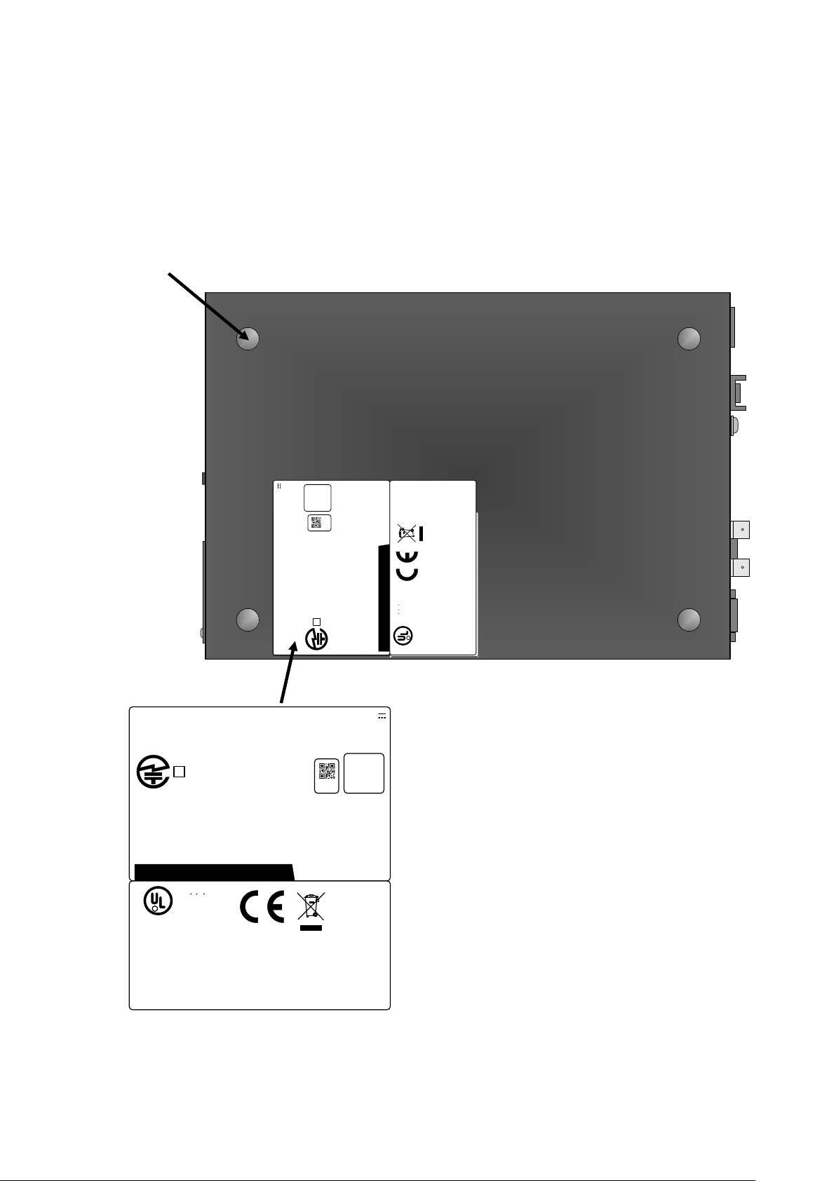
LABEL
Label:IP-9
20E/DC
LISTED
R
C
US
1K
91
I T E
E136004
Manufacture
Fujitsu Limited
Address: 1-1, Kamikodanaka 4
-Chome, Nakahara-
Ku, Kawasaki 211-8588, Japan
Authorised representati ve
Fujitsu Services Limited
Address: 22 Baker Street, London
, W1U
3BW, United Kingdom
CAN ICES-3 (A) / NMB
-3 (A)
MODEL
PART NO.
IP-920E/DC
TA
23742-
B7
XX
This device complies with Part 15 of the FCC Rules.
operation is subject to the following two conditions:
(1)
This device may not cause harmful interference. and
(
2) this device must accept any i nterference received
,
including i nterference that may cause undesired operation
.
MADE IN JAPAN
3.
2A
-
1.
6A
+12V
-24V
2.3
kg
FUJITSU LIMITED
T
認証番号
01
A
11
-03
00001
D08
-0454001
12345
ACCESSORY
MODEL
PART NO.
IP-920E/DC
TA23742-B72X
This device complies with Part 15 of the FCC Rules.
operation is subject to the f ollowing two conditions:
(1) This device may not cause harmful interference. and
(2) this device must accept any interference received,
including interfer ence that may cause undesired operation.
MADE IN JAPAN
3.2
A-1.6A
+12V-24V
2.3kg
FUJITSU LIMITED
T
認証番号
01A
11-03
00001
D08-0454001
00001
I T E
ACCESSORY
LISTED
R
C
US
1K91
E136004
MODEL
PART NO.
IP-920E/DC
TA23742-B72X
This device complies with Part 15 of the FCC Rules.
operation is subject to the following two conditions:
(1) This device may not cause harmful int erference. and
(2) this device must accept any inter ference received,
including inter ference that may cause undesired operation.
MADE IN JAPAN
3
.2A
-1.6
A
+12V-
24V
2.3kg
FUJITSU LIMITED
T
認証番号
01A
11
-03
00001
D08
-0454001
12345
LISTED
R
C US
1K91
I T E
E136004
Manufacture
Fujitsu Limited
Address: 1-1, Kamikodanaka 4-Chome, Nakahara-Ku, Kawasaki 211-8588, Japan
Authorised representative
Fujitsu Services Limited
Address: 22 Baker Street, London, W1U 3BW, United Kingdom
CAN ICES-3 (A) / NMB-3 (A)
MODEL
PART NO.
IP-920E/DC
TA23742-B7XX
This device complies with Part 15 of the FCC Rules.
operation is subject t o the following two conditions:
(1) This device may not cause harmful int erference. and
(2) this device must accept any inter ference received,
including inter ference that may cause undesired operation.
MADE IN JAPAN
3.2A-1.6A
+12V-24V
2.3kg
FUJITSU LIMITED
T
認証番号
01A
11-03
00001
D08-0454001
12345
ACCESSORY
The warning label shown below is affixed to
・ Never remove the label.
・ Be sure to check the label at the bottom of this device before coming to the power supply.
・ The following label is intended for users of this equipments.
Mark for rubber feet
this equipment.
IP-920E/DC
ix
Page 12

PRODUCT HANDLING PRECAUTIONS
WARNING
CAUTION
Maintenance
Do not try to repair this equipment yourself. Contact a Fujitsu Service
Center.
Read this manual thoroughly before attempting to operate this equipment.
If you have any questions, contact a Fujitsu Service Center.
If a problem occurs, contact a Fujitsu Service Center.
The Fujitsu Service Center will ask you to describe the problem, the lamp display status of
alarm LEDs and other details. Check the system for this information.
Connectable devices
Only devices that conform to this equipment interface specifications (see Appendix 2.3, "Device
Specifications") can be connected. Otherwise, if incompatible devices are connected, the result
may be personal injury and property damage.
CF card consideration
Please note that you need to remove the CF card or take the backup of its recorded data in case of
requesting the repair of the main unit that the CF card is installed, since Fujitsu does not guarantee
the recorded content during the repair work.
Please also note that the recorded content might be deleted by the process of the diagnostic and
the repair work after Fujitsu starts the work even if you already cancel the repair request
Disposal
To dispose of this equipment, contact a Fujitsu Service Center, or request a specialist to take care
its disposal.
Modification and restoration
Do not use any device that has been modified or rebuilt with refurbished used parts. Doing so
may result in personal injury and property damage.
IP-920E/DC
x
Page 13

CONTENTS
Chapter 1 Preparations .......................................................................... 1
1.1 Main Features ......................................................................................... 3
1.2 Components ........................................................................................... 4
1.3 Basic Application Examples ................................................................... 5
1.4 Part Names ............................................................................................. 6
Chapter 2 Installation and Connection ................................................. 9
2.1 Installation Conditions .......................................................................... 11
2.1.1 Environment conditions ........................................................... 11
2.1.2 Installation environment ........................................................... 11
2.1.3 Air supply and exhaust of the equipment ................................ 30
2.1.4 Open space required around this equipment .......................... 31
2.2 Power Supply System Connections ........................................................ 32
2.2.1 Connection to ground .............................................................. 32
2.2.2 Connection to power source .................................................... 33
2.3 Audio and Video Device Connections .......................................................... 35
2.4 Connection to Network ......................................................................... 36
2.5 Connection to RS-232C Device ........................................................... 37
2.6 CF Card Insertion and Removal ........................................................... 38
Chapter 3 Operation Instructions........................................................ 41
3.1 Turn ON/OFF IP-920E/DC ................................................................... 43
3.1.1 Turn on IP-920E/DC .................................................................. 43
3.1.2 Turn off IP-920E/DC .................................................................. 43
3.2 Device Settings and Operation ............................................................ 44
3.2.1 Reboot ....................................................................................... 45
3.3 Special Use of MNT Button .................................................................. 46
Chapter 4 Cable Specifications ........................................................... 47
4.1 Installation Preparations ....................................................................... 49
4.2 Cable and Connector Details ............................................................... 50
Chapter 5 Troubleshooting .................................................................. 59
5.1 Help Information ................................................................................... 61
5.2 Alarm LED Lamp Is On ........................................................................ 65
5.3 Maintenance ......................................................................................... 67
5.3.1 Maintenance space ................................................................... 67
5.3.2 Change equipment (Only for CE) .............................................. 68
IP-920E/DC
I
Page 14

Appendix ................................................................................................. 69
A.1 Appearance .......................................................................................... 71
A.2 Basic Specifications .............................................................................. 73
A.2.1 External specifications ............................................................... 73
A.2.2 Environment specifications........................................................ 73
A.2.3 Function specifications .............................................................. 74
A.3 Preparations for Installation Work ........................................................ 79
A.3.1 Scope of installation work .......................................................... 79
A.3.2 Unpacking and device check..................................................... 79
A.3.3 Installation conditions ................................................................ 79
A.3.4 Connecting external cables ....................................................... 79
A.4 Preparations for On-site Turn-up .......................................................... 80
Glossary and Index ................................................................................ 83
Glossary ......................................................................................................... 85
Index .............................................................................................................. 88
CE Conformity Information ............................................................................ 90
IP-920E/DC
II
Page 15

CHAPTER 1
Chapter 1 Preparations
This chapter describes the checks that are required before the start of IP-920E/DC
operation.
PREPARATIONS
1.1 Main Features .............................................................................................. 3
1.2 Components ................................................................................................. 4
1.3 Basic Application Examples ......................................................................... 5
1.4 Part Names .................................................................................................. 6
Page 16

(This page is intentionally left blank)
Page 17
Chapter 1 Preparations
HD-SDI / SD-SDI
1ch
[BNC]
HDMI 1.2a (*2)
1ch
[HDMI]
Analog Composite
1ch
[BNC]NTSC/PAL
HD/SD-SDI embedded
2ch
[BNC], 1 stereo pairs
HDMI 1.2a (*2)
2ch
[HDMI]
Analog balanced
2ch
[D-sub9-pin], female connector, 1 stereo pair
[RJ45],
10BASE-T / 100BASE-TX
Data input/output
RS-232C
1ch
[D-sub9-pin], male connector
CF CARD slot
CF CARD
1
Data storage application
Installation conditions
Indoor: On a desk, mounted in a rack
Dimensions
W: 210 H: 42 D: 300 (mm) Note: Excluding protrusions (i.e., not including feet)
Cooling system
Forced air cooling
Power supply
+12-24VDC
Weight
Maximum 2.3kg
Power consumption
38.4W or less
Temperature
Humidity
-10 to 55°C (No low temperature startup: -10 to -1°C)
20 to 90%RH (No condensing)
Safety Standard
Approved as Class III device of IEC60950-1, UL60950-1, EN60950-1
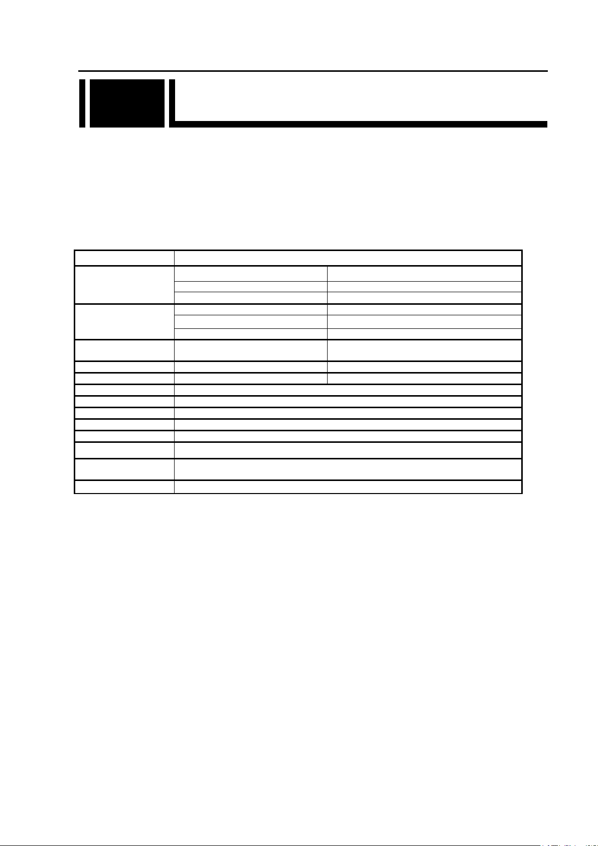
1.1 Main Features
1.1
IP-920E/DC is the video transmission unit with the H.264 encoding technology which performs the
high compression ratio, and transmits the SD (Standard Definition) /HD (High Definition) video and
audio signals in real time through even the optical IP network like FTTH.
IP-920E has functions that encodes SD/HD video signals from a SD/HD camera or similar device and
distributes it across the network in real-time.
Main Features
Item Specifications
Video input
Audio input
Network LAN 1ch
*1: IP-920E supports only SD video. By adding optional software, IP-920E will be upgraded to support HD video.
*2: DVI isn't supported.
3
IP-920E/DC
Page 18

Chapter 1 Preparations
・
・
・
CF CARD
/ACT
RDY
PWR ALM
IN
DWN
OPT
100M
LINK
E
A-IN (L)
A
I
N
L
(
)
A
I
N
R
(
)
1.2 Components
1.2
The IP-920E/DC product package consists of the following components.
Attachments for all series consist of same contents.
・
IP-920E/DC: 1 pc (cables separate order)
Safety manual: 1pc ・ User’s Guide: 1pc
Feet: 4 pcs ・DC Power cable: 1 pc
Audio adapter cable (type 1) : 1 pc
IP-920E/IP-920D
4
Page 19
Chapter 1 Preparations
CF CARD
/ACT
RDY
PWRALM
IN
DWN
OPT
100M
LINK
E
IP-920E
/DC
CF CARD
/
ACT
RDY
PWR
ALM
IN
DWN
OPT
100M
LINK
E
IP
-920E/DC
CF CARD
/ACT
RDY
PWR
ALM
IN
DWN
OPT
100M
LINK
E
RDY
PWRALM
DEC
MNT
FG
/ACT
100M
LINK
10/100BASE RS-232C
ANALOG
VIDEO OUT
100-240V
SDI
D
ANALOG AUDIO OUT
IP Network
FTTB
/ FTTH
Dart Fiber
AP
AP
HD
VTR
HD Camera
AP
Encoder Site
Live Coverage
IP
-920
E
/DC
Monitoring
Control
HD Archive Server
Strage(NR)
AP
Dual Encoding (
SD
)
File Transfer by Flow Control
HD VTR
Video Editing
Equipment
On demand file transfer
From affiliates
Decoder Site
1
U サーバー
Live Coverage
IP-920
D
HD Camera
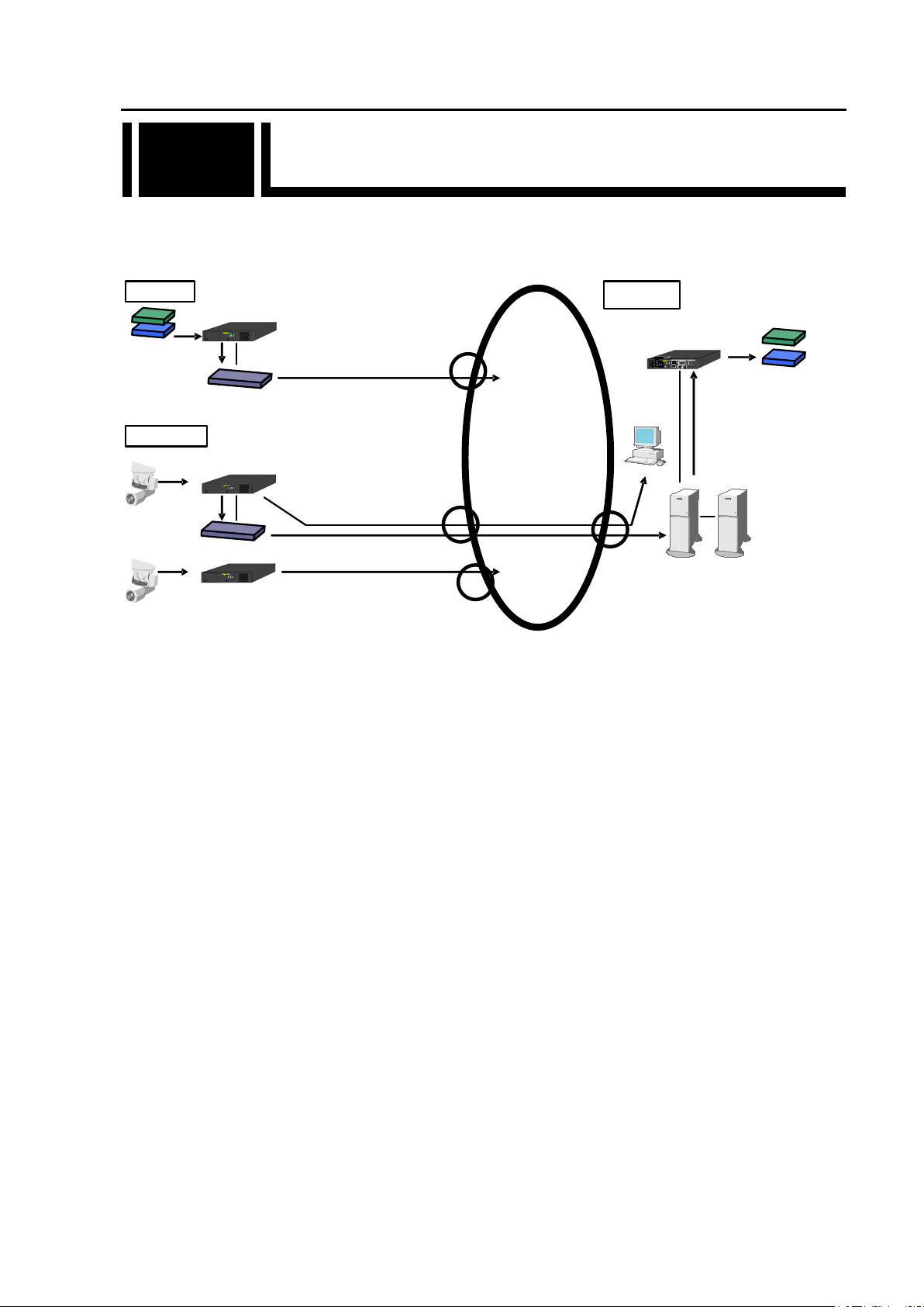
1.3 Basic Application Examples
1.3
Examples (sys tem configuration) of use of IP-920E/DC are shown below.
5
IP-920E/DC
Page 20
Chapter 1 Preparations
By using a DC power cable attached to IP-920E/DC, it enables to connect to a
connection information.
(2)
Power button
Turns this equipment on and off.
(3)
Power LED (PWR)
Turns on when this equipment is powered on.
Status LED
(RDY)
Turn on when IP-920E power is on. For more information, see Table 5.3,
“Details of LED Indications,” in Section 5.2.
Alarm LED
(ALM)
Turns on when IP-920E operation is abnormal. For more information, see
Table 5.3, “Details of LED Indications,” in Section 5.2.
Audio/Video input setting status indicator and LED that indicates the input off
LED Indications,” in Section 5.2.
Option LED
(OPT)
Turn on when option license is installed. For more information, see Software
guide.
RDY
PWR ALM
IN
DWN
OPT
MNT
FG
/
ACT
100M
LINK
10
/
100BASE
RS
-
232C
ANALOG
VIDEO IN
SDI
ANALOG AUDIO IN
12
-
24
V
E
(
2)
(
7
)
(
8)
(
9)
(10
) (
11
)
(12
)
(13
)
(
14)
(15
)
(
16)
(
17
)
(1
)
(
3)
(
4
)
(
5
)
(
6
)
E
/
ACT
RDY
PWR
ALM
IN
DWN
OPT
100M
LINK
11
CF CARD
AUX
(18
)
(19
)
(20
)
(3) (4) (5) (6) (7)
(9
)
(10)
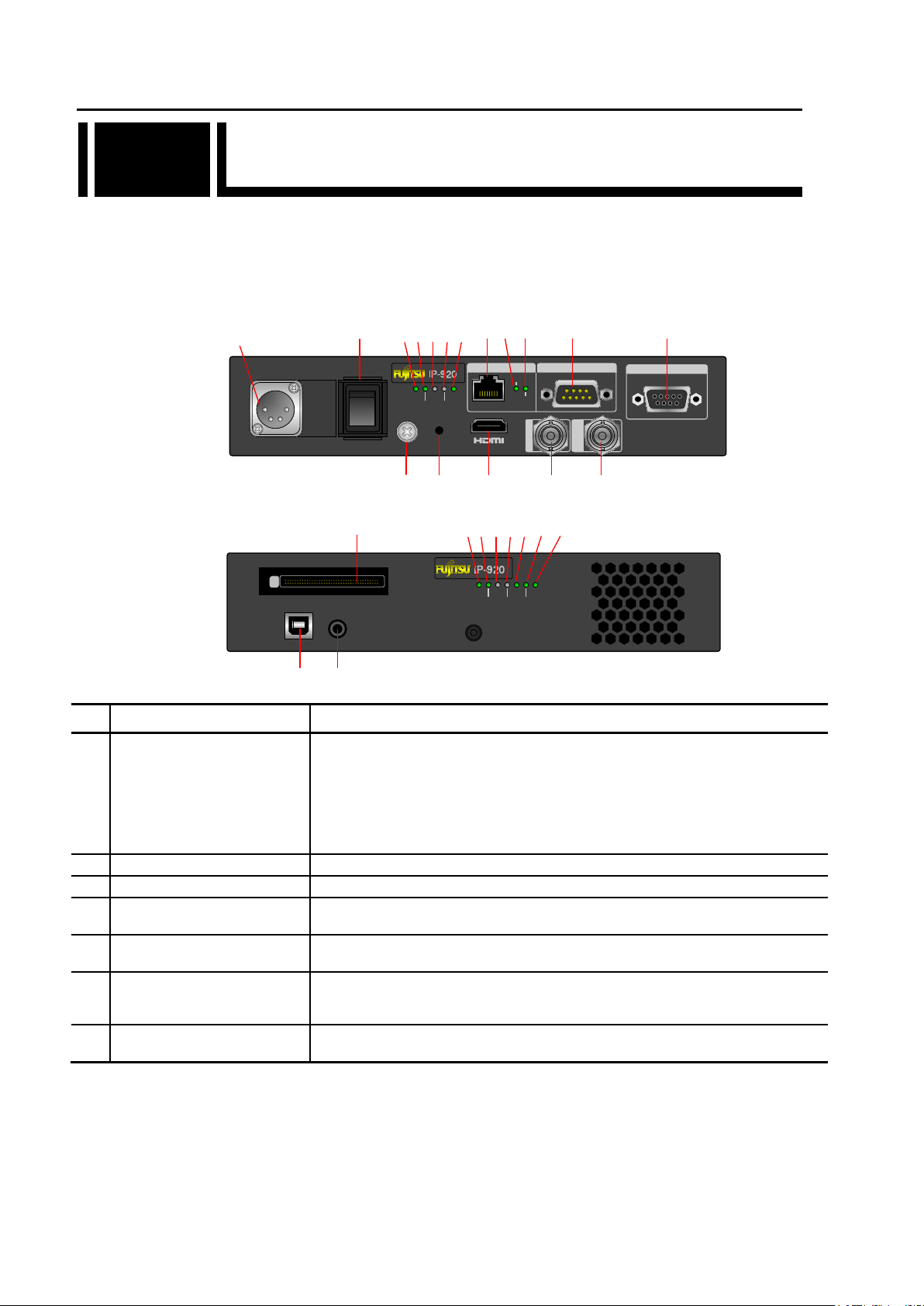
1.4 Part Names
1.4
This section gives the name and describes the function of individual parts of IP-920E/DC.
The diagrams below show the layout of parts on the outside of this equipment, and the table below
lists the name and describes t he function of individual parts.
- IP-920E/DC
Figure Front panel
Figure Rear panel
Part names
No. Name Description
power supply of DC12-24V.
Power inlet connector
(1)
(DC +12-24V)
However, a connectable power-source equipment needs to be SELV (*) safety
status.
See Section 2.2.2, “Connection to a Power Source,” for an explanation on using
this connector. See Section 4.2, “Cable and Connector Details,” for cable
(4)
(5)
AV input status LED
(6)
(INDWN)
status during input setting. For more information, see Table 5.3, “Details of
(7)
* SELV is a secondary circuit protected in the structure that electrical potential difference between any two
touchable points is not dangerous under the normal condition or even under the condition that any one point is
broken. It indicates up to 60V in case of DC voltage.
IP-920E/IP-920D
6
Page 21

Names
Description
Ethernet 10BASE-T/100BASE-TX communication port. See Section 2.4,
4.2, “Cable and Connector Details,” for cable connection information.
Speed LED
(100M)
Indicates the status of LAN port. For more information, see Table 5.3, “Details
of LED Indications,” in Section 5.2.
Status LED
(LINK/ACT)
Indicates the speed of LAN port. For more information, see Table 5.3, “Details
of LED Indications,” in Section 5.2.
RS-232C data communication port.
connection information.
Audio input terminal. 600Ω balanced.
connection information.
Use for an FG connection to this equipment.
terminal.
IP-920E start mode selector switch. when the IP-920E is powered on with this
switch.
Digital HDMI video input terminal. 50Ω unbalanced.
connection information.
Digital HD-SDI video input terminal. 75Ω unbalanced.
connection information.
Analog video input terminal. 75Ω unbalanced.
connection information.
AUX port
(AUX)
(20)
Test port
Factory test port.
No.
Chapter 1 Preparations
LAN port
(8)
(10/100BASE)
(9)
(10)
RS-232C port
(11)
(RS-232C)
Audio input
(12)
(ANALOG AUDIO IN)
FG terminal
(13)
(14)
(15)
)
(FG
Maintenance mode switch
(MNT)
HDMI input
(HDMI)
“Connection to a Network,” for an explanation on using this port. See Section
See Section 2.5, “Connection to an RS-232C Device,” for an explanation on
using this pin. See Section 4.2, “Cable and Connector Details,” for cable
See Section 2.3, “Audio and Video Device Connections,” for an explanation on
using this terminal. See Section 4.2, “Cable and Connector Details,” for cable
See Section 2.2.1, “Connection to ground,” for an explanation on using this
switch held down, it starts in initial start mode.
See section 3.3, “Special Use of MNT Button,” for an explanation on using this
See Section 2.3, “Audio and Video Device Connections,” for an explanation on
using this terminal. See Section 4.2, “Cable and Connector Details,” for cable
SDI video input
(16)
(SDI)
Video input
(17)
(ANALOG VIDEO IN)
CF CARD slot
(18)
(19)
See Section 2.3, “Audio and Video Device Connections,” for an explanation on
using this terminal. See Section 4.2, “Cable and Connector Details,” for cable
See section 2.3, “Audio and Video Device Connections,” for an explanation on
using this terminal. See Section 4.2, “Cable and Connector Details,” for cable
Slot in which a CompactFlash@ card is inserted.
Auxiliary port.
7
IP-920E/DC
Page 22

(This page is intentionally left blank)
Page 23

CHAPTER 2
Chapter 2 Installation and Connection
INSTALLATION AND
CONNECTION
This chapter describes conditions for IP-920E/DC installation and explains how to
connect it to peripheral devices.
2.1 Installation Conditions ................................................................................ 11
2.2 Power Supply System Connections .............................................................. 32
2.3 Audio and Video Device Connections ................................................................ 35
2.4 Connection to Network ............................................................................... 36
2.5 Connection to RS-232C Device ................................................................. 37
2.6 CF Card Insertion and Removal ................................................................ 38
Page 24

Possibility of serious injury
The power cord and other cables connected to IP-920E/DC may become
entangled with someone walking close to them, possibly leading to serious
injury and property damage. Clamp the cables to the rack or floor.
Page 25

Chapter 2 Installation and Connection
2.1 Installation Conditions
2.1
This section describes the installation environment, space and air supply and exhaust of the
equipment.
2.1.1 Environment conditions
Please use this equipment in the air supply and ambient temperature which is not exceeded 55
degrees C. If the condition above is observed, you may install plural equipment as piling on a shelf.
In case of using this equipment under unsupported conditions, the equipment cannot be supported
by Fujitsu and it might be the cause of failure and shortening the product life remarkably.
Use this Equipment in the environment which airborne dust is under 0.15mg/m3. (In case of being
over 0.15mg/m3, use dust-proofing rack.) In addition, clean up around this equipment because
remarkably amount of dust is the cause of equipment errors and failures if it is attached to the
equipment.
Use this Equipment in the environment which gaseous contamination is under “IEC 60721-3-3
Class 3C1”.(Refer to “Appendix 2.2 Environment Specifications - Gaseous contamination”).
2.1.2 Installation environment
1. 19” rack mounting
Mount this equipment to 19” rack of EIA standard using the 19” rack mounting kit. We have 2
types of mounting kits; 1 unit per 1 U and 2 units per 1U.
(19” rack mounting kit is an optional product.)
If you would like to mount different way from the descriptions in this document, please
consult Fujitsu Service Center or your system administrator.
5 types of rack mounting kit are available. (Type A1, A2, B1, B2 and C2)
Use attached mounting kit and screws for installing equipment. Fix the
equipment tightly with the attached rack using attached screws. In case of
loosening the screws or not being fixed tightly with the equipment, it may be
a cause of serious accident.
11
IP-920E/DC
Page 26
Chapter 2 Installation and Connection
C
B A D
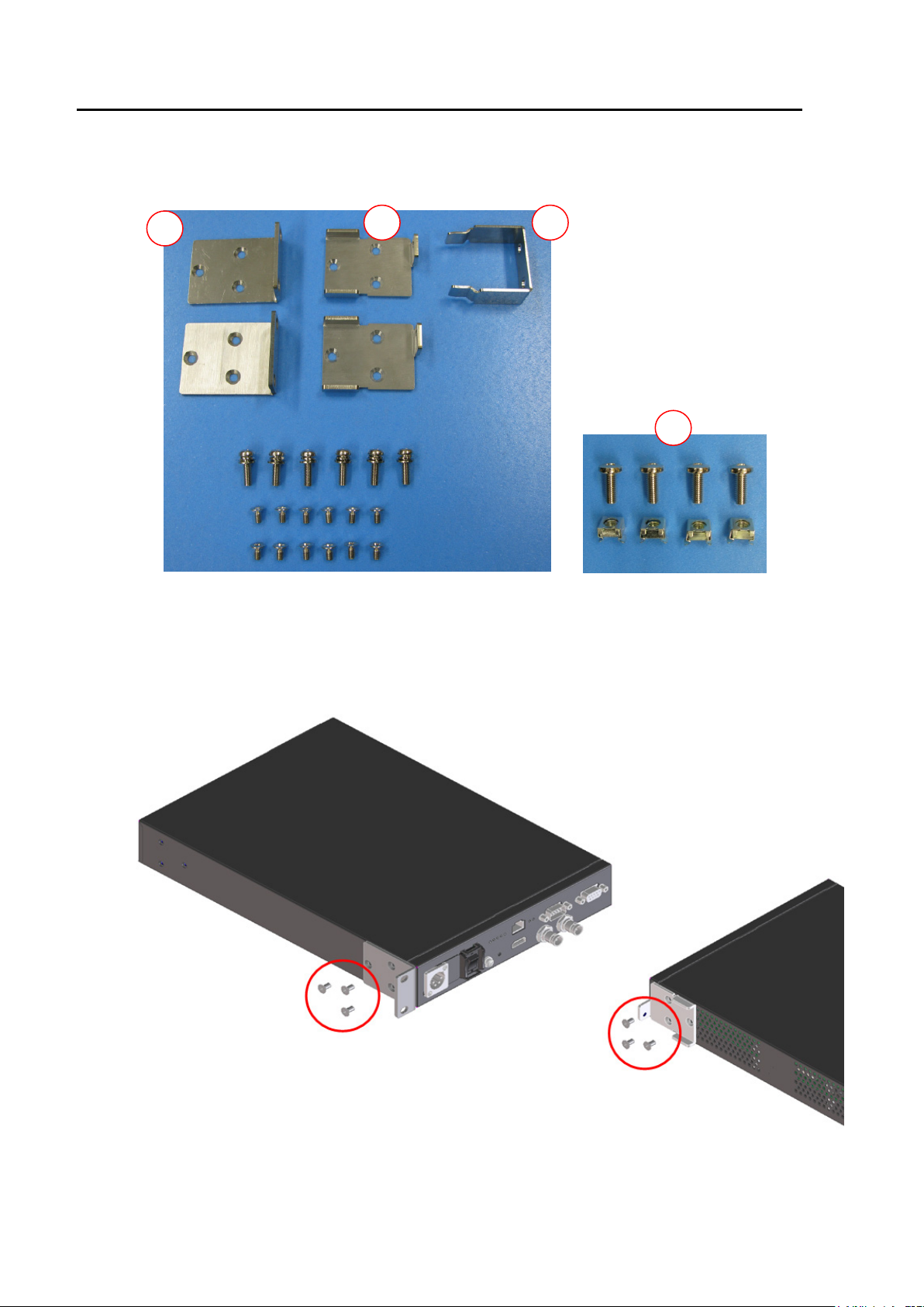
- Two IP-920 per 1U (Type C2)
(1) Check contents of the rack mounting kit.
(2) Check all cables disconnected.
(3) Connect the first device with the rack mounting kit “A” and “B” on IP-920 using six same
screws (M4).
IP-920E/DC
12
Page 27
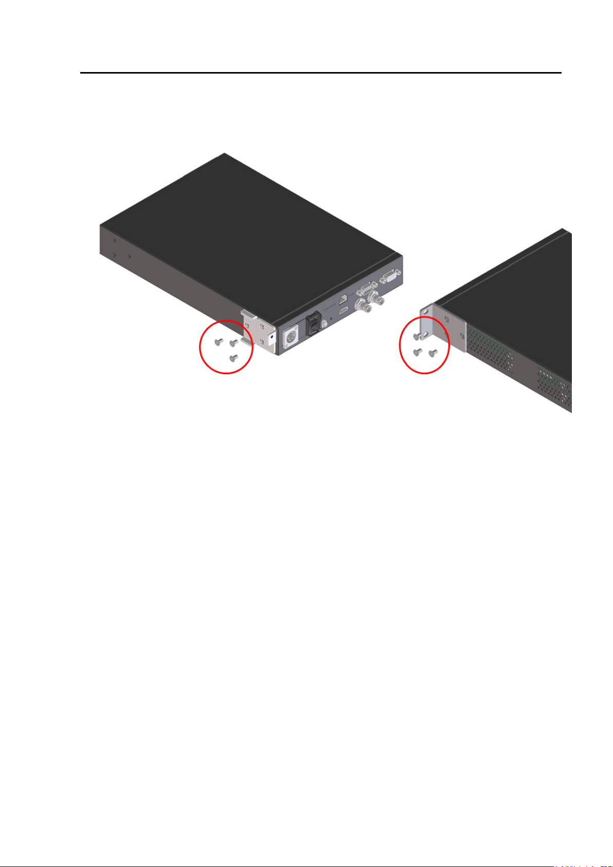
Chapter 2 Installation and Connection
(4) Connect the second device with the rack mounting kit “A” and “B” on IP-920 using six same
screws (M4).
13
IP-920E/DC
Page 28
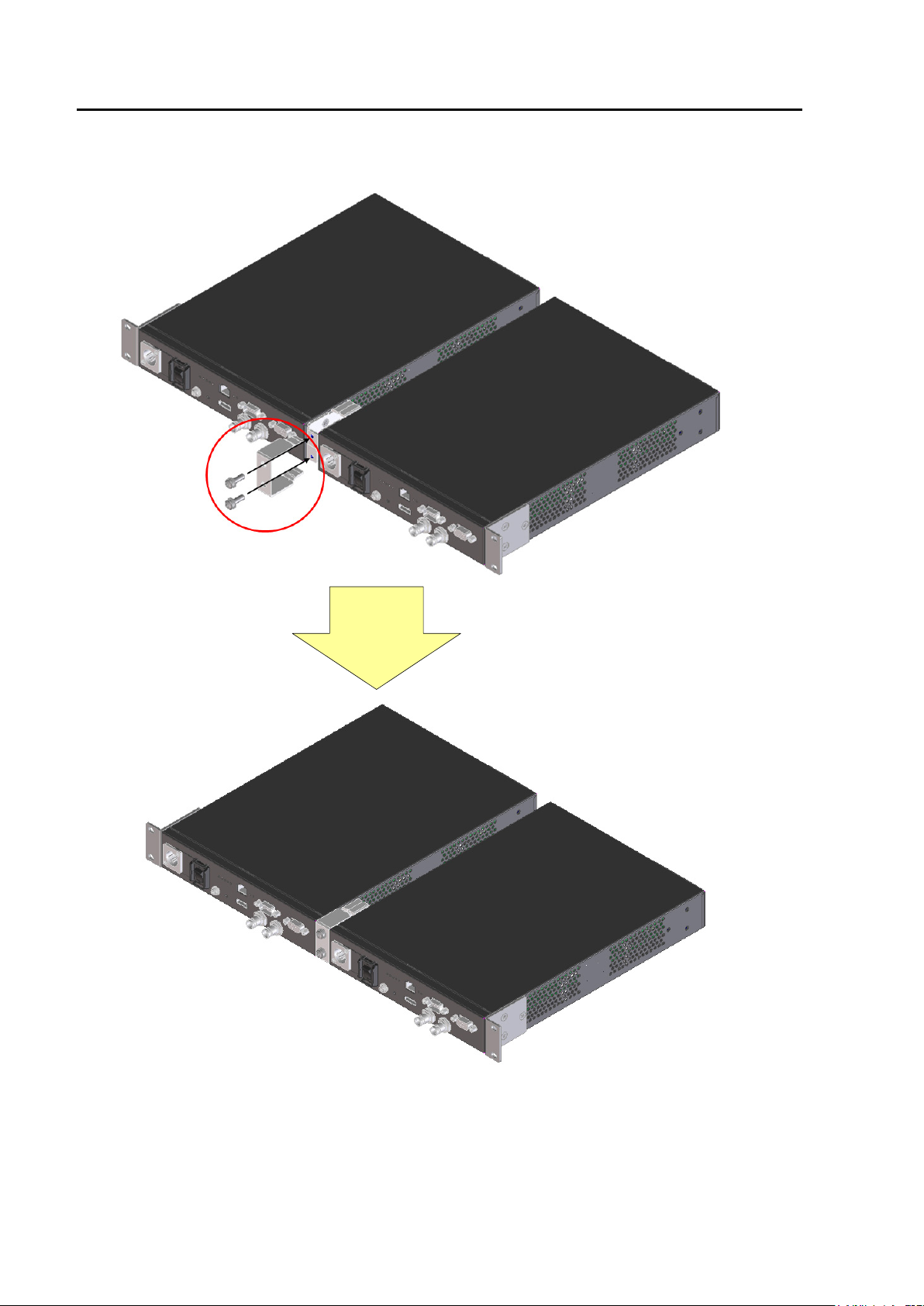
Chapter 2 Installation and Connection
(5) Install the mounting kit C on IP-920 using two pan head screws (M5).
IP-920E/DC
14
Page 29
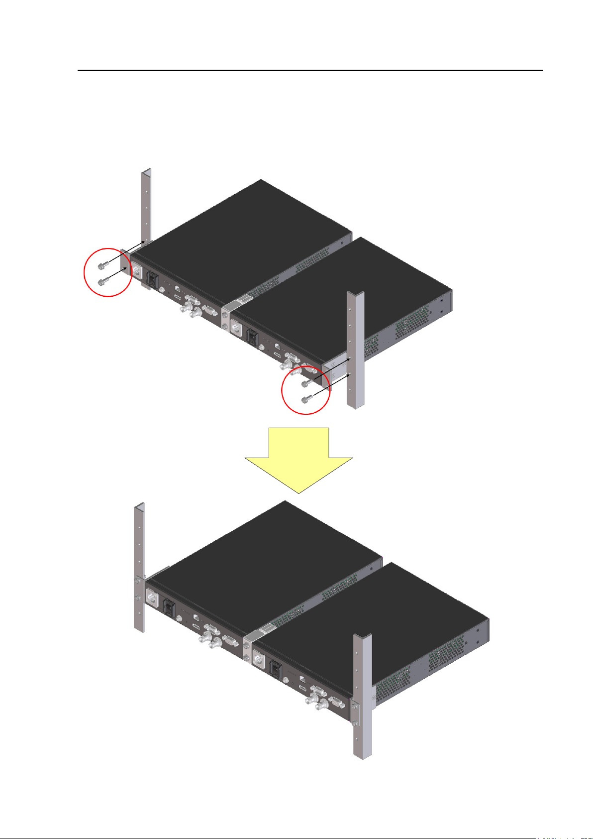
Chapter 2 Installation and Connection
(6) Align the main unit at the desired height on the 19" rack, and firmly secure the unit in position
with the screws supplied with this product. Use four pan head screws (M5) to fix the product in
position.
To secure the unit to a server rack, use the cage nuts (D) and bind head screws (M6) supplied with
this product.
15
IP-920E/DC
Page 30

Chapter 2 Installation and Connection
- Removing the device
(1) When removing two devices at the same time
Remove them by reversing the installation procedure for two devices.
(2) When removing only one device
Remove the four screws shown in the figure below.
Remove the mounting brackets (C), and then remove the device.
IP-920E/DC
16
Page 31

Chapter 2 Installation and Connection
B
A
- 1 unit per 1U (Type A1)
(1) Check components of the rack mounting kit.
(2) Check all cables are disconnected.
(3) Install the rack mounting kit “A” on IP-920 using three same screws (M4).
IP-920E/DC
17
Page 32

Chapter 2 Installation and Connection
(4) Install the rack mounting kit “B” on IP-920 series using three same screws (M4).
(5) Install IP-920 on 19” rack using four pan head screws (M5).
- Removing the device
Remove the device by reversing the installation procedure.
IP-920E/DC
18
Page 33

Chapter 2 Installation and Connection
C B A
- 2 units per 1U (Type A2)
(1) Check components of the rack mounting kit.
(2) Check all cables are disconnected.
(3) Connect the first device with the rack mounting kit “A” and “B” on IP-920 using six same
screws (M4).
IP-920E/DC
19
Page 34

Chapter 2 Installation and Connection
(4) Install IP-920 on 19” rack using two pan head screws (M5).
(5) Connect the second device with the rack mounting kit “A” and “B” on IP-920 using six same
screws (M4).
IP-920E/DC
20
Page 35

Chapter 2 Installation and Connection
(6) Install IP-920 on 19” rack using two pan head screws (M5).
21
IP-920E/DC
Page 36

Chapter 2 Installation and Connection
(7) Install the mounting kit C on IP-920 using two pan head screws (M5).
- Removing the device
Remove the device by reversing the installation procedure.
IP-920E/DC
22
Page 37

Chapter 2 Installation and Connection
B
A
C
- 1 unit per 1U(Type B1)
(1) Check components of the rack mounting kit.
(2) Check all cables disconnected.
(3) Install the rack mounting kit A on IP-920 using three same screws (M4).
IP-920E/DC
23
Page 38

Chapter 2 Installation and Connection
(4) Install the rack mounting kit B on IP-920 using three same screws (M4).
(5) Install the rack mounting kit C on IP-920 and rack mounting kit B using four screws (M4).
IP-920E/DC
24
Page 39

Chapter 2 Installation and Connection
(6) Install IP-920 on 19” rack using four pan head screws (M5).
- Removing the device
Remove the device by reversing the installation procedure.
25
IP-920E/DC
Page 40

Chapter 2 Installation and Connection
Coupling fittings
Mounting fittings
- - 2 units per 1U(Type B2)
(1) Check contents of the rack mounting kit.
(2) Check all cables disconnected.
(3) Connect the first device with the connecting kit using six same screws (M4).
(4) Connect the second device with the connecting kit using six same screws (M4).
IP-920E/DC
26
Page 41

Chapter 2 Installation and Connection
(5) Rotate the connecting kit, and fix with twelve screws (M4).
(Bottom view)
(Top view)
27
IP-920E/DC
Page 42

Chapter 2 Installation and Connection
(6) Install the mounting kit on 2 units using six same screws(M4).
(7) Install 2 units on 19” rack using four pan head screws (M5).
- Removing the device
Remove the device by reversing the installation procedure.
IP-920E/DC
28
Page 43

MODEL
PART NO.
IP-920E/DC
TA23742-B72X
This device complies with Part 15 of the FCC Rules.
operation is subject to the f ollowing two conditions:
(1) This device may not cause harmful interference. and
(2) this device must accept any interference received,
including interfer ence that may cause undesired operation.
MADE IN JAPAN
3.2A-1.6A
+12V-24V
2.3kg
FUJITSU LIMITED
T
認証番号
01A
11-03
00001
D08-0454001
00001
I T E
ACCESSORY
LISTED
R
C
US
1K91
E136004
MODEL
PART NO.
IP-920E/DC
TA23742-B72
X
This device complies with Part 15 of the FCC Rules.
operation is subject t o the following two conditions:
(1) This device may not cause harmful int erference. and
(2) this device must accept any inter ference received,
including inter ference that may cause undesired operation.
MADE IN JAPAN
3.2A-
1.6
A
+12V-24V
2.3kg
FUJITSU LIMITED
T
認証番号
01A
11-03
00001
D08-0454001
12345
Chapter 2 Installation and Connection
2. Place the equipment to a Table
Attach 4 rubber feet on the parts marked on the bottom of this equipment as below. Refer to
“Open space required around this equipment” before deciding the place for this equipment.
Mark for rubber feet
Safety installation instruction:
1) Multiple pile
The maximum 5 IP-920E/DC can be piled under the environment condition
specified. Please install considering the maintenance-ability. When
IP-920E/DC is piled, please fix them to avoid falling (do not cover the air
intake.). See Section 2.1.4, “Open space required around this equipment”
for the installation space.
2) rack mounting
a) When IP-920E/DC is installed in a closed or multi-unit rack, the
operating ambient temperature inside of the rack environment may be
greater than room ambient. Therefore, the consideration should be
given to operate in the environment compatible with the specifications
in Appendix 2.2 “Environment Specifications.”
- The consideration for adjustment of the air condition like air
circulation should be given to prevent the internal rack ambient
from exceeding the maximum operating ambient temperature of
IP-920E/DC.
- The maximum operating ambient temperature for IP-920E/DC:
55°C.
IP-920E/DC
29
Page 44

Chapter 2 Installation and Connection
–
b) The installation of IP-920E/DC in a rack should be such that the
amount of airflow required for safe operation of IP-920E/DC is not
compromised.
- IP-920E/DC has ventilation opening at the right and rear side.
- Do not cover or close these ventilation openings to prevent
overheating.
c) The mounting of IP-920E/DC in a rack should be such that a hazardous
condition in not archived due to uneven mechanical loading. To keep
stability of the entire rack, please fix the rack to wall or floor by
suitable means.
- Be careful about injury during installation of IP-920E/DC into
rack.
- Do not install IP-920E/DC into your rack where IP-920E/DC may
make the entire rack unstable.
- The weight of IP-920E/DC with the maximum configuration: 2.3
kg
d) When using a bracket for mounting two products and you remove one
product, do not leave the remaining one that is fixed at one end only
unattended. If you apply pressure to a product that is supported at
one end only, it may deform the mounting bracket.
e) Confirm that power supplying capacity of power tap is larger than the
total nominal power of all devices connected in the rack.
The nominal power of IP-920E/DC is DC +12-24V, 3.2
1.6 A.
2.1.3 Air supply and exhaust of the equipment
IP-920E/DC is forced air cooled equipment. Be sure not to block the air intake/exhaust vents.
Provide an adequate amount of space around the vents.
IP-920E/DC
30
Page 45

Chapter 2 Installation and Connection
2.1.4 Open space required around this equipment
Provide the indicated (parts with hatched area) below, cable forming space, operation space and
air intake/exhaust.
For the information of maintenance space, see Section 5.3.1, “Maintenance space.”
31
IP-920E/DC
Page 46

Chapter 2 Installation and Connection
RDY
PWR ALM
IN
DWN
OPT
MNT
FG
/ACT
100M
LINK
10/100BASE
RS-232C
ANALOG
VIDEO IN
SDI
ANALOG AUDIO IN
12 - 24V
E
2.2 Power Supply System Connections
2.2
This section explains ground and power-source connections.
2.2.1 Connection to ground
When the exogenous noise influences IP-920E/DC, connect the FG terminal to an external ground.
FG terminal (M4)
Figure Connection to ground
IP-920E/DC
32
Page 47

2.2.2 Connection to power source
RDY
PWR ALM
IN
DWN
OPT
MNT
FG
/ACT
100M
LINK
10/100BASE RS-232C
ANALOG
VIDEO IN
SDI
ANALOG AUDIO IN
12 -
24V
E
Power connector
To connect a cable, insert it until
it clicks into place.
To remove a cable, unplug it
while holding down the button.
DC power output equipment
(SELV safety status)
PUSH
IP-920E/DC is safety-approved Class III devices of IEC60950-1, UL60950-1 and EN60950-1.
Therefore, IP-920E/DC needs power source from SELV. Also, in case of using this device in the
United States, it needs to be a UL60950-1 approved power-supply unit.
Prepare a power-supply unit outputting DC12-24V with a power consumption of more than 40W
and connect to this equipment by using the attached DC power cable.
* In case of using non-attached power cable, select a power cable referring to (9) in “4.2 Cable
Connector Details.”
Also, power cable can be ordered separately with your suitable length.
<Reference>
・DC power cable (3m) : TA77057-3000 (normally attached)
・DC power cable (length specification) : TA77057-xxxx (Maximum length : 3m)
(TA77057-0500 is 0.5m, TA7 7057-2000 is 2m)
Chapter 2 Installation and Connection
Figure Power cord connection
IP-920E/DC
33
Page 48

Chapter 2 Installation and Connection
Possibility of electric shock, fire, and damage to this equipment
Always observe the precautions given below.
This indicates a hazardous situation that could lead to electric shock, fire, or
damage to this equipment.
Use a DC power cable attached to IP-920E/DC. If the attached power cable
is unusable, select a power cable referring to (9) in “4.2 Cable and Connector
Details.”
Use a power-supply unit outputting DC12-24V with a power consumption of
more than 40W.
IP-920E/DC
34
Page 49

Chapter 2 Installation and Connection
RDY
PWR ALM
IN
DWN
OPT
MNT
FG
/ACT
100M
LINK
10
/100BASE RS
-232C
ANALOG
VIDEO IN
SDI
ANALOG AUDIO IN
12 - 24V
E
Audio adapter cable#1
or
Audio adapter cable
#3
PUSH
or
PUSH
A
-
I
N
R
(
)
A-IN (L)
A
-
I
N
L
(
)
or
Video & Audio Output Device
NOT E:
2.3 Audio and Video Device Connections
2.3
2 Digital and 1analog video input connectors are equipped for connecting with video output equipment.
- SDI Video Input (Digital Video)
Connect to SDI IN connector using BNC cable. Input digital HD-SDI or SD-SDI signal.
The signal is terminated with 75Ω impedance.
- HDMI Input (Digital Video)
Connect to HDMI connector on front panel of IP-920E/DC using the HDMI cable.
Input digital signal of HDMI. The signal is terminated with 50Ω.
- Analog Video Input
Connect to ANALOG VIDEO IN connector using
BNC cable with NTSC or PAL signal.
2 Digital and 1analog audio input connectors are equipped for connecting with audio output equipment.
- Digital Audio Input
SDI Embedded Audio and HDMI audio are supported.
- Analog Audio Input
Connect to ANALOG AUDIO IN connector of IP-920E using the audio adaptor cable.
The figure of cable connections are shown below.
For details about connectors and cables, see Section 4.2, “Cable and Connector Details.”
For electrical specifications, see Appendix 2.3, “Function Specifications.”
Figure Audio and video output device connections
35
IP-920E/DC
Page 50

Chapter 2 Installation and Connection
RDY
PWR ALM
IN
DWN
OPT
MNT
FG
/ACT
100M
LINK
10/100BASE RS-232C
ANALOG
VIDEO IN
SDI
ANALOG AUDIO IN
12 - 24V
E
Hub, Router, PC, etc.
CAUTION
NOT E:
2.4 Connection to Network
2.4
To connect IP-920E/DC to a LAN device, connect the LAN device to the LAN communication port
of IP-920E/DC using a LAN cable (UTP cable). The LAN communication port specification of
IP-920E/DC is 10BASE-T/100BASE-TX.
The figure below shows the connection method.
For details
about connectors and cables, see Section 4.2, “Cable and Connector Details.”
For electrical specifications, see Appendix 2.3, “Function Specifications.”
Figure Connection to a network
IP-920E/DC
Please do not provision the IP address below.
・ IP address commonly unused(0.0.0.0,255.255.255.255,etc…)
・ Loop back address (127.xxx.xxx.xxx)
・ Class D and Class E addresses
・ IP address already used
For more information, see IP-920E/DC Software User’s Guide.
36
Page 51

Chapter 2 Installation and Connection
RDY
PWR ALM
IN
DWN
OPT
MNT
FG
/
ACT
100M
LINK
10
/
100BASE
RS-232C
ANALOG
VIDEO IN
SDI
ANALOG AUDIO IN
12
-
24
V
E
Data communication
device
D
-sub
9pin(female
)
NOT E:
2.5 Connection to RS-232C Device
2.5
The [RS-232C] connector of IP-920E/DC is the RS-232C communication terminal. The terminal of
IP-920E/DC is the D-sub 9 pins (male) and the specification is DTE. Use a cross connection or straight
cable corresponding to the connected device. See Section 4.2, “Cable and Connector Details.”
The figure below shows the connection method.
For details about connectors and cables, see Section 4.2, “Cable and Connector Details.”
For electrical specifications, see Appendix 2.3, “Function Specifications.”
Figure Connection to RS-232C input/output device
IP-920E/DC
37
Page 52

Chapter 2 Installation and Connection
(1) Check if the power is OFF.
(2) Screw out.
Eject button
CF card
(4) Press the eject button and remove the CF card.
※CF card is unequipped initially (Separate order).
(5) Replace CF card and cover it.
(3) Remove the cover.
2.6 CF Card Insertion and Removal
2.6
In order to insert the CF card, the front cover of IP-920E/DC must be opened by screwing out the cover.
No storage card is supplied with IP-920E/DC. It can be procured separately, depending on the system.
The CF card removal procedure is shown below.
Please turn off the power to insert or remove the CF card.
Please contact Fujitsu office what type of CF card is available to use.
IP-920E/DC
38
Page 53

Chapter 2 Installation and Connection
Updating the Software
The CF card is formatted when upgrading from before V02L002 to after V02L010. Please back up
necessary data of the CF card before it upgrades.
CF card consideration
Please note that you need to remove the CF card or take the backup of its recorded data in case of
requesting the repair of the main unit that the CF card is installed, since Fujitsu does not guarantee
the recorded content during the repair work.
Please also note that the recorded content might be deleted by the process of the diagnostic and
the repair work after Fujitsu starts the work even if you already cancel the repair request
39
IP-920E/DC
Page 54

Page 55

Chapter 3 Operation Instructions
OPERATION INSTRUCTIONS
This section explains how to power on/off, setup and operate this equipment.
CHAPTER 3
3.1 Turn ON/OFF IP-920E/DC ......................................................................... 43
3.2 Device Settings and Operation .................................................................. 44
3.3 Special Use of MNT Button ........................................................................ 46
Page 56

(This page is intentionally left blank)
Page 57

Chapter 3 Operation Instructions
RDY
PWR ALM
IN
DWN
OPT
MNT
FG
/ACT
100M
LINK
10/100BASE
RS-232C
ANALOG
VIDEO IN
SDI
ANALOG AUDIO IN
12 - 24V
E
RDY
PWR ALM
IN
DWN
OPT
MNT
FG
/ACT
100M
LINK
10/100BASE
RS-232C
ANALOG
VIDEO IN
SDI
ANALOG AUDIO IN
12 - 24V
E
Power button
Power(PWR) LED
Status(RDY) LED
3.1 Turn ON/OFF IP-920E/DC
3.1
This section explains how to power on/off the IP-920E/DC.
3.1.1 Turn on IP-920E/DC
When the power button on the front panel is set to the [ | ] position, the PWR LED turns on.
When IP-920E/DC completes preparations for operation, the RDY LED turns on.
This indicates the on switch, which is used to supply power to the IP-920E/DC.
|
This indicates the off switch, which is used to disconnect power from the IP-920E/DC.
○
3.1.2 Turn off IP-920E/DC
When the power button on the front panel is set to the [O] position, this equipment is turned off
and the PWR LED turns off.
IP-920E/DC
43
Page 58

Chapter 3 Operation Instructions
Connect IP-920E/DC and PC
using UTP cable
- Check if IP-920E/DC is disconnected to user’s network.
- Connect using UTP cable.
- When connect through LAN port, the default IP address and subnet
mask are 10.0.0.1 and 255.0.0.0 respectively. Assign 10.xxx.xxx.xxx for
PC.
(ex. IP address: 10.0.0.2, Subnet mask: 255.0.0.0)
for PC.
For details, please refer to the Software User's Guide.
Turn ON IP-920E/DC
- Execute the Network setting from WEB GUI after the device starts.
For details, please refer to the Software User's Guide.
Change network settings
(Refer the software user’s guide)
Connect user’s network
Start settings and operations
(Refer the software user’s guide)
3.2 Device Settings and Operation
3.2
■Setup Procedure
The setup procedure is shown below.
See Software User’s Guide for the procedure of the software installation and the each setting.
■Web browser recommended
The recommended web browser is as follow.
- Internet Explorer 6.0 SP2 or later
IP-920E/DC
44
Page 59

This section briefly explains the basic functions of the setup pages.
3.2.1 Reboot
Clicking the button displayed in the left frame of the browser reboots this equipment.
When you click the button, the following dialog box shown below appears for confirmation. Click
OK to reboot.
Chapter 3 Operation Instructions
45
IP-920E/DC
Page 60

Chapter 3 Operation Instructions
3.3 Special Use of MNT Button
3.3
You can start IP-920E/DC by turning on the power while holding down the [MNT] Button (for
about 10 seconds) until the RDY LED begins blinking in orange. Doing so starts the IP-920E/DC
with the initial IP address and subnet mask with which the IP-920E/DC is shipped from the factory
(IP address 10.0.0.1, Subnet mask: 255.0.0.0).
Use this function when making initial settings for IP-920E/DC from a control terminal (such as a
PC having a LAN interface) (*1).
*1 When you operate the IP-920E/DC with the default IP address, connect this equipment to a
control terminal and make setting from the terminal with this equipment disconnected from
your network.
After making settings according to the requirements for your network, connect this
equipment to the network. If this equipment with the default settings made at the factory is
connected to the network, an unexpected problem may occur with your network.
If you start IP-920E/DC while holding the [MNT] button, set the IP addresses and subnet
masks of the control terminal to connect as follows:
- IP address : 10.xxx.xxx.xxx
(xxx is any number from 0 to 255, excluding 10.0.0.0, 10.0.0.1, and 10.255.255.255.)
- Subnet mask : 255.0.0.0
IP-920E/DC
46
Page 61

Chapter 4 Cable Specifications
CABLE SPECIFICATIONS
CHAPTER 4
This chapter contains a type of how work is implemented, cable connection system
diagrams, and cable connector details.
4.1 Installation Preparations ............................................................................. 49
4.2 Cable and Connector Details ..................................................................... 50
Page 62

(This page is intentionally left blank)
Page 63

Chapter 4 Cable specifications
(8) DC Power cable
IP-920E/DC External device
D-sub9
(1) XLR cable
(2) XLR cable
232C
INPUT DC +12-24V
(5) RS-232C cable
SDI
ANALOG AUDIO
Analog audio output device
(mic, etc)
IN
(3) Coaxial cable
BNC
IN
IN
ANALOG VIDEO
(4) Coaxial cable
BNC
IN
HDMI
(6) HDMI cable
HDMI
RJ45
(7) LAN cable
LAN
10/100BASE
Power source DC+12-24V
(SELV Output)
Device with RS-232C interface
Digital video (HD/SD-SDI) output device
(incld embedded audio)
(Camera, etc)
Analog video output device
(Camera, etc)
Digital video (HDMI) output device
(Camera, etc)
Device with LAN interface (HUB, etc)
D-sub9
(separate order)
XLR
XLR
Audio adapter cable#1
(Attached or separate order)
or
Audio adapter cable#3
(separate order)
4.1 Installation Preparations
4.1
A type of IP-920E/DC installation work is shown below.
When constructing a system that uses IP-920E/DC, consideration must be given so that its boundary
between IP-920E/DC and other devices is similar to that shown in the above figure. Since the type of
work may change depending on the system, procure equipment and perform work based on
consultations with a system designer.
(IP-920E/DC)
49
IP-920E/DC
Page 64

Chapter 4 Cable specifications
Coaxial cable 75Ω
(3C-2V or more)
1
2
BNC BNC
SIGNAL
SG
SIGNAL
SG
①
②
①
②
Coaxial cable with BNC connector
Product code: TBD
<IP-920E/DC> <External device>
Front view
NTSC
Connector
Order
Pin assignment
Maximum length
200m (Coaxial cable 75Ω 3C-2T)
:
30m (Coaxial cable 75Ω 3C-2T)
:
Color
Mono
Coaxial cable 75Ω
5C-FB or more
BNC BNC
SIGNAL
SG
SIGNAL
SG
①
②
①
②
HD-SDI 100m (Coaxial cable 75Ω 5C-FB or more)
1
2
Front view
Connector
Order
Pin assignment
Maximum length
Coaxial cable with BNC connector
Product code
: TBD
<IP
-920
E
/DC>
<External device>
SD-SDI 100m (Coaxial cable 75Ω 5C-FB or more)
4.2 Cable and Connector Details
4.2
(1) SD I VIDEO cable
(2) Analog VIDEO cable
IP-920E/DC
50
Page 65

(3) Analog AUDIO cable
Front view
①
③
②
Audio cable
1
2
XLR (Male)
①
②
20m
Front view
Connector
Order
Pin assignment
Maximum length
OR
3
③
①
②
③
<IP-920E/DC> <External device>
XLR (Male)
XLR (Female)
XLR (Male)
XLR (Female)XLR (Female)
XLR(Female)
XLR(Male)
OR
Audio cable with XLR (male) connector
Product code: TBD
Chapter 4 Cable specifications
IP-920E/DC
51
Page 66

Chapter 4 Cable specifications
(4) AUDIO Adapter cable (#1, #3)
IP-920E/DC
52
Page 67

Connector
<
IP-920E/DC>
Pin assignment
①
Front view
HDMI
<External device side>
HDMI
TMDS DATA2 +
②
③
④
⑤
⑥
⑦
⑧
⑨
⑩
⑪
⑫
⑬
⑭
⑮
⑯
⑰
⑱
⑲
①
②
③
④
⑤
⑥
⑦
⑧
⑨
⑩
⑪
⑫
⑬
⑭
⑮
⑯
⑰
⑱
⑲
TMDS DATA2 SHIELD
TMDS DATA2 TMDS DATA1 +
TMDS DATA
1 SHIELD
TMDS DATA
1 -
TMDS DATA
0 +
TMDS DATA0 SHIELD
TMDS DATA0 -
TMDS CLOCK
+
TMDS CLOCK SHIELD
TMDS CLOCK -
CEC
RESERVE(N.C.)
SCL
SDA
DDC/CEC GROUND
+5V POWER
HOT PLUG DETECT
TMDS DATA2 +
TMDS DATA2 SHIELD
TMDS DATA2 TMDS DATA1 +
TMDS
DATA1 SHIELD
TMDS
DATA1 -
TMDS
DATA0 +
TMDS
DATA0
SHIELD
TMDS DATA
0 -
TMDS CLOCK
+
TMDS CLOCK
SHIELD
TMDS CLOCK
-
CEC
RESERVE(N.C.)
SCL
SDA
DDC/CEC GROUND
+5V POWER
HOT PLUG DETECT
Length of the attested HDMI cable is pretermission.
The unattested cable can't be used.
HDMI cable with HDMI connector
Order
Maximum length
(5) HDMI cable
Chapter 4 Cable specifications
53
IP-920E/DC
Page 68

Chapter 4 Cable specifications
○
○
○
○
○
○
○
○
<External device side>
Front view
<IP-920E/DC>
(DTE)
RS-232C DTE
○
<External device>
(DTE)
D-sub 9 pin
(female)
01
02
03
04
05
06
07
08
09
○
○
○
○
○
○
○
○
○
D-sub 9 pin (Female)
D-sub9 (Female)
#4-40 retainer screw
SG
DSR(DR)
RTS(RS)
CTS(CS)
CD
RD
SD
DTR(ER)
RI
SG
DSR(DR)
RTS(RS)
CTS(CS)
CD
RD
SD
DTR(ER)
RI
○
○
○
○
○
○
○
○
<IP-920E/DC>
(DTE)
RS-232C DCE
○
<External device>
(DCE)
D-sub 9 pin
(female)
01
02
03
04
05
06
07
08
09
○
○
○
○
○
○
○
○
○
SG
DSR(DR)
RTS(RS)
CTS(CS)
CD
RD
SD
DTR(ER)
RI
SG
DSR(DR)
RTS(RS)
CTS(CS)
CD
RD
SD
DTR(ER)
RI
15 m (Twisted pair cable with shield 24AWG)
Connector
Pin assignment
Maximum length
Pin assignment
<IP-920E/DC>
①②③④⑤
⑥⑦⑧⑨
(6) RS-232C cable
IP-920E/DC
54
Page 69

12345678
:100m UTP cable(Category 5 or more)10/100BASE
order
Connector
Pin assignment
Max length
Front view <IP-920E/DC> <External device>
RJ45 RJ45
<IP-920E/DC> <External device>
5m : TPCBL-B005
10m : TPCBL-B010
50m : TPCBL-B050
100m : TPCBL-B100
<IP-920E/DC> <External device>
②
①
④
③
⑥
⑤
⑧
⑦
②
①
④
③
⑥
⑤
⑧
⑦
②
①
④
③
⑥
⑤
⑧
⑦
②
①
④
③
⑥
⑤
⑧
⑦
TD+
TDRD+
RD-
TD+
TDRD+
RD-
TD+
TDRD+
RD-
TD+
TDRD+
RD-
10/100BASE
<Straight connection>
(7) LAN cable
Chapter 4 Cable specifications
IP-920E/DC
55
Page 70

Chapter 4 Cable specifications
Order
Connector
Pin assignment
Front view
①
②
③
④
XLR (Male)
<IP-920E/DC> <
External device
>
XLR
(
Female)
①
②
③
④
①
②
③
④
-
+
N.
C
N
.C
-
+
N.
C
N
.C
・DC Power cord (normally attached)
3m
:
TA77057
-3000
・DC Power cord (
length specified) Maximum length 3
m:
TA
77057-xxxx
Order example:
TA77057-0500(
0.5m
),TA
77057-2000
(2.
0m)
Manufacturer
FUJITSU LIMITED
(8) DC power cable (attached to IP-920E/DC)
(9) In case of using non-attached DC power cable
Use a connector, cable and plug that meet the following conditions.
[IP-920E/DC Connector] Equivalent to HA216P-4S(72) / Allowable current: 5A and above /
Nominal voltage: 60V and above
[Cable] Size: 0.5 square millimeter and above / Allowable current: 5A and above /
Nominal voltage: 60V and above
[Plug] Although it depends on the opposite device, select a plug of more than 5A-allowable
current and more than 60V-nominal voltage. If you need a specialized tool when
making a cable, ensure to use the matching item from the same maker as the plug’s
maker.
Please refer to the next page for the method of wire connection with IP-920E/DC connector.
IP-920E/DC
56
Page 71

5~
6mm
(
1
) Remove the insulation about 5-6 mm.
(2) Put the shell and the bushing together
.
(3) Pass the cable through the hole.
(4) Solder the pin.
Pin
#1 : (
-)
Pin #2
: N.C
Pin
#3 :
N.C
Pin #
4 : (+)
(
5)
Build it into the shell
.
(
6)
Screw down the barrel.
(7
) Screw down the clamp.
The bigger bore is
for IP-920 side
Screw clamp (x 2)
IP-920E/DC side Cable side
How to connect wiring with IP-920E/DC connector (DC power cable)
In case of using HA216P-4S(72)
Chapter 4 Cable specifications
57
IP-920E/DC
Page 72

(This page is intentionally left blank)
Page 73

CHAPTER 5
Chapter 5 Troubleshooting
TROUBLESHOOTING
This section explains how to power on/off, setup and operate this equipment.
This chapter describes actions to be taken if this equipment does not operate
normally or if an alarm LED turns on.
5.1 Help Information ......................................................................................... 61
5.2 Alarm LED Lamp Is On .............................................................................. 65
5.3 Maintenance ............................................................................................... 67
Page 74

(This page is intentionally left blank)
Page 75

Chapter 5 Troubleshooting
Check the power cable is properly connected
to the outlet.
Measure the voltage with a tester and check
performance.
Contact to CE in Fujitsu Service Center. CE
contact to us.
Settings/ Performances of the
shown.
Check alarm code using log information
are shown.
Check whether the condition is satisfied with
In case of having problems in the conditions
In case of not having any problems, contact
be failed.
CF card or this equipment might be
replacement.
L009 DHCP connection
failure
Is the ambient temperature of this
of specification?
If yes, adjust the temperature within the
Refer to “2.1.1 Environment Conditions”.
Do you secure indicated space in
exhaust opening?
If no, secure the space.
the equipment”.
5.1 Help Information
5.1
If a problem is found in device operation, take recommended action described in the table below,
according to the applicable conditions. If the action does not solve the problem, contact a service
representative.
Possibility of electric shock
Contact your system administrator before checking the voltage of a power
outlet. Otherwise, electric shock may occur.
Table 5.1.1 Problem descriptions and recommended actions
No. Class Status Description Recommended action
1.
2.
3.
4.
Power cannot be
turned on.
Power
The ALM LED
is on.
The ALM LED
is blinking.
Device
Is the power cable connected?
Is the outlet voltage normal?
Equipment error is occurred.
equipment and each error is
E013 Temperature warning
E084 CF card access error
E085 CF card power error
the voltage is normal.
When another device is connected to the
same outlet, check the other device’s
may ask the alarm code for checking your
status. Check each alarm code using log
information screen of Web GUI before you
screen of Web GUI. The countermeasures
“2.1 Installation Conditions” or not.
- Do you secure certain space for air supply
and exhaust opening?
-Is ambient temperature within the
condition?
above, reboot the equipment after excluding
the all problems.
to Fujitsu CE because the equipment might
abnormal.
In case that you have the spare CF card,
please check whether the problem is
recovered after replacing the failed card to
the spare.
Contact CE in Fujitsu Service Center in
case that you do not have the spare or the
problem is not recovered even after the
5.
The LEDs
excluding LAN
are on.
failure
L00A PPPoE connection
equipment within the condition
the condition for air supply and
61
Please refer to 43 of this table.
condition of specification.
⇒
⇒Refer to “2.1.3 Air supply and exhaust of
IP-920E/DC
Page 76

Chapter 5 Troubleshooting
Check the data input-output port settings.
⇒Refer to Software User’s Guide.
Is the data input/output device
Check the operation of the data input/ output
Is the power to the video/audio
selected for input turned on?
Check the selected power supply of
performance.
Is this equipment correctly
mistake.)
Check the connection between this
Are the specified input
by mistake.)
Are the specified input
the output
device was set as 50Hz by
mistake.)
Is the monitor which connects to
normally?
Is the receiving device working
Check the power and operation of the
Is the receiving device and
monitor connected correctly?
Check connections between the receiving
device and the monitor.
Does alarm occur on the
receiving device?
If yes, refer to the user’s guide of receiving
device and follow the instructions.
Does a color bar or gray screen
conducting this test.)
The hardware system is operating while the
remains on.
This equipment is started in the maintenance
Reboot this equipment.
ALM LED blinks when IP address obtaining
Software User’s Guide).
No. Class Status Description Recommended action
6.
7.
8.
9.
10.
11.
Data
communication
Data
is disabled.
The INDWN
lamp lights in
orange.
The INDWN
lamp blinks in
orange.
Is the port setting correct?
operating normally?
Are this equipment and the
communication destination
device correctly connected?
output device (such as a camera)
connected to the video/audio
output device? (e.g. SDI signal
was connected to analog video
input of this equipment by
video/audio format matched with
video/output device (such as
camera) this equipment correctly
connected to the video/audio
output device?
(e.g. Although this equipment
was set as SD-SDI input setting,
HD-SD signal input was detected
video/audio format matched with
video/output device (such as
camera) this device correctly
connected to the video/audio
output device?
(e.g. Although this equipment is
set as 59.94Hz,
devices.
Check cable connections between this
equipment and communication destination
equipment and the cable pin assignments.
video/audio output device and the
equipment and video/audio output devices
correctly and whether the cable has problems
or not.
Check whether the format is set to the using
video/audio format for this equipment and
output device or not.
Check whether the format is set to the using
video/audio format for this equipment and
output device or not.
Video
12.
13.
14.
15.
16.
17.
18.
19.
No images can
be output on the
receiving device
(black screen).
Blue/gray
screen is output.
the receiving device working
normally?
appear on the receiving device
when image input of this
equipment is set to non-input?
(Since this operation generates
an alarm, obtaining the system
administrator’s approval before
Is the RDY LED turned on in
orange?
IP-920E/DC
Is the RDY LED blinking?
Is the ALM LED blinking?
62
Check the power and operation of the
monitor.
receiving device.
When color bar or the blue screen is
displayed, the network and receiving device
would be worked norma lly.
Check whether the correct image is input in
this equipment or not.
RDY LED is blinking. Wait until the LED
mode.
might be failed to get. Check IP address
setting (For more information, refer to the
Page 77

Chapter 5 Troubleshooting
Has the decoder started
decoding?
Make the correct streaming setting of this
Refer to “Network” in this table.
If yes, confirm the followings.
same?
Is the setting of encoder PAL
NTSC type?
Is the setting of encoder NTSC
PAL t ype ?
change ON or OFF, the video
Encoder is working normal.
Check this equipment connected.
When AGC setting of encoder
normal.
Encoder is working normal.
Check this equipment connected.
When AGC setting of encoder
normal.
an alarm occur on receiving
No. Class Status Description Recommended action
20.
Has the encoder started
encoding?
Set the encoder to start encoding.
21.
22.
23.
24.
25.
26.
27.
28.
Blue/gray
screen is output
Vid eo
(Analog input
contents look
(Analog input
Image/audio
output is
distorted.
The image
output is
distorted.
case)
The video
whitish.
case)
Is the streaming setting correct?
Is the network normal?
Is packet loss occurring on the
decoder?
when the camera or display is
when the camera or display is
When AGC setting of encoder
contents improve normal.
change ON or OFF, the video
contents does not improve
Set the decoder to start decoding.
device and the encoder by referring to the
Software User’s Guide.
- Is system bit rate exceeding connected
network capacity?
- Are FEC/ARQ settings in this device and
the opposed device correct?
- Are the network device and LAN port
settings (AUTO, Full/Half-duplex, etc) the
Change encoder setting from PAL to NTSC.
(Check decoder setting too.)
Change encoder setting from NTSC to PAL.
(Check decoder setting too.)
If this problem improves normal when
changing ON or OFF, the input or output
signal is bigger or smaller than the
normal range.
Encoder is working normal.
The iris adjustment of the camera is
possibly necessary.
29.
30.
31.
32.
33.
34.
35.
The video
contents look
dark.
Spoken words
cannot be heard
on the receiving
device.
Audio
Noise is
generated on the
receiving
device.
When AGC setting of encoder
change ON or OFF, the video
contents improve normal.
change ON or OFF, the video
contents does not improve
Isn’t “None” selected in the
audio format setting of this
device?
Is the receiving device turned
on?
Are connections correct between
the receiving device and
speakers?
Does
device?
Can the noise be eliminated on
the receiving device in case of
pulling out the audio input cable
at this equipment?
If this problem improves normal when
changing ON or OFF, the input or output
signal is bigger or smaller than the normal
range.
Encoder is working normal.
The iris adjustment of the camera is
possibly necessary.
Select an item other than “None” and set
audio to be encoded.
Check the power and operation of the
receiving device.
Check the connection between the receiving
device and speakers.
If yes, refer to the user’s guide of the
receiving device.
If pulling out the cable from this equipment
eliminates the noise, audio signals may have
noise. Check the audio output device.
IP-920E/DC
63
Page 78

Chapter 5 Troubleshooting
Is the power to the
device turned on?
If the LINK LEDs are not ON, the LAN
cable correctly.
Is the IP address specified from
the Web browser correct?
Specify a correct IP address from the Web
browser on the control terminal.
Make correct settings by referring to the PC
control terminal PC.
If a reply is not received, turn on the power
"Special Use of MNT Button."
IP address mode setting is not proper.
User’s Guide.
No. Class Status Description Recommended action
If pulling out the line input cable from the
36.
37.
Noise is
generated on the
Audio
receiving
device.
Is the receiving device operating
normally?
Is packet loss occurred on the
decoder?
receiving device does not eliminate the
noise, this equipment can be assumed to be
operating normally. Check the receiving
device.
If yes, confirm the followings.
- Is system bit rate exceeding connected
network capacity?
- Are FEC/ARQ settings of this device and
the opposed device correct?
- Are the network device and LAN port
settings (AUTO, Full/half-duplex, etc) the
same?
38.
39.
40.
41.
42.
43.
The LINK/ACT
LED for the
LAN port is not
turned on.
Network
Device setting
through a LAN
is disabled.
communication destination
Are the LINK LEDs on this
device and the hub turned on?
Are the network settings (IP
address, subnet mask, etc.) on
the control terminal PC correct?
Is a reply received in response to
a PING command issued to the
IP address of this equipment?
Is ALM LED blinking?
Check the power supply and operation of the
communication destination device.
cable is not connected. Connect the LAN
user's guide and OS handbook. If this
device is started with the default settings
made before shipment from the factory, refer
to "Section 3.2, "Device Settings and
Operation," for the network settings for the
to this equipment while holding down the
MNT button to start the system with the
default IP address (10.0.0.1) set before
shipment from the factory. Confirm the IP
address. If the problem persists, check the
status on the LAN. For information on this
startup procedure, refer to Section 3.3,
After rebooting this equipment with the
default IP address set before shipment from
the factory, connect to the Web and confirm
these alarm codes.
- L009 DHCP connection failure
Check DHCP-related setting and DHCP
server setting/operation of this device are
correct.
- L00A PPPoE connection failure
Check PPPoE-related setting and PPPoE
server (carrier side) operation of this
device are correct.
For details, please refer to the Software
IP-920E/DC
64
Page 79

5.2 Alarm LED Lamp
Code
Corrective action
Lxxx
LAN network related alarms are shown as “Lxxx”. Alarm LED is not turned on. Each
code’s description and the countermeasures are shown below. Check the network and
destination device. If an error cannot be identified or recovered, contact your system
administrator or Fujitsu CE.
L001
network equipment such as hub.
L006
Time synchronization with the time server is failed. Check time server and the related
settings of this equipment and whether the server works correctly or not.
L009
Failed to establish DHCP connection. Check DHCP server and the related settings of this
equipment and whether the server works correctly or not.
L00A
Failed to establish PPPoE connection. Check PPPoE related settings and whether the
server (provider side) works correctly or not.
L010
Failed to IPv6 Stateless Address Autoconfiguration. Check IPV6 router and the related
settings of this equipment and whether the router works correctly or not.
Ixxx
This alarm is related with input status. Each INDWN LED (IP-920E) and DEC LED
920D) is turned on or blinked. Each code’s description and the countermeasures are
shown below. If an error cannot be identified or recovered, contact your system
administrator or Fujitsu CE.
I001
No SDI input signals. Check SDI output equipment and SDI cable which are connected to
SDI input terminal. INDWN LED is turned on in orange.
I002
No HDMI input signals. Check HDMI output equipment and HDMI cable which are
orange.
I011
Synchronization error with input signals. Check whether format settings of this equipment
Exxx
the details.
5.2
This section describes corrective actions to take if an alarm LED turns on.
The appropriate corrective action depends on the alarm code displayed. See the table below for this
information.
See Software User’s Guide for information how to check the alarm log check and an
example with displayed information.
Table 5.2 Alarm codes and corrective actions
LAN is not connected. Check the connecting status of LAN cable and the settings of the
Chapter 5 Troubleshooting
(IP-
connected to HDMI input terminal. INDWN LED is turned on in orange.
I003
No Analog video input signals. Check Analog video output equipment and analog video
cable which are connected to Analog video input connector. INDWN LED is turned on in
for the signal are adequately specified or not. INDWN LED blinks in orange.
This alarm shows the error of this equipment and ALM LED is turned the light on or
blinked. Turn off the equipment at once and turn on the power again. In case of not turning
off ALM LED even if you reboot the power, contact Fujitsu CE. Our CE may ask you the
alarm code. Please refer to “Table 4-3 Alarm Code List” of our software Users Guide for
xxx: Indicates three-digit numbers. Refer to Software User’s Guide.
In addition, LED display details are shown in the following table:
65
IP-920E/DC
Page 80

Chapter 5 Troubleshooting
Display
Description
PWR
Turns on in green when this equipment is turned on.
Blinks in green in the operation preparation state, and lights in green in the operation state.
mode.
No LED lights in normal state. Lights in orange in the state of audio/video input down or
for decoder.
Alarm LED. Blinks or lights in orange when a device alarm occurs.
User’s Guide.”
Turns on in green if the connected LAN is 100BASE-TX. Turns off if the connected LAN
is 10BASE-T.
Indicates the LAN connection status and data send status.
connection. Blinks in green when communication is in progress.
Table 5.3 LED display details
RDY
INDWN
ALM
OPT Lights in green when the HD upgrade option is installed.
100M
LINK/ACT
Note) In case of detecting temperature alarm, ALM LED is turned on and the equipment will move to shut down mode.
After moving to the shutdown mode, all LED are turned on except LINK/ACT,100M.
Blinks in orange in the maintenance mode waiting state, and lights in orange in maintenance
abnormal.
Blinks in orange when the input signal slipping for encoder and the reference clock input down
For more details of the alarm log, refer to Section 3.2.7, “Log” of IP-920E/IP-920D Software
Turns on in green when there is a LAN (HUB) connection. Turns off when there is no LAN
IP-920E/DC
66
Page 81

5.3 Maintenance
Desk-top installation:
Rack installation:
Rear space
for maintenance
>700mm×1000mm
Front space
for maintenance
>
700mm×
1000mm
Front space
for maintenance
>700mm×1000mm
Rear space
for maintenance
>700mm×1000mm
5.3
5.3.1 Maintenance space
When the operators do the maintenance work, the maintenance space below is required in addition
to Section 2.1.4, “Open space required around this equipment.”
Chapter 5 Troubleshooting
Please allocate the space more than 1 m in front
or rear for maintenance.
Front access case
Rear access case
Please allocate the space more than 1 m in
front and rear for maintenance.
IP-920E/DC
67
Page 82

Chapter 5 Troubleshooting
CF CARD
/ACT
RDY
PWR ALM
IN
DWN
OPT
100M
LINK
E
5.3.2 Change equipment (Only for CE)
When the failure situation is not recovered even if you check and follow the instructions by
referring to Section 5.1, “Help Information”, the hardware might be failure. Change hardware as
below.
The equipment itself is regarded as repair unit. When you regarded it as failure, please change the
equipment.
In case that the optional CF card is installed in the main unit, please do not forget to remove it and
re-install in the replaced unit.
Please refer to Section 2.6, “CF card insertion and removal,” for the respective maintenance.
IP-920E/DC
68
Page 83

Appendix
Appendix
The appendix contains view of this equipment and its main specifications. Notes
on installation work and preparations for on-site turn-up are also contained in this
section.
A.1 Appearance ................................................................................................ 71
A.2 Basic Specifications ................................................................................... 73
A.3 Preparations for Installation Work .............................................................. 79
A.4 Preparations for On-site Turn-up ............................................................... 80
Page 84

(This page is intentionally left blank)
Page 85

A.1 Appearance
A.1
The appearance of IP-920E/DC is shown below.
Appendix
71
IP-920E/DC
Page 86

Appendix
MODEL
PART NO.
IP-920E/DC
TA23742-B72X
This device complies with Part 15 of the FCC Rules.
operation is subject t o the following two conditions:
(1) This device may not cause harmful int erference. and
(2) this device must accept any inter ference received,
including inter ference that may cause undesired operation.
MADE IN JAPAN
3.2A-1.6A
+12V-24V
2.3kg
FUJITSU LIMITED
T
認証番号
01A
11-03
00001
D08-0454001
00001
I T E
ACCESSORY
LISTED
R
C
US
1K91
E136004
MODEL
PART NO.
IP
-920
E/
DC
TA23742-
B72X
This device complies wit h Part 15
of the FCC Rules.
operation is subj ect to the following two condit ions:
(
1
) This device may not cause harmful interference.
and
(2
) this device must accept any interf erence received,
including i nterference that may cause undesired operati on.
MADE IN JAPAN
3.
2A-1
.6A
+12V-24V
2.
3kg
FUJITSU LIMITED
T
認証番号
01
A
11
-03
00001
D
08-0454001
12345
IP-920E/DC
Bottom View
72
Page 87

A.2 Basic Specifications
Item
Specifications
Installation conditions
Indoor: Installation on a desk or in a rack that is mounted
Dimensions
Width: 210, Height: 42, Depth: 300 (mm) (excluding projections)
Cooling method
Forced air cooling (maintenance-free fan used)
Power
DC +12-24V
Weight
Max. 2.3 kg
Power consumption
38.4W or less
Item
Specifications
Power conditions
DC +12-24V ± 10%,
Temperature: -10 to 55°C
(Conditions for guaranteed operation and characteristics)
Communication equipment room or office environment
(0.15 mg/m3 or less)
In accordance to IEC 60721-3-3 Class 3C1
Nitrogen oxides NO2 : Max 0.052 cm3/m3
Safety Standard
Approved as Class III device of IEC60950-1/UL60950-1/EN60950-1
A.2
This chapter describes the external specifications, environment specifications, and function
specifications of this equipment.
A.2.1 External specifications
This equipment has the following external specifications:
A.2.2 Environment specifications
This equipment has the following environmental specifications:
Appendix
Temperature and humidity
conditions
Dust
Gaseous contamination
EMI
(Electro Magnetic
Interference - regulation)
(No low temperature startup: -10 to -1°C)
Humidity: 20 to 90% (without condensation)
Sulphur dioxide SO2 : Max 0.037 cm3/m3
Hydrogen sulphide H
Chlorine Cl
:: Max 0.034cm
Hydrogen chloride HCl
Hydrogen fluoride HF
Ammonia NH
Ozone O
3 : Max 0.42 cm
3 : Max 0.005 cm
2S : Max 0.0071 cm
: Max 0.066 cm
: Max 0.0036 cm
3/m3
3/m3
3/m3
3/m3
3/m3
3/m3
FCC (part 15) Class A
EN55022 Class A
VCCI Class A
IP-920E/DC
73
Page 88

Appendix
Connector name
SDI
BNC
Pin number
Signal name
Remarks
2
1
1
SIGNAL
Signal format: NTSC (Analog composite, 29.97frames/s)
Permissible cable length: 30m (3C-2T or equivalent)
Connector
name
Pin number
Signal name
Remarks
2
1
1 2 SIGNAL
Name
Specifications
Remarks
Signal format: Analog audio
Connector
name
Signal name
Remarks
1
9
N.C
S G
①
⑤
⑥
⑨
A.2.3 Function specifications
This chapter describes functional specifications of individual parts of this equipment.
Name Specifications Remarks
Signal format: NRZI
Digital SDI
VIDEO input
2
Input impedance: 75Ω (Unbalanced)
Signal amplitude: 800mVp-p
Maximum amplitude level: 800mVp-p ± 10%
SG
Name Specifications Remarks
Analog
VIDEO
input
PAL (Analog composite, 25frames/s)
Input impedance: 75Ω (Unbalanced)
Signal amplitude: 1.0 Vp-p
Maximum amplitude level: 0.5dB (0dB=100IRE)
ANALOG VIDEO IN BNC
SG
Analog
AUDIO
input
Input impedance: 600Ω (Balanced)
Signal amplitude: Max. 12Vp-p
ANALOG AUDIO IN D-sub 9 pin(Female)
2
3
4
5
6
7
8
N.C
HOT(L)
COLD(L)
SG
HOT(R)
COLD(R)
N.C
IP-920E/DC
74
Page 89

[10BASE-T]
Transmission coding: 4B5B
Pin number
Signal name
Remarks
1
TD+
Transmission data+
Standard: ANSI/TIA/EIA568A CAT5
[W: white, G: green, O: orange, Bl: blue, Br: brown]
8 7 6 5 4 3 2 1
Name Specifications Remarks
System standard: IEEE802.3
Transmission clock: 10Mbit/s±10000ppm(±0.01%)
Load impedance: 100Ω
LAN interface
Connector name 10/100 BASE RJ-45
Transmission coding: Manchester coding
[100BASE-TX]
System standard: IEEE802.3u
Transmission clock: 125 Mbit/s±5000ppm(±0.005%)
Load impedance: 100Ω
Appendix
2
3
4
5
6
7
8
Cable
TDRD+
N.C.
N.C.
RDN.C.
N.C.
Pin assignment: Comply with one of two below
Pin No. 1 2 3 4 5 6 7 8
T568A W/G G W/O Bl W/Bl O W/Br Br
T568B W/O O W/G Bl W/Bl G W/Br Br
Transmission data-
Receive data+
-
-
Receive data-
-
-
IP-920E/DC
75
Page 90

Appendix
Stop bit
: 1/2
Connector name
RS-232C
D-sub 9 pin(male)
Pin number
Signal name
Remarks
1
CD
Carrier Detect
Pin number
Signal name
Remarks
①
⑤
⑥
⑨
(1)
(2) (3)
(4)
Name Specifications Remarks
Data interface
(RS-232C)
2
3
4
5
6
7
8
9
Name Specifications Remarks
POWER
No. of CH
Signal system
Connection
Bit rate
Data length
Parity
RD
SD
DTR (ER)
SG
DSR (DR)
RTR (RS)
CTS (CS)
RI
Input voltage
Connector
Button
Input protection
Withstand voltage
: 1 ch
: Asynchronous
: DTE
: 1200, 2400, 4800,9600, 19200, 38400 bps
:7/ 8
: NONE/ODD/EVEN
Receive Data
Send Data
Data Terminal Ready
Signal Ground
Data set Ready
Request to Send
Clear to Send
Ring Indicator
: +12-24V DC ±10%
: 4Pin XLR Connector
: Locker button
: Built-in fuse
: DC500 V
RS-232C
Connector name 12-24V
1
2
3
4
-
N.C
N.C
+
IP-920E/DC
76
Page 91

Appendix
Name
Specifications
Remarks
connector
19PIN Type A
Connector name
HDMI IN
HDMI 19 pin Type A
Pin number
Signal name
Remarks
1
TMDS DATA2 +
No.
18
No.19No.1
No.2
HDMI input
2
3
4
5
6
7
8
9
10
11
12
13
14
15
16
17
18
19
Version
Signal format
Input impedance
Maximum length
TMDS DATA2 SHIELD
TMDS DATA2 TMDS DATA1 +
TMDS DATA1 SHIELD
TMDS DATA1 TMDS DATA0 +
TMDS DATA0 SHIELD
TMDS DATA0 TMDS CLOCK +
TMDS CLOCK SHIELD
TMDS CLOCK CEC
RESERVE(N.C)
SCL
SDA
DDC/CEC GROUND
+5V POWER
HOT PLUG DETECT
:1.2a
:TMDS
:50 ohms ±10%
:-------:
Length of the attested HDMI cable
is pretermission.
The unattested cable can't be used.
DVI isn't supported.
IP-920E/DC
77
Page 92

Appendix
LED name
ON
Blinking
OFF
Remarks
PWR
G
Power ON
---
Power OFF
RDY
G
Normal operation
Starting up
Software inactive
Blink interval: 0.5s
(255.0.0.0)
O
Maintenance mode
Maintenance mode
ALM
O
Equipment alarm
FAN alarm
failure
Normal operation
IN DWN
O
Video input
Normal operation
HD-SDI video
monitoring
LINK/ACT
[LAN]
G
LINK established
LAN packets detection
Cable disconnection
or software inactive
100M
G
100BASE operation
---
10BASE operation
OPT
G
HD-option installed
---
HD-option not
installed
POWER
Locker button
Turn ON/OFF
LAN
(IP=10.0.0.1,
Subnet=255.0.0.0)
starting up
Temperature alarm
CF card access error
IP address acquisition
Maintenance mode
(Cancel button
startup):
LAN subnet mask
down/fault
Reference clock slipping
Reference clock input
down/fault
G: Green, O: Orange
Name Button type Specifications Behavior
input or reference
clock input
IP-920E/DC
78
Page 93

Appendix
A.3 Preparations for Installation Work
A.3
This section contains notes and describes check items for installation work.
A.3.1 Scope of installation work
For details about the scope of installation work, see Section 4.1, “Installation Preparations.”
A.3.2 Unpacking and device check
Unpack and check this equipment as follows:
• During unpacking, carefully handle this equipment so as not to apply shock to it or damage its
appearance.
• Make sure that this equipment and accompanying package are not damaged.
• Make sure that wiring does not have a short circuit and is not disconnected.
• Make sure that no incorrect screw is contained in the package.
A.3.3 Installation conditions
For the classification of this work, see Section 2.1, “Installation Conditions.”
The installation method may differ depending on the site where this equipment is installed. In
principle, the installation method conforms to the appropriate method for the site.
Do not install this equipment at the following locations:
• Place exposed to direct sunlight or near a heater.
• Humid or dusty place
• Place where this equipment is exposed to shock or vibration
• Unstable place, such as on a slope or place with a lot of weight on it
• Place where this equipment is subject to strong magnetic and radio waves
A.3.4 Connecting external cables
Refer to Chapter 2, “Installation and Connection,” for the connection methods, Section 4.2,
“Cables and Connector Details,” and A.2.3, “Function specifications,” for device connector pin
assignments.
79
IP-920E/DC
Page 94

Appendix
START
準備
環境確認
員数確認
版数確認
外観目視確認
ケーブル接
続
入力電圧確認
電源投入
単体試験
システム試験
EN
D
Preparations
Environment check
Visual check of
appearance
Cable connection
check
Input voltage check
Turn on
Unit test
System test
A.4
A.4 Preparations for On-site Turn-up
This chapter explains the workflow of on-site turn-up.
START
END
Since system configurations of this equipment are diverse depending on the applications used, this
chapter describes the checking process for only a single device.
IP-920E/DC
80
Page 95

(1) Preparations
1) Check the system configuration
Check the entire system configuration.
2) Check the units and cables to be connected to this equipment
Check the units to be connected to this equipment, cables that have to be procured, and
installation conditions.
3) Tools and measuring instruments necessary for work:
• Digital multimeter
• General-purpose tools
(2) Environment check
1) Ambient air temperature, humidity and power supply
Check the ambient air temperature, the humidity and power supply conform to A.2.2,
“Environment Specifications.
Confirm that connected power-source equipment supports SELV safety status.
(3) Visual check of appearance
1) Check this equipment surface has no damage such as scratches, dirt, rust,
deformation or peeling of its coating.
2) Check the patent nameplate and device nameplate are still attached, and that buttons are
not damaged.
3) Check the connectors are not loose.
Appendix
(4) Cable connection check
Check the individual cables are connected as prescribed in system specifications.
Refer to Chapter 2, “Installation and Connection,” for the connection methods, Section 4.2,
“Cables and Connector Details,” and A.2.3, “Function specifications,” for device connector
pin assignments.
Hardware settings need not be set in this equipment.
(5) Input voltage check
Check the voltage of power supplied to this equipment is in a range of 12-24 VDC ± 10%.
81
IP-920E/DC
Page 96

Appendix
(6) Tur n on
(7) Unit test
(8) System test
1) Set Power button on the front panel to [ON].
2) Check PWR LED lamp on the front panel is on.
1) Since this device executes a self-check immediately after power is turned on, check
the RDY LED
2) The LEDs light if the self-check detects an unusual condition.
1) Software installation
Install appropriate software following IP-900 Series Software User’s Guide.
2) Set-up check
Various devices settings complying with the system specification are made from the
control terminal either directly or via the network.
3) Input video check
Check the video input to this equipment is correctly output to the monitor (television).
4) Data communication check
Check the line used by the system is connected.
5)
Status check
After the final setup, when the equipment is in the system operation state, check this
equipment status LED (RDY) on the front of this equipment lights in green, and that the
alarm LED (ALM) is off.
on the front of the panel does not light after power is turned on.
IP-920E/DC
82
Page 97

Glossary and Index
Glossary and Index
Glossary .................................................................................................................... 85
Index .................................................................................................................... 88
CE Conformity Information ........................................................................................... 90
Page 98

(This page is intentionally left blank)
Page 99

Glossary
Alarm Log
Record of errors that have occurred on devices
and communication lines
BNC (Bayonet Neill Concelman)
Type of coaxial connector whose characteristic
impedance is 75 Ω. A locking system called a
bayonet lock is used, ensuring cables are easy
to connect and remove, and secure connections.
The connector is compact and lightweight and
has a frequency range compatible with the high
frequency of 4 GHz, so it can be used for
measuring instruments and digital audio
equipment.
Class III Equipment
Equipment that does not generate higher
voltage than SELV (Safety Extra-Low Voltage)
by depending on SELV power source for
protection against electric shock.
Browser
General name for programs that support users
who want to select desired options from
available options. Using a browser, a user can
trace links on the Internet to access such
multimedia information as text, audio, and video
by simply using a pointing device (e.g., mouse)
to select items.
DCE (Data Circuit terminating Equipment)
Data circuit terminating equipment. DCE is a
term from ITU-T. Similar to modems and DSUs,
it changes signals to waveform that are suitable
for their transmission routes.
DHCP (Dynamic Host Configuration Protocol)
This is the protocol to assign IP address
dynamically when startup and to release it when
shutdown. The IP address prepared by DHCP
server is assigned.
DTE (Data Terminating Equipment)
Data terminating equipment. It is one kind of
terminal equipment (e.g., PC). DTE is a term
from ITU-T and is paired with DCE.
Embedded Audio
It is the scheme to embed (multiplex)
AES/EBU digital audio signals in the auxiliary
data area (blanking area) of the serial digital
signal.
Glossary and Index
FG (Frame Ground)
Ground for a cabinet
Flow Control
Procedure for controlling the flow of data
between two devices. Its purpose is to prevent
data loss when this equipment buffer becomes
full.
Gateway
Equipment that connects network systems that
use different protocols. It basically converts
one protocol into another to support operation
between two networks. In a broader sense, a
gateway sometimes means a device that
transfers information between any two networks.
HD-SDI (High Definition television – Serial
Digital Interface)
HD-SDI is the serial digital interface to
transmit HD (High Definition) video signal,
which transmission rate is 1.485 Gbps. It can
transmit multiplexing HD video signal, PCM
audio signal and data signal like time stamp.
HDMI (High Definition Multimedia Interface)
One of the multimedia interfaces integrated the
audio, video and control and communicate each
other.
H.264
This is one of the video compression coding
systems standardized in ITU (International
Telecommunication Union) in May, 2003. It is
also standardized as a part of MPEG-4 (MPEG-4
part 10 Advanced Video Coding) in ISO
(International Organization for Standard).
Therefore, it is commonly called H.264/MPEG-4
AVC or H.264/AVC, showing both of parties.
This technology is used for the various
applications from the low bit rate and low
resolution like the mobile TV to the high bit rate,
high resolution like HDTV. It is improved that the
data capacity is half comparing MPEG-2 used
wide spread.
HTTP (Hyper Text Transfer Protocol)
Protocol used for sending and receiving files
and other data between a WWW server and
WWW browser
Hub
Concentrator required for using 10BASE-T or
100BASE-TX as a local area network (LAN)
85
IP-920E/DC
Page 100

Glossary and Index
standard. Twisted-pair cables are used to connect hubs. A high-speed hub conforms to
100BASE-TX, and a switching hub has switching
functions.
IP (Internet Protocol)
Protocol used between host computers to
transfer packets over all of the Internet. The
codes that identify the destinations and senders
in packet transfers are called IP addresses. An
IP address is a 32-bit code that can identify a
network and host in the network. A unique IP
address must be allocated to each hosts that
communicates on the Internet.
IP Address
Code used for identifying a node (e.g., PC)
operating using TCP/IP. This 32-bit number is
divided into four 8-bit sections, and an example
of this is 200.10.101.1.
IP Multicast
Technology for transmitting identical data to
multiple remote destinations simultaneously using TCP/IP. An address system called Class D
is used for multicasting. In the Class D address
system, the first four bits (1110) indicate a multicast, and the remaining 28 bits specify a
multicast group. Path control methods for IP
multicasting are PIM and DVMRP, but no one
method has become the standard yet.
to wide range). It is intended for low-speed
communication by general-purpose multimedia
encoding systems on mobile terminals.
PING
A command supported by operating systems
such as UNIX and Windows that are used in a
TCP/IP network to determine whether IP packets
can reach or have reached a communication
destination.
PPPoE (Point to Point Protocol over Ethernet)
This is the user authentication standard for the
connection like PPP connection on the Ethernet
network.
PS
MPEG-2 method of multiplexing audio, video and
data. It is an abbreviation of Program Stream,
and it is used for transmission and storage in an
error-free environment.
RS-232C
Interface standard that was mainly established by
the Electronics Industry Association (EIA) for
communication between data terminals and data
communications equipment
SD-SDI (Standard Definition television – Serial
Digital Interface)
Standard definition digital video interface
standardized in SMPTE259M.
LAN (Local Area Network)
Data communication system in a specific area
(maximum of 6 miles or about 10 km). It
provides moderate to high data transfer speeds.
LED (Light-Emitting Diode)
The IP-920E/DC has a power LED lamp and
alarm LED lamps. The power LED lamp is lit in
green to indicate this equipment is on. An
alarm LED lamp is lit in red to indicate that an
alarm has been generated.
MPEG-4
Standard for the compression and coding
of color video for storage purposes, and the
name of the organization promoting this
standardization is used in the name of the
standard. MPEG-4 handles not only regular
image and voice data but also a comprehensive
range of multimedia data, including computer
graphics and text. It defines a flexible
framework for a scalable object encoding system
depending on technological developments. It
has a transfer speed ranging from several tens
of Kbps to several tens of Mbps (low bit rate
SELV (Safety Extra-Low Voltage)
SELV is a secondary circuit protected in the
structure that electrical potential difference between
any two touchable points is not dangerous under the
normal condition or even under the condition that
any one point is broken.
It is a circuit that line voltage or potential difference
from earth is quasi peak value: 42.4V, DC: up to 60V.
SG (Signal Ground)
Ground for signals
Subnet Mask
Mask value used for obtaining a subnet network
address from an IP address. The subnet
address is obtained by using an AND operation
between an IP address and subnet mask.
TCP (Transmission Control Protocol)
Abbreviation of Transmission Control Protocol,
the protocol required for direct connection to the
Internet. In the OSI reference model, TCP
corresponds to the transport layer and IP
corresponds to the network layer. TCP has been a
IP-920E/DC
86
 Loading...