

Page 1
Copyright © Fujitsu General America, Inc.
1 2
Quick Installation Guide
for Halcyon HFI Systems
Checklist
AOU48RLXFZ Outdoor Condensing Unit
Separation Tube Assemblies
– when using more than one branch box
Branch boxes
– primary used for 1-3 indoor units
– secondary used when installing more than 3 units
Correctly sized line sets (both lines insulated separately)
2 to 8 Indoor units Halcyon HFI type (RLF)
Pipe, wire, fittings, and mounting hardware
R410a adaptor(s) Part# K9R410A55
Nitrogen & regulator to purge lines
Vacuum pump, micron gauge and torque wrench
Normal tools for mini-split installation
q
q
q
q
q
q
q
q
q
q
• This is a quick installation guide not intended to
replace the actual installation manual. For
complete instructions follow the installation manual
that is included with each piece of equipment.
• Don’t take shortcuts and Don’t follow any “rule
of thumb”
• Always follow Local, State & Federal codes during
installation
• Don’t connect power to the equipment until you are
ready to start and test.
• Adhere to all safety and installation warnings on
the installation instructions for this equipment.
• Long piping can limit capacity. Please refer to the
Design & Technical Manual for details.
Things to Note
Use this Quick Installation Guide to install Halcyon HFI Systems. Use the Installation Manual
provided in the box only where this Guide asks you to refer to it for more information.
To download the newest full Installation Manual, go to http://portal.fujitsugeneral.com.
This is an Installation Guide and is not a replacement for proper system design. Please
refer to the Design & Technical Manual for complete design limitations and capacity tables.
Page 2

Copyright © Fujitsu General America, Inc.
3 4
5a
Branch Boxes Unit Placement
Branch Boxes: Special Precautions
When installing
Branch Boxes:
• Always install and tighten required flare adapters
BEFORE installing or attaching Branch Box to the
wall or ceiling especially in a confined space.
• Always tighten any flare caps on unused circuits.
• If you use pre-flared refrigerant pipes: Remember
to remove the rubber end plug before attaching!
- Unless line set flares are R410a rated, cut
them off and re-flare using R410a rated
flare nuts.
12” Clearance
8 in.
8 in.
2 in.
20 in.
40 in.
60 in.*
For 16 additional
placement options,
please refer to the
installation manual
Above pad and
anticipated snow depth
WHEN WIRING
ELECTRICAL SHOCK CAN CAUSE
SEVERE PERSONAL INJURY OR
DEATH. ONLY A QUALIFIED,
EXPERIENCED ELECTRICIAN
SHOULD ATTEMPT TO WIRE
THIS SYSTEM.
• Do not supply power to branch boxes or outdoor unit until
refrigerant charging is completed.
• Highly dangerous electrical voltages are used in this
system. Carefully refer to the wiring diagram and these
instructions when wiring. Improper connections and
inadequate grounding can cause accidental injury or death.
• Ground the unit following local electrical codes.
• Connect all wiring tightly. Loose wiring may cause
overheating at connection points and a possible fire hazard.
40 in. to 60 in.*
12 in.
20 in.
* 60 inches or more
above when installed in
a confined space.
5b
• Knock out holes are provided for wiring (Fig. A)
• Knock out holes are provided 2 each in the same
size in front, lateral, and rear sides (Fig. B)
Knock Out Holes
Fig. A Fig. B
Page 3
Copyright © Fujitsu General America, Inc.
6
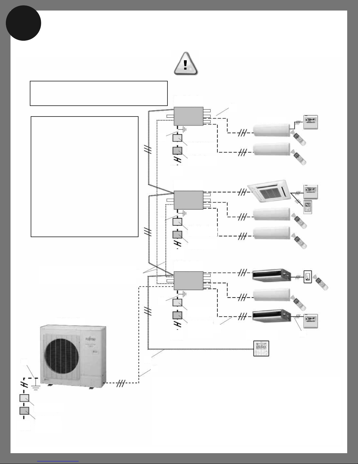
Basic Wiring Overview
Refer to installation manual for complete wiring and design criteria.
39,000 Btu Minimum connected capacity
62,000 Btu Maximum connected capacity
Outdoor Unit Electrical Requirements.
40A Breaker 8AWG 2+Ground
*Caution:
When installing this system in high humidity
locations, install using ground fault equipment
breakers (often referred to in other countries
as an ELCB earth leakage current breaker) to
reduce the risk of leaking current which may
result in electric shock or potential fire. We
suggest installing GFEB breakers or follow
local electrical code. This system uses an
inverter, which means that when used with a
ground fault breaker you must use breakers
that can handle higher harmonics such as a
(GFEB) Ground Fault Equipment Breaker
(30 mA or greater) in order to prevent
malfunctioning of ground fault device.
*
*
1 - Communication wires [Outdoor unit to Primary (Branch Box) B.B.]
2 - Communication wires [Primary B.B. to Secondary B.B.]
3 - Central remote controller wires [Central remote controller to B.B.]
4 - Power supply and Communication wires [B.B. to indoor units]
5 - Power supply [Outdoor unit]
6 - Power supply [Branch Box]
7 - Remote control wires [Indoor units to Remote Controller]
Branch Box 3
Secondary
Circuit Breaker
(over current)
Earth Leakage
Breaker*
Indoor Units
Power
Supply
Branch Box 2
Secondary
Circuit Breaker
(over current)
Earth Leakage
Breaker*
Power
Supply
Branch Box 1
Primary
Circuit Breaker
(over current)
Earth
Leakage
Breaker*
Power
Supply
Central Remote
Control
Outdoor Unit
Circuit Breaker
(over current)
Earth
Leakage
Breaker*
Power
Supply
5
1
3
4
7
6
2
6
8
6
WARNING!
Do not turn on power to system or branch boxes before
completing full evacuation and refrigerant charging!
Page 4
7
8
Copyright © Fujitsu General America, Inc.
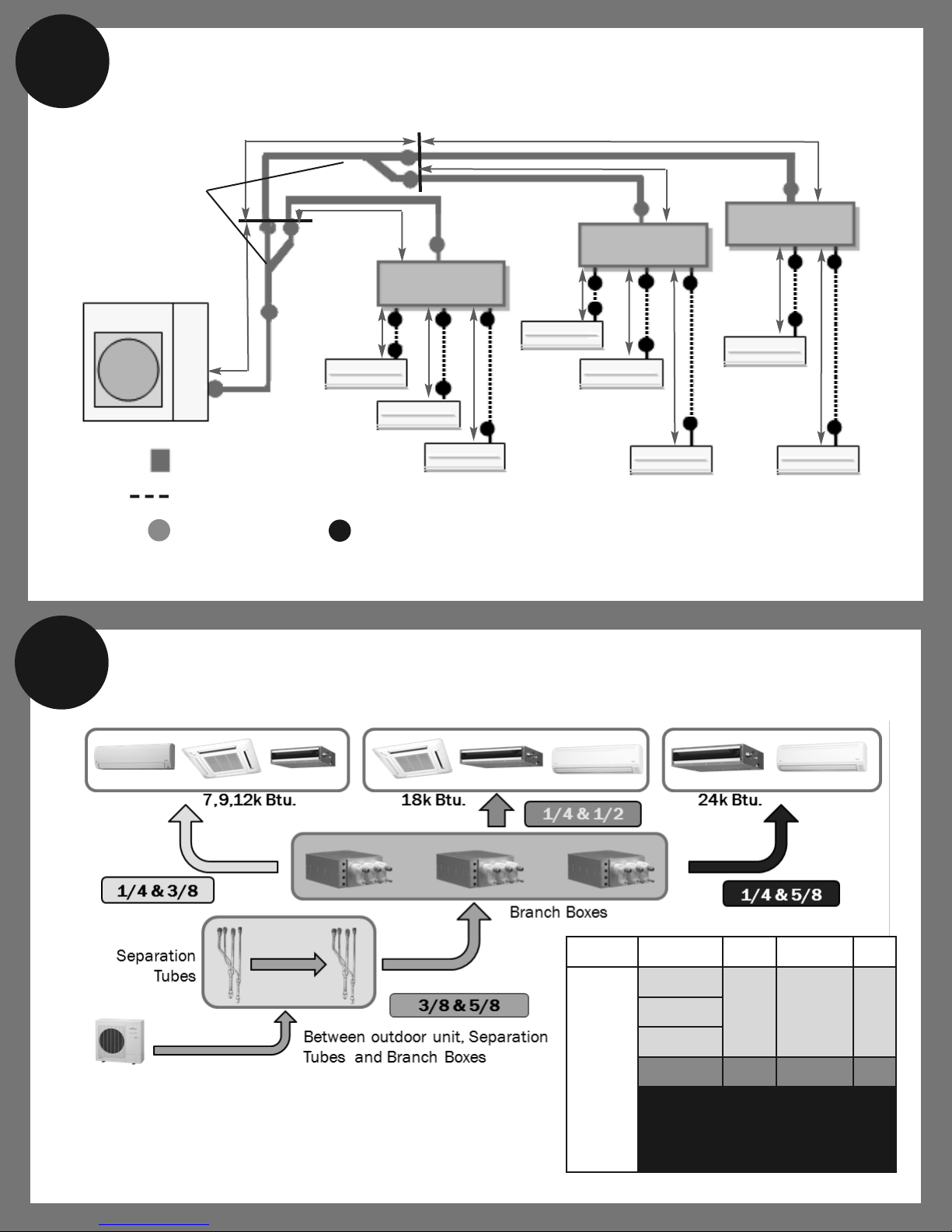
Piping Restrictions
Refrigerant Pipe Sizes
Liquid Adaptor Gas
Branch
Box
to
Indoor
Unit
7,000 BTU
1/4”
1/2” to 3/8”
adaptors
included
(3 of each)
3/8”9,000 BTU
12,000 BTU
18,000 BTU 1/4” 1/2”
24,000 BTU 1/4”
1/2” to 5/8”
adaptors
included
(3 of each)
5/8”
Outdoor Unit
Branch Box
Separation Tube
Assembly Kit
Liquid pipe 3/8 inch
Gas pipe 5/8 inch
=
Branch Box
Branch Box
Flare connections
=
Flare connections
=
Liquid pipe 1/4 inch
Gas pipe 3/8”, 1/2”, or 5/8”
based on indoor unit size*
=
*Branch box outlets are all 1/2” on gas pipe connections.
1/2” to 3/8” adaptors and 1/2” to 5/8” adaptors included (3 of each).
fgh
ijk
lm
a
b
c
e
d
Page 5
Copyright © Fujitsu General America, Inc.
10a
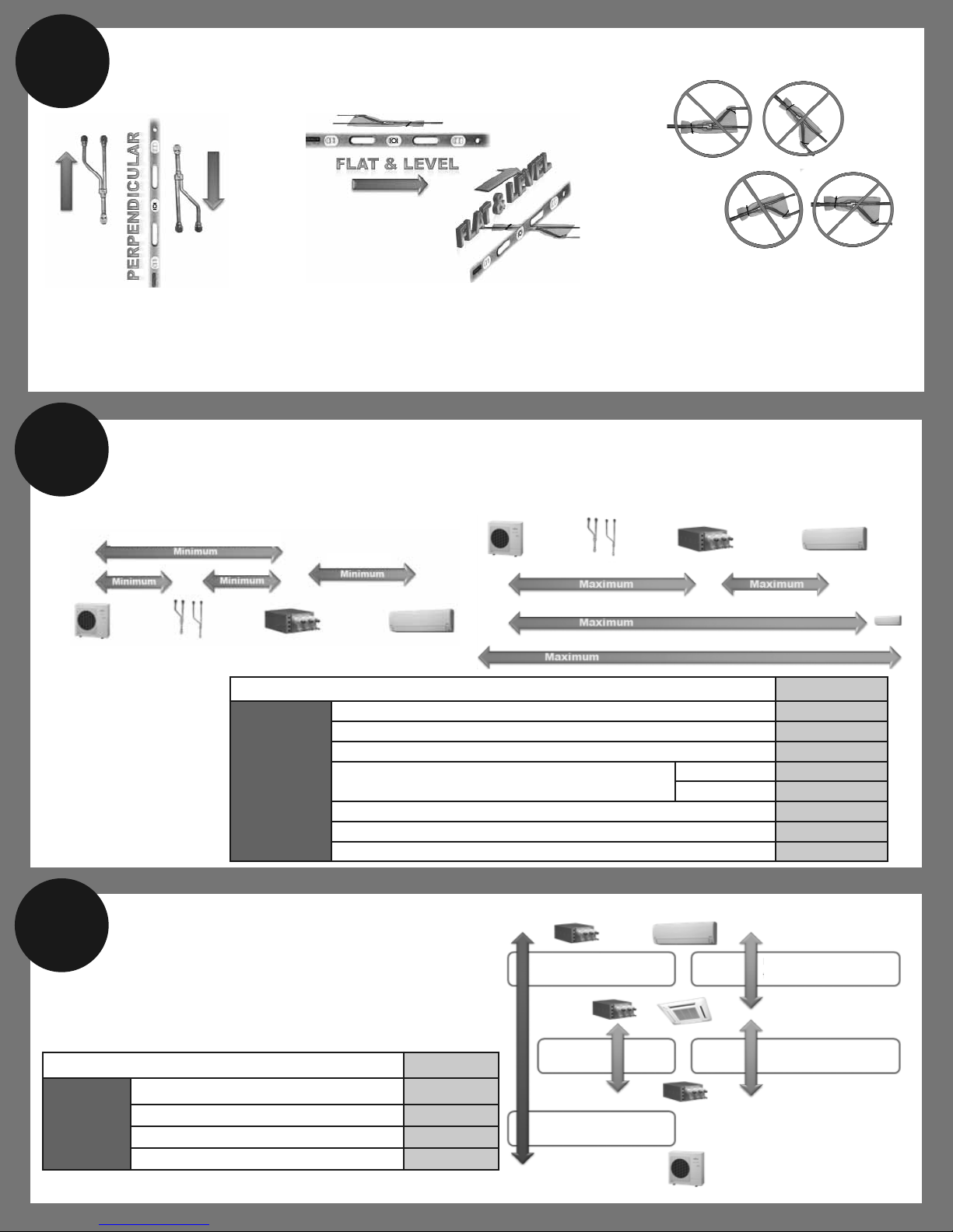
Pipe Length
Pipe Limitation Limitations
Allowable
pipe length
(actual pipe
length)
Total Pipe Length Up to 377 ft.
Between outdoor unit and the farthest indoor unit Up to 230 ft.
Between outdoor unit and branch boxes Up to 180 ft.
Between branch boxes and indoor unit
Total Up to 197 ft.
Ea. Unit 10 ft. to 49 ft.
Between outdoor unit and the first separation tube 16 ft. or more
Between outdoor unit and branch box (no separation tube) 16 ft. or more
Between outdoor unit and branch box (if separation tube used) 17 ft. or more
Vertical Positioning:
Tubes must stand straight up
or down. They CANNOT be
tilted or angled more than 10%
off perfectly vertical.
9
Horizontal Positioning:
Tubes must lay flat horizontal
They CANNOT be tilted or angled
more than 10% off Flat and Level
in either direction.
Separation Tube Assembly
Pipe Limitation Limitations
Allowable
height
difference
Between outdoor unit and indoor unit Up to 98 ft.
Between outdoor unit and branch box Up to 98 ft.
Between branch box and branch box Up to 49 ft.
Between indoor unit and indoor unit Up to 49 ft.
MINIMUM Allowable Pipe Lengths
MAXIMUM Allowable Pipe Lengths
Note: Pipe lengths must include fitting losses.
10b
Elevation
Maximum allowable height difference
Height = Elevation, not pipe length
16 Ft. Min. - if no separation tube
16 Ft. Min.
10 Feet Min.
180 Feet Max. 49 Feet Max.
230 Feet maximum to furthest indoor unit
377 Feet maximum connected pipe
98 Feet
49 Feet
98 Feet
49 Feet
Branch box to
branch box
49 Feet
Max to highest
branch box
From a branch box to its
highest indoor unit
From the lowest indoor unit
to the highest indoor unit
Max to highest
indoor unit
Outdoor unit can be above or
below evaporators
All indoor equipment must be
installed witihin the same 49 feet
of elevation from each other
1 Ft. Min.
197 Ft. Max Combined
Page 6

Copyright © Fujitsu General America, Inc.
12 13
11
Flaring
Insulation
Pipe Size Torque
• Cut pipe with a sharp tube cutter
• Deburr & clean out shavings
• Flare with quality tool
• Set depth properly for good flange
• Make sure nut pulls easily over flange not scraping threads.
Too big and it will leak.
• Place a thin film of correct refrigerant oil on male bevel.
• Hand tighten keeping line straight.
• Tighten correctly using a torque wrench according to the,
“Tightening torque” chart.
Pipe outside
diameter
in.(mm)
Dimension A
in. (mm)
Flare tool for
R410A, clutch type
Dimension B
in. (mm)
1/4 (6.35)
0 to 0.0197
(0 to 0.5)
23/64 (9.1)
3/8 (9.52) 33/64 (13.2)
1/2 (12.7) 21/32 (16.6)
5/8 (15.88) 25/32 (19.7)
Check if (L) is flared uniformly
and is not cracked or scratched.
Die
Pipe
Flare nut (lbf)
Tightening torque
1/4 - 16 to 18
3/8 - 32 to 42
1/2 - 49 to 61
5/8 - 63 to 75
Flare nut (N·m)
Tightening torque
6.35 - 142 to 159
9.52 - 283 to 372
12.70 - 434 to 540
15.88 - 558 to 664
Blank Cap
Flare Nut
Torque Wrench
Holding
Wrench
Torque
Wrench
All refrigerant pipes and connections
MUST BE INSULATED SEPARATELY
Gas Pipe
Connection Cable
Finishing Tape
Liquid Pipe
Heat Insulation
Gas Pipe
Liquid Pipe
Heat Insulation
Coupler Heat
Insulation (large)
Butting Surfaces
Coupler Heat Insulation (small)
Insulation (long)
Adhesive Tape
(field supplied)
Adhesive Tape
(field supplied)
Adhesive Tape
(field supplied)
Page 7

Copyright © Fujitsu General America, Inc.
15a 15b
14
Refrigerant Pipe - Example Layout
Equivalent
Pipe Length
To reduce the number of calculated feet always use smooth 6in. radius bends.
Note - Separation tubes
are installed in a Flat Horizontal or Vertical
position only!
For more information
refer to the installation
manual.
Primary
Secondary 1
Secondary 2
An onsite bend of less than 6 in. radius is
calculated at .35 Equivalent Feet.
Halcyon HFI system requires any bends tighter than a
6 in. radius to be counted as extra feet of pipe.
• Count the number of bends that have a less than 6 in.
radius ______(#)
• Multiply the number of bends by 0.35 = (Equivalent
Length)
• Add the Equivalent length to the actual feet of installed
line set = the calculated length.
3.5 feet added to actual length makes the
equivalent pipe length you must calculate
.
Example: (Your pipe sizes are 5/8 and 3/8)
A System with 5 bends each less than 6 in radius
between the outdoor unit and the 1st branch box.
5/8 - Multiply no. of bends 5 X 0.35 = 1.75(ft)
3/8 - Multiply no. of bends 5 X 0.35 = 1.75(ft)
Now add those 2 together to equal=
3.5 (ft)
When brazing:
Refer to the installation manual when using elbows or
hard pipe for pipe length calculation.
Page 8

16a 16b
Copyright © Fujitsu General America, Inc.
Branch Box
Layout
Branch Box Installation
• Factory Insulated Branch Boxes do not need a
condensate drain line or a drain pan.
• Incorrect installation will void warranty and may cause
electrical short in board.
• Suction line should always be on the top or side never
on the bottom in relation to the discharge line.
Electrical box is never on the bottom.
4 factory supplied hanger brackets allow for flexible
positioning.
Outlet
Side
Inlet
Side
VERTICAL
Vertical Wall Mount
• Can be hung from the ceiling or on the wall by
changing the location of hanger.
• Control box can be attached to the either side in
HORIZONTAL position only.
• Branch boxes do not have a weatherproof enclosure.
•
Cannot be mounted outside or in a space
above 80% relative humidity.
• May be installed in a storage space that is inside the
insulated envelope of the building.
Outlet
Side
Inlet
Side
CAUTION
• Do not hang from the ceiling when
performing a vertical installation.
• Secure the accessory hangers to the branch box
with the screws provided.
• Use 3/8 threaded rods with hexagonal nuts and
washers (field supplied) as shown on the figure.
• Make sure branch box is level before fastening the
nuts. (The unit’s slope must be within ±5° from
level.)
Branch box is marked with engraved letters indicating each
corresponding indoor unit (UNIT A, UNIT B and UNIT C).
UNIT A: Refrigerant pipe connection port for UNIT A
UNIT B: Refrigerant pipe connection port for UNIT B
UNIT C: Refrigerant pipe connection port for UNIT C
17
CAUTION
Label all the refrigerant piping
(liquid pipe, gas pipe) specifying
to which indoor units they will
be connected.
Threaded Rod
Washers
Nuts
Hanger brackets ship
with branch box
Page 9

Copyright © Fujitsu General America, Inc.
18 19
20
Leak Test
Evacuate
& Charge
Refrigerant Charge
YOU
MUST!
YOU
MUST!
Never apply power to a Fujitsu HFI system
until leak testing, repair, evacuation & the
refrigerant has been added to the system!
IMPORTANT NOTE:
R410a must be added to ALL Halcyon HFI Systems!
Charge is based on length of the liquid/small line side of the system’s pipes
- Total length in feet of liquid ⅜ (small) pipes from outdoor unit to Branch Boxes
- Total length of feet of liquid ¼ pipes from Branch Boxes to all indoor units
- Then add charge based on table below.
Calculate the refrigerant charge as follow:
• Multiply ⅜ calculated pipe length from outdoor unit
to branch boxes by .624 oz per ft.
• Multiply calculated ¼ pipe length Branch Boxes to
all Indoor Units by .224 oz per foot
Example: 78 ft calculated ⅜ pipe & 110 feet of calculated ¼ pipe
• ⅜@78ft X .624oz = 48.672oz divide oz by 16 to get 3.042lbs
• ¼@110ft X .224 oz = 24.64 oz = divide by 16 to get 1.54lbs
• Now Add ⅜ @ 48.672oz + ¼@ 24.64oz = 73.31oz – 4.58 lbs of R410a
Pipe Diameter Location Additional Refrig.
3/8” Outdoor to Branch Box 0.624 oz./ft. or 58g/meter
1/4” Branch Box to Indoor Unit 0.224 oz./ft. or 21g/meter
(Total length of 3/8” liquid line × 0.624 oz./ft. or 58g/meter ) + (Total length of 1/4” liquid line × 0.224 oz./ft. or 21g/meter )
(a+b+c+d+e) × 0.624 oz./ft. or 58g/meter + (f+g+h+i+j+k+l+m) × 0.224 oz./ft. or 21g/meter = additional refrigerant
Never apply power to a Fujitsu
HFI system until leak testing and
evacuation and system
refrigerant has been added!
• After completing nitrogen purge and
leak test slowly remove nitrogen
from the system
• Connect vacuum pump and
micron gauge
• Using industry standard “Best Practices”
evacuate system to 500 microns and
make sure it holds for 60 minutes.
• While evacuating calculate system charge
requirements.
• After connecting all refrigerant pipes connect
gauge hose and a regulated nitrogen tank to one connection of the
outdoor unit’s port and purge entire system with nitrogen through
the indoor units and back out the other port.
• Pressurize the entire piping system with nitrogen to 600PSI and
leak test every fitting carefully with soap bubbles!
• Perform a 24 hour standing pressure test with nitrogen to assure a
leak free system
• Keep service valves on the outdoor unit closed until system is
evacuated and refrigerant is added.
• It is highly recommended that you replace the oil in the vacuum
pump before it is used.
Page 10

Copyright © Fujitsu General America, Inc.
21a
Electrical Requirement - Outdoor Unit
Electrical Requirement - Branch Boxes
Secondary 2
Secondary 1
Primary
Communication Cable
3+Ground
Disconnect
Electrical Panel
Power Line
2+Ground
Communication Lines
Voltage Rating 1 Ø 208/230V (60Hz)
Operating Range 187 - 264V
Dedicated 208/230 40A
breaker for outdoor unit.
Cable Cable Size Remarks
Power Supply Cable 8 AWG 2 cable + Ground, 1 Ø 208/230V
Connection Cable 14 AWG 3 cable + Ground, 1 Ø 208/230V
Breaker Capacity (A)
HVACR Breaker* 40
Secondary 2
Secondary 1
Primary
Junction
Box
Disconnect
Electrical Panel
Power Line
2+Ground
Power Line
2+Ground
Connection Cable 3 wire and a ground (4 wires)
Voltage Rating 1 Ø 208/230V (60Hz)
Operating Range 187 - 264V
Dedicated 208/230 15A
breaker for branch box.
Cable Cable Size Remarks
Power Supply Cable 14 AWG 2 cable + Ground, 1 Ø 208/230V
Connection Cable 14 AWG 3 cable + Ground, 1 Ø 208/230V
Breaker Capacity (A)
HVACR Breaker* 15
* When installing this system in high humidity locations, install using ground fault equipment breakers (often referred to in other countries as an ELCB earth leakage
current breaker) to reduce the risk of leaking current which may result in electric shock or potential fire. We suggest installing GFEB breakers or follow local
electrical code. This system uses an inverter, which means that when used with a ground fault breaker you must use breakers that can handle higher harmonics
such as a (GFEB) Ground Fault Equipment Breaker (30 mA or greater) in order to prevent malfunctioning of ground fault device.
21b
Page 11

Copyright © Fujitsu General America, Inc.
22
Wiring Primary Branch Box
WARNING
• When replacing or servicing any branch
boxes, you must disconnect all power. This
can be done by disconnecting power at the
disconnect switch by the junction box and the
outdoor unit or tripping both breakers.
• Every wire must be connected firmly.
• No wire should be allowed to touch
refrigerant tubing, the compressor or any
moving part.
• Loose wiring may cause the terminal to over-
heat or result in unit malfunction. A fire
hazard may also exist. Therefore, be sure all
wiring is tightly connected.
• Connect wires to the matching numbers of
terminals.
Power Supply line 1 phase,
208/230, MCA 40 Amp
Disconnect Switch*
Field Supplied
Page 12

Copyright © Fujitsu General America, Inc.Copyright © Fujitsu General America, Inc.
Electrical Connection
Primary Branch Box to Branch Box A
24
Secondary Branch Box A
Secondary Branch Box B
Primary Branch Box
Secondary Branch Box A
• Power Wire = 14/2 with Ground
• Control Wires = 14/3 + Ground wire (4 wires)
• Master Remote Wire = 3 wire 20 Ga. stranded
Electrical Connection
Primary Branch Box
23
Page 13

Copyright © Fujitsu General America, Inc.
27 28a
25
26
Electrical
Connections
Before Turning
On Power
Pre-Start-Up
Checklist
Check Operation
(1) Turn on power to
the outdoor unit,
indoor units and
branch boxes.
(2) Press and hold the
CHECK button for
approximately 5
seconds.
(3) The number of
connected branch
boxes and internal
units will be displayed
on the display. Check
that the displayed
number matches the
actual number of
connected units.
LED Display
LED Display
Stranded Wire Shown
Solid or Stranded Wire
1. Was the system leak tested, purged with nitrogen and
evacuated?
2. Have all refrigeration lines been insulated separately?
3. Was the correct amount of refrigerant added? All HFI
systems require the addition of refrigerant
4. Is the system electrical supply all connected according
to instructions and codes?
5. Are all system electrical connections tight?
6. Have the service valves been opened on the outdoor
unit?
Copyright © Fujitsu General America, Inc.
Perform the Check Operation - auto diagnostic function
- See installation manual before running Check Operation
system function.
ALWAYS PERFORM THE CHECK OPERATION.
NORMAL OPERATION WILL NOT BE POSSIBLE
WITHOUT PERFORMING THE CHECK OPERATION.
If you attempt Test Run or system operation "FAIL" is
displayed when operating the unit before the check
operation is completed. Once the Check Operation has
been performed put system in Test Run mode.
Before finishing:
Confirm operation of each indoor unit individually
- Check for cool or warm air flow depending on mode
- Confirm air flow and louver operation
- Make sure all remotes operate the units
Read actual installation manual for complete details
on the operating conditions and limitations during
“check operation.”
Page 14

Copyright © Fujitsu General America, Inc.
29 30
28b
28c
Test Run
Test Run Setting
(4) Press and hold the
CHECK button again
for approximately 5
seconds. The Check
operation will start.
(5) Check operation
will stop automatically.
If you MUST stop the
system, press the
MODE/EXIT button.
connected units.
Operating in Check
Run Mode
Check operation will stop automatically when done.
You cannot execute the stop operation using the
remote control.
When you’ve completed this step, power
needs to be reset.
When an error occurs, consult the
installation manual for complete
instructions following error display.
• During test run, the outdoor unit and the connected
indoor units will start operating. Room temperature
control along with the remote controller commands will
be ignored during test run.
• Test run set with the outdoor unit doesn't stop
automatically. Be sure to stop the Test Run to place
the system in normal operation cooling/heating.
• Operation mode cannot be changed during the test run.
To change the operation mode, please stop test run first.
Perform after successful Check
Operation (28a) above.
Test run is not
possible during
an error code
condition.
Refer to the installation
manual for all error codes
and repair instructions.
• Press Mode/Exit button
• Press Select button until
F3 appears
• Press Enter
• Select “00”
• Press Enter
Press the “MODE/EXIT” button.
Press the “SELECT” button.
Press the “ENTER” button.
(When [F4] to [F9] are displayed, continue to press
the SELECT button until [F3] is displayed.)
MODE/EXIT
SELECT
ENTER
OPERATION HAS FINISHED
NORMALLY WITHOUT ERROR.
Copyright © Fujitsu General America, Inc.
Page 15

Copyright © Fujitsu General America, Inc.
31 32
33
Start Test Run
for Cooling
Stop Test Run
Homeowner Information
When setting
for test run
are complete
it will display
“done” on the
LED and test
run will
commence.
To stop Test Run:
• Press Select until “02” is displayed
• Press Enter
Refer to the
installation manual
for heating test run
mode and the
different operating
conditions.
After test run is complete, turn off the power. Then
replace the cover of the electrical component box and
the front panel of the outdoor unit.
Things to review with the home owner – from the
Operation Manual.
- Wireless remote controls will need 2 AA batteries seasonally
depending on use.
- Filters will need to be cleaned in all indoor units on a monthly basis.
- Regular seasonal maintenance is required including washing of
outdoor coils.
• ECONOMY OPERATION
• MINIMUM HEAT OPERATION
• CLEANING AND CARE
• DEFROST OPERATION
Run the units in normal modes and
confirm operation.
Operating Modes
AUTO .............................64-88°F
Heating ..........................60-88°F
Cooling/Dry ....................64-88°F
Simultaneous Use of Multiple Indoor Units:
1. This system has a 100% capacity of 48,000 BTUs.
2. Whether you connect a total of 48,000 BTUs of indoor
units or you connect up to 62,000 BTUs of indoor units,
the system will only provide a total of 48,000 BTUs of
capacity.
3. If you operate indoor units over 100 percent of capacity up
to 62,000 BTU’s at the same time, each indoor capacity
will be reduced. The total capacity delivered will be
48,000 BTU.
4. When using connectable capacity above the rated 100%
of the outdoor unit’s BTU capacity cycle the indoor units to
increase the desired indoor unit’s capacity to its rated BTUs.
Outdoor Unit Operating Range:
Cooling 25 to 115°F (-5 to 46°C)
Heating 5 to 75°F (-15 to 24°C)
Example: When set to 80°F
Copyright © Fujitsu General America, Inc.
Page 16

Copyright © Fujitsu General America, Inc.
Fujitsu General America, Inc.
353 Route 46 West
Fairfield, NJ 07004
Toll Free: (888) 888-3424
Local: (973) 575-0380
Fax: (973) 836-0447
Email: hvac@fujitsugeneral.com
www.fujitsugeneral.com
A subsidiary of
Fujitsu General Limited
Printed in the USA Rev. 7/10
Warning
Always use a licensed installer or contractor to install this product. Do not
try to install the product yourself. Improper installation can result in water
or refrigerant leakage, electrical shock, fire or explosion. Use only parts
and accessories supplied or specified by Fujitsu. Ask a licensed
contractor to install parts and accessories. Use of unauthorized or
improper installation of parts and accessories can result in injury or
property damage. Read the owner's operation manual carefully before
using this product. The owners operation manual provides important
safety instructions and warnings which should be followed closely. For
any questions or concerns, please contact Fujitsu General America, Inc.
Trademarks
The Fujitsu logo is a registered trademark of Fujitsu Limited.
The Halcyon logo and name is a trademark of Fujitsu General America, Inc.
Copyright © 2010 Fujitsu General America, Inc.
Fujitsu’s products are subject to continuous improvements. Fujitsu reserves
the right to modify product design, specifications and information in this
brochure without notice and without incurring any obligations.
Complete System Warranty
All 2010 Halcyon HFI Systems have a warranty of:
5 Year Parts, 7 Year Compressor Warranty.
Note: Condensing units come pre-charged from factory.
Additional refrigerant may be required, be sure to check installation manual for
more details.
• Cooling capacity is based on the following conditions:
Indoor temperature: 80°F DB/67°F WB (26.7°C DB/19.4°C WB)
Outdoor temperature: 95°F DB/75°F WB (35°C DB/23.9°C WB)
• Heating capacity is based on the following conditions:
Indoor temperature: 70°F DB (21.1°C DB)
Outdoor temperature: 47°F DB/43°F WB (8.3°C DB/6.1°C WB)
Non-Internet Retail Policy
Internet sales are strictly prohibited and unauthorized. Any HVAC
systems purchased on the Internet, from an online retailer or any similar
e-tailing website, OR where the original factory serial numbers of the
display have been removed, defaced, or replaced in any way WILL NOT
BE COVERED BY WARRANTY.
 Loading...