

Page 1
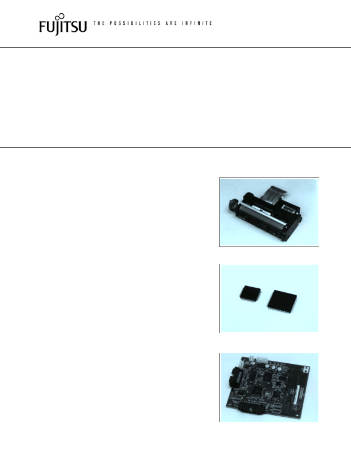
BATTERY DRIVE, MICRO LINE THERMAL PRINTER
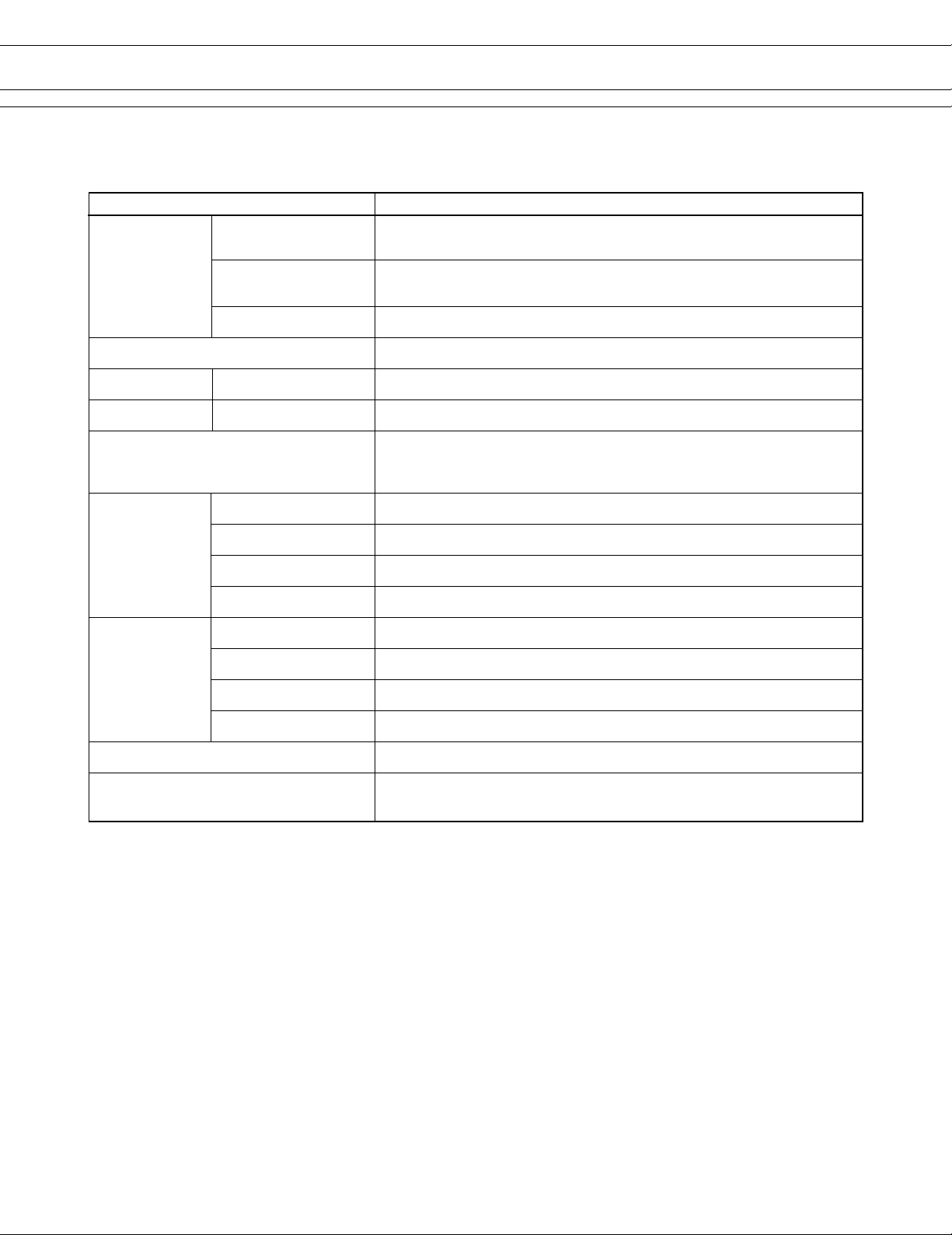
3” TYPE MECHANISM AND INTERFACE BOARD
FTP-633MCL400/FTP-623DCL002
■ OVERVIEW
This battery driven, micro line thermal printer offers high speed
printing for 3-inch wide paper (70 mm). It is suitable for portable
equipment that requires compact, lightweight components.
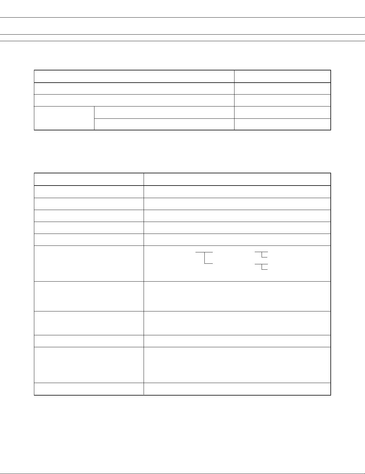
In addition to the interface board, a driving LSI (MCU + Gate
Array) is also available.
■ HIGHLIGHTS
• Driven by batteries (direct connect between thermal
head and batteries)
It can be driven by a broad range of voltages (4.2 to 8.5 V) of
NiCd or Nickel-Hydrogen by using Fujitsu Components'
unique head drive control system. The battery pack can be
connected directly to the print head without a voltage
regulator. Also, a lithium-ion battery can be applied.
• High speed printing
It can print at approximately 24 character lines/s (460
dotlines/s = 60 mm/s).
• Compact and lightweight
It has a light weight of approximately 84 g.
• Low power consumption
The peak current for head driving is approximately 3.0 A.
• Selectable paper paths
Front, rear and top paper insertion paths can be used.
• Paper auto loading function
Paper feeding is enabled by operating the head up lever.
• Variety of suitable paper
This model is capable of printing on a variety of papers,
including 1-ply roll paper, 2-ply paper (TCC and roll), labels,
and long-life paper.
FTP-633MCL400
FTP-623CU001, FTP-633GA101
FTP-623DCL002
1
Page 2
■ DESIGNATION
FTP-633MCL400/FTP-623DCL002
Item
Printer mechanism
Interface board
Micro Controller Unit
LSI
Gate Array
*: Rear paper insertion type is available: FTP-633MCL402
■ GENERAL SPECIFICATIONS
SpecificationsItem
Printing method Thermal-sensitive line dot method
Dot structure 512 dots/line
Dot pitch (Horizontal) 0.125 mm (8 dots/mm)—Dot density
Dot pitch (Vertical) 0.125 mm (8 dots/mm)—Line feed pitch
Effective printing area 64 mm
Part number
FTP-633MCL400*
FTP-623DCL002
FTP-623CU001
FTP-633GA101
(1) Single density Standard mode HS mode 1. to 3.
Printing mode Reduced mode HS mode 1. to 3.
(2) Double density mode
Approximately 24 character lines/s (480 dotlines/s = 60 mm/s)
Maximum printing speed
Character types Semi-graphic : 36 International characters : 130
Character grade mode Standard character (12 × 6 dot font)/High grade character (16 × 8 dot font)
Character composition, dimensions (H×W),
Number of columns (standard)
Interface 1) Centronics standard 2) Bus interface*
[1ply, 8 columns of “H”, double density, 7.2 V, 1/10” line returns]
Approximately 16 character lines/s (416 dotlines/s = 52 mm/s)
[1ply, 12 columns of “H”, double density, 7.2 V, 1/8” line returns]
JIS ANK : 128 ASCII : 31
Special : 30 Download : 8
Single density standard : 24 × 12 dots, (3.0 × 1.5 mm), 42 columns
Single density reduced*
Double density : 16 × 8 dots, (2.0 × 1.0 mm), 64 columns
32 × 16 dots, (4.0 × 2.0 mm), 32 columns
1
: 24 × 12 dots, (3.0 × 1.5 mm), 42 columns
32 × 16 dots, (4.0 × 2.0 mm), 32 columns
HQ mode
HQ mode
2
(Continued)
2
Page 3
FTP-633MCL400/FTP-623DCL002
(Continued)
SpecificationsItem
For print head
Operating
voltage
Weight Mechanism: approximately 84 g. Interface board: approximately 60 g
For motor
For logic 5 VDC ± 5%, 0.15 A
4.2 to 8.5 VDC (4 or 5 Ni-Cd or Ni-MH batteries, equivalent to 2 Li-ion)
Approximately 3.0 A (peak value, 7.2 V, 100% printing ratio)
4.2 to 8.5 VDC (4 or 5 Ni-Cd or Ni-MH batteries, equivalent to 2 Li-ion)
Average 0.7 A or less
Printer mechanism
Interface board Dimensions 108 (W) × 91 (D) × 18 (H) mm
Thermal head life
Environmental
conditions
Detection Paper out/Mark detect By photointerrupter (command set)
Paper width 70 mm
Recommended thermal sensitive paper
Dimensions 85 (W) × 49 (D) × 20 (H) mm (excluding knob, lever, and flexible PC board)
Pulse durability : 1 × 10⁸ pulse/dot (using Fujitsu Takamisawa's standard
Wear resistance: 50 km (at 25% printing ratio)
Operating temperature +5 to +40°C*
Operating humidity 20 to 85% RH (no condensation)
Storage temperature –20 to +60°C (excluding paper)
Storage humidity 5 to 95% RH (no condensation)
Head temperature By thermistor
Voltage By micro controller
Head-up By microswitch
+0
–1
1 ply (roll) : FTP-030PG021 Long life (roll) : FTP-030PR202
2 ply (TCC) : FTP-030P8021
driving method)
3
*1: Character composition for single density reduced mode is the same as for single density standard mode.
*2: The data to be printed is automatically read out by the printer driver equipment memory (host system frame
memory). The communication is parameter transfer.
*3: Temperature range for guaranteed printing density. It can be operated in the range of 0 to +40°C.
3
Page 4
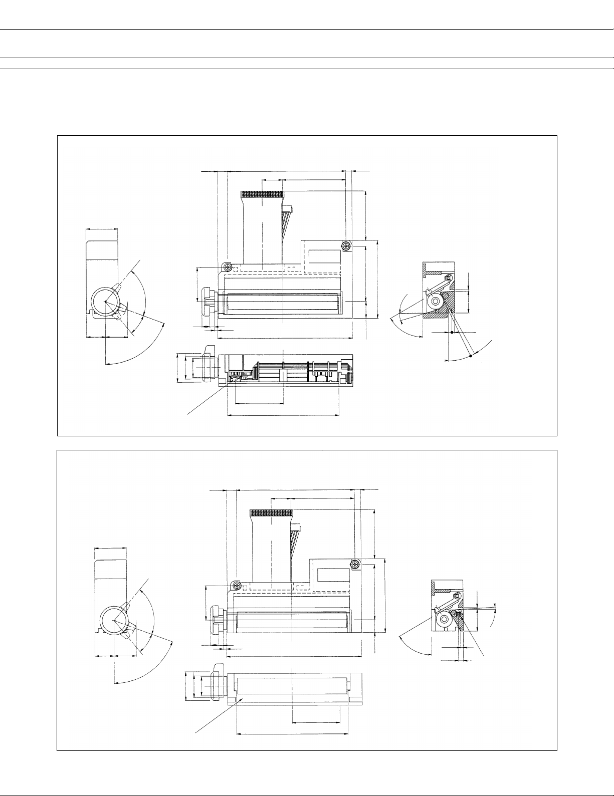
■ DIMENSIONS
Printer mechanism
FTP-633MCL400
6.1
FTP-633MCL400/FTP-623DCL002
74.5
12.5 40
3.9
20
(3)
70°
12 (14)
(1): Head down
(2): Paper feed
(3): Head up lock
30°
(2)
70°
FTP-633MCL402
21.5
(1)
Photo interrupter
(ø18)
ø12
(ø14)
5
3
2
(Photo interrupter)
6.1
Paper center
85
30
70.2 (Paper insertion)
74.5
12.5 40
(31)
34.5
10.5
3.9
49
16°
60°
Paper out
angle
1.0
4°
13.7
1.7
2.3
3°
26°
Unit: mm
Front and top insertion type
20
(3)
12 (14)
(1): Head down
(2): Paper feed
(3): Head up lock
30°
(2)
70°
(1)
70°
21.5
5
ø12
(ø14)
(ø18)
Photo interrupter
(31)
34.5
46
3
2
Paper center
85
30
(Photo interrupter)
70.2 (Paper insertion)
7.5
60°
Paper out
angle
(Photo
interrupter)
1.0
4°
4°
13.7
1.7
3.1
Photo
interrupter
Rear insertion type
Unit: mm
4
Page 5
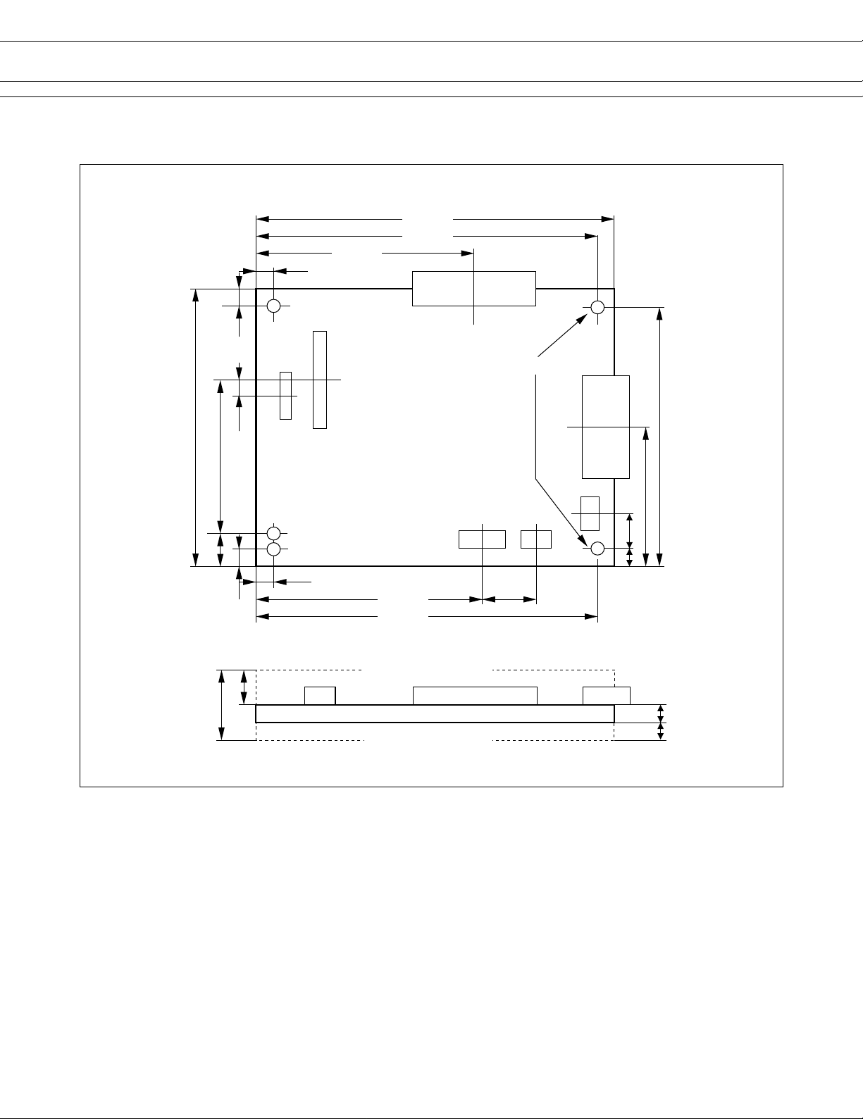
Interface board
5.1
5.1
FTP-633MCL400/FTP-623DCL002
108.0
102.9
69.8
CN5
90.2
46.5
10.0
17.6
4.6
5.1
10.0
CN8
5.1
CN7
CN2 CN1
73.7
102.9
Height of devices side
Height of solder side
ø3.6
85.1
CN4
42.5
CN6
13.3
5.1
16.5
1.6
6.0
Unit: mm
5
Page 6

FTP-633MCL400/FTP-623DCL002
■ INTERFACE
1. Centronics standard
(1) Connector
Connector part number : FCN-215Q030-G/0 (Fujitsu Components) or equivalent
Mating connector part number : FCN-217Q030-G/0 (Fujitsu Components) or equivalent
FCN-214Q030-G/0 (Fujitsu Components) or equivalent
FCN-215Q030-G/0 (Fujitsu Components) or equivalent
(2) Connector pin assignment
No. Signal I/O Contents No. Signal I/O Contents
1 PRSTB I Data strobe 2 PRSTB-RET —
3 PRDT0 I Data 0 4 PRDT0-RET —
5 PRDT1 I Data 1 6 PRDT1-RET —
7 PRDT2 I Data 2 8 PRDT2-RET —
9 PRDT3 I Data 3 10 PRDT3-RET —
11 PRDT4 I Data 4 12 PRDT4-RET —
13 PRDT5 I Data 5 14 PRDT5-RET —
15 PRDT6 I Data 6 16 PRDT6-RET —
17 PRDT7 I Data 7 18 PRDT7-RET —
19 ACKNLG O Data input acknowledge 20 ACKNLG-RET —
21 BUSY O Busy 22 BUSY-RET —
23 RINF2 O Printer status 24 INPRM-RET —
Connected to logic GND
Connected to logic GND
Connected to logic GND
Connected to logic GND
Connected to logic GND
Connected to logic GND
Connected to logic GND
Connected to logic GND
Connected to logic GND
Connected to logic GND
Connected to logic GND
Connected to logic GND
25 SLCTIN I Printer select 26 INPRM I Reset
27 RINF1 O Printer status 28 RINF3 O Printer status
29 ATF I Paper feed request 30 GND — Logic GND
Notes:
• Symbol “——” means a negative logic signal.
• “–RET” signal is a return signal of the twisted pair cable.
• “I” or “O” means a signal direction from the interface board side.
(3) Connector pin number
FCN-215Q030-G/0 (Fujitsu Components) or
equivalent
3
291
230
(4) Data input signal timing
PRDT0~7
PRSTB
BUSY
ACKNLG
Data set time
PRSTB pulse width
Data hold time
PRSTB to BUSY= “H”
ACKNLG pulse time
t1 t3
t2
t4
:t1≥0.5 µsec
:t2≥0.5 µsec
:t3≥0.5 µsec
:t4≤0.5 µsec
:t5=1.0~1.5 µsec
t5
6
Page 7

FTP-633MCL400/FTP-623DCL002
2. Bus interface
(1) Connector
Connector part number : FCN-215Q040-G/0 (Fujitsu Components) or equivalent
Mating connector part number : FCN-217J040-G/0 (Fujitsu Components) or equivalent
: FCN-214J040-G/0 (Fujitsu Components) or equivalent
: FCN-215J040-G/0 (Fujitsu Components) or equivalent
(2) Connector pin assignment
No. Signal I/O Contents No. Signal I/O Contents
1 ALE O Address latch 2 BRD — Data read
3 BWR — Data write 4 READY — Data access ready
5 HACK — Hold acknowledge 6 HRQ — User hold request input
7 MCRC — Power-down (not used) 8 CLK O System clock
9 PCPAK1 O
11 PCPSD1 I Common RAM reading request 12 PRON O Printer operating
13 RST I Hard reset 14 GND — Ground
15 DB00 I/O External address/Data bus 0 16 DB01 I/O External address/Data bus 1
17 DB02 I/O External address/Data bus 2 18 DB03 I/O External address/Data bus 3
19 DB04 I/O External address/Data bus 4 20 DB05 I/O External address/Data bus 5
21 DB06 I/O External address/Data bus 6 22 DB07 I/O External address/Data bus 7
23 AB08 O External address bus 08 24 AB09 O External address bus 09
25 AB10 O External address bus 10 26 AB11 O External address bus 11
27 AB12 O External address bus 12 28 AB13 O External address bus 13
29 AB14 O External address bus 14 30 AB15 O External address bus 15
31 AB16 O External address bus 16 32 AB17 O External address bus 17
33 AB18 O External address bus 18 34 AB19 O External address bus 19
35 AB20 O External address bus 20 36 AB21 O External address bus 21
37 AB22 O External address bus 22 38 AB23 O External address bus 23
Common RAM reading completion
10 ATF I Automatic paper loading
39 RAM2 O Common RAM access 40 INPRM I Reset
Notes:
• Symbol “——” means a negative logic signal.
• “I” or “O” means a signal direction from the interface bpard side.
7
Page 8
FTP-633MCL400/FTP-623DCL002
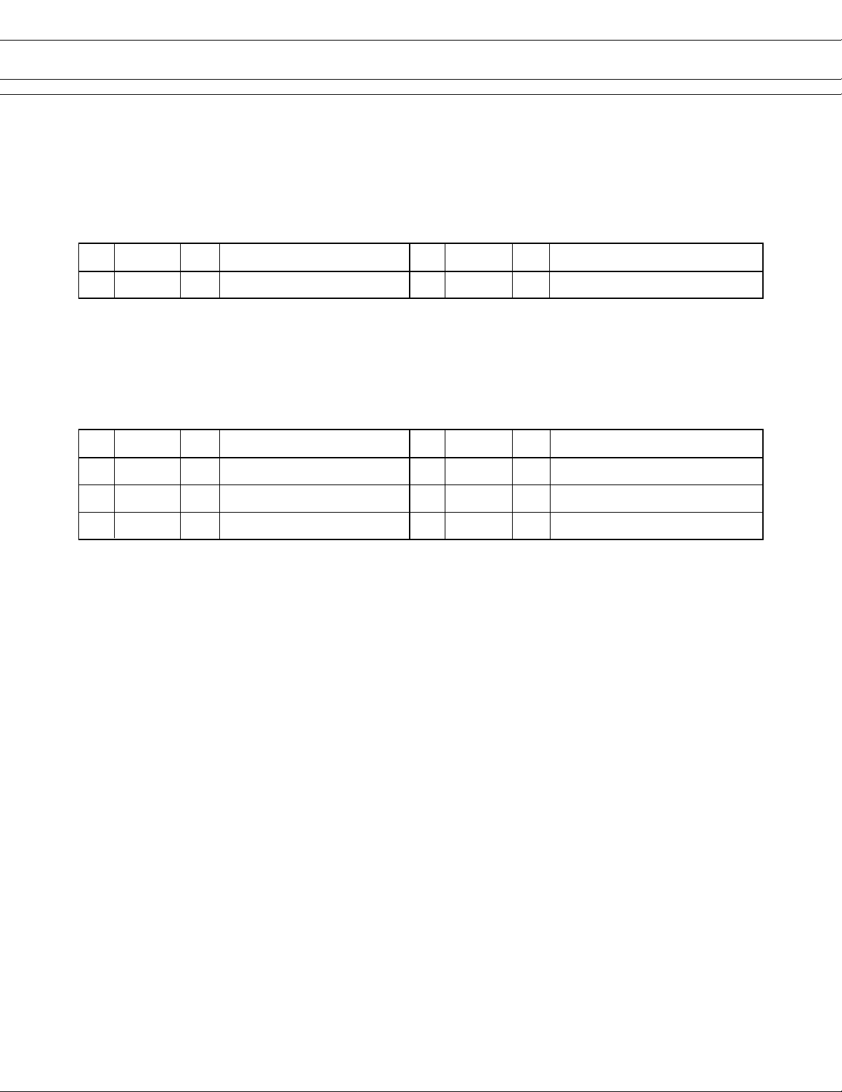
■ CONNECTOR PIN ASSIGNMENT
1. Connector for logic power supply (CN1)
Part number : B4B-XH-A-WHITE (J.S.T) or equivalent → P.C.B side
Mating connector part number : XHP-4 (J.S.T) or equivalent → Cable side
No. Signal I/O Contents No. Signal I/O Contents
1VCC — Power supply for logic (+5V) 2 GND — Logic ground
2. Connector for thermal head and motor power supply (CN2)
Part number : B6B-XH-A-WHITE (J.S.T) or equivalent → P.C.B side
Mating connector part number : XHP-6 (J.S.T) or equivalent → Cable side
No. Signal I/O Contents No. Signal I/O Contents
1 BAT — Power supply for head/motor 2 BAT — Power supply for head/motor
3 BAT — Power supply for head/motor 4 GND — Head/motor ground
5 GND — Head/motor ground 6 GND — Head/motor ground
8
Page 9

FTP-633MCL400/FTP-623DCL002
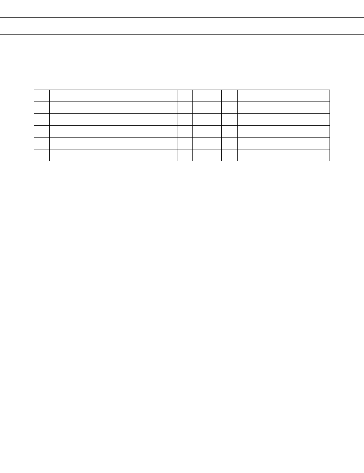
3. Connector for thermal head drive (CN7)
Part number : 52030-2610 (Molex) or equivalent → P.C.B side
No. Signal I/O Contents No. Signal I/O Contents
1 BAT — Power for head 2 BAT — Power for head
3 GND — Head ground 4 GND — Head ground
5 HD2 O Print data output 6 LAT O Printing data latch
7 HDV O Power for logic 8 HCLK O Printing transmitting clock
9 ENB8 *
11 ENB6 O Printing enable 12 ENB5 O Printing enable
13 VREF O Power for thermistor 14 TMP O Temperature detection
15 *
17 *
19 *
1, 2
O Printing enable 10 ENB7 *
3
— Connected with No. 17 16 HDV O Power for logic
3
— Connected with No. 15 18 *
4
— Not used (pulled-up by resistor) 20 ENB4 O Printing enable
1, 2
— Printing enable
4
— Head rank specify (not used)
21 ENB3 O Automatic paper loading 22 ENB2 O Printing enable
23 ENB1 O Printing enable 24 GND — Paper-out detection
25 GND — Printing enable 26 BAT — Power for head
Notes:
*1: Mechanism selection signal and the printing enable signal for 3” mechanism.
*2: Not used at the combination with 2” mechanism.
*3: At the mechanism side, this pin number is for the printing data 2.
Since this pin number is used for the printing data 1 at the inter face board, the No. 15 and No. 17 pins are
connected.
*4: This signal is used for the adjustment of printing duty depending upon the rank of thermal head resistor. Not
used at this interface board.
• Symbol “——” means a negative logic signal.
• “I” or “O” means a signal direction from the interface board side.
4. Connector for abnormal head temperature detection (CN6)
Part number : B3B-XH-A-WHITE (J.S.T) or equivalent → P.C.B side
Mating connector part number : XHP-3 (J.S.T) or equivalent → Cable side
No. Signal I/O Contents No. Signal I/O Contents
1 TMPER O
3 GND — Logic ground
Abnormal head temperature detection
2 N.C. — Not connected
Note: This signal detects abnormal head temperature.
9
Page 10
FTP-633MCL400/FTP-623DCL002
5. Connector for stepping motor drive (CN8)
Part number : B10B-ZR (J.S.T) or equivalent → P.C.B side
Mating connector part number : ZHR-10 (J.S.T) → Mechanism side
No. Signal I/O Contents No. Signal I/O Contents
1 HUP I Head up detection 2 VCC — Power for switch
3 PINCH I Paper auto loading detection 4 SDV — Power for photointerrupter
5 SLED — Power for diode cathode 6 PES I Paper out detection
7 MT/B0 O Stepping motor coil excitation (B) 8 MT/B0 O Stepping motor coil excitation (B)
9 MT/A0 O Stepping motor coil excitation (A) 10 MT/A0 O Stepping motor coil excitation (A)
10
Page 11

FTP-633MCL400/FTP-623DCL002
■ PRINTING COMMANDS (CENTRONICS STANDARD INTERFACE)
Name Command Contents
Carriage return LF, CR Prints buffer data and return the line.
Double width print set SO Sets the double width character.
Power-down mode set DC2, DC3 Reduces the power consumption during standing
by.
Double width print reset DC4 Resets the double with character.
ESC sequence entry ESC Indicates the start of an escape sequence formed
Line space set ESC A + n Sets the line space length in 2 × (0 to 255 dot
Paper feed set in normal direction ESC B + n Sets the paper feed in normal direction.
Bit image print set ESC K +n1+n2+n3 Sets the bit image printing in single or double
International character set ESC R+n Selects the international characters.
Download character register ESC &+n1+n2+~ Registers the download characters of 12 × 6 or 16
Printing quality set ESC Q+n+SP*+~ Sets the printing quality conforming to used paper.
Printing density set ESC Q+n+!+A Sets the printing density mode.
Paper feed set in reverse direction ESC j+n Sets the paper feed in reverse direction.
Character grade set ESC x+n Sets the character grade in standard or high
by this code plus subsequent commands.
lines).
(Feeding range: 2 × (0 to 255 dot lines))
density mode.
× 8 dots.
(Single density standard, reduced or double
density)
(Feeding range: 2 × (1 to 255 dot lines))
grade.
Special character print set ESC ¥+n Prints the special character.
Start position set for bit-image printing ESC 1+n Sets the print start position of bit-image printing in
left end.
Detecting function set ESC 9+n Sets the detecting function.
Mark detection ESC FF Feeds the paper to the marking position.
Line feed length set after mark detection ESC w+n Sets the line feed length after mark detection.
Automatic paper loading length set ESC EM+n Sets paper feeding length for automatic paper
loading.
Automatic printing speed set ESC s+n Sets the function mode in the automatic printing
speed set.
Printer initialization ESC @ Initializes the printer MPU.
Notes:
*: “SP” means the space code (20H).
Bus interface uses different commands.
11
Page 12
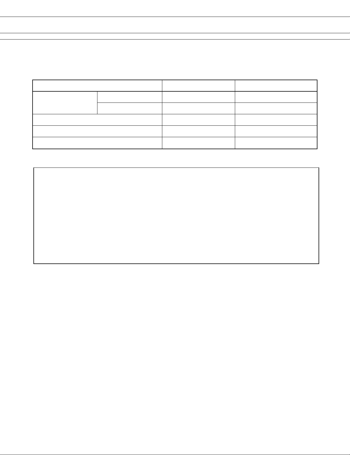
■ OPTIONS
1. Cable
FTP-633MCL400/FTP-623DCL002
Name Part number Cable length
Interface cable
For Centronics FTP-621Y202 500 mm
For Bus I/F FTP-621Y203 500 mm
Power supply cable (A): for logic motor FTP-621Y401 300 mm
Power supply cable (B): for thermal head FTP-621Y601 300 mm
Head abnormal temperature detection cable FTP-621Y204 300 mm
Europe
Fujitsu Components Europe B.V.
Diamantlaan 25
2132 WV Hoofddorp
Netherlands
Tel: (31-23) 5560910
Fax: (31-23) 5560950
Email: info.marketing@fceu.fujitsu.com
Web: www.fceu.fujitsu.com
Asia Pacific
Fujitsu Components Asia Ltd.
102E Pasir Panjang Road
#04-01 Citilink Warehouse Complex
Singapore 118529
Tel: (65) 375-8560
Fax: (65) 273-3021
Email: fcal@fcal.fujitsu.com
www.fcal.fujitsu.com
Fujitsu Components
International
Headquarter
Offices
Japan
Fujitsu Component Limited
Gotanda-Chuo Building
3-5, Higashigotanda 2-chome, Shinagawa-ku
Tokyo 141, Japan
Tel: (81-3) 5449-7010
Fax: (81-3) 5449-2626
Email: promothq@ft.ed.fujitsu.com
Web: www.fcl.fujitsu.com
North and South America
Fujitsu Components America, Inc.
250 E. Caribbean Drive
Sunnyvale, CA 94089 U.S.A.
Tel: (1-408) 745-4900
Fax: (1-408) 745-4970
Email: marcom@fcai.fujitsu.com
Web: www.fcai.fujitsu.com
© 2001 Fujitsu Components America, Inc. All company and product names are trademarks or registered
trademarks of their respective owners. Rev. 09/2001
12
 Loading...