

Page 1
Page 2

DSL Modem Installation Guide
Issue 2, Rev 2, February 2000
FJTU-320-600-900
Copyright© 2000 Fujitsu Network Communications, Inc. All Rights
Reserved.
This document, and its contents areprovided by Fujitsu Network
Communications, Inc. (FNC) for guidance purposes only. This document is
provided “as is” with no warranties or representations whatsoever, either
express or implied, including without limitation the implied warranties of
merchantability and fitness for purpose. FNC does not warrantorrepresent
that the contentsof this document are error free. Furthermore,the contents
of this document are subject to up date and change at any timewithout notice
by FNC, since FNC reserves the r ight, without notice, to make changes in
equipment design or components as progress in engineering methods may
warrant.No part of the contents of this document may be copied, modifiedor
otherwise reproduced without the express written consent of FNC.
Page 3

Safety Information
Safety Warnings
Potentially hazardous voltages exist within this unit. Always o bserve
standard safety precautions and also the safety warnings in this guide
duringinstallation,operation, and maintenanceof this product. There are no
user provisionable options.
FCC Warning
This equipment has been tested and f ound to comply with the limits for a
Class B digital device, pursuant to Part 15 of the FCC Rules. These limits
are designed to provide reasonable protection against harmful interference
when the equipment is operated in a residential environment. This
equipment generates, uses, and can radiate radio frequency energy and, if
not installed and used in accordancewith the instructionmanual, may cause
harmful interference to radio communications. However, there is no
guarantee that interferencewill not occur in a particular installation. If this
equipment does cause harmful interferenceto radio or television reception,
which can be determined by turning the equipment of f and on, the user is
encouragedto try to correct the interferenceby one or more of the following
measures:
• Reorient or relocate the receivingantenna.
• Increase the separation between the equipment and receiver.
• Connect the equipment to an outlet on a circuit different from that to
which the receiver is connected.
• Consult the dealer or an experienced radio/TV technician for help.
UL Installation Safety Instructions
This d evice is UL listed. Follow these instructions.
• Never install telephone wiring during a lightning storm.
• Never install telephone jacks in a wet location unless the jack is
specifically designed for wet locations.
• Never touch the telephone wires or terminals unless the telephoneline
has been disconnected at the network interface.
• Use caution when installing or modifying telephone lines.
Page 4

Page 5

Table of Contents
Page
1 Introduction...................................1
1.1 ADSL Technology . . . . . . . . . . . . . . . . . . . . . . . . . . . . . 1
1.2 UnpackingInstructions ........................ 2
1.3 DSL Modem Package Contents . . . . . . . . . . . . . . . . . . 3
2 DSL Modem Description. ........................4
2.1 DSLFrontPanel.............................. 4
2.2 DSLRearPanel............................... 5
2.3 DSL Bottom Panel. . . . . . . . . . . . . . . . . . . . . . . . . . . . . 6
3 Installing the Splitterless DSL Modem . . . ..........7
3.1 Overview .................................... 7
3.2 MicrofilterInstallationProcedures ............... 8
3.3 Connecting Multiple PCs to an Ethernet Local Area Net-
work (LAN) using the Splittlerless Application. . . . . 11
4 Installing the DSL Modem with Splitter. . . .........12
4.1 Connecting the Inside W ire and Modem Cables . . . . 12
4.2 Connecting Multiple PCs to an Ethernet Local Area Net-
work (LAN) using the Splitter Application .. . . . . . . 15
5 PoweringtheDSLModem......................16
Page 6

Page 7
1 Introduction
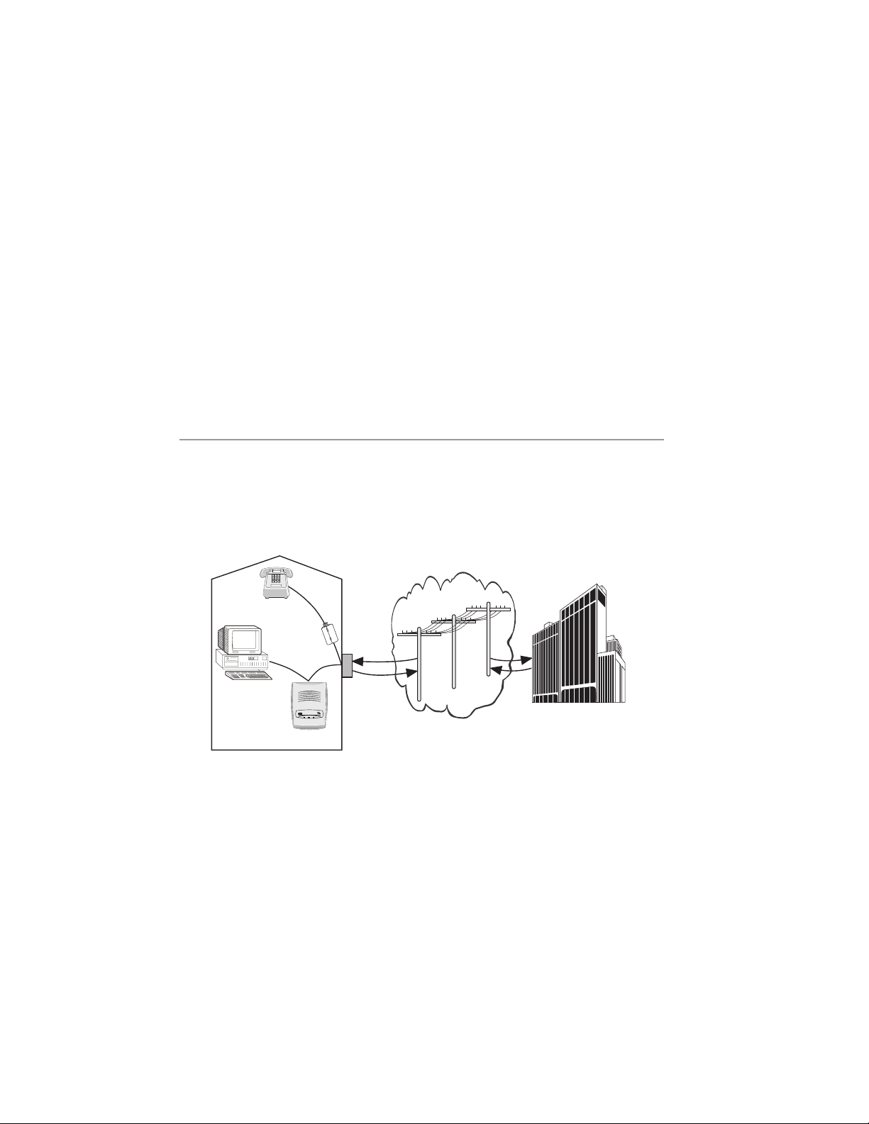
Congratulations on y our purchase of a Digital Subscriber Line
(DSL) m odem. The DSL modem is part of a system that
provides an integrated end-to-end solution for data
connectivity, mul timedia services, and high-speed Internet
access services using asymmetrical digital subscriber line
(ADSL) transmission over your current telephone wiring. With
ADSL technology, information can b e processeda t speedsup to
250 times faster than today’s analog modems.
1.1 ADSL Technology
The AD SL technology us es advanced digital modulation to
transmit at high speeds over standard telephone wiring. This
technology can download data at speeds up to 8 megabits per
secondanduploaddataatspeedsupto768kilobytesper
second.
Phone
LINE
PHONE
PC with
Ethernet
NIC
POWER MODEM DATA
DSL Modem
Local Telephone
Company
m1420.fh8_1
By using a DSL modem, Internet service providers and local
telephone companies can offer high-speed Internet access,
virtual private networks (VPNs), telecommuting, video on
demand, and other broadband services.
There are tw o methods of installingthe DSL modem service in
the home. Both methods are explained in the following
chapters. The first method, using microfilters, is explained in
Chapter 3. The microfilter removes high-frequency noise from
1
Page 8

your telephone sets and other telecommunication devices. The
second method requires a splitter and is explained in Chapter
4. If it is determined that a splitter is required, it will be
installed by your DSL service provider.
Whether microfilters or a splitter is installed, a DSL modem
allows telephone conversation and data downloads
simultaneously over the existing telephone line. The
microfiltersa nd splitter are c ompletely pa ssive. The telephone
service will work, ev en in instances of power outage. The D SL
modem encodes the data sent from the PC and sends it to a
corresponding DSL modem located at the local service
provider’s office.
1.2 Unpacking Instructions
Before unpacking, make a preliminary inspection of the
shipping box. Any evidence of damage should be noted and
reported immediately to a customer support center.
Note: The customer support information can be found in t he product
information packet provided by your DSL service prov ider. Keep the
shipping boxes and packing material for return.
It is recommended that you unpack the equipment on a clean,
flat surface.
1. Place the shipping box upright. Cut the sealing tape
and then open the flaps.
2. Take out the items in the box. Inspect the product for
damage and verify that all parts are included.
3. Report any damage or missing parts to the customer
support center.
2
Page 9

1.3 DSL Modem Package Contents
m0487.2
Part # FC9660CB23
m0494.3
Part # FC9660PS11
The DSL Modem package contains:
POWER MODEM DATA
Part # FC9660RA12
m0437.2
DSL Modem RJ-45 E thernet Crossover Cable
Part # FC9660CB26
m1225.fh8_2
RJ-11 to RJ-11 Line Cord Power Supply Convertor
LINE
PHONE
Microfilter
2-Outlet
Modular Adapter
operation)
m1226.fh8_2
Microfilter (splitterless
application)
m1224.fh8_1
Two-Outlet Modular Adapter (splitterless
Figure 1-1: DSL Modem Package Contents
3
Page 10

2 DSL Modem Description
2.1 DSL Front Panel
Figure 2-1 depicts the DSL modem LEDs.
SPEEDPORT
POWER MODEM DATA
Power LED
Modem LED
Data LED
Figure 2-1: DSL Modem LEDs
The following table describes the LEDs on the DSL mod em.
Modem Lights
On
POWER Indicates power is applied to the modem
MODEM Indicates a link with the phone company equipment
DATA Indicates the ADSL data rate is operating
4
Description
m1403.fh8_1
Page 11
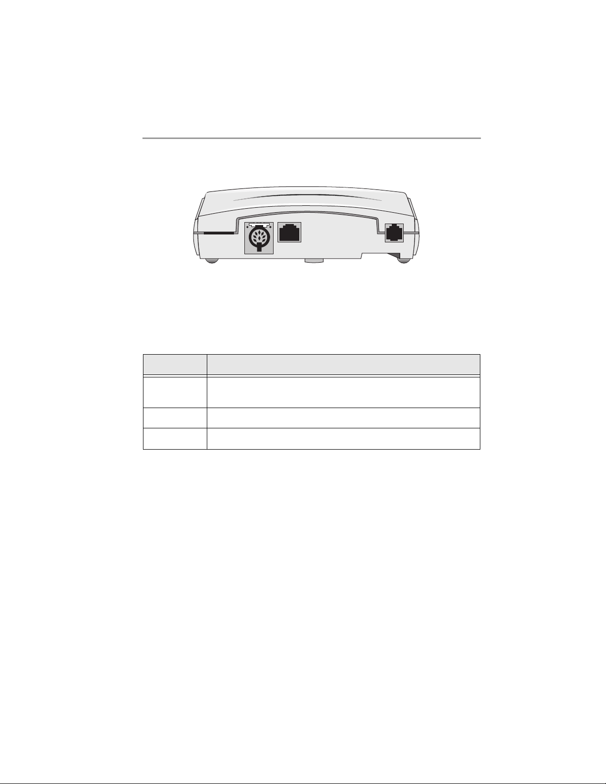
2.2 DSL Rear Panel
Figure 2-2 depicts the rear connections of the D SL modem.
DATA
DATA
LINE
LINE
m0436.2
Figure 2-2: DSL Rear Panel Connections
The following table lists and describes the functions of the
items located on the rear of the modem.
Connector Description
POWER Multipin connection for the power supply wall transformer
cable
DATA RJ-45 connection for the Ethernet cable ( crossover)
LINE RJ-11 cable connection to the wall plate
5
Page 12

2.3 DSL Bottom Panel
The DSL modem can be installed on a desktop, shelf, or
mounted on a wall. Wall mounting requires two wall anchors
(not included). The holes located on the bottom of the modem
are used to hang the unit on the wall anchors.
Figure 2-3 shows the bottom of the DSL modem.
Holes for
wall mounting
m0435.fh8_2
Figure 2-3: DSL Bottom Panel of Modem
6
Page 13

3 Installing the Splitterless DSL Modem
3.1 Overview
The procedures in this chapter apply to those c ustomers who
install their own microfilter-to-phone connections. If a DSL
technician is performing the wiring, proceed to Sec tion 5,
Powering the Modem.
Note: Do not install a mi c ro filter on the DSL modem line.
The splitterless installation requires the placement of a
microfilter on every telephone set, answering machine, or
telephone device (i.e., analog modem) in your home. However,
several phones and, or telephone devices may share the same
microfilter. Microfilters and modular adapters are included
with your modem package.
CAUTION:
Using more than five microfilters is not recommended and can impact
the quality of your telephone service.
Note: The following installation procedure and figures represent a
possible home scheme. No t all hom es will follow this convention. I t is
recommended that any DSL inside wiring be performed by a DSL
technician.
7
Page 14

3.2 Microfilter Installation Procedures
Installing microfilters should not require any new inside
wiring. Existing w ired RJ-11 telephone jacks are all that is
required to complete this installation. See Figure 3-1 for an
installation diagram.
LINE
PHONE
Microfilter
RJ-11
Phone
Jack
2-Outlet
Modular
Adapter
RJ-11 Line Cord
FC9660CB26
DATA
DATA
LINE
LINE
Line
POWER MODEM DATA
DSL Modem
FC9660RA12
Figure 3-1: Typical Splitterless Installation
1. Start in the location where you want to install your
DSL m odem. Look for the existing phone outlet (RJ-11
faceplate), and remove the existing RJ-11 cord from the
wall.
2. Connect the provided two-outlet modular adapter
device into the RJ-11 telephone jack.
3. Connectthe provided DSL modem RJ-11 line cord, part
number FC9660CB26, into one side of the two-outlet
modular adapter.
4. Connectthe other end into the RJ-11 L INE slot, located
on the back of DSL modem.
Telephone
m1227.fh8_4
5. Connect one of the provided microfilters into the
remaining empty two-outlet modular adapter slot.
8
Page 15

6. Connect the telephone RJ-11 cord connector into the
microfilter RJ-11 PHONE slot.
7. Connect all remaining telephone devices to a
microfilter. See Figure 3-2, 3-3, 3-4 for examples.
LINE
PHONE
Phone Jack Microfilter Telephone
Figure 3-2: Telephone Set Application
LINE
PHONE
RJ-11
Phone
Jack
Microfilter
Figure 3-3: Answering Machine Application
LINE
Phone Jack Microfilter
2-Outlet
Modular
Adapter
PHONE
1
2
4
3
5
7
6
8
9
Fax/Answering Machine
m1208.fh8_1
Telephone
TelephoneFax
m1210.fh8_2
m1209.fh8_1
Figure 3-4: Fax Application
9
Page 16

8. For an Ethernet connection, connect one end of the
Ethernet (crossover) cable, part number FC9660CB23,
to the RJ-45 slot titled DATA on the back of the DSL
modem and connect the other end of the Ethernet cable
to the network interface card in back of the computer.
See Figure 3-5 for examples.
Note: The term “straight,” when used to describe the cable
assemblies, is defined to mean that the transmit a nd receive pinouts rem ain the same entering and exiting the cable assembly.
The term “crossover” means that the transmit and receive pin-out
pair will be reversed or crossed over in the cable assemblies
2-Outlet
Modular Adapter
FC9660CB23
Crossover
supplied
DSL Modem
FC9660RA12
NIC Cable
Connection
LINE
PHONE
Microfilter
LINE
DATA
LINE
DATA
Data
Line
RJ-11 Line Cord
FC9660CB26
Telephone
Existing
RJ-11
Wallplate
m1230.fh8_5
10
Figure 3-5: E thernet Cable Connection
Page 17

3.3 Connecting Multiple PCs to an Ethernet Local Area
Network (LAN) using the Splitterless Application
Note: Connecting multiple PCs to the int ernet v ia a single DSL
modem may require multiple IP addresses. Call your local ISP
provider for det ails.
Figure 3-6 is an example of a residential, small office/home
office, or sm all business customer using ADSL to achieve highspeed access to the Internet. The DATA Ethernet connection
can interface a m ul tiport Ethernet hub. The hub allows
multiple PCs to share bandwidth to and from the DSL modem.
See section 3-2 for the microfilter installation procedure.
Note: The maximum distance for an Ethernet connection, us ing
category 3 or category 5 cable is 100 meters (325 feet).
2-Outlet
Modular
Adapter
Existing
LINE
Telephone
RJ-11
Wallplate
RJ-45 Ethernet
Cable (straight)
(not supplied)
Connection
Hub
DSL Modem
FC9660RA12
DATA
DATA
Data
NIC Cable
LINE
LINE
Line
Ethernet cable
(straight)
(not supplied)
RJ-11 Line Cord
FC9660CB26
PHONE
Microfilter
m1231.fh8_4
Figure 3-6: M ulti-User Eth ernet Internet Access
Note: Ethernet Hub and straight cables are not provided.
11
Page 18

4 Installing the DSL Modem with Splitter
4.1 Connecting the Inside Wire and Modem Cables
CAUTION:
Improper inside wiring c an cause ADSL serv ice interruption. Interior
home wire is the homeowner’s responsibility. Figure 4-1 represents a
standard wir ing scheme. Not all homes will follow this convention.
Standard telephone company inside wire c overage options will not cover
the cost to repair voice path problems that result from ho meowner wiring
attempts. These repairs may be billed to the homeowner as regular time
and ma terials repair charges. It is recommended that all ADSL inside
wiring be performed by a DSL service technician.
12
Inside Wire
DSL Splitter
Inside
1
Telephone
Network
Interface
To
Telephone
Company
*Asterisk denotes item included in the DSL Modem package.
RJ-11 Cable
DSL Modem*
FC9660RA12
Inside Wire Connections
Voice
Wire
4
FC9660CB26
3
RJ-11
Cable*
DATA 1
GR
GR
2
Data Wire
New Wall Plate
with RJ-11 Jack
LINE
LINE
Ethernet Cable*
FC9660CB23
(Crossover)
5
m1418.fh8_1
Figure 4-1: Connecting Inside Wire and Modem Cables
Page 19

Figure 4-2 shows an expanded view of the inside wiring of the
telephone network interface box.
1. On the outside of your house, locate and open the
telephone network interface box. (Your local DSL
service provider should have installed the DSL splitter)
Slide open the splitter latch door and locate the colored
screws. (Note the color of the wires that are connected
to the green and red screws.) See Figure 4-2 for an
illustration.
Telephone Network Interface Box
Red
Screw
Data
Voice
To Inside
Wall Plate
(Spare IW
or New IW)
m1379.fh8_1
DSL Splitter
TELEPHONE
COMPANY
ACCESS ONLY
DO NOT REMOVE
THIS COVER
LINE 1
LINE 2
LINE 3
LINE 4
LINE 5
LINE 6
Green
Screws
Red
Screw
To Inside Telephone
Wiring (connected
by DSL Service
Technician)
To Telephone Company Central Office
Twisted Pair Copper Cable
Figure 4-2: Telephone Network Interface Box- DSL Splitter
13
Page 20

2. Inside the residence, locate the telephone RJ-11 wall
jack that is nearest to your PC and remove it. Replace it
with a new dual RJ-11 wall plate and connect the same
colored wires that are attached to the green and red
screws on the DSL splitter data m odule to the green
and red pins on the RJ-11 wall jack. For example, if a
black wire is c onnected to the green screw in the data
side of the DSL splitter (see Figure 4-2 ), connect the
same black wire to the green pin of the new wall jack.
(If required, repeat this step for the voice wire.)
3. Connect the new RJ-11 cable, part number
FC9660CB26, by inserting the RJ-11 connector into the
RJ-11 data jack on the wall plate and the other end to
the LINE connector on the back of the DSL modem.
4. Connect your telephone set to the other telephone RJ11 voice jack on the wall plate.
5. For an Ethernet connection, connect one end of the
Ethernet (crossover) cable, part number FC9660CB23,
to the DATA connector on the back of the DSL modem
and c onnect the other end of the Ethernet cable to the
network interface card in the computer.
Note: The term “straight,” when used to describe the cable
assemblies, is defined to mean that the transmit a nd receive pinouts rem ain the same entering and exiting the cable assembly.
The term “crossover” means that the transmit and receive pin-out
pair will be reversed or crossed over in the cable assembly.
14
Page 21

4.2 Connecting Multiple PCs to an Ethernet Local Area
Network (LAN) using the Splitter Application
Note: Connecting multiple PCs to the Internet via a single DSL
modem may require multiple IP addresses. Call your ISP provider for
details.
Figure 4-3 is an example of a residential, small office/home
office, or sm all business customer using ADSL to achieve highspeed access to the Internet using multiple PCs. The DATA
connection can interface a multiport Ethernet hub. The hub
allows multiple PCs to share bandwidth to and from the DSL
modem. See Section 4-1 for the p rocedure to connect inside
wire and modem cables.
Note: The maximum di stance for an Ethernet connection, using
category 3 or category 5 cable, is 100 meters (325 feet).
Inside Wire
(CAT 3 not required)
DSL Splitter Inside
Telephone
Network
Interface
RJ-11
Cable
Multiple PC Application Using DSL Modem
Data Wire
Voice
Wire
GR
GR
DSL Modem*
FC9660RA12
New Wall Plate
with RJ-11 Jacks
RJ-11
Cable
FC9660CB26
.
To
Telephone
Company
*Asterisk denotes item included in the DSL Modem package.
Ethernet Cable
(Straight)
(not supplied)
LINE
DATA 1
LINE
Hub
Ethernet Cables
(Straight)
(not supplied)
Figure 4-3: Multi-User Speedport Internet Access
Note: Ethernet hub and straight cables are not p rovided.
m1419.fh8_1
15
Page 22

5 Powering the Modem
WARNING:
When installing the DSL modem power supply unit, be sure to fi r st insert
the power supply connector into the rear of the DS L modem before
plugging the unit into a powered 110V AC wall outlet.
Toa pply power to the DSL modem, p erform the following
steps:
1. Insert the power cable (DC connector) into the rear of
the DS L modem.
2. Plug the other end (AC male plug) of the power supply
cable into a 110V AC wall outlet.
Once the modem has pow er, it per forms several self-tests. The
POWER, MODEM, and DATA LED lights will be in a steady
state.
When the POWER light i s in a steady state and the MODEM
light blinks, a link is being established.
The m odem is operating at full capacity when the POWE R,
MODEM, and DATA lights remain in a steady state.
Note: Figure 5-1 is a DSL modem Turn-up Flow Chart. If the
POWER light is blinking, a failure has been detected during the selftest. Contac t the customer sup port center.
This completes the DSL modem installation and turn-up
procedure. If modem problems exist after reading and
following this procedure, please contact the customer support
center.
16
Page 23

DSL Modem Turn-up Flow Chart
POWER
POWER MODEM DATA
POWER MODEM DATA
POWER MODEM DATA
MODEM DATA
Modem is powered on. For a few seconds,
the modem is performing several self-tests.
Modem is idle. Modem is checking for presence
of the DSL local service provider . If the modem
stays in this state for more than 10 minutes, an
error has occurred. Contact the customer
support center.
Link between the modem and DSL local service
provider is established. Checking the software
version. If needed, modem will receive a
software upgrade from the DSL local service
provider. If the modem stays in this state for
more than 10 minutes, an error has occurred.
Contact the customer support center.
Receiving a software upgrade (if needed).
If the modem stays in this state for more than
10 minutes, an error has occurred. Contact
the customer support center.
POWER MODEM DATA
POWER MODEM DATA
Legend:
Software upgrade complete. Modem is
connected and communicating with the DSL
local service provider, but is operating at a
reduced speed. If the modem stays in this state
for more than 10 minutes, an error has occurred.
Contact the customer support center.
Modem is connected and communicating with
the DSL local service provider and is operating
at full speed.
OffOn Blinking
Figure 5-1: Turn-Up Flow Chart
m0495.fh8 4
17
Page 24

18
Page 25

19
 Loading...