

Page 1

Page 2

This page is intentionally left blank.
Page 3

This guide provides a variety of basic information about Web GUI for the ETERNUS DX80 S2/
DX90 S2 and the ETERNUS DX410 S2/DX440 S2 (hereinafter also referred to as "ETERNUS
DX Disk storage system" or "the device"). It should be referred to when setting up and
maintaining the ETERNUS DX Disk storage systems. This guide is specially written for the
ETERNUS DX Disk storage system Web GUI system administrators and operators.
Knowledge of UNIX or Windows® system management is required.
Structure of This Manual
This manual consists of the following 11 chapters and five appendixes.
● Chapter 1 Outline
This chapter describes the outlines, features, operation environment, user management
function, and operation screens for Web GUI.
Preface
Second Edition
June 2011
● Chapter 2 Startup and Shutdown
This chapter describes how to start, exit, log in and log out from Web GUI.
● Chapter 3 Initial Setup
This chapter describes the initial settings for the ETERNUS DX Disk storage systems.
● Chapter 4 Configuration Settings
This chapter describes the configuration settings for using Standard volumes and Thin Provisioning functions.
● Chapter 5 Volume Management
This chapter describes volume status and management.
● Chapter 6 RAID Group Management
This chapter describes RAID group status and management.
● Chapter 7 Thin Provisioning Pool Management
This chapter describes Thin Provisioning Pool status and management.
● Chapter 8 Advanced Copy Management
This chapter describes Advanced Copy status and management.
3
ETERNUS Web GUI User’s Guide
Copyright 2011 FUJITSU LIMITED P2X0-1090-02ENZ0
Page 4

Preface
● Chapter 9 Connectivity Management
This chapter describes connectivity settings between the host and the ETERNUS DX Disk
storage system.
● Chapter 10 Component Management
This chapter describes component status in the ETERNUS DX Disk storage system and
hardware maintenance.
● Chapter 11 System Management
This chapter describes system status and management.
The following items are provided in the Appendixes.
• User Roles and Policies
• Status List
• Naming Conventions of Volumes and Hosts
• Installing the Security Certificate
• RADIUS Authentication Notes
Latest Information
The information in this document is subject to change without notice for functionality expansion
and improvement of the ETERNUS DX Disk storage systems. The latest version of this
document and the latest information about the ETERNUS DX Disk storage systems is released
in the following web-site. Access the following address if needed.
URL: http://www.fujitsu.com/global/services/computing/storage/eternus/documentation/
Related Documents
Other documents for the ETERNUS DX80 S2/DX90 S2 and ETERNUS DX410 S2/DX440 S2 are
as follows:
• ETERNUS DX80 S2/DX90 S2 Disk storage system Overview
• ETERNUS DX80 S2/DX90 S2 User's Guide -Site Planning-
• ETERNUS DX80 S2/DX90 S2 User's Guide -Installation-
• ETERNUS DX80 S2/DX90 S2 User's Guide -Operation-
• ETERNUS DX410 S2/DX440 S2 Disk storage system Overview
• ETERNUS DX410 S2/DX440 S2 User's Guide -Site Planning-
• ETERNUS DX410 S2/DX440 S2 User's Guide -Installation & Operation-
• ETERNUS CLI User's Guide
-ETERNUS DX80 S2/DX90 S2, ETERNUS DX410 S2/DX440 S2-
• ETERNUS DX Disk storage systems User's Guide -Server Connection- (*1)
*1: Download the required manuals for your device environment (server OS and Fibre Channel card type,
etc.) from the specified web site. Refer to the Documentation CD provided with the ETERNUS DX
Disk storage system for URLs of the manual download site.
4
ETERNUS Web GUI User’s Guide
Copyright 2011 FUJITSU LIMITED P2X0-1090-02ENZ0
Page 5

Preface
Acknowledgments
• Microsoft, Windows, and Windows Server are either registered trademarks or trademarks of
Microsoft Corporation in the United States and other countries.
• UNIX is a registered trademark of The Open Group in the United States and other countries.
• Oracle and Java are registered trademarks of Oracle and/or its affiliates.
• AIX is a trademark of IBM Corp.
• Linux is a registered trademark or trademark of Linus Torvalds in the United States and other
countries.
• Red Hat, RPM, and all Red Hat-based trademarks and logos are trademarks or registered
trademarks of Red Hat, Inc. in the United States and other countries.
• HP-UX is a trademark of Hewlett-Packard in the U. S. and other countries.
• VMware, VMware logos, Virtual SMP, and VMotion are either registered trademarks or
trademarks of VMware, Inc. in the U. S. and/or other countries.
• Egenera BladeFrame and Egenera PAN Manager are trademarks or registered trademarks of
Egenera, Inc. in the USA and other countries.
• VERITAS Volume Manager is a trademark of Symantec Corp. and its affiliated companies.
• Other company names, product names, and service names are registered trademarks or
trademarks of their respective owners.
Naming Conventions
Product names
The following products will be represented throughout this manual by the following abbreviations.
• Microsoft® Windows® 2000 Server operating system and Microsoft® Windows® 2000
Advanced Server operating system are abbreviated as Windows® 2000.
• Microsoft® Windows Server® 2003, Standard Edition, and Microsoft® Windows Server®
2003, Enterprise Edition are abbreviated as Windows Server® 2003.
• Microsoft® Windows Server® 2008, Standard Edition, and Microsoft® Windows Server®
2008, Enterprise Edition are abbreviated as Windows Server® 2008.
• Windows® Server refers to both the Windows Server® 2003 and Windows Server® 2008.
• Windows® refers to all the Windows products listed here: Windows® 2000, Windows Server®
2003, and Windows Server® 2008.
• Oracle Solaris might be described as Solaris, Solaris Operating System, or Solaris OS.
5
ETERNUS Web GUI User’s Guide
Copyright 2011 FUJITSU LIMITED P2X0-1090-02ENZ0
Page 6

Preface
Units in this manual
Except as otherwise noted, the following units are used in this manual:
• Physical disk capacity and drive types assume that 1KB = 1,000 bytes, 1MB = 1,000KB, 1GB
= 1,000MB, and 1TB = 1,000GB (example: "600GB drive").
• Other logical capacities (for RAID Groups and volumes) assume that 1KB = 1,024 bytes, 1MB
= 1,024KB, 1GB = 1,024MB, and 1TB = 1,024GB.
Note that the screen shots in this manual were captured during development of the software and
the actual screens may be different.
Screen shot(s) reprinted with permission from Microsoft Corporation.
Copyright 2011 FUJITSU LIMITED
6
ETERNUS Web GUI User’s Guide
Copyright 2011 FUJITSU LIMITED P2X0-1090-02ENZ0
Page 7

Table of Contents
Chapter 1 Outline .....................................................................................12
1.1 Outline .............................................................................................................. 12
1.2 Features ........................................................................................................... 13
1.3 Operating Environment .................................................................................... 14
1.4 User Management ............................................................................................ 15
1.5 Screen Operations ........................................................................................... 16
1.5.1 Overview .................................................................................................................................... 16
1.5.2 Screen Structures ...................................................................................................................... 21
1.5.3 List Screen/Detailed Screen ...................................................................................................... 22
1.5.4 Basic Operation ......................................................................................................................... 23
Chapter 2 Startup and Shutdown ...........................................................25
2.1 Startup of GUI .................................................................................................. 25
2.2 Login ................................................................................................................ 27
2.3 Logout .............................................................................................................. 29
2.4 Exit ................................................................................................................... 30
Chapter 3 Initial Setup .............................................................................31
3.1 Initial Setup 1 ................................................................................................... 32
3.2 Initial Setup 2 ................................................................................................... 42
Chapter 4 Configuration Settings...........................................................54
4.1 Configuration Settings for Using Standard Volumes ........................................ 54
4.2 Configuration Settings for Using Thin Provisioning Functions ......................... 57
Chapter 5 Volume Management .............................................................58
5.1 Volume Status .................................................................................................. 58
5.1.1 Volume (Basic Information) ....................................................................................................... 58
5.1.2 Performance (Host I/O) ............................................................................................................. 60
5.1.3 Performance (Advanced Copy) ................................................................................................. 62
5.1.4 Reservation ............................................................................................................................... 63
5.1.5 Pinned Data ............................................................................................................................... 65
5.1.6 Bad Sector ................................................................................................................................. 65
5.1.7 Balancing Thin Provisioning Volume ......................................................................................... 67
5.1.8 Volume (Pinned Data) ............................................................................................................... 68
5.1.9 Volume (LUN Concatenation) .................................................................................................... 69
7
ETERNUS Web GUI User’s Guide
Copyright 2011 FUJITSU LIMITED P2X0-1090-02ENZ0
Page 8

Table of Contents
5.2 Functions in the Action Area for Volume .......................................................... 70
5.2.1 Create Volume ........................................................................................................................... 71
5.2.2 Delete Volume ........................................................................................................................... 77
5.2.3 Rename Volume ........................................................................................................................ 78
5.2.4 Format Volume .......................................................................................................................... 80
5.2.5 Expand Volume ......................................................................................................................... 81
5.2.6 Expand Thin Provisioning Volume ............................................................................................. 84
5.2.7 Start RAID Migration .................................................................................................................. 86
5.2.8 Stop RAID Migration .................................................................................................................. 89
5.2.9 Delete Snap Data Pool Volume ................................................................................................. 90
5.2.10 Force Delete Snap Data Pool Volume .......................................................................................91
5.2.11 Modify Threshold Thin Provisioning Volume ............................................................................. 92
5.2.12 Initialize Snap Data Volume ...................................................................................................... 93
5.2.13 Encrypt Volume ......................................................................................................................... 95
5.2.14 Forbid Advanced Copy .............................................................................................................. 96
5.2.15 Permit Advanced Copy .............................................................................................................. 97
5.2.16 Modify Cache Parameters ......................................................................................................... 97
5.2.17 Export Cache Parameters ....................................................................................................... 101
5.2.18 Export Performance Information .............................................................................................. 102
5.2.19 Release Reservation ............................................................................................................... 104
5.2.20 Start Balancing Thin Provisioning Volume .............................................................................. 105
5.2.21 Stop Balancing Thin Provisioning Volume ............................................................................... 107
Chapter 6 RAID Group Management....................................................109
6.1 RAID Group Status ........................................................................................ 109
6.1.1 RAID Group (Basic Information) .............................................................................................. 109
6.1.2 RAID Group (Tuning) ............................................................................................................... 111
6.1.3 RAID Group (ECO Mode) ........................................................................................................ 113
6.1.4 RAID Group (Volume Layout) .................................................................................................. 115
6.1.5 RAID Group (Disk) ................................................................................................................... 116
6.2 Functions in the Action Area for RAID Group ................................................ 117
6.2.1 Create RAID Group ................................................................................................................. 117
6.2.2 Delete RAID Group .................................................................................................................. 122
6.2.3 Rename RAID Group .............................................................................................................. 123
6.2.4 Change Controlling CM ........................................................................................................... 125
6.2.5 Expand RAID Group ................................................................................................................ 127
6.2.6 Modify RAID Group Parameters ..............................................................................................129
6.2.7 Assign ECO Mode Schedule ................................................................................................... 131
Chapter 7 Thin Provisioning Pool Management .................................135
7.1 Thin Provisioning Pool Status ........................................................................ 135
7.1.1 Thin Provisioning Pool (Basic Information) .............................................................................. 135
7.1.2 Thin Provisioning Pool (Threshold) ......................................................................................... 137
7.1.3 Thin Provisioning Pool (ECO Mode Schedule) ........................................................................ 139
7.1.4 Thin Provisioning Pool (License) ............................................................................................. 141
7.1.5 Thin Provisioning Pool Detail (Basic) ...................................................................................... 142
8
ETERNUS Web GUI User’s Guide
Copyright 2011 FUJITSU LIMITED P2X0-1090-02ENZ0
Page 9

Table of Contents
7.2 Functions in the Action Area for Thin Provisioning ........................................ 144
7.2.1 Create Thin Provisioning Pool ................................................................................................. 144
7.2.2 Delete Thin Provisioning Pool ................................................................................................. 153
7.2.3 Rename Thin Provisioning Pool .............................................................................................. 154
7.2.4 Expand Thin Provisioning Pool ................................................................................................ 156
7.2.5 Format Thin Provisioning Pool (All Area) ................................................................................ 162
7.2.6 Format Thin Provisioning Pool (Unformat Area) ...................................................................... 163
7.2.7 Modify Threshold Thin Provisioning Pool ................................................................................ 164
7.2.8 Assign ECO Mode Schedule ................................................................................................... 166
7.2.9 Register Thin Provisioning License ......................................................................................... 168
7.2.10 Delete Thin Provisioning License ............................................................................................ 170
Chapter 8 Advanced Copy Management .............................................171
8.1 Advanced Copy Status ................................................................................... 171
8.1.1 Advanced Copy (Basic Information) ........................................................................................ 172
8.1.2 Local Copy ............................................................................................................................... 173
8.1.3 Remote Copy ........................................................................................................................... 179
8.1.4 Setting ..................................................................................................................................... 183
8.1.5 Advanced Copy (Property) ...................................................................................................... 191
8.1.6 Advanced Copy (Extent information) ....................................................................................... 194
8.1.7 Copy Path (Details) ................................................................................................................. 195
8.2 Functions in the Action Area for Advanced Copy ........................................... 197
8.2.1 Start SnapOPC+ ...................................................................................................................... 199
8.2.2 Stop Session ........................................................................................................................... 202
8.2.3 Register Advanced Copy License ........................................................................................... 202
8.2.4 Delete Advanced Copy License ..............................................................................................205
8.2.5 Modify EC/OPC Priority ........................................................................................................... 205
8.2.6 Modify Copy Table Size ........................................................................................................... 207
8.2.7 Modify Copy Parameters ......................................................................................................... 215
8.2.8 Set Copy Path ......................................................................................................................... 217
8.2.9 Delete All Copy Path ............................................................................................................... 238
8.2.10 Export All Copy Path ............................................................................................................... 239
8.2.11 Export Storage Information ...................................................................................................... 240
8.2.12 Convert Copy Path .................................................................................................................. 242
8.2.13 Get Round Trip Time ............................................................................................................... 244
8.2.14 Modify REC Multiplicity ............................................................................................................ 246
8.2.15 Modify REC Buffer ................................................................................................................... 248
8.2.16 Assign REC Disk Buffer ........................................................................................................... 251
8.2.17 Create REC Disk Buffer ........................................................................................................... 255
8.2.18 Delete REC Disk Buffer ........................................................................................................... 258
8.2.19 Format REC Disk Buffer .......................................................................................................... 259
Chapter 9 Connectivity Management...................................................261
9.1 Connectivity Status ........................................................................................ 261
9.1.1 Connectivity (Basic Information) .............................................................................................. 262
9.1.2 Host Group .............................................................................................................................. 265
9
ETERNUS Web GUI User’s Guide
Copyright 2011 FUJITSU LIMITED P2X0-1090-02ENZ0
Page 10

Table of Contents
9.1.3 Port Group ............................................................................................................................... 270
9.1.4 LUN Group .............................................................................................................................. 277
9.1.5 Host Response ........................................................................................................................ 278
9.1.6 CA Reset Group ...................................................................................................................... 279
9.1.7 Host Group Detail .................................................................................................................... 280
9.1.8 LUN Group Detail .................................................................................................................... 281
9.2 Functions in the Action Area for Connectivity ................................................ 282
9.2.1 Host Affinity Management ....................................................................................................... 283
9.2.2 Host Group Management ........................................................................................................ 295
9.2.3 Port Group Management ......................................................................................................... 339
9.2.4 LUN Group Management ........................................................................................................ 375
9.2.5 Host Response Management ..................................................................................................381
9.2.6 Modify Reset Group ................................................................................................................. 393
Chapter 10 Component Management ....................................................395
10.1 Component Status ......................................................................................... 395
10.1.1 Component (Basic Information) ............................................................................................... 396
10.1.2 Controller Enclosure ................................................................................................................ 398
10.1.3 Drive Enclosure ....................................................................................................................... 408
10.1.4 Disks ........................................................................................................................................ 410
10.1.5 Controller Module Detail .......................................................................................................... 414
10.1.6 Channel Adapter Detail ........................................................................................................... 416
10.1.7 PSU/CPSU (CE) Detail ............................................................................................................ 419
10.1.8 Drive Enclosure Detail ............................................................................................................. 420
10.1.9 I/O Module Detail ..................................................................................................................... 424
10.1.10Power Supply Unit (DE) Detail ................................................................................................ 426
10.1.11Disks Detail .............................................................................................................................. 427
10.2 Functions in the Action Area for Component ................................................. 430
10.2.1 Add Drive Enclosure ................................................................................................................ 430
10.2.2 Turn on Locator Beacon/Turn off Locator Beacon .................................................................. 432
10.2.3 Add Channel Adapter Port ....................................................................................................... 434
10.2.4 Assign Global Hot Spare ......................................................................................................... 436
10.2.5 Release Global Hot Spare ....................................................................................................... 437
10.2.6 Assign Dedicated Hot Spare ................................................................................................... 438
10.2.7 Release Dedicated Hot Spare ................................................................................................. 440
10.2.8 Clear Disk Error Statistics (All Disks) ...................................................................................... 440
10.2.9 Clear Disk Error Statistics (Selected Disks) ............................................................................ 441
Chapter 11 System Management............................................................442
11.1 System Status ................................................................................................ 442
11.1.1 System (Basic Information) ..................................................................................................... 443
11.1.2 Network ................................................................................................................................... 444
11.1.3 Remote Support ...................................................................................................................... 446
11.1.4 User Settings ........................................................................................................................... 449
11.1.5 ECO Mode ............................................................................................................................... 449
10
ETERNUS Web GUI User’s Guide
Copyright 2011 FUJITSU LIMITED P2X0-1090-02ENZ0
Page 11

Table of Contents
11.1.6 Event/Dump ............................................................................................................................. 450
11.1.7 Utility ........................................................................................................................................ 451
11.1.8 System Settings ....................................................................................................................... 451
11.1.9 ECO Mode Schedule Detail ..................................................................................................... 452
11.2 Functions in the Action Area for System ........................................................ 453
11.2.1 Change User Password ........................................................................................................... 455
11.2.2 Set SSH Public Key ................................................................................................................. 456
11.2.3 Network Management ............................................................................................................. 458
11.2.4 Remote Support Management ................................................................................................501
11.2.5 User Settings ........................................................................................................................... 523
11.2.6 ECO Mode Management ......................................................................................................... 539
11.2.7 Event/Dump Management ....................................................................................................... 550
11.2.8 Utility Management .................................................................................................................. 570
11.2.9 System Management ............................................................................................................... 575
Appendix A User Roles and Policies.......................................................592
A.1 Roles ............................................................................................................... 592
A.2 Availability of Functions for each Policy .......................................................... 593
Appendix B Status List .............................................................................612
B.1 Device General Status .................................................................................... 612
B.2 Volume Status................................................................................................. 613
B.3 RAID Group Status ......................................................................................... 614
B.4 Thin Provisioning Pool Status ......................................................................... 615
B.5 Component Status .......................................................................................... 615
B.5.1 Drive Status ............................................................................................................................. 616
Appendix C Naming Conventions of Volumes and Hosts.....................617
C.1 Naming Convention of Volumes...................................................................... 617
C.2 Naming Convention of Hosts .......................................................................... 618
C.2.1 For FC Hosts ........................................................................................................................... 618
C.2.2 For iSCSI Hosts....................................................................................................................... 619
C.2.3 For SAS Hosts......................................................................................................................... 620
Appendix D Installing the Security Certificate .......................................622
D.1 For Internet Explorer ....................................................................................... 622
D.2 For Firefox....................................................................................................... 627
Appendix E Using RADIUS Authentication ............................................630
E.1 Using RADIUS Authentication to
Access the ETERNUS DX Disk Storage System............................................ 630
E.2 Notes when Using RADIUS Authentication for GUI ........................................ 631
E.3 Setting Up the RADIUS Server ....................................................................... 631
11
ETERNUS Web GUI User’s Guide
Copyright 2011 FUJITSU LIMITED P2X0-1090-02ENZ0
Page 12

Chapter 1 Outline
LAN
PC
Web Browser
Management Server
Mail Server Program
(*1)
*1: Connect the operation server and the ETERNUS DX Disk storage system
Operating via
Web GUI
ETERNUS DX80 S2/ DX90 S2
Server
web browser
with one of the following cables:
Operation
Fibre Channel (FC) cable
iSCSI cable
SAS cable (available only for the ETERNUS DX80S2/DX90 S2)
ETERNUS DX410 S2/DX440 S2
This chapter describes the outlines, features, operating environment, user management function,
and operation screens for ETERNUS DX Disk storage system Web GUI (hereinafter referred to
as "GUI").
GUI is installed in controllers of the ETERNUS DX Disk storage systems, and used for perform-
ing settings and maintenance via web browser.
1.1 Outline
Use GUI to set the operating environment and check status for the ETERNUS DX Disk storage
system.
GUI can be operated from a web browser by connecting the PC via a LAN connection.
Refer to "Chapter 2 Startup and Shutdown" (page 25)
ETERNUS Web GUI User’s Guide
for details of GUI start up.
12
Copyright 2011 FUJITSU LIMITED P2X0-1090-02ENZ0
Page 13

Chapter 1 Outline
1.2 Features
1.2 Features
The features for GUI are as follows:
● Initial settings by the wizard
● Status Display
● Checking the extent of a failure
● Easy operation
The wizard provides instructions for the basic settings that are required to run the ETERNUS
DX Disk storage system.
This function displays the device installation image.
If a drive failure occurs, host port, LUN group, volume, RAID group, and installation location
can be referenced to determine the extent of the failure.
If a hardware failure is detected, the system administrator can receive a mail containing
detected failure information.
13
ETERNUS Web GUI User’s Guide
Copyright 2011 FUJITSU LIMITED P2X0-1090-02ENZ0
Page 14

Chapter 1 Outline
1.3 Operating Environment
1.3 Operating Environment
The following PC environment is required to use GUI.
Confirmed operating environment Ver sion
Web browser Microsoft® Internet Explorer 7.0, 8.0
Mozilla Firefox™ 3.6.X
Image resolution
• 1024 x 768 or more
• 24-bit color or more is recommended
• Note the following:
- Set "Do not use proxy server" as the proxy setting
- Set page acquisition to not use the cache
When using Internet Explorer 7.0, select [Every time you start Internet Explorer].
- Enable the Java Script setting
- When Auto Reading of pages is available, enable the setting
• Furthermore, when using ETERNUSmgr with Microsoft® Internet
Explorer 7.0, note the following:
- Enable [Automatic prompting for file downloads] and [Allow websites
to open windows without address or status bars] under the Internet
Options Security tab.
- Disable the [Show friendly HTTP error messages] under the Internet
Options Advanced tab.
• Furthermore, when using ETERNUSmgr with Microsoft® Internet
Explorer 8.0, note the following:
- Enable [Automatic prompting for file downloads] and [Allow websites
to open windows without address or status bars] under the Internet
Options Security tab.
- Disable the SmartScreen Filter in the [Tools] menu, or disable the
SmartScreen Filter by clicking the [Safety] button, or delete the
default gateway settings of the PC.
• If the PC and the ETERNUS DX Disk storage system belong to a
different network and the transfer rate setting for each network does not
match, the retransmission of packets occur more frequently and the
operation screen for Web GUI may take more time to display.
By setting the same transfer rate for each network, the retransmission of
packets can be reduced. Note the following points when setting the
transfer rate:
- Set the same transfer rate for each network
- When the transfer rate for the ETERNUS DX Disk storage system is
not "Auto-negotiation", the same transfer rate must also be set for
the network switches
–
14
ETERNUS Web GUI User’s Guide
Copyright 2011 FUJITSU LIMITED P2X0-1090-02ENZ0
Page 15

Chapter 1 Outline
1.4 User Management
1.4 User Management
Appropriate user management is important to ensure that security is maintained within the sys-
tem.
The user management function applies roles with multiple policies when user accounts are cre-
ated to specify the functions that are allowed for each user. For normal operation of the ETER-
NUS DX Disk storage system, apply the "Admin" default role for the system administrator and
apply the "Maintainer" default role for the maintenance engineer.
Operation mistakes and maintenance worker hours can be reduced and device security can be
improved by placing the authorized functions of system administrators in units of usage and by
only giving the minimum necessary policies to system administrators.
Refer to "Appendix A User Roles and Policies" (page 592) for details about
user roles and policies.
15
ETERNUS Web GUI User’s Guide
Copyright 2011 FUJITSU LIMITED P2X0-1090-02ENZ0
Page 16

Chapter 1 Outline
1.5 Screen Operations
1.5 Screen Operations
This section provides a description about GUI screen operations.
Click the [Help] link for a detailed explanation of the functions used during operation. An
explanation (help) screen of the function is displayed.
1.5.1 Overview
• The [Initial Setup] screen is displayed for the first login after installation
of the ETERNUS DX Disk storage system is complete.
• Be sure to log out after all necessary operations are completed.
• If the operation screen is not updated when accessing the GUI, close
the web browser, and log in again.
Overview screen appears immediately after logging in to the Web GUI. The status of the
ETERNUS DX Disk storage system and the usage of RAID groups, Thin Provisioning Pools
(TPP), and Snap Data Pools (SDP) can be checked in this screen.
• TPP usage is displayed only when the Thin Provisioning license is
registered.
• SDP usage is displayed only when the Advanced Copy license is
registered.
Clicking the [Refresh] link to display the latest information.
16
ETERNUS Web GUI User’s Guide
Copyright 2011 FUJITSU LIMITED P2X0-1090-02ENZ0
Page 17
Chapter 1 Outline
1.5 Screen Operations
■ System Message
A system message is displayed.
■ Hardware Components
The number of components for each status is displayed.
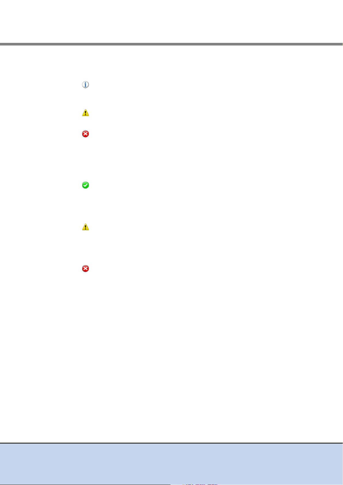
• Message
When any information from the ETERNUS DX Disk storage system exists, an information
message is displayed.
• Message
When an event causes warning status, a warning message is displayed.
• Message
When an event causes error status, an error message is displayed.
• Normal
- Modules
The number of components in normal status (*1) is displayed.
- Disks
The number of drives in normal status is displayed.
• Warning
- Modules
The number of components in warning status (*1) is displayed.
- Disks
The number of drives in warning status is displayed.
• Error
- Modules
The number of components in error status (*1) is displayed.
- Disks
The number of drives in error status is displayed.
*1: The number of components that can be maintained. The number of components does not include the
number of drives.
■ System information
The information of the ETERNUS DX Disk storage system is displayed.
• Storage System Name
The name for the ETERNUS DX Disk storage system is displayed.
Clicking this item displays the [Storage] screen in the [Component] navigation.
• Model Name
The model name of the ETERNUS DX Disk storage system is displayed.
• Serial No.
The serial number of the ETERNUS DX Disk storage system is displayed.
17
ETERNUS Web GUI User’s Guide
Copyright 2011 FUJITSU LIMITED P2X0-1090-02ENZ0
Page 18

Chapter 1 Outline
1.5 Screen Operations
• Firmware Version
The current controller firmware version is displayed.
- VxxLyy-zzzz (Vxx: Version, Lyy: Level, zzzz: Release number)
• Cache Mode
The current status and the factor of the cache are displayed. The normal status is "Write Back
Mode".
- Write Back Mode
When a Write request is issued from the host, "Write Complete" is displayed after writing to
the cache area is complete.
- Write Through Mode
When a Write request is issued from the host, "Write Complete" is displayed after writing to
the cache area and the drives is complete.
In the Write Through Mode, "Write Through (factors)" is displayed. When there are
multiple factors, all the factors are displayed.
The factors of the Write Through Mode are described below:
• Write Through (Pinned Data)
A large amount of pinned data (*1) occurred in the ETERNUS DX Disk storage system.
• Write Through (Battery)
The battery charge level is low.
• Write Through (Maintenance)
The following maintenance operation is currently being used:
- Switch Controller Firmware
- Change Controlling CM
- Add Controller Module
*1: "Pinned data" is the data left in the cache memory due to unsuccessful write-back to the
volume from the cache memory.
• Connecting Module
The Controller Module (CM) to which the GUI is connected is displayed.
• Status
The status of the ETERNUS DX Disk storage system is displayed.
- Normal
- Maintenance
- Warning
- Error
- Not Ready (*)
*: Not Ready number is displayed.
■ RAID Groups
The usage of RAID groups is displayed.
• Pie chart
The pie chart indicates the total used capacity and the total free capacity in the RAID groups.
Blue: Total used capacity
Gray: Total free capacity
18
ETERNUS Web GUI User’s Guide
Copyright 2011 FUJITSU LIMITED P2X0-1090-02ENZ0
Page 19

Chapter 1 Outline
1.5 Screen Operations
• RAID Group Count
The number of RAID groups registered in the ETERNUS DX Disk storage system is
displayed.
"RAID Group Count" includes the number of RAID groups that configure TPPs and the
number of RAID groups that are registered as REC Disk Buffers.
• Volume Count
The number of volumes registered in the ETERNUS DX Disk storage system is displayed.
"Volume Count" displays the number of "Standard" type volumes.
• Total Used Capacity
The total used capacity of the RAID groups [MB/GB/TB] is displayed. The "Total Used Capacity" is the total capacity of all of the RAID groups that are used. An example of this capacity is
space that is used for volumes in the RAID groups. This value does not include the capacity of
RAID groups that configure TPPs and the capacity of RAID groups that are registered as REC
Disk Buffers.
• Total Free Capacity
The total free capacity of the RAID groups [MB/GB/TB] is displayed. The "Total Free Capacity" is a total of unused capacities in the RAID groups. This value does not include the
capacity of RAID groups that configure TPPs and the capacity of RAID groups that are
registered as REC Disk Buffers.
• Total Capacity
The total capacity of the RAID groups [MB/GB/TB] is displayed. The "Total Capacity" is the
total capacity of all the RAID groups in the ETERNUS DX Disk storage system. This value
does not include the capacity of RAID groups that configure TPPs and the capacity of RAID
groups that are registered as REC Disk Buffers.
Total Free Capacity = Total Capacity - Total Used Capacity
■ Thin Provisioning Pool
The usage of TPP is displayed.
• Pie chart
The pie chart indicates the total used physical capacity and the total free physical capacity in
the TPPs.
Blue: Total used physical capacity
Gray: Total free physical capacity
• Thin Provisioning Pool Count
The number of TPPs registered in the ETERNUS DX Disk storage system is displayed.
• Volume Count
The number of volumes registered in the ETERNUS DX Disk storage system is displayed.
This value displays the number of "TPV" type volumes.
• Total Used Physical Capacity
The total used physical capacity of the TPPs [MB/GB/TB] is displayed. The "Total Used Physical Capacity" is the total physical capacity of all the TPPs that are used for volumes.
• Total Free Physical Capacity
The total free physical capacity of the TPPs [MB/GB/TB] is displayed. The "Total Free Physical Capacity" is the total unused physical capacity of all the TPPs.
19
ETERNUS Web GUI User’s Guide
Copyright 2011 FUJITSU LIMITED P2X0-1090-02ENZ0
Page 20

Chapter 1 Outline
1.5 Screen Operations
■ Snap Data Pool
The usage of SDP is displayed.
• Total Physical Capacity
The total physical capacity of the TPPs [MB/GB/TB] is displayed. The "Total Physical Capacity" is the total physical capacity of all the TPPs in the ETERNUS DX Disk storage system.
Total Free Physical Capacity = Total Physical Capacity - Total Used Physical Capacity
• Pie chart
The pie chart indicates the total used capacity and the total free capacity in the SDP.
Blue: Total used capacity
Gray: Total free capacity
• Snap Data Pool Count
The number of SDPs that are registered in the ETERNUS DX Disk storage system is
displayed.
• Total Used Capacity
The total used capacity of the SDP [MB/GB/TB] is displayed. The "Total Used Capacity" is the
total capacity of all the SDPs that are used for volumes.
• Total Free Capacity
The total free capacity of the SDP [MB/GB/TB] is displayed. The "Total Free Capacity" is the
total unused capacity of all the SDPs.
• Total Capacity
The total capacity of the SDP [MB/GB/TB] is displayed. The "Total Capacity" is the total
capacity of all the SDPs in the ETERNUS DX Disk storage system.
Total Free Capacity = Total Capacity - Total Used Capacity
20
ETERNUS Web GUI User’s Guide
Copyright 2011 FUJITSU LIMITED P2X0-1090-02ENZ0
Page 21

Chapter 1 Outline
Category
Main
Action
Header
Navigation
Bread crumb list
1.5 Screen Operations
1.5.2 Screen Structures
This section describes screen layouts for functions other than Overview screen.
■ Header
User ID, [Logout] link, general status, storage system name, model, date, [Refresh] link, and
[Help] link are displayed in the header. When maintenance is being performed for the ETERNUS
DX Disk storage system, the "Maintenance Mode" icon is displayed.
The header is always displayed.
• General status of the ETERNUS DX Disk storage system
Status of each component in the ETERNUS DX Disk storage system is monitored
periodically, and the result is displayed as a general status icon with character strings. Refer
to "B.1 Device General Status" (page 612)
for details about the general status.
■ Navigation
Overview, Volume, RAID Group, Thin Provisioning, Advanced Copy, Connectivity, Component,
and System tabs are displayed.
Click the tab for the function that is to be used to display a list screen for that function.
The navigation is always be displayed.
■ Bread crumb list
Bread crumb indicates the location of the current screen on the GUI.
Clicking the link displays the list screen of the target item.
21
ETERNUS Web GUI User’s Guide
Copyright 2011 FUJITSU LIMITED P2X0-1090-02ENZ0
Page 22
Chapter 1 Outline
Links to detailed screen
1.5 Screen Operations
■ Category
The subordinate items are displayed for an item that is clicked in the navigation. The category
directory is used for switching the contents that are displayed in the Main screen. Click the item
for the function that is to be used.
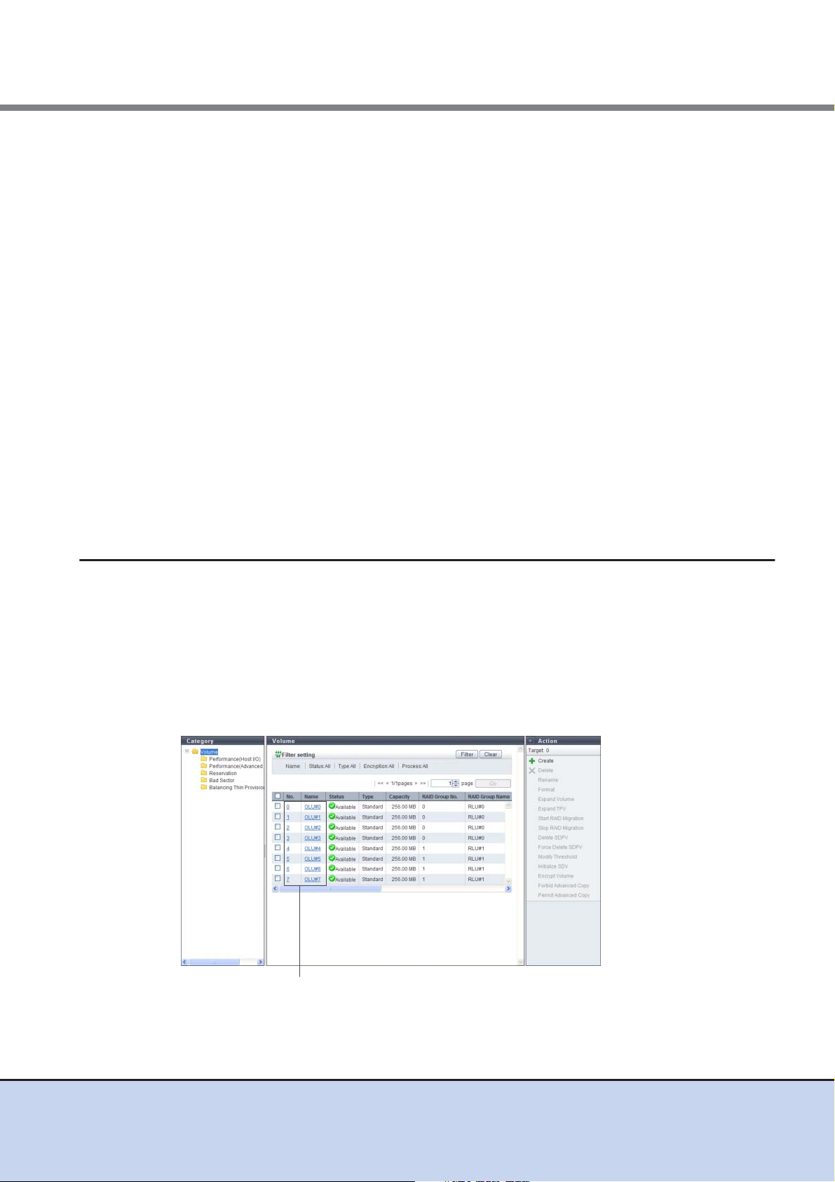
■ Main
A list of items is displayed for an item that is clicked on the navigation or in the category.
The filter setting area may also be displayed for some lists.
■ Action
Only the available functions for the selected items from the navigation or in the category are dis-
played. Click the function that is to be used to display the wizard screen.
Clicking the [>>] button switches the display of action area.
• Filter setting
Filter setting is a function used to display a list of only the items meeting all the specified
conditions. The conditions that are available depend on the function. No filtering is set by
default.
1.5.3 List Screen/Detailed Screen
There are two types of main screens; a list screen and a detailed screen.
The header, bread crumb list, and navigation areas are not included in the screen shots in this
section.
■ List screen
A list of the items that were clicked on the navigation or in the category is displayed. For items
with detailed information, links to the detailed screens are displayed.
22
ETERNUS Web GUI User’s Guide
Copyright 2011 FUJITSU LIMITED P2X0-1090-02ENZ0
Page 23

Chapter 1 Outline
Tabs to change detailed screens
Filter setting
Sorting criteria
Select All checkbox
1.5 Screen Operations
■ Detailed screen
Click the link for each item in the list screen to display a detailed screen. Click the tabs that are
displayed to switch the display.
For some items, the same information may be displayed for the list screen
and the detailed screen. From Chapter 5 onward, only the information for
items in the detailed screen that is different from the list screen is
described.
1.5.4 Basic Operation
Select the desired item and execute the selected operation.
23
ETERNUS Web GUI User’s Guide
Copyright 2011 FUJITSU LIMITED P2X0-1090-02ENZ0
Page 24
Chapter 1 Outline
1.5 Screen Operations
■ Selecting an operation
When an item in the navigation or category is clicked, a list items for the selected item is dis-
played. Select the checkbox or checkboxes of the listed items for the desired operation. Note
that some operations, such as creating new volumes, do not require the item to be selected.
The following operations are available in the list screen:
• Filter setting
Filter setting is a function used to display a list of only the items that meet all the specified
conditions. The settings that can be specified vary depending on the function that is selected.
No filtering is set by default.
• Sort
Sorting is a function that rearranges the order of the displayed items in ascending order (A - Z
or 0 - 9), in descending order (Z - A or 9 - 0), or in a specific order. Clicking the sorting criteria
changes the order. The item that is furthest to the left is displayed in ascending order by
default.
• Select all checkbox
The "Select All" checkbox is the first item in the left of the item field. Click this checkbox to
select all of the checkboxes that are listed. This checkbox is left clear by default.
■ Executing an operation
Select the desired operation item from the navigation or category, and then select the function
that is to be executed in the Action field.
Only the available functions for the displayed item are displayed in the Action field.
Some functions in the Action field require one target item from the list to be selected, some func-
tions require multiple target items to be selected, and other functions can be performed without
selecting any items.
The header, bread crumb list, and navigation areas are not included in the
screen shots in the following chapters and sections.
24
ETERNUS Web GUI User’s Guide
Copyright 2011 FUJITSU LIMITED P2X0-1090-02ENZ0
Page 25

Chapter 2 Startup and Shutdown
Procedure
This chapter describes how to start, exit, log in, and log out from GUI.
2.1 Startup of GUI
Startup the login screen for GUI.
Connect the PC and the ETERNUS DX Disk storage system using a LAN cable, and display the
login screen via the web browser.
The procedure to start up the login screen for GUI is as follows:
1 Directly connect the PC and MNT port of the ETERNUS DX Disk storage system
via LAN cable.
2 Set the IP address and subnet mask for the PC to match the ETERNUS DX Disk
storage system network settings.
3 Enter "http://IP address of the device/" to the address bar in the web browser
(Default IP address is "192.168.1.1").
→ The login screen for GUI is displayed. Refer to "2.2 Login" (page 27) for detailed
procedure to login.
25
ETERNUS Web GUI User’s Guide
Copyright 2011 FUJITSU LIMITED P2X0-1090-02ENZ0
Page 26

Chapter 2 Startup and Shutdown
End of procedure
2.1 Startup of GUI
• When using SSL (https), the "SSL Server Certificate" or the "Self-
signed SSL Certificate" must be registered in the ETERNUS DX
Disk storage system in advance. To obtain the "SSL Server
Certificate", send the CSR (downloaded using the procedure in
"11.2.3.16 Create Key/CSR" (page 492)
authority. Register the obtained "SSL Server Certificate" by using
the procedure in "11.2.3.17 Register SSL Certificate" (page 497)
To obtain the "Self-signed SSL Certificate", use the procedure in
"11.2.3.15 Create Self-signed SSL Certificate" (page 490)
register the created "Self-signed SSL Certificate" in the
ETERNUS DX Disk storage system. Refer to "Appendix D
Installing the Security Certificate" (page 622) for details on how to
register the "Self-signed SSL Certificate".
• If Firefox 3.6.x is used for connecting to the ETERNUS DX Disk
storage system via "https", a communication error may occur.
This error can be avoided by connecting via "http" or by using
"Internet Explorer".
to the certification
and
.
• Refer to "11.2.3.1 Setup Network Environment" (page 458) for
procedure to set the IP address of the MNT port.
• The default number of port that is used for http connection is "80".
26
ETERNUS Web GUI User’s Guide
Copyright 2011 FUJITSU LIMITED P2X0-1090-02ENZ0
Page 27

Chapter 2 Startup and Shutdown
Procedure
2.2 Login
2.2 Login
Log in to GUI to start the operation. The GUI operation screen appears.
The menu that is displayed depends on the role that is applied for the user account.
The procedure for logging in is as follows:
1 Click the [Option] button in the login screen, and select the language (English or
Japanese).
If a login is attempted while 16 users are already logged in to the GUI, an
error screen appears. When this occurs, note the error message and try
logging in again after completing the required operation.
2 Enter the User ID and Password, and click the [Login] button.
The User ID and the Password vary depending on which account is being used to log in.
• User ID
root
• Password
root (Default)
• Refer to "11.2.5 User Settings" (page 523) for user accounts.
• If the input error occurs, enter the User ID and Password again to
log on to the ETERNUS DX Disk storage system.
→ The operation screen appears.
27
ETERNUS Web GUI User’s Guide
Copyright 2011 FUJITSU LIMITED P2X0-1090-02ENZ0
Page 28

Chapter 2 Startup and Shutdown
End of procedure
2.2 Login
Up to 16 users can be logged in concurrently from the GUI (the number of users that are logged from CLI is not included). Logging in 17
or more users is not allowed.
Also note that when another user is already logged in and performing
one of the following operations, a warning message appears and
some functions cannot be used. Confirm the current GUI usage state
and start operation.
• When applying controller firmware
• When applying disk firmware
• During the RAID group diagnosis
• During the disk diagnosis
28
ETERNUS Web GUI User’s Guide
Copyright 2011 FUJITSU LIMITED P2X0-1090-02ENZ0
Page 29

Chapter 2 Startup and Shutdown
Procedure
End of procedure
2.3 Logout
2.3 Logout
Log out from GUI to finish the operation.
The procedure for logging out is as follows:
A logout is performed automatically under the following conditions:
• When a different user executes a forcible logout (*1)
• When the ETERNUS DX Disk storage system is turned off
• When no operation is performed for 60 minutes or longer after logging in
*1: When the user name is the same as a user who is already logged in, the
user who was previously logged in is forcibly logged out.
1 Click the [Logout] link on the top right of the screen.
→ A confirmation screen appears.
2 Click the [OK] button.
→ This completes the logging out process.
The login screen appears.
29
ETERNUS Web GUI User’s Guide
Copyright 2011 FUJITSU LIMITED P2X0-1090-02ENZ0
Page 30

Chapter 2 Startup and Shutdown
Procedure
End of procedure
2.4 Exit
2.4 Exit
Exit from GUI.
The procedure to exit is as follows:
1 Click the [Close] button for the web browser.
→ Exit from GUI.
Make sure to perform "2.3 Logout" (page 29) operation before exiting GUI.
If exiting GUI without logging out, the login status is not released.
The login screen does not appear.
30
ETERNUS Web GUI User’s Guide
Copyright 2011 FUJITSU LIMITED P2X0-1090-02ENZ0
Page 31

Chapter 3 Initial Setup
This chapter describes the Initial Setup function for the ETERNUS DX Disk storage system.
This function performs the required initial settings that must be set before operating the
ETERNUS DX Disk storage system on a series of wizard screens.
Initial Setup is divided into "Initial Setup 1" and "Initial Setup 2".
• Initial Setup 1
Performs the minimum settings required before using the ETERNUS DX Disk storage system.
• Initial Setup 2
Makes the reporting settings for when an error occurs in the ETERNUS DX Disk storage
system. The settings can be omitted if the reporting function will not be used.
If the browser is shut down during execution of Initial Setup, other functions
will no longer be available. If this case, forcibly log in using the same user
name, and perform Initial Setup 1 again from the beginning. However, if you
have already reached Initial Setup 2, the wizard is executed from the
beginning of Initial Setup 2.
The settings made in the Initial Setup can be changed individually later.
31
ETERNUS Web GUI User’s Guide
Copyright 2011 FUJITSU LIMITED P2X0-1090-02ENZ0
Page 32

Chapter 3 Initial Setup
3.1 Initial Setup 1
3.1 Initial Setup 1
The flow of wizard operations in Initial Setup 1 is shown below.
(1) Set Storage Name
Register the name, administrator, and installation site of the ETERNUS DX Disk storage
system. Refer to "11.2.9.1 Modify Storage Name" (page 576)
(2) Set Date and Time
Set the date/time and time zone (device location) of the internal clock in the ETERNUS DX
Disk storage system. Refer to "11.2.9.2 Modify Date and Time" (page 577)
(3) Change Password
Change the password for the default account that is currently logged in before starting to use
the ETERNUS DX Disk storage system. Refer to "11.2.1 Change User Password" (page 455)
for details.
for details.
for details.
(4) Register Thin Provisioning License
If using the Thin Provisioning function, register the license here. Refer to "7.2.9 Register Thin
Provisioning License" (page 168) for details.
(5) Register Copy License
If using the Advanced Copy function, register the license here. Refer to "8.2.3 Register
Advanced Copy License" (page 202) for details.
(6) Register SED Authentication Key
Register the SED Authentication Key to enable encryption of the SEDs. Refer to "11.2.9.7
Register SED Authentication Key" (page 588) for details.
(7) Set Network Environment
Set the environment for the ETERNUS DX Disk storage system to communicate on the
network such as IP address and subnet mask. Refer to "11.2.3.1 Setup Network
Environment" (page 458) for details.
Log out when the settings are complete. Log in again, and then proceed to "3.2 Initial Setup 2"
(page 42).
If SED has been installed before registering the SED authentication key, reboot the ETERNUS
DX Disk storage system before logging in again.
32
ETERNUS Web GUI User’s Guide
Copyright 2011 FUJITSU LIMITED P2X0-1090-02ENZ0
Page 33

Chapter 3 Initial Setup
Procedure
3.1 Initial Setup 1
The procedure to perform Initial Setup 1 is as follows:
1 Click [Start Initial Setup] in [Action].
The [Start Initial Setup] screen is displayed after logging in for the
first time.
2 Click the [Next] button.
→ Initial Setup starts.
33
ETERNUS Web GUI User’s Guide
Copyright 2011 FUJITSU LIMITED P2X0-1090-02ENZ0
Page 34

Chapter 3 Initial Setup
3.1 Initial Setup 1
3 Proceed to [Set Storage System Name].
3-1 Specify the following items, and click the [Next] button.
- Name
- Installation Location
- Administrator
- Description
→ A confirmation screen appears.
• If logging in for the first time, be sure to set the name of the
ETERNUS DX Disk storage system.
• If not logging in for the first time, click the [Skip] button to
proceed to the next screen without setting.
3-2 Click the [OK] button.
→ Setting of the storage system name starts.
3-3 Click the [Done] button.
34
ETERNUS Web GUI User’s Guide
Copyright 2011 FUJITSU LIMITED P2X0-1090-02ENZ0
Page 35

Chapter 3 Initial Setup
3.1 Initial Setup 1
4 Proceed to [Set Date and Time].
4-1 Specify the following items, and click the [Next] button.
- Date/Time Information
- Time Zone
- Daylight Saving Time
- NTP Service
→ A confirmation screen appears.
Click the [Skip] button to proceed to the next screen without
setting.
4-2 Click the [OK] button.
→ Setting of the Date/time starts.
4-3 Click the [Done] button.
35
ETERNUS Web GUI User’s Guide
Copyright 2011 FUJITSU LIMITED P2X0-1090-02ENZ0
Page 36

Chapter 3 Initial Setup
3.1 Initial Setup 1
5 Proceed to [Change Password].
5-1 Specify the following items, and click the [Next] button.
- Old Password
- New Password
- Confirm New Password
Click the [Skip] button to proceed to the next screen without
setting.
→ A confirmation screen appears.
5-2 Click the [OK] button.
→ Changing of the password starts.
5-3 Click the [Done] button.
36
ETERNUS Web GUI User’s Guide
Copyright 2011 FUJITSU LIMITED P2X0-1090-02ENZ0
Page 37

Chapter 3 Initial Setup
3.1 Initial Setup 1
6 Proceed to [Register Thin Provisioning License].
6-1 Specify the following items, and click the [Next] button.
- License Key (if not already registered)
→ A confirmation screen appears.
• If the Thin Provisioning license key is already registered,
proceed to [Register Copy License].
• Click the [Skip] button to proceed to the next screen without
setting.
6-2 Click the [OK] button.
→ Thin Provisioning license is registered.
6-3 Click the [Done] button.
37
ETERNUS Web GUI User’s Guide
Copyright 2011 FUJITSU LIMITED P2X0-1090-02ENZ0
Page 38

Chapter 3 Initial Setup
3.1 Initial Setup 1
7 Proceed to [Register Copy License].
7-1 Specify the following items, and click the [Next] button.
- Registration Method
- License Key
→ A confirmation screen appears.
• If a Advanced Copy license (trial license) is already registered,
the paid license can be registered. Enter the license key.
• If the Advanced Copy license key (paid license) is already
registered, proceed to [Register SED Authentication Key].
• Click the [Skip] button to proceed to the next screen without
setting.
7-2 Click the [OK] button.
→ The Advanced Copy license registration is executed.
7-3 Click the [Done] button.
38
ETERNUS Web GUI User’s Guide
Copyright 2011 FUJITSU LIMITED P2X0-1090-02ENZ0
Page 39

Chapter 3 Initial Setup
3.1 Initial Setup 1
8 Proceed to [Register SED Authentication Key].
8-1 Click the [Next] button.
→ A confirmation screen appears.
• If the SED Authentication Key is already registered, proceed
to [Set Network Environment].
• Click the [Skip] button to proceed to the next screen without
setting.
8-2 Click the [OK] button.
→ SED Authentication Key registration starts.
8-3 Click the [Done] button.
39
ETERNUS Web GUI User’s Guide
Copyright 2011 FUJITSU LIMITED P2X0-1090-02ENZ0
Page 40

Chapter 3 Initial Setup
3.1 Initial Setup 1
9 Proceed to [Set Network Environment].
9-1 Specify the following items, and click the [Next] button.
- Select Network Port
- Interface
- Allowed IP List
→ A confirmation screen appears.
Click the [Skip] button to proceed to the next screen without
setting.
9-2 Click the [OK] button.
→ Setting of the network environment starts.
9-3 Click the [Finish] button.
→ A completed screen appears.
40
ETERNUS Web GUI User’s Guide
Copyright 2011 FUJITSU LIMITED P2X0-1090-02ENZ0
Page 41

Chapter 3 Initial Setup
End of procedure
3.1 Initial Setup 1
10 Click the [Close] button.
→ The browser is closed, and Initial Setup 1 is complete.
• Follow the on-screen instructions to reboot the ETERNUS DX
Disk storage system if needed.
• Restart the browser, and wait a few minutes before logging into
the Web GUI again. After logging in again, continue with the initial
setup. Proceed to Initial Setup 2. After logging in again, continue
with the initial setup. Proceed to Initial Setup 2.
41
ETERNUS Web GUI User’s Guide
Copyright 2011 FUJITSU LIMITED P2X0-1090-02ENZ0
Page 42

Chapter 3 Initial Setup
3.2 Initial Setup 2
3.2 Initial Setup 2
This sets the various reports that are generated when an error occurs in the ETERNUS DX Disk
storage system.
If monitoring the ETERNUS DX Disk storage system, use this wizard to build an environment.
The flow of wizard operations in Initial Setup 2 is shown below.
(1) Set SNMP Agent Basic
Set up the SNMP Agent basic interface in the ETERNUS DX Disk storage system. Refer to
"11.2.3.3 Setup SNMP Agent Basic Interface" (page 464)
(2) Set SNMP Manager
Specify the IP address of the SNMP Agent Manager. Refer to "11.2.3.4 Setup SNMP Agent
Manager" (page 466) for details.
(3) Set SNMP Agent MIB View
Set the MIB View of the SNMP Agent. Refer to "11.2.3.5 Setup SNMP Agent MIB Access
View" (page 468) for details.
for details.
(4) Set SNMP Agent User
Set up the user which accesses the SNMP Agent.
The security level and the MIB access range are configured for each user. Refer to "11.2.3.6
Setup SNMP Agent User" (page 471) for details.
(5) Set SNMP Agent Community
Set up the SNMP Agent Community. Refer to "11.2.3.7 Setup SNMP Agent Community"
(page 474) for details.
(6) Set SNMP Agent Trap
Set up the environment to send notification of events that occur in the ETERNUS DX Disk
storage system to the SNMP Agent Manager by an SNMP Trap. Refer to "11.2.3.8 Setup
SNMP Agent Trap" (page 477) for details.
(7) Set E-Mail Notification
Set the E-mail notification for events that occur in the ETERNUS DX Disk storage system.
Refer to "11.2.3.12 Setup E-Mail Notification" (page 484)
(8) Set Syslog Notification
Set up external servers (Syslog server) for sending logs of events that are detected by the
ETERNUS DX Disk storage system. Refer to "11.2.3.13 Setup Syslog" (page 487)
for details.
for details.
42
ETERNUS Web GUI User’s Guide
Copyright 2011 FUJITSU LIMITED P2X0-1090-02ENZ0
Page 43

Chapter 3 Initial Setup
Procedure
3.2 Initial Setup 2
The procedure to perform Initial Setup 2 is as follows:
1 Click [Start Initial Setup] in [Action].
• When logging in again after Initial Setup 1 is complete, the [Initial
Setup 2] screen appears.
• If all of the settings of Initial Setup 2 are not performed, click the
[All Skip] button to exit the Initial Setup wizard.
2 Click the [Next] button.
→ Initial Setup restarts.
43
ETERNUS Web GUI User’s Guide
Copyright 2011 FUJITSU LIMITED P2X0-1090-02ENZ0
Page 44

Chapter 3 Initial Setup
3.2 Initial Setup 2
3 Proceed to [Set SNMP Agent Basic].
3-1 Specify the following items, and click the [Next] button.
- SNMP Function
- LAN Port used for SNMP
- Authentication Failure
- Engine ID
Click the [Skip] button to proceed to the next screen without
setting.
→ A confirmation screen appears.
3-2 Click the [OK] button.
→ Setting of the SNMP Agent basic starts.
3-3 Click the [Done] button.
44
ETERNUS Web GUI User’s Guide
Copyright 2011 FUJITSU LIMITED P2X0-1090-02ENZ0
Page 45

Chapter 3 Initial Setup
3.2 Initial Setup 2
4 Proceed to [Set SNMP Manager].
4-1 Click the [Add] button.
Click the [Skip] button to proceed to the next screen without
setting.
4-2 Set the IP address of the SNMP Agent Manager, and click the [OK] button.
→ Return to the original screen.
4-3 Repeat Step 4-1 and Step 4-2 to configure multiple IP addresses.
4-4 When the IP addresses are set, click the [Next] button.
45
ETERNUS Web GUI User’s Guide
Copyright 2011 FUJITSU LIMITED P2X0-1090-02ENZ0
Page 46

Chapter 3 Initial Setup
3.2 Initial Setup 2
→ A confirmation screen appears.
4-5 Click the [OK] button.
→ Setting of the SNMP Agent Manager starts.
4-6 Click the [Done] button.
5 Proceed to [Set SNMP Agent MIB View].
5-1 Click the [Add] button.
Click the [Skip] button to proceed to the next screen without
setting.
5-2 Specify the following items, and click the [OK] button.
- View Name
46
ETERNUS Web GUI User’s Guide
Copyright 2011 FUJITSU LIMITED P2X0-1090-02ENZ0
Page 47

Chapter 3 Initial Setup
3.2 Initial Setup 2
- Subtree
→ Return to the original screen.
5-3 Repeat Step 5-1 and Step 5-2 to configure multiple MIB Access Views.
5-4 When the setting of the MIB Access Views is complete, click the [Next] button.
→ A confirmation screen appears.
5-5 Click the [OK] button.
→ Setting of the SNMP Agent MIB Access View starts.
5-6 Click the [Done] button.
6 Proceed to [Set SNMP Agent User].
6-1 Click the [Add] button.
47
ETERNUS Web GUI User’s Guide
Copyright 2011 FUJITSU LIMITED P2X0-1090-02ENZ0
Page 48

Chapter 3 Initial Setup
3.2 Initial Setup 2
The [Set SNMP Agent User] function must be set when using
SNMPv3 in SNMP communication between the SNMP Agent and
SNMP Agent Manager.
Click the [Skip] button to proceed to the next screen without
setting.
6-2 Specify the following items, and click the [OK] button.
- User Name
- MIB View Setting
- Authentication
- Authentication Method
- Authentication Password
- Retype Authentication Password
- Encryption
- Encryption Password
- Retype Encryption Password
→ Return to the original screen.
6-3 Repeat Step 6-1 and Step 6-2 to configure information for multiple users.
6-4 When the setting of the user information is complete, click the [Next] button.
→ A confirmation screen appears.
6-5 Click the [OK] button.
→ Setting of the SNMP Agent User starts.
6-6 Click the [Done] button.
7 Proceed to [Set SNMP Agent Community].
7-1 Click the [Add] button.
48
ETERNUS Web GUI User’s Guide
Copyright 2011 FUJITSU LIMITED P2X0-1090-02ENZ0
Page 49

Chapter 3 Initial Setup
3.2 Initial Setup 2
The [Set SNMP Agent Community] function must be set when
using SNMPv1 or SNMPv2c in SNMP communication between
the SNMP Agent and SNMP Agent Manager. The SNMP
Community setting is not necessary when using SNMPv3 only.
Click the [Skip] button to proceed to the next screen without
setting.
7-2 Specify the following items, and click the [OK] button.
- Community Name
- View Name
- Allowed SNMP Manager List
→ Return to the original screen.
49
ETERNUS Web GUI User’s Guide
Copyright 2011 FUJITSU LIMITED P2X0-1090-02ENZ0
Page 50

Chapter 3 Initial Setup
3.2 Initial Setup 2
7-3 Repeat Step 7-1 and Step 7-2 to configure multiple communities.
7-4 When the setting of the community is complete, click the [Next] button.
→ A confirmation screen appears.
7-5 Click the [OK] button.
→ Setting of the SNMP Agent Community starts.
7-6 Click the [Done] button.
8 Proceed to [Set SNMP Agent Trap].
8-1 Click the [Add] button.
Click the [Skip] button to proceed to the next screen without
setting.
8-2 Specify the following items, and click the [OK] button.
- Manager No.
- SNMP Version
- Community Name
- User Name
- Port No.
50
ETERNUS Web GUI User’s Guide
Copyright 2011 FUJITSU LIMITED P2X0-1090-02ENZ0
Page 51

Chapter 3 Initial Setup
3.2 Initial Setup 2
→ Return to the original screen.
8-3 Repeat Step 8-1 and Step 8-2 to configure information for multiple traps.
8-4 When the setting of the trap information is complete, click the [Next] button.
→ A confirmation screen appears.
8-5 Click the [OK] button.
→ Setting of the SNMP Agent Trap starts.
8-6 Click the [Done] button.
9 Proceed to [Set E-mail Notification].
9-1 Specify the following items, and click the [Next] button.
- Notification E-Mail
- Mail Server Settings
- Retry Setting
51
ETERNUS Web GUI User’s Guide
Copyright 2011 FUJITSU LIMITED P2X0-1090-02ENZ0
Page 52

Chapter 3 Initial Setup
3.2 Initial Setup 2
→ A confirmation screen appears.
Click the [Skip] button to proceed to the next screen without
setting.
9-2 Click the [OK] button.
→ Setting of the E-Mail Notification starts.
9-3 Click the [Done] button.
10 Proceed to [Set Syslog Notification].
10-1 Specify the following items, and click the [Next] button.
- Send Log
- Domain Name/IP Address
- Port No.
- LAN Port
52
ETERNUS Web GUI User’s Guide
Copyright 2011 FUJITSU LIMITED P2X0-1090-02ENZ0
Page 53

Chapter 3 Initial Setup
End of procedure
3.2 Initial Setup 2
→ A confirmation screen appears.
Click the [Skip] button to proceed to the next screen without
setting.
10-2 Click the [Finish] button.
→ A completed screen appears.
11 Click the [Finish] button.
→ Initial Setup 2 is complete, and the [Overview] screen appears.
53
ETERNUS Web GUI User’s Guide
Copyright 2011 FUJITSU LIMITED P2X0-1090-02ENZ0
Page 54

Chapter 4 Configuration Settings
This chapter describes the following configuration settings:
• Configuration settings for using Standard volumes
• Configuration settings for using Thin Provisioning functions
4.1 Configuration Settings for Using Standard Volumes
The following section describes the series of settings when using Standard volumes.
Not only can new RAID groups be created, adding or changing volumes that are registered in
existing RAID groups can also be performed.
Create RAID Group
Create a RAID group (a group of drives that configures the RAID in the ETERNUS
DX Disk storage system
Refer to:
- Create RAID Group
).
Create Volume
Create a volume (drive area in the RAID group). A volume is a structural unit of RAID that
can be recognized from the server. Select "Standard" for "Type".
Refer to:
- Create Volume
54
ETERNUS Web GUI User’s Guide
Copyright 2011 FUJITSU LIMITED P2X0-1090-02ENZ0
Page 55

Chapter 4 Configuration Settings
The [Add FC Host] function can also be used to add FCoE
hosts.
4.1 Configuration Settings for Using Standard Volumes
Add Host
Add the information of any server that accesses the ETERNUS DX Disk storage system
via the ports. When adding a server, create a host group (a host (HBA) group that
accesses the same LUN group).
Refer to:
- Add FC Host
- Add iSCSI Host
- Add SAS Host
Create Port Group
Create a port group (a group of ports that are connected to the specified host group) that
is used for the server to access the server.
Refer to:
- Create FC Port Group
- Create iSCSI Port Group
- Create SAS Port Group
- Create FCoE Port Group
Add LUN Group
Create a LUN group (a group of volumes that are recognized from the server, which is
conventionally referred to as an "Affinity group").
Correspond the volume number to the Logical Unit Number (LUN) that can be recognized
by the host for each LUN group.
LUN groups are recognized from the server by the host affinity setting that allocates the
port groups and the LUN groups to the host group.
Refer to:
- Add LUN Group
55
ETERNUS Web GUI User’s Guide
Copyright 2011 FUJITSU LIMITED P2X0-1090-02ENZ0
Page 56

Chapter 4 Configuration Settings
4.1 Configuration Settings for Using Standard Volumes
Create Host Affinity
To recognize the LUN group from the server, allocate the host groups with the port groups
or allocate the host groups with the LUN groups.
- When only a specific host group recognizes the LUN group
Select the specific host group and allocate the port group and the LUN group (host
affinity setting).
- When all of the hosts that are connected to the specific port group recognize the LUN
group
Select "All" for the host group and allocate the port group and the LUN group (the host
affinity setting that is conventionally referred to as "LUN mapping")
Refer to:
- Create Host Affinity
56
ETERNUS Web GUI User’s Guide
Copyright 2011 FUJITSU LIMITED P2X0-1090-02ENZ0
Page 57

Chapter 4 Configuration Settings
4.2 Configuration Settings for Using Thin Provisioning Functions
4.2 Configuration Settings for Using Thin Provisioning
Functions
The following section shows the series of settings that need to be performed to use Thin Provisioning functions.
Not only can new Thin Provisioning Pool be created, adding or changing volumes that are registered in the existing Thin Provisioning Pools can also be performed.
Register Thin Provisioning License
Register the license to use the Thin Provisioning function.
Refer to:
- Register Thin Provisioning License
Create Thin Provisioning Pool
Create a Thin Provisioning Pool (groups of drives (which are configured in RAID groups)
that configure a Thin Provisioning Pool).
Refer to:
- Create Thin Provisioning Pool
Create Volume
Create a volume (physical drive area in the Thin Provisioning Pool). A volume is a structural unit of a Thin Provisioning Pool that can be recognized from the server. Select "Thin
Provisioning" for "Type".
Refer to:
- Create Volume
Add Host
Refer to Step 3 onward in "4.1 Configuration Settings for Using Standard Volumes" (page
54) for the procedure to recognize the volume from the server.
57
ETERNUS Web GUI User’s Guide
Copyright 2011 FUJITSU LIMITED P2X0-1090-02ENZ0
Page 58

Chapter 5 Volume Management
This chapter describes volume management.
5.1 Volume Status
Volume status displays the following status information:
• Volume (Basic Information)
• Performance (Host I/O)
• Performance (Advanced Copy)
• Reservation
• Pinned Data
• Bad Sector
• Balancing Thin Provisioning Volume
Detailed information of the volumes can be displayed from the following screens:
• Volume (Pinned Data)
• Volume (LUN Concatenation)
5.1.1 Volume (Basic Information)
This function displays the basic information of volumes.
58
ETERNUS Web GUI User’s Guide
Copyright 2011 FUJITSU LIMITED P2X0-1090-02ENZ0
Page 59

Chapter 5 Volume Management
5.1 Volume Status
The following items are displayed in the Main area:
• No.
The volume number is displayed. The volume number is allocated when a volume is created
from the smallest unused decimal number in ascending order.
• Name
The volume name is displayed. Clicking this item displays the [Volume] screen.
• Status
The volume status is displayed. When the volume status is normal, "Available" is displayed.
Refer to "B.2 Volume Status" (page 613)
• Type
The volume type is displayed.
- Standard
Standard volumes and volumes that are used for general operations
- SDV
Snap Data Volume
- SDPV
Snap Data Pool Volume
- TPV
Thin Provisioning Volume
for detailed information of volume status.
• Capacity
The volume capacity is displayed.
• RAID Group No.
The RAID group number to which the volume belongs is displayed. A "-" (hyphen) is
displayed when the volume type is "TPV".
• RAID Group Name
The RAID group name to which the volume belongs is displayed. A "-" (hyphen) is displayed
when the volume type is "TPV".
• Thin Provisioning Pool No.
The Thin Provisioning Pool number to which the volume belongs is displayed. A "-" (hyphen)
is displayed when the volume type is other than "TPV".
• Thin Provisioning Pool Name
The Thin Provisioning Pool name to which the volume belongs is displayed. A "-" (hyphen) is
displayed when the volume type is other than "TPV".
• Encryption
The encryption status is displayed.
- CM
A volume that is encrypted by CM
- Disabled
A volume that is not encrypted (plain text volume).
59
ETERNUS Web GUI User’s Guide
Copyright 2011 FUJITSU LIMITED P2X0-1090-02ENZ0
Page 60

Chapter 5 Volume Management
5.1 Volume Status
• Process
A process that is being performed for the volume is displayed. If no process is being performed, a "-" (hyphen) is displayed.
- Encrypting
- Formatting
- Migrating
- Balancing
• Forbid Advanced Copy
The copy destination protect status of the volume is displayed.
- Ye s
The volume is protected. The volume cannot be used as a copy destination volume.
- No
The volume is not protected. The volume can be used as a copy destination volume.
Filter setting
Name
Status Select the volume status that is to be displayed.
Type Select the volume type that is to be displayed.
Encryption Select the encryption status of the volume that is to be displayed.
Process Select which current process for the volume is to be displayed.
Filter Description
Input the volume name that is to be displayed.
When not using the volume name for filtering, leave this item blank.
5.1.2 Performance (Host I/O)
This function displays the performance information of the volumes for Host I/O.
• Performance information is obtained when performance monitoring is
operated from GUI, CLI, or any other monitoring software. Refer to
"11.2.7.5 Start/Stop Performance Monitoring" (page 568)
how to start performance monitoring with GUI.
• The interval for acquiring performance information can be specified
when starting the monitoring. When using GUI, the default interval is 30
seconds.
• The average performance values during the specified interval are dis-
played.
for details on
60
ETERNUS Web GUI User’s Guide
Copyright 2011 FUJITSU LIMITED P2X0-1090-02ENZ0
Page 61

Chapter 5 Volume Management
5.1 Volume Status
The following items are displayed in the Main area:
• No.
The volume number is displayed.
• Name
The volume name is displayed. Clicking this item displays the [Volume] screen.
• Type
The volume type is displayed.
- Standard
- SDV
- TPV
• Read IOPS
The read count per second is displayed.
• Write IOPS
The write count per second is displayed.
• Read Throughput
The amount of transferred data that is read per second is displayed.
• Write Throughput
The amount of transferred data that is written per second is displayed.
• Read Response Time
The average response time (for read) per millisecond.
• Write Response Time
The average response time (for write) per millisecond.
• Read Cache Hit Rate
The cache hit rate (for read) is displayed.
• Write Cache Hit Rate
The cache hit rate (for write) is displayed.
• Prefetch Cache Hit Rate
The cache hit rate (for prefetch) is displayed.
61
ETERNUS Web GUI User’s Guide
Copyright 2011 FUJITSU LIMITED P2X0-1090-02ENZ0
Page 62

Chapter 5 Volume Management
5.1 Volume Status
• PL
The prefetch limit is displayed. If PL is "0", prefetch is not performed.
• FP
The selected usage for the Force Prefetch mode, which performs forcible prefetching for
cache, is displayed.
- ON
Perform prefetch even if the sequential characteristics of the data access is not detected.
- OFF
Perform prefetch only when the sequential characteristics of the data access is detected.
• MWC
The value of the Multi Write back Count is displayed.
5.1.3 Performance (Advanced Copy)
This function displays the performance information of the volumes for Advanced Copy.
• Performance information is obtained when performance monitoring is
operated from GUI, CLI, or any other monitoring software. Refer to
"11.2.7.5 Start/Stop Performance Monitoring" (page 568)
how to start performance monitoring with GUI.
• The interval for acquiring performance information can be specified
when starting the monitoring. When using GUI, the default interval is 30
seconds.
• The average performance values during the specified interval are dis-
played.
for details on
The following items are displayed in the Main area:
• No.
The volume number is displayed.
• Name
The volume name is displayed. Clicking this item displays the [Volume] screen.
62
ETERNUS Web GUI User’s Guide
Copyright 2011 FUJITSU LIMITED P2X0-1090-02ENZ0
Page 63

Chapter 5 Volume Management
5.1 Volume Status
• Type
The volume type is displayed.
- Standard
- SDV
- TPV
• Read IOPS
The read count per second is displayed.
• Write IOPS
The write count per second is displayed.
• Read Throughput
The amount of transferred data that is read per second is displayed.
• Write Throughput
The amount of transferred data that is written per second is displayed.
• Read Cache Hit Rate
The cache hit rate (for read) is displayed.
• Write Cache Hit Rate
The cache hit rate (for write) is displayed.
• Prefetch Cache Hit Rate
The cache hit rate (for prefetch) is displayed.
5.1.4 Reservation
This function displays the reservation status of the volumes that are specified by a host.
The following items are displayed in the Main area:
• No.
The volume number is displayed.
• Name
The volume name is displayed. Clicking this item displays the [Volume] screen.
63
ETERNUS Web GUI User’s Guide
Copyright 2011 FUJITSU LIMITED P2X0-1090-02ENZ0
Page 64

Chapter 5 Volume Management
5.1 Volume Status
• LUN Group
The LUN group name is displayed. The displayed name is for the LUN group to which the
host affinity setting is specified from the host that reserves the volume.
When the volume is not reserved, a "-" (hyphen) is displayed.
• Host LUN
The logical unit number is displayed. The displayed logical unit number is for the volume that
belongs to the LUN group to which the host affinity setting is specified from the host that
reserves the volume.
When the volume is not reserved, a "-" (hyphen) is displayed.
• Registrant Count
The number of reservation keys registered in the volume is displayed.
• Reservation Type
When the volume is in persistent reservation status, one of the following persistent
reservation types is displayed. When the volume is in reservation status other than persistent
reservation status, a "-" (hyphen) is displayed.
- WE (Write Exclusive)
- EA (Exclusive Access)
- WE_RO (Write Exclusive-Registrants Only)
- EA_RO (Exclusive Access-Registrants Only)
- WE_AR (Write Exclusive-All Registrants)
- EA_AR (Exclusive Access-All Registrants)
• Reservation Status
The volume reservation status is displayed.
- Ye s
In persistent reservation status
- No
In reservation status, but not in persistent reservation status
- "-" (hyphen)
Only the Reservation Key is registered (not reserved)
• APTPL (*1)
Whether or not persistent reservation information is kept after the ETERNUS DX Disk storage
system has been shutdown/rebooted is displayed. When the volume is in reservation status
other than persistent reservation status, "No" is displayed.
*1: Activate Persist Through Power Loss
- Ye s
The persistent reservation information is kept.
- No
The persistent reservation information is not kept.
64
ETERNUS Web GUI User’s Guide
Copyright 2011 FUJITSU LIMITED P2X0-1090-02ENZ0
Page 65

Chapter 5 Volume Management
5.1 Volume Status
5.1.5 Pinned Data
Volumes including pinned data are displayed.
"Pinned data" is the data left in the cache memory due to unsuccessful write-back to the volume
from the cache memory.
The following items are displayed in the Main area:
• No.
The volume number is displayed.
• Name
The volume name is displayed. Clicking this item displays the screen shown in "5.1.8 Volume
(Pinned Data)" (page 68).
• Pinned Data Count
The number of pinned data is displayed.
5.1.6 Bad Sector
The bad sector information is displayed.
Drives are not monitored for bad sectors when the drives configure the
REC Disk Buffer.
When data for rebuild, copyback, or redundant copy is not read normally,
bad sector information is recorded.
65
ETERNUS Web GUI User’s Guide
Copyright 2011 FUJITSU LIMITED P2X0-1090-02ENZ0
Page 66

Chapter 5 Volume Management
5.1 Volume Status
The following items are displayed in the Main area:
• No.
The volume number is displayed.
• Name
The volume name is displayed.
When the volume is concatenated by LUN concatenation, "Volume name (n/m)" (n: nth
volume, m: number of concatenated volumes) is displayed.
• Type
The volume type is displayed.
- Standard
- SDPV
- SDV
- TPV
• Error LBA
The start position of the bad sector information in the volume is displayed using the Logical
Block Address (LBA).
- When bad sector information is detected in the TPV: "-" (hyphen)
- When the "Error Type" is "discrete": "-" (hyphen)
• Error LBA Count
The number of LBAs from Error LBA of the bad sector information in the volume is displayed.
- When bad sector information is detected in the TPV: "-" (hyphen)
- When the "Error Type" is "discrete": "-" (hyphen)
• Error Type
The number of bad sector information in the volume is displayed.
- When one bad sector information exists in the volume: "continuous"
- When multiple number of bad sector information exist in the volume: "discrete"
- For TPV, "discrete" is displayed regardless of the number of bad sector information.
66
ETERNUS Web GUI User’s Guide
Copyright 2011 FUJITSU LIMITED P2X0-1090-02ENZ0
Page 67

Chapter 5 Volume Management
5.1 Volume Status
5.1.7 Balancing Thin Provisioning Volume
This function displays the information of balancing Thin Provisioning Volumes (TPVs).
The following items are displayed in the Main area:
• No.
The volume number is displayed.
• Name
The volume name is displayed. Clicking this item displays the [Volume] screen.
• Status
The volume status is displayed. Refer to "B.2 Volume Status" (page 613)
information of volume status.
• Type
The volume type (fixed to "TPV") is displayed.
• Capacity
The total volume capacity is displayed.
• Balancing Level
The balancing level of the volume is displayed.
- When the volume is balanced: High
- When the volume is almost balanced: Middle
- When the volume is not balancing well: Low
- When the ETERNUS DX Disk storage system is abnormal: "-" (hyphen)
• Process
A process that is being performed for the volume is displayed. When no process is being
performed, a "-" (hyphen) is displayed.
- Balancing
- Formatting
- Encrypting
- Migrating
for detailed
67
ETERNUS Web GUI User’s Guide
Copyright 2011 FUJITSU LIMITED P2X0-1090-02ENZ0
Page 68

Chapter 5 Volume Management
5.1 Volume Status
• Balancing Process
When "Process" is not "Balancing", a "-" (hyphen) is displayed.
- Status
The status of TPV balancing is displayed.
• Running normally: Active
• Stopped due to an error: Error
- Progress
The progress of TPV balancing is displayed.
- Work Vol. No
The volume number undergoing TPV balancing is displayed.
- Work Vol. Name
The volume name undergoing TPV balancing is displayed.
- Error Code
The error code of TPV balancing is displayed when an error occurs.
- Elapsed Time
The elapsed time of TPV balancing is displayed.
The displayed time is the elapsed time at the point when this screen is displayed.
5.1.8 Volume (Pinned Data)
The detailed information of pinned data is displayed.
The following items are displayed in the Main area:
• LBA
The location of the pinned data in the volume is displayed using the Logical Block Address
(LBA).
• RC
The reason (Reason Code) that created the pinned data is displayed.
• SK
The Sense Key (SK) part is displayed from the sense information that is output when the
pinned data is created.
68
ETERNUS Web GUI User’s Guide
Copyright 2011 FUJITSU LIMITED P2X0-1090-02ENZ0
Page 69

Chapter 5 Volume Management
5.1 Volume Status
• ASC
Additional Sense Code (ASC) part is displayed from the sense information that is output when
the pinned data is created.
• ASCQ
Additional Sense Code Qualifier (ASCQ) part is displayed from the sense information that is
output when the pinned data is created.
5.1.9 Volume (LUN Concatenation)
The detailed information of LUN Concatenation is displayed.
The following items are displayed in the Main area:
• Concatenation No.
The concatenated volume number is displayed.
• Capacity
The capacity of the concatenated volume is displayed.
• RAID Group
The RAID group name to which the concatenated volume belongs is displayed.
69
ETERNUS Web GUI User’s Guide
Copyright 2011 FUJITSU LIMITED P2X0-1090-02ENZ0
Page 70

Chapter 5 Volume Management
5.2 Functions in the Action Area for Volume
5.2 Functions in the Action Area for Volume
When using functions in the Action area, select the desired function from the Action area that is
displayed in the status display screen.
The functions in the Action area for Volume can be performed from the following display functions:
Functions in the Action area for Volume Display function
Create Volume
Delete Volume
Rename Volume
Format Volume
Expand Volume
Expand Thin Provisioning Volume
Start RAID Migration
Stop RAID Migration
Delete Snap Data Pool Volume
Force Delete Snap Data Pool Volume
Modify Threshold Thin Provisioning Volume
Initialize Snap Data Volume
Encrypt Volume
Forbid Advanced Copy
Permit Advanced Copy
Modify Cache Parameters
Export Cache Parameters
Export Performance Information
Release Reservation
Start Balancing Thin Provisioning Volume
Stop Balancing Thin Provisioning Volume
• Volume (Basic Information)
• Performance (Host I/O)
• Reservation
• Balancing Thin Provisioning Volume
70
ETERNUS Web GUI User’s Guide
Copyright 2011 FUJITSU LIMITED P2X0-1090-02ENZ0
Page 71

Chapter 5 Volume Management
5.2 Functions in the Action Area for Volume
5.2.1 Create Volume
This function creates new volumes in the existing RAID group or Thin Provisioning Pool (TPP).
Standard volumes, Thin Provisioning Volumes (TPV), Snap Data Volumes (SDV), and Snap
Data Pool Volumes (SDPV) can be created. Volumes are formatted automatically when they are
created. Standard, TPV, and SDV can be accessed from the host when host affinity is set after
volume creation. Note that SDPVs can be used after volume formatting.
• If a Thin Provisioning license is not registered, TPV cannot be created.
• If an Advanced Copy license is not registered, SDV and SDPV cannot
be created.
• When encryption mode is disabled, volumes encrypted by CM cannot
be created.
• The following shows the maximum number of volumes that can be
created for each model.
- ETERNUS DX80 S2: 2048
- ETERNUS DX90 S2: 4096
- ETERNUS DX410 S2/DX440 S2: 16384
• The following shows the maximum capacity of TPV that can be created
for each model.
- ETERNUS DX80 S2/DX90 S2: 128TB
- ETERNUS DX410 S2: 384TB
- ETERNUS DX440 S2: 768TB
• The following shows the conditions for creating SDPVs.
- The volume capacity must be 2TB or less
- The volume capacity must be a multiple of SDPE capacity (1GB/
2GB/4GB).
• When creating an SDV, the capacity setting is not required. 24 (MB) +
0.1% of the copy source volume capacity is automatically secured in the
ETERNUS DX Disk storage system. "24MB" is the smallest volume
capacity. 0.1% of the copy source volume is the capacity that is used for
the controlling information area in the SDV. When using SnapOPC or
SnapOPC+, make sure to create an SDV and SDPVs. An SDPV is a
volume that configures an SDP. The SDP allocates free space when
SDV capacity is insufficient.
• The maximum number of volumes that can be created is reduced in the
following conditions:
- When TPVs exist in the ETERNUS DX Disk storage system
- When concatenated volumes exist in the ETERNUS DX Disk storage
system
- When REC Disk Buffers exist in the ETERNUS DX Disk storage sys-
tem
- When volumes undergoing RAID migration exist
- When volumes undergoing Balancing TPV exist
71
ETERNUS Web GUI User’s Guide
Copyright 2011 FUJITSU LIMITED P2X0-1090-02ENZ0
Page 72

Chapter 5 Volume Management
Procedure
5.2 Functions in the Action Area for Volume
There are two methods to create a volume: automatic drive selection and manual drive selection.
■ Automatically selecting drives to create volumes
The procedure to create a volume by selecting drives automatically is as follows:
1 Click [Create] in [Action].
2 Select "Automatic" for "RAID Group/TPP Selection".
• If an area with the necessary capacity cannot be acquired from the free
space available, use the LUN Concatenation function to concatenate
multiple space into a volume.
• Creating SDPVs in RAID groups with the same RAID type, drive type,
number of drives is recommended.
3 Specify the volume detailed information, and click the [Create] button.
• Name
Specify the volume name. An existing volume name cannot be specified. When
creating multiple volumes at the same time, the new volumes are named automatically.
Refer to "Naming conventions for creating volumes" (page 617)
The following input condition applies:
- 1 - 16 alphanumeric characters and symbols (except ", (comma)" and "?")
• Capacity
Specify the volume capacity and select the unit of capacity.
The following input conditions apply:
- When creating Standard volumes or TPVs: 24MB - 128TB (numeric characters)
- When creating SDPVs: 1GB - 2TB (numeric characters)
- MB/GB/TB
When creating an SDV, the capacity setting is not required. 24
(MB) + 0.1% of the copy source volume capacity is automatically
secured in the ETERNUS DX Disk storage system. When using
SnapOPC or SnapOPC+, make sure to create an SDV and
SDPVs.
• Type
Specify the volume type. When the [Create Volume] function is selected from the RAID
group list, "Standard", "Snap Data Volume", or "Snap Data Pool Volume" is displayed.
When the [Create Volume] function is selected from the Thin Provisioning Pool list, only
"Thin Provisioning" is displayed.
- Standard
Normal volumes that are created in the RAID group.
- Thin Provisioning
Volumes that are created in Thin Provisioning Pools.
- Snap Data Volume
Copy destination volumes for SnapOPC or SnapOPC+.
for details.
72
ETERNUS Web GUI User’s Guide
Copyright 2011 FUJITSU LIMITED P2X0-1090-02ENZ0
Page 73

Chapter 5 Volume Management
5.2 Functions in the Action Area for Volume
- Snap Data Pool Volume
Volumes that are used as expansion areas for SDV.
• Capacity of source volume (only SDV)
Specify the copy source volume capacity and select the unit of capacity. This item can
only be specified when "Snap Data Volume" is selected for "Type".
The following input conditions apply:
- 24MB - 128TB
- MB/GB/TB
• Disk Type
Specify the drive type.
- Online
- Nearline
- SSD
• RAID Type
Select the RAID level. The specified volume type and disk type determine the
selectable RAID types that are displayed as options.
- Striping (RAID0)
- Mirroring (RAID1)
- High Performance (RAID1+0)
- High Capacity (RAID5)
- Reliability (RAID5+0)
- High Reliability (RAID6)
• Number of Volumes
Specify the number of volumes to be created in decimal number.
• Encryption by CM
Select whether to encrypt (On) or not encrypt (Off) the new volumes. When the
encryption mode is disabled, "On" cannot be selected.
- When "On" is selected:
Volumes that are encrypted by CM are created. When creating a TPV, the volume is
created in the TPP that is encrypted by CM.
- When "Off" is selected:
Volumes that are not encrypted are created. When creating a TPV, the volume is
created in the TPP that is not encrypted.
→ A confirmation screen appears.
73
ETERNUS Web GUI User’s Guide
Copyright 2011 FUJITSU LIMITED P2X0-1090-02ENZ0
Page 74

Chapter 5 Volume Management
End of procedure
Procedure
5.2 Functions in the Action Area for Volume
4 Click the [OK] button.
An error screen appears in the following conditions:
• When a name is not entered for "Name"
• When the name overlaps with an existing volume name for
"Name"
• When the capacity is not specified for "Capacity"
• When the capacity that is specified for "Capacity" exceeds the
maximum capacity that can be created
• When the SDPV capacity that is specified for "Capacity" is not a
multiple of the SDPE capacity (1GB/2GB/4GB)
• When the number of volumes that is specified for "Number of
Volumes" exceeds the maximum number of volumes that can be
created
• When free space in the RAID group or TPP is insufficient
→ Volume creation starts.
5 Click the [Done] button to return to the [Volume] screen.
■ Manually selecting drives to create volumes
The procedure to create a volume by selecting drives manually is as follows:
1 Click [Create] in [Action].
2 Select "Manual" for "RAID Group/TPP Selection".
3 Specify the detailed information of new volumes and select the RAID group or
TPP in which the volumes are to be created. Click the [Create] button.
• Name
Specify the volume name. An existing volume name cannot be specified. When
creating multiple volumes at the same time, the new volumes are named automatically.
Refer to "Naming conventions for creating volumes" (page 617)
The following input condition applies:
- 1 - 16 alphanumeric characters and symbols (except ", (comma)" and "?")
for details.
74
ETERNUS Web GUI User’s Guide
Copyright 2011 FUJITSU LIMITED P2X0-1090-02ENZ0
Page 75

Chapter 5 Volume Management
5.2 Functions in the Action Area for Volume
• Capacity
Specify the volume capacity and select the unit of capacity.
The following input conditions apply:
- When creating Standard volumes or TPVs: 24MB - 128TB (numeric characters)
- When creating SDPVs: 1GB - 2TB (numeric characters)
- MB/GB/TB
• Type
Specify the volume type. When the [Create Volume] function is selected from the RAID
group list, "Standard", "Snap Data Volume", or "Snap Data Pool Volume" is displayed.
When the [Create Volume] function is selected from the Thin Provisioning Pool list, only
"Thin Provisioning" is displayed.
- Standard
Normal volumes that are created in the RAID group.
- Thin Provisioning
Volumes that are created in Thin Provisioning Pools.
- Snap Data Volume
Copy destination volumes for SnapOPC or SnapOPC+.
- Snap Data Pool Volume
Volumes that are used as expansion areas for SDV.
• Capacity of source volume (only SDV)
Specify the copy source volume capacity and select the unit of capacity. This item can
only be specified when "Snap Data Volume" is selected for "Type".
The following input conditions apply:
- 24MB - 128TB
- MB/GB/TB
• Encryption by CM
Select whether to encrypt (On) or not encrypt (Off) the new volumes. When the
encryption mode is disabled, "On" cannot be selected.
• Number of Volumes (When creating volumes other than "TPV")
Specify the number of volumes to be created in each RAID group between 1 and 128.
• Number of Volumes (When creating "TPV")
Specify the number of volumes to be created in each TPP between 1 and 65535.
When "Encryption by CM" is "On", the number of volumes can be specified for the
encrypted TPP (TPP which encryption status is "CM").
When "Encryption by CM" is "Off", the number of volumes can be specified for the
unencrypted TPP (TPP which encryption status is "Disable").
When creating an SDV, the capacity setting is not required. 24
(MB) + 0.1% of the copy source volume capacity is automatically
secured in the ETERNUS DX Disk storage system. When using
SnapOPC or SnapOPC+, make sure to create an SDV and
SDPVs.
75
ETERNUS Web GUI User’s Guide
Copyright 2011 FUJITSU LIMITED P2X0-1090-02ENZ0
Page 76

Chapter 5 Volume Management
End of procedure
5.2 Functions in the Action Area for Volume
→ A confirmation screen appears.
An error screen appears in the following conditions:
• When a name is not entered for "Name"
• When the name overlaps with an existing volume name for
"Name"
• When the capacity is not specified for "Capacity"
• When the capacity that is specified for "Capacity" exceeds the
maximum capacity that can be created
• When the SDPV capacity that is specified for "Capacity" is not a
multiple of the SDPE capacity (1GB/2GB/4GB)
• When the number of volumes that is specified for "Number of
Volumes" exceeds the maximum number of volumes that can be
created
• When free space in the RAID group or TPP is insufficient
4 Click the [OK] button.
→ Volume creation starts.
5 Click the [Done] button to return to the [Volume] screen.
76
ETERNUS Web GUI User’s Guide
Copyright 2011 FUJITSU LIMITED P2X0-1090-02ENZ0
Page 77

Chapter 5 Volume Management
Procedure
5.2 Functions in the Action Area for Volume
5.2.2 Delete Volume
This function deletes volumes.
Standard volumes, TPVs, and SDVs can be deleted.
• When a volume is deleted, access to data in the target volume is not
allowed.
• The following volumes cannot be deleted:
- Volumes that are registered in a LUN group
- Volumes undergoing RAID migration
- A copy source volume or a copy destination volume of the Advanced
Copy that is being executed
- Volumes that are being balanced (work volumes and target TPVs for
balancing)
• By repeating creation and deletion of volumes, free space may be
dispersed in the RAID group.
• Up to 128 volumes can be deleted at once.
When deleting SDPVs, refer to "5.2.9 Delete Snap Data Pool Volume"
(page 90) or "5.2.10 Force Delete Snap Data Pool Volume" (page 91).
The procedure to delete a volume is as follows:
1 Select the volume to be deleted (multiple selections can be made) and click
[Delete] in [Action].
→ A confirmation screen appears.
2 Click the [OK] button.
→ Deletion of a volume starts.
77
ETERNUS Web GUI User’s Guide
Copyright 2011 FUJITSU LIMITED P2X0-1090-02ENZ0
Page 78

Chapter 5 Volume Management
End of procedure
Procedure
5.2 Functions in the Action Area for Volume
3 Click the [Done] button to return to the [Volume] screen.
5.2.3 Rename Volume
When a TPV is deleted, the physical allocating capacity of the
relevant TPV is formatted. The physical allocating capacity is
released after formatting is complete. If the capacity of volumes that
can be formatted concurrently exceeds the limit, a message to that
effect is displayed. TPVs that cannot be formatted are not deleted.
Wait until the current format process is complete, and then delete the
TPV that failed to be formatted. For volumes that failed to be
formatted, "Readying" is displayed in the "Status" field of the
[Volumes] screen.
This function changes the volume name.
The procedure to rename a volume is as follows:
1 Select the volume to be renamed (multiple selections can be made) and click
[Rename] in [Action].
2 Input the new volume "Name" and the "Start of Suffix" (only when multiple
volumes are selected), and click the [Rename] button.
• Name
Enter a new volume name.
The following input condition applies:
- 1 - 16 alphanumeric characters and symbols (except ", (comma)" and "?")
• Start of Suffix
Enter the suffix starting number to be added to the new volume name. When changing
multiple volume names, the suffix number is added to the volume names with
consecutive numbers in ascending order starting with the entered suffix number. Refer
to "Naming conventions for renaming volumes" (page 617)
only one volume name, "Start of Suffix" is not displayed.
The following input conditions apply:
- Numeric characters ("1" - "99999")
- Decimal number
- 1 - 5 digits
for details. When changing
78
ETERNUS Web GUI User’s Guide
Copyright 2011 FUJITSU LIMITED P2X0-1090-02ENZ0
Page 79

Chapter 5 Volume Management
End of procedure
5.2 Functions in the Action Area for Volume
→ A confirmation screen appears.
An error screen appears in the following conditions:
• When the volume name is not entered
• When the volume name does not satisfy the input conditions
• When the "Start of Suffix" is not entered (when creating multiple
volumes)
• When the "Start of Suffix" is not satisfy the input conditions
3 Click the [OK] button.
→ Renaming of the volume starts.
4 Click the [Done] button to return to the [Volume] screen.
79
ETERNUS Web GUI User’s Guide
Copyright 2011 FUJITSU LIMITED P2X0-1090-02ENZ0
Page 80

Chapter 5 Volume Management
Procedure
5.2 Functions in the Action Area for Volume
5.2.4 Format Volume
This function formats the selected volume.
The data stored in the volume will be deleted by formatting.
• Formatting newly created volumes is not required since these volumes
are formatted automatically.
• There is a limit to the capacity of volumes that can be formatted
concurrently. If formatting fails, wait until the current format process is
complete, and then format the volumes that failed to be formatted.
• When formatting a TPV, the physical allocating area that is used by the
target TPV is released.
• This function cannot be used under the following conditions:
- When a RAID group diagnosis is being performed in the ETERNUS
DX Disk storage system
- When a disk diagnosis is being performed in the ETERNUS DX Disk
storage system
- When pinned data exists in the ETERNUS DX Disk storage system
• The following volumes cannot be formatted:
- Volumes for which "Status" is "Broken", "Data Lost", "Not
Supported", or "Not Ready"
- Volumes undergoing RAID migration
- A copy source volume or a copy destination volume of an Advanced
Copy (local/remote) that is being performed
- Volumes registered in a RAID group undergoing Logical Device
Expansion (LDE)
The procedure to format a volume is as follows:
1 Select the volume to be formatted (multiple selections can be made) and click
[Format] in [Action].
→ A confirmation screen appears.
2 Click the [OK] button.
→ Formatting of a volume starts.
80
ETERNUS Web GUI User’s Guide
Copyright 2011 FUJITSU LIMITED P2X0-1090-02ENZ0
Page 81

Chapter 5 Volume Management
End of procedure
5.2 Functions in the Action Area for Volume
3 Click the [Done] button to return to the [Volume] screen.
5.2.5 Expand Volume
This function concatenates a new volume to the selected volume by using the LUN Concatenation function to expand the volume capacity that can be used from the server.
Volume expansion provides the following features:
• Volume capacity can be expanded by using the free space in an existing RAID group.
• A volume with a maximum capacity of 128TB can be created.
• Concatenation can be performed among multiple RAID groups.
• Any RAID level can be applied for a concatenation source volume and a concatenation
destination volume. Concatenation can be performed regardless of the RAID level for the
concatenation source volume and the concatenation destination volume.
• Data can be accessed from the host in the same way regardless of the concatenation status
(before, during, or after concatenation).
• When the number of volumes in a concatenated volume is 15 or less, volumes can be added
to the existing concatenated volume.
Requirements for concatenating a volume
• The "Type" is "Standard"
• The "Status" is not "Broken", "Data Lost", "Not Supported", "Not Ready", or "Readying"
• The [Expand Volume] function is not already being performed
• The volume capacity is 1GB or larger
• When the concatenation source volume is a concatenated volume, the volume must satisfy
the following requirements:
- The number of volumes in the concatenated volume must be 15 or less
- The capacity of the concatenated volume must be less than 128TB
• Migration is not being performed (the target volume is not used as a migration source or a
migration destination)
• There are no Advanced Copy sessions (local or remote)
• LDE is not being performed for the RAID group to which the target volume belongs
• Encryption is not being performed for the target volume
Requirements to obtain free space from RAID groups
• The "Status" is not "Broken"
• The RAID group must satisfy the following requirements:
- The RAID group must contain Standard volumes, SDVs, or SDPVs
- The RAID group must not contain volumes
- The RAID group must not belong to a TPP
- The RAID group must not be registered as a REC Disk Buffer
• The number of volumes registered in the target RAID group is 127 or less
• The free space for the RAID group is 1GB or larger
• The RAID group must not be blocked
81
ETERNUS Web GUI User’s Guide
Copyright 2011 FUJITSU LIMITED P2X0-1090-02ENZ0
Page 82

Chapter 5 Volume Management
Procedure
5.2 Functions in the Action Area for Volume
• LDE is not being performed in the target RAID group
• When the disk type of the RAID group to which the concatenation source volume belongs is
"SSD", the concatenation destination RAID group must be configured with "SSD"
• Backing up the data before performing volume expansion is
recommended.
• This function cannot be used under the following conditions:
- When the maximum number of volumes is already registered in the
ETERNUS DX Disk storage system
- When switching firmware in hot mode in the ETERNUS DX Disk
storage system
- When a RAID group diagnosis or a disk diagnosis is being performed
in the ETERNUS DX Disk storage system
• Expanded volume capacity must be recognized by server.
• The same RAID level and drive speed is recommended for the RAID
group to which the concatenation volume belongs and the RAID group
after concatenation.
• The encryption status of volumes after concatenation is the same as the
concatenation source volume.
• Concatenated volumes are formatted automatically. Refer to the
[Volumes] screen for format progress.
• To expand the TPV capacity, refer to "5.2.6 Expand Thin Provisioning
Volume" (page 84).
The procedure to expand volume capacity is as follows:
1 Select the volume to be expanded and click [Expand Volume] in [Action].
2 Click the [Add] button.
→ The [Add Capacity] screen is displayed.
82
ETERNUS Web GUI User’s Guide
Copyright 2011 FUJITSU LIMITED P2X0-1090-02ENZ0
Page 83

Chapter 5 Volume Management
5.2 Functions in the Action Area for Volume
3 Select the RAID group to obtain the free space from, specify the capacity to be
concatenated, and click the [OK] button.
• Capacity
Enter the capacity that is to be concatenated and select the units of capacity (MB/GB/
TB).
• Select RAID Group
Select the radio button of the RAID group to obtain free space from.
→ Return to the [Expand Volume] screen.
4 Repeat Step 2 and Step 3 to select RAID groups and specify the capacity. After
completing these settings, click the [Expand] button.
→ A confirmation screen appears.
83
ETERNUS Web GUI User’s Guide
Copyright 2011 FUJITSU LIMITED P2X0-1090-02ENZ0
Page 84

Chapter 5 Volume Management
End of procedure
5.2 Functions in the Action Area for Volume
5 Click the [OK] button.
→ Expansion of a volume starts.
6 Click the [Done] button to return to the [Volume] screen.
5.2.6 Expand Thin Provisioning Volume
This function expands the capacity of Thin Provisioning Volumes.
Requirements for expanding a TPV
• The capacity of the TPV is less than 128TB
• Advanced Copy sessions are not specified for the TPV
• Balancing is not being performed in the TPV
• Migration is not being performed in the TPV
The maximum capacity of Thin Provisioning Pool for each model
Model Maximum TPP Capacity (TB)
ETERNUS DX80 S2 128
ETERNUS DX90 S2 128
ETERNUS DX410 S2 384
ETERNUS DX440 S2 768
• This function cannot be performed when there are no TPVs in the
ETERNUS DX Disk storage system.
• The total capacity of TPVs must be smaller than the maximum capacity
of TPP.
• This function cannot be performed when there is no free space for
expansion in the ETERNUS DX Disk storage system.
• Expanded TPV capacity must be recognized by server.
84
ETERNUS Web GUI User’s Guide
Copyright 2011 FUJITSU LIMITED P2X0-1090-02ENZ0
Page 85

Chapter 5 Volume Management
Procedure
End of procedure
5.2 Functions in the Action Area for Volume
The procedure to expand Thin Provisioning Volume capacity is as follows:
1 Select the TPV to be expanded and click [Expand TPV] in [Action].
2 Input the TPV capacity after expansion, and click the [Expand] button.
• Volume C apaci t y
The current TPV capacity is displayed in the "Current" field.
Enter the TPV capacity after expansion in the "New" field and select the units of
capacity (MB/GB/TB).
The following input conditions apply:
- 24MB - 128TB
- Current TPV capacity < TPV capacity after expansion
→ A confirmation screen appears.
3 Click the [OK] button.
→ Expansion of a TPV starts.
4 Click the [Done] button to return to the [Volume] screen.
85
ETERNUS Web GUI User’s Guide
Copyright 2011 FUJITSU LIMITED P2X0-1090-02ENZ0
Page 86

Chapter 5 Volume Management
5.2 Functions in the Action Area for Volume
5.2.7 Start RAID Migration
RAID migration (hereinafter also referred to as migration) moves an existing volume in a RAID
group or TPP to a free space in another RAID group or TPP. After migration is complete, the
migration source volume is automatically deleted.
Migration provides the following features:
• Load balancing of host access.
• Volume capacity expansion is available when migrating volumes (only when the volume type
is "Standard")
• The RAID level of the volume can be changed.
• Because creation and format of new volumes and host interface establishment are
automatically performed, users are allowed to access the data anytime without being affected
by the migration.
Migration type
The combinations of volume types (migration source volume → migration destination volume)
that can be migrated are as follows:
• Standard → Standard
• Standard → TPV (*1)
• TPV → Standard (*2)
• TPV → TPV
*1: When migration from a "Standard" volume to a "TPV" volume is performed, 100% of the logical
capacity of the Standard volume is allocated as the physical capacity for the TPV. When the TPV
capacity is expanded by using the procedure in "5.2.6 Expand Thin Provisioning Volume" (page
84) after migration is complete, the expanded area is physically allocated according to the capacity
that is used by the "Thin Provisioning Pool" function.
*2: When migration from a "TPV" volume to a "Standard" volume is performed, 100% of the logical
capacity of the TPV is allocated as the logical capacity (the allocated physical capacity) of the
Standard volume.
Requirements for a migration source volume:
• The "Type" is "Standard" or "TPV"
• The "Status" is "Available"
• A format is not being performed (only when the volume type is "Standard")
• Migration is not being performed (the target volume is not used as a migration source or a
migration destination)
• The migration source volume is not an Advanced Copy (cascade copy) destination
• TPV balancing is not being performed
• LDE is not being performed for the RAID group to which the target volume belongs
• Encryption is not being performed for the target volume
Requirements for a migration destination RAID group:
• The maximum number of volumes are not set in the destination RAID group
Migration creates new volumes. The maximum number of volumes that can be created
depends on the ETERNUS DX Disk storage system model.
86
ETERNUS Web GUI User’s Guide
Copyright 2011 FUJITSU LIMITED P2X0-1090-02ENZ0
Page 87

Chapter 5 Volume Management
5.2 Functions in the Action Area for Volume
ETERNUS DX80 S2 Up to 128 Up to 2048
ETERNUS DX90 S2 Up to 128 Up to 4096
ETERNUS DX410 S2/DX440 S2 Up to 128 Up to 16384
• Standard volumes, SDVs, or SDPVs are registered in the RAID group or the RAID group is
not being used
• The RAID group does not belong to a TPP
• The RAID group is not registered as a REC Disk Buffer
• The status of the RAID group is "Available" or "Present"
• The RAID group must not be blocked
• The free space of the RAID group is more than the capacity of the migration source volume
(*1)
• The RAID group is not the same RAID group as the RAID group to which the migration source
volume belongs
• LDE is not being performed in the target RAID group
*1: When the migration source is a TPV, the capacity indicates used capacity (the physical capacity
that is allocated from a TPP)
Model per RAID group per ETERNUS DX Disk
storage system
Requirements for a migration destination TPP:
• The "Status" is "Available"
• The capacity of the TPP is more than the capacity of the migration source volume (*1)
• The capacity of the migration source volume is less than the maximum TPP capacity for each
model
• The TPP is not the same as the TPP to which the migration source volume belongs
*1: When the migration source is a TPV, the capacity indicates used capacity (the physical capacity
that is allocated from a TPP)
• Migration cannot be performed under the following conditions:
- When the maximum number of volumes is already registered in the
ETERNUS DX Disk storage system
- When a RAID group diagnosis or a disk diagnosis is being performed
in the ETERNUS DX Disk storage system
- When the RAID group to which the migration source volume belongs
is blocked or failed
- When Advanced Copy is being performed by specifying the whole
volume in the migration source volume and the settings for the
volume capacity that is to be expanded are performed before and
after migration
- When the total number of migrations and TPV balancing processes
that are running in the ETERNUS DX Disk storage system exceed
32
- When the total capacity of the migration and TPV balancing
processes that are running in the ETERNUS DX Disk storage system
exceeds 128TB
87
ETERNUS Web GUI User’s Guide
Copyright 2011 FUJITSU LIMITED P2X0-1090-02ENZ0
Page 88

Chapter 5 Volume Management
Procedure
5.2 Functions in the Action Area for Volume
• A volume cannot be expanded when the type of migration source
volume is "TPV" or the type of migration destination is "TPP".
• A migration source volume and a migration destination volume that are
undergoing migration cannot be deleted.
• When the destination volume capacity is expanded by migration, the
expanded volume capacity must be recognized by the server after
migration. Refer to the manuals of each OS or file system for
information about server operation.
• In order to recover normal status (the status before failure), the
configuration information of the ETERNUS DX Disk storage system may
be needed. After migration is complete, get the configuration
information. Refer to "11.2.8.3 Export Configuration" (page 574)
details.
Progress of migration can be checked on the [Volume] screen (Basic
Information).
for
The procedure to start a migration is as follows:
1 Select the volume that to be migrated and click [Start RAID Migration] in [Action].
2 Set the capacity and encryption status of the volume after migration, select the
destination RAID group or the TPP, and then click the [Start] button.
• Volume Capacity
The capacity of the migration source volume is displayed as the initial state.
When expanding the volume capacity after migration, enter the volume capacity and
select the unit of capacity (MB/GB/TB).
When the type of migration source volume is TPV, the volume capacity cannot be
expanded. Also, when expanding volume capacity, "Thin Provisioning Pool" cannot be
selected as the migration destination.
Migration source volume
capacity
• Encryption by CM
The encryption status of the migration source volume is displayed as the initial state.
Select the encryption status of the volume after migration. There are no limitations for
the encryption status of migration source and destination volumes. Note that when
migrating an encrypted volume to an unencrypted volume, the user must have the
"Security Setting" policy.
When the encryption mode is disabled, "by CM" cannot be selected.
- None
- by CM
- use SED (not supported)
• RAID Group/Thin Provisioning Pool
Specify the destination RAID group or the TPP with the radio button. The selectable
RAID groups or TPPs for the migration destination are displayed. The RAID groups or
TPPs that are displayed depend on the volume capacity and encryption status.
≤ Volume capacity ≤ The maximum free capacity
in the migration destination
88
ETERNUS Web GUI User’s Guide
Copyright 2011 FUJITSU LIMITED P2X0-1090-02ENZ0
Page 89

Chapter 5 Volume Management
End of procedure
5.2 Functions in the Action Area for Volume
→ A confirmation screen appears.
An error screen appears in the following conditions:
• When the destination RAID group or TPP is not selected
• When the capacity is not specified for "Volume Capacity"
• When "Volume Capacity" does not satisfy the input conditions
• When the total capacity of formats that can be performed at the
same time exceeds the limit
3 Click the [OK] button.
→ Migration starts.
4 Click the [Done] button to return to the [Volume] screen.
5.2.8 Stop RAID Migration
This function stops RAID migration.
This function cannot be executed when migration is not being performed for
the selected volume.
89
ETERNUS Web GUI User’s Guide
Copyright 2011 FUJITSU LIMITED P2X0-1090-02ENZ0
Page 90

Chapter 5 Volume Management
Procedure
End of procedure
Procedure
5.2 Functions in the Action Area for Volume
The procedure to stop migration is as follows:
1 Select the volume for which migration is to be stopped (multiple selections can
be made) and click [Stop RAID Migration] in [Action].
→ A confirmation screen appears.
2 Click the [OK] button.
When migration is stopped, data in the migration source volume can be
accessed normally.
→ The stop migration process starts.
3 Click the [Done] button to return to the [Volume] screen.
5.2.9 Delete Snap Data Pool Volume
An SDPV is a logical volume that is created in the SDP.
This function deletes SDPVs to reduce SDP capacity.
If the target SDPV is currently being used, it will be deleted after the SDPV
is released.
The procedure to delete an SDPV is as follows:
1 Select the SDPV to be deleted (multiple selections can be made) and click
[Delete SDPV] in [Action].
→ A confirmation screen appears.
90
ETERNUS Web GUI User’s Guide
Copyright 2011 FUJITSU LIMITED P2X0-1090-02ENZ0
Page 91

Chapter 5 Volume Management
End of procedure
Procedure
5.2 Functions in the Action Area for Volume
2 Click the [OK] button.
→ Deletion of SDPV starts.
3 Click the [Done] button to return to the [Volume] screen.
If the SDPV is currently being used, the target SDP status is
changed to "Reserve Delete".
5.2.10 Force Delete Snap Data Pool Volume
An SDPV is a logical volume that is created in the SDP.
This function forcibly deletes an SDPV regardless of whether it being used or not to reduce SDP
capacity.
• If the target SDPV is being used by a copy session, an error stops the
copy session, and then the SDPV is deleted.
• A SDPV that is scheduled to be deleted can be deleted.
The procedure to forcibly delete an SDPV is as follows:
1 Select the SDPV to be deleted (multiple selections can be made) and click
[Force Delete SDPV] in [Action].
→ A confirmation screen appears.
91
ETERNUS Web GUI User’s Guide
Copyright 2011 FUJITSU LIMITED P2X0-1090-02ENZ0
Page 92

Chapter 5 Volume Management
End of procedure
Procedure
5.2 Functions in the Action Area for Volume
2 Click the [OK] button.
→ Deletion of SDPV starts.
3 Click the [Done] button to return to the [Volume] screen.
5.2.11 Modify Threshold Thin Provisioning Volume
This function changes the threshold for monitoring the used capacity of Thin Provisioning
Volume. There is an "Attention" threshold.
This function cannot be performed when there are no TPVs in the
ETERNUS DX Disk storage system.
• This function changes the threshold of a TPV that is created by using
the procedure in "5.2.1 Create Volume" (page 71)
• The same threshold can be applied for multiple TPVs in a single
operation.
The procedure to change the threshold of Thin Provisioning Volume is as follows:
.
1 Select the TPV for which the threshold is to be changed (multiple selections can
be made) and click [Modify Threshold] in [Action].
2 Select a new threshold, and click the [Change] button.
• Attention
Select between 1 and 200 [%] for the Attention threshold for monitoring the used
capacity of the Thin Provisioning Volume. The default value is 10 [%].
The Attention threshold is determined by the ratio of "Free space in the TPP to which
the TPV belongs" to "Non-allocated TPV capacity". If the non-allocated TPP capacity is
less than the specified threshold, the ETERNUS DX Disk storage system sends a notification by using the method that was specified in "11.2.7.1 Setup Event Notification"
(page 550).
92
ETERNUS Web GUI User’s Guide
Copyright 2011 FUJITSU LIMITED P2X0-1090-02ENZ0
Page 93

Chapter 5 Volume Management
End of procedure
5.2 Functions in the Action Area for Volume
→ A confirmation screen appears.
3 Click the [OK] button.
→ Thin Provisioning threshold modification starts.
4 Click the [Done] button to return to the [Volume] screen.
5.2.12 Initialize Snap Data Volume
This function initializes an SDV.
An SDV is a copy destination volume for SnapOPC and SnapOPC+ that includes a data area
and a copy control information area. SDV initialization is performed when the capacity that can
be used for the data area is insufficient due to a large amount of writing being requested from the
host to an SDV for any reason (such as an operation mistake). SDV initialization is also
performed when no more writing is allowed due to a notification being reported to the host for a
writing request that exceeds the SDV capacity.
93
ETERNUS Web GUI User’s Guide
Copyright 2011 FUJITSU LIMITED P2X0-1090-02ENZ0
Page 94

Chapter 5 Volume Management
Procedure
End of procedure
5.2 Functions in the Action Area for Volume
The procedure to initialize an SDV is as follows:
• After initializing an SDV, any data that is stored in the SDV cannot be
accessed. Make sure to backup the required data.
• This function cannot be used under the following conditions:
- When the target volume is not an SDV
- When LDE is being performed in the RAID group to which the target
volume belongs
- When the target volume status is not "Available"
- When Advanced Copy is being performed in the target volume
When an SDV is initialized, the area that is allocated from the SDPV to the
SDV is released.
1 Select the SDV to be initialized (multiple selections can be made) and click
[Initialize SDV] in [Action].
→ A confirmation screen appears.
2 Click the [OK] button.
→ Initialization of the SDV starts.
3 Click the [Done] button to return to the [Volume] screen.
94
ETERNUS Web GUI User’s Guide
Copyright 2011 FUJITSU LIMITED P2X0-1090-02ENZ0
Page 95

Chapter 5 Volume Management
Procedure
5.2 Functions in the Action Area for Volume
5.2.13 Encrypt Volume
This function encrypts existing volumes.
• When using this function, enable the encryption mode. Refer to
"11.2.9.5 Setup Encryption Mode" (page 585)
• This function is used to prevent data leakage due to removal of disks,
and cannot prevent data leakage caused by server access.
• Encrypted volumes cannot be changed to non-encrypted volumes.
• Standard volumes or SDVs can be encrypted.
• Canceling volume encryption is not possible.
• This function cannot be used under the following conditions:
- When a RAID group diagnosis is being performed
- When a disk diagnosis is being performed
- When firmware is being switched in hot mode
- When disk firmware is being applied
- When the status of the ETERNUS DX Disk storage system is not
"Normal"
• The following volumes cannot be encrypted:
- Volumes without "Available" status
- Volumes undergoing RAID migration
- Volumes undergoing encryption
- Volumes undergoing formatting or LUN Concatenation
- Volumes registered in a RAID group undergoing LDE
- Volumes in which the drives that configure the RAID group are
undergoing rebuild, copyback, or redundant copy
• The following performance may be degraded for encrypted volumes
compared with non-encrypted volumes:
- Access to the encrypted volumes
- Copy transfer of encrypted volumes
• Up to 32 volumes can be encrypted at the same time. Note that if con-
catenated volumes are selected, the maximum number of volumes that
can be encrypted is less than 32.
for details.
TPVs cannot be encrypted with this function. TPVs that are created in an
encrypted TPP are encrypted.
The procedure to encrypt a volume is as follows:
1 Select the volume to be encrypted (multiple selections can be made) and click
[Encrypt Volume] in [Action].
→ A confirmation screen appears.
95
ETERNUS Web GUI User’s Guide
Copyright 2011 FUJITSU LIMITED P2X0-1090-02ENZ0
Page 96

Chapter 5 Volume Management
End of procedure
Procedure
5.2 Functions in the Action Area for Volume
2 Click the [OK] button.
→ Encryption of the volume starts.
3 Click the [Done] button to return to the [Volume] screen.
5.2.14 Forbid Advanced Copy
This function protects a volume so that the volume cannot be registered as the copy destination
volume of Advanced Copy.
The [Forbid Advanced Copy] is a function that protects the data in the selected volumes by forbidding the volume to be the copy destination of the Advanced Copy sessions or restoration setting. When the Advanced Copy function is used by multiple software, the same volumes may be
used by multiple software, resulting in unexpected data corruption. This function is available to
protect the data in the copy source that is to be deleted.
• Standard volumes and TPVs can be protected.
• This function cannot be used for volumes that are already protected.
The procedure to protect a volume is as follows:
1 Select the volume to be protected (multiple selections can be made) and click
[Forbid Advanced Copy] in [Action].
→ A confirmation screen appears.
2 Click the [OK] button.
→ Setting of the copy destination protect starts.
96
ETERNUS Web GUI User’s Guide
Copyright 2011 FUJITSU LIMITED P2X0-1090-02ENZ0
Page 97

Chapter 5 Volume Management
End of procedure
Procedure
End of procedure
5.2 Functions in the Action Area for Volume
3 Click the [Done] button to return to the [Volume] screen.
5.2.15 Permit Advanced Copy
This function releases the protected volumes.
Released volumes can be used as the copy destination volume.
The procedure to release a volume protection is as follows:
1 Select the protected volume to be released (multiple selections can be made)
and click [Permit Advanced Copy] in [Action].
→ A confirmation screen appears.
2 Click the [OK] button.
→ Releasing copy destination protect starts.
3 Click the [Done] button to return to the [Volume] screen.
5.2.16 Modify Cache Parameters
This function changes the cache parameters of each volume.
Device performance varies depending on the cache hit ratio. The cache hit ratio can be improved
by detecting the sequentiality for a Read/Write request from the host and reading continuous
data in advance. The characteristics of Read/Write requests from the host depends on the system. Device performance may improve by specifying a cache parameter that is suitable for the
system that is being used.
97
ETERNUS Web GUI User’s Guide
Copyright 2011 FUJITSU LIMITED P2X0-1090-02ENZ0
Page 98

Chapter 5 Volume Management
Procedure
5.2 Functions in the Action Area for Volume
The following parameters can be specified:
• Prefetch Limit (PL)
Specify the value to calculate the amount of data that is to be read from the disk in advance
(amount of data to prefetch from the disk) when the cache detects the sequentiality of data
access.
• Force Prefetch (FP)
Specify whether to perform prefetch even if the sequentiality of data access is not detected.
• Multi Writeback Count (MWC)
Specify the number of processes that can be written back at the same time.
The procedure to modify cache parameters is as follows:
• The same cache parameter can be applied for multiple volumes in a
single operation.
• Cache parameters cannot be specified for TPVs.
1 Select which volume to change the cache parameters for (multiple selections
can be made) and click [Modify Cache Parameters] in [Action].
2 Change the cache parameters and click the [Modify] button.
• Prefetch Limit (PL)
Specify the Prefetch Limit of the volume between 0 and 64.
If "0" is specified for the "Prefetch Limit (PL)", data prefetch is not performed.
When a large "Prefetch Limit" value is specified, the amount of data that is read from a
disk for a single read process is increased. As a result, the number of times that data
needs to be read (Staging) from the disk is reduced. However, the amount of data that
is read from the disk for a single read process increases and requested data may not
be read before the next read or write request from the host is issued. In this case, the
waiting time for Staging may increase.
• Force Prefetch Mode (FP)
Select whether to enable or disable the Force Prefetch Mode to forcibly read to the
cache.
This setting is required to improve the sequential read access performance.
To enable this mode, select "ON". To disable this mode, select "OFF".
When a number of sequential accesses are performed for one volume, the ETERNUS
DX Disk storage system may determine that random accesses have occurred. By
selecting "ON" for "Force Prefetch Mode", prefetching is forcibly performed in such a
case.
However, for random read access, unnecessary data is read from the disk and random
read access performance may be reduced.
• Multi Writeback Count (MWC)
Specify the Multi Writeback Count. The Multi Writeback Count cannot be specified for
volumes that are concatenated by the LUN concatenation function.
When specifying a larger "Multi Writeback Count" value, sequential write access
performance is improved. Note that this is not effective when a number of random write
accesses occur. Depending on the ratio of read access and write access, read access
performance may be degraded.
98
ETERNUS Web GUI User’s Guide
Copyright 2011 FUJITSU LIMITED P2X0-1090-02ENZ0
Page 99

Chapter 5 Volume Management
End of procedure
5.2 Functions in the Action Area for Volume
The setting values that are available for Multi Writeback Count
vary depending on the RAID level and drive configuration. Refer
to "Input conditions for Multi Writeback Count" (page 100)
details.
for
→ A confirmation screen appears.
If the [Default] button is clicked before the [Modify] button, the default
cache parameters are restored.
3 Click the [OK] button.
→ The cache parameter modification starts.
4 Click the [Done] button to return to the [Performance] screen.
99
ETERNUS Web GUI User’s Guide
Copyright 2011 FUJITSU LIMITED P2X0-1090-02ENZ0
Page 100

Chapter 5 Volume Management
5.2 Functions in the Action Area for Volume
Input conditions for Multi Writeback Count
The setting values that are available for Multi Writeback Count vary depending on the RAID level
and drive configuration.
RAID level Drive configuration Initial state Allowed input
RAID0
RAID1 1D+1M 8 1 - 16
RAID1+0
RAID5
RAID5+0
RAID6
2D 4 1 - 16
3D 3 1 - 10
4D 2 1 - 8
5D 2 1 - 6
6D 2 1 - 5
7D 2 1 - 4
8D 1 1 - 4
9D 1 1 - 3
10D 1 1 - 3
11D - 16D 1 1 - 2
2D+2D 4 1 - 16
3D+3D 3 1 - 10
4D+4D 2 1 - 8
5D+5D 2 1 - 6
6D+6D 2 1 - 5
7D+7D 2 1 - 4
8D+8D 1 1 - 4
9D+9D 1 1 - 3
10D+10D 1 1 - 3
11D +11D - 16 D + 1 6 D 1 1 - 2
2D+1P 4 1 - 8
3D+1P 3 1 - 8
4D+1P 2 1 - 8
5D+1P 2 1 - 6
6D+1P 2 1 - 5
7D+1P 2 1 - 4
8D+1P 1 1 - 4
9D+1P 1 1 - 3
10D+1P 1 1 - 3
11D+1P - 15D+1P 1 1 - 2
(2D+1P) x2 4 4 (fixed)
(3D+1P) x2 2 2 (fixed)
(4D+1P) x2 2 2 (fixed)
(5D+1P) x 2 - (15D+1P) x 2 1 1 (fixed)
3D+2P 3 1 - 8
4D+2P 2 1 - 8
5D+2P 2 1 - 6
6D+2P 2 1 - 5
100
ETERNUS Web GUI User’s Guide
Copyright 2011 FUJITSU LIMITED P2X0-1090-02ENZ0
 Loading...