

Page 1
Page 2

Page 3

This guide provides a variety of basic information about ETERNUSmgr for the ETERNUS6000.
It should be referred to when ETERNUSmgr is used to monitor, set up and maintain ETERNUS6000 models 400, 500, 600, 700, 800, 900, 1000, and 1100 (hereafter collectively referred to as ETERNUS6000).
Operation management software other than ETERNUSmgr can be also used to monitor the
ETERNUS6000. In this case, ETERNUSmgr backend program embedded in the ETERNUS6000 is used
to display the status of, set up and maintain the ETERNUS6000. In this guide, function of the
ETERNUSmgr backend program is also referred to as "ETERNUSmgr".
This guide is specifically written for ETERNUSmgr administrators and operators.
Knowledge of UNIX or Windows NT®/Windows® 2000/Windows Server™ 2003 system administration
and Web server administration are required to understand this guide.
Refer to "Help" for details on ETERNUS6000 ETERNUSmgr that are not explained in this guide.
Clicking in the upper right of each ETERNUSmgr window displays a Help screen, which explains
details of the required procedures and related notes.
Structure of This Manual
Preface
February 2005
This guide consists of the following nine chapters:
● Chapter 1 Operation Screens
This chapter explains the operation screens of ETERNUSmgr.
● Chapter 2 Logon/Logoff
This chapter describes the logon and logoff procedures for ETERNUSmgr.
● Chapter 3 Device Status
This chapter describes the various functions of the status display screens and how to operate them.
● Chapter 4 Setting Configuration
This chapter describes the Setting Configuration menu's various submenus and settings.
● Chapter 5 Setting RAID/Setting Host
This chapter describes the various RAID group and host connection settings.
● Chapter 6 Miscellaneous Settings
This chapter describes the Miscellaneous Setting menu's various submenus and their functions.
● Chapter 7 Maintenance Information
This chapter describes the Maintenance Information menu's various submenus and their functions.
● Chapter 8 Remote Support
This chapter describes the Remote Support menu's various submenus and their functions.
P2X0-0230-06EN ETERNUS6000 ETERNUSmgr User Guide -Settings/Maintenance-
All Rights Reserved, Copyright© FUJITSU LIMITED 2005
i
Page 4

Preface
● Chapter 9 User Accounts
This chapter describes the Account menu's submenus and their functions.
Related Materials
The following manuals may also be useful:
Acknowledgments
• ETERNUSmgr User Guide -Introduction-
• ETERNUS3000, ETERNUS6000 ETERNUSmgr Install Guide for Solaris™ Operating
Environment
• ETERNUS3000, ETERNUS6000 ETERNUSmgr Install Guide for Windows®
• ETERNUS3000, ETERNUS6000 ETERNUSmgr Install Guide for Linux
• ETERNUS3000, ETERNUS6000 ETERNUSmgr Install Guide for HP-UX
• ETERNUS3000, ETERNUS6000 ETERNUSmgr Install Guide for AIX
• ETERNUS6000 storage system User Guide
• Microsoft, Windows, Windows NT, and Windows Server are either registered trademarks
or trademarks of Microsoft Corporation in the United States and other countries.
• UNIX is a registered trademark of The Open Group in the United States and other countries.
• Sun, Sun Microsystems, Sun logo, Solaris, and all Solaris-related trademarks, and logos
are trademarks and registered trademarks of Sun Microsystems, Inc. in the USA and
other countries and are used under license from Sun Microsystems Inc.
• AIX is a trademark of IBM Corp.
• Linux is a trademark or registered trademark of Linus Torvalds in the USA and other countries.
• Turbolinux and its logo are trademarks of Turbolinux, Inc.
• Red Hat, PRM, and all Red Hat-based trademarks and logos are trademarks or registered
trademarks of Red Hat, Inc. in the USA and other countries.
• Netscape and Netscape Communicator are registered trademarks of Netscape Communications Corporation in the USA and other countries.
• Adobe Acrobat is a trademark of Adobe Systems Incorporated.
• Other company, product and service names are trademarks or registered trademarks of
their respective owners.
ii
ETERNUS6000 ETERNUSmgr User Guide -Settings/Maintenance- P2X0-0230-06EN
All Rights Reserved, Copyright© FUJITSU LIMITED 2005
Page 5

Abbreviations
The following products are represented throughout this manual as follows.
• Microsoft® Windows NT® Server operating system Version 4.0 is abbreviated as Windows NT®.
• Microsoft® Windows® 2000 Server operating system and Microsoft® Windows® 2000
Advanced Server operating system are abbreviated as Windows® 2000.
• Microsoft® Windows Server™ 2003, Standard Edition, and Microsoft® Windows Server™
2003, Enterprise Edition are abbreviated as Windows Server™ 2003.
• Windows® refers to all of the Windows products listed here: Windows NT®, Windows®
2000, and Windows Server™ 2003.
• Solaris™ Operating Environment is abbreviated as Solaris OE.
Preface
Screen shot(s) reprinted with permission from Microsoft Corporation.
All Rights Reserved, Copyright© Fujitsu Limited 2005
P2X0-0230-06EN ETERNUS6000 ETERNUSmgr User Guide -Settings/Maintenance-
All Rights Reserved, Copyright© FUJITSU LIMITED 2005
iii
Page 6

Preface
iv
ETERNUS6000 ETERNUSmgr User Guide -Settings/Maintenance- P2X0-0230-06EN
All Rights Reserved, Copyright© FUJITSU LIMITED 2005
Page 7

Contents
Chapter 1 Operation Screens .................................................1
1.1 Initial Screen ..................................................................................1
1.1.1 Using the ETERNUSmgr Frontend ...................................................................................2
1.1.2 Using direct browser access to ETERNUSmgr Backend Program ...................................4
1.2 Operations Menu ...........................................................................5
1.2.1 Device Status Menu .......................................................................................................... 6
1.2.2 Setting Configuration Menu ...............................................................................................6
1.2.3 Setting RAID/Setting Host Menu .......................................................................................7
1.2.4 Miscellaneous Settings Menu ...........................................................................................7
1.2.5 Maintenance Information Menu .........................................................................................8
1.2.6 Remote Support Menu ......................................................................................................8
1.2.7 Account Menu ...................................................................................................................9
1.3 Screen Operations .........................................................................9
1.4 Menus and Submenus .................................................................10
1
2
3
4
5
Chapter 2 Logon/Logoff ........................................................13
2.1 Logon ..........................................................................................13
2.2 Logoff ..........................................................................................15
Chapter 3 Device Status .......................................................17
3.1 Device Status ..............................................................................17
3.2 RAID Group List ..........................................................................22
3.3 Volume List ..................................................................................23
3.4 Advanced Copy Status ................................................................24
Chapter 4 Setting Configuration ..........................................25
4.1 Set Configuration .........................................................................25
Chapter 5 Setting RAID/Setting Host ...................................27
5.1 RAID Management ......................................................................27
5.1.1 Create RAID Group .........................................................................................................27
5.1.2 Delete RAID Group .........................................................................................................28
5.1.3 Create Logical Volume ....................................................................................................29
5.1.4 Delete Logical Volume ....................................................................................................31
5.1.5 Create Hot Spare ............................................................................................................33
5.1.6 Delete Hot Spare .............................................................................................................34
5.1.7 Format Logical Volume ...................................................................................................35
5.1.8 RAID Migration ................................................................................................................36
6
7
8
9
P2X0-0230-06EN ETERNUS6000 ETERNUSmgr User Guide -Settings/Maintenance-
All Rights Reserved, Copyright© FUJITSU LIMITED 2005
v
Page 8

Contents
5.1.9 Progress of RAID Migration ............................................................................................38
5.2 Host Interface Management ........................................................39
5.2.1 Set CA Parameters .........................................................................................................39
5.2.2 Set Host WorldWideName(s) ..........................................................................................40
5.2.3 Set Host iSCSI ................................................................................................................41
5.2.4 Set Affinity Group ............................................................................................................43
5.2.5 Allocate Host-Affinity Group ............................................................................................45
5.2.6 Set LUN Mapping ............................................................................................................47
5.2.7 Set CA Reset Group .......................................................................................................48
5.2.8 Set Host Response .........................................................................................................50
5.2.9 Set Command Time-out Interval .....................................................................................52
Chapter 6 Miscellaneous Settings .......................................53
6.1 Sub System Parameter ...............................................................53
6.1.1 Set Sub System Parameters ...........................................................................................53
6.2 Set EC/OPC Parameters .............................................................54
6.2.1 Set EC/OPC/ROPC Priority ............................................................................................54
6.2.2 Set REC Priority ..............................................................................................................55
6.2.3 Stop EC/OPC Session ....................................................................................................56
6.2.4 Stop REC/ROPC Session ...............................................................................................57
6.2.5 Set EC/OPC Table Size ..................................................................................................58
6.2.6 Register EC/OPC License ...............................................................................................59
6.3 Set RFCF Parameters .................................................................60
6.3.1 Register RFCF(RBS) License .........................................................................................60
6.4 SNMP ..........................................................................................62
6.4.1 Set SNMP Agent Environment ........................................................................................62
6.4.2 Download Extended MIB Definition File ..........................................................................63
6.4.3 SNMP Trap Test .............................................................................................................64
6.5 Remote Copy ...............................................................................65
6.5.1 Export FCRA Information ................................................................................................65
6.5.2 Create FCRA Information ................................................................................................66
6.6 Diskkey ........................................................................................68
6.6.1 Force Initialize Diskkey ...................................................................................................68
6.7 Others ..........................................................................................69
6.7.1 Set IP Address for USER Port ........................................................................................69
6.7.2 Set IP Address for REMCS Port .....................................................................................70
6.7.3 Set Date and Time ..........................................................................................................71
6.7.4 Set Box ID .......................................................................................................................72
Chapter 7 Maintenance Information ....................................75
7.1 Export Configuration ....................................................................75
7.2 Export Log ...................................................................................76
vi
7.3 Export Panic Dump ......................................................................77
ETERNUS6000 ETERNUSmgr User Guide -Settings/Maintenance- P2X0-0230-06EN
All Rights Reserved, Copyright© FUJITSU LIMITED 2005
Page 9

Contents
Chapter 8 Remote Support ...................................................79
8.1 Display Support Settings .............................................................79
8.2 Set Use LAN Port ........................................................................80
8.3 Pause/Restart Remote Support ...................................................81
8.4 Set Timer .....................................................................................82
8.5 Communication Log .....................................................................83
8.6 Set Authentication Information ....................................................83
8.7 Sending Log ................................................................................84
8.8 Import REMCS Environment .......................................................85
8.9 Environment Settings
(Internet Connection/P to P Connection) .....................................86
8.9.1 Registration .....................................................................................................................86
8.9.2 Set REMCS Environment ................................................................................................88
8.10 Environment Settings
(Management Server Connection) ..............................................89
8.10.1 Set REMCS Environment ................................................................................................89
8.10.2 Registration .....................................................................................................................91
Chapter 9 User Accounts......................................................93
9.1 Add New Account ........................................................................93
9.2 User Administration .....................................................................94
Index ......................................................................................95
P2X0-0230-06EN ETERNUS6000 ETERNUSmgr User Guide -Settings/Maintenance-
All Rights Reserved, Copyright© FUJITSU LIMITED 2005
vii
Page 10

Contents
viii
ETERNUS6000 ETERNUSmgr User Guide -Settings/Maintenance- P2X0-0230-06EN
All Rights Reserved, Copyright© FUJITSU LIMITED 2005
Page 11

Chapter 1
Operation Screens
The ETERNUSmgr backend program, which is embedded in the ETERNUS6000, is used to display the
status of, set up and maintain the ETERNUS6000. This chapter describes how this may be done.
1.1 Initial Screen
When using an ETERNUS6000, you must always keep a careful watch on its status to monitor the
ETERNUS6000, use either the ETERNUSmgr frontend or other operation management software. To start
the initial screen, you should take different procedure, depending on the monitoring method.
Caution:
Two methods to manage ETERNUS6000 are explained in this guide. One is via the ETERNUSmgr
frontend, and the other is to use a Web browser to access the ETERNUSmgr backend program
embedded in the ETERNUS6000.
Hereafter, "ETERNUSmgr" is generically used for all ETERNUS6000 management, even those
that use an ordinary Web browser.
1
P2X0-0230-06EN ETERNUS6000 ETERNUSmgr User Guide -Settings/Maintenance-
All Rights Reserved, Copyright© FUJITSU LIMITED 2005
1
Page 12
1.1 Initial Screen
1.1.1 Using the ETERNUSmgr Frontend
When using the ETERNUSmgr client, the initial screen is the ETERNUSmgr top menu.
Enter the URL of the top menu file ("menu.htm"), and the top menu will appear. For details of the top
menu file, please refer to the "ETERNUSmgr User Guide -Introduction-".
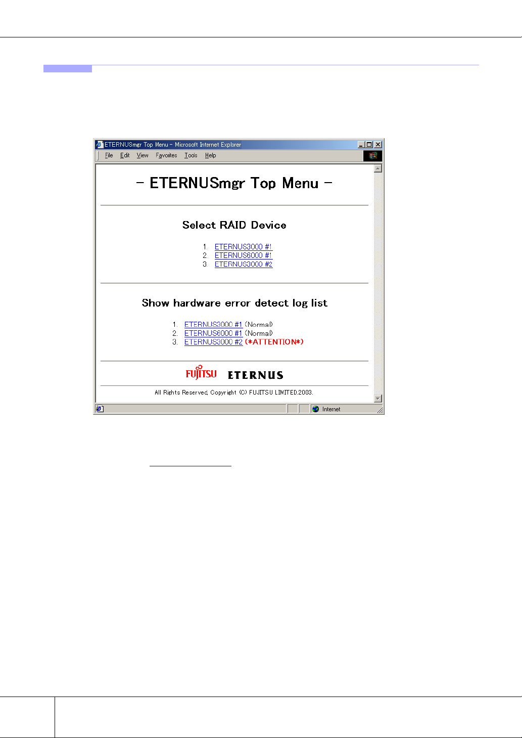
The following shows a typical ETERNUSmgr Top Menu screen.
● Select RAID Device menu
Click the name of a target device listed in the [Select RAID Device] menu to access the device's logon
screen. See "2.1
2
Logon" (page 13) for details on how to logon.
ETERNUS6000 ETERNUSmgr User Guide -Settings/Maintenance- P2X0-0230-06EN
All Rights Reserved, Copyright© FUJITSU LIMITED 2005
Page 13

Chapter 1 Operation Screens
● Show hardware error detect log list menu
Click the name of a target device listed in the [Show hardware error detect log list] menu to get a listing of the target device's error logs (alarm history files). This will require use of the Web server's list
display function. Refer to the User's Guide for the Web server being used for more details.
The status of the selected target device appears to the right of its alarm history file link. The various
statuses are described below.
Normal (Black).
Indicates that device is operating without any error.
*Offline* (Red).
Indicates that monitoring of the target device is not possible for one of the following
reasons: the ETERNUSmgr monitoring function is not active (e.g. immediately
after ETERNUSmgr installation), a problem has occurred with the target device
(e.g. power supply shutdown, no response), or a problem has occurred with the
communication link between the ETERNUSmgr server and the target device (e.g.
broken wiring, severe delays due to network overload).
The target device status will also be set to "Offline" if the Target Address
(TARGET_ADDR/TARGET_PORT) specified in the setup file is incorrect.
Check that the target device is operating normally, there is no problem with the network connection, and that the setup file details are correct.
This status will only be detected if a DETECT_OFFLINE=TRUE line is present in
the setup file. If this setting is not present, the machine will not transition from "Normal" or "ATTENTION" to "Offline".
*ATTENTION* (Bold Red).
Indicates that one or more errors have been detected in the machine.
Log in to the machine and check the location of the fault.
*BUSY* (Red).
Indicates that the device cannot respond due to device suspension, a communication error on the pathway between the device and SVP, or because a boot operation is currently in progress. Make sure that the device is operating normally and
there are no problems with the communication path between the device and SVP.
1
Caution:
The statuses displayed on the top menu reflect the information current when the top menu was last
reloaded by the Web browser. The actual current status of the target device may therefore not be
displayed until the top menu is reloaded. Always reload the top menu to check the current target
device status. Note that some Web browsers may display a previously cached page even after the
top menu is reloaded. See the manual or online help for your Web browser for details.
Note that, depending on the browser being used, "Reload" may be know as "Refresh", etc.
P2X0-0230-06EN ETERNUS6000 ETERNUSmgr User Guide -Settings/Maintenance-
All Rights Reserved, Copyright© FUJITSU LIMITED 2005
3
Page 14
1.1 Initial Screen
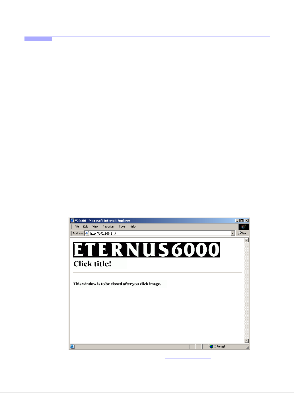
1.1.2 Using direct browser access to ETERNUSmgr Backend Program
When using operation management software other than ETERNUSmgr frontend, initial screen is title
screen of the ETERNUSmgr backend program embedded in the ETERNUS6000.
To check and maintain the ETERNUS6000, directly start the ETERNUSmgr backend program embedded
in the ETERNUS6000 from a PC on which Web browser runs. The following are applicable Web browsers.
• Web browser
- Microsoft® Internet Explorer 6.0 or later (for Windows)
- Netscape 6.0 or later (for Windows)
To access the ETERNUSmgr backend program, follow the procedures below.
1 Establish a LAN connection between the PC and the ETERNUS6000 USER
port, then start the Web browser (If the PC is connected directly to the
ETERNUS6000 USER port, a LAN cross cable will be required).
2 Input URL in the Web browser’s address bar.
This URL will vary depending on the controller firmware version. For details of your controller
firmware version, contact your maintenance engineer.
• For controller firmware versions earlier than V20L40.
Specify "http://SVP_IP_address/cgi-bin/cgi_logon.exe". (Default value: 192.168.1.2)
• For controller firmware versions V20L40 and later.
Specify "http://ETERNUS6000_IP_address/". (Default value: 192.168.1.1)
→ The title screen of the maintenance program appears.
3 Click the "ETERNUS6000" logo on the title screen.
→ ETERNUS6000 logon screen appears. See "2.1 Logon" (page 13) for details on how to logon.
4
ETERNUS6000 ETERNUSmgr User Guide -Settings/Maintenance- P2X0-0230-06EN
All Rights Reserved, Copyright© FUJITSU LIMITED 2005
Page 15
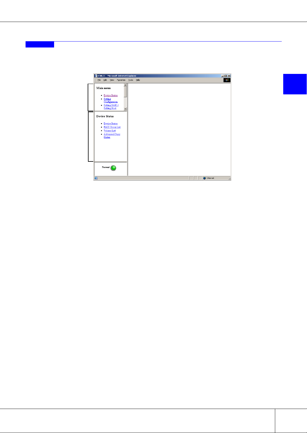
1.2 Operations Menu
The operations menu consists of a Main menu and various Submenus. Selecting an item from the Main
menu will result in the relevant list of submenu items being displayed.
Main menu
Submenu
Chapter 1 Operation Screens
1
Which menus are available will differ according to the account type. The system administrator (root) can
access various maintenance/setting menus (including the status displays), and a regular user can access the
status display menus.
The system administrator is able to access the following menus:
• Device Status menu
• Setting Configuration menu
• Setting RAID/Setting Host menu
• Miscellaneous Settings menu
• Maintenance Information menu
• Remote Support menu
• Account menu
A regular user is only able to access the Device Status menu
The following sections describe these menus.
P2X0-0230-06EN ETERNUS6000 ETERNUSmgr User Guide -Settings/Maintenance-
All Rights Reserved, Copyright© FUJITSU LIMITED 2005
5
Page 16
1.2 Operations Menu
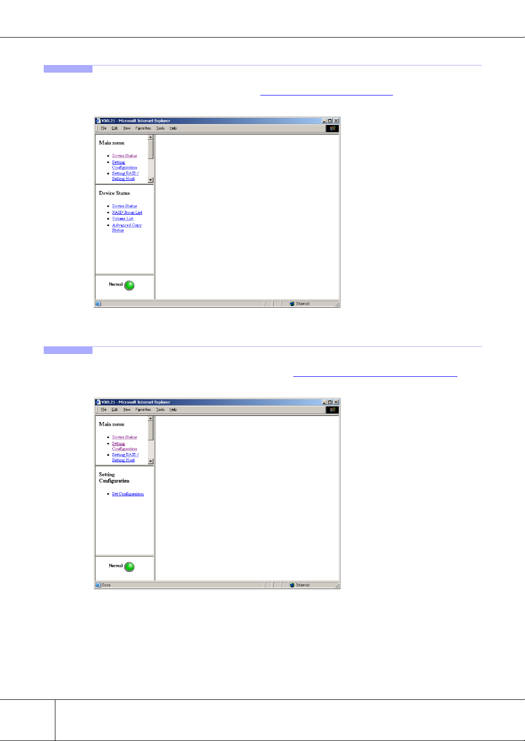
1.2.1 Device Status Menu
The Device Status menu is shown below. See "Chapter 3 Device Status" (page 17) for an explanation of its
submenus and functions.
1.2.2 Setting Configuration Menu
The Setting Configuration menu is shown below. See "Chapter 4 Setting Configuration" (page 25) for an
explanation of its submenus and functions.
6
ETERNUS6000 ETERNUSmgr User Guide -Settings/Maintenance- P2X0-0230-06EN
All Rights Reserved, Copyright© FUJITSU LIMITED 2005
Page 17
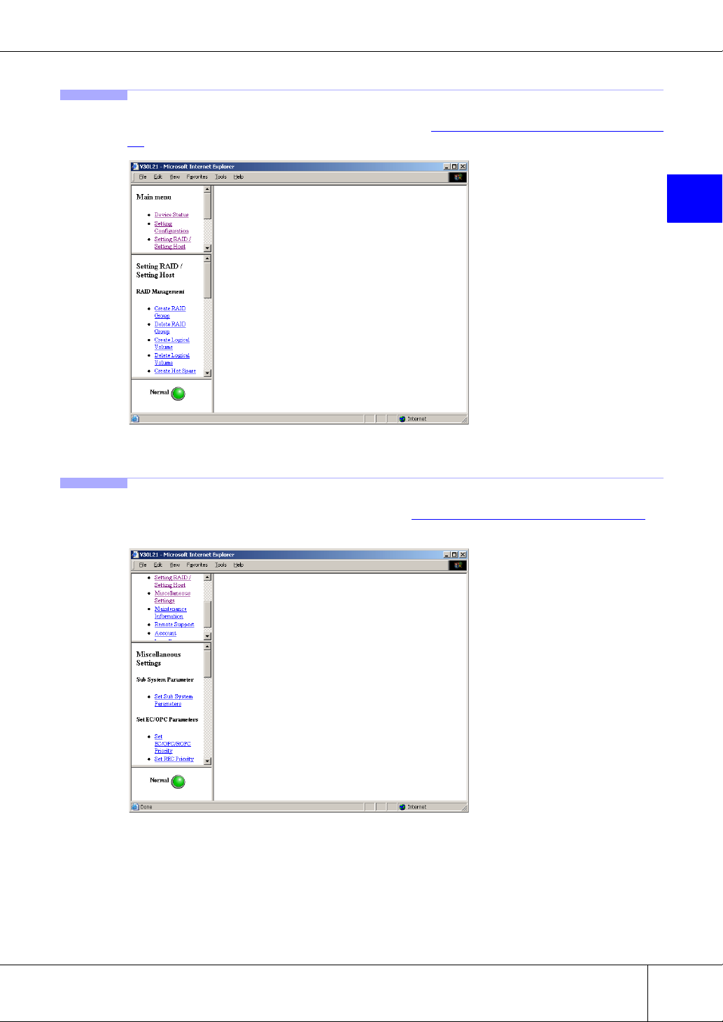
1.2.3 Setting RAID/Setting Host Menu
The Setting RAID/Setting Host menu is shown below. See "Chapter 5 Setting RAID/Setting Host" (page
27) for an explanation of its submenus and functions.
Chapter 1 Operation Screens
1
1.2.4 Miscellaneous Settings Menu
The Miscellaneous Settings menu is shown below. See "Chapter 6 Miscellaneous Settings" (page 53) for
an explanation of its submenus and functions.
P2X0-0230-06EN ETERNUS6000 ETERNUSmgr User Guide -Settings/Maintenance-
All Rights Reserved, Copyright© FUJITSU LIMITED 2005
7
Page 18
1.2 Operations Menu
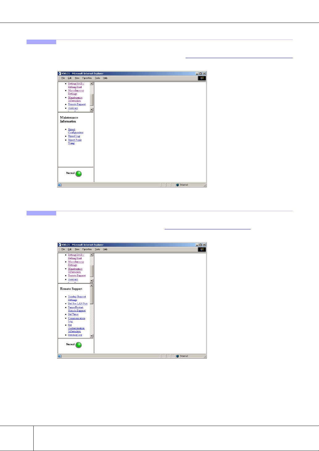
1.2.5 Maintenance Information Menu
The Maintenance Information menu is shown below. See "Chapter 7 Maintenance Information" (page 75)
for an explanation of its submenus and functions.
1.2.6 Remote Support Menu
The Remote Support menu is shown below. See "Chapter 8 Remote Support" (page 79) for an explanation
of its submenus and functions.
8
ETERNUS6000 ETERNUSmgr User Guide -Settings/Maintenance- P2X0-0230-06EN
All Rights Reserved, Copyright© FUJITSU LIMITED 2005
Page 19
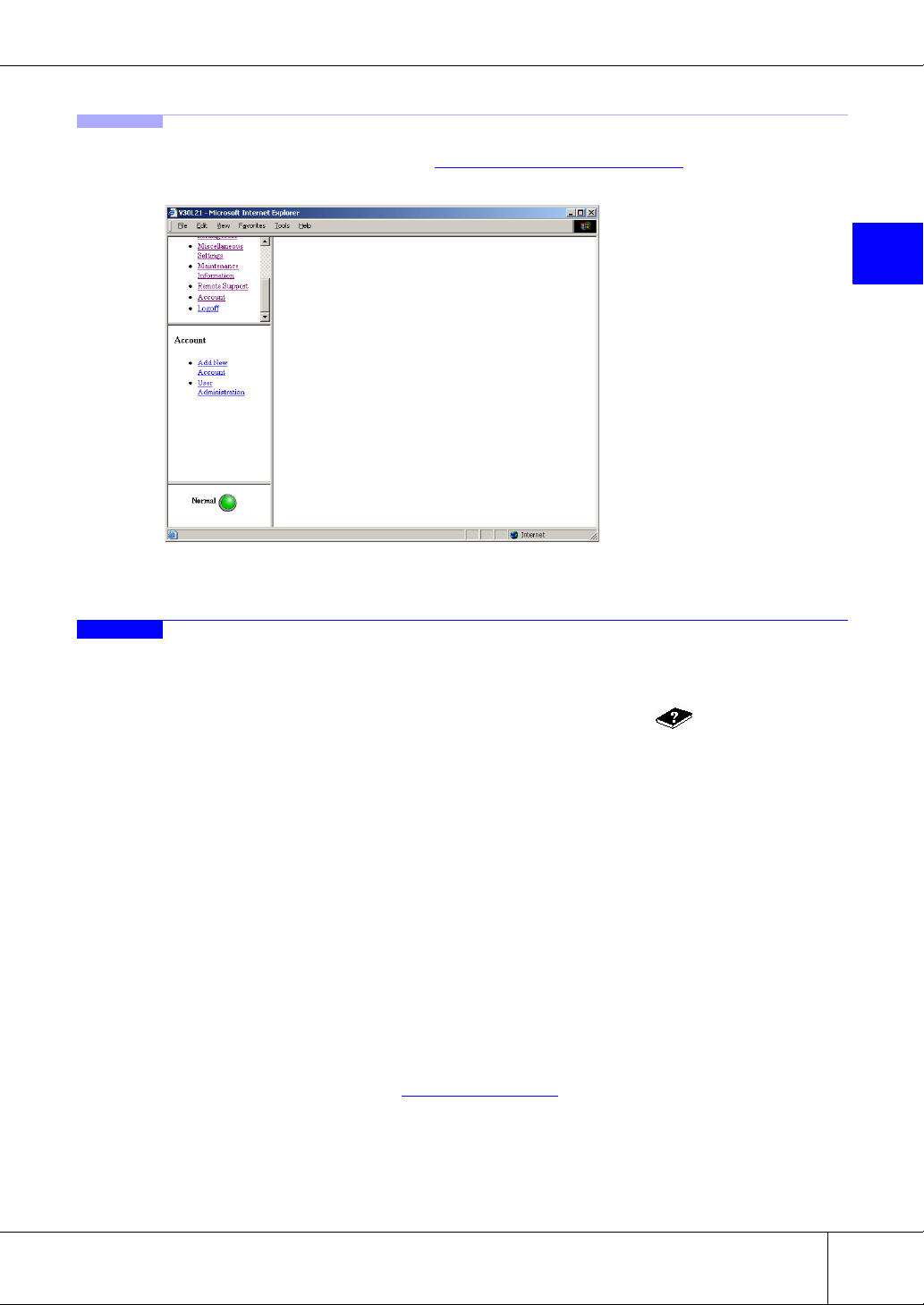
1.2.7 Account Menu
The Account menu is shown below. See "Chapter 9 User Accounts" (page 93) for an explanation of its
submenus and functions.
Chapter 1 Operation Screens
1
1.3 Screen Operations
This section describes the various screens used to setup and/or perform maintenance on the device using
ETERNUSmgr.
If you wish to view the details of a function during operation, click the [ ] button to open a help
screen.
Refer to the error messages displayed during operation in each setting window to deal with errors.
Caution:
Be careful of the following when using ETERNUSmgr.
• Unless specified otherwise, never use the Back (← ), Forward (→ ), and Close Window
(×) browser buttons. Reloading may cause program malfunction.
The window's buttons can be used to change the size of the window. However, when
Netscape is used on Solaris OE, you may need to reload if you change the window
size when logging on.
• It is recommended to set the screen resolution to 800 x 600 for a better display of contents (part names, etc.) to make it easier to perform setting and maintenance.
• It is recommended to hide the standard Web browser buttons and address bar to prevent incorrect operations while performing settings and maintenance. Once the logon
window is displayed, hide the standard Web browser buttons and address bar.
• Be sure to logoff after all necessary operations are completed. If the system administrator account is not logged off, a message will be displayed the next time you try to
logon. For details, see "2.1
• With a registered user account, you can operate only the Device Status menu.
Logon" (page 13).
P2X0-0230-06EN ETERNUS6000 ETERNUSmgr User Guide -Settings/Maintenance-
All Rights Reserved, Copyright© FUJITSU LIMITED 2005
9
Page 20

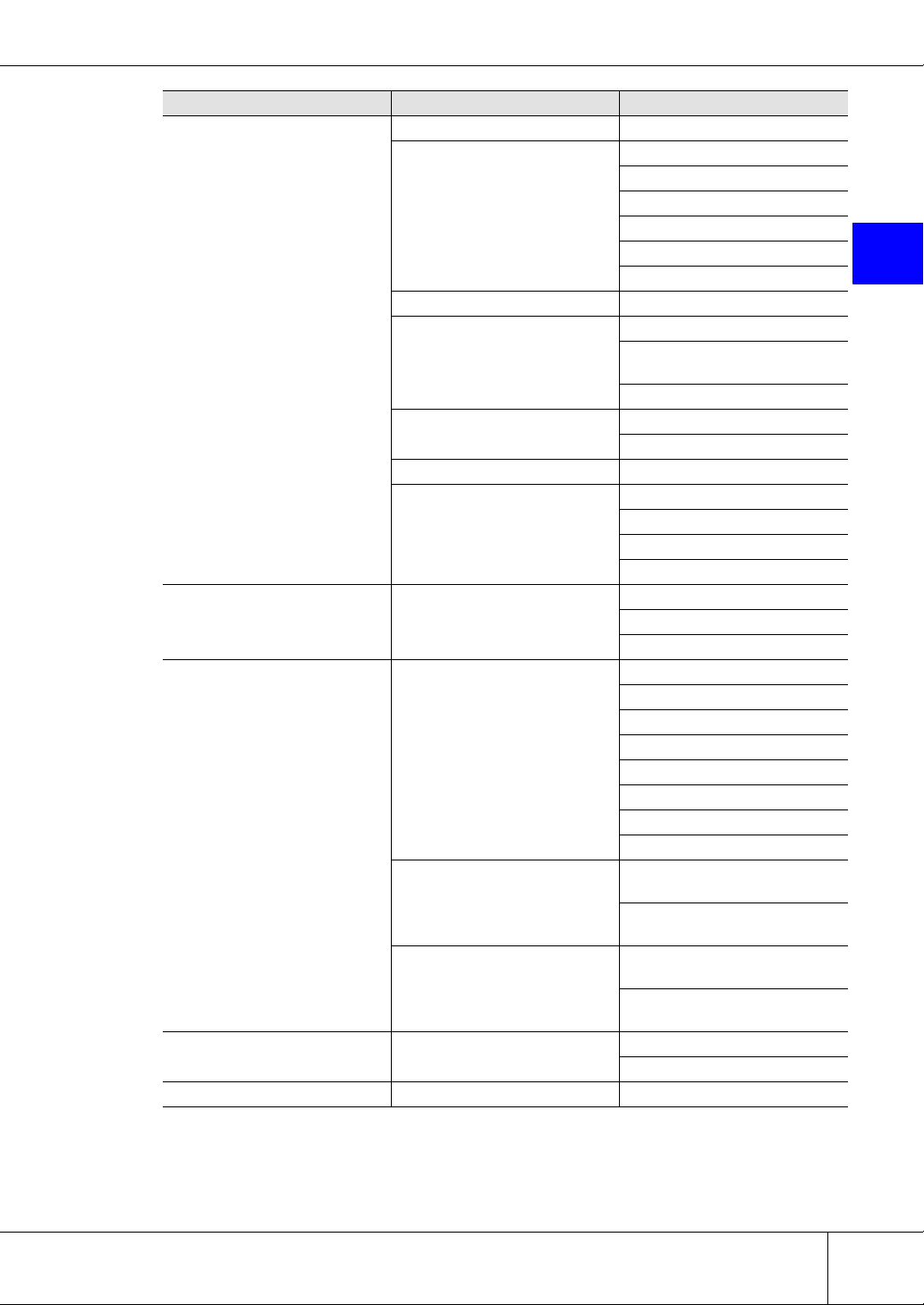
1.4 Menus and Submenus
1.4 Menus and Submenus
The following shows the ETERNUSmgr menus, submenus, and functions.
Table 1.1 List of ETERNUSmgr Menus and Functions
Main menu Submenu Screen
Logon - Logon
Device Status Device Status
Setting Configuration Setting Configuration Set Configuration
Setting RAID/Setting Host
RAID Management
Host Interface Management
Device Status
RAID Group List
Volume L ist
Advanced Copy Status
Create RAID Group
Delete RAID Group
Create Logical Volume
Delete Logical Volume
Create Hot Spare
Delete Hot Spare
Format Logical Volume
RAID Migration
Progress of RAID Migration
Set CA Parameters
Set Host WorldWideName(s)
Set Host iSCSI
Set Affinity Group
Allocate Host-Affinity Group
Set LUN Mapping
Set CA Reset Group
Set Host Response
Set Command Time-out Interval
10
ETERNUS6000 ETERNUSmgr User Guide -Settings/Maintenance- P2X0-0230-06EN
All Rights Reserved, Copyright© FUJITSU LIMITED 2005
Page 21
Chapter 1 Operation Screens
Main menu Submenu Screen
Sub System Parameter Set Sub System Parameters
Set EC/OPC/ROPC Priority
Set REC Priority
Set EC/OPC Parameters
Set RFCF Parameters Register RFCF(RBS) License
Miscellaneous Settings
Maintenance Information Maintenance Information
Remote Support
Account Account
Logoff - Logoff
SNMP
Remote Copy
Diskkey Force Initialize Diskkey
Others
Remote Support
Environment Settings
(Internet Connection/P to P Connection)
Environment Settings (Management Server Connection)
Stop EC/OPC Session
Stop REC/ROPC Session
Set EC/OPC Table Size
Register EC/OPC License
Set SNMP Agent Environment
Download Extended MIB Definition File
SNMP Trap Test
Export FCRA Information
Create FCRA Information
Set IP Address for USER Port
Set IP Address for REMCS Port
Set Date and Time
Set Box ID
Export Configuration
Export Log
Export Panic Dump
Display Support Settings
Set Use LAN Port
Pause/Restart Remote Support
Set Timer
Communication Log
Set Authentication Information
Sending Log
Import REMCS Environment
Registration (Internet/P to P
Connection)
Set REMCS Environment (Internet/P to P Connection)
Set REMCS Environment (Management Server Connection)
Registration (Management
Server Connection)
Add New Account
User Administration
1
P2X0-0230-06EN ETERNUS6000 ETERNUSmgr User Guide -Settings/Maintenance-
All Rights Reserved, Copyright© FUJITSU LIMITED 2005
11
Page 22

1.4 Menus and Submenus
12
ETERNUS6000 ETERNUSmgr User Guide -Settings/Maintenance- P2X0-0230-06EN
All Rights Reserved, Copyright© FUJITSU LIMITED 2005
Page 23

Chapter 2
Logon/Logoff
This chapter describes how to logon to and logoff from ETERNUSmgr.
2.1 Logon
Logon to ETERNUSmgr to start before starting work.
There are two types of logon accounts: user accounts and the administrator account (root).
Which menus are available will differ according to the account type.
The system administrator can access various maintenance/setting menus (including the status displays),
while a regular user can access only the status display menus.
Caution:
• The following procedures will cause an error. If this occurs, note the error message
• Depending on the type and version of the browser used, browser caching can cause
2
and either forcibly logoff any users, or retry the logon.
- Attempting to re-logon after not properly logging off from a previous session
- Attempting to logon while the system administrator is already logged on
- Attempting to logon while other applications are already logged on
problems for ETERNUSmgr.
If you are using Netscape 7.0 or later, click the "For users of Netscape 7.0 or later" link
in the logon window. Then, follow the procedures on the screen given to disable the
browser cache.
The "For users of Netscape 7.0 or later" link may not always appear, even if Netscape
7.0 or later is used, in which case the cache does not need to be disabled.
P2X0-0230-06EN ETERNUS6000 ETERNUSmgr User Guide -Settings/Maintenance-
All Rights Reserved, Copyright© FUJITSU LIMITED 2005
13
Page 24
2.1 Logon
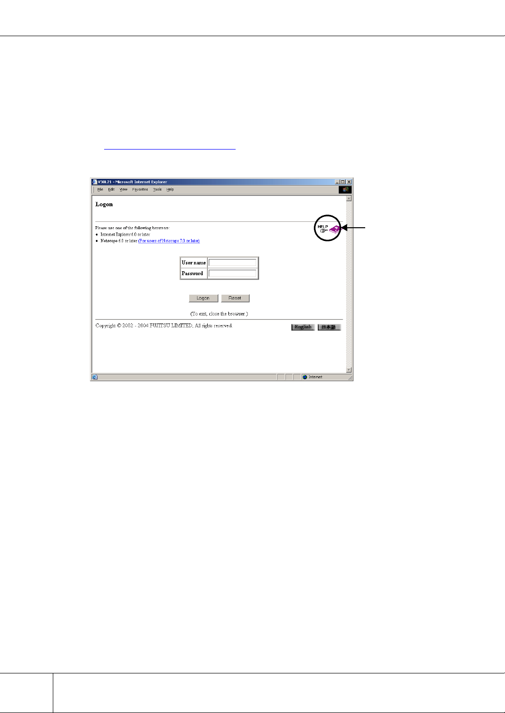
■ Logon Screen
Enter your user name and password to logon to ETERNUSmgr.
The system administrator's user name and default password are as follows.
•User Name: root
• Default Password: root
The default root password should be changed to something more secure as soon as possible!
See "Chapter 9
Refer to the help screen for subsequent operations and related notes.
User Accounts" (page 93) for an explanation of general user's user account.
Help
14
ETERNUS6000 ETERNUSmgr User Guide -Settings/Maintenance- P2X0-0230-06EN
All Rights Reserved, Copyright© FUJITSU LIMITED 2005
Page 25
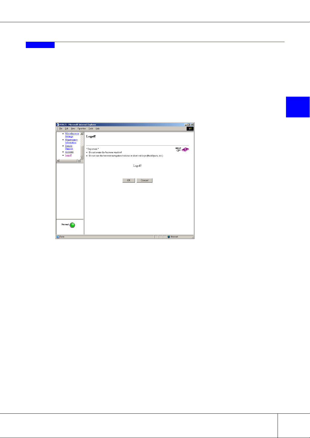
2.2 Logoff
Logoff from ETERNUSmgr and exit.
Caution:
Next time you try to logon, a message that prompts forced logon will appear if you have quit
ETERNUSmgr (closed the browser, etc.) without logging off. Make sure to logoff when you have
finished using ETERNUSmgr.
Chapter 2 Logon/Logoff
■ Logoff Screen
2
P2X0-0230-06EN ETERNUS6000 ETERNUSmgr User Guide -Settings/Maintenance-
All Rights Reserved, Copyright© FUJITSU LIMITED 2005
15
Page 26

2.2 Logoff
16
ETERNUS6000 ETERNUSmgr User Guide -Settings/Maintenance- P2X0-0230-06EN
All Rights Reserved, Copyright© FUJITSU LIMITED 2005
Page 27
Chapter 3
Device Status
This chapter describes the functions of the Device Status menu.
3.1 Device Status
The status of the controller enclosure, drive enclosures, various cables and other components of the
ETERNUS6000 may be monitored.
● Device General Status Display
The status of each of the component parts of the ETERNUS6000 is regularly monitored and the overall
status of each device is indicated by the color and status of the status lamp which is located at the lower
left of the menu screen.
Status lamp's color (green) shows the device is normal and other than green shows there is a failure in
the device. If a status lamp's color is other than green (normal), clicking the status lamp displays the
[Device Status] window for the base rack.
Device monitoring occurs at 5-minute intervals.
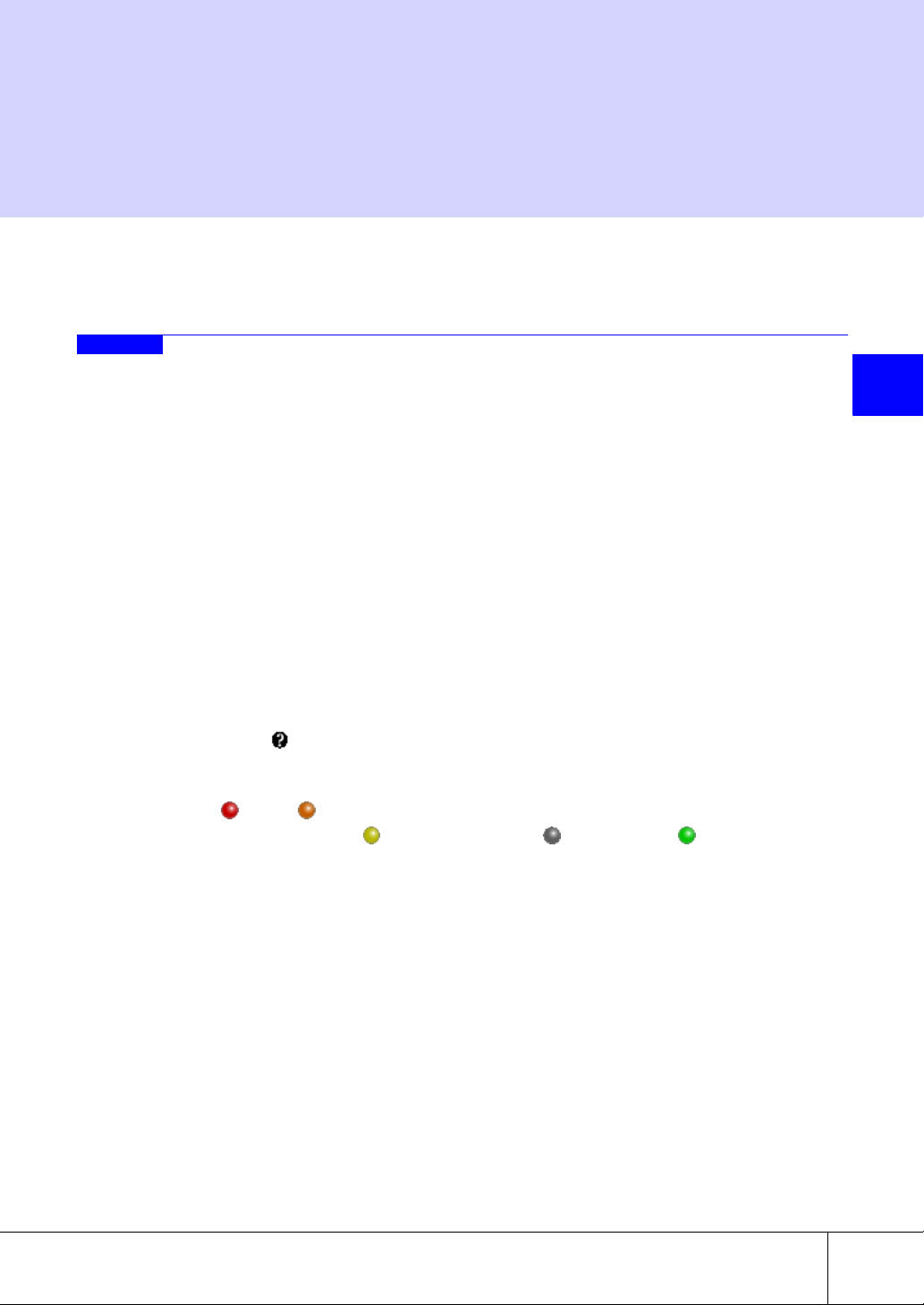
● Lamp Display Priority
The color of each [Device Status] component lamp indicates the combined status of all applicable subparts. For example, the color of the status lamp is determined by combining the status of parts such as
controller enclosure, drive enclosures and cables that make up the device. The following shows priority of status displayed by the color of the lamp. A status other than those shown below, is the lamp
error status ( ).
Priority Priority
(High) (Low)
← (Failure) - (Preventive maintenance) -
(During maintenance work) - (unused, mounted) - (Normal) →
● Model and Serial Number Display
Device model and serial number are displayed (except at logon and logoff).
3
● Device Configuration of Each Model Type
The following shows the device configuration of each ETERNUS6000 model type.
P2X0-0230-06EN ETERNUS6000 ETERNUSmgr User Guide -Settings/Maintenance-
All Rights Reserved, Copyright© FUJITSU LIMITED 2005
17
Page 28
3.1 Device Status
e
■ [Device Status] Screens
Table 3.1 Device Configuration of Each Model Type
Model type
Part
name
CM22242444
RT22244444
CA08016016016
DA22244888
DE444208322468
CPSU22242444
BTU/
BCU
Model 400/500 Model 600/700 Model 800/900 Model 1000/1100
Std
Config
33464666
Max
Config
Std
Config
Max
Config
Std
Config
Max
Config
Std
Config
Max
Config
Caution:
If the model cannot be identified, the device configuration is displayed as a model 1000 or model
1100.
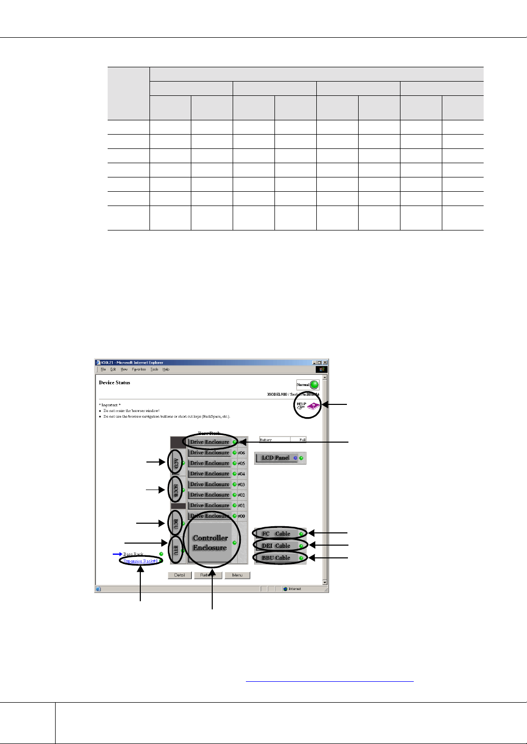
The initial [Base Rack] screen shows the status of parts installed in the ETERNUS6000 base rack. The
overall status of the base rack is indicated by the lamp located next to the [Base Rack] tag in the lower left
of the screen. Also, the status of each parts in base rack is indicated by the color of lamps.
Help
Drive Enclosur
ACD
SCCB
BCU
BTU
Expansion Rack
Controller Enclosure
FC Cable
DEI Cable
BBU Cable
18
● Overall Status in the [Device Status] Screen
The overall status of the ETERNUS6000 is indicated by the color and status of the status lamp shown
in the upper right of the [Device Status] screen. Display format and status are the same as those of the
status lamps on the menu screen. See "● Device General Status Display" (page 17).
ETERNUS6000 ETERNUSmgr User Guide -Settings/Maintenance- P2X0-0230-06EN
All Rights Reserved, Copyright© FUJITSU LIMITED 2005
Page 29
Chapter 3 Device Status
The following lists differences from the status lamp shown on the menu screens.
• The [Device Status] screen’s status lamp is not updated automatically. It is only updated
when the [Device Status] screen is opened or if the [Refresh] button is clicked.
• The status lamp on the [Device Status] screen is just a graphic. It is no a clickable button.
● Overall Status Display for Each Rack
The name of the rack whose parts' status is displayed on the screen is indicated by an arrow to its left.
The [Device Status] screen of another rack may be opened by clicking its name. The names of racks
that have not been installed are not displayed.
The overall status of each rack is indicated by the color of the lamp located to the right of the rack.
Clicking one of the controller enclosure, drive enclosure, cables, etc. buttons will open the status display screen for that part.
Clicking a part button for which [i] is displayed will show detailed information in a different browser
window.
● General Status Display for Each Part
Clicking a part button for which [i] is displayed in the parts list opens a detailed information screen.
Caution:
If the lamp shows other than normal (green), click each part button and check the status of the
component sub-parts.
3
● Part Buttons Displayed in the [Device Status] Screen
The following shows the functions that are displayed when each part button is clicked in the [Device
Status] screen.
Table 3.2 Clickable Elements of the [Device Status] Screen
Clickable element Related screen content
The status of parts mounted in the expansion racks are displayed. The
[Expansion Rack#n] link
[Controller Enclosure]
button
[Drive Enclosure] button
overall status of expansion rack is indicated by the lamp located at the
right of "Expansion Rack#1~5" at the lower left of the screen. Also, the
status of each part in the expansion rack is indicated by the color of its
lamp.
Clicking the [Controller Enclosure] button in the [Base Rack] screen
opens the [Controller Enclosure] screen.
The status of the ETERNUS6000 controller enclosure is indicated by the
color of its lamp.
The [Controller Enclosure] screen consists of a [Rear View] and a [Front
View]. Since parts such as controller boards are mounted from the rear
of the ETERNUS6000, the [Rear View] is displayed first.
You can switch between [Front View]/[Rear View].
[Front View]/[Rear View] can be displayed without scrolling the screen.
Clicking the part button for which [i] is displayed shows detailed information for the part in a different browser window.
Clicking the [Drive Enclosure] button in the [Base Rack] screen or the
[Expansion Rack] screen opens the [Drive Enclosure] screen.
The status of drive enclosures mounted in the ETERNUS6000 is indicated by the color of the lamps.
Clicking the part button for which [i] is displayed displays detailed information for the part in a different browser window.
P2X0-0230-06EN ETERNUS6000 ETERNUSmgr User Guide -Settings/Maintenance-
All Rights Reserved, Copyright© FUJITSU LIMITED 2005
19
Page 30

3.1 Device Status
Clickable element Related screen content
Clicking the [FC Cable] button in the [Base Rack] screen opens the [FC
Cable] screen.
[FC Cable] button
[DEI Cable] button
[BBU Cable] button
[ACD], [SCCB], [PCIB],
[BCU], and [BTU] buttons
The status of the FC cables connected to the ETERNUS6000 is indicated by the color of the lamps. Clicking each FC cable displays the status of each FC cable.
Each lamp color and status are the same as those of the base rack.
Clicking the [DEI Cable] button in the [Base Rack] screen opens the
[DEI Cable] screen.
The status of the DEI cables connected to the ETERNUS6000 is indicated by the color of the lamps. Clicking each DEI cable displays the
status of each DEI cable.
Each lamp color and status are the same as those of the base rack.
Clicking the [BBU Cable] button in the [Base Rack] screen opens the
[BBU Cable] screen.
The status of the BBU cables connected to the ETERNUS6000 is indicated by the color of the lamps.
Each lamp color and status are the same as those of the base rack.
Clicking the [ACD] button, [SCCB] button, [PCIB] button, [BCU] button,
or [BTU] button in the [Base Rack] screen opens the [Power Source
Base Rack Layout] screen.
The status of power-related parts of base rack that is mounted in the
ETERNUS6000 is indicated by the color of the lamps.
Clicking the part button for which [i] is displayed displays detailed information for the part in a different browser window.
Refer to the help screens for subsequent operations and related notes.
Caution:
When downloading a WWN list or a disk drive list, the file must be saved within a minute of the
[Download] button being clicked.
If the download dialog box is left open for a minute or more, the download operation may terminate with an unsuccessfully downloaded file.
If the downloaded file cannot be opened, the download has probably failed, in which case try
downloading again.
20
ETERNUS6000 ETERNUSmgr User Guide -Settings/Maintenance- P2X0-0230-06EN
All Rights Reserved, Copyright© FUJITSU LIMITED 2005
Page 31

3.2 RAID Group List
A list of all the RAID groups that have been created on the ETERNUS6000 and their details may be displayed.
The RAID Group List function is used to list the RAID groups that have been created by the system
administrator, and also shows the status of the logical volumes within each RAID group.
Note:
• The progress of volume formatting can be checked from the [Logical Volume List]
screen of the target RAID group in a manner similar to the Volume List function.
• The Volume List function may be used to display all logical volumes that are known to
the device.
Chapter 3 Device Status
■ [RAID Group List] Screen
This shows the RAID groups that have been setup in the ETERNUS6000.
While a RAID group is rebuilding/copying back, progress of the rebuild/copy back process can be checked
in a different browser window from the [RAID Group List] screen.
Refer to the help screen for subsequent operations and related notes.
Help
3
P2X0-0230-06EN ETERNUS6000 ETERNUSmgr User Guide -Settings/Maintenance-
All Rights Reserved, Copyright© FUJITSU LIMITED 2005
21
Page 32

3.3 Volume List
3.3 Volume List
The current status of all volumes contained in the ETERNUS6000 may be checked.
ETERNUS6000 provides a function that enables multiple volumes to be combined and configured as one
volume.
The Volume List function is used to display the volume-side status of all the ETERNUS6000 volumes.
Note:
■ [Volume List] Screen
This displays the status of all volumes in the ETERNUS6000.
Refer to the help screen for subsequent operations and related notes.
The progress of volume formatting can be checked from the [Volume List] screen in a manner similar to the [Logical Volume List] screen of the RAID Group List function.
Help
22
ETERNUS6000 ETERNUSmgr User Guide -Settings/Maintenance- P2X0-0230-06EN
All Rights Reserved, Copyright© FUJITSU LIMITED 2005
Page 33

3.4 Advanced Copy Status
The ongoing status of Advanced Copy functions, such as EC (Equivalent Copy), OPC (One Point Copy),
REC (Remote Equivalent Copy) and ROPC (Remote One Point Copy) may also be monitored.
Caution:
• When there is no EC, OPC, REC or ROPC session current, a message to that effect
appears. Click the [OK] button to return to the [Menu] screen.
• When all FCRA modes of the ETERNUS6000 are "Target", the path status cannot be
checked. The FCRA path status must be checked from the remote device.
■ [Advanced Copy Status] Screen
This shows the number and status of EC, OPC, REC and ROPC active sessions and the status of the FCRA
paths. Use the radio buttons to select a copy type or remote Box ID and display the matching session list or
the path status of the ETERNUS6000 and the remote devices.
Refer to the help screen for subsequent operations and related notes.
Chapter 3 Device Status
3
Help
P2X0-0230-06EN ETERNUS6000 ETERNUSmgr User Guide -Settings/Maintenance-
All Rights Reserved, Copyright© FUJITSU LIMITED 2005
23
Page 34

3.4 Advanced Copy Status
24
ETERNUS6000 ETERNUSmgr User Guide -Settings/Maintenance- P2X0-0230-06EN
All Rights Reserved, Copyright© FUJITSU LIMITED 2005
Page 35

Chapter 4
Setting Configuration
This chapter describes the functions of the [Setting Configuration] menu.
4.1 Set Configuration
Configuration/setting information may be sent to and applied by the ETERNUS6000. This may be either
the current configuration/settings information, the configuration/settings information that was sent last
time, or the time before that, or configuration/settings information contained in a user specified file.
Caution:
• Never execute the Set Configuration function while the ETERNUS6000 volumes are
being accessed or while an Advanced Copy session (EC/OPC/REC/ROPC) is in
progress.
• The ETERNUS6000 must be power cycled (off/on) to enable the configuration/setting
information set with this function. The sent configuration/setting information is only
applied after the ETERNUS6000 is restarted.
• If [Initialize Mode] is selected, it will be necessary to (re)format all volumes after the
ETERNUS6000 has been power cycled (off/on). Volumes which have not been (re)formatted cannot be used.
• If the ETERNUS6000 model type and the model type set in the uploaded configuration/setting information file do not match, the configuration/settings information cannot
be applied.
4
P2X0-0230-06EN ETERNUS6000 ETERNUSmgr User Guide -Settings/Maintenance-
All Rights Reserved, Copyright© FUJITSU LIMITED 2005
25
Page 36

4.1 Set Configuration
■ [Set Configuration] Screen
Used to select the configuration mode and the configuration file that are to be applied to the
ETERNUS6000.
Refer to the help screen for subsequent operations and related notes.
Help
Caution:
The configuration information file must be saved within a minute of clicking one of the three
[Configuration] links.
If the download dialog box is left open for a minute or more, the download operation may terminate with an unsuccessfully downloaded file.
If the downloaded file cannot be opened, the download has probably failed, in which case try
downloading again.
26
ETERNUS6000 ETERNUSmgr User Guide -Settings/Maintenance- P2X0-0230-06EN
All Rights Reserved, Copyright© FUJITSU LIMITED 2005
Page 37

Chapter 5
Setting RAID/Setting Host
This chapter describes the functions of the Setting RAID/Setting Host menu.
5.1 RAID Management
5.1.1 Create RAID Group
RAID groups may be created without having to stop the ETERNUS6000.
The initial set of RAID groups are created in the factory, however if you wish to change the RAID setup or
add extra disk drives, then new RAID groups will need to be created. The created groups can be checked
using the "RAID Group List" function in the [Device Status] menu.
Caution:
• Only data disk drives that are not already assigned to a RAID group can be used.
• Use disk drives that all have the same capacity when creating a RAID group. If different sized disk drives are used, then all the disk drives in the RAID group will be considered to be the same size as the smallest assigned disk drive, with any excess disk
space on the larger disk drives unusable and wasted.
5
Note:
After creating a RAID group, use the Create Logical Volume function to assign it a volume set.
■ [Create RAID Group] Screen
Used to create a RAID group from any unused disk drives that are free to be assigned.
Caution:
If there are no disk drives that can be assigned to the RAID group, a message to that effect appears.
To create the RAID group, first add some disk drives and then try "Create RAID Group" again.
P2X0-0230-06EN ETERNUS6000 ETERNUSmgr User Guide -Settings/Maintenance-
All Rights Reserved, Copyright© FUJITSU LIMITED 2005
27
Page 38

5.1 RAID Management
Refer to the help screen for subsequent operations and related notes.
~~
Help
5.1.2 Delete RAID Group
Existing RAID groups may be deleted without having to stop the ETERNUS6000.
Caution:
• RAID groups with associated volumes cannot be deleted. A RAID group with associ-
• For details, see "5.1.4
28
ated volumes may be made deletable by first deleting the volume mappings, then
deleting the volumes themselves.
Delete Logical Volume" (page 31).
ETERNUS6000 ETERNUSmgr User Guide -Settings/Maintenance- P2X0-0230-06EN
All Rights Reserved, Copyright© FUJITSU LIMITED 2005
Page 39

Chapter 5 Setting RAID/Setting Host
■ [Delete RAID Group] Screen
A list of all the ETERNUS6000 RAID groups is displayed. Select the check box(es) of whichever RAID
group or groups you wish to be deleted.
Caution:
• If the ETERNUS6000 has no RAID groups, a message to that effect appears.
• A check box is not displayed for a RAID group if it has associated volumes. Before a
RAID group can be deleted, its volumes must be deleted first.
Refer to the help screen for subsequent operations and related notes.
Help
5
5.1.3 Create Logical Volume
Volumes may be created on a RAID group without having to stop the ETERNUS6000.
Volumes may be created in one of three ways. "Register Logical volume" creates a single volume while
"RAID Consolidation" and "MVV Concatenation" combine multiple volumes to make one big volume.
After the volume creation process has completed, the volumes will be formatted automatically.
Creating a volume on a RAID group and mapping it allows it to be accessed by the host.
The maximum number of volumes that can be created on a RAID group is determined by the volume type
and disk drive type.
Different types of volumes cannot be used within the same RAID group.
P2X0-0230-06EN ETERNUS6000 ETERNUSmgr User Guide -Settings/Maintenance-
All Rights Reserved, Copyright© FUJITSU LIMITED 2005
29
Page 40

5.1 RAID Management
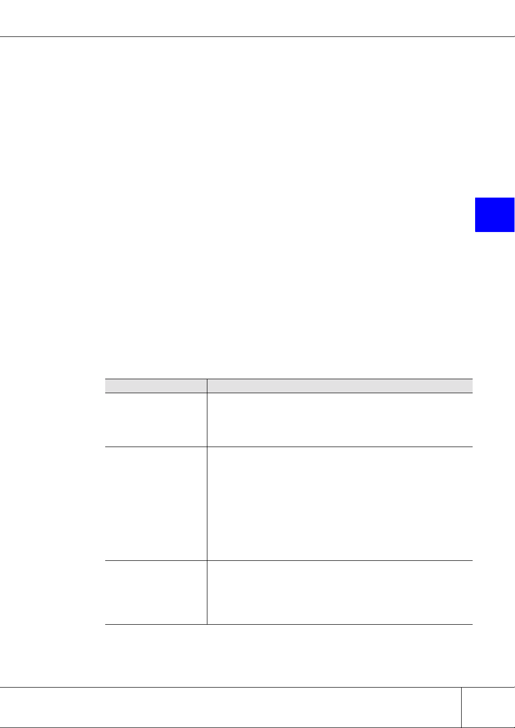
■ [Create Logical Volume] Screen (Method Selection)
Select which method is to be used to create the volume.
A list of all the existing ETERNUS6000 logical volumes appears in the screen. Select [Register Logical
volume] to make a single new volume. Select [RAID Consolidation] to combine free space from multiple
RAID groups to make an open combined volume. Select [MVV Concatenation] to combine MVV volumes
from the same RAID group to make an MVV combined volume.
If no volumes has been created yet, or the maximum number of volumes have already been created on the
ETERNUS6000, a message to that effect appears.
Caution:
• If the maximum number of volumes have already been created on the
ETERNUS6000, [Register Logical volume] and [RAID Consolidation] will not be displayed. To create a new volume, first delete a volume with "Delete Logical Volume"
and then try "Create Logical Volume" again.
• If the ETERNUS6000 does not already contain two or more MVV volumes, [MVV Concatenation] is not displayed. To create an MVV combined volume, create two or more
MVV volumes on the device using the "Create Logical Volume" function [Register Logical volume] and then click [MVV Concatenation].
Help
30
ETERNUS6000 ETERNUSmgr User Guide -Settings/Maintenance- P2X0-0230-06EN
All Rights Reserved, Copyright© FUJITSU LIMITED 2005
Page 41
Chapter 5 Setting RAID/Setting Host
■ [Create Logical Volume] Screen (Volume Creation)
All the existing ETERNUS6000 RAID groups are displayed on this screen. Select the radio button of the
RAID group on which the volume is to be created.
Refer to the help screen for subsequent operations and related notes.
Help
5
5.1.4 Delete Logical Volume
Existing volumes may be deleted without having to stop the ETERNUS6000.
Both simple volumes and combined volumes can be deleted.
Caution:
• Before deleting a volume, you must first delete its mapping.
If the CA is FCCA or iSCSI, and you are using "Set LUN Mapping", delete the mapping information using the Set LUN Mapping function. If using the "Host Affinity function", delete the mapping information using the Set Affinity Group function.
If mapping information exists when a volume is deleted, the mapping information is
automatically deleted.
• Volumes which are subject to an EC/OPC/REC/ROPC session cannot be deleted.
Attempting to delete such a volume causes an error message to be displayed. An
error message is also displayed if such volumes are included in the target selection. In
this case, the volumes included in the target selection are not deleted.
Which volumes are currently subject to an EC/OPC/REC/ROPC session can be
checked with the Advanced Copy Status function.
P2X0-0230-06EN ETERNUS6000 ETERNUSmgr User Guide -Settings/Maintenance-
All Rights Reserved, Copyright© FUJITSU LIMITED 2005
31
Page 42

5.1 RAID Management
■ [Delete Logical Volume] Screen
A list of all the ETERNUS6000 logical volumes appears. Select the check box of whichever volume or
volumes you wish to delete. Deleting a combined volume will delete all its component volumes.
Refer to the help screen for subsequent operations and related notes.
Help
32
ETERNUS6000 ETERNUSmgr User Guide -Settings/Maintenance- P2X0-0230-06EN
All Rights Reserved, Copyright© FUJITSU LIMITED 2005
Page 43

5.1.5 Create Hot Spare
Hot spare disks (available to substitute for a failed disk drive) may be assigned without having to stop the
ETERNUS6000.
An assigned hot spare disk can be used by any RAID group. Rebuilding starts automatically when a disk
drive failure occurs. When the failed disk drive is replaced with a new disk drive, data is copied back to the
new disk drive. Then the hot spare disk that was substituting for the failed disk drive returns to being a
spare disk again.
Caution:
• System disks cannot be assigned as hot spare disks.
• To substitute for a failed disk drive a hot spare disk must have the same or a larger
capacity than the disk drive it is replacing. Any disk drive assigned as a hot spare disk
should be the same size as or larger than the largest data disks.
• Each FC-Loop must contain at least one hot spare disk. This may be installed in any
of the FC-Loop’s drive enclosures (DE). A hot spare disk can only be used in place of
a failed disk drive if both are in the same FC-Loop.
Note:
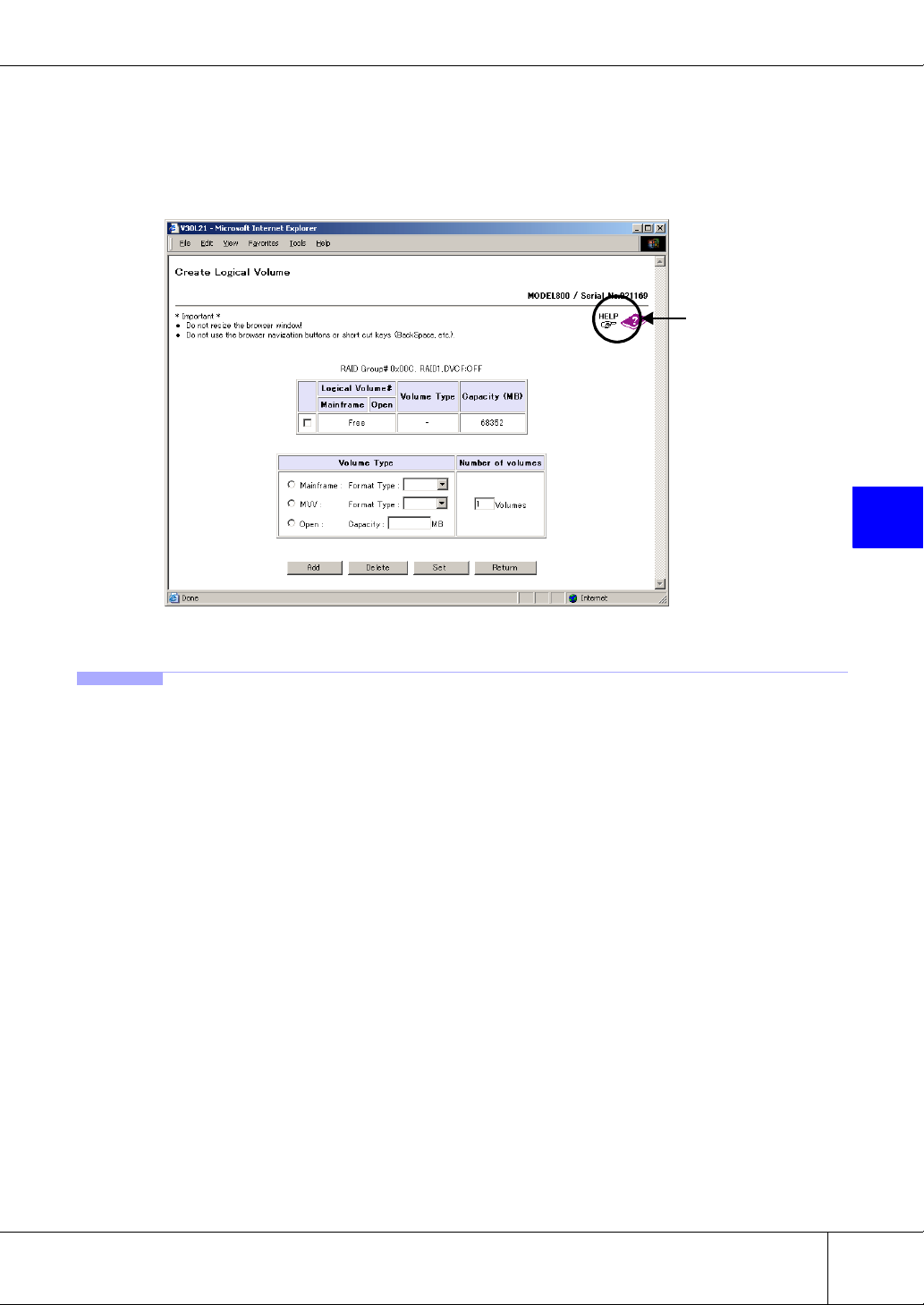
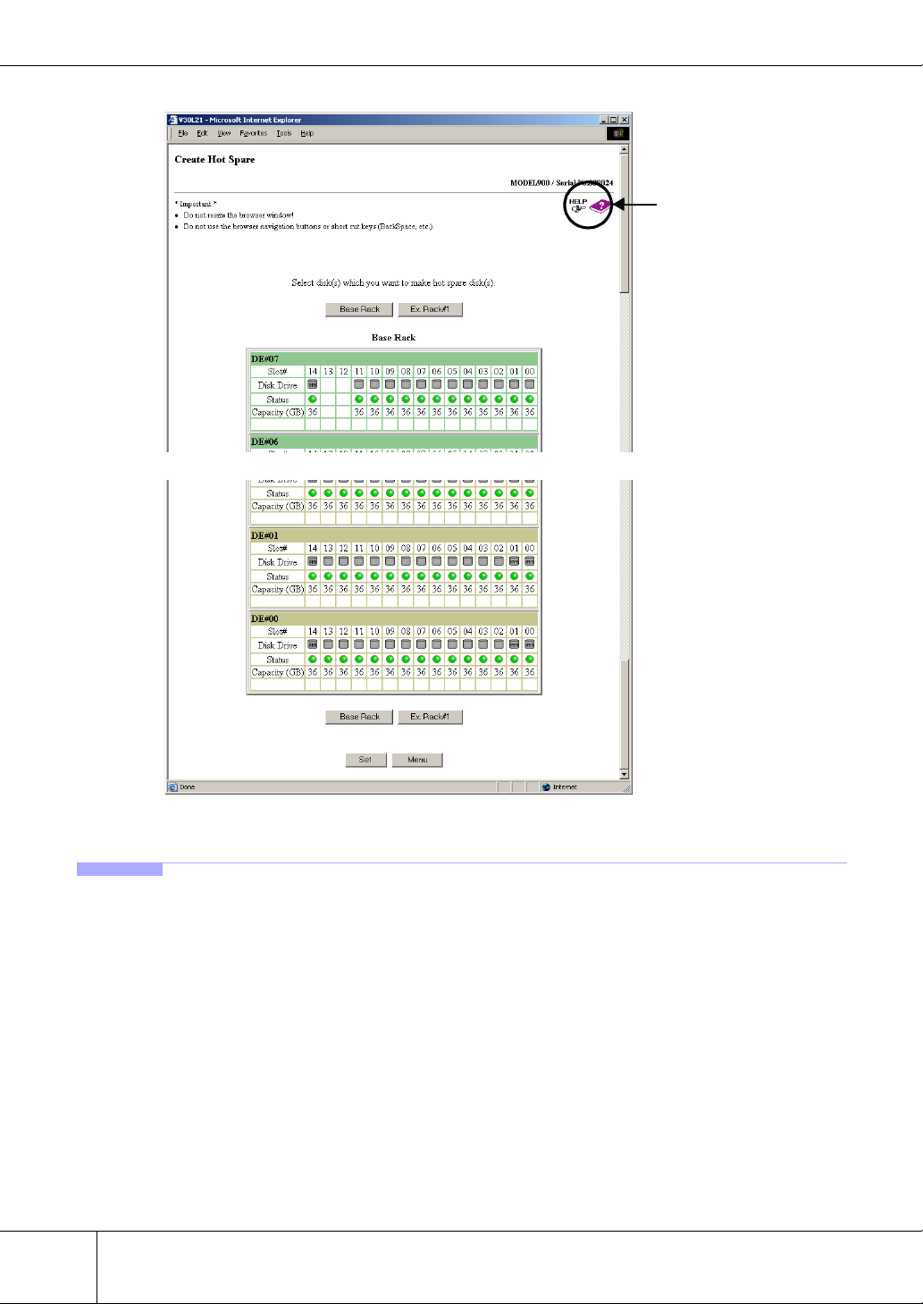
Assign the disk drive installed in the last slot (Slot#14) of each drive enclosure (DE) as a hot spare
disk. If multiple hot spare disks are assigned, it is recommended that the disks installed in the slots
next to the last slot (i.e. next Slot#13, then Slot#12, etc.) be used.
Chapter 5 Setting RAID/Setting Host
5
■ [Create Hot Spare] Screen
The current hot spare status of all disk drives in a given rack is displayed. Select the check boxes of the
disk drives you wish to assign as hot spare disks.
Caution:
If no disk drives are available to be assigned as hot spare disks, a message to that effect appears.
In this case, hot spare disks may be assigned by first adding some new disk drives and then trying
"Create Hot Spare" again.
P2X0-0230-06EN ETERNUS6000 ETERNUSmgr User Guide -Settings/Maintenance-
All Rights Reserved, Copyright© FUJITSU LIMITED 2005
33
Page 44
5.1 RAID Management
Refer to the help screen for subsequent operations and related notes.
~~
Help
5.1.6 Delete Hot Spare
Existing hot spare disks may be unassigned without having to stop the ETERNUS6000.
After "deleting" a hot spare disk, the disk drive can be built into a RAID group and used as a data disk.
Caution:
■ [Delete Hot Spare] Screen
The current hot spare status (deletable, not deletable) of all disks in a given rack is displayed. Select the
check boxes of the hot spare disks (that you wish to delete).
Caution:
34
An in-use The hot spare disk (one that is in for a failed disk drive).
When there are no hot spare disks that can be deleted, a message to that effect appears.
ETERNUS6000 ETERNUSmgr User Guide -Settings/Maintenance- P2X0-0230-06EN
All Rights Reserved, Copyright© FUJITSU LIMITED 2005
Page 45

Chapter 5 Setting RAID/Setting Host
Refer to the help screen for subsequent operations and related notes.
Help
~~
5
5.1.7 Format Logical Volume
Volumes need to be formatted to allow access by the host servers.
Formatting is performed on whole logical volumes and takes a short time to complete. The volume can be
used as soon as formatting has completed.
Caution:
• The Format Logical Volume function can format all logical volumes in the device. Formatting the volume in use will delete its data.
• After volumes are created using the "Create Logical Volume" function, they are formatted automatically. In this case it is not necessary to format them using the "Format
Logical Volume" function.
Note:
Progress of the formatting process can be checked using the Volume List function and RAID
Group List function.
P2X0-0230-06EN ETERNUS6000 ETERNUSmgr User Guide -Settings/Maintenance-
All Rights Reserved, Copyright© FUJITSU LIMITED 2005
35
Page 46

5.1 RAID Management
■ [Format Logical Volume] Screen
Select which method of volume formatting is to be used.
Refer to the help screen for subsequent operations and related notes.
5.1.8 RAID Migration
Help
Volumes may be from one RAID group to an equivalent free area on another RAID group.
Moving volumes using the "RAID Migration" function allows distribution of loads and RAID level conversion. Since the "RAID Migration" function automatically creates a new volume, performs formatting,
and establishes the host interface, users can access data without having to be aware of volume movement.
The original volume is deleted after the migration process has completed.
● Conditions for RAID Migration
• Only open type volumes can be migrated.
• Up to 32 migrations can be performed at the same time.
• Total of 2TB of volumes can be migrated at the same time.
• The migration source and migration destination must be single volumes that are not subject to the "RAID Consolidation" function.
Caution:
• Migration cannot be performed in the following cases.
- When there are no volumes that can be migrated
- When the ETERNUS6000 model type cannot be identified
- When the maximum number of volumes already exists on the ETERNUS6000
- When 32 other migrations are already running
- When a total of 2TB of migrations are already running
- When the size of the smallest volume that is currently available for migration is larger than
the remaining migration capacity (= 2TB - total size of all current migration)
• The Migration function cannot be used for volumes that are set for extent setting by
the bind-in-cache function. Please contact your system administrator to delete extent
information for the relevant volumes first, before executing RAID Migration.
If extent information was deleted, extent setting is required for migration destination
volumes after RAID Migration.
36
ETERNUS6000 ETERNUSmgr User Guide -Settings/Maintenance- P2X0-0230-06EN
All Rights Reserved, Copyright© FUJITSU LIMITED 2005
Page 47

Chapter 5 Setting RAID/Setting Host
• Device configuration information is required if it becomes necessary to restore the
ETERNUS6000 to a previous state. Collect this configuration information using the
"Export Configuration" function after the migration has completed.
Note:
Migration progress can be checked with the "Progress of RAID Migration" function.
■ [RAID Migration] Screen
A list of all the ETERNUS6000 volumes is displayed. Use the radio buttons to select the volume that is to
be migrated.
Refer to the help screen for subsequent operations and related notes.
Help
5
P2X0-0230-06EN ETERNUS6000 ETERNUSmgr User Guide -Settings/Maintenance-
All Rights Reserved, Copyright© FUJITSU LIMITED 2005
37
Page 48

5.1 RAID Management
5.1.9 Progress of RAID Migration
The status of current "RAID Migration" sessions is displayed.
This function enables users to check the current status of each migration, but can also be used to stop inprogress migrations.
Caution:
• When there are no migrations currently in progress, a message to that effect appears.
Click the [OK] button to return to the [Menu] screen.
• Device configuration information is required if it becomes necessary to restore the
ETERNUS6000 to a previous state. Collect this configuration information using the
"Export Configuration" function after all migrations have completed.
Note:
• Use the "RAID Migration" function to perform the actual migration.
• Up to 32 migrations can be performed at the same time.
■ [Progress of RAID Migration] Screen
The progress of the migration process is displayed for each current migration ID. A migration can be cancelled, or the current status of a migration can be updated from this screen.
Refer to the help screen for subsequent operations and related notes.
Help
38
ETERNUS6000 ETERNUSmgr User Guide -Settings/Maintenance- P2X0-0230-06EN
All Rights Reserved, Copyright© FUJITSU LIMITED 2005
Page 49

5.2 Host Interface Management
5.2.1 Set CA Parameters
A connection may be setup between a CA (Channel Adapter) and a host without having to stop the
ETERNUS6000. If the type of CA is the same, the settings can be copied for use by another CA.
Caution:
Before changing the detailed settings of an active CA or CA port, be sure to cut-off access to it
from all hosts.
When changing the detailed settings of a newly added CA, it is not necessary to cut-off access to it
from all hosts.
■ [Set CA Parameters] Screen
A list of CAs installed in the ETERNUS6000 is displayed by mounting positions (RT#xx CA#y). Select
the CA whose detailed settings are to be adjusted. If the target CA is FCCA, FCRA, or iSCSI, each CA
port will need to be setup individually.
Click on the CA or CA port that is to be setup.
Chapter 5 Setting RAID/Setting Host
5
Refer to the help screen for subsequent operations and related notes.
Help
P2X0-0230-06EN ETERNUS6000 ETERNUSmgr User Guide -Settings/Maintenance-
All Rights Reserved, Copyright© FUJITSU LIMITED 2005
39
Page 50

5.2 Host Interface Management
5.2.2 Set Host WorldWideName(s)
Host World Wide Names related to the device's Host Affinity function may be added or deleted without
having to stop the ETERNUS6000.
Host World Wide Name is used to limit which hosts can access the ETERNUS6000's logical volumes, in
that only those host bus adapters which have a Host World Wide Name registered are allowed access to the
ETERNUS6000.
Set a Host World Wide Name only when the hosts and the ETERNUS6000 are connected via FCCA.
When a host response from the ETERNUS6000 to the hosts needs to be changed, it can be set either per
Host World Wide Name or per FCCA port by setting the "Host Affinity" function [ON/OFF].
• When the "Host Affinity" function is [ON]
Using this function, set the host responses on a per Host World Wide Name basis.
• When the "Host Affinity" function is [OFF]
Using the "Set CA parameters" function, set the host responses on a per FCCA port basis.
Caution:
• A Host World Wide Name that is in use should not be deleted from its FCCA port.
Before deleting a Host World Wide Name, all user accesses to it must be terminated.
Note that when adding a Host World Wide Name, user accesses need not be terminated.
• The Host Affinity function can be used when [Affinity Mode] of the target FCCA port is
set to [ON (Enabled)].
• When a host response is deleted using the "Set Host Response" function, the host
response for the Host World Wide Name related to the deleted host response is reset
to the default pattern.
Note:
• There are two types of methods to enable device logical volumes to be recognized
from a host when the host and the ETERNUS6000 are connected via FCCA. One is
"Set LUN Mapping" and the other is Host Affinity function that requires "Set Host
WorldWideName(s)", "Set Affinity Group" and "Allocate Host-Affinity Group". [Affinity
Mode] of "Set CA parameters" set for each FCCA port determines which function is
enabled. When [Affinity Mode] is set to [ON (Enabled)], the Host Affinity function is
enabled, and when [Affinity Mode] is set to [OFF (Disabled)], the "Set LUN Mapping"
enabled.
• The Host Affinity function is a security function for hosts, which is realized by using
FCCA (CA for Fibre Channel) or iSCSI. Not only "Set Host WorldWideName(s)" but
also "Set Affinity Group" and "Allocate Host-Affinity Group" are required to use the
Host Affinity function for FCCA.
• If no appropriate host response has been set in the ETERNUS6000, use the "Set Host
Response" function to create one.
40
ETERNUS6000 ETERNUSmgr User Guide -Settings/Maintenance- P2X0-0230-06EN
All Rights Reserved, Copyright© FUJITSU LIMITED 2005
Page 51

Chapter 5 Setting RAID/Setting Host
■ [Set Host WorldWideName(s)] Screen
Displays a list of Host World Wide Names set on the ETERNUS6000. This screen can also be used to add
or delete a Host World Wide Name. Up to 256 Host World Wide Names can be set on the ETERNUS6000.
Refer to the help screen for subsequent operations and related notes.
Help
5
5.2.3 Set Host iSCSI
Host iSCSI entries related to the device's Host Affinity function may be added or deleted without having to
stop the ETERNUS6000.
Host iSCSI entries are used to limit which hosts can access the ETERNUS6000's logical volumes, in that
only those host bus adapters which have a Host iSCSI entry registered are allowed access to the
ETERNUS6000.
Set a Host iSCSI entry only when the hosts and the ETERNUS6000 are connected via iSCSI.
When a host response from the ETERNUS6000 to the hosts needs to be changed, it can be set either per
Host iSCSI entry or per iSCSI port by setting the "Host Affinity" function [ON/OFF].
• When the "Host Affinity" function is [ON]
Using this function, set the host responses on a per Host iSCSI entry basis.
• When the "Host Affinity" function is [OFF]
Using the "Set CA parameters" function, set the host responses on a per iSCSI port basis.
P2X0-0230-06EN ETERNUS6000 ETERNUSmgr User Guide -Settings/Maintenance-
All Rights Reserved, Copyright© FUJITSU LIMITED 2005
41
Page 52

5.2 Host Interface Management
Caution:
• A Host iSCSI entry that is in use should not be deleted from its iSCSI port. Before
deleting a Host iSCSI entry, all user accesses to it must be terminated. Note that when
adding a Host iSCSI entry, user accesses need not be terminated.
• The Host Affinity function can be used when [Affinity Mode] of the target iSCSI port is
set to [ON (Enabled)].
• When a host response is deleted using the "Set Host Response" function, the host
response for the Host iSCSI entry related to the deleted host response is reset to the
default pattern.
Note:
• There are two types of methods to enable device logical volumes to be recognized
from a host when the host and the ETERNUS6000 are connected via iSCSI. One is
"Set LUN Mapping" and the other is Host Affinity function that requires "Set Host
iSCSI", "Set Affinity Group" and "Allocate Host-Affinity Group". [Affinity Mode] of "Set
CA parameters" set for each iSCSI port determines which function is enabled. When
[Affinity Mode] is set to [ON (Enabled)], the Host Affinity function is enabled, and when
[Affinity Mode] is set to [OFF (Disabled)], the "Set LUN Mapping" enabled.
• The Host Affinity function is a security function for hosts, which is realized by using
FCCA (CA for Fibre Channel) or iSCSI. Not only "Set Host iSCSI" but also "Set Affinity
Group" and "Allocate Host-Affinity Group" are required to use the Host Affinity function
for iSCSI.
• If no appropriate host response has been set in the ETERNUS6000, use the "Set Host
Response" function to create one.
42
ETERNUS6000 ETERNUSmgr User Guide -Settings/Maintenance- P2X0-0230-06EN
All Rights Reserved, Copyright© FUJITSU LIMITED 2005
Page 53

Chapter 5 Setting RAID/Setting Host
■ [Set Host iSCSI] Screen
Displays a list of Host iSCSI entries set on the ETERNUS6000. This screen can also be used to add or
delete a Host iSCSI entry. Up to 256 Host iSCSI entries can be set on the ETERNUS6000.
Refer to the help screen for subsequent operations and related notes.
Help
5
5.2.4 Set Affinity Group
Affinity groups related to the device's Host Affinity function may be added or deleted without having to
stop the ETERNUS6000.
An affinity group is mapping information between the LUNs (Logical Unit Numbers) recognized by a
host, and the Logical Volume Numbers managed by the ETERNUS6000.
Set the affinity group only when the hosts and the ETERNUS6000 are connected via FCCA or iSCSI.
Caution:
• Before changing or deleting an active affinity group, be sure to cut-off access to its
FCCA port or iSCSI port from all hosts.
When adding a new affinity group or LUN mapping, it is not necessary to cut-off
access from all hosts.
• The Host Affinity function can be used when the [Affinity Mode] of the target FCCA
port or iSCSI port is set to [ON (Enabled)].
• Temporary work volumes created for migration use cannot be mapped.
P2X0-0230-06EN ETERNUS6000 ETERNUSmgr User Guide -Settings/Maintenance-
All Rights Reserved, Copyright© FUJITSU LIMITED 2005
43
Page 54

5.2 Host Interface Management
Note:
• There are two types of methods to enable device logical volumes to be recognized
from a host when the host and the ETERNUS6000 are connected via FCCA or iSCSI.
One is "Set LUN Mapping" and the other is Host Affinity function that requires "Set
Host WorldWideName(s)" / "Set Host iSCSI", "Set Affinity Group" and "Allocate HostAffinity Group". [Affinity Mode] of "Set CA parameters" set for each FCCA port or
iSCSI port determines which function is enabled. When [Affinity Mode] is set to [ON
(Enabled)], the Host Affinity function is enabled, and when [Affinity Mode] is set to
[OFF (Disabled)], the "Set LUN Mapping" enabled.
• The Host Affinity function is a security function for open type hosts, which is realized
by using FCCA (CA for Fibre Channel) or iSCSI. Not only "Set Affinity Group" but also
"Set Host WorldWideName(s)" / "Set Host iSCSI" and "Allocate Host-Affinity Group"
are required to use the Host Affinity function.
■ [Set Affinity Group] Screen
A list of affinity groups set on the ETERNUS6000 appears. This screen can also be used to add, change or
delete affinity groups. Up to 128 affinity groups can be set on the ETERNUS6000.
The following shows the info required to add an Affinity Group.
usable Group: 0x00 to 0x7F (select from the pull-down list)
Name: up to 8 ASCII characters
Refer to the help screen for subsequent operations and related notes.
Help
44
ETERNUS6000 ETERNUSmgr User Guide -Settings/Maintenance- P2X0-0230-06EN
All Rights Reserved, Copyright© FUJITSU LIMITED 2005
Page 55

5.2.5 Allocate Host-Affinity Group
Host affinity groups related to the device's Host Affinity function may be added or deleted without stopping the ETERNUS6000.
Setting a host affinity links the Host World Wide Names or Host iSCSI assigned to the ETERNUS6000
and the affinity groups. Setting host affinity enables hosts that have a Host World Wide Name or Host
iSCSI that has been registered with the ETERNUS6000 to access specific linked affinity groups.
Affinity groups should only be set when the hosts and the ETERNUS6000 are connected via FCCA or
iSCSI.
Caution:
• Before changing or deleting a host affinity that is in use, be sure to cut-off access to its
FCCA port or iSCSI port from all hosts.
When adding a new host affinity, it is not necessary to cut-off access from all hosts.
• The Host Affinity function can be used when [Affinity Mode] of the target FCCA port or
iSCSI port is set to [ON (Enabled)].
• "Set Host WorldWideName(s)" / "Set Host iSCSI" and "Set Affinity Group" must be
performed before the host affinity can be set.
Note:
• There are two types of methods to enable device logical volumes to be recognized
from a host when the host and the ETERNUS6000 are connected via FCCA or iSCSI.
One is "Set LUN Mapping" and the other is Host Affinity function that requires "Set
Host WorldWideName(s)" / "Set Host iSCSI", "Set Affinity Group" and "Allocate HostAffinity Group". [Affinity Mode] of "Set CA parameters" set for each FCCA port or
iSCSI port determines which function is enabled. When [Affinity Mode] is set to [ON
(Enabled)], the Host Affinity function is enabled, and when [Affinity Mode] is set to
[OFF (Disabled)], the "Set LUN Mapping" enabled.
• The Host Affinity function is a security function for open type hosts, which is realized
by using FCCA (CA for Fibre Channel) or iSCSI. "Set Host WorldWideName(s)" / "Set
Host iSCSI", "Set Affinity Group", and "Allocate Host-Affinity Group" are required to
use the Host Affinity function.
Chapter 5 Setting RAID/Setting Host
5
P2X0-0230-06EN ETERNUS6000 ETERNUSmgr User Guide -Settings/Maintenance-
All Rights Reserved, Copyright© FUJITSU LIMITED 2005
45
Page 56

5.2 Host Interface Management
■ [Allocate Host-Affinity Group] Screen
A list of CAs installed in the ETERNUS6000 is displayed by mounting positions (RT#XX CA#Y). Select
the FCCA port or iSCSI port whose host affinity settings are to be adjusted. The link to the [Allocate HostAffinity Group] screen appears for only FCCA port or iSCSI port whose [Affinity Mode] is set to [ON
(Enabled)].
Click the FCCA port or iSCSI port for which host affinity settings are to be made.
Refer to the help screen for subsequent operations and related notes.
[FCCA Port]
Help
[iSCSI Port]
Help
46
ETERNUS6000 ETERNUSmgr User Guide -Settings/Maintenance- P2X0-0230-06EN
All Rights Reserved, Copyright© FUJITSU LIMITED 2005
Page 57

5.2.6 Set LUN Mapping
Mappings between the LUNs (Logical Unit Numbers) recognized by the hosts, and the Logical Volume
Numbers managed by the device may be added or deleted. These mappings enable the hosts to access the
ETERNUS6000's logical volumes.
LUN mapping is set only when the hosts and the ETERNUS6000 are connected via FCCA or iSCSI.
Caution:
• To change or delete a LUN mapping that is in use, make sure to cut-off access from all
hosts to the FCCA ports or iSCSI ports that are to be changed or deleted.
To add a new LUN mapping, it is unnecessary to cut-off access from all hosts.
• Set LUN Mapping can be used when [Affinity Mode] of the target FCCA port or iSCSI
port is set to [OFF (Disabled)].
• Temporary work volumes created for migration use cannot be mapped.
Note:
There are two types of methods to enable device logical volumes to be recognized from a host
when the host and the ETERNUS6000 are connected via FCCA or iSCSI. One is "Set LUN Mapping" and the other is Host Affinity function that requires "Set Host WorldWideName(s)" / "Set
Host iSCSI", "Set Affinity Group" and "Allocate Host-Affinity Group". [Affinity Mode] of "Set
CA parameters" set for each FCCA port or iSCSI port determines which function is enabled. When
[Affinity Mode] is set to [ON (Enabled)], the Host Affinity function is enabled, and when [Affinity
Mode] is set to [OFF (Disabled)], the "Set LUN Mapping" enabled.
Chapter 5 Setting RAID/Setting Host
5
■ [Set LUN Mapping] Screen
A list of CAs installed in the ETERNUS6000 is displayed by mounting positions (RT#xx CA#y). Select
the FCCA port or iSCSI port whose LUN mapping is to be adjusted. The link to the [Set LUN Mapping]
screen appears only for an FCCA port or iSCSI port whose [Affinity Mode] is set to [OFF (Disabled)].
Click the FCCA port or iSCSI port for which a LUN mapping is to be made.
The following shows the info required to add or delete a LUN Mapping.
LUN#: 0x00 to 0xFF (select from the pull-down list)
Logical Volume#: 0x0000 to 0x1FFF
P2X0-0230-06EN ETERNUS6000 ETERNUSmgr User Guide -Settings/Maintenance-
All Rights Reserved, Copyright© FUJITSU LIMITED 2005
47
Page 58

5.2 Host Interface Management
Refer to the help screen for subsequent operations and related notes.
Help
5.2.7 Set CA Reset Group
CA reset groups may be set without having to stop the ETERNUS6000.
A CA reset group setting defines a group of CAs that are to be reset at the same time. When access from
the host to the device volumes via CA becomes disabled for some reason, getting the host to reset the other
CAs in the reset group from the host can release a volume that had been reserved by the CA and become
inaccessible.
Set the CA reset group when the hosts and the ETERNUS6000 are connected via FCCA or iSCSI.
Caution:
• One FCCA port or one iSCSI port can be a member of only one CA reset group.
• Each CA reset group can only contain one type of CA.
Note:
Refer to the "ETERNUS6000 storage system Server Connection Guide" if CA reset groups are to
be set up or modified for the connected hosts.
48
ETERNUS6000 ETERNUSmgr User Guide -Settings/Maintenance- P2X0-0230-06EN
All Rights Reserved, Copyright© FUJITSU LIMITED 2005
Page 59

Chapter 5 Setting RAID/Setting Host
■ [Set CA Reset Group] Screen
A list of CAs installed in the ETERNUS6000 is displayed by mounting positions (RT#xx CA#y). Select
the FCCA port or iSCSI port for which CA reset group settings are to be adjusted.
The FCCA ports or iSCSI ports belonging to the same CA reset group as the selected CA port (FCCA port
or iSCSI port) are displayed with a yellow background. To add an FCCA port or iSCSI port to or delete it
from the CA reset group to which the selected CA port belongs, select/unselect the check box for the
FCCA port or iSCSI port.
Caution:
If you add (check) a CA port that is registered to another CA reset group, that CA port will be
removed from the other group. A CA port cannot be a member of multiple CA reset groups.
Note:
When you remove (uncheck) a CA port from its original CA reset group, the removed CA port
becomes the solitary member of a new CA reset group. Each CA port must belong to a CA reset
group, and each CA reset group must contain at least one CA port.
Refer to the help screen for subsequent operations and related notes.
5
Help
P2X0-0230-06EN ETERNUS6000 ETERNUSmgr User Guide -Settings/Maintenance-
All Rights Reserved, Copyright© FUJITSU LIMITED 2005
49
Page 60

5.2 Host Interface Management
5.2.8 Set Host Response
Used to add, change and delete the host responses that are sent the ETERNUS6000 back to the host servers.
A host connected to an ETERNUS6000 may expect a different host response to I/O device recognition or
an error code than that actually issued by the ETERNUS6000. When such a host is connected to the
ETERNUS6000, in the worst case the ETERNUS6000 may not be recognized by the host or the host may
be unabled to handle properly device errors.
To avoid these problems, the "Set Host Response" function can be used to customize the host response sent
to each host by the ETERNUS6000.
Host responses should only be changed when the host and the ETERNUS6000 are connected via FCCA or
iSCSI. Which target a host response created in this way is allocated to will differ depending on the [ON/
OFF] state of the "Host Affinity" function.
Caution:
• When a host response has not been specifically created and allocated in the
ETERNUS6000, the default host response pattern will be used.
• When a host response is deleted, the host responses per Host World Wide Name,
FCCA port, Host iSCSI entry, or iSCSI port related to the deleted host response
reverts to the default pattern.
Note:
• Host responses are allocated per Host World Wide Name or FCCA port when the host
and the ETERNUS6000 are connected via FCCA. The target to which a host
response is allocated differs depending on the state (On/Off) of the "Host Affinity"
function.
- When the "Host Affinity" function is [ON]
Host responses are set on a per Host World Wide Name basis, using the "Set Host WorldWideName(s)" function.
- When the "Host Affinity" function is [OFF]
Host responses are set on a per FCCA port basis, using the "Set CA parameters" function.
• Host responses are allocated per Host iSCSI entry or iSCSI port when the host and
the ETERNUS6000 are connected via iSCSI. The target to which a host response is
allocated differs depending on the state (On/Off) of the "Host Affinity" function.
- When the "Host Affinity" function is [ON]
Host responses are set on a per Host iSCSI entry basis, using the "Set Host iSCSI" function.
- When the "Host Affinity" function is [OFF]
Host responses are set on a per iSCSI port basis, using the "Set CA parameters" function.
50
• Refer to the "ETERNUS6000 storage system Server Connection Guide" if host
responses are to be set up or modified for the connected hosts.
ETERNUS6000 ETERNUSmgr User Guide -Settings/Maintenance- P2X0-0230-06EN
All Rights Reserved, Copyright© FUJITSU LIMITED 2005
Page 61

Chapter 5 Setting RAID/Setting Host
■ [Set Host Response] Screen
The existing ETERNUS6000 host responses are displayed on this screen, which can also be used to add,
change or delete a host response.
The following shows the info required to add or modify a Host Response.
Name/Host Response Name: up to 8 ASCII characters
(existing names cannot be reused)
Refer to the help screen for subsequent operations and related notes.
Help
5
P2X0-0230-06EN ETERNUS6000 ETERNUSmgr User Guide -Settings/Maintenance-
All Rights Reserved, Copyright© FUJITSU LIMITED 2005
51
Page 62

5.2 Host Interface Management
5.2.9 Set Command Time-out Interval
Sets the ETERNUS6000’s time-out interval for response time to command requests from the hosts.
The Command Time-out Interval is the maximum time that is allowed to elapse between receiving a command from a host and responding to it. If the ETERNUS6000 cannot send a response (to the host) within
the specified time, it will send a message to that effect to the host.
The "Set Command Time-out Interval" screen is used to change this device error detection time. If the
Command Time-out Interval is set shorter than the Standard interval, device problems may be reported
earlier.
■ [Set Command Time-out Interval] Screen
The current command time-out interval is displayed, and may be changed as necessary.
Refer to the help screen for subsequent operations and related notes.
Help
52
ETERNUS6000 ETERNUSmgr User Guide -Settings/Maintenance- P2X0-0230-06EN
All Rights Reserved, Copyright© FUJITSU LIMITED 2005
Page 63

Chapter 6
Miscellaneous Settings
This chapter describes the functions of the Miscellaneous Settings menu.
6.1 Sub System Parameter
6.1.1 Set Sub System Parameters
A variety of sub system parameters may also be set.
"Sub system parameters" are device-specific information that control has the ETERNUS6000 connects to
the hosts. Which sub system parameters are necessary will vary depending on the type of host being connected to. When the ETERNUS6000 is connected with the multiple hosts, the ETERNUS6000 performs
operations for each host according to the sub system parameters.
"Set Sub System Parameters" provides the function to set these sub system parameters without having to
turn the ETERNUS6000 off.
6
Caution:
• Stop all accesses by the hosts when setting the sub system parameters using this
function.
• When logged on as a system administrator, only the [Disable Load Balance] setting
may be changed.
■ [Set Sub System Parameters] Screen
The status of the ETERNUS6000 sub system parameters is displayed, and may also be changed.
Refer to the help screen for subsequent operations and related notes.
Help
P2X0-0230-06EN ETERNUS6000 ETERNUSmgr User Guide -Settings/Maintenance-
All Rights Reserved, Copyright© FUJITSU LIMITED 2005
53
Page 64

6.2 Set EC/OPC Parameters
6.2 Set EC/OPC Parameters
6.2.1 Set EC/OPC/ROPC Priority
This screen is used to set the execution speed for EC (Equivalent Copy), OPC (One Point Copy) and
ROPC (Remote One Point Copy) operations.
EC/OPC/ROPC Priority should be set in light of normal host I/O and copy processing loads. The new priority setting will be in effect from the next EC/OPC/ROPC session started.
Caution:
In order to use EC/OPC/ROPC, purchase of a license and Softek AdvancedCopy Manager are both
required. After you purchase the EC/OPC license, record the required information using the EC/
OPC license registration function.
■ [Set EC/OPC/ROPC Priority] Screen
The ETERNUS6000's current EC/OPC/ROPC priority setting is indicated. This may be modified, but consideration should be given to the host I/O load and copy processing load when selecting the new EC/OPC/
ROPC priority mode.
Refer to the help screen for subsequent operations and related notes.
Help
54
ETERNUS6000 ETERNUSmgr User Guide -Settings/Maintenance- P2X0-0230-06EN
All Rights Reserved, Copyright© FUJITSU LIMITED 2005
Page 65

6.2.2 Set REC Priority
This screen is used to set the copy execution speed for REC (Remote Equivalent Copy) operations.
REC Priority should be set with consideration paid to the number of lines and line performance. The new
REC Priority setting is enabled by pressing the OK button.
Caution:
• REC Priority may only be set when the ETERNUS6000 is the copy source and the
remote device is the copy destination.
• Only use "Set REC Priority" when there are no REC sessions current between the
devices for which the speed is being set.
• If REC Priority information has not been set, REC operates based on the EC/OPC Priority settings.
• If an error is detected on the FCRA path while response time is being measured, the
reported time may not be accurate.
■ [Set REC Priority] Screen
Priority (speed) information for copies between the ETERNUS6000 and the remote device is displayed. To
change the settings, specify the appropriate values here.
Refer to the help screen for subsequent operations and related notes.
Chapter 6 Miscellaneous Settings
Help
6
P2X0-0230-06EN ETERNUS6000 ETERNUSmgr User Guide -Settings/Maintenance-
All Rights Reserved, Copyright© FUJITSU LIMITED 2005
55
Page 66

6.2 Set EC/OPC Parameters
6.2.3 Stop EC/OPC Session
This screen displays all current EC (Equivalent Copy) and OPC (One Point Copy) sessions, allowing
selected EC/OPC sessions to be stopped.
"Session" is a copy request unit specified by a host. Use this function to forcibly shutdown an EC/OPC session when an error has occurred in the host computer.
Caution:
When there are no EC/OPC sessions, a message to that effect appears. Click the [OK] button to
return to the [Menu] screen.
■ [Stop EC/OPC Session] Screen
EC/OPC processing status specified by the host will be displayed. Select the EC/OPC Session you wish to
stop.
There are three options; [Select Manually], [Select All], and [Only Errors].
Refer to the help screen for subsequent operations and related notes.
Help
56
ETERNUS6000 ETERNUSmgr User Guide -Settings/Maintenance- P2X0-0230-06EN
All Rights Reserved, Copyright© FUJITSU LIMITED 2005
Page 67

6.2.4 Stop REC/ROPC Session
This screen displays all current REC (Remote Equivalent Copy), and ROPC (Remote One Point Copy)
sessions, allowing selected REC/ROPC sessions to be stopped.
"Session" is a copy request unit specified by a host. Use this function to forcibly shutdown an REC session
when an error has occurred in the host computer.
Caution:
When there are no REC/ROPC sessions, a message to that effect appears. Click the [OK] button to
return to the [Menu] screen.
■ [Stop REC/ROPC Session] Screen
REC/ROPC processing status specified by the host will be displayed. Select the REC/ROPC sessions you
wish to stop.
Refer to the help screen for subsequent operations and related notes.
Chapter 6 Miscellaneous Settings
Help
6
P2X0-0230-06EN ETERNUS6000 ETERNUSmgr User Guide -Settings/Maintenance-
All Rights Reserved, Copyright© FUJITSU LIMITED 2005
57
Page 68

6.2 Set EC/OPC Parameters
6.2.5 Set EC/OPC Table Size
The size of the control tables created by the ETERNUS6000's firmware in the CM cache memory may be
adjusted. These control tables (hereafter called EC/OPC tables) are the bitmaps which are used to monitor/
control the Advanced Copy sessions (EC/OPC/REC/ROPC). For ETERNUS6000, a maximum EC/OPC
table size of 256MB is used, regardless of how much cache memory is available. If the table size is
changed, the new setting will be in effect from the next copy session started.
Caution:
• If the EC/OPC table size is to be reduced, all copy sessions (EC/OPC/REC/ROPC)
must be stopped first. Currently active EC/OPC/REC/ROPC sessions can be checked
using Softek AdvancedCopy Manager or Advanced Copy Status Function.
• In order to use EC/OPC/REC/ROPC, purchase of a license and Softek AdvancedCopy Manager are both required. After you purchase the EC/OPC license, record the
required information using the EC/OPC license registration function.
• The EC/OPC table size must also be set for REC/ROPC sessions. Calculate and set
the appropriate REC or ROPC table size.
• The following points apply when executing a REC/ROPC session between two
ETERNUS6000 devices.
- Set the same [Resolution] for both the copy source and copy destination devices.
If conflicting [Resolution] is set for the copy source and copy destination devices, an error
may occur during REC/ROPC operation. The "EC/OPC table Size" does not have to be the
same for both devices, however.
If the [Resolution] calculated for each of the copy source and copy destination devices are
different, use the bigger value. Note that the "EC/OPC table Size" will also need to be reset
for the device whose [Resolution] is being changed.
• The following points apply when executing a REC session between an
ETERNUS6000 and a GR840/GR740.
- Set [1] as the [Resolution] for the ETERNUS6000. When Remote Advanced Copy is performed between an ETERNU6000 connected to a GR840/GR740 and another
ETERNUS6000, this setting is also applied to the second ETERNUS6000. This ensures
that the same [Resolution] is used by both the copy source and copy destination devices.
- Use the Set Cache Table Size function to set the EC/OPC table size for the GR840/GR740.
58
■ [Set EC/OPC Table Size] Screen
The ETERNUS6000’s current EC/OPC table size and resolution is displayed.
When changing a value, consider the copy capacity and session numbers, and select appropriate values
from the list boxes.
Caution:
When "EC/OPC table Size" is set to "0MB", the advanced copy functions (EC/OPC/REC/ROPC)
are not provided.
The initial "EC/OPC table Size" setting (factory setting) is "0MB". Please be careful.
ETERNUS6000 ETERNUSmgr User Guide -Settings/Maintenance- P2X0-0230-06EN
All Rights Reserved, Copyright© FUJITSU LIMITED 2005
Page 69

Refer to the help screen for subsequent operations and related notes.
6.2.6 Register EC/OPC License
If the Advanced Copy functions are required, an Advanced Copy (EC/OPC) License must be registered.
ETERNUS 6000 provides the Advanced Copy (EC/OPC) functions as an optional function. Purchase of a
license is required in order to use the Advanced Copy (EC/OPC) functions. When an Advanced Copy
license is purchased, a license sticker is also provided to the customer.
The register EC/OPC License function allows the information written on the license sticker to be registered with the ETERNUS6000. After registration is completed, the Advanced Copy (EC/OPC) function
will become available.
Chapter 6 Miscellaneous Settings
Help
6
Caution:
License registration is required if the Remote Advanced Copy (REC/ROPC) functions are to be
used.
Note:
Before the Advanced Copy (EC/OPC) and Remote Advanced Copy (REC/ROPC) functions can be
used, the EC/OPC table size will need to be set (after license registration is complete).
■ [Register EC/OPC License] Screen (When a license is not yet registered)
When an EC/OPC license is not yet registered, this screen will be displayed.
Enter the information from the Advanced Copy license sticker.
Caution:
Contact your maintenance engineer if an error occurs even though the information on the license
sticker was entered correctly.
P2X0-0230-06EN ETERNUS6000 ETERNUSmgr User Guide -Settings/Maintenance-
All Rights Reserved, Copyright© FUJITSU LIMITED 2005
59
Page 70

6.3 Set RFCF Parameters
Refer to the help screen for subsequent operations and related notes.
Help
6.3 Set RFCF Parameters
6.3.1 Register RFCF(RBS) License
Register RFCF (RBS) License.
The RBS (Remote Backup System) mode uses the RFCF-EX (Remote File Copy Facility-EXtended) to
transfer data to a remote site. ETERNUS6000 provides RFCF as an optional function. An additional
license must be purchased in order to use RFCF. When an Advanced Copy license is purchased, a license
sticker is also provided to the customer.
Register RFCF(RBS) License is a function which allows the information written on the license sticker to
be registered with the device. After registration is completed, the RFCF will become available.
Note:
In order to use the RFCF, "Set CA Parameters", "Set LCU", and "Set IOA Mapping" of [Host
Interface Management] must be performed after the RFCF license has been registered. Configure
the RFCF settings using these functions.
60
ETERNUS6000 ETERNUSmgr User Guide -Settings/Maintenance- P2X0-0230-06EN
All Rights Reserved, Copyright© FUJITSU LIMITED 2005
Page 71

Chapter 6 Miscellaneous Settings
■ [Register RFCF(RBS) License] Screen
(When a license is not yet registered)
When an RFCF license is not yet registered, the following screen will be displayed.
Enter the information from the RFCF license sticker.
Caution:
Contact your maintenance engineer if an error occurs even though the information on the license
sticker was entered correctly.
Refer to the help screen for subsequent operations and related notes.
Help
6
P2X0-0230-06EN ETERNUS6000 ETERNUSmgr User Guide -Settings/Maintenance-
All Rights Reserved, Copyright© FUJITSU LIMITED 2005
61
Page 72

6.4 SNMP
6.4 SNMP
6.4.1 Set SNMP Agent Environment
Used to setup the SNMP Agent which is installed to the ETERNUS6000.
SNMP (Simple Network Management Protocol) is a standard protocol used for TCP/IP network management. This standard protocol is used to monitor network-connected devices via the network.
SNMP is composed of SNMP Manager (the monitoring side) and SNMP Agent (the monitored side).
SNMP uses five commands to request, respond, and pass management information between the Manager
and Agent.
(1) Get Request
(2) Get Next Request
(3) Get Response
(4) Set Request
(5) Trap
(1)-(4) are Manager side commands, while (5) is an Agent side command.
Caution:
In order that the ETERNUS6000 can use the SNMP Agent appropriate, software must also be
installed on the SNMP Manager side.
■ [Set SNMP Agent Environment] Screen
The current SNMP environment settings ("Community", "View", "Trap", "Device Unique Information",
and "Transfer Authentication Error") are displayed, and may be modified (change or added to) as required.
It is possible to set not only settings related to SNMP Agent operation such as Community, but also devicespecific information such as "Explanation", "Administrator", "Name" and "Installation Site". This information will be added to SNMP responses from the Agent to the Manager, and be used on the SNMP Manager side.
If the "Transfer Authentication Error" setting is set to [transfer], a trap message will be sent when an
authentication error occurs, but not sent if it is set to [not transfer].
The following shows the info required to add or modify the SNMP Agent Environment details.
Explanation: Any combination of alphanumeric characters, symbols ("!", "#",
"$", "%", "&", "_", "+", "-", "
Administrator: Same as "Explanation"
Name: Same as "Explanation"
Installation Site: Same as "Explanation"
", "/") and blanks (max 50 characters)
*
62
ETERNUS6000 ETERNUSmgr User Guide -Settings/Maintenance- P2X0-0230-06EN
All Rights Reserved, Copyright© FUJITSU LIMITED 2005
Page 73

Refer to the help screen for subsequent operations and related notes.
Chapter 6 Miscellaneous Settings
Help
6.4.2 Download Extended MIB Definition File
The current extended MIB definition file may be downloaded from the ETERNUS6000.
MIB (Management Information Base) is information used by the SNMP (Simple Network Management
Protocol Manager) to control the Agent. This information is a tree-structured database the extended MIB
definition file is used to set the SNMP environment or when dealing with a device (SNMP Agent) through
applications that use SNMP (SNMP Manager).
The Download Extended MIB Definition File function is also used to retrieve SNMP Trap information.
SNMP Trap information is event information sent by the device (SNMP Agent) to the SNMP Manager,
that indicates the device (SNMP Agent) status.
Caution:
• Download Extended MIB Definition File function is required when the device uses the
SNMP Agent environment.
• When downloading an extended MIB definition file, the file must be saved within a
minute of clicking the [ETERNUS6000-1-MIB.my] link or [ETERNUS6000-1-TRAP.my]
link. If the download dialog box is left open for a minute or more, the download operation may terminate with an unsuccessfully downloaded file. If the downloaded file cannot be opened, the download has probably failed, in which case try downloading
again.
6
P2X0-0230-06EN ETERNUS6000 ETERNUSmgr User Guide -Settings/Maintenance-
All Rights Reserved, Copyright© FUJITSU LIMITED 2005
63
Page 74

6.4 SNMP
■ [Download Extended MIB Definition File] Screen
Used to retrieve the extended MIB definition file from the ETERNUS6000.
Refer to the help screen for subsequent operations and related notes.
6.4.3 SNMP Trap Test
Help
As a transmission test the ETERNUS6000’s embedded SNMP Agent can send a trap to the SNMP Manager.
When conducting device management via SNMP, you must confirm that transmissions between SNMP
Agent and SNMP Manager are possible on both sides, by sending a trap from the SNMP Agent to the
SNMP Manager.
Caution:
"SNMP Trap Test" is a function to send traps from SNMP Agent to SNMP Manager. Also, trap
reception confirmation is required on SNMP Manager side after sending a trap.
64
ETERNUS6000 ETERNUSmgr User Guide -Settings/Maintenance- P2X0-0230-06EN
All Rights Reserved, Copyright© FUJITSU LIMITED 2005
Page 75

Chapter 6 Miscellaneous Settings
■ [SNMP Trap Test] Screen
Used to execute a SNMP Trap Test.
Content of the trap is "DE#00 Slot#0 Disk Trouble". For testing purposes, the actual trap sent to the SNMP
Manager side when a real failure occurs is sent.
Refer to the help screen for subsequent operations and related notes.
Help
6.5 Remote Copy
6.5.1 Export FCRA Information
This screen is used to collect FCRA information from the ETERNUS6000 and save it to file.
Note:
The FCRA information file saved by this function may be used as the information for devices
added using the [Adding device (FCRA information file)] in the "Create FCRA Information" function.
■ [Export FCRA Information] Screen
The ETERNUS6000’s Box ID and FCRA information are displayed. Clicking the [Save] button opens a
file download dialog box, allowing the information to be saved as a FCRA information file.
6
P2X0-0230-06EN ETERNUS6000 ETERNUSmgr User Guide -Settings/Maintenance-
All Rights Reserved, Copyright© FUJITSU LIMITED 2005
65
Page 76

6.5 Remote Copy
Refer to the help screen for subsequent operations and related notes.
Help
Caution:
When downloading a FCRA information file, the file must be saved within a minute of the [Save]
button being clicked.
If the download dialog box is left open for a minute or more, the download operation may terminate with an unsuccessfully downloaded file.
If the downloaded file cannot be opened, the download has probably failed, in which case try
downloading again.
6.5.2 Create FCRA Information
ETERNUSmgr can be used to create "Information of FCRA path", to show the paths (copy source, copy
destination, and copy path) used when a Remote Advanced Copy (REC/ROPC) session is executed via
FCRA. This function can create FCRA path information not only for the local device, but also for remote
devices.
Caution:
• FCRA path information cannot be created if the "Initiator" (copy source) and "Target"
(copy destination) are the same device.
• After the screen changes from [Edit FCRA path mode (Reading FCRA path information from device)] to the [Create FCRA Information] screen, the local device cannot be
deleted, and the FCRA information cannot be edited.
[Edit FCRA information] allows changing of the FCRA information (Enabled/Disabled)
and FCRA mode (Initiator, Target). Adding new devices to the FCRA path and changing the FCRA path (on/off) are also possible.
• This function must be used to create FCRA path information between an
ETERNUS6000 and a GR840/GR740. The Make FC-RA Information function of the
GR840/GR740 will not create paths with the ETERNUS6000 as the remote device.
66
ETERNUS6000 ETERNUSmgr User Guide -Settings/Maintenance- P2X0-0230-06EN
All Rights Reserved, Copyright© FUJITSU LIMITED 2005
Page 77

Chapter 6 Miscellaneous Settings
Note:
• Only a FCRA path information file that has been created and saved using this function
can be read by this function's "Input File" mode.
• Only a FCRA information file that has been collected and saved using the Export
FCRA Information function can be read by the "Adding device (FCRA information file)"
function. However, a FCRA information file that has been collected and saved using
the Get FC-RA Information function of the GR840/GR740 can be used as an input file
from which to read the GR840/GR740 device information.
■ [Create FCRA Information] Screen
This screen is used to create a FCRA path information file. Set the radio buttons for the desired operation
on the [Create FCRA Information] screen and click the [Execute] button.
Clicking the [Save] button opens a file download dialog box, allowing the created FCRA path information
to be saved as a FCRA path information file.
Refer to the help screen for subsequent operations and related notes.
Help
Caution:
When downloading a FCRA path information file, the file must be saved within a minute of the
[Save] button being clicked.
If the download dialog box is left open for a minute or more, the download operation may terminate with an unsuccessfully downloaded file.
If the downloaded file cannot be opened, the download has probably failed, in which case try
downloading again.
6
P2X0-0230-06EN ETERNUS6000 ETERNUSmgr User Guide -Settings/Maintenance-
All Rights Reserved, Copyright© FUJITSU LIMITED 2005
67
Page 78

6.6 Diskkey
6.6 Diskkey
6.6.1 Force Initialize Diskkey
Access to the ETERNUS6000 logical volumes can be restricted by setting up a diskkey.
Diskkeys are setup and released using a Diskkey Control Console, which is connected to the
ETERNUS6000 via LAN.
If network problems make it impossible to release a Diskkey via the Diskkey Control Console, Force Initialize Diskkey can be used to forcibly reset the Diskkey, leaving all logical volumes in a Read/Write
allowed state.
When diskkeys are set for multiple devices, each will need to be released (Force Initialized) independently.
■ [Force Initialize Diskkey] Screen
Used to forcibly cancel all the ETERNUS6000 disk key settings.
Refer to the help screen for subsequent operations and related notes.
Help
68
ETERNUS6000 ETERNUSmgr User Guide -Settings/Maintenance- P2X0-0230-06EN
All Rights Reserved, Copyright© FUJITSU LIMITED 2005
Page 79

6.7 Others
6.7.1 Set IP Address for USER Port
Used to setup the network environment for the ETERNUS6000 to communicate with other devices.
The device's IP address, subnet mask, gateway used for network connection to outside, and the destination
network address with which to operate from outside of the subnet are set here. The IP address set here is
the representative address of this device and is used to communicate with ETERNUSmgr.
Caution:
If the device's IP address or subnet mask is modified, the network addresses (IP address or subnet
mask) of the Management Server (which has ETERNUSmgr installed) and any client PCs on the
same LAN will also need to be modified.
Note:
When using ETERNUS6000 REMCS port for communication, set the IP address and subnet mask
with the "Set IP Address for REMCS Port" function.
■ [Set IP Address for USER Port] Screen
Chapter 6 Miscellaneous Settings
The ETERNUS6000’s current IP address, subnet mask, etc. are displayed. When the network environment
needs to be modified, just enter the new parameters in the appropriate fields.
6
P2X0-0230-06EN ETERNUS6000 ETERNUSmgr User Guide -Settings/Maintenance-
All Rights Reserved, Copyright© FUJITSU LIMITED 2005
69
Page 80

6.7 Others
Refer to the help screen for subsequent operations and related notes.
Help
6.7.2 Set IP Address for REMCS Port
Used to setup the network environment for the ETERNUS6000 to communicate with other devices using
the REMCS port side IP address.
The REMCS port is a different LAN port from the USER port generally used. It should be set when performing remote support from a completely independent network environment.
Note:
Use the Set IP Address for USER Port function to setup, and/or modify the ETERNUS6000 USER
Port (main LAN port).
■ [Set IP Address for REMCS Port] Screen
The current IP address, and subnet mask etc. of the ETERNUS6000’s REMCS port are displayed. When
the REMCS network environment needs to be modified, just enter the new parameters in the appropriate
fields. The REMCS network settings may also be deleted if desired.
70
ETERNUS6000 ETERNUSmgr User Guide -Settings/Maintenance- P2X0-0230-06EN
All Rights Reserved, Copyright© FUJITSU LIMITED 2005
Page 81

Refer to the help screen for subsequent operations and related notes.
Chapter 6 Miscellaneous Settings
Help
6.7.3 Set Date and Time
Used to set the time/date and time zone (area where the device is located) of the internal clock.
The date and time should be set when the ETERNUS6000 has been moved, or when you wish to change its
internal clock. The time/date information set here will be used to check the internal device logs and/or the
battery expiration date. The time zone is used by the remote support functions.
■ [Set Date and Time] Screen
The current ETERNUS6000 time, date, and time zone settings are displayed, and may be modified.
The time zone value is the difference from GMT (Greenwich mean time).
6
P2X0-0230-06EN ETERNUS6000 ETERNUSmgr User Guide -Settings/Maintenance-
All Rights Reserved, Copyright© FUJITSU LIMITED 2005
71
Page 82

6.7 Others
6.7.4 Set Box ID
Refer to the help screen for subsequent operations and related notes.
Help
The Box ID identifies the ETERNUS6000 to the other systems on the user network.
Each Box ID is a proper name. The initial Box ID is generated from each ETERNUS6000’s specific
details; series name, model name and serial number. The Box ID is used to identify connected devices to
applications, and to specify the copy source/copy destination of remote advanced copy.
When a device is upgraded or replaced, the Box ID generated from the device information will also
change. Because of this, the user system settings will need to be updated, and any backup data collected
before the upgrade/replacement will become impossible to use.
The "Set Box ID" function allows the Box ID to be arbitrarily changed to any name that is unique within
the user network. This can be used to reset the (new) Box ID of an upgraded or new device to match the
(old) Box ID of the old device. This allows the old backup data to be used as-is and makes it unnecessary
to upgrade the user system settings.
Caution:
• Each Box ID is a proper name. Change the Box ID so that it will be different to every
other Box ID present in the user system. All Box ID’s area fixed 40-characters in
length and if any Box ID that has less than 40-characters is input, is padded with "#"
characters up to 40-characters in length. Any spaces in the input Box ID are also converted to "#" characters.
Unless and until it is changed, the Box ID generated from the device details will be
used.
• If an advanced copy (EC/OPC), a remote advanced copy (REC/ROPC), or RAID
migration is in progress, the Box ID cannot be changed. Change the Box ID after the
operation has completed. The status of EC/OPC and REC/ROPC operations can be
checked with the "Advanced Copy Status" function. The status of migration operations
can be checked with the "Progress of RAID Migration" function.
72
ETERNUS6000 ETERNUSmgr User Guide -Settings/Maintenance- P2X0-0230-06EN
All Rights Reserved, Copyright© FUJITSU LIMITED 2005
Page 83

■ [Set Box ID] Screen
Used to check and change the ETERNUS6000 Box ID.
Refer to the help screen for subsequent operations and related notes.
Chapter 6 Miscellaneous Settings
Help
6
P2X0-0230-06EN ETERNUS6000 ETERNUSmgr User Guide -Settings/Maintenance-
All Rights Reserved, Copyright© FUJITSU LIMITED 2005
73
Page 84

6.7 Others
74
ETERNUS6000 ETERNUSmgr User Guide -Settings/Maintenance- P2X0-0230-06EN
All Rights Reserved, Copyright© FUJITSU LIMITED 2005
Page 85

Chapter 7
Maintenance Information
This chapter describes the Maintenance Information menu functions.
7.1 Export Configuration
The ETERNUS6000’s Configuration/Setting Information may be downloaded and saved to a user specified folder as a Configuration/Setting Information File.
The Configuration/Setting Information file produced by the Configuration/Setting Information function
can be edited.
Caution:
The device model value must not be edited.
Note:
This file can be used to restore the ETERNUS6000 to a known good state after an error occurs. As
a result, before modifying the Configuration/Setting Information, it is recommended that a back up
copy of the Configuration/Setting Information file be made.
■ [Export Configuration] Screen
Used to collect and download the configuration and setting information of the ETERNUS6000.
Refer to the help screen for subsequent operations and related notes.
Help
Caution:
When downloading a configuration information file, the file must be saved within a minute of the
[Execute] button being clicked.
If the download dialog box is left open for a minute or more, the download operation may terminate with an unsuccessfully downloaded file. If the downloaded file cannot be opened, the download has probably failed, in which case try downloading again.
7
P2X0-0230-06EN ETERNUS6000 ETERNUSmgr User Guide -Settings/Maintenance-
All Rights Reserved, Copyright© FUJITSU LIMITED 2005
75
Page 86

7.2 Export Log
7.2 Export Log
A log of ETERNUS related events may be set to be collected at a specified time. The collected information
is then split up into pieces that are sized appropriately for saving by E-mail or saving to floppy disk or hard
disk, as preferred by the users.
● Collected logs:
Internal Log: : Records errors, warnings, traces, etc. detected in the CM/CA/DA/ etc.
ETERNUSmgr Log: : Records the ETERNUSmgr operations, and related errors, traces, etc.
Configuration
Information:
: Records the ETERNUS6000 configuration
Caution:
• The internal log, ETERNUSmgr log, and configuration information are all collected.
Collection of one type only cannot be specified.
• The log data is internally collected, combined together, compressed, then segmented
into the user specified size and sent. A special tool is needed to view these logs.
• When downloading a log file, the file must be saved within a minute of the [Save] button being clicked. If the download dialog box is left open for a minute or more, the
download operation may terminate with an unsuccessfully downloaded file. If the
downloaded file cannot be opened, the download has probably failed, in which case
try downloading again.
■ [Export Log] Screen
Used to set when the log will be collected and how it will be split up when it is saved.
Refer to the help screen for subsequent operations and related notes.
Help
76
ETERNUS6000 ETERNUSmgr User Guide -Settings/Maintenance- P2X0-0230-06EN
All Rights Reserved, Copyright© FUJITSU LIMITED 2005
Page 87

7.3 Export Panic Dump
A Panic Dump is raw memory data that is output when an error occurs and is used to trace the reason for
firmware and hardware failure errors. The Collect Panic Dump function collects the memory data from
each CM/CA/DA module and splits it up into pieces that are sized appropriately for saving by E-mail or
saving to floppy disk or hard disk, as preferred by the users.
Caution:
• When collecting the panic dump, use the Debug Mode Setting function in the [Maintenance Information] menu and set the level and mode of panic dump.
• The device can collect up to 32 panic dumps, which cannot be overwritten until at
least 14 days have elapsed, but can be cleared using the Panic Dump Clear function
in [Maintenance Information] menu.
• If there are no panic dumps waiting to be collected, a message to that effect will be
displayed. Click the [OK] button to return to the [Menu] screen.
• When downloading a panic dump, the file must be saved within a minute of the [Save]
button being clicked. If the download dialog box is left open for a minute or more, the
download operation may terminate with an unsuccessfully downloaded file. If the
downloaded file cannot be opened, the download has probably failed, in which case
try downloading again.
Chapter 7 Maintenance Information
■ [Export Panic Dump] Screen
Specify which panic dump is to be collected and how it is to be split up when it is saved.
Refer to the help screen for subsequent operations and related notes.
7
Help
P2X0-0230-06EN ETERNUS6000 ETERNUSmgr User Guide -Settings/Maintenance-
All Rights Reserved, Copyright© FUJITSU LIMITED 2005
77
Page 88

7.3 Export Panic Dump
78
ETERNUS6000 ETERNUSmgr User Guide -Settings/Maintenance- P2X0-0230-06EN
All Rights Reserved, Copyright© FUJITSU LIMITED 2005
Page 89

Chapter 8
Remote Support
This chapter describes the functions of the Remote Support menu.
8.1 Display Support Settings
This screen is used to check the status of Remote Support operations.
Caution:
The Remote Support Function only operates if "REMCS Environment Setting" is set in advance. If
not, all items other than [Registration], [Set up Information for REMCS], [Controller Firmware
Version], and [Event Information] in the [Display Support Settings] screen are initially displayed
with status [-].
■ [Display Support Settings] Screen
The REMCS (REMote Customer Support system) connection configuration, Operating Status and Remote
Support Operating Status are displayed.
Refer to the help screen for subsequent operations and related notes.
Help
8
P2X0-0230-06EN ETERNUS6000 ETERNUSmgr User Guide -Settings/Maintenance-
All Rights Reserved, Copyright© FUJITSU LIMITED 2005
79
Page 90

8.2 Set Use LAN Port
8.2 Set Use LAN Port
Select the ETERNUS6000 LAN port that is to be used to communicate with the REMCS (REMote Customer Support system) center.
Caution:
If the REMCS port is used, its IP address will need to be set in advance in the REMCS port settings.
■ [Set Use LAN Port] Screen
The LAN port used to communicate with the REMCS center is displayed.
To change the [Use LAN Port], use the radio button to select a LAN port.
Refer to the help screen for subsequent operations and related notes.
Help
80
ETERNUS6000 ETERNUSmgr User Guide -Settings/Maintenance- P2X0-0230-06EN
All Rights Reserved, Copyright© FUJITSU LIMITED 2005
Page 91

8.3 Pause/Restart Remote Support
Notify the REMCS center of any Remote Support Pause/Restart events.
The status of the device will change from "Under Remote support" to "The remote support function is temporarily suspended" when you stop the Remote Support function. Under status of "The remote support
function is temporarily suspended", all the Remote Support functions, including automatic notification of
the REMCS center of device errors, are stopped. Pause/Restart Remote Support function is used when a
long term pause is required, such as in the case of transferring the device.
Caution:
To use the Pause/Restart Remote Support function, the [Registration] screen and [Set REMCS
Environment] screen settings must be configured in advance.
Note:
When Support status is "Under Maintenance working", set "Start/End Maintenance" to display
"Under Remote support". After that, enable "Pause/Restart Remote Support" to display "The
remote support function is temporarily suspended".
■ [Pause/Restart Remote Support] Screen (Under Remote support)
Send an event that stops Remote Support functions of the device to REMCS center.
Stopping the operation of the Remote Support function changes its status to "The remote support function
is temporarily suspended". All Remote Support functions (sending of device error messages, etc.) are disabled while in this state.
Chapter 8 Remote Support
Refer to the help screen for subsequent operations and related notes.
8
Help
P2X0-0230-06EN ETERNUS6000 ETERNUSmgr User Guide -Settings/Maintenance-
All Rights Reserved, Copyright© FUJITSU LIMITED 2005
81
Page 92

8.4 Set Timer
8.4 Set Timer
Set the various timer values for the Remote Support function. Modified values will be enabled at the next
registration, the next REMCS Environmental setting, or the next ETERNUS6000 power-up.
■ [Set Timer] Screen
The current ETERNUS6000 timer settings are displayed. When the settings need to be changed, input the
new monitoring time-out value, number of retries, and retry intervals.
Refer to the help screen for subsequent operations and related notes.
Caution:
When the communication between device and host is normal, these values do not need to be modified.
Note:
Instead of entering values on the screen, the "Import REMCS Environment" function can be used
to import values. Refer to the help of the "Import REMCS Environment" function for details.
Help
82
ETERNUS6000 ETERNUSmgr User Guide -Settings/Maintenance- P2X0-0230-06EN
All Rights Reserved, Copyright© FUJITSU LIMITED 2005
Page 93

8.5 Communication Log
As log of Remote Support communications between the ETERNUS6000 and host is available.
The communication log contains the ETERNUS6000 requests to the host, and the host responses to the
ETERNUS6000, but only the last event of the communication log is displayed.
■ [Communication Log] Screen
Used to display the communication log for the Remote Support function between the device and host.
Refer to the help screen for subsequent operations and related notes.
Chapter 8 Remote Support
Help
8.6 Set Authentication Information
This screen is used to set SMTP (Simple Mail Transfer Protocol) authentication if it is required by the mail
server for Remote Support (Internet/P to P connection). The SMTP authentication methods currently supported are "POP Before SMTP" and "AUTH SMTP".
Note:
Instead of entering values on the screen, the "Import REMCS Environment" function can be used
to import values. Refer to the help of the "Import REMCS Environment" function for details.
■ [Set Authentication Information] Screen
The SMTP authentication settings of the ETERNUS6000 are displayed on this screen. Input required
information in order to register new SMTP authentication settings or modify the existing authentication
settings.
8
P2X0-0230-06EN ETERNUS6000 ETERNUSmgr User Guide -Settings/Maintenance-
All Rights Reserved, Copyright© FUJITSU LIMITED 2005
83
Page 94

8.7 Sending Log
Refer to the help screen for subsequent operations and related notes.
8.7 Sending Log
Help
The internal log of the device is sent to the REMCS (REMote Customer Support system) center. There are
two ways of sending this log. One is [Automatic Sending], in which the device sends the log automatically,
and the other is [Manual Sending], in which ETERNUSmgr directly orders the sending of the log.
[Automatic Sending] may be enabled/disabled and logs manually sent by ETERNUSmgr as follows:
Caution:
To use the Sending Log function, the [Registration] screen and [Set REMCS Environment] screen
settings must be configured in advance.
■ [Sending Log] Screen
This shows the ETERNUS6000’s "Automatic Sending" and "Transmission schedule for periodical" settings.
Use the [Valid]/[Invalid] settings to select an "Automatic Sending" mode.
If necessary set [Transmission schedule for periodical]. This only needs to be set if [Periodic Log Sending]
is [Valid].
• Automatic Log Sending:
The device internal logs are automatically sent to the REMCS center when a failure occurs.
• Periodic Log Sending:
The device internal logs are automatically sent to the REMCS center as specified by [Transmission
schedule for periodical].
Click the [Sending Log by manual] link to send the device internal logs manually.
84
ETERNUS6000 ETERNUSmgr User Guide -Settings/Maintenance- P2X0-0230-06EN
All Rights Reserved, Copyright© FUJITSU LIMITED 2005
Page 95

Refer to the help screen for subsequent operations and related notes.
Chapter 8 Remote Support
Help
8.8 Import REMCS Environment
REMCS Environment Files created with the REMCS ESAT (REMCS Environment Setup Assist Tool)
may be imported. There are two types of REMCS Environment File. One is an Environment Information
File that sets up environment information and the other is a User Information File that sets up user information. Creating a REMCS Environment File to be imported with this function can simplify the work of
users, doing away with the need to perform the "Registration" and "Set REMCS Environment" steps for
each EERNUS6000 that has to be setup.
When the user imports a REMCS Environment File with this function, it creates exactly the same effects as
if the remote support information had been entered directly by the user. Open each function screen and
make any changes required for that particular ETERNUS6000, then use the normal procedure to transfer
them to each device.
Caution:
• REMCS Environment Files can be imported with this function only in the following
cases.
- When "Set REMCS Environment" is set to [Invalid], or
- When "Set REMCS Environment" is set to [Valid] and the support status is set to "The
remote support function is temporarily suspended"
In any other case, a message showing that the REMCS Environment File cannot be imported
will be displayed. Click the [OK] button to return to the [Menu] screen.
• This function imports the REMCS Environment File into the device but does not
enable its contents. To enable the file contents, each function needs to be set up individually.
• The only information that should be imported from a REMCS Environment File are
settings that are common to all devices. Information that should be set individually for
each device should not be included. Such information includes some items set by
maintenance engineers in "Registration" and regular connection information in "Set
REMCS Environment". To use remote support, such device specific information will
need to be set after the REMCS Environment File has been imported.
8
P2X0-0230-06EN ETERNUS6000 ETERNUSmgr User Guide -Settings/Maintenance-
All Rights Reserved, Copyright© FUJITSU LIMITED 2005
85
Page 96

8.9 Environment Settings (Internet Connection/P to P Connection)
Note:
• [Valid/Invalid] status of the "Set REMCS Environment" and support status can be
checked with the "Display Support Settings" function.
• If the support status is "Under Remote support" or "Under Maintenance working", this
function will not be available. Change the support status to "The remote support function is temporarily suspended" with the "Pause / Restart Remote Support" function
and then try again.
■ [Import REMCS Environment] Screen
Used to import a REMCS Environment File. The REMCS Environment File may be either an "Environment Information File" or a "User information File". Click the [Browse] button and select the "Environment Information File" or "User information File" that is to be imported.
Refer to the help screen for subsequent operations and related notes.
Help
8.9 Environment Settings
(Internet Connection/P to P Connection)
8.9.1 Registration
Various device and device-related customer information needs to be registered with the REMCS (REMote
Customer Support system) center.
Caution:
• A Remote Support target device must be registered or Remote Support will not start.
This registration step must be performed.
• When performing "Registration" in an environment that does not allow e-mail fragmentation, set the "E-Mail Fragmentation Setting" of the "Set Timer" function to "E-Mail will
NOT be sent in fragmented mode".
86
ETERNUS6000 ETERNUSmgr User Guide -Settings/Maintenance- P2X0-0230-06EN
All Rights Reserved, Copyright© FUJITSU LIMITED 2005
Page 97

Chapter 8 Remote Support
Note:
• If the ETERNUS6000-REMCS center connection configuration is set to "Management
Server Connection", use "Registration (Management Server Connection)". Also, for
"Management Server Connection", "Set REMCS Environment (Management Server
Connection)" settings are required before "Registration (Management Server Connection)".
• Instead of entering values on the screen, the "Import REMCS Environment" function
can be used to import values. Refer to the help of the "Import REMCS Environment"
function for details.
■ [Registration (Internet/P to P Connection)] Screen
Used to input device and device-related customer information in order to register it with the REMCS center. If any device-related customer information has been previously input, it will be displayed on the
screen, and there will be an [Update] button instead of the [New] button.
Refer to the help screen for subsequent operations and related notes.
Help
8
~~
P2X0-0230-06EN ETERNUS6000 ETERNUSmgr User Guide -Settings/Maintenance-
All Rights Reserved, Copyright© FUJITSU LIMITED 2005
87
Page 98

8.9 Environment Settings (Internet Connection/P to P Connection)
8.9.2 Set REMCS Environment
Various environment parameters need to be set to implement remote maintenance. The ETERNUS6000REMCS center connection settings, operating mode, and operation schedule must be set using the Set
REMCS Environment function.
Caution:
• The REMCS Environment of a Remote Support target device must be set, or Remote
Support will not start. This set REMCS Environment setup must be performed.
• When performing "Set REMCS Environment" in an environment that does not allow email fragmentation, set the "E-Mail Fragmentation Setting" of the "Set Timer" function
to "E-Mail will NOT be sent in fragmented mode".
Note:
• If the ETERNUS6000-REMCS center connection configuration is set to "Management
Server Connection", use "Set REMCS Environment (Management Server Connection)". Also, for "Management Server Connection", the "Set REMCS Environment
(Management Server Connection)" settings are required before "Registration (Management Server Connection)".
• Instead of entering values on the screen, the "Import REMCS Environment" function
can be used to import values. Refer to the help of the "Import REMCS Environment"
function for details.
■ [Set REMCS Environment (Internet/P to P Connection)] Screen
Used to input various environment parameters required to implement remote maintenance. If any environment parameters have been previously input, they will be displayed.
88
ETERNUS6000 ETERNUSmgr User Guide -Settings/Maintenance- P2X0-0230-06EN
All Rights Reserved, Copyright© FUJITSU LIMITED 2005
Page 99

Refer to the help screen for subsequent operations and related notes.
Chapter 8 Remote Support
Help
8.10 Environment Settings (Management Server Connection)
8.10.1 Set REMCS Environment
Various environment parameters are required to be set to implement remote maintenance. The deviceREMCS center connection environment, operating mode, and operation schedule must be set using the Set
REMCS Environment function.
Caution:
REMCS Environment of a Remote Support target device must be set, or Remote Support will not
start. The set REMCS Environment setup must be performed.
Note:
• If the ETERNUS6000-REMCS center connection configuration is set to "Internet Connection", "P to P Connection", "Internet Connection (Mail only)", and "P to P Connection (VPN Connection)", use "Set REMCS Environment (Internet/P to P Connection)".
• Instead of entering values on the screen, the "Import REMCS Environment" function
can be used to import values. Refer to the help of the "Import REMCS Environment"
function for details.
8
P2X0-0230-06EN ETERNUS6000 ETERNUSmgr User Guide -Settings/Maintenance-
All Rights Reserved, Copyright© FUJITSU LIMITED 2005
89
Page 100

8.10 Environment Settings (Management Server Connection)
■ [Set REMCS Environment (Management Server Connection)] Screen
Used to input various environment parameters required to implement remote maintenance. If any environment parameters have been previously input, they will be displayed.
Refer to the help screen for subsequent operations and related notes.
Help
90
ETERNUS6000 ETERNUSmgr User Guide -Settings/Maintenance- P2X0-0230-06EN
All Rights Reserved, Copyright© FUJITSU LIMITED 2005
 Loading...