

Page 1
Page 2

Page 3

i
P3AM-2512-03EN ETERNUS2000 disk storage system User Guide
Copyright 2009 FUJITSU LIMITED
Preface
Fujitsu would like to thank you for purchasing our ETERNUS2000 disk storage system.
The ETERNUS2000 disk storage system is designed to be connected by a Fibre Channel interface, iSCSI
interface, or SAS interface to a Fujitsu (PRIMEQUEST, PRIMERGY, SPARC Enterprise, or PRIMEPOWER) or other server.
This guide introduces the user to the ETERNUS2000 disk storage system (referred to as just
"ETERNUS2000" in the remainder of this manual), and explains the regular checks and maintenance
required.
Please carefully review the information outlined in this manual.
Third Edition
January 2009
Applicable Environment
The ETERNUS2000 was designed and manufactured with user safety in mind. When using the
ETERNUS2000, follow the handling instructions, placement and cautionary notes listed in this guide. If
used beyond the limits described, the users may be at risk of personal injury and/or material damage.
Using this Manual
The manuals provided with the ETERNUS2000 contain important information regarding safe usage.
Please read these manuals carefully before using the ETERNUS2000. Pay special attention to
"ETERNUS2000 models 100 and 200 disk storage system Safety Precautions", and understand the contents thoroughly before connecting. Keep these manuals in a safe place for future reference.
Fujitsu pays careful attention to the safe use of its products to prevent user injury and/or material damage.
To use the ETERNUS2000 properly, please follow the instructions in this manual.
Page 4

Copyright 2009 FUJITSU LIMITED
ii
Preface
ETERNUS2000 disk storage system User Guide P3AM-2512-03EN
UNIX is a registered trademark of The Open Group in the United States and other countries.
Microsoft, Windows, and Windows Server are either registered trademarks or trademarks of Microsoft
Corporation in the United States and/or other countries.
Sun, Sun Microsystems, the Sun Logo, Solaris and all Solaris based marks and logos are trademarks or
registered trademarks of Sun Microsystems, Inc. in the U.S. and other countries, and are used under
license.
All SPARC marks are trademarks or registered trademarks of SPARC International, Inc. in the U.S. and
other countries, and are used under license. Products with a SPARC mark are based on the architecture
developed by Sun Microsystems, Inc.
HP-UX is a trademark of Hewlett-Packard in the U.S. and other countries.
Linux is a trademark or registered trademark of Linus Torvalds in the U.S. and other countries.
AIX is a trademark of IBM Corp.
VMware, VMware logos, Virtual SMP, and VMotion are either registered trademarks or trademarks of
VMware, Inc. in the U.S. and/or other countries.
Java and all Java based marks are trademarks or registered trademarks of Sun Microsystems, Inc. in the
United States and other countries.
The company names, product names and service names mentioned in this document are registered trademarks or trademarks of their respective companies.
Screen shot(s) reprinted with permission from Microsoft Corporation.
Copyright 2009 FUJITSU LIMITED
The ETERNUS2000 is designed, developed and manufactured as contemplated for general
use, including without limitation, general office use, personal use, household use, and ordinary
industrial use, but is not designed, developed and manufactured for use in situations with
accompanying fatal risks or dangers that, unless extremely high safety is secured, could lead
directly to death, personal injury, severe physical damage or other loss (hereinafter "High
Safety Required Use"), including without limitation, nuclear reaction control in nuclear facility,
aircraft flight control, air traffic control, mass transport control, medical life support system, and
missile launch control in weapon systems. Do not use the ETERNUS2000 for High Safety
Required Use without securing the sufficient safety level required. If you wish to use the
ETERNUS2000 for High Safety Required Use, please consult with our sales representative
before such use.
Electromagnetic compatibility
Emissions: FCC Class A, EN55022 Class A and CNS 13438 Class A
Immunity: EN55024
Safety
CAN/CSA C22.2 No. 60950, UL60950 and EN60950
Class 1 laser product
Page 5

Preface
iii
P3AM-2512-03EN ETERNUS2000 disk storage system User Guide
Copyright 2009 FUJITSU LIMITED
Page 6

Copyright 2009 FUJITSU LIMITED
iv
Preface
ETERNUS2000 disk storage system User Guide P3AM-2512-03EN
This page is intentionally left blank.
Page 7

v
P3AM-2512-03EN ETERNUS2000 disk storage system User Guide
Copyright 2009 FUJITSU LIMITED
About this Manual
This guide introduces the ETERNUS2000 to the user and explains how to check and maintain the
ETERNUS2000 on a regular basis.
Refer to the manuals for each peripheral concerning details not included in this manual.
Organization
This manual is organized as follows:
• Chapter 1 Overview
This chapter provides an external view of the ETERNUS2000, and explains the special features,
data configurations of RAID groups, and specifications of the ETERNUS2000.
• Chapter 2 Hardware
This chapter describes the hardware components of the ETERNUS2000 and details of the basic
operation methods of the ETERNUS2000, such as how to turn the power on and off.
• Chapter 3 Installation
This chapter describes the ETERNUS2000 installation.
• Chapter 4 Setup
This chapter describes how to connect and setup the ETERNUS2000 for operation.
• Chapter 5 Installing Optional Products
This chapter describes how to attach optional products.
• Chapter 6 Operation and Troubleshooting
This chapter describes points to note when operating and performing maintenance for the
ETERNUS2000. Also, this chapter describes how to respond to any problems which may occur.
Read this chapter when operating or performing maintenance on the ETERNUS2000, or if an error
"Specifications" and "Events detected by ServerView" are described as appendixes.
Refer to the manuals for each peripheral concerning details not included in this manual.
Page 8
Copyright 2009 FUJITSU LIMITED
vi
About this Manual
ETERNUS2000 disk storage system User Guide P3AM-2512-03EN
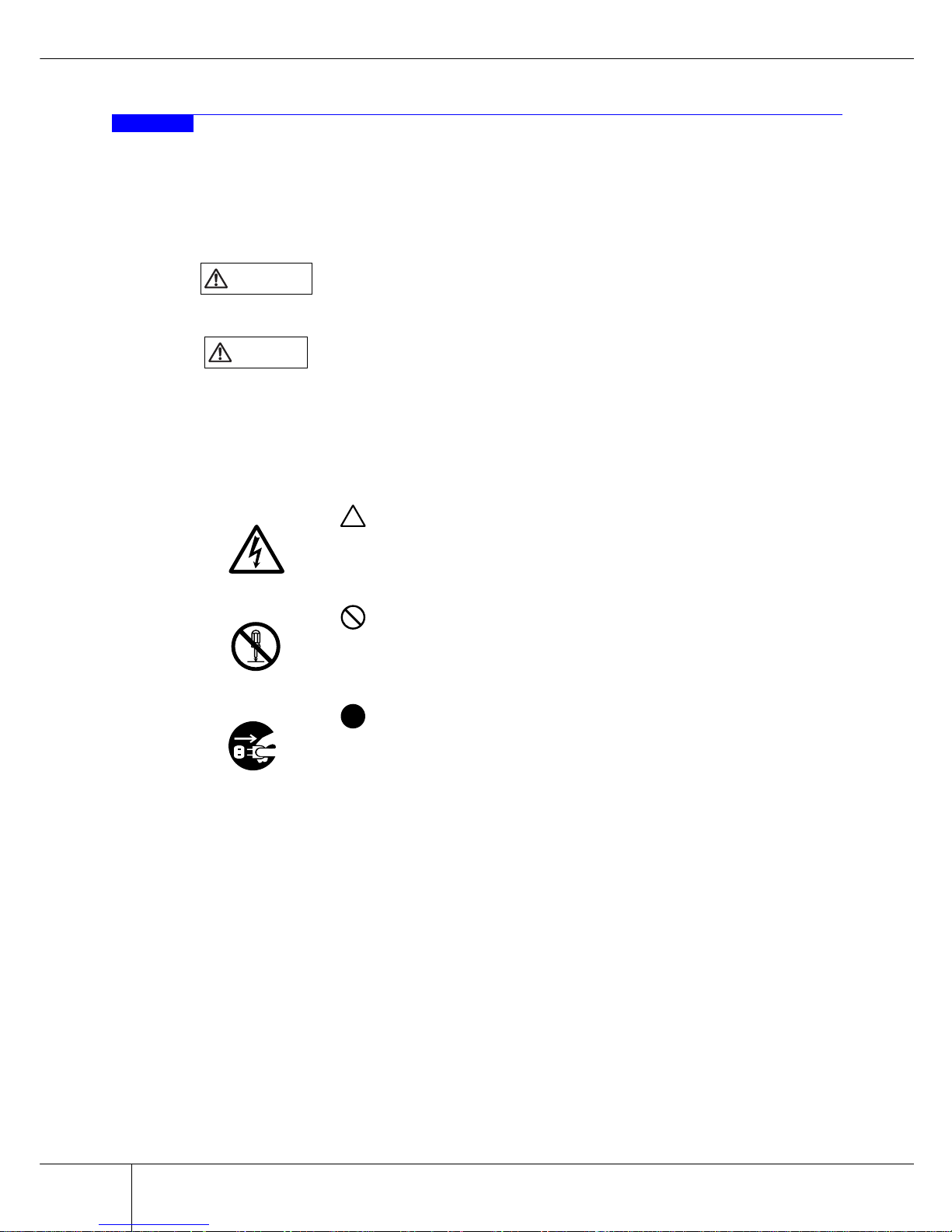
Warning Notations
Warning signs are shown throughout this manual in order to prevent injury to the user and/or material
damage. These signs are composed of a symbol and a message describing the recommended level of caution. The following explains the symbols, their levels of caution, and their meanings as used in this manual.
The following symbols are used to indicate the type of warnings or cautions being described.
WARNING
This symbol indicates the possibility of serious or fatal injury if the
ETERNUS2000 is not used properly.
CAUTIO
N
This symbol indicates the possibility of minor or moderate personal injury,
as well as damage to the ETERNUS2000 and/or to other users and their
property, if the ETERNUS2000 is not used properly.
I
MPORTAN
T
This symbol indicates IMPORTANT information for the user to note when
using the ETERNUS2000.
Electrical Shock
The triangle emphasizes the urgency of the WARNING and CAU-
TION contents. Inside the triangle and above it are details concerning the
symbol (e.g. Electrical Shock).
N
o Disassemb
ly
The barred "Do Not..." circle warns against certain actions. The
action which should be avoided is both illustrated inside the barred circle
and written above it (e.g. No Disassembly).
Unplu
g
The black "Must Do..." disk indicates actions that must be taken. The
required action is both illustrated inside the black disk and written above it
(e.g. Unplug).
Page 9
About this Manual
vii
P3AM-2512-03EN ETERNUS2000 disk storage system User Guide
Copyright 2009 FUJITSU LIMITED
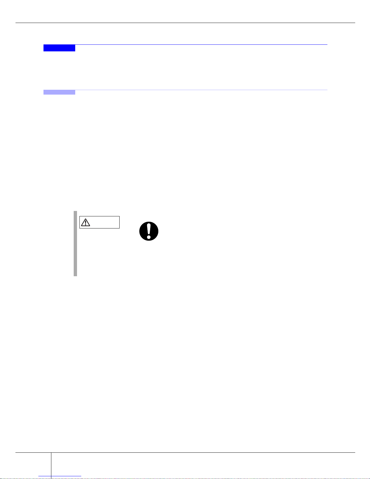
How Warnings are Presented in this Manual
A message is written beside the symbol indicating the caution level. This message is marked with a vertical
ribbon in the left margin, to distinguish this warning from ordinary descriptions.
An example is shown here.
Warning Level Indicator
Warning Type Indicator
Warning Details
To avoid damaging the ETERNUS2000, pay attention to the following
points when cleaning the ETERNUS2000:
- Make sure to disconnect the power when cleaning.
- Be careful that no liquid seeps into the ETERNUS2000 when using
cleaners, etc.
- Do not use alcohol or other solvents to clean the ETERNUS2000.
Warning Layout Ribbon
E
xample Warning
Page 10

Copyright 2009 FUJITSU LIMITED
viii
About this Manual
ETERNUS2000 disk storage system User Guide P3AM-2512-03EN
Additional Information
■ Expressions and abbreviations
The following are expressions and abbreviations used throughout this manual:
Note:
This notation indicates there is supplementary information in addition to the explanation already
provided.
Product names and abbreviations
• "Windows®" represents the following products.
- Microsoft® Windows® 2000 operating system
- Microsoft® Windows Server® 2003 operating system
- Microsoft® Windows Server® 2008 operating system
• "Solaris OS" represents a Solaris™ Operating System.
- "Solaris 8 OS" represents a Solaris™ 8 Operating System
- "Solaris 9 OS" represents a Solaris™ 9 Operating System
- "Solaris 10 OS" represents a Solaris™ 10 Operating System
Latest Information
The information in this document is subject to change without notice for functionality expansion of
ETERNUS2000 and improvement. The latest version of this document and the latest information about the
ETERNUS2000 is released in the following web-site. Access the following address if needed.
http://www.fujitsu.com/global/services/computing/storage/system/eternus2000/
Point
Functions and know how which can be useful when setting up or operating the ETERNUS2000.
Refer
This notation indicates related reference manuals.
Page 11

About this Manual
ix
P3AM-2512-03EN ETERNUS2000 disk storage system User Guide
Copyright 2009 FUJITSU LIMITED
Related Manuals
Refer to the following related manuals in addition to this manual.
Manuals Code Description
ETERNUS2000 models 100 and 200 disk storage
system Setup Guide (Fibre Channel type)
P3AM-2542
This manual describes
how to ready Fibre Channel type devices for operation.
ETERNUS2000 models 100 and 200 disk storage
system Setup Guide (iSCSI type)
P3AM-2552
This manual describes
how to ready iSCSI type
devices for operation.
ETERNUS2000 models 100 and 200 disk storage
system Setup Guide (SAS type)
P3AM-2562
This manual describes
how to ready SAS type
devices for operation.
ETERNUS2000 models 100 and 200 disk storage
system Safety Precautions
P3AM-1972
This manual describes the
points to note when installing and operating the
device.
ETERNUS2000 models 100 and 200 disk storage
system Package Contents
P3AM-1982
This is the list of package
contents for the device
and optional products.
ETERNUS2000 models 100 and 200 disk storage
system Using Optional Products
P3AM-1992
This manual describes the
points to note when using
optional products.
ETERNUS8000, ETERNUS4000, ETERNUS2000 disk storage system
Server Connection Guide (Fibre Channel)
(*1)
This manual describes
how to connect the
ETERNUS2000 (Fibre
Channel type) to a server.
For Solaris Operating System P3AM-1532
For HP-UX P3AM-1542
For AIX P3AM-1552
For Windows® P3AM-1562
For Linux P3AM-1572
For Fibre Channel Switch Settings P3AM-1582
For VMware® ESX P3AM-1592
ETERNUS8000, ETERNUS4000, ETERNUS2000
disk storage system
Server Connection Guide (iSCSI)
(*1)
P3AM-1672
This manual describes
how to connect the
ETERNUS2000 (iSCSI
type) to a server.
ETERNUS disk storage systems ETERNUSmgr Install Guide
This manual describes
how to install the
ETERNUSmgr.
For Solaris™ Operating System P2S0-0081
For Windows® P2WW-1631
For Linux P2U3-0021
For HP-UX P2S0-0092
For AIX P2S0-0102
ETERNUS disk storage systems ETERNUSmgr
User Guide -Introduction-
P2X0-0201
This manual describes the
outlines of basic operations for the
ETERNUSmgr.
Page 12
Copyright 2009 FUJITSU LIMITED
x
About this Manual
ETERNUS2000 disk storage system User Guide P3AM-2512-03EN
*1: Manuals are supplied in the product CD.
*2: Manuals are supplied in the ETERNUSmgr product CD.
*3: Online Help is also available.
ETERNUS2000 ETERNUSmgr User Guide
-Settings/Maintenance-
(*2)(*3)
P2X0-0620
This manual describes
how to monitor and set the
ETERNUS2000 with the
ETERNUSmgr.
ETERNUS Multipath Driver V2.0 User's Guide
This manual describes
how to use the optional
ETERNUS Multipath
Driver.
For Solaris™ Operating System P2S0-0061
(For Windows®) P2WW-1451
(For Linux) P2U3-0031
ETERNUS Multipath Driver V3.0 User's Guide
For Solaris™ Operating System P2S0-0062
ETERNUS MPIO for IBM AIX V2.0.1
Installation & Configuration Guide for AIX
P2U3-0150
Manuals Code Description
Page 13
xi
P3AM-2512-03EN ETERNUS2000 disk storage system User Guide
Copyright 2009 FUJITSU LIMITED
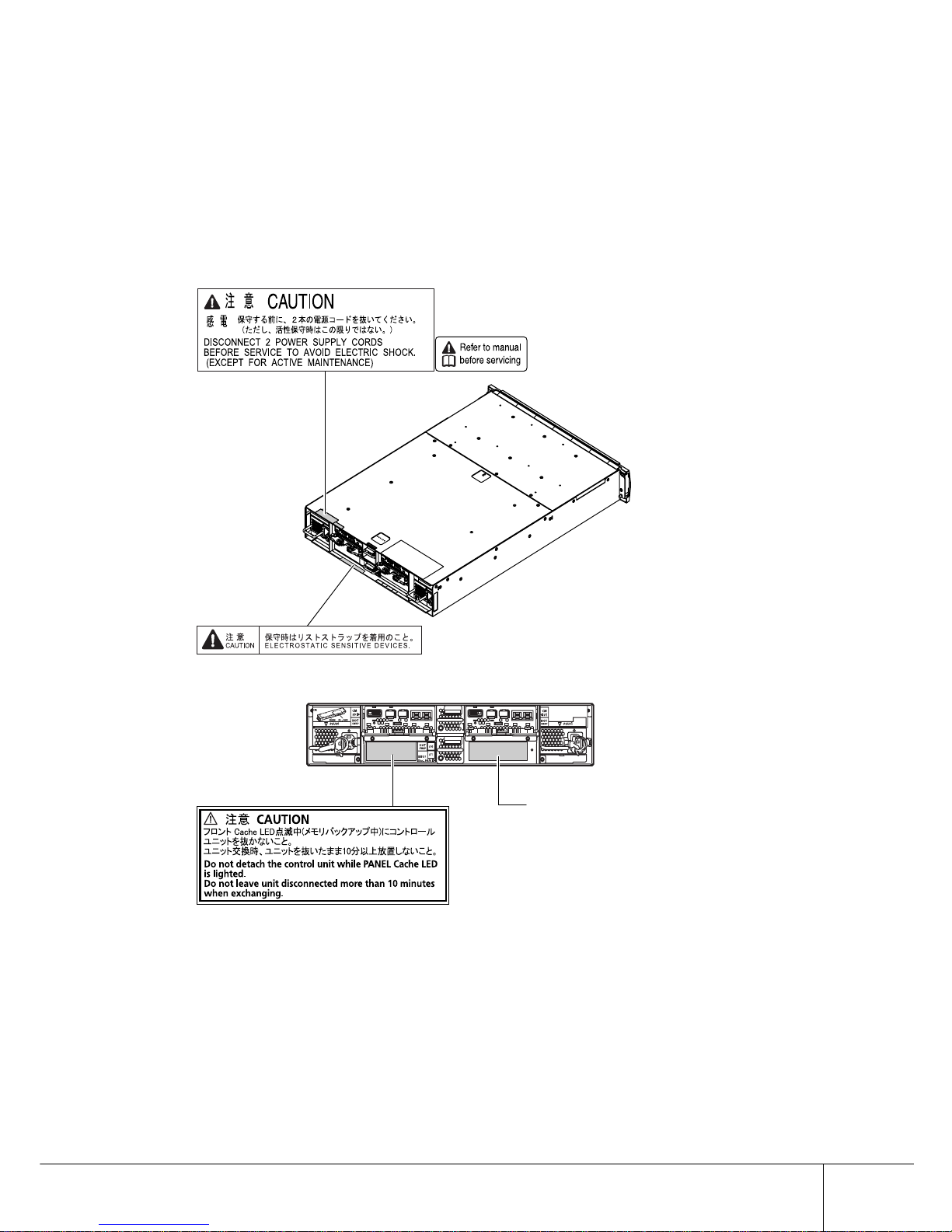
Labels
Warning labels and manufacturer's labels are found in various places of the ETERNUS2000, as shown in
the example below.
Do not remove these labels.
■ Controller Enclosure
Manufacturer’s label
The label with the model, serial #, etc.
is located here.
Page 14

Copyright 2009 FUJITSU LIMITED
xii
Labels
ETERNUS2000 disk storage system User Guide P3AM-2512-03EN
■ Drive Enclosure
Page 15

Labels
xiii
P3AM-2512-03EN ETERNUS2000 disk storage system User Guide
Copyright 2009 FUJITSU LIMITED
■ AC Outlet Box
For 1U
For 4U
Manufacturer’s label
The label with the model, serial #, etc.
is located here.
Manufacturer’s label
The label with the model, serial #, etc.
is located here.
Page 16

Copyright 2009 FUJITSU LIMITED
xiv
Labels
ETERNUS2000 disk storage system User Guide P3AM-2512-03EN
This page is intentionally left blank.
Page 17

xv
P3AM-2512-03EN ETERNUS2000 disk storage system User Guide
Copyright 2009 FUJITSU LIMITED
1
2
3
4
5
6
A
B
Contents
Chapter 1 Overview .................................................................1
1.1 System Features ...........................................................................1
1.2 Configuration .................................................................................4
1.2.1 RAID Level ........................................................................................................................4
1.2.2 RAID Groups and Volumes ...............................................................................................8
1.2.3 System Disks ..................................................................................................................10
1.2.4 Hot Spare Disks ..............................................................................................................11
1.2.5 Disk Drives ......................................................................................................................11
1.2.6 Host Interface ..................................................................................................................12
1.3 Functions .....................................................................................13
1.3.1 Rebuild/Copyback ...........................................................................................................13
1.3.2 Redundant Copy .............................................................................................................15
1.3.3 Advanced Copy ...............................................................................................................16
1.3.4 RAID Migration ................................................................................................................17
1.3.5 Logical Device Expansion (LDE) .....................................................................................19
1.3.6 LUN Concatenation .........................................................................................................20
1.3.7 Security Functions ...........................................................................................................21
1.3.8 ECO mode ......................................................................................................................23
Chapter 2 Hardware...............................................................25
2.1 Components ................................................................................25
2.1.1 Controller Enclosure ........................................................................................................25
2.1.2 Drive Enclosure ...............................................................................................................32
2.1.3 AC outlet box ...................................................................................................................36
2.2 Standard Operations ...................................................................37
2.2.1 Power ON Control ...........................................................................................................37
2.2.2 Power OFF Control .........................................................................................................39
2.2.3 Attaching and Removing the Front Cover .......................................................................40
2.3 Flow from Installation to Operation ..............................................42
Chapter 3 Installation ............................................................45
3.1 Preparation ..................................................................................45
3.1.1 Placement Area ...............................................................................................................45
3.1.2 Check the number of wall outlets ....................................................................................46
3.2 Rack Installation ..........................................................................48
3.2.1 Installing Controller Enclosure ........................................................................................49
3.2.2 Installing Drive Enclosure ................................................................................................52
3.2.3 Installing AC Outlet Box ..................................................................................................55
Page 18

Copyright 2009 FUJITSU LIMITED
xvi
Contents
ETERNUS2000 disk storage system User Guide P3AM-2512-03EN
Chapter 4 Setup .....................................................................59
4.1 Prior Preparation .........................................................................59
4.2 Cable Connection ........................................................................62
4.2.1 LAN Cable Connection (Twist Pair Cable Compatible with Category 5)
(for Operation Management) ..........................................................................................62
4.2.2 Fibre Channel Cable Connection (Fibre Channel Type) .................................................65
4.2.3 LAN Cable Connection (Twisted Pair Cable Compatible with Enhanced Category 5)
(iSCSI Type) ....................................................................................................................67
4.2.4 MiniSAS Cable Connection (SAS Type) .........................................................................69
4.2.5 MiniSAS Cable Connection (For Drive Enclosures) ........................................................71
4.2.6 Power Cord Connection ..................................................................................................76
4.3 ETERNUS2000 Setup .................................................................87
4.3.1 Basic setup ......................................................................................................................89
4.3.2 Advanced Copy Setup ..................................................................................................103
4.3.3 AC Automatic Linkage Mode Setup ..............................................................................106
4.4 Installing and Setting up ETERNUSmgr ....................................107
4.5 Maintenance Setup ....................................................................108
4.5.1 Setting up the ETERNUS2000 monitoring ....................................................................108
4.5.2 Remote Support Setup ..................................................................................................112
4.6 Setting up the Server Connection ..............................................115
4.7 System Status Check ................................................................116
Chapter 5 Installing Optional Products .............................119
5.1 Disk Drive Installation ................................................................119
5.1.1 Disk Drive Handling Instructions ...................................................................................119
5.1.2 Installable Disk Drives ...................................................................................................120
5.1.3 Disk Drive Installation Positions ....................................................................................121
5.1.4 Additional Disk Drive Installation Procedure .................................................................121
5.2 Drive Enclosure Installation .......................................................127
5.2.1 Drive Enclosure Handling Instructions ..........................................................................127
5.2.2 Installable Drive Enclosures ..........................................................................................128
5.2.3 Drive Enclosure Rack Mounting Procedure ..................................................................128
5.2.4 Additional Drive Enclosure Installation ..........................................................................131
5.3 Battery Unit Installation ..............................................................139
5.3.1 Battery Unit Handling Instructions .................................................................................139
5.3.2 Installable Battery Unit ..................................................................................................140
5.3.3 Battery Unit Installation Position ...................................................................................140
5.3.4 Additional Battery Unit Installation Procedure ...............................................................140
Chapter 6 Operation and Troubleshooting .......................147
6.1 Checking the ETERNUS2000 Status ........................................147
6.2 Backing up Data ........................................................................147
Page 19

Contents
xvii
P3AM-2512-03EN ETERNUS2000 disk storage system User Guide
Copyright 2009 FUJITSU LIMITED
6.3 Maintenance Service .................................................................148
6.3.1 Maintenance Support Period .........................................................................................148
6.3.2 Periodical Component Replacement .............................................................................148
6.4 Post Start-of-Operation Changes to the Configuration ..............150
6.4.1 When Replacing the Fibre Channel Card .....................................................................150
6.4.2 When Replacing the LAN Card / iSCSI HBA ................................................................151
6.4.3 When Replacing the SAS Card .....................................................................................151
6.5 Troubleshooting .........................................................................153
6.5.1 Check List .....................................................................................................................153
6.5.2 Trouble Record .............................................................................................................158
Appendix A Specifications.....................................................161
A.1 Base Device Specifications ........................................................161
A.1.1 ETERNUS2000 model 100 specification ...................................................................... 161
A.1.2 ETERNUS2000 model 200 specification ...................................................................... 165
A.2 Optional Products Specification..................................................168
A.2.1 Disk Drive...................................................................................................................... 168
A.2.2 Drive Enclosure............................................................................................................. 171
A.2.3 Additional Battery Unit Option....................................................................................... 171
A.2.4 AC Outlet Box ............................................................................................................... 172
Appendix B Events detected by ServerView........................173
Index ....................................................................................175
Page 20

Copyright 2009 FUJITSU LIMITED
xviii
Contents
ETERNUS2000 disk storage system User Guide P3AM-2512-03EN
This page is intentionally left blank.
Page 21

xix
P3AM-2512-03EN ETERNUS2000 disk storage system User Guide
Copyright 2009 FUJITSU LIMITED
Figure of Contents
Figure 1.1 RAID0 Concept ................................................................................................................. 5
Figure 1.2 RAID1 Concept ................................................................................................................. 5
Figure 1.3 RAID1+0 Concept ............................................................................................................. 6
Figure 1.4 RAID5 Concept ................................................................................................................. 6
Figure 1.5 RAID6 Concept ................................................................................................................. 7
Figure 1.6 Example of a RAID group ................................................................................................. 8
Figure 1.7 RAID group concept.......................................................................................................... 9
Figure 1.8 System disk and user disk .............................................................................................. 10
Figure 1.9 Hot Spare Disks .............................................................................................................. 11
Figure 1.10 Rebuild/Copyback function ............................................................................................. 13
Figure 1.11 Redundant Copy Function .............................................................................................. 15
Figure 1.12 Example for use Advanced Copy function ...................................................................... 16
Figure 1.13 Example for use RAID Migration 1.................................................................................. 18
Figure 1.14 Example for use RAID Migration 2.................................................................................. 18
Figure 1.15 Example for use Logical Device Expansion .................................................................... 19
Figure 1.16 Example for use LUN Concatenation.............................................................................. 20
Figure 1.17 LUN Mapping function..................................................................................................... 21
Figure 1.18 Host Affinity function ....................................................................................................... 22
Figure 1.19 Setting example for ECO mode schedule ....................................................................... 23
Figure 2.1 Front view of controller enclosure (with front cover) ....................................................... 25
Figure 2.2 Front view of controller enclosure (without front cover) .................................................. 26
Figure 2.3 Disk drive slot numbers (controller enclosure)................................................................ 26
Figure 2.4 Rear view of controller enclosure.................................................................................... 27
Figure 2.5 Fibre Channel type controller (rear view closeup)........................................................... 27
Figure 2.6 iSCSI type controller (rear view closeup)........................................................................ 28
Figure 2.7 SAS type controller (rear view closeup).......................................................................... 29
Figure 2.8 Other controller LEDs (rear view closeup) ...................................................................... 30
Figure 2.9 Front view of drive enclosure (with front cover) .............................................................. 32
Figure 2.10 Front view of drive enclosure (without front cover) ......................................................... 33
Figure 2.11 Slot number of disk drives (drive enclosure)................................................................... 33
Figure 2.12 Rear view of drive enclosure........................................................................................... 34
Figure 2.13 Expander (Closeup) ........................................................................................................ 34
Figure 2.14 LEDs in the rear side of the controller enclosure ............................................................ 35
Figure 2.15 AC outlet box (1U)........................................................................................................... 36
Figure 2.16 AC outlet box (4U)........................................................................................................... 36
Figure 4.1 MiniSAS cable connection
(between the Controller Enclosure and Drive Enclosure) ............................................... 74
Figure 4.2 MiniSAS cable connection
(When two or more Drive Enclosures are added) ........................................................... 75
Figure 4.3 Connection of AC output cables (1U).............................................................................. 80
Figure 4.4 Connection of AC output cables (4U).............................................................................. 84
Figure 4.5 Network Settings label .................................................................................................... 87
Figure 4.6 Tutorial wizard [GUIDE] screen....................................................................................... 89
Figure 4.7 Network environment setting screen............................................................................... 90
Figure 4.8 Date and time setting screen .......................................................................................... 91
Figure 4.9 Port settings (topology settings) screen (for Fibre Channel)........................................... 92
Figure 4.10 Port settings screen (for iSCSI type)............................................................................... 93
Figure 4.11 Port settings screen (for SAS)......................................................................................... 94
Figure 4.12 Hot Spare disk registration screen.................................................................................. 96
Figure 4.13 RAID group registration screen....................................................................................... 98
Figure 4.14 Volume creation screen ................................................................................................ 100
Figure 4.15 Volume creation confirmation screen............................................................................ 100
Page 22

Copyright 2009 FUJITSU LIMITED
xx
Figure of Contents
ETERNUS2000 disk storage system User Guide P3AM-2512-03EN
Figure 4.16 Assignment of volumes to the Host Affinity group screen............................................. 101
Figure 4.17 Host LUN number setting screen.................................................................................. 102
Figure 4.18 Host Affinity group setting confirmation screen............................................................. 103
Figure 4.19 License registration screen ........................................................................................... 104
Figure 4.20 Network environment settings screen (when the ServerView is used) ......................... 109
Figure 4.21 SNMP agent screen (Trap Destination screen) ............................................................ 109
Figure 4.22 MIB definition extraction for ServerView monitoring screen.......................................... 110
Figure 4.23 SNMP Trap test screen example .................................................................................. 111
Figure 4.24 General status lamp...................................................................................................... 116
Figure 4.25 RAID group list screen .................................................................................................. 117
Figure 4.26 Volume list screen......................................................................................................... 117
Figure 5.1 Position of disk drive slots............................................................................................. 121
Figure 5.2 Position of Battery Unit.................................................................................................. 140
Figure 6.1 Battery unit status display window ................................................................................ 149
Figure 6.2 Battery unit expansion failure screen............................................................................ 155
Figure 6.3 ETERNUS Multipath Manager Window ........................................................................ 156
Figure 6.4 Trouble record (1/2) ...................................................................................................... 158
Figure 6.5 Trouble record (2/2) ...................................................................................................... 159
Page 23

xxi
P3AM-2512-03EN ETERNUS2000 disk storage system User Guide
Copyright 2009 FUJITSU LIMITED
Table of Contents
Table 1.1 User Capacity for each RAID Level .................................................................................. 7
Table 1.2 User Capacity for each RAID Level .................................................................................. 8
Table 1.3 Recommended number of disk drives per RAID group..................................................... 9
Table 1.4 The maximum number of volumes that can be set ........................................................... 9
Table 1.5 Volume formatting time ................................................................................................... 10
Table 1.6 Rebuild process times (for 100GB volumes)................................................................... 14
Table 1.7 Copyback process times (for 100GB volumes) ............................................................... 14
Table 3.1 Wall outlets and cable lengths ........................................................................................ 46
Table 3.2 Required number of Power Outlets (ETERNUS2000 model 100) .................................. 46
Table 3.3 Required number of power outlets
(ETERNUS2000 model 200 when AC outlet boxes are not connected) ......................... 47
Table 3.4 Required number of power outlets
(ETERNUS2000 model 200 when AC outlet boxes are connected) ............................... 47
Table 4.1 Connection path of a power cord (AC output cable) (AC outlet box (1U)) ...................... 79
Table 4.2 Connection path of a power cord (AC output cable) (AC outlet box (4U)) ...................... 83
Table 4.3 Network Settings label fields........................................................................................... 87
Table A.1 Specification (ETERNUS2000 model 100 Fibre Channel type) .................................... 161
Table A.2 Specification (ETERNUS2000 model 100 iSCSI type) ................................................. 162
Table A.3 Specification (ETERNUS2000 model 100 SAS type) ................................................... 163
Table A.4 Specification (ETERNUS2000 model 200 Fibre Channel type) .................................... 165
Table A.5 Specification (ETERNUS2000 model 200 iSCSI type) ................................................. 166
Table A.6 Specification (ETERNUS2000 model 200 SAS type) ................................................... 167
Table A.7 Disk drive specification (146GB/15krpm SAS disk drive).............................................. 168
Table A.8 Disk drive specification (300GB/15krpm SAS disk drive).............................................. 168
Table A.9 Disk drive specification (450GB/15krpm SAS disk drive).............................................. 169
Table A.10 Disk drive specification (400GB/10krpm SAS disk drive).............................................. 169
Table A.11 Disk drive specification (500GB/7.2krpm Nearline SAS disk drive) .............................. 169
Table A.12 Disk drive specification (750GB/7.2krpm Nearline SAS disk drive) .............................. 170
Table A.13 Disk drive specification (1TB/7.2krpm Nearline SAS disk drive)................................... 170
Table A.14 Drive Enclosure specification ........................................................................................ 171
Table A.15 AC outlet box (1U) specification.................................................................................... 172
Table A.16 AC outlet box (4U) specification.................................................................................... 172
Table B.1 ServerView event list..................................................................................................... 173
Page 24

Copyright 2009 FUJITSU LIMITED
xxii
Table of Contents
ETERNUS2000 disk storage system User Guide P3AM-2512-03EN
This page is intentionally left blank.
Page 25

1
P3AM-2512-03EN ETERNUS2000 disk storage system User Guide
Copyright 2009 FUJITSU LIMITED
1
Chapter 1
Overview
This chapter provides an overview of the ETERNUS2000 features, and specifications.
1.1 System Features
Special features of the ETERNUS2000 are shown below:
■ Space and Energy Savings
• Compact design to make effective use of rack space
• There are two models available; ETERNUS2000 model 100 and ETERNUS2000 model
200. Both models are designed to be 2U size at the minimum
(*1)
. Up to 12 disk drives and
up to 12TB disk capacity
(*2)
can be installed.
•2U
(*1)
of drive enclosure can be expanded in the ETERNUS2000 models 100 and 200.
ETERNUS2000 model 200 allows up to 120 disk drives and 120TB as the disk capacity
(*2)
.
*1: 2U indicates the device height that can be installed in two units of 19-inch rack (88mm).
*2: Physical capacity is calculated based on the assumption 1,000GB = 1TB (including Hot Spare Disks).
• Energy savings by the latest technology
Using the latest 1-chip RAID controller that is configured by multiple chips and reducing number of
components allows energy savings.
• ECO mode to reduce environmental load
Using the ECO mode function to start and stop the spindle rotation in the disk drive for each RAID
group during the specified hour. Stop the spindle rotation when there is no access to the disk drive to
reduce power consumption and decreases environmental load.
■ Easy Installation
• Easy setup
The ETERNUS2000 can be configured easily using a web browser. When installing the
ETERNUS2000, follow the setup wizard and just input parameters for displayed setting items to create
RAID groups and volumes, and assign to the server.
Page 26

Copyright 2009 FUJITSU LIMITED
2
1.1 System Features
ETERNUS2000 disk storage system User Guide P3AM-2512-03EN
■ High scalability and versatile connectivity
• Utilizes the latest disk technology
ETERNUS2000 utilizes the SAS disk drives
(*1)
(450GB/300GB/146GB (15,000rpm), 400GB
(10,000rpm)).
Also, ETERNUS2000 supports large capacity / cost effective Nearline SAS disk drives
(*1)
(1TB/
750GB/500GB (7,200rpm)) for data backup and archiving.
*1: SAS: Serial Attached SCSI
• Supports capacity expansion during system operation
• Disk drives and drive enclosures can be added during the system operation.
• RAID group capacity can be expanded by adding disk drive from the unit of one.
• Volume can be expanded during the system operation. Even when the work load
increased rapidly, ETERNUS2000 flexibly expand the volume capacity with no interruption of the operation.
• High connectivity supports the multi-platform environment
• ETERNUS2000 supports FC-SAN, IP-SAN, or DAS environment by utilizing the Fibre
Channel interface (maximum transfer speed: 4Gbps), iSCSI interface (maximum transfer
speed: 1Gbps), or SAS interface (maximum transfer speed: 3Gbps) as the host interface.
• ETERNUS2000 supports multiple Operating Systems such as UNIX, Linux, and Windows®, and can be connected as a storage system for PRIMEQUEST, SPARC Enterprise, and PRIMERGY servers as well as for UNIX/IA servers of other companies. Also
the RAID aggregation using SAN (Storage Area Network) is available.
■ Data integrity with high-speed backup
• Nearline SAS disk drives for data backup and archiving
• Using large capacity / cost effective Nearline SAS disk drives allows low cost D2D (Disk to
Disk) backup and high-speed recovery in the case of unexpected failure.
• Storing the less frequently accessed data such as archive data in the Nearline SAS disk
drives allows easy reading. Nearline SAS disk drives and SAS disk drives can be installed
in the same drive enclosure.
• Various backup function
Cooperation between the Advanced Copy function for ETERNUS2000 models 100 and 200
(Optional), and the high-speed backup replication software "ETERNUS SF AdvancedCopy Manager"
allows OPC (One Point Copy), the high-speed copying of disk volumes at specified times.
Page 27

Chapter 1 Overview
3
P3AM-2512-03EN ETERNUS2000 disk storage system User Guide
Copyright 2009 FUJITSU LIMITED
1
■ High reliability supports 24/7/365 operation
• Duplication of important components
Important components such as controllers, power supply units, and fans are duplicated to continue the
operation in the case of unexpected failure. Also this allows the hot swapping of failed components
with the device power on. In addition, the latest firmware can be applied during system operation.
• RAID6 responds to the double failure of disk drives
ETERNUS2000 supports RAID6, using two parity disks in one RAID group. RAID6 ensures the data
safety in the unlikely case of a fatal second malfunction within a single RAID group. Also the
ETERNUS2000 supports RAID1, RAID1+0, and RAID5 to realize the flexible RAID configuration.
• Redundant copy ensures disk drive redundancy
ETERNUS2000 diagnoses the disk drives to detect the failure prediction. When the disk drive requires
preventive maintenance, ETERNUS2000 automatically copies the data in the target disk drive to
ensure data redundancy.
• Block Guard ensures data integrity
ETERNUS2000 adds check codes and check them at multiple checkpoints on data transfer path to
ensure the data integrity.
Page 28
Copyright 2009 FUJITSU LIMITED
4
1.2 Configuration
ETERNUS2000 disk storage system User Guide P3AM-2512-03EN
1.2 Configuration
This chapter describes items to be noted before configuring the ETERNUS2000 systems.
1.2.1 RAID Level
This section describes the supported RAID level and usage (RAID level selection criteria), and RAID
group configuration.
■ Supported RAID levels and mechanism
ETERNUS2000 supports the following RAID levels.
• RAID0 (striping)
• RAID1 (mirroring)
• RAID1+0 (striping of pairs of disks for mirroring)
• RAID5 (striping with distributed parity blocks)
• RAID6 (striping with distributed double parity blocks) (*1)
*1: RAID6 ensures data safety and continues system operation in the case of a second malfunction within a
single RAID group. RAID6 redundancy allows high availability system operation.
Each RAID level description is shown below.
CAUTIO
N
Do
Remember that a RAID0 configuration is not redundant. This means that if
a RAID0 disk drive fails, the data will not be recoverable.
Therefore, using RAID1, RAID1+0, RAID5, or RAID6 configuration is recommended.
Page 29
Chapter 1 Overview
5
P3AM-2512-03EN ETERNUS2000 disk storage system User Guide
Copyright 2009 FUJITSU LIMITED
1
• RAID0 (striping)
Data is split in unit of blocks and stored across multiple disks.
Figure 1.1 RAID0 Concept
• RAID1 (mirroring)
RAID1 stores the same data on two duplicated disks at the same time.
If one disk drive fails, other disk drive continues operation.
Figure 1.2 RAID1 Concept
A
C
B
D
Data writing request
Data is stored in multiple disks.
HDD0 HDD1
ABCD
A
B
C
D
ABCD
Data writing request
A
B
C
D
Data is stored on two disks at the same time.
HDD0 HDD1
Page 30

Copyright 2009 FUJITSU LIMITED
6
1.2 Configuration
ETERNUS2000 disk storage system User Guide P3AM-2512-03EN
• RAID1+0 (striping of pairs of disks for mirroring)
RAID1+0 combines the performance of RAID0 (striping) with the reliability of RAID1 (mirroring).
Figure 1.3 RAID1+0 Concept
• RAID5 (striping with distributed parity)
Data is allocated in units of blocks across multiple disks to duplicate data.
Figure 1.4 RAID5 Concept
HDD3
HDD7
D
D’
HDD2
HDD6
C
C’
HDD1
HDD5
B
B’
HDD0
HDD4
A
A’
Striping (RAID0)
Mirroring (RAID1)
Data writing request
ABCD
Mirroring
Mirroring
Mirroring
Mirroring
A
E
I
M
ABCD
Data writing request
B
F
J
P
M, N, O, P
C
G
P
I, J, K, L
N
D
P
E, F, G, H
K
O
H
L
P
Create Parity Data
P
A, B, C, D
A B DC
HDD0 HDD1 HDD2 HDD3 HDD4
Paruty for data A to D
Paruty for data E to H
Paruty for data I to L:
Paruty for data M to P
Parity M, N, O, P
Parity I, J, K, L
Parity E, F, G, H
Parity A, B, C, D
Page 31

Chapter 1 Overview
7
P3AM-2512-03EN ETERNUS2000 disk storage system User Guide
Copyright 2009 FUJITSU LIMITED
1
• RAID6 (striping with distributed double parities)
Store two different parities on different disk drives (double parities) to recover from up to two disk
drive failures.
Figure 1.5 RAID6 Concept
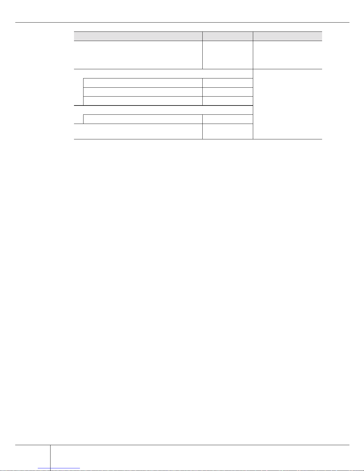
■ User Capacity for each RAID Level
User capacity varies according to the RAID level.
Table 1.1 shows the formula for user capacity computation.
Table 1.1 User Capacity for each RAID Level
1. Actual number of disk drives can be installed depend on the ETERNUS2000 models.
P2
M, N, O, P
P2
I, J, K, L
A
E
I
M
ABCD
Data writing request
B
F
J
P1
M, N, O, P
C
G
P1
I, J, K, L
D
P1
E, F, G, H
P2
E, F, G, H
N
K
O
P1
A, B, C, D
H
L
P
P2
A, B, C, D
A B DC
Create parity data
HDD0 HDD1 HDD2 HDD3 HDD4 HDD5
Parity for data A to D: Parity1
A, B, C, D and Parity2 A, B, C, D
Parity for data E to H: Parity1 E, F, G, H and Parity2 E, F, G, H
Parity for data I to L: Parity1 I, J, K, L and Parity2 I, J, K, L
Parity for data M to P: Parity1 M, N, O, P and Parity2 M, N, O, P
RAID level Number of disk drives (*1) Formula for user capacity computation
RAID0 2 to 16 Disk drive capacity x Number of disk drives
RAID1 2 Disk drive capacity x Number of disk drives/2
RAID1+0 4 to 32 Disk drive capacity x Number of disk drives/2
RAID5 3 to 16
Disk drive capacity x
(Number of disk drives - 1)
RAID6 5 to 16
Disk drive capacity x
(Number of disk drives - 2)
Page 32

Copyright 2009 FUJITSU LIMITED
8
1.2 Configuration
ETERNUS2000 disk storage system User Guide P3AM-2512-03EN
■ Reliability, performance, capacity for each RAID level
Table 1.2 shows the comparison result of reliability, performance, capacity for each RAID level.
Table 1.2 User Capacity for each RAID Level
■ Recommended RAID level
Select the appropriate RAID level according to the usage.
• Recommended RAID level is RAID1, RAID1+0, RAID5 and RAID6.
• For read and write performance, RAID1+0 configuration is recommended.
• For read only file servers and backup servers, RAID5 or RAID6 can also be used. However, if the disk drive fails, note that it may affect the operation I/O for a rebuilding (writing)
operation.
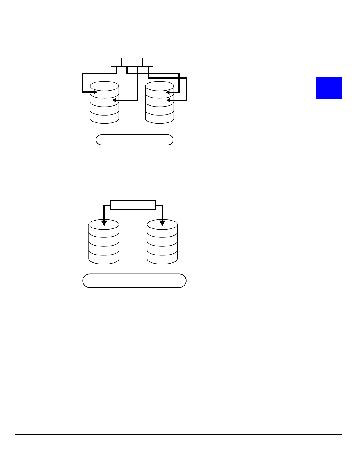
1.2.2 RAID Groups and Volumes
■ RAID group
In an ETERNUS2000 disk storage system, you can setup the RAID groups to all use the same RAID level
or a mixture of different RAID levels.
Figure 1.6 Example of a RAID group
RAID level Reliability Performance
(Writing speed)
Capacity
RAID0 Bad Good Very Good
RAID1 Very Good Good Not Bad
RAID1+0 Very Good Good Not Bad
RAID5 Good Not Bad Good
RAID6 Very Good Not Bad Good
RAID Group 1
RAID Group 2
Page 33

Chapter 1 Overview
9
P3AM-2512-03EN ETERNUS2000 disk storage system User Guide
Copyright 2009 FUJITSU LIMITED
1
Table 1.3 show the recommended number of disk drives that configures a RAID group.
Table 1.3 Recommended number of disk drives per RAID group
Note:
• Adding more disk drives to a RAID group improves performance.
• Use of higher capacity disk drives in a RAID group will increase the time required for
the drive rebuild process to complete.
• Similarly, the more disk drives per RAID5 or RAID6 group, the longer the drive rebuild
process will take following a disk drive failure.
■ Volume
Logical disk drive areas in RAID groups are called volumes.
A volume is the basic RAID unit, that can be recognized by the server.
Figure 1.7 RAID group concept
• Table 1.4
shows the maximum number of volumes that can be set.
Table 1.4 The maximum number of volumes that can be set
RAID level Recommended number of disk drives
RAID1 2
RAID1+0 4, 6, 8, 10
RAID5 3, 4, 5, 6
RAID6 5, 6, 7
Model Per RAID group Per storage system
model 100 Max. 128 Max. 512
model 200 Max. 128 Max. 1,024
RAID Group 1 RAID Group 2
Volume 1
Volume 2
Volume 3
Page 34

Copyright 2009 FUJITSU LIMITED
10
1.2 Configuration
ETERNUS2000 disk storage system User Guide P3AM-2512-03EN
• Table 1.5 shows the time for volume formatting.
Table 1.5 Volume formatting time
*1: The value shows the time required for volume formatting when there is no server I/O. The time depends
on the disk drive configuration or the disk type.
*2: 15,000rpm
• No more than 8TB can be used for any one volume. However, the maximum allowed volume capacity is OS dependent.
1.2.3 System Disks
System disks are disk drives which have part of their area (the system area) assigned for use by the firmware.
Figure 1.8 System disk and user disk
Two system disks are installed in Slot0 and Slot1 in the controller enclosure.
The location of system disks can be confirmed by the setting/maintenance program.
RAID level No. of disk drives
Time required for volume formatting (*1)
SAS disk drives (*2) Nearline SAS disk drives
RAID1 2 Approx. 30 minutes/100GB Approx. 85 minutes/100GB
RAID1+0 8 Approx. 20 minutes/100GB Approx. 50 minutes/100GB
RAID5 5 Approx. 20 minutes/100GB Approx. 50 minutes/100GB
RAID6 6 Approx. 25 minutes/100GB Approx. 70 minutes/100GB
I
MPORTAN
T
System disks cannot be registered as hot spare disks because their
user capacity is smaller than other disk drives (user disks).
System
User
User
System Disk User Disk
Page 35

Chapter 1 Overview
11
P3AM-2512-03EN ETERNUS2000 disk storage system User Guide
Copyright 2009 FUJITSU LIMITED
1
1.2.4 Hot Spare Disks
Hot spare disks are used as the spare disk drives when the disk drives in the RAID group have failed, or are
in error status.
Make sure to register the hot spare disk. If the hot spare disk has been registered, when one of the disk
drives in the RAID group has a problem, data from this drive is automatically repaired into the hot spare
disk.
Figure 1.9 Hot Spare Disks
1.2.5 Disk Drives
Two kinds of disk drive can be installed in the device: SAS disk drives and Nearline SAS disk drives. Each
disk drive are suitable for the following usages.
• SAS Disk Drive
SAS disk drives are highly-performance/high-reliability disk drives for enterprise use. SAS disk
drives support 24/7/365 operations and are used to store frequently accessed data such as high performance databases.
• Nearline SAS Disk Drive
Nearline SAS disk drives are high capacity / cost effective disk drives for data backup and archive
use. Nearline SAS disk drives can store information that requires a lower access rate at a still reasonable speed more cost effectively than the SAS disk drives.
CAUTIO
N
Do
• If a disk drive configured in a RAID1, RAID1+0, RAID5, or RAID6 group
fails, contact your maintenance engineer immediately as the failed disk
drive should be replaced at once. If another disk drive fails before the
first disk drive that failed is replaced, the data of the second disk drive
may be lost.
• Disk drives in Slot#0 – Slot#3 of controller enclosure (system disks)
cannot be registered as a hot spare disk.
I
MPORTAN
T
System disks cannot be registered as hot spare disks.
User Disk User Disk User Disk Hot Spare Disk
Failure
Page 36

Copyright 2009 FUJITSU LIMITED
12
1.2 Configuration
ETERNUS2000 disk storage system User Guide P3AM-2512-03EN
1.2.6 Host Interface
ETERNUS2000 is available in three types: a Fibre Channel type with Fibre Channel host interfaces, an
iSCSI type with iSCSI host interfaces, and a SAS type with SAS host interfaces.
• Fibre Channel interface
Fibre Channel supports two connection topologies, Arbitrated Loop and Fabric.
Maximum transfer speed is 4Gbps.
This interface is used for database servers, for the expandability and performance benefits it provides.
• iSCSI interface
iSCSI is the protocol that sends and receives SCSI commands to IP packets on Ethernet.
Maximum transfer speed is 1Gbps.
This interface is used for a section in large companies, or for small and medium companies, since
this interface can be introduced at a lower cost than Fibre Channel interface.
To ensure efficient iSCSI performance, we recommend that networks used for general purposes,
such as accessing the Internet or transferring files, and networks used for iSCSI be physically separated.
• SAS interface
The SAS (Serial Attached SCSI) interface uses serial rather than parallel data transfers in order to
provide improved performance, while still maintaining the high reliability of conventional SCSI.
With this interface the server is attached via a DAS (Direct Attached Storage) connection. Because
DAS connections are less scalable than SAN connections, it is recommended that use of this interface be restricted to smaller-scale systems.
Maximum transfer speed is 3Gbps.
Page 37

Chapter 1 Overview
13
P3AM-2512-03EN ETERNUS2000 disk storage system User Guide
Copyright 2009 FUJITSU LIMITED
1
1.3 Functions
This section describes the main ETERNUS2000 functions.
1.3.1 Rebuild/Copyback
When a disk drive fails and the RAID group redundancy has been broken, Rebuild/Copyback restores the
disk drive status back to normal status as a background process.
Figure 1.10 Rebuild/Copyback function
Hot Spare Disk
Hot Spare Disk
Creates data from the other disk drive than
failed disk drive and writes the data into
the hot spare disk.
After replaceing completed,
copies the data from the hot spare disk
to new disk drive.
Replaces the failed disk drive with the new disk drive.
Failure
Rebuild
Copyback
RAID5 (Redundant)
RAID5 (No Redundancy)
RAID5 (Redundant)
RAID5 (Redundant)
Page 38

Copyright 2009 FUJITSU LIMITED
14
1.3 Functions
ETERNUS2000 disk storage system User Guide P3AM-2512-03EN
Table 1.6 shows the times required for the rebuild process to complete for various disk configurations.
Table 1.6 Rebuild process times (for 100GB volumes)
*1: The time required to rebuild a 100GB volume of the indicated RAID level, number and type of disk drives when
there is no concurrent server I/O.
*2: 15,000rpm
Table 1.7 shows the times required for the copyback process to complete for various disk configurations.
Table 1.7 Copyback process times (for 100GB volumes)
*1: The time required to copyback a 100GB volume of the indicated RAID level, number and type of disk drives
when there is no concurrent server I/O.
*2: 15,000rpm
RAID level No. of disk drives
Rebuild process time (*1)
SAS disk drives (*2) Nearline SAS disk drives
RAID1 2 Approx. 20 minutes Approx. 60 minutes
RAID1+0 8 Approx. 5 minutes Approx. 15 minutes
RAID5 5 Approx. 7 minutes Approx. 20 minutes
RAID6 6 Approx. 10 minutes Approx. 30 minutes
RAID level No. of disk drives
Copyback process time (*1)
SAS disk drives (*2) Nearline SAS disk drives
RAID1 2 Approx. 20 minutes Approx. 60 minutes
RAID1+0 8 Approx. 5 minutes Approx. 15 minutes
RAID5 5 Approx. 7 minutes Approx. 20 minutes
RAID6 6 Approx. 10 minutes Approx. 30 minutes
Page 39

Chapter 1 Overview
15
P3AM-2512-03EN ETERNUS2000 disk storage system User Guide
Copyright 2009 FUJITSU LIMITED
1
1.3.2 Redundant Copy
Redundant copy function copies data in the disk drive that found a error by Disk Patrol function requires
the preventative maintenance to the hot spare disk. With this function, you can restore the data with keeping the redundancy.
Figure 1.11 Redundant Copy Function
Hot Spare Disk
RAID5 (Redundancy)
Create the data from other disk drive
than maintenance target disk drive,
and write data into the hot spare disk.
Disconnect the maintenance target disk drive
and install the hot spare disk.
Sign of
failure
Disconnected
RAID5 (Redundancy)
Page 40

Copyright 2009 FUJITSU LIMITED
16
1.3 Functions
ETERNUS2000 disk storage system User Guide P3AM-2512-03EN
1.3.3 Advanced Copy
The Advanced Copy functions allows the ETERNUS2000 to carry out high-speed data copying operations
on its own, with no need to draw on server resources.
Advanced Copy is a function that copies the data from one volume (copy source) to another volume in the
same device (copy destination), at a specific point in time. This high-speed data copy function makes data
backup, data restoration and test data replication quick and easy tasks.
To use Advanced Copy functions, "ETERNUS SF AdvancedCopy Manager" is required. By using
"ETERNUS SF AdvancedCopy Manager", "High-speed Backup", "High-speed Replication", and "Tape
Backup" using Advanced Copy function can be performed without interrupting the operation.
Figure 1.12 Example for use Advanced Copy function
The following methods are available as the Advanced Copy function.
• OPC (One Point Copy)
One Point Copy (OPC) is a function that copies data in the volume (copy source) to another volume in
the same device (copy destination) at a specific point in time.
OPC is suitable for the following usages.
• Making backup
• Making replicas
• Restoration from the backup data (restoration after replacing a disk drive when the copy
source disk drive has failed)
• QuickOPC
QuickOPC copies all data as initial copy as OPC. After the initial copy has completed, only updated
data (differential data) need to be copied hereafter.
QuickOPC is suitable for the following usages.
• Making backup for less updated data
• Making system test data replication
• Restoration from the backup (restoration after replacing a disk drive when the copy
source disk drive has failed)
Volume
Conventional Backup
Reduction of Backup Time Using Advanced Copy
→ Time
OperationOperation
→ Time
OperationOperation
Backup Process
(System Down Time)
System Down Time
Reduce the system down time
by using the high-speed backup
with Advanced Copy function
Backup Software
ETERNUS SF AdvancedCopy Manager
Disk Backup Function Tape Backup Function
Using Advanced Copy
Volume
Backup
Volume
Tape Tape
Page 41

Chapter 1 Overview
17
P3AM-2512-03EN ETERNUS2000 disk storage system User Guide
Copyright 2009 FUJITSU LIMITED
1
• SnapOPC
Unlike OPC, the SnapOPC just records changes as the data is updated.
SnapOPC is suitable for the following usages.
• Making temporary backup for tape backup
• Backup for less updated data
• SnapOPC+
As updates occur in the source data, SnapOPC+ saves the pre-change for each affected generation
level. Registering standby storage areas in the SDP allows SnapOPC+ copy sessions to continue even
when the amount of update data exceeds the copy destination capacity.
SnapOPC+ is suitable for the following usages.
• Making temporary backup for tape backup
• Backup for less updated data (generation management is available)
• EC (Equivalent Copy)
EC makes a mirror copy of the copy source to the copy destination beforehand, then suspends the copy
and treats all data as independent data.
When copying is Resumed, only updated data in the copy source is copied to the copy destination. If
the copy destination data has been changed, copy the copy source data again.
EC is suitable for the following usages.
• Making backup
• Making system test data replication
1.3.4 RAID Migration
RAID migration is a function that transfers a volume to a different RAID group with the data integrity
being guaranteed. By using RAID migration, RAID levels and volumes can be hot switched. This allows
easy redistribution of volumes among RAID groups in response to customer needs. RAID migration can be
carried out while the system is running, and may also be used to switch data to a different RAID level
changing from RAID5 to RAID1+0, for example.
The example of RAID migration is as follows:
Page 42

Copyright 2009 FUJITSU LIMITED
18
1.3 Functions
ETERNUS2000 disk storage system User Guide P3AM-2512-03EN
• Example when transferring volumes from a RAID5(3+1) 146GB disk configuration to a
RAID5(3+1) 300GB disk configuration:
Figure 1.13 Example for use RAID Migration 1
• Example when volumes transferred from a RAID5(3+1) configuration to a different RAID
level, RAID1+0(3+3), configuration:
Figure 1.14 Example for use RAID Migration 2
RAID5 (3+1)
Unused 300GB 4 RAID5(3+1)
146GB 146GB 146GB 146GB
300GB 300GB 300GB 300GB 300GB 300GB 300GB 300GB
146GB 146GB 146GB 146GB
Unused 146GB 4
LUN0 438GB
LUN1 300GB
LUN2 162GB
LUN0 438GB
LUN1 146GB
Migrate to another
RAID group
Migrate to another RAID
group and add the capacity
Define LUN2 additionally
in the surplus space
RAID5 (3+1)
Unused 146GB 6 RAID1+0 (3+3)
146GB 146GB 146GB 146GB
146GB 146GB 146GB
146GB 146GB 146GB
146GB 146GB 146GB
146GB 146GB 146GB
146GB 146GB 146GB 146GB
Unused 146GB 4
LUN0 438GB
Migrate to another RAID group
LUN0 438GB
LUN0 438GB
Page 43

Chapter 1 Overview
19
P3AM-2512-03EN ETERNUS2000 disk storage system User Guide
Copyright 2009 FUJITSU LIMITED
1
1.3.5 Logical Device Expansion (LDE)
Logical Device Expansion (LDE) allows the capacity of an existing RAID group to be dynamically
extended by the addition of extra disk drives. By using LDE to extend the capacity of existing RAID group
in this way, new volume can be added without having to add new RAID groups, as used to be the case.
The following shows the example when RAID5(3+1) 146GB configuration converted to a RAID5(4+1)
configuration by the addition of an extra disk.
Figure 1.15 Example for use Logical Device Expansion
146GB 146GB 146GB 146GB
RAID5 (4+1)
RAID5 (3+1)
146GB 146GB 146GB 146GB 146GB
146GB
LUN0 292GB
LUN1 146GB
Unused
LUN0 292GB
LUN1 146GB
LUN2 146GB
Page 44

Copyright 2009 FUJITSU LIMITED
20
1.3 Functions
ETERNUS2000 disk storage system User Guide P3AM-2512-03EN
1.3.6 LUN Concatenation
LUN concatenation is a function that is used to add new area to a volume and so expand the volume capacity available to the server. This function enables the reuse of no longer required volumes or leftover free
area in a RAID group and can be used to solve capacity shortages.
The following shows the example when concatenating unused areas of different RAID groups to create a
new volume.
Figure 1.16 Example for use LUN Concatenation
RAID5 (3+1)
146GB 146GB 146GB 146GB 146GB 146GB 146GB 146GB
RAID5 (3+1)
LUN0 292GB
LUN1 146GB
RAID5 (3+1)
146GB 146GB 146GB 146GB 146GB 146GB 146GB 146GB
RAID5 (3+1)
LUN0 292GB
LUN1 146GB
146GB unused
292GB unused
LUN2 438GB
Page 45

Chapter 1 Overview
21
P3AM-2512-03EN ETERNUS2000 disk storage system User Guide
Copyright 2009 FUJITSU LIMITED
1
1.3.7 Security Functions
ETERNUS2000 possesses functions that allow numbers of volumes, that can be recognized by a server, to
be expanded or restricted by adjusting how the logical units (LUN) seen by the host correspond to the volumes within the storage system.
"LUN mapping function" and "Host Affinity function" are available as security functions.
• LUN Mapping function
LUN mapping is used to set the relationship between the logical units (LUN) of the host and the volumes of the device, on a per device port basis.
Figure 1.17 LUN Mapping function
By specifying different LUN mapping per port, it is possible to set the volumes that can be accessed for
each server.
LUN#00
Volume#00
:
Volume#7F
Volume#80
:
Volume#FF
Server A
ETERNUS2000
:
LUN#7F
LUN#00
Server B
:
LUN#7F
LUN#00 = Volume#00
:
LUN#7F = Volume#7F
LUN#00 = Volume#80
:
LUN#7F = Volume#FF
Port
Port
Page 46

Copyright 2009 FUJITSU LIMITED
22
1.3 Functions
ETERNUS2000 disk storage system User Guide P3AM-2512-03EN
• Host Affinity function
The Host Affinity function sets the "Host Affinity Group" to be applied for each server. "Host Affinity
Group" defines the relationship between the host logical units (LUN) and the device logical volumes.
Multiple settings are available.
Host Affinity function uses WorldWideName (WWN) or iSCSI name for the Fibre Channel card in the
server to recognize the server.
Figure 1.18 Host Affinity function
When multiple servers access the device using the same port, this allows corresponding different
LUNs and volumes per server.
Switch
Apply Host Affinity Group#00 for access from
WWN#A (=Server A) or WWN#B (=Server B)
Apply Host Affinity Group #01 for the access from
WWN#C (=Server C)
ETERNUS2000
Volume#00
:
Volume#7F
LUN#00
:
LUN#7F
Host Affinity Group #00
Host Affinity Group #01
Server A
WWN#A
Server B
WWN#B
Server C
WWN#C
LUN#00 = Volume#00
:
LUN#7F = Volume#7F
LUN#00 = Volume#80
:
LUN#7F = Volume#FF
Volume#80
:
Volume#FF
LUN#00
:
LUN#7F
Port
Port
Page 47

Chapter 1 Overview
23
P3AM-2512-03EN ETERNUS2000 disk storage system User Guide
Copyright 2009 FUJITSU LIMITED
1
1.3.8 ECO mode
Using ECO mode allows the spindle rotation of the disk drive to be stopped for specified amount of
time to reduce power consumption. The schedule for operating the spindle rotation of the disk drive
can be set for each RAID group.
Figure 1.19 Setting example for ECO mode schedule
ETERNUS2000
Data Volume
Twenty-four 300GB SAS disks
RAID1+0
Backup Volume
Twenty-four 500GB Nearline SAS disks
RAID5
PM
(12:00 to 24:00)
AM
(0:00 to 12:00)
12
5
OffOff12On
Activate the whole
system between
0:00 to 5:00
Backup
Page 48

Copyright 2009 FUJITSU LIMITED
24
1.3 Functions
ETERNUS2000 disk storage system User Guide P3AM-2512-03EN
This page is intentionally left blank.
Page 49

25
P3AM-2512-03EN ETERNUS2000 disk storage system User Guide
Copyright 2009 FUJITSU LIMITED
2
Chapter 2
Hardware
This chapter describes the hardware components of the ETERNUS2000 and standard operations.
2.1 Components
This section describes the components of the various form factors.
2.1.1 Controller Enclosure
The controller enclosure contains disk drives installed in the front, and controller modules, fans, power
supplies (with fans), and batteries (with fans) in the rear.
2.1.1.1 Front view (with front cover)
Figure 2.1 Front view of controller enclosure (with front cover)
Lock
This locks the front cover
of the device.
Keep the front cover key
in a safe place.
Power switch
Used to turn the device ON and OFF.
POWER LED
Glows green when the power is turned on.
READY LED
Glows green when device is available for use.
FAULT LED
Glows orange when an internal device part
abnormality has been detected.
CACHE LED
Glows green when there is data in the device
cache.
Blinks when a power failure has occurred and
the cache data is being maintained by the battery.
Page 50

Copyright 2009 FUJITSU LIMITED
26
2.1 Components
ETERNUS2000 disk storage system User Guide P3AM-2512-03EN
2.1.1.2 Front view (without front cover)
Figure 2.2 Front view of controller enclosure (without front cover)
■ Disk drive slot numbers
Figure 2.3 shows the slot number of each disk drive.
Figure 2.3 Disk drive slot numbers (controller enclosure)
Disk Drive
Up to 12 disk drives can be installed.
DISK STATUS LED
Glows or blinks green when disk drives
are operating normally.
Glows orange when a disk drive has failed.
AUTO POWER Switch
Enables the AC Auto-Link Mode
(This function automatically turns on
the linked device once AC power is supplied).
This switch is set to "off" as the factory setting.
IP RESET Switch
Click once to switch LAN port communication
from the current controller to the other controller.
Click twice in succession within a two second
interval to revert the IP addresses to their
factory settings.
Slot#0
Slot#4
Slot#8
Slot#1
Slot#5
Slot#9
Slot#2
Slot#6
Slot#10
Slot#3
Slot#7
Slot#11
Page 51

Chapter 2 Hardware
27
P3AM-2512-03EN ETERNUS2000 disk storage system User Guide
Copyright 2009 FUJITSU LIMITED
2
2.1.1.3 Rear view
Figure 2.4 Rear view of controller enclosure
■ Controller (CM) Closeups
• Fibre Channel type
Figure 2.5
shows a closeup of the rear panel of a Fibre Channel type controller.
Figure 2.5 Fibre Channel type controller (rear view closeup)
Controller (CM#0)
Each controller has one processor
and cache memory.
This is an example of the Fibre Channel type.
Controller (CM#1)
Each controller has one processor
and cache memory.
This is an example of the Fibre Channel type.
Power Supply Unit
(PSU#0)
Inlet
Power cord connects here.
Power Supply Unit
(PSU#1)
FAN or Battery Unit
Fan or battery unit (optional) is installed here.
By default, the battery unit is installed in
the top and the fan or the battery unit (optional)
is installed in the bottom.
Inlet
Power cord connects here.
MASTER LED
Glows green when LAN port is available.
UNIT READY/FAULT LED
Glows green during normal operation.
Glows orange during the post power on initialization phase.
Also glows orange to indicate a fault has been detected.
FC LINKUP/FAULT LED
Glows green when link has been established.
Glows orange when a fault has been detected in the Fibre Channel port.
SAS (DE) LINKUP LED
Glows green when link has been established.
Fibre Channel ports 1 (left), 0 (right)
Dual LC connectors for Fibre Channel cables.
SAS (OUT) port
Connector for a miniSAS cable
Used to connect the controller enclosure to a drive enclosure.
LAN port (10BASE-T/100BASE-TX)
(RMT port (left), MNT port (right))
RJ45 connectors for Cat-5 twisted pair LAN cables
Each controller has two such ports.
LINK LED
Glows green when link has been established.
ACT LED
Glows green when data is being sent and received.
PWC port
Used for power control.
Page 52

Copyright 2009 FUJITSU LIMITED
28
2.1 Components
ETERNUS2000 disk storage system User Guide P3AM-2512-03EN
• iSCSI type
Figure 2.6
shows the closeup of the controller of the iSCSI type.
Figure 2.6 iSCSI type controller (rear view closeup)
MASTER LED
Glows green when LAN port is available.
UNIT READY/FAULT LED
Glows green during normal operation.
Glows orange during the post power on initialization phase.
Also glows orange to indicate a fault has been detected.
SAS (DE) LINKUP LED
Glows green when link has been established.
iSCSI ports 1 (left), 0 (right)
RJ45 connectors for LAN cables
(twisted pair cable compatible with Enhanced Category 5).
SAS (OUT) port
Connector for a miniSAS cable
Used to connect the controller enclosure to a drive enclosure.
LAN port (10BASE-T/100BASE-TX)
(RMT port (left), MNT port (right))
RJ45 connectors for Cat-5 twisted pair LAN cables
Each controller has two such ports.
LINK LED
Glows green when link has been established.
ACT LED
Glows green when data is being sent and
received.
PWC port
Used for power control.
FAULT LED
Glows orange during the post power on initialization phase.
Also glows orange to indicate a fault has been detected
in the iSCSI port.
LINK LED
Glows green when link has been established.
Page 53

Chapter 2 Hardware
29
P3AM-2512-03EN ETERNUS2000 disk storage system User Guide
Copyright 2009 FUJITSU LIMITED
2
• SAS type
Figure 2.7
shows the closeup of the controller of the SAS type.
Figure 2.7 SAS type controller (rear view closeup)
MASTER LED
Glows green when LAN port is available.
UNIT READY/FAULT LED
Glows green during normal operation.
Glows orange during the post power on initialization phase.
Also glows orange to indicate a fault has been detected.
SAS (HOST) LINKUP/FAULT LED
Glows green when link has been established.
Glows orange when a fault has been detected in the SAS port.
SAS (DE) LINKUP LED
Glows green when link has been established.
SAS ports 1 (left), 0 (right)
miniSAS (SFF8088) connectors for miniSAS cables
SAS (OUT) port
Connector for a miniSAS cable.
Used to connect the controller enclosure to a drive enclosure.
LAN port (10BASE-T/100BASE-TX)
(RMT port (left), MNT port (right))
RJ45 connectors for Cat-5 twisted pair LAN cables
Each controller has two such ports.
LINK LED
Glows green when link has been established.
ACT LED
Glows green when data is being sent and received.
PWC port
Used for power control.
Page 54

Copyright 2009 FUJITSU LIMITED
30
2.1 Components
ETERNUS2000 disk storage system User Guide P3AM-2512-03EN
■ Other LEDs
Figure 2.8 shows the other LEDs.
Figure 2.8 Other controller LEDs (rear view closeup)
■ Battery unit notes
Notes about battery unit is as follows:
POWER STATUS LED
Glows green when AC power is supplied (power cord is connected) and DC power is turned on.
Blinks green when AC power is supplied (power cord is connected) but DC power is turned off.
Glows orange to indicate a fault has been detected.
BATTERY UNIT STATUS LED or FAN STATUS LED
Glows green when battery or fan status is normal.
Glows orange to indicate a fault has been detected.
Blinks green when the battery charge is less than 30%.
POWER STATUS
LED
CAUTIO
N
Do
AC power supply recovery after power failure does not automatically
start the battery recharge process until the ETERNUS2000 is also turned
on. As the contents of the cache memory will clear as soon as the battery is fully drained, the ETERNUS2000 must be turned on immediately
following AC power supply recovery, or the AUTO POWER switch may
be set to ON instead.
Page 55

Chapter 2 Hardware
31
P3AM-2512-03EN ETERNUS2000 disk storage system User Guide
Copyright 2009 FUJITSU LIMITED
2
I
MPORTAN
T
• If a power failure is detected, data in the cache memory is saved for
up to 48 hours when the battery is fully charged and for up to 96
hours when additional battery is also fully charged.
After AC power supply recovery, the battery recharge process starts
as soon as the ETERNUS2000 is turned back on. It takes up to six
hours to fully charge the battery.
• If a power failure lasts for more than 20ms, data in the cache memory
is saved using the battery. If the power failure ends within 20ms, the
operation can be continued.
• When a power failure is detected, a buzzer will sound for 30 seconds. If this occurs, make sure that the power cord has not been
accidentally unplugged.
• If the remaining power of the installed battery is less than 30 percent,
or a battery unit fails, performance may be degraded temporarily.
• The ETERNUS2000 uses a Nickel-Metal Hydride battery. The cache
memory data retention period during power failure shortens depending on the remaining battery power. The battery is charged automatically during ETERNUS2000 operation, but if left unattended without
operating for an extended period of time, the battery power remaining will decrease gradually by self-discharge. Make sure to operate
the ETERNUS2000 for more than one to two hours every one to two
months in order to charge the battery.
• Turn on or off the ETERNUS2000 by power switch or battery control
device.
If the ETERNUS2000 is turned off in a way other than previously
described, the battery is charged and discharged. This shortens the
replacement cycle and the battery may need to be replaced earlier
than expected.
Page 56

Copyright 2009 FUJITSU LIMITED
32
2.1 Components
ETERNUS2000 disk storage system User Guide P3AM-2512-03EN
2.1.2 Drive Enclosure
The drive enclosures contain disk drives installed in the front, and power supplies (with fans), expanders,
and fans.
2.1.2.1 Front view (with front cover)
Figure 2.9 Front view of drive enclosure (with front cover)
Lock
This locks the front cover of the device.
Keep the front cover key in a safe place.
POWER LED
Glows green when the power is turned on.
READY LED
Glows green when device is available for use.
FAULT LED
Glows orange when a component error
has been detected.
Power switch
Used to turn the device ON.
Page 57

Chapter 2 Hardware
33
P3AM-2512-03EN ETERNUS2000 disk storage system User Guide
Copyright 2009 FUJITSU LIMITED
2
2.1.2.2 Front view (without front cover)
Figure 2.10 Front view of drive enclosure (without front cover)
■ Slot number of disk drives
Figure 2.11 shows the slot number of disk drives.
Figure 2.11 Slot number of disk drives (drive enclosure)
Disk Drive
Up to 12 disk drives can be installed.
DISK STATUS LED
Glows or blinks green when disk drives are operating normally.
Glows orange when a disk drive has failed.
AUTO POWER Switch
Enables the AC Auto-Link Mode
(This function automatically turns
on the linked device once AC power
is supplied).
This switch is off as the factory setting.
Slot#0
Slot#4
Slot#8
Slot#1
Slot#5
Slot#9
Slot#2
Slot#6
Slot#10
Slot#3
Slot#7
Slot#11
Page 58

Copyright 2009 FUJITSU LIMITED
34
2.1 Components
ETERNUS2000 disk storage system User Guide P3AM-2512-03EN
2.1.2.3 Rear view
Figure 2.12 Rear view of drive enclosure
■ Closeup of expander
Figure 2.13 shows closeup of the expander.
Figure 2.13 Expander (Closeup)
Expander (EXP#0)
A Unit that controls the interaction
between the controller module and
disk drives.
Expander (EXP#1)
A Unit that controls the interaction
between the controller module and
disk drives.
Power Supply Unit
(PSU#0)
Fan
Inlet
Power cord connects here.
Power Supply Unit
(PSU#1)
Inlet
Power cord connects here.
SAS LINKUP LED
Glows green when link has been established.
UNIT READY/FAULT LED
Glows green during normal operation.
Glows orange during the post power on initialization phase.
Also glows orange to indicate a fault has been detected.
SAS (OUT) port
miniSAS cable connects here.
SAS (IN) port
miniSAS cable connects here.
This is not used.
Page 59

Chapter 2 Hardware
35
P3AM-2512-03EN ETERNUS2000 disk storage system User Guide
Copyright 2009 FUJITSU LIMITED
2
■ Other LEDs
Figure 2.14 shows other LEDs.
Figure 2.14 LEDs in the rear side of the controller enclosure
POWER STATUS LED
Glows green when AC power is supplied (power cord is connected)
and DC power is turned on.
Blinks green when AC power is supplied (power cord is connected)
but DC power is turned off.
Glows orange to indicate a fault has been detected.
FAN STATUS LED
Glows green when the fan is in normal status.
Glows orange when an abnormality is detected.
POWER STATUS
LED
Page 60

Copyright 2009 FUJITSU LIMITED
36
2.1 Components
ETERNUS2000 disk storage system User Guide P3AM-2512-03EN
2.1.3 AC outlet box
There are two sizes of AC outlet box: 1U and 4U.
1U AC outlet box has four outlets and two inlets.
4U AC outlet box has twelve outlets and two inlets.
■ 1U
Figure 2.15 AC outlet box (1U)
■ 4U
Figure 2.16 AC outlet box (4U)
Inlet (INPUT)
Power supply code (AC Input cable)
connects here.
Outlet (OUTPUT)
Power supply code (AC output cable)
connects here.
Main line switch
Inlet
Power supply code (AC Input cable)
is attached here.
Outlet (OUTPUT)
Power supply code (AC output cable)
is attached here.
Main line switch
Page 61

Chapter 2 Hardware
37
P3AM-2512-03EN ETERNUS2000 disk storage system User Guide
Copyright 2009 FUJITSU LIMITED
2
2.2 Standard Operations
This section explains how to turn the device on and off, and how to attach and remove the front cover.
2.2.1 Power ON Control
This section describes the procedure to turn the power on.
P
rocedure
1 Press the power switch ( ) of the controller enclosure.
Controller enclosure POWER LED turns on.
Note:
When drive enclosures are installed, the power turns on automatically.
2 After a few minutes, check that controller enclosure’s READY LED is lit up.
I
MPORTAN
T
• After turning the power on, it takes about 4 minutes for the device to
become READY (i.e. the READY LED turns on). If an error is
detected during the initial power-on diagnostic phase, a longer time
(up to ten minutes) may be required before the READY LED turns on.
• Before turning the server on, check that the device, Fibre Channel
switch, and Fibre Channel hub are all READY. If the server is turned
on while any of these devices are not READY, the server will not be
able to recognize the device.
Controller enclosure
Drive enclosure 1
Drive enclosure 2
Drive enclosure 3
Drive enclosure 4
Drive enclosure 5
Drive enclosure 6
Drive enclosure 7
Drive enclosure 8
Drive enclosure 9
Power switch
Page 62

Copyright 2009 FUJITSU LIMITED
38
2.2 Standard Operations
ETERNUS2000 disk storage system User Guide P3AM-2512-03EN
3 Check that all enclosure’s POWER LED and READY LED are lit up.
Controller enclosure
Drive enclosure 1
Drive enclosure 2
Drive enclosure 3
Drive enclosure 4
Drive enclosure 5
Drive enclosure 6
Drive enclosure 7
Drive enclosure 8
Drive enclosure 9
LED for
controller enclosure
LED for
drive enclosure
Page 63

Chapter 2 Hardware
39
P3AM-2512-03EN ETERNUS2000 disk storage system User Guide
Copyright 2009 FUJITSU LIMITED
2
2.2.2 Power OFF Control
This section describes the procedure to turn the power off.
P
rocedure
1 Press and hold the console panel's power switch ( ) for 4 seconds or longer.
2 The device power is turned off.
When the power is turned off, the POWER LED will go out.
Note:
When drive enclosures are installed, the power turns off automatically.
I
MPORTAN
T
• When turning off the device, the power shuts off only after the data in
the cache memory has been written to the hard disk drive. Therefore,
it can take five minutes for the power supply to be completely turned
off.
• Do not turn off the power of the device or network devices that connect the ETERNUS2000 and server while the server is operating.
Turning the power off may result in the loss of data or prevent data
from being saved.
• Turn on or off the ETERNUS2000 by power switch or battery control
device.
If the ETERNUS2000 is turned off in a way other than previously
described, the battery is charged and discharged. This shortens the
replacement cycle and the battery may need to be replaced earlier
than expected.
Controller enclosure
Drive enclosure 1
Drive enclosure 2
Drive enclosure 3
Drive enclosure 4
Drive enclosure 5
Drive enclosure 6
Drive enclosure 7
Drive enclosure 8
Drive enclosure 9
Power switch
Page 64

Copyright 2009 FUJITSU LIMITED
40
2.2 Standard Operations
ETERNUS2000 disk storage system User Guide P3AM-2512-03EN
2.2.3 Attaching and Removing the Front Cover
This section explains how to attach and remove the front cover.
Perform the following procedure to remove the front cover:
Note:
This section explains how to attach and remove the front cover for the controller enclosure.
Perform the same procedure to attach and remove the front cover for the drive enclosure.
■ Attaching the front cover
Attach the front cover in the following order.
1 Insert the front cover key and turn it 90° counterclockwise.
2 Fit the front cover on the left end slot of the controller enclosure to attach.
CAUTIO
N
Do
After completing the operation, be sure to reattach the front cover.
Front cover key
Slot
Page 65

Chapter 2 Hardware
41
P3AM-2512-03EN ETERNUS2000 disk storage system User Guide
Copyright 2009 FUJITSU LIMITED
2
3 Lock the front cover.
Press the front cover lock and turn the key 90° clockwise.
■ Removing the front cover
Remove the front cover in the following order.
1 Unlock the front cover lock.
Press the front cover lock and turn the key 90° counterclockwise.
2 Pull the front cover toward you to remove it.
Front cover key
WARNING
Do
Make sure to hold the cover when unlocking to prevent it from falling.
Front cover key
Page 66

Copyright 2009 FUJITSU LIMITED
42
2.3 Flow from Installation to Operation
ETERNUS2000 disk storage system User Guide P3AM-2512-03EN
2.3 Flow from Installation to Operation
This section explains the flow of work from installation to the start of ETERNUS2000 operation.
Contact your sales representative or maintenance engineer to perform the device installation and setup, or
follow the work flow shown below to perform the device installation and setup by yourself:
(to next page)
Preparation
Prepare and check the following items:
- Acquire IP address (for ETERNUS2000 and PC for maintenance engineer) and check the subnet mask
s
- Prepare a web browser and install Java Runtime Environment
- Prepare network devices such as a switching hub
The following manuals will be required.
"ETERNUS2000 models 100 and 200 disk storage system Safety Precautions"
"ETERNUS2000 models 100 and 200 disk storage system Package Contents"
"ETERNUS disk storage systems ETERNUSmgr Install Guide"
"ETERNUS disk storage systems ETERNUSmgr User Guide -Introduction-"
"ETERNUS2000 ETERNUSmgr User Guide -Settings/Maintenance-"
"ETERNUS8000, ETERNUS4000, ETERNUS2000 disk storage system Server Connection Guide"
Refer to "ETERNUS2000 models 100 and 200 disk storage system Package Contents" and check
that there are no missing parts.
Installation
"3.2 Rack Installation"
Attach the rack mount kit to the rack and install the ETERNUS2000.
1
2
Standard Connection
"4.2 Cable Connection"
Connect the following cables.
- LAN cable (twist pair cable compatible with Category 5) (For operation management)
- Fibre Channel cable (For the Fibre Channel type)
- LAN cable (twist pair cable compatible with enhanced Category 5) (For the iSCSI type)
- miniSAS cable (For the SAS type)
- miniSAS cable (For connecting drive enclosures)
- Power cords
3
IMPORTANT
"4.1 Prior Preparation"
1
Preparation
2
Installation Location Requirements
Check the required space for the ETERNUS2000, conditions and environment for the location,
and the number of power cords and the shape of the connector.
"3.1 Preparation"
3
Package Contents Check
Page 67

Chapter 2 Hardware
43
P3AM-2512-03EN ETERNUS2000 disk storage system User Guide
Copyright 2009 FUJITSU LIMITED
2
(from previous page)
"4.3.1 Basic Setup"
"4.3 ETERNUS2000 Setup"
Perform the device settings. Prepare and check the following items.
- Enter the IP Address and Subnet Mask into the Network Setting Label
- Attach the Network Settings sticker to the Rear Upper Central Label Plate
- Connect the PC and the ETERNUS2000 via LAN Cable (twisted pair cable compatible with Category 5)
- Network Setting for PC
- Web Browser Setting
- Power on the Device
Device Settings (Preparation)
4
When setting the AC Auto Interlocking mode, turn on the AUTO POWER Switch of the
controller enclosure and drive enclosure.
"4.3.3 AC Automatic Linkage Mode Setup"
AC Auto Interlocking Mode
2
"4.3.2 Advanced Copy Setup"
Register the AdvancedCopy license for the Advanced Copy function.
Advanced Copy Setting
1
Device Settings (Basic Settings)
5
Perform the basic settings with Tutorial in setting/maintenance program.
- Network Environment settings
- Device Environment Settings
- Hot Spare Disk Registration
- RAID Group Creation
- Volume Creation
- Host Affinity Group Creation
Perform the following settings (as required).
Other Settings
6
"4.4 Installing and Setting up ETERNUSmgr"
When monitoring the ETERNUS2000 using the ETERNUSmgr, install ETERNUSmgr on the management
server, and perform any required settings.
Installing and Setting ETERNUSmgr
3
Operation and Troubleshooting
"Chapter 6 Operation and Troubleshooting"
7
"4.6 Setting up the Server Connection"
Perform the settings required to connect to the server. Install the drivers and perform the Fibre Channel
switch setting.
Settings for Connecting Server
5
"4.5 Maintenance Setup"
Perform the settings to simplify the maintenance (as required).
When connecting the device and PRIMERGY to use the server monitoring tool "ServerView",
perform the required settings for the SNMP Trap Transfer.
When using the Remote Notice function, perform the required settings for connecting to the Fujitsu
remote server.
Settings for Maintenance
4
Page 68

Copyright 2009 FUJITSU LIMITED
44
2.3 Flow from Installation to Operation
ETERNUS2000 disk storage system User Guide P3AM-2512-03EN
This page is intentionally left blank.
Page 69

45
P3AM-2512-03EN ETERNUS2000 disk storage system User Guide
Copyright 2009 FUJITSU LIMITED
3
Chapter 3
Installation
This chapter describes the ETERNUS2000 installation procedure.
Before installing the device, make sure to check the "ETERNUS2000 disk storage system models 100 and
200 Safety Precautions".
3.1 Preparation
3.1.1 Placement Area
■ Installation area
Refer to the placement area of the rack to install the device.
■ Installation condition
Refer to "Instructions for installation" in "ETERNUS2000 disk storage system models 100 and 200 Safety
Precautions" and set the device in a location where all the requirements are satisfied.
I
MPORTAN
T
The speed of the ETERNUS2000 fans is stepped up and down in
response to the ambient temperature.
Up to 25°C the noise level should not exceed about 42dB, but higher
temperatures or abnormal fan situations can result in noise levels over
42dB, and seclusion in a dedicated server room is generally recommended.
Page 70

Copyright 2009 FUJITSU LIMITED
46
3.1 Preparation
ETERNUS2000 disk storage system User Guide P3AM-2512-03EN
3.1.2 Check the number of wall outlets
Check the required type and number of the wall outlets.
■ Type of wall outlet connectors
All ETERNUS2000 device types include US spec. AC200-240V cables (with plug) as standard.
In addition, power cords must comply with the particular safety standards of the country of use. In some
cases, a power cord will need to be purchased locally to satisfy the relevant power safety requirements.
Table 3.1 Wall outlets and cable lengths
■ Required Number of Power Outlets
• ETERNUS2000 model 100
Table 3.2 Required number of Power Outlets (ETERNUS2000 model 100)
Point
When determining the rack-mounting layout, consider the interaction
between the position of each drive enclosure and AC outlet box in the rack
and the length of each cable.
For example, for something installed at the top of a 1,800mm rack, about
2m of cable will be required to reach the bottom of the rack.
Cable type ETERNUS2000
connector
Power outlet con-
nector
Cable
length
Note
Controller Enclosure
Drive Enclosure
AC200V outlet box
(1U)
IEC320 C13 NEMA L6-15P 4m Max. rating: 250V 15A
(Normal usage <12A)
AC200V outlet box
(4U)
Direct connection NEMA L6-20P 4m Max. rating: 250V 20A
(Normal usage <16A)
Component Combination pattern
Controller Enclosure 1 1 1
Drive Enclosure 0 1 0 − 1
AC Outlet Box 0 0 1
No. of power outlets 2 4 2
Page 71

Chapter 3 Installation
47
P3AM-2512-03EN ETERNUS2000 disk storage system User Guide
Copyright 2009 FUJITSU LIMITED
3
• ETERNUS2000 model 200
• AC Outlet Boxes Not Connected
Table 3.3 Required number of power outlets
(ETERNUS2000 model 200 when AC outlet boxes are not connected)
• AC Outlet Boxes Connected
Table 3.4 Required number of power outlets
(ETERNUS2000 model 200 when AC outlet boxes are connected)
Component Combination pattern
Controller Enclosure 1 1 1 1 1 1 1 1 1 1
Drive Enclosure 0 1 2 3 4 5 6 7 8 9
AC Outlet Box 0000000000
No. of power outlets 2 4 6 8 10 12 14 16 18 20
Component Combination pattern
Controller Enclosure1111111
Drive Enclosure 0 − 12 − 34 − 56 − 78 − 90 − 56 − 9
AC Outlet Box (1U) 12345−−
AC Outlet Box (4U) −−−−−12
No. of power outlets24681024
Page 72

Copyright 2009 FUJITSU LIMITED
48
3.2 Rack Installation
ETERNUS2000 disk storage system User Guide P3AM-2512-03EN
3.2 Rack Installation
This section describes the procedure for installing the ETERNUS2000 in a rack.
Make sure to check "ETERNUS2000 models 100 and 200 disk storage system Safety Precautions" before
installation. Also refer to the manual provided with racks.
■ Rack installation example
Install the controller enclosure, drive enclosures and the AC outlet box in the following layout.
*1: This is an example for installing two 4U size AC outlet boxes. A maximum of five AC outlet boxes can be
installed for a 1U size AC outlet box.
CAUTIO
N
Do
• Before starting, make sure to attach a wrist strap or touch the metal
frame of the device to eliminate static electricity. Failure to discharge
static electricity may cause device failure.
• If components are attached or removed in a way other as described
herein, damage and/or device failure or electrical shock may occur.
• This device contains delicate components, and should be handled gently. Do not drop or knock the device against the rack when installing it.
• If no other components are installed, attach the blind panels provided
with the rack.
Controller enclosure
Drive enclosure 1
Drive enclosure 2
Drive enclosure 3
Drive enclosure 4
Drive enclosure 5
Drive enclosure 6
Drive enclosure 7
Drive enclosure 8
Drive enclosure 9
AC outlet box (4U) (*1)
AC outlet box (4U) (*1)
Page 73

Chapter 3 Installation
49
P3AM-2512-03EN ETERNUS2000 disk storage system User Guide
Copyright 2009 FUJITSU LIMITED
3
3.2.1 Installing Controller Enclosure
This section describes how to mount the controller enclosure in a rack.
1 Refer to "ETERNUS2000 models 100 and 200 disk storage system Package
Contents" to confirm there are no missing parts for the rack mount kit.
2 Adjust the bracket sizes to fit the rack.
Reposition the M4 screws to adjust the length of the brackets to match the distance between the
front and rear rack pillars. Leave the M4 screws slightly unscrewed, as the bracket must be
attached to the rack before they can be completely tightened.
3 Attach the bracket to the rack.
WARNING
Warnin
g
For these operations, be sure to turn off the device connected to the
ETERNUS2000 (such as servers) when it is turned on, and remove the
power cord from the outlet or it may lead to electronic shock.
CAUTIO
N
D
o N
ot
Do not move disk drives where RAID group, volume and hot spares are
set to another group.
Point
• When the holes in the rack pillars are square, use the screw
holders to attach.
• Attach brackets to the outside as far apart as possible.
Distance Between Front and Rear Rack Pillars
M4 screws
Bracket L
Page 74

Copyright 2009 FUJITSU LIMITED
50
3.2 Rack Installation
ETERNUS2000 disk storage system User Guide P3AM-2512-03EN
The four M5 screw positions for the brackets and holders are determined relatively to the base line
of controller enclosure.
The M5 screws should be inserted in the 1st and 3rd holes above the base line.
4 Tighten the screws that were moved in Step 2.
5 Remove the front cover of the controller enclosure.
Refer to "2.2.3 Attaching and Removing the Front Cover" (page 40) for procedure to remove the
front cover.
6 Install the controller enclosure in the rack.
CAUTIO
N
Do
When installing or removing the controller enclosure to or from the
rack, contact your sales representatives or maintenance engineer.
(Front rack pillars)
(Rear rack pillars)
Bracket R
Bracket L
Screw holders
M5 screws
Screw holders
Screw holders
Screw holders
M5 screws
M5 screws
M5 screws
(Front rack pillars) (Rear rack pillars)
Brackets
Base line of
controller enclosure
1st position
(M5 screws)
3rd position
(M5 screws)
Brackets
Base line of
controller enclosure
1st position
(M5 screws)
3rd position
(M5 screws)
Page 75

Chapter 3 Installation
51
P3AM-2512-03EN ETERNUS2000 disk storage system User Guide
Copyright 2009 FUJITSU LIMITED
3
7 Fix the controller enclosure in the rack.
Fix the controller enclosure in the rack with hand screws in front of the controller enclosure.
8 Replace the front cover.
Refer to "2.2.3 Attaching and Removing the Front Cover" (page 40) for procedure to replace the
front cover.
(Rear rack pillars)
Thumb screw
Page 76

Copyright 2009 FUJITSU LIMITED
52
3.2 Rack Installation
ETERNUS2000 disk storage system User Guide P3AM-2512-03EN
3.2.2 Installing Drive Enclosure
This section describes how to install the drive enclosure in a rack.
Make sure to check the "ETERNUS2000 disk storage system models 100 and 200 Safety Precautions"
before installation. Also notes the following.
WARNING
Electrical Shock
For these operations, be sure to turn off the device connected to the
ETERNUS2000 (such as servers) when it is turned on, and remove the
power cord from the outlet or it may lead to electronic shock.
CAUTIO
N
D
o N
ot
Do not move disk drives where RAID group, volume and hot spares are
set to another group.
Do
Make sure to install drive enclosure on the controller enclosure
I
MPORTAN
T
When installing multiple drive enclosures, install them on the controller
enclosure in order of the "DE_No. label" attached on the drive enclosure.
The "DE_No. label" is attached in the following location.
DE_No. label
At the right side of the
front of the drive enclosure
Under the power unit (PSU#0) at
the rear of the drive enclosure
DE_No. label
Page 77

Chapter 3 Installation
53
P3AM-2512-03EN ETERNUS2000 disk storage system User Guide
Copyright 2009 FUJITSU LIMITED
3
1 Refer to "ETERNUS2000 models 100 and 200 disk storage system Package
Contents" to confirm there are no missing parts for the rack mount kit.
2 Adjust the bracket sizes to fit the rack.
Reposition the M4 screws to adjust the length of the brackets to match the distance between the
front and rear rack pillars. Leave the M4 screws slightly unscrewed, as the bracket must be
attached to the rack before they can be completely tightened.
3 Attach the bracket to the rack.
The four M5 screw positions for the brackets and holders are determined relative to the AC outlet
box base line.
The M5 screws should be inserted in the 1st and 3rd holes above the base line.
Point
• When the holes in the rack pillars are square, use the screw
holders to attach.
• Attach brackets to the outside as far apart as possible.
Distance Between Front and Rear Rack Pillars
M4 screws
Bracket L
(Front rack pillars)
(Rear rack pillars)
Bracket R
Bracket L
Screw holders
M5 screws
Screw holders
Screw holders
Screw holders
M5 screws
M5 screws
M5 screws
(Front rack pillars) (Rear rack pillars)
Brackets
Base line of
controller enclosure
1st position
(M5 screws)
3rd position
(M5 screws)
Brackets
Base line of
controller enclosure
1st position
(M5 screws)
3rd position
(M5 screws)
Page 78

Copyright 2009 FUJITSU LIMITED
54
3.2 Rack Installation
ETERNUS2000 disk storage system User Guide P3AM-2512-03EN
4 Tighten the screws that were moved in Step 2.
5 Remove the front cover of the drive enclosure.
Refer to "2.2.3 Attaching and Removing the Front Cover" (page 40) for procedure to remove the
front cover.
6 Install the drive enclosure in the rack.
7 Fix the drive enclosure in the rack.
Fix the drive enclosure in the rack with hand screws in front of the controller enclosure.
8 Replace the front cover.
Refer to "2.2.3 Attaching and Removing the Front Cover" (page 40) for procedure to replace the
front cover.
CAUTIO
N
Do
When installing or removing the controller enclosure to or from the
rack, contact your sales representatives or maintenance engineer.
(Rear rack pillars)
Thumb screw
Page 79

Chapter 3 Installation
55
P3AM-2512-03EN ETERNUS2000 disk storage system User Guide
Copyright 2009 FUJITSU LIMITED
3
3.2.3 Installing AC Outlet Box
This section describe how to mount the AC outlet box in the rack.
Make sure to check the "ETERNUS2000 models 100 and 200 disk storage system Safety Precautions"
before installing the AC outlet box. Also, note the following.
3.2.3.1 For 1U AC outlet box
This section describes how to mount the 1U AC outlet box in a rack.
1 Refer to "ETERNUS2000 models 100 and 200 disk storage system Package
Contents" to confirm there are no missing parts for the rack mount kit.
2 Attach the brackets and holders to the rack.
WARNING
Electrical Shock
For these operations, be sure to turn off the device connected to the
ETERNUS2000 (such as servers) when it is turned on, and remove
the power cord from the outlet or it may lead to electronic shock.
CAUTIO
N
Do
AC outlet box cannot be connected to the device other than
ETERNUS2000.
Point
When the holes in the rack pillars are square, use the screw holders to attach.
(Rear rack pillars)
Bracket B
Screw
holders
M6 screws
Screw
holders
Bracket A
Holder
Holder
M6 screws
Page 80

Copyright 2009 FUJITSU LIMITED
56
3.2 Rack Installation
ETERNUS2000 disk storage system User Guide P3AM-2512-03EN
The four M6 screw positions for the brackets and holders are determined relative to the AC outlet
box base line.
The M6 screws should be inserted in the 1st and 3rd holes above the base line.
3 Mount the AC outlet box in the rack.
Fasten the AC outlet box to the bracket with two M3 screws.
4 Attach the blind cover plate to the front side of the rack.
The blind cover plate should be attached at the same height as the AC outlet box.
1 Attach nuts to the rack pillars.
The nuts should be inserted in the 2nd holes above the AC outlet boxes base line.
The following shows the example when the holes in the rack pillars are square.
Point
When the holes in the rack pillars are circle, use the U-type
chimney nuts to attach. When the holes in the rack pillars are
square, use the M5 cage nuts to attach.
(Rear rack pillers)
Base line of
AC outlet box
3rd position
(M6 screws)
1st position
(M6 screws)
Brackets
(Rear rack pillars)
M3
screws
M3
screws
(Front rack pillars)
Base line of AC outlet boxes
2nd position
(M5 cage nuts)
Page 81

Chapter 3 Installation
57
P3AM-2512-03EN ETERNUS2000 disk storage system User Guide
Copyright 2009 FUJITSU LIMITED
3
2 Attach the blind cover using two black M5 screws to the rack pillars.
3.2.3.2 For 4U AC outlet box
This section describes how to mount the 4U AC outlet box in a rack.
1 Refer to "ETERNUS2000 models 100 and 200 disk storage system Package
Contents" to confirm there are no missing parts for the rack mount kit.
2 Attach the ACS plate to the rack.
Rear rack pillars
Front rack pillars
Blind cover plate
M5 screw
M5 screw
AC outlet box
I
MPORTAN
T
When installing an 4U size AC outlet box, 1U size is required for the
bottom of the pillar to store cables.
Point
When the holes in the rack pillars are square, use the screw holders to attach.
(Rear rack pillars)
M6
screws
ACS plate
M6
screws
ACS plate
Screw
holder
Screw
holder
Page 82

Copyright 2009 FUJITSU LIMITED
58
3.2 Rack Installation
ETERNUS2000 disk storage system User Guide P3AM-2512-03EN
The four M6 screw positions for the brackets and holders are determined relative to the AC outlet
box base line.
The M6 screws should be inserted in the 1st and 3rd holes above the base line.
3 Attach the rack nuts to the rack.
The eight rack nut should be inserted in the 2st and 5rd holes above the AC outlet box base line.
4 Mount the AC outlet box and the rack.
Fasten the AC outlet box to the pillars with eight M6 screws.
(Rear rack pillars)
Base line of AC outlet box
3rd position
(M6 screws)
1st position
(M6 screws)
(Rear rack pillars)
Base line of
AC outlet box
Rack nut
ACS plate ACS plate
AC outlet box
AC outlet box
2U
2U
Rack nut
2nd position
5th position
2nd position
5th position
2nd position
5th position
2nd position
5th position
(Rear rack pillars)
M6 screws
M6 screws
Page 83

59
P3AM-2512-03EN ETERNUS2000 disk storage system User Guide
Copyright 2009 FUJITSU LIMITED
4
Chapter 4
Setup
This chapter explains how to setup the ETERNUS2000.
You may contact your sales representative or your maintenance engineer to perform this steps, or alternatively perform them by yourself.
4.1 Prior Preparation
The following preparations are required before starting the ETERNUS2000 setup:
■ Network settings
Determine the following network settings:
❐ IP address and subnet mask for the ETERNUS2000's MNT port (required)
Default IP address: 192.168.1.1
Default subnet mask 255.255.255.0
❐ IP address and subnet mask for the ETERNUS2000's RMT port
No default value is set.
This setting is required if the remote support connection is to be independent of the customer network.
❐ Gateway IP address
No default value is set.
❐ IP address for the PC
Prepare an IP address for the PC (FST: Field Support Terminal) used by your maintenance engineer.
.
CAUTIO
N
Do
• Before starting, make sure to attach a wrist strap or touch the metal
frame of the device to eliminate static electricity. Failure to discharge
static electricity may cause device failure.
• When the disk drive is brought from a cold to a warm place, there is a
chance that the change in temperature can result in condensation
forming on the magnetic platters. Wait for the disk drives to warm up
to the local ambient temperature before turning the ETERNUS2000
on.
Page 84

Copyright 2009 FUJITSU LIMITED
60
4.1 Prior Preparation
ETERNUS2000 disk storage system User Guide P3AM-2512-03EN
■ Devices
Prepare the following device:
❐ PC
The initial settings are performed by using a Web browser running on a LAN connected PC. Prepare a
PC installed with one of following Web browsers:
• Web browser
Microsoft® Internet Explorer 6.0 or later, Mozilla Firefox™ 1.5.0.10 or later, or Netscape 7.1 or
later
• Software
Java Runtime Environment 5.0 (Update 11or later) or Java Runtime Environment 6.0 (Update 3 or
later)
For details on the installation procedure of Java Runtime Environment, refer to "ETERNUS2000
ETERNUSmgr User Guide -Setting/Maintenance-".
❐ Networking equipment such as a switching hub
■ Related manuals
Prepare the following manuals:
❐ "ETERNUS disk storage systems ETERNUSmgr Install Guide"
❐ "ETERNUS disk storage systems ETERNUSmgr User Guide -Introduction-"
❐ "ETERNUS2000 ETERNUSmgr User Guide -Settings/Maintenance-"
❐ "ETERNUS8000, ETERNUS4000, ETERNUS2000 disk storage system Server Connection
Guide
❐ Other related manuals, for example, for a server or switch to be connected to the device.
■ Power related checks
Refer to "3.1.2 Check the number of wall outlets" (page 46) and check that the available power supply
facilities meet the specified requirements.
❐ Number and specifications of the power outlets
Point
The ETERNUS2000 can be reset to the factory default network settings
by pressing the Controller Enclosure's IP reset switch twice in succession within a two second interval.
Point
"ETERNUS2000 ETERNUSmgr User Guide -Setting/Maintenance-"
Page 85

Chapter 4 Setup
61
P3AM-2512-03EN ETERNUS2000 disk storage system User Guide
Copyright 2009 FUJITSU LIMITED
4
■ Remote support operation checks
If the remote support connection is to be independent of the customer network, the following components
will also be required:
❐ LAN cables x 2 (Cat-5 twisted-pair type)
❐ Routers and other networking equipment
Refer
"ETERNUS2000 ETERNUSmgr User Guide -Settings/Maintenance-"
Page 86

Copyright 2009 FUJITSU LIMITED
62
4.2 Cable Connection
ETERNUS2000 disk storage system User Guide P3AM-2512-03EN
4.2 Cable Connection
Various cables now need to be connected.
4.2.1 LAN Cable Connection (Twist Pair Cable Compatible with Category 5)
(for Operation Management)
This ETERNUS2000 must be connected to a LAN to perform settings or maintenance operations, for
ETERNUSmgr to be used to monitor the device status, or when operating with remote support.
Two 5m LAN cables are supplied with the ETERNUS2000.
Point
To help with cable management and prevent incorrect connections,
attach labels to the cables and make a note of connection origins and
destinations.
I
MPORTAN
T
• The ETERNUS2000 has two LAN ports (10BASE-T/100BASE-TX,
MNT port and RMT port) for each controller.
- For device management via setting/maintenance program or
ETERNUSmgr, use MNT port.
- For remote support operation, use MNT port or RMT port. For
remote support on a different network to the customer network,
use the RMT port as the remote support port. For remote support
over the customer network, only the MNT port need be used.
- Operation using only the RMT port without the MNT port is not
allowed.
• The ETERNUS2000 LAN ports operate by default in Auto-Negotiation mode, which recognizes 10BASE-T/100BASE-TX, and Full
duplex / Half duplex automatically.
- When connecting networking equipment such as hubs and routers, check the specifications and settings of the equipment to be
connected.
- When the LAN ports of the device to be connected operate in
Auto-Negotiation mode, the communication mode is set by the
specified algorithm.
- When the device cannot be recognized correctly, set both devices
to be connected in Fix mode.
• When hub has Spanning Tree Protocol (STP) function and it is
enabled, connection to the ETERNUS2000 may fail. If failed, disable
the STP function.
- When STP function is not necessary for network configuration,
disable the function for hub.
- When STP function is necessary for network configuration, disable the function for the connected port of hub.
Page 87

Chapter 4 Setup
63
P3AM-2512-03EN ETERNUS2000 disk storage system User Guide
Copyright 2009 FUJITSU LIMITED
4
■ LAN cable connection procedure
The following explains how to connect the LAN cable.
This example is for the Fibre Channel type. For the iSCSI type port locations, refer to "Figure 2.6 iSCSI
type controller (rear view closeup)" (page 28). For the SAS type port locations, refer to "Figure 2.7 SAS
type controller (rear view closeup)" (page 29).
CAUTIO
N
Do
• Before starting, make sure to attach a wrist strap or touch the metal
frame of the device to eliminate static electricity. Failure to discharge
static electricity may cause device failure.
• When connecting external (signal, power, etc.) cables, avoid pulling
them as it may cause damage.
D
o N
ot
• Do not bend the cable too much or bind it up. Doing so may cause
device damage or failure.
90
D
o not bend square Do not bind up
Point
When connecting LAN cables, check the connector orientation and then
firmly push it all the way in.
When disconnecting LAN cables, depress the tab, then pull out the connector.
Page 88

Copyright 2009 FUJITSU LIMITED
64
4.2 Cable Connection
ETERNUS2000 disk storage system User Guide P3AM-2512-03EN
1 Connect the LAN cable to the ETERNUS2000.
Connect the LAN cable connectors to the MNT ports of the controller 0 (CM#0) and controller 1
(CM#1) for the ETERNUS2000.
2 Connect the LAN cables to the networking equipment.
Connect the other end of the LAN cable to the networking equipment, such as hub or router. For
more details, refer to the manuals of the network equipment that is to be connected to.
3 If the RMT ports are to be used, connect the LAN cables to RMT ports.
3-1 Connect the connector of the LAN cable to the RMT port of the controller 0 (CM#0)
and controller 1 (CM#1).
3-2 Connect the other end of the LAN cable to the networking equipment, such as hub or
router.
For more details, refer to the manuals of the network equipment that is to be connected to.
CAUTIO
N
Do
• When connecting the LAN cables, position them so that they
will not obstruct replacement of the power supply unit or controllers by the maintenance engineer.
Page 89

Chapter 4 Setup
65
P3AM-2512-03EN ETERNUS2000 disk storage system User Guide
Copyright 2009 FUJITSU LIMITED
4
4.2.2 Fibre Channel Cable Connection (Fibre Channel Type)
Connect the ETERNUS2000 and the server or Fibre Channel switch with Fibre Channel cable.
A 5m Fibre Channel cable is supplied for each Fibre Channel port.
CAUTIO
N
Do
• Before starting, make sure to attach a wrist strap or touch the metal
frame of the device to eliminate static electricity. Failure to discharge
static electricity may cause device failure.
• When connecting external (signal, power, etc.) cables, avoid pulling
them as it may cause damage.
• Before connecting Fibre Channel cables, confirm that the connectors
are clean and free of dust, oil, and grease, etc.
CAUTIO
N
• Fibre Channel cable is thin and breaks easily, so be careful not to
pinch the cable between devices or bend it too much. Keep a 30mm
or larger radius when bending Fibre Channel cable. Failure to do so
may cause device damage or failure.
30mm
or larger
90˚
Do not bend square Do not bind up
Page 90

Copyright 2009 FUJITSU LIMITED
66
4.2 Cable Connection
ETERNUS2000 disk storage system User Guide P3AM-2512-03EN
■ Fibre Channel cable connection procedure
The following explains how to connect the Fibre Channel cable.
1 Remove the connector cover of Fibre Channel port.
Remove the connector cover attached to the Fibre Channel port of the controller 0 (CM#0) or controller 1 (CM#1).
2 Connect the Fibre Channel cable to the ETERNUS2000.
Connect the Fibre Channel cable connectors to the Fibre Channel ports of the controller 0 (CM#0)
and controller 1 (CM#1) for the ETERNUS2000.
If any one of the Fibre Channel ports is to be used, it should be "0" on each CM.
Point
When connecting the Fibre Channel cable, check the direction of the
connector tab and insert it all the way in firmly.
When disconnecting the Fibre Channel cable, pull out the connector
while holding its tab.
I
MPORTAN
T
Keep the removed connector cover in a safe place where they
will not be lost.
Connector cover
Page 91

Chapter 4 Setup
67
P3AM-2512-03EN ETERNUS2000 disk storage system User Guide
Copyright 2009 FUJITSU LIMITED
4
3 Connect the Fibre Channel cables to the server or the Fibre Channel switch.
Connect the other end of the Fibre Channel cable to the Fibre Channel adapter of the server or the
Fibre Channel switch.
4.2.3 LAN Cable Connection (Twisted Pair Cable Compatible with Enhanced
Category 5) (iSCSI Type)
Connect the ETERNUS2000 and the server or Fibre Channel switch with a LAN cable (twisted pair cable
compatible with Enhanced Category 5).
A 5m LAN cable is supplied for each iSCSI port.
CAUTIO
N
Do
• When connecting the Fibre Channel cables, position them so
that they will not obstruct replacement of the power supply unit
or controllers by the maintenance engineer.
I
MPORTAN
T
• Separate the LAN used for iSCSI connection from other LAN.
• Operation mode of iSCSI is Full Duplex (FULL).
• When connecting to a server via switching hub, use the switching hub
that supports 1Gbps.
CAUTIO
N
Do
• Before starting, make sure to attach a wrist strap or touch the metal
frame of the device to eliminate static electricity. Failure to discharge
static electricity may cause device failure.
• When connecting external (signal, power, etc.) cables, avoid pulling
them as it may cause damage.
D
o N
ot
• Do not bend the cable too much or bind it up. Doing so may cause a
device damage or failure.
90
D
o not bend square Do not bind up
Page 92

Copyright 2009 FUJITSU LIMITED
68
4.2 Cable Connection
ETERNUS2000 disk storage system User Guide P3AM-2512-03EN
■ LAN cable connection procedure
The following explains how to connect the LAN cable.
1 Connect the LAN cable to the ETERNUS2000.
Connect the LAN cable connectors to the iSCSI ports of the controller 0 (CM#0) and controller 1
(CM#1) for the ETERNUS2000.
If any one of the iSCSI ports is to be used, it should be "0" on each CM.
2 Connect the LAN cables to the server or the switching hub.
Connect the other end of the LAN cable to the LAN card / iSCSI HBA of the server or the switching hub. For details about connecting to the switching hub, refer to the user guide for the switching
hub to be connected.
Point
When connecting LAN cables, check the connector orientation and then
firmly push it all the way in.
When disconnecting LAN cables, depress the tab, then pull out the connector.
CAUTIO
N
Do
• When connecting the LAN cables, position them so that they
will not obstruct replacement of the power supply unit or controllers by the maintenance engineer.
Page 93

Chapter 4 Setup
69
P3AM-2512-03EN ETERNUS2000 disk storage system User Guide
Copyright 2009 FUJITSU LIMITED
4
4.2.4 MiniSAS Cable Connection (SAS Type)
Connect the ETERNUS2000 and server with miniSAS cables.
■ MiniSAS cable connection procedure
The following explains how to connect a miniSAS cable.
CAUTIO
N
Do
• Before starting, make sure to attach a wrist strap or touch the metal
frame of the device to eliminate static electricity. Failure to discharge
static electricity may cause device failure.
• When connecting external (signal, power, etc.) cables, avoid pulling
them as it may cause damage.
D
o N
ot
• Do not bend the cable too much or bind it up. Doing so may cause a
device damage or failure.
90
D
o not bend square Do not bind up
Point
When connecting miniSAS cables, check the connector orientation and
then firmly push it all the way in.
When disconnecting miniSAS cables, use the pull-tab to extract the connector.
miniSAS cable
tab
Page 94

Copyright 2009 FUJITSU LIMITED
70
4.2 Cable Connection
ETERNUS2000 disk storage system User Guide P3AM-2512-03EN
1 Attach the miniSAS cables to the ETERNUS2000.
Insert the miniSAS cable connectors in the ETERNUS2000 controller 0 (CM#0) and controller 1
(CM#1) SAS ports.
If only one of a CM's SAS ports is to be used, it should be the "0" port.
2 Attach the miniSAS cables to the server.
Insert the other end of each miniSAS cable in one of the server's SAS adapters.
CAUTIO
N
Do
• The SAS cables should be positioned so that they will not
obstruct replacement of the power supply units or controllers
by the maintenance engineer.
Page 95

Chapter 4 Setup
71
P3AM-2512-03EN ETERNUS2000 disk storage system User Guide
Copyright 2009 FUJITSU LIMITED
4
4.2.5 MiniSAS Cable Connection (For Drive Enclosures)
When a Drive Enclosure is installed, connect the Drive Enclosure to the Controller Enclosure with a miniSAS cable. When multiple Drive Enclosures are installed (only for ETERNUS2000 model 200), connect
the Drive Enclosures with miniSAS cable.
Two miniSAS cables (75cm) are supplied with Drive Enclosure.
CAUTIO
N
Do
• Before starting, make sure to attach a wrist strap or touch the metal
frame of the device to eliminate static electricity. Failure to discharge
static electricity may cause device failure.
• When connecting external (signal, power, etc.) cables, avoid pulling
them as it may cause device damage.
D
o N
ot
• Do not bend the cable too much or bind it up. Doing so may cause a
device damage or failure.
90
D
o not bend square Do not bind up
Page 96

Copyright 2009 FUJITSU LIMITED
72
4.2 Cable Connection
ETERNUS2000 disk storage system User Guide P3AM-2512-03EN
■ MiniSAS cable connection procedure
The following explains how to connect the miniSAS cable.
This example is for the Fibre Channel type. For the iSCSI type SAS (OUT and IN) port locations, refer to
"Figure 2.6 iSCSI type controller (rear view closeup)" (page 28)
. For the SAS type SAS (OUT and IN)
port locations, refer to "Figure 2.7 SAS type controller (rear view closeup)" (page 29)
.
Point
• When connecting miniSAS cables, always check the symbols on the
connector and port are matching.
SAS (OUT): Attach the connector with the symbol to the port with
the symbol.
SAS (IN): Attach the connector with the symbol to the port with
the symbol.
• When connecting miniSAS cables, check the connector orientation
and then firmly push it all the way in.
When disconnecting miniSAS cables, use the pull-tab to extract the
connector.
SAS (OUT)
Plug connecting to SAS (OUT) port
Controller
Enclosure
Drive Enclosure
Plug connecting to SAS (IN) port
SAS (IN) port
miniSAS cable
tab
Page 97

Chapter 4 Setup
73
P3AM-2512-03EN ETERNUS2000 disk storage system User Guide
Copyright 2009 FUJITSU LIMITED
4
1 Connect the Controller Enclosure to the Drive Enclosure with miniSAS cable.
1-1 Connect the SAS (OUT) port at controller 0 (CM#0) of Controller Enclosure, to the
SAS (IN) port at expander 0 (EXP#0) of the Drive Enclosure 1.
Connect the plug to be connected to SAS (OUT) port, to the SAS (OUT) port of the controller
0 (CM#0).
Connect the plug to be connected to SAS (IN) port, to the SAS (IN) port of the expander 0
(EXP#0).
1-2 Connect the SAS (OUT) port at controller 1 (CM#1) of Controller Enclosure, to the
SAS (IN) port at expander 1 (EXP#1) of the Drive Enclosure.
Connect the miniSAS cable in the same way as Step 1-1
.
Controller
Enclosure
Drive
Enclosure 1
Page 98

Copyright 2009 FUJITSU LIMITED
74
4.2 Cable Connection
ETERNUS2000 disk storage system User Guide P3AM-2512-03EN
The following shows the miniSAS connection figure between Controller Enclosure and Drive
Enclosure.
Figure 4.1 MiniSAS cable connection
(between the Controller Enclosure and Drive Enclosure)
2 When two or more Drive Enclosures are installed, connect the Drive Enclosures
with miniSAS cable.
2-1 Connect the SAS (OUT) port at expander 0 (EXP#0) of the Drive Enclosure 1, to the
SAS (IN) port at expander 0 (EXP#0) of the Drive Enclosure 2.
Connect the plug to be connected to the SAS (OUT) port, to the SAS (OUT) port of the
expander 0 (EXP#0) for the Drive Enclosure 1.
Controller
Enclosure
Drive
Enclosure 1
CM#1
CM#0
EXP#1
EXP#0
Drive Enclosure 1
Page 99

Chapter 4 Setup
75
P3AM-2512-03EN ETERNUS2000 disk storage system User Guide
Copyright 2009 FUJITSU LIMITED
4
Connect the connector to be connected to the SAS (IN) port, to the SAS (IN) port of the
expander 0 (EXP#0) for the Drive Enclosure 2.
2-2 Connect the SAS (OUT) port at expander 1 (EXP#1) of the Drive Enclosure 1, to the
SAS (IN) port at expander 1 (EXP#1) of the Drive Enclosure 2.
Connect the miniSAS cable in the same way as Step 2-1
.
The following figure shows the miniSAS connection figure between Drive Enclosures.
Figure 4.2 MiniSAS cable connection
(When two or more Drive Enclosures are added)
Drive Enclosure 2
Controller
Enclosure
Drive
Enclosure 1
Drive
Enclosure 2
CM#1
CM#0
EXP#1
EXP#0
EXP#1
EXP#0
SAS (IN)
port
SAS (OUT)
port
SAS (IN)
port
SAS (OUT)
port
Page 100

Copyright 2009 FUJITSU LIMITED
76
4.2 Cable Connection
ETERNUS2000 disk storage system User Guide P3AM-2512-03EN
4.2.6 Power Cord Connection
Connect the power cords to the ETERNUS2000.
WARNING
D
o N
ot
• Do not disconnect the power cord plug with wet hands as it may lead
to fire or electrical shock.
• Do not attempt to repair a damaged power cord. Do not pull on,
excessively bend/twist, apply heat or place heavy objects on the cord.
Doing so will damage the cord, which may lead to fire or electrical
shock.
• Do not put the stress on the root of the power cord, for example, by
twisting it. Doing so may expose or cut the cable core of the power
code, causing fire or electric shock
• Do not use the power cord if it is damaged or the plug does not snugly
fit into the socket as it may cause fire or electrical shock.
• Do not use a power cord other than one attached, or the one specified. Do not use the attached power cord or specified power cord for
other devices. Doing so may cause failure, fire, or electric shock.
Do
• Wipe clean any excess dust from the plug prongs or socket with a dry
cloth. Failure to do so, may lead to fire or electrical shock.
CAUTIO
N
Groun
d
• Use a power code with ground lead. Using a power code without
ground lead may cause fire, electric shock, or malfunction.
 Loading...