

Page 1

ESPRIMO P2xxx
ESPRIMO P3xxx
Operating Manual
Page 2

Are there ...
... any technical problems or other questions that you would like help with?
Please contact:
• our Hotline/Help Desk (please refer to the supplied Help Desk list or visit our
website: "
http://ts.fujitsu.com/support/helpdesk.html")
• your sales partner
• your sales office
Further information can be found in the "Safety" and "Warranty" manuals.
Latest information about our products, useful tips, updat es etc. are available
on our website: "
http://ts.fujitsu.com"
Page 3

Page 4

Published by
Fujitsu Technology Solutions GmbH
A26361-K1007-Z220-1-7619, Edition 1
2009/04
Produced by
XEROX Global Services
Page 5

ESPRIMO P2xxx / ESPRIMO P3xxx
Your Esprimo P... 1
Important notes
3
Getting started
6
Operation
16
Troubleshooting and tips
25
System expan
sions
30
Technical data
50
Index
51
Operating Manual
Page 6

ESPRIMO and FUTRO are registered trademarks of Fujitsu Technology Solutions GmbH.
Microsoft, MS, MS-DOS, Windows, Windows NT, Windows 2000, Windows XP and
Windows Vista are registered trademarks of Microsoft Corporation.
VESA and DPMS are trademarks of Video Electronics Standards Association.
PS/2 is a registered trademark of International Business Machines, Inc.
Pentium is a registered trademark of Intel Corporation, USA.
Kensington and MicroSaver are registered trademarks of ACCO World Corporation.
All other trademarks referenced are trademarks or registered trademarks of their
respective owners, whose protected rights are acknowledged.
Copyright © Fujitsu Technology Solutions GmbH2009
All rights reserved, including rights of translation, reproduction by printing, copying
or similar me thods, either in part or in whole.
Noncompliance is subject to compensation for damages.
All rights reserved, including rights created by patent grant or registration of a utility model or design.
Subject to availability and technical modifications.
Page 7

Contents
Contents
YourEsprimo P... ...................................................................... 1
Notational conventions .................................................................. 2
Important notes ........................................................................ 3
Safetyinformation ....................................................................... 3
Transporting the d evice
..................................................................
3
Cleaning the device ..................................................................... 3
Energy saving, disposa
land recycling ....................................................
3
CEmarking ............................................................................ 4
FCC Class B Compliance
Statement .....................................................
5
Getting started ......................................................................... 6
Unpacking and checking the delivery . . ................................................... 6
Stepsfor initialsetup .................................................................... 6
Setting up thedevice .................................................................... 7
Connecting the monitor, mouse and keyboard . ............................................ 7
Connecting the monitor . . . ........................................................... 8
Connecting the mouse . . . . ........................................................... 9
Connecting the keyboard . ........................................................... 9
Connecting the device to the mains voltage (device-dependent) ............................. 9
Switchingonforthefirst time:installing thesoftware ....................................... 11
Switchingon themonitor and device .................................................. 12
Installingthe software ............................................................... 13
Connecting external devices . . ........................................................... 13
Connecting the cables . .............................................................. 13
Disconnecting the cables . . . . . ....................................................... 13
Portson thedevice .................................................................. 14
Connecting external devices to the serial interface . .................................... 15
Connecting external devices to the USB ports . ........................................ 15
Operation .............................................................................. 16
Switch the
deviceon ....................................................................
16
Switching
off thedevice .................................................................
16
Indicato
rson thedevice .................................................................
17
Keyboard
...............................................................................
19
Importan
t keys and keyboard shortcuts . . . . ............................................
20
Setting
sin BIOSSetup ..................................................................
21
Propert
yand dataprotection .............................................................
21
Anti-th
eft protection and lead-sealing . . . . . . ............................................
22
BIOS se
tupsecurity functions ........................................................
23
Access
authorisation via SmartCard ..................................................
23
Acces
sprotection withSystemLock ...................................................
24
Troubleshooting andtips .............................................................. 25
Helpif problems occur ................................................................... 25
Troubleshooting . . . ...................................................................... 26
Powerindicator remains off afteryou haveswitched on your device ..................... 26
The device cannot be switched off with the ON/OFF switch. . . . ......................... 26
Monitorremains blank ............................................................... 26
Nomouse pointer displayedon the screen ............................................ 28
The floppy disk cannot be read or written . . ............................................ 28
Time and/ordate is not correct ....................................................... 29
A26361-K1007-Z220-1-7619, edition 1
Page 8

Contents
Errormessageson the screen ........................................................ 29
Installingnew software .................................................................. 29
Restoring hard disk contents ............................................................. 29
Tips .................................................................................... 29
Systemexpansions .................................................................... 30
Information about boards ................................................................ 30
Opening the casing . . ................................................................... 31
Closingthe casing ...................................................................... 32
Removing andinstalling theventilation duct. .............................................. 33
Removing the ventilation duct ........................................................ 33
Installingthe ventilation duct ......................................................... 34
Installing and removing a board . . ........................................................ 35
Installing a board . . . . ................................................................ 35
Removing boards ................................................................... 36
Low-profileboards ...................................................................... 38
Fitting a slot adapter . ................................................................ 38
Removing a slot adapter . ............................................................ 39
Installingand removing drives ............................................................ 39
Removing andinstalling accessibledrives ............................................. 39
Installingand removing the hard diskdrive ............................................ 44
Installing an additional hard disk drive ................................................. 46
Installing USB ports on the rear p anel . . . ................................................. 47
Mainboard expansions . . ................................................................ 47
Upgrading main memory ............................................................. 47
Processor, replacing ................................................................. 48
Replacing the lithium battery ......................................................... 49
Technical data ......................................................................... 50
Index .................................................................................. 51
A26361-K1007-Z220-1-7619, edition 1
Page 9

Yo ur Esprimo P...
Your Esprimo P...
Overview
... is available in various configurations that differ in term s of hardware and software. You can
incorporate accessible drives (for example a DVD drive) as well as other modules.
This manual tells you how to commission the device and how to use it. This manual applies to all
configuration levels. Depending on the configuration level chosen, some of the hardware components
described may not b e available on your PC. Please observe the notes on your operating system.
Depending on the configuration selected, the operating system is preinstalled
on your hard disk (e.g. Window s Vista).
Your device has a number of security features to ensure that no unauthorised persons can access
your data. The security functions in the BIO S Setup also allow you to protect your data by means of
passwords. In addition, systems with a SmartCard reader offer ad ditional protection.
DeskUpdate allows you under some operating systems to easily and quickly install the latest
drivers and operating system extensions with a few mouse clicks.
DeskUpdate is contained on the "Drivers & Utilities " DVD. Further information on this device is provided:
• in the poster "Getting Started"
• in the "Safety" manual
• in the "Warranty" manual
• in the operating manual for the
monitor
• in the manual for the mainboard
• in your operating system docum
entation
• in the information files (e.g. *.PDF, *.HTML, *.DOC, *.CH M , *.TXT, *.HLP)
Some of the manuals listed can be found in electronic form on the "Drivers & Utilities" DVD.
You can access and view the required information using the Acrobat Reader
program, which is also included on the DVD. You can of course also
print out a copy of the m anual if you prefer.
A26361-K1007-Z220-1-7619, edition 1 1
Page 10

Yo ur Esprimo P...
Notational conventions
Pay particular attention to text marked with t his symbol. Failure to observe
this warning will endanger your life, will damage the device or lead to loss
of data. The warranty will be invalidated if you cause defects in the device
through failure to take no tice of this warning
indicates important informat
ion that is required to use the device properly.
►
indicates an activity that must be performed in the order shown
indicates a result
This style
flags data entered using the keyboard in a program dialog or command
line, e.g. your password (Name123) or a command to launch a program
(start.exe)
This style
refers to information displayed by a program on the screen, e.g.:
Installation is completed
This style
is for
• terms and texts in a softwar
e user interface, e.g.: Click Save.
• names of programs or files, e.g. Windows or setup.exe.
"This style"
is for
• cross-references to another section, e.g. "Safety information"
• cross-references to an external source, e.g. a web address: For more
information, go to "
http://ts.fujitsu.com"
• indicates names of CDs and D V Ds as well as names and titles of othe r
materials, e.g.: "CD/DVD Drivers & Utilities" or "Safety" manual
Abc
refers to a key on the keyboard, e.g.:
F10
This style
flags concepts and text that are emphasised or highlighted, e.g.: Do not
switch off device
2 A26361-K1007-Z220-1-7619, edition 1
Page 11
Important notes
Important notes
ImportantnotesNotes
In this chapter you will find information regarding safety which it is essential to
take note of when working with your device.
Safety information
SafetyinformationNote
Pay attention to the information
provided in the "Safety" manual
and in the following safety note
s.
During installation and when ope
rating the device, please observe the
instructions on environmental c
onditions in C hapter "Technical data" as well
as the instructions in Ch apter "
Getting started", Page 6.
You must only operate the device i
f the rated voltage used by the device is
set to the local mains voltage.
Check the rated voltage set for this device
(see the ""
Getting started",
Page 6" chapter).
Replace the lithium battery on
the mainboard in accordance with the instructions
in the "
Replacing the lithium
battery", Page 49 chapter.
Caution, components in th e sys
tem c an get very hot.
The ON/OFF switch does not full
y disconnect the TV from the mains
voltage. To completely discon
nect the mains voltage, remove the power
plug from the grounded mains
outlet.
Transporting the device
Device,Transportat
ion
Retransport
ation
Transport all parts separately in their original packaging or in a packaging which
protects them from knocks and jolts, to the new site.
Do not unpack them until all transportation manoeuvres are completed.
Cleaning the device
Device,TransportationRetransportationSystemunit,seeDevi ce
Turn off all power and equipment switches and remove the power
plug from the mains supply.
Do not clean any interior parts yourself, leave this job to a service technician.
Do not use any cleaning agents that contain abrasives or may corrode plastic.
Ensure that no liquid enters the system.
Thesurfacecanbecleanedwithadry
cloth. If particularly dirty, use a cloth that has been
moistened in mild domestic deterg
ent and then carefully wrung out.
Use disinfectant wipes to clean the
keyboard and the mouse.
Energy saving, disposal and recycling
DisposalEnergysavingRecyclingDrivers&UtilitiesDVDUserDocumentationDVD
Further information can be found on the "Drivers & Utilities" DVD.
A26361-K1007-Z220-1-7619, edition 1 3
Page 12

Important notes
CE marking
CEmarkingCEmarkingNotesElectromagnet iccompatibilityLowvoltagedirective
CE marking for devices without w ireless component supplied during
market launch as of 20.07.07
The shipped version of this device complies with the requirements of EEC
directives 2004/108/EC "Electromagnetic compatibility" and 2006/95/EC
"Low voltage directive".
CE marking for devices with radio component
This equipment complies with the requirements of D irective 1999/5/EC of the
European Parliament and Commission from 9 March, 1999 governing Radio
and Telecommunications Eq uipm ent and mutual recognition of conformity.
This equipment can be used in the following c ount ries:
Belgium Bulgaria Denmark
Germany
Estonia Finland France
Greece
UK Ireland Iceland Italy
Latvia Liechtenstein Lithuania Luxemburg
Malta Netherlands Norway Austria
Poland Portugal Rumania
Sweden
Switzerland Slovakia Slovenia Spain
Czech Republic
Hungary
Cyprus
Contact the corresponding government office in the respective country for
current informa tion on possible operating restrictions. If your country is
not included in the list, then please contact the corresponding supervisory
authority as to whether th e use of this product is permitted in your country.
4 A26361-K1007-Z220-1-7619, edition 1
Page 13

Important notes
FCC Class B Compliance S tatement
The following statement applies to the products covered in this m anual, unless otherwise speci fied
herein. The statement for other products will appear in the accompanying documentation.
NOTE:
This equipment has been tested and found to comply with the limits for a "Class B" digital
device, pursuant to Part 15 of the FCC rules and meets all requirements of the Canadian
Interference-Causing Equipment Standard ICES-003 for digital apparatus. These limits are
designed to provide reasonable protection aga inst harmful interference in a residential installation.
This equipment generates, uses and c an radiate radio frequency energy and, if not installed
and used in strict accordance with the instructions, may cause harmful interference to radio
communications. However, there is no guarantee that interference will not occur in a particular
installation. If this equipment does cause harmful interference t o radio or television reception,
which can be determined by turning the equipment off and on, the user is encouraged to
try to correct the interference by one or more of the following measures:
• Reorient or relocate the receiving antenna.
• Increase the separation between equipment and the receiver.
• Connect the equipment into an outlet on a circuit different from that to
which the receiver is connected .
• Consult the dealer or an experienced radio/TV technician for help.
Fujitsu Technology Solutions GmbH is not responsible for any radio or television interference
caused by unauthorized modifications of this equipment or the substitution or attachment
of connecting cables and equipment other than those specified by Fujitsu Technolo gy
Solutions GmbH. The correction of interferences cause d by such unauthorized modification,
substitution or attachment will be the responsibility of the user.
The use of shielded I/O cables is required when connecting this equipment to any and all optional
peripheral or host devices. Failure to do so may violate FCC and ICES rules.
A26361-K1007-Z220-1-7619, edition 1 5
Page 14
Getting started
Getting started
Gettingstarted
Please observe the safety information in the "Important notes", Page 3 chapter.
Unpacking and checking the delivery
It is recommended not to throw away the original packaging material! It may be
required for reshipment a t some later date.
PackagingContentsofdeliveryPackaging,
► U npack all the individual parts.
► C heck the contents of the package f
or any visible damage caused during transport.
► C heck whether the delivery conforms to the details in the packing slip.
Should you discover that the deli
very does not correspond to the delivery
note, notify your loca l sales out
let immediately.
Steps for initial setup
Preparingforfirstuse, overviewPreparingforuse,
Only a few steps are necessary to put your new device i nto operation for the first time:
• Select a location for device and set up device
• Connecting external de vice s
• Check the voltage at the mains outlet and connect the device to an electrical outlet
• Switch the device on
You will learn more about the individual steps in the following sections.
External devices
If you have received other external devices in addition to your own device ( e.g.
a printer), do not connect these until after the initial insta llation. The following
sections describe how to connect these external devices.
Drives and b oard s
If you have received drives or boards with your device, please do not install
them until after first-time setup. How to install drives and boards is described
in the "
System exp ansions", Pag e 30 chapter.
6 A26361-K1007-Z220-1-7619, edition 1
Page 15
Getting started
Settingupthedevice
VideoworkstationErgonomicDevice,
When installing your device, please read the recommendations and
safety notes in the "Safety" manual.
Set up the device only in its correct orientation (vertical position).
We recommend that you place your device on a surface with good anti-slip qualities.
In view of the multitude of different finishes and varnishes used on furniture, it is
possible that the rubber feet will mark the surface they stand on.
Do not stack several devices on top of each other.
Depending o n the location of your device, bothersome vibrations and noises may
occur. To prevent this, a distance of at least 3 mm should be m aintained from other
devices on casing sides without ve ntilation surfaces. In addition, we recommend
placing the device on support feet, as these b uffer vibrations.
Make sure that the device is adequately ventilated. In order to avoid overheating,
do not cover the ventilation area of the monitor or the device.
Do not expose the device to extreme ambient conditions (see "
Technical data", Page
50, "Amb ient conditions"). Protect the device against dust, humidity and heat.
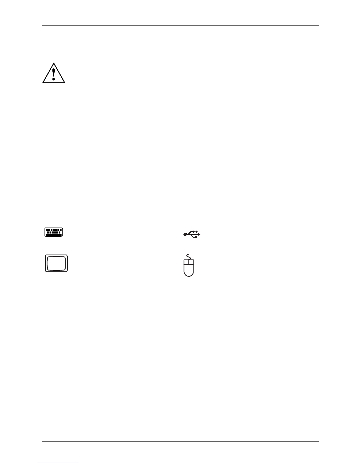
Connecting the monitor, mouse and keyboard
The ports for the monitor, mous
e, and keyboard are o n the front and rear of the device.
Keyboard port, purple
(optional)
USB port, black
(USB mouse, USB
keyboard)
Monitor port, blue
PS/2 mouse port,
green (optional)
PS/2 mouse port,
green
A26361-K1007-Z220-1-7619, edition 1 7
Page 16

Getting started
Connecting the monitor
► Follow the instructions contained in the monitor manual to prepare the monitor
for operation (e.g. connecting cables).
Monitor,
► C onnect the data cable of the monitor into the monitor port of your device.
The monitor power cable may only be connected to the device monitor socket if
the monitor current consumption is less than 1.5 A for 230 V or 3 A for 115 V.
The values for th e monitor current consumption can be found in the technical
data on the monitor or in the operating manual for the monitor.
1
2
► D epending on your device configuration level, plug the monitor power cable into
either the system unit (1) or a grounded mains ou tlet (2).
8 A26361-K1007-Z220-1-7619, edition 1
Page 17
Getting started
Connecting the mouse
Depending on the equipment level selected, your device will be supplied with
a USB mouse or a PS/2 mouse.
Mouse,Connecting,
Connecting a USB mouse
► Connect the USB mouse to one of the U SB ports on the device.
USBport,USBport
Connecting a PS/2 mouse
If you do not attach a mouse to the PS/2 mouse port, you can disable the mouse
controller in the BIOS Setup in order to free the IRQ12 for a different application.
► Connect the PS/2 mouse to the PS/2 mouse port of the device.
PS/2mouse,Connecting,PS/2mouse,
Connecting the keyboard
Depending on the equipment level selected, your device will be supplied with
a USB keyboard or a PS/2 keyboard.
Keyboard,Connecting,
Connecting a USB keyboard
Use the supplied keyboard cable only.
USBport,Connecting,
► Plug the rectangular connector of the keyb
oard cable into the rectangular socket
on the underside or on the rear of the keyboa
rd.
► Insert the flat rectangular USB plug of the keyboard cable into one of the device’s USB ports.
USBport
Connecting a PS/2 keyboard
Use the supplied keyboard cable only.
ConnectingaPS/2keyboardConnecting,
► Plug the rectangular connector of the keyboard cable into the rectangular socket
on the underside or on the rear of the keyboard.
► Plug the round plug of th e keyboard cable into
the keyboard port on the device.
Keyboard,
Connecting the device to the mains voltage
(device-dependent)
Device,Connecting,Device,
The device is adjusted to the mains voltage depending on the configuration level:
• Devices that only support 230 V cannot be adjusted to the mains voltage.
• On devices with a WAN component, the voltage supply is automatically
adjusted t o the mains v oltage.
• On devices with a voltage selector switch (sliding switch, plug-in element)
you will need to manually select the correct voltage rating.
A26361-K1007-Z220-1-7619, edition 1 9
Page 18
Getting started
100 V - 127 V
200 V - 240 V
115
230
1
a
a
100 V - 127 V
200 V - 240 V
230
115
2
230
115
1 = Sliding voltage switch
over switch
2 = Plug-in voltage switchover element
a = Notch for inserting the
screwdriver
The visible value must correspond to the local mains voltage:
• 115 = 100 V to 127 V
• 230 = 200 V to 240 V
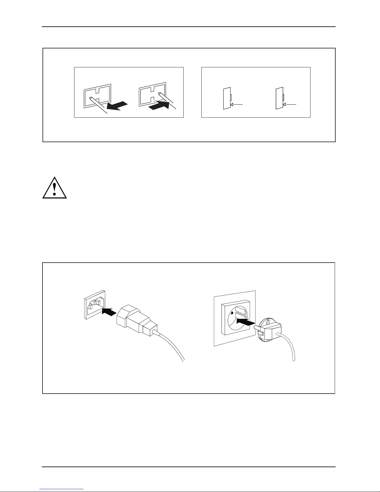
► C heck the voltage setting.
► If the incorrect mains voltage is selected, push the slide switch all the way into
the other available position (1) with a pointed object.
or
► In sert a screwdriver into the notch and prise out the plug-in element,
turn it and refit it the other way round (2).
2
1
► C onnect the po wer cable to the device (1).
► Plug the power plug into a grounded mains outlet (2).
10 A26361-K1007-Z220-1-7619, edition 1
Page 19

Getting started
Switchingonforthefirst time: installing the software
Installing,Software,Installing,
If the device is integrated into a netwo rk, the user and server details as well as the
network protocol are required during the software installation.
Contact your netwo rk administrator if you have any questions about these settings.
When you switch on the device for the first time, the supplied software is installed and configured.
Plan a reasonable amount of time for this, as this process must not be interrupted.
Once the installation ha s been started the device must not be switched
off, unless the installation has been completed.
During installation, the device may only be rebooted when you are requested to do so!
The installation will otherwise not be carried out correctly and the contents
of the hard disk must be completely restored.
You may need the licence number f
or Windows during the installation. The licence
number is located on a sticker o
n your device.
A26361-K1007-Z220-1-7619, edition 1 11
Page 20

Getting started
Switching on the monitor and device
DeviceMonitor
► Sw itch the monitor on (see the operating manual for the monitor).
► Sw itch the device on. To do this, follow the instructions below.
► Press the ON/OFF switch on the front of the device.
The power-on indicator lights green and the device is started.
12 A26361-K1007-Z220-1-7619, edition 1
Page 21

Getting started
Installing the software
► During installation, follow the on-screen instructions.
Software,Installing,
► Consult the operating system manual if there is anything unclear about the requested input data.
For further information about the system and its drive rs, utilities and updates please
refer to the "Drive rs & Utilities" DVD or visit our website at "
http://ts.fujitsu.com/support/".
Connecting extern al devices
Read the documentation on the external device be fore c onnecting it.
With the exception of USB devices, always remove all power plugs
before connecting external devices!
Do not connect or disconnect cables during a thunderstorm.
Always take hold of the actual plug. Never unplug a cable by pulling the cable itself.
Connect and disconnect the cables in the order described below.
Connecting the cables
► Turn off all power and equipment switches.
CordCable,
► Remove all power plugs from the gro unded mains outlets.
► Connect all the c ables to the device and the external devices. Please make sure that you
always observe the safety notes provided in "
Important notes", Page 3.
► Plug all data communication cables into the appropriate sockets.
► Plug all power cables into the grounded mains outlets.
USB devices are hot-pluggable. This means yo u can connect and disconnect
USB cables while your device is switched on.
Additional information can be found in "
Connecting external devices to the USB
ports", Page 15 and in the documen tation for the USB devices.
Disconnecting the cables
► Switch off all affected devices.
Cable,
► Remove all power plugs from the gro unded mains outlets.
► Unplug all data communication cab
les from the appropriate sockets.
► Disconnect all of the cab les from the device and from the external devices.
A26361-K1007-Z220-1-7619, edition 1 13
Page 22

Getting started
Ports on the device
InterfacesExternaldevices,D evice,
The ports are located on the front and back of th e device. The ports available on your
device depend on the configuration level you have selected. The standard ports are
marked with the symbols shown below (or similar). Detailed information on the location
of the ports is provided in the manual for the mainboard.
Serial interface,
turquoise
Serialinterface
Microphone port, pink
(optional)
Microphoneport
Monitor port, blue
Monitorport
Audio input (Line in),
light blue
AudioinputLinein
Headphones, orange
or light green (optional)
Headphones
Audio output (Line out),
light green
AudiooutputLineout
USB - U niversal Serial
Bus, black
UniversalSerialBus
LAN
LAN po rt
LANport
PS/2 mouse port,
green (optional)
MouseportPS/2mouseport
Keyboard port, purple
(optional)
Keyboardport
Some of the connected devices require special drivers (see the
documentation for the connected device).
14 A26361-K1007-Z220-1-7619, edition 1
Page 23

Getting started
Connecting external devices to the serial interface
SerialinterfaceSerialinterface,Externaldevices,Device s,
External devices can be connected to the serial interface (e.g. a printer or modem).
► Connect the data c able to the external device.
► Connect the data cable to the corresponding serial interface.
For an exact description of how to connect external devices to the corresponding
port, please see the external device documentation.
Port settings
Serialinterface,
You can change the port settings (e.g. address, interrupt) in the BIOS Setup.
Device drivers
Devicedrivers,
The devices connected to the serial interface require drivers. Your o perating system
already includes many drivers. If the required drive is missing, install it. The latest
drivers are usually available on the Internet or will be supplied on a data carrier.
Connecting external devices to the U
SB ports
USBdevices,USBport,Externaldevices,Devices,
You can connect a wide range of external devices to the USB ports (e.g.
printer, scanner, modem or keyboard).
USB devices are hot-pluggable. This means yo u can connect and disconnect
USB cables while your device is switched on.
Additional information can be found in the d ocumentation for the USB devices.
► Connect the data c able to the external device.
► Connect the data cable to one of the USB
ports on your device.
Device drivers
The external U S B devices you connect
to the USB ports usually require no
driver of their own, as the required s
oftware is already included in the operating
system. However, if the external USB
device requires its own software, please
install it from the data carrier pr
ovided with the USB device.
To ensure USB 2.0, the length of the
cable used between the front USB port of
your device and the external USB de
vice must not exceed 3 m.
A26361-K1007-Z220-1-7619, edition 1 15
Page 24

Operation
Operation
Switch the device on
► If necessary, switch the monitor on (see the operating manual for the monitor).
Device,Monitor,
► Sw itch on the device using the main
power switch located on the rear o f the device (if present).
► Press the ON/OFF switch on the front of the device.
The power-on indicator lights gr
een and the device is started.
Switching off the device
► Shu t down the operating system in a defined manner. In Windows: via the
Start menu and the Turn Off Computer function.
Device,Monitor,
► If the operating system does not au
tomatically switch the device into energy-saving
mode or switch it off, press the ON
/OFF switch.
If the device is in standby, it c onsumes a minimum of energy.
► Sw itch the device off at the main swi
tch (if present). The device no longer uses any power.
ThemainswitchandtheON/OFFswit
ch do not disconnect the device
from the mains voltage. To comple
tely disconnect the mains voltage,
remove the power plug from the p
ower socket.
► If necessary, switch the monitor off (see the operating manual for the monitor).
16 A26361-K1007-Z220-1-7619, edition 1
Page 25

Operation
Indicators on the device
Indicators,Device,
The indicators are on the front of the casing. Which indicators are available on your
device depends on the configuration level you have selected.
2
1
3
1 = Drive indicator, e.g. DVD
2 = Hard disk indicator
3 = Power-on indicator
3
1
2
4
1 = Drive indicator, e.g. DVD
2 = Floppy disk indicator
3 = Hard disk indicator
4 = Power-on indicator
A26361-K1007-Z220-1-7619, edition 1 17
Page 26

Operation
Hard disk indicator
The indicator lights up when the device’s hard disk is accessed.
Power indicator
PowerindicatorPoweri ndicator,Pow erindicator,Powerindicator,Powerindicator,
In energy-saving mode, the device must not be switched off with the main power switch
(if present) or disconnected from the mains, as this may result in data loss.
• The indicator is green: the device is on.
• Indicator lights up orange or flashes green (depending on the type of device): Device is in
power-saving mode. After being switched on with the On/Off switch, the device switches
on or returns to the state it was in before it went into power-saving mode.
• The indicator fails to light: the device is switched off (main switch on 0 or
disconnected from the power supply) or is ready for operation. If the device is
ready it can be switched on using the ON/OFF switch.
Floppy disk indicator (optional)
Floppydiskdrive,
The indicator lights up when the device’s floppy disk drive is accessed. You may
only remove the floppy disk when the indicator is not on.
Drive indicator, e.g. DVD
DVDindicatorDVDindicator,CD-ROMindicatorCD-ROMdrive,
The indicator lights up when the CD-ROM or DVD d rive is accessed. You may
only remove the DVD when the indicator is dark.
18 A26361-K1007-Z220-1-7619, edition 1
Page 27

Operation
Keyboard
KeyboardKeyboard,Keyboard,Keyboard,Keyboard,Keyboard,Alphanumerickey padCursorkeysKeys,FunctionkeysNumerickeypadNumerickey pad
1 2
345
1 = Function keys
2 = On/off switch (optional)
3 = Alphanumeric keypad
4=Cursorkeys
5 = Numeric keypad (calculator keypa
d)
The illustrated keyboard is an example and may differ from the model you use.
A26361-K1007-Z220-1-7619, edition 1 19
Page 28

Operation
Important keys and keyboard shortcuts
KeysKeyboardshortcuts
The description of the following keys and keyboard shortcuts applies to Microsoft
operating systems. Details of other keys and keyboard shortcuts can be found in
the documentation for the relevant application program.
ON/OFFswitchButton,
On/off switch (optional)
Depending on the setting in the BIOS Setup, the device can be
switched on or off with this switch. Some operating systems allow
you to configure additional functions of the ON/OFF switch in the
Control Panel.
With some keyboards the ON/OFF sw itch can o nly be used with an
ACPI (Advanced Configuration and Power Management Interface).
Otherwise the key is inoperative . The mainboard must support this
function.
Keys,Keys,Keys,
Enter key
confirms the highlighted selection. The Enter key is also referred to
as the "Return" key.
Start key
Keys,
calls up the Windows Start menu.
Keys,
Menu key
calls up the menu for the marked item (Windows).
Keys,Keys,
Shift key
enables upper-case letters and the upper key symbols to be displayed.
Keys,
Alt Gr key
produces a character shown on the bottom right of a key (e.g. the @
sign on the
Q
key).
Keys,
Num Lock key
By pressing the Num Lock key you sw itch between the upper- and
lower-case levels of the calculator keypad.
When the Num Lock indicator is lit the numeric keypad and arithmetic
keys are active.
When the Num Lock indicator is not lit the cursor control functions on
the Numeric keypad are active.
20 A26361-K1007-Z220-1-7619, edition 1
Page 29

Operation
Ctrl
Keys,Keys,Keys,Keys,
Ctrl key
performs a special operation when pre
ssed in conjunction with another
key. The
Ctrl
keyisalsoreferredtoas"Con
trol" or the "Control k ey".
AltCtrl
Del
SysRq
++
WarmrebootCtrl+Alt+DelKeys,keyboardshortcuts
Warm restart
restarts your device. Press simultaneously the ke ys
Ctrl,Alt
and
Del
.
Under some operating systems the Task Manager appea rs first. You
must then press all three keys again to reboot.
Settings in BIOS Setup
BIOSSetup,Systemsettings,BIOSSetup,BIOSSetup,BIOSSetupSetup,
In BIOS Setup, you can set the system functions and the hardware configuration of the device.
When the PC is delivered, the default entries are valid (see "BIOS Setup" manual or manual for
the mainboard). You can customise these settings to your requirements in the BI O S Setup.
Property and data protection
PropertyprotectionDataprotectionSecuritymeasures
Software functions and mechanical locking offer a broad range of functions for protecting your
device and your personal data from unauthorised access. You can also combine these fun ctions.
A26361-K1007-Z220-1-7619, edition 1 21
Page 30

Operation
Anti-theft protection and lead-sealing
Device,Device,C asing,Lead-sealingAnti-theftprotectionKensingtonLockChain
1
2
1 = Holes for padlock 2 = Device for "Kensington Loc
k"
Anti-theft protection
You can protect your devic
e from theft
• with the holes (1), a padlo
ck and a chain, which y ou have connected to a fixed object beforehand.
• with the Kensington Lock device (2) and a Kensington MicroSaver. Consult
the m anual for your Kensington Lock.
Lead-sealing
The casing can be sealed to prevent it being opened by unauthorised persons. To do this, feed
the sealing chain through the holes (1) and seal the chain with the lead seal.
22 A26361-K1007-Z220-1-7619, edition 1
Page 31

Operation
BIOS setu p security functions
Securityfunctions,BIOSSetup,
The Security menu in BIOS Setup offers you various options for protecting your
personal data against unauthorized access, e.g.:
• Preventing unauthorised access to BIOS Setup
• Preventing u nauthorised system access
• Preventing unauthorised access to the settings of boards with their own BIOS
• Preventing the system from booting from the diskette drive
• Issuing virus warnings
• Preventing the unauthorised writing of floppy disks
• Protecting BIOS from overwriting
• Protecting the device from being switched on by an external device
You can also combine these functions.
You wil l find a detailed description of the Security menus and how to assign passwords
in the manual for the mainboard or in the "BIOS Setup" manual.
Access authorisation via SmartCard
Securityfunctions,Accesspermission,SmartCard
In systems equipped with a SmartCard re
ader, access can be restricted to those
users who have a corresp onding SmartCa
rd.
A26361-K1007-Z220-1-7619, edition 1 23
Page 32

Operation
Access protection with SystemLock
Securityfunctions,Securityfunctions,
With SystemLock, you can protect your system from un authorised booting. A system can then only
be booted when the user inserts a valid SmartCard into the SmartCard reader and enters his/her
personal code number (PIN). To use SystemLock, you require the following components:
• External or internal SmartCard reader
• SystemLock installed (see "BIOS Setup" manual)
• SmartCard
SystemLock controls access to your device. W hen a SmartCard is initialised, permissions
are assigned for system access (system, setup, system+se tup, admin). You can con figure
several SmartCards for one system and initialise them with different permissions. In
addition, you can protect access to your hard disk
In this way users can be divided into user groups. Users of a user group
use SmartCards with the same permissions.
IfyoualsowanttouseothersecuritysoftwareinadditiontoSystemLock (e.g. SMARTY),
please read your security software d ocumentation beforehand.
SystemLock rig hts
You can initialise a SmartCard with one of the following r ights:
System The system starts f ol lowing e
ntry of the user PIN. You can change the user
PIN.
Setup
You can open and change the BIO
SSetupand change the user PIN.
System+Setup The system starts following entry of the user PIN. You can open and change
the B IO S Setup and change the user PIN.
Admin
The system starts f ollowing e
ntry of the user PIN. You can change the user
PIN and the administrator PIN
, unlock locked SmartCard s, open and change
the BIOS Setup and genera te ad
ditional SmartCards for this system.
For instructions on ho w to install and use SystemLock, and how to initialise
SmartCards, see the "BIOS Setup" manual.
Operating the SmartCard reader
► C onnect the external SmartCard reader to your system as described in
the instructions for the SmartCard reader.
SmartCardreader,
After the device is switched on, you will be prompted to insert your SmartCard.
24 A26361-K1007-Z220-1-7619, edition 1
Page 33

Troubleshooting and tips
Troubleshooting and tips
Refer to the safety notes in the "Safety" manual and in the "Getting started",
Page 6 chapter when connecting or disconnecting cables.
If a fault occurs, try to correct it as described in the following documentation:
• in this chapter
• in the documentation for the connecte d devices
• in the help systems of the software used
• in the documentation for your operating system
Help if problems occur
Should you ever have a problem with your computer that you cannot solve yourself, in many cases
you can solve it quickly using the SystemDiagnostics program pre-installed on your computer.
► To start the SystemDiagnostics programme, click on Startsymbol - P rogram -
Fujitsu Siemens Computers - SystemDiagnostics
or
► To s t a rt t h e SystemDiagnostics programme, click on Startsymbol - Program
- Fujitsu - SystemDiagnostics.
► If a problem is detected duri
ng the test run, the SystemDiagnostics program outputs
a code (e.g. DIFS code YXXX1
23456789123).
► Take a note of this DIFS code and the ID number of your device. The ID number can
be found on the type rating plate on the back of the casing.
► For further clarification of
the problem, contact the Help Desk for your country (see the
Help Desk list or visit th e In
ternet at "
http://ts.fujitsu.com/support"). For this, please have
ready the ID number & seria
l number of your system and the DIFS code.
A26361-K1007-Z220-1-7619, edition 1 25
Page 34

Troubleshooting and tips
Troubleshooting
Power indicator remains off after you have switched
on your device
Cause
Remedy
The mains voltage supply i s faulty. ► Ch eck whether the power cable is properly
plugged into the device and a grounded
mains outlet.
► Switch the device on.
Internal power supply overlo
aded.
► Pull the power plug of the device out of the
mains outlet.
► Wait a moment.
► Plug the power plug into a properly grounded
mains outlet again.
► Switch the device on.
The device cannot be switched off with the ON/OFF switch.
Cause
Remedy
The device has not been switc
hed on with the
ON/OFF switch.
► Pre ss the ON/OFF switch again.
System crash ► Pre ss the ON/OFF switch for at least
4 seconds, until the device switches off.
The operating system is not shut-down properly
in the process. Error messages are therefore
possible the next time the system is booted.
Monitor remains blank
Cause
Remedy
Monitor is switched off. ► Switch your monitor on.
Power saving has been activated (screen is
blank)
► Pre ss any key on the keyboard.
or
► De activ a te the scr een sa
ver. If
necessary, enter the a
ppropriate
password.
Brightness control is
set to dark
► Adjust the brightness
control. For detailed
information, please r
efer to the operating
manual supplied with y
our monitor.
26 A26361-K1007-Z220-1-7619, edition 1
Page 35

Troubleshooting and tips
Cause
Remedy
Power cable not connected
► Sw itch off the monitor and the dev
ice.
► C heck that the monitor power cable is
properly connected to the monitor and to
a grounded mains outlet or to the monitor
socket of the device.
► C heck that the device power cable
is
properly plugged into the devi
ce and a
grounded mains outlet.
► Sw itch on the monitor and the device.
Monitor cable not connected
► Sw itch off the monitor and the device.
► C heck that the m onitor cable is properly
connected to the device and monitor.
► Sw itch on the monitor and the device.
Wrong monitor has been set under
Windows 2000
► R estart the device.
► When the message Windows is starting up
appears, press function key
F8
.
The Windows 2000 Advanced Options menu
appears.
► Select Safe Mode or Safe Mode with Network.
► Go to Star t – Settings – Control Panel – Display
– Settings to enter the correct values for
the connected monitor as described in the
operating manual of the monitor.
Wrong monitor has been set under Window XP ► R estart the device.
► Press
F8
while the system is booting.
Either the Windows Advanced Start Options menu
or the menu for selecting the operating system
appears.
► If the menu for selecting the operating
system appears, press
F8
.
► Select Safe Mode or Safe Mode with Network.
► Go to Star t – Settings – Control Panel – Display
and the tabs Appearance, Themes, Settings
to set the correct values for the c onnected
monitor as described in the operating
manual o f the monitor.
A26361-K1007-Z220-1-7619, edition 1 27
Page 36

Troubleshooting and tips
Cause
Remedy
Wrong monitor has been set under Windows
Vista
► Re start the device.
► Press
F8
while the system i s booting.
Either the Windows Advanced Start Options menu
or the menu for s electing the operating system
appears.
► If the menu for selecting the operating
system appears, press
F8
.
► Select Safe Mode or Safe Mode with Network .
► Go to Start symbol – (Settings) – Control
Panel – Appearance and Personalization –
Personalization and enter the correct values
for the connected monitor as described in
the operating m anual of the monitor.
The wrong RAM modules have been inserted
► See the technical manual for t
he mainboard
for information on which memo
ry modules
canbeused.
No mouse pointer displayed
on the screen
Cause
Remedy
The mouse is not correctly connected.
► Shut down the operating system properly.
► Switch the device off.
► Ch eck that the mouse cable is properly
connected to the system unit. If you use an
adapter or extension lead with the mouse
cable, check the connections.
► Make sure that only one mous
eis
connected.
► Switch the device on.
The floppy disk cannot be read or written
Cause
Remedy
The write pro tection of t
he floppy disk or the
floppy disk drive is activ
ated.
► Ch eck whether the w rite p
rotection of
the floppy disk or the flopp
ydiskdriveis
activated (refer to th
e "BIOS Setup" manual
and if necessary to the
manual for the
mainboard).
The floppy disk drive controller is not ena bled. ► Check the relevant entries for floppy disk
driveintheMain menu of th e BIOS Setup.
► Ch eck that the floppy disk drive controller
is enabled (refer also to the manual for the
mainboard or in the "BIOS Setup" manual).
The floppy disk drive is not connected. ► Ch eck that the cables of the floppy disk
drive are properly connected.
28 A26361-K1007-Z220-1-7619, edition 1
Page 37

Troubleshooting and tips
Time and/or date is not correct
Cause
Remedy
Time and date are incorrect.
► Se t the correct time and date within the
operating system you are using.
or
► Se t the correct time and/or date in th e
BIOS Setup.
The on-board backup battery in the d evice is flat. ► If the time and date are repeatedly wrong
when you switch on your device, replace the
lithium battery (see "
Replacing the lithium
battery", Page 49).
Error messa ges on the screen
Error messages and their explanations are provided:
• in the technical manual for the mainboard
• in the documentation for the program s used
Installing new software
When installing programs or drivers, important files may be overwritten and modified. To
be able to access the original data in the event of any problems following installation,
you should backup your hard disk prior to installation.
Restoring hard disk contents
Should you need to restore your hard disk, the instructions a re provided on the case
of the "Recovery DVD" (delivered with your system).
Tips
Topic Ti p
Outofsystemresources ► C lose unnecessary applications.
or
► R un the applications in
a different order.
Other manuals Further manuals are provided as PDF files on
the "Drivers & Utilities" DVD.
A26361-K1007-Z220-1-7619, edition 1 29
Page 38

System exp ansio ns
System expansions
Upgrades,Device,Systemexpansion
As the device has to be shut down in order to install/uninstall system hardware
components, it is a good idea to print out the r elevan t sections of this chapter.
It may be necessary to update the BIOS when carrying out a system expansion
or hardware upgrade. Additional information is contained in the "BIOS Setup"
manual or possibly in the technical manual for the mainboard.
When installing components that become very hot, m ake s ure that the
maximum permissible temperature is not exceeded.
The device must be switched off when installing/removing the system
expansions and may not be in energy-saving mode.
Remove the power plug before opening the device.
This chapter describes all the activities required to modify your device hardware
(e.g. installing boards or drives).
Read the supplied documentation before installing new drives and/or boards.
Refer to the manual for the mainboard before making any extensions to the mainboard .
Information about boards
Take care w ith the locking mechanisms ( ca tches and centring pins) when you
are replacing boards or co m ponents on boards
To preven t damage to the board or the c omponents and conductors on it, please take care when
you insert or remove boards. Make sure expansion boards are inserted straightly.
Never use sharp objects (screwdrivers) for leverage.
Boards with electrostatic se
nsitive devices (ESD) are identifiable by the label
shown.
When handling boards fitted w
ith ESDs, you must always observe the
following points:
• You must always discharge st
atic build up (e.g. by touching a grounded
object) before working.
• The equipment and tools you use must be free of static charges.
• Only touch or hold the boards
by the edge or at the areas marked green
(Touch Points).
• Never touch pins or conductors on boards fitted with ESDs.
30 A26361-K1007-Z220-1-7619, edition 1
Page 39

System expansions
Opening the casing
Casing,Device,
Note that some components on the mainboard may be very hot if the device was in
use shortly before the casing was removed.
These components can be marked with the following symbol.
► Switch the device off. The device must not be in power-saving mode.
Please observe the safety information in "Important notes", Page 3.
Disconnect the mains plug from the mains outlet.
Only insert the power plug after you have c losed the casing.
► Remove any connected wires which are in the way.
► Lay the device on its side in the ma
nner shown below.
1
1
3
2
► For devices with screwed on side part: Remove t he casing screws (1).
► Pull the locking device (2) and swivel the side part in the direction of the arrow (3).
A26361-K1007-Z220-1-7619, edition 1 31
Page 40

System exp ansio ns
Closing the casing
► In sert the side part in the guide rail on the lower part of the casing.
Casing,Device,
► In sert the side part in the guide rail on the lower part of the casing.
2
2
1
► Sw ivel the side part in the direction of the arrow (1) until it engages.
► For devices with screwed on side part: Tighten the casing screws (2).
► R eco nnect the cables that you disconnected previously.
32 A26361-K1007-Z220-1-7619, edition 1
Page 41

System expansions
Removing and installing the ven
tilation duct.
Removing the ventilation duct
Ventilationduct,
When removing the ventilation duct, be careful not to damage the
processor cooler(s) on the mainboard.
2
1
► Open the c asing (s ee "Opening the casing", Page 31).
► Unhook the cables
from the holder on the ventilation duct.
► Remove any plugged-in cables that are in the way.
► Unlock the ventila
tion duct by pressing the locking hooks in the direction of the arrow (1).
► Keep pressing the locking hook and pull the ventilation duct out of the
casing in the direction of th e arrow (2).
A26361-K1007-Z220-1-7619, edition 1 33
Page 42

System exp ansio ns
Installing the ventilation duct
Ventilationduct,
When fitting the v entilation duct, be careful not to damage the
processor cooler(s) on the m ainb oard.
1
► In sert the latch
es on t he underside of the ventilation duct into the corresponding slots in the casing.
► Press the ventilation duct into the casing in the direction of the arrow (1)
until you feel the locking hook engage.
► R eco nnect the cab
les that you disconnected previously.
► H ook the cables into the holder on the ventilation duct.
► C lose the casing (s
ee "
Closing the casing", Page 32).
34 A26361-K1007-Z220-1-7619, edition 1
Page 43

System expansions
Installing and removing a board
The number, position and arrangement of the board slots on the mainboard can be fou nd in
the manual for the mainboard. Boards may already be installed on shipment.
Board,Board,
Installing a board
► Open the c asing (s ee "Opening the casing", Page 31).
Board,
1
2
► Remove the screw on the slot c over (1).
► Pull the slot cover out of the slot in the direction of the arrow (2).
A26361-K1007-Z220-1-7619, edition 1 35
Page 44

System exp ansio ns
Do not throw a way the slot cover. For cooling, protection against fire and in order to
comply with EMC regulations, you must refit the slot cover if you remove the board.
2
1
► Push the board into the slot (1).
► Screw the screw back onto the slot cover (2).
► If necessary, connect the cables to the board.
► C lose the casing (see "
Closing the casing", Page 32).
If you have installed or removed a board, please check the releva nt PCI
slot settings in the BI OS Setup. If necessary, change the settings. Further
information is provided in the PCI board documentation.
Information about the installation of low profile boards can be found in
the "
Low-profile boards", Page 38 chapter.
Removing boards
► Open the casing ( see
"
Opening the casi ng", Page 31).
Board,
► D isconnect the cables connected to the board.
36 A26361-K1007-Z220-1-7619, edition 1
Page 45

System expansions
1
2
► Remove the screw on the board (1).
► Pull the board out of the slot in the direction of the arrow (2).
► Place the board into appropriate packaging.
For cooling, prot ection against fire, and in order to comply with EMC ( electromagne tic
compatibility) regula tions, you must refit the slot cover.
2
1
► Push the slot cover into the slot (1).
A26361-K1007-Z220-1-7619, edition 1 37
Page 46

System exp ansio ns
► F asten the slot cover into place with the screw (2).
► C lose the casing (see "
Closing the casing", Page 32).
If you have installed or removed a PCI board, please check the relevant PCI
slot settings in the BI OS Setup. If necessary, change the settings. Further
information is provided in the PCI board documentation.
Low-profile boards
Low-profileboard
You will need to fit a corresponding slot adapter first before you can install a
low-profile board in a normal board slot.
Two-piece slot covers are fitted to the slots intended f or low-pro file boards. The
two pieces are joined together by a screw.
Do not throw a way the slot cover. For cooling, protection against fire and in order to
comply with EMC regulations, you must refit the slot cover if you remove the board.
EMC,electromagne
ticcompatibility
► R emove the required slot cover (see "Installing and removing a board", P age 35).
Fitting a slot adap ter
2
1
► F it the slot adapter to the s lot cover of the low-profile board (1) and screw tight (2).
Low-profileboards,
Now you can install the low-profile board in a suitable slot like a normal board
(see "
Installing and removing a board", Page 35).
38 A26361-K1007-Z220-1-7619, edition 1
Page 47

System expansions
Removing a slot adapter
2
1
► Unscrew the screw (
1) and remove the slot adapter (2).
Low-profileboards,
Installing and removing drives
DriveDrive,Drive,Drive,31/2-inchdrive51/4-inchdriveDrive,
The PC casing can accommodate a total of four drives:
• three accessible drives (two 5¼-inch drives and one 3½-inch drive)
• two non-accessible hard dis
k drives(tw o 3½-inch drives with half installation height)
"Accessible drives" are e.g. DVD or CD ROM drives, into which a data
carrier can be inserted from outside.
Removing and installing accessible drives
The number of screws used to attach the drives varies according to the type of
drive fitted and may not necessarily match the depiction below.
A26361-K1007-Z220-1-7619, edition 1 39
Page 48

System exp ansio ns
Removing an accessible 51/4inch drive (e.g. DVD drive)
► Open the casing ( see " Opening the casin g", Page 31).
Accessible drive,Drive,
► D isconnect all cables connected to the drive (data ca ble, power supply cable).
1
2
► Lo osen the screws (1).
► Working from behind, slide the drive a short distance out of the bay in the direction of the arrow (2).
The drive now protrudes slightly out of the casing.
► Pull the drive out of the casing (2).
► If necessary, make the required settings on the remaining hard disk drive.
40 A26361-K1007-Z220-1-7619, edition 1
Page 49

System expansions
2
1
► If you are not installing a new drive, slide the empty slide-in module as
far as it will go into the casing (1).
► Secure the empty sli
de-in module with the screws (2).
► Close the casing (see "
Closing the casing", Page 32).
It may be necessary to modify the entry for the remaining drives in the BIOS Setup.
A26361-K1007-Z220-1-7619, edition 1 41
Page 50

System exp ansio ns
Installing an accessible 51/4inch d r ive (e.g. DVD drive)
► Open the casing ( see " Opening the casin g", Page 31).
Accessible drive,Drive,
► If a slide-in module is fitted, remove this first. To do this, proceed in the same way as when
removing a drive (see "
Removing an accessible 51/4inch drive (e.g. DVD drive)", Page 40).
Do not dispose of the empty slide-in module. For cooling, protection against
fire, and in ord er to comply with EMC regulations, you must refit the empty
slide-in module if you remove the drive again later.
► Take the new drive out of its packaging.
► Ma ke the desired settings on the new drive (if necessary, to the setting s of
drives already installed as well (Ma ster/Slave)).
2
1
► Slide the drive into the casing as far as it will go (1).
► Fasten the drive in place with the screws (2).
► Plug the data and the power supply connectors into the drive. Make sure the polarity is correct.
► C lose the casing (see "
Closing the casing", Page 32).
It may be necessary to modify the entry for the drive in the BIOS Setup.
42 A26361-K1007-Z220-1-7619, edition 1
Page 51

System expansions
Installing and removing an accessible 31/2inch drive (e.g. diskette drive)
► Open the c asing (s ee "Opening the casing", Page 31).
Floppydiskdrive,Floppydisk drive,
► Disconnect all cables connected to the drive (data cable, power supply cable).
2
1
► Remove the screws (1).
► Working from behind, slide the floppy disk drive out of the bay in the direction of the arrow (2).
► Slide the new floppy disk drive into the case in the opposite direction to the arrow (2).
► Fasten the floppy disk drive into place with the screw (1).
► Fit the data and power supply connectors to the floppy disk drive. Make sure the polarity is correct.
► Close the casing (see "
Closing the casing", Page 32).
It may be necessary to modify the entry for the drive in the BIOS Setup.
A26361-K1007-Z220-1-7619, edition 1 43
Page 52

System exp ansio ns
Installing and removing the hard disk drive
Harddiskdrive,Harddiskdrive,Harddiskdrive,
Removing a hard disk drive
► Open the casing ( see " Opening the casin g", Page 31).
Harddiskdrive,
► D isconnect all cables connected to the drive and fan (data c able, power supply cable).
1
2
1
► Lo osen the screws (1).
► Pull the drive backwards a short way out of the bay in the direction of the arrow (2).
The drive now protrudes slightly out of the bay.
► Pull the drive completely out of its bay. Make sure that you are not touching other components.
► If necessary, make the required settings on the remaining hard disk drive.
► C lose the casing (see "
Closing the casing", Page 32).
It may be necessary to modify the entry for the remaining drives in the BIOS Setup.
44 A26361-K1007-Z220-1-7619, edition 1
Page 53

System expansions
Installing a hard disk drive
► Open the c asing (s ee "Opening the casing", Page 31).
Harddiskdrive,
► Take the new hard disk drive out of its packaging.
1
1
2
► Slide the hard disk drive into the casing as far as it will go (1).
► Fasten the drive in place with the screws (2).
► Connect the cables (data cable, power supply) to the drive and to the fan.
► Close the casing (see "
Closing the casing", Page 32).
A26361-K1007-Z220-1-7619, edition 1 45
Page 54

System exp ansio ns
Installing an additional hard disk drive
You can install an additional hard disk drive in place of the accessible CD/DVD drive.
► Remove the accessible CD/DVD drive (see "
Removing an acce ssible 51/
4
inch drive (e.g. DVD drive)", Page 40).
Secondharddisk,
2
1
► Slide the additional hard disk drive into the drive carrier (1).
► C onnect th e cables to
the additional hard disk drive.
► Fasten the additional hard disk drive with the screws (2).
► C onnect the cables (da
ta ca ble, power supply) to the drive.
► C lose the casing (see "
Closing the casing", Page 32).
46 A26361-K1007-Z220-1-7619, edition 1
Page 55

System expansions
Installing USB ports on the rear panel
Depending on your ESPRIMO model, an insta llation slot for USB interfaces is provided
on the back of the casing. A s a result, no board slot is occupied.
1
► Insert a screwdriver into the opening and break ou t the pre-stamped installation
opening by moving it backwards and forwards.
USBports,USB ports,
► Slide the USB ports into the slot and secure them with the screw (1).
► Connect the USB cable to the mainboard – refer to the mainboard manual for details.
Mainboard expansi
ons
Details on how to upgrade the main memory or the processor of your device
can be found in the manual for the mainboard.
UpgradesLithium batteryProcessorMainmemoryMainboard
Upgrading main memory
► Open the c asing (s ee "Opening the casing", Page 31).
Mainme
mory,
► Upgrade the memory according to the description in the manual for the mainboard.
► Close the casing (see "
Closing the casing", Page 32).
A26361-K1007-Z220-1-7619, edition 1 47
Page 56

System exp ansio ns
Processor, replacing
► Open the casing ( see " Opening the casin g", Page 31).
Processor,rep lacing
► R emove the ventilation duct (see "Removing the venti lation duct", Page 33).
► U pgrad e the processor according to the description in the manual for the main board.
► In stall the ventilation duct (see "
Installing the ventilation d uct", Page 34).
► C lose the casing (see "
Closing the casing", Page 32).
48 A26361-K1007-Z220-1-7619, edition 1
Page 57

System expansions
Replacing the lithium battery
Incorrect replacem ent of the lithium battery may lead to a risk of explosion!
The lithium battery may be replaced only with an identical battery or with
a type recommended by the manufacturer.
Do not dispose of lithium batteries with household waste. They must be disposed
of in accordance with local regulations concerning special waste.
Make sure that you observe the correct polarity when replacing the lithium
battery. The plus pole must be face up!
Lithiumbattery,Replacing,Replacing,Replacing,lithiumbatteryBattery
The lithium b attery holder exists in different designs that function in the same way.
1
2
3
1
2
3
► Press the catch in the direction of the arrow (1).
The battery jumps out of the holder slightly.
► Remove the battery (2).
► Push the new lithium batte ry of the identical type into the holder (3) and
press it down until it engages.
A26361-K1007-Z220-1-7619, edition 1 49
Page 58

Technical data
Technical data
Electrical data
Regulations complied with:
IEC 60950-1, EN 60950-1, UL 60950CSA 22.2
No.60950-1
Protection class: I
Rated voltage range (selectable / non-selectable depending on the device type)
Rated voltage range (optionally selectable) 100 V – 127 V / 200 V – 240 V
Rated voltage range (non-selectable)
200 V - 240 V
Rated frequency
Rated frequency (selectable)
50Hz–60Hz
Rated frequency (non-selectable)
50 Hz
Rated current
Maximum rated current (optionally selectable) 100 V – 127 V / 6.0 A
200 V – 240 V / 3.0 A
Maximum rated curre nt (non-selectable) 200 V – 240 V / 3.0 A
Dimensions
Width/depth/height: 203 mm/387 mm/390 mm
Weight
in basic configuration:
approx. 11 kg
Environmental conditions
Environment class (3K2)
Environment class (2K2)
DIN IEC 721 part 3-3
DIN IEC 721 part 3-2
Temperature
Operating (3K2) 15 °C .... 35 °C
Transportation (2K2) –25 °C .... 60 °C
Condensation during operation is not p ermitted
The data sheets of these devices contains further technical data. You will find
the data sheets on the internet at "
http://ts.fujitsu.com/support/".
50 A26361-K1007-Z220-1-7619, edition 1
Page 59

Index
Index
3 1/2-inch drive 39
5 1/4-inch drive 39
A
Access permission, SmartCard 23
Accessible drive,
installing 42
removing 40
Alphanumeric keypad 19
Anti-theft protection 22
Audio input 14
Audio output 14
B
Battery 49
BIOS Setup 21
BIOS Setup,
configuration 21
security func tions 23
settings 21
system settings 21
Board,
installing 35
removing 35–36
Button,
ON/OFF switch 20
C
Cable,
connecting 13
disconnecting 13
Casing,
closing 32
lead-sealing 22
opening 31
CD-ROM drive,
indicator 18
CD-ROM indicator 18
CE marking 4
Chain 22
Connecting a PS/2 keyboard 9
Connecting,
device 9
keyboard 9
mouse 9
PS/2 keyboard 9
PS/2 mouse 9
USB keyboard 9
Contents of delivery 6
Cord
see Cable 13
Ctrl+Alt+Del 21
Cursor keys 19
D
Data protection 21
Device
Switching on 12
Device drivers,
serial interface 15
Device,
anti-theft protection 22
checking rated voltage 9
closing 32
connecting 9
indicators 17
lead-sealing 22
opening 31
ports 14
setting up 7
switching off 16
switching on 16
transporting 3
upgrades 30
Devices,
connecting 15
Disposal 3
Drive 39
Drive,
accessible 39
installing 39, 42
non-accessible drive 39
removing 39–40
Drivers & Utilities DVD 3
DVD indicator 18
DVD indicator,
indicator 18
E
Electromagnetic compatibility 4
EMC, electromagnetic compatibility 38
Energy saving 3
Ergonomic
video workstation 7
External devices,
connecting 15
ports 14
A26361-K1007-Z220-1-7619, edition 1 51
Page 60

Index
F
Floppydiskdrive,
indicator 18
removing 43
replacing 43
Function keys 19
G
Getting started 6
H
Hard disk drive,
installing 44–45
removing 44
replacing 44
Headphones 14
I
Important notes 3
Indicators,
device 17
Installing,
software 11, 13
switchingonforthefirst time 11
Interfaces 14
K
Kensington Lock 22
Keyboard 19
Keyboard port 14
keyboard shortcuts 21
Keyboard shortcuts 20
Keyboard,
alphanumeric keypad 19
connecting 9
cursor keys 19
function keys 19
numeric ke ypad 19
port 9
Keys 20
Keys,
Alt Gr 20
Control 21
Ctrl 21
Ctrl key 21
Ctrl+Alt+Del 21
cursor keys 19
Enter 20
Enter key 20
menu key 20
Num Lock 20
Return 20
shift 2 0
shift key 20
Start key 20
L
LAN port 14
Lead-sealing 22
Line in 14
Line out 14
Lithium battery 47
Lithium battery,
replacing 49
Low voltage directive 4
Low-profile bo ard 38
Low-profile boards,
fitting a slot adapter 38
removing a slot adapter 39
M
Main memory 47
Main memory,
upgrading 47
Mainboard
Upgrades 47
Microphone port 14
Monitor
Switching on 12
Monitor port 14
Monitor,
connecting 8
switching off 16
switching on 16
Mouse port 14
Mouse,
connecting 9
N
Note
safety 3
Notes
CE marking 4
important 3
Numeric keypad 19
O
ON/OFF switch 20
Overview
device 1
52 A26361-K1007-Z220-1-7619, edition 1
Page 61

Index
P
Packaging 6
Packaging,
unpacking 6
Power indicator 18
Power indicator,
flashes 18
green 18
off 18
orange 18
Preparing for first use, overview 6
Preparing for use,
overview 6
Processor 47
Processor, replacing 48
Property protection 21
PS/2 mouse port 14
PS/2 mouse,
connecting 9
port 9
R
Recycling 3
Replacing,
lithium battery 49
Replacing, lithium battery 49
Retransportation 3
S
Safety information 3
Second hard disk,
installing 46
Security functions,
BIOS Setup 23
SmartCard 23–24
SystemLock 24
Security measures 21
Serial interface 14–15
Serial interface,
connecting devices 15
settings 15
Setup,
see BIOS Setup 21
SmartCard r eader,
operating 24
Software,
installing 11, 13
System expansion 30
System settings,
BIOS Setup 21
System unit, see Device 3
T
Transportation 3
U
Universal Serial Bus 14
Upgrades
Mainboard 47
Upgrades,
device 30
USB devices,
connecting 15
USB port 9
USB port,
connecting devices 15
connecting keyboard 9
connecting the mouse 9
USB ports,
installing 47
rear panel of casing 47
User Documentation DVD 3
V
Ventilation duct,
installing 34
removing 33
Video workstation 7
W
Warm reboot 21
A26361-K1007-Z220-1-7619, edition 1 53
 Loading...