

Page 1

ESPRIMO Mobile V6515/V6555
EasyGuide
Page 2

Are there ...
... any technical problems or other questions that you would like help with?
Please contact:
• our Hotline/Help Desk (refer to the enclosed Help Desk List or go to:
"
http://ts.fujitsu.com/helpdesk")
• your sales partner
• your sales office
Additional information is contained in the Help Desk list and the "Warranty" manual. The
"Warranty" manual can be found on the supplied "Drivers & Utilities" CD/DVD.
The latest information about our products, useful tips, updates etc. is available
from our website: "
http://ts.fujitsu.com"
Page 3

Page 4

Published by
Fujitsu Technology Solutions GmbH
A26391-K245-Z220-1-7619, Edition 1
2009/04
Produced by
XEROX Global Services
Page 5

ESPRIMO Mobile V6515/V6555
Innovative technology... 1
Important notes
3
Ports and Operati
ng Elements
4
Removing and installing components
during servicing
16
Technical spe
cification
23
Index
25
EasyGuide
Page 6

Adobe and Acrobat are trademarks of Adobe Systems Incorporated and may
be protected in certain countries.
The Bluetooth trademarks are the property of Bluetooth SIG, Inc., U.S.A. licensed
for Fujitsu Technology Solutio ns GmbH.
Intel is a registered trademark, Core is a trademark of Intel Corporation, USA.
Kensington and MicroSaver are registered trademarks of ACCO World Corporation.
Microsoft, MS Windows and Windows Vista are registered trademarks of the Microsoft Corporation.
All other trademarks referenced are trademarks or registered trademarks of their
respective owners, whose protected rights are acknowledged.
Copyright © Fujitsu Technology Solutions G mbH 2009
All rights reserved, including rights of translation, reproduction by printing, copying
or similar methods, in part or in whole.
In the event of violations, perpetrators will be liable to prosecution for damages.
All rights reserved, including rights created by patent grant or registration of a utility model or design.
Subject to availability and technical m odifications.
Page 7

Contents
Contents
Innovativetechnology... ................................................................ 1
Notational conventions .................................................................. 2
Importantnotes ........................................................................ 3
Help ifproblemsoccur ................................................................... 3
Ports andOperatingElements ......................................................... 4
Switching on the notebook . . . . ........................................................... 5
Switching off the Notebook . . . ........................................................... 6
Status indicators ........................................................................ 7
Keycombinations ....................................................................... 9
Camera (depending on noteb ook model) . . . . . . ............................................ 11
Removing andinstalling thebattery ....................................................... 12
Removing the battery ................................................................ 12
Installingthe battery ................................................................. 12
SIM card (depending on your comp uter) . . . . . . ............................................ 13
Inserting the SIMcard ............................................................... 13
Removing aSIM card ............................................................... 14
Radio components: Wireless LAN/ Bluetooth/UMTS . . . .................................... 15
Switching the radio components on a nd off ............................................ 15
Removing and ins
talling components during servicing .. . . .............................
16
Notes on instal
ling andremovingboardsand components ..................................
16
Hard disk ............................................................................... 17
Removing the h
ard disk ..............................................................
17
Installing th
ehard disk ...............................................................
18
Removing and
installingmemory modules ................................................
19
Removing the
cover .................................................................
20
Removing mem
ory modules ..........................................................
20
Installing
amemorymodule ..........................................................
20
Attaching t
hecover ..................................................................
21
Removing a
ndinstalling theopticaldrive ..................................................
21
Removing t
heopticaldrive ...........................................................
21
Installi
ngtheopticaldrive ............................................................
22
Technical specification ................................................................. 23
Notebook . . ............................................................................. 23
Battery ................................................................................. 23
Mains adapter .......................................................................... 24
Mains adapter (65W) ................................................................ 24
Mains adapter (90W) ................................................................ 24
Index
..................................................................................
25
A26391-K245-Z220-1-7619, edition 1
Page 8

Contents
A26391-K245-Z220-1-7619, edition 1
Page 9

Innovative tech nology...
Innovative technology...
... and an ergonomic design make your notebook a reliable, convenient mobile PC.
Your notebook is available in several different versions. Most of the sections in this manual
apply to all models ‑ any differences are pointed out separately. Some of the illustrations and
features in this manual may differ from your model and are for guidance only.
Your Windows operating system is already pre-installed and optimally configured. That means
you’re ready to start when you switch on your notebook for the first time.
Your notebook features the very latest technology so that you get the best performance from
your computing experience. Depending on which model you own, you have access to:
• upto4GBofmainmemory(RAM)
• a CD/DVD burner-DVD for watching D VD movies and writing your own CDs and DVDs
• an integral camera for snapshots and video chat (depending on model)
• several USB ports which provide easy expansion with webcams, game pads, printers and more
• an internal modem for connecting to the Internet (optional)
• an ExpressCard slot for operating an ExpressCard/34 or ExpressCard/54
• a SIM card slot that can be used to operate a SIM card (depending on model)
• an integrated audio controller and two stereo speakers. You can even c onnect a
microphone and external speakers for even better sound performance.
With the user-friendly BIOS-Setup you can control the hardware of your notebook and protect your
system better against unauthorised access by using the powerful password features.
This operating manual describes how to get your notebook up and running and how to use it.
Further information on this notebook is provided:
• In the "Professional Notebook" Operating Manual
• In the "Safety" and "Warranty" manuals
• in the documentation of the operating system
• in the information files (e.g. *.TXT, *.DOC, *.WRI, *.HLP, *.PDF)
You c an find information on accessories for your Notebook at
"
http://ts.fujitsu.com/accessories".
A26391-K245-Z220-1-7619, edition 1 1
Page 10
Innovative t echnology...
Notational conventions
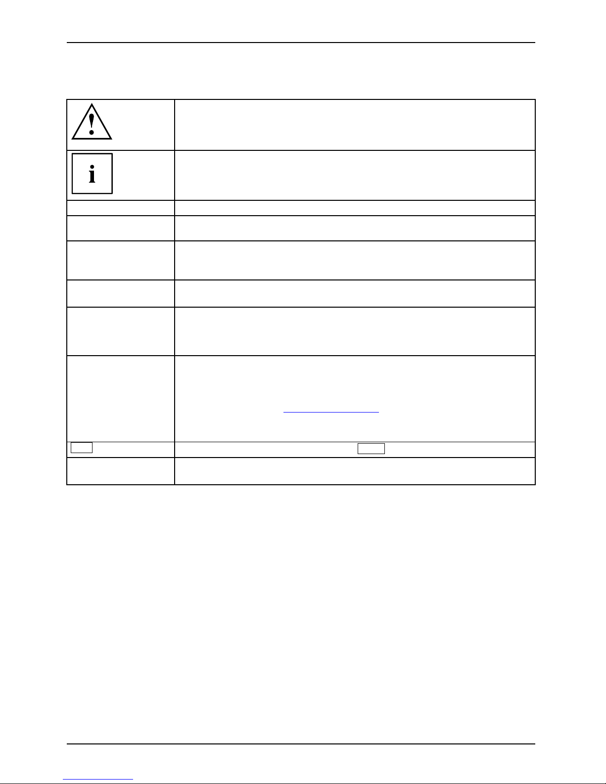
Pay particular attention to text marked with this symbol. Failure to observe
these warnings could pose a risk to health, damage the device or lead
to loss of data. The w arra nty will be invalidated if the device becomes
defective through failure to observe these warnings.
Indicates important informat
ion for the proper use of the device.
►
Indicates an activity that must be performed
Indicates a result
This font
indicates data entered usin
g the keyboard in a program dialogue or
command line, e.g. your pass
word ((Name123) or a command used to
start a program (start.ex
e)
This font
indicates information that is displayed on the screen by a program, e.g.:
Installation is complete.
This font
indicates
• terms and texts used in a software interface, e.g.: Click on Save
• names of programs or files, e.g. Windows or setup.exe.
"This f ont"
indicates
• cross-references to another section, e.g. "Safety information"
• cross-references to an external source, e.g . a web address: For more
information, go to "http://ts.fujitsu.com"
• Names of CDs, DVDs and titles or designations of other materials, e.g.:
"CD/DVD Drivers & Utilities" or "Safety" Manual
Abc
indicates a key on the keyboard, e.g:
F10
This font
indicates terms and texts that are emphasised or highlighted, e.g.: Do
not switch off the d evice
2 A26391-K245-Z220-1-7619, edition 1
Page 11

Important notes
Important notes
Take note of the safety hints provided in the "Safety" m anual, in the "Professional
Notebook" operating manual and in this manual.
Help if problems occur
Should you ever have a problem with your computer that you cannot solve yourself, in many cases
you can solve it quickly using the SystemDiagnostics prog ram pre-installed on your comput er.
► To start the SystemDiagnostics programme, click on Startsymbol - Program -
Fujitsu Siemens Computers - SystemDiagnostics
or
► To s t a r t t h e SystemDiagnostics programme, click on Startsymbol - Program
- Fujitsu - SystemDiagnostics.
► If a problem is detected du
ring the test run, the System Diagnostics program outputs
a code (e.g. DIFS c ode YXXX
123456789123).
► Take a note of this DIFS code and the ID numb er of your device. The ID number can
be found on the type rating plate on the back of the casing.
► For further clarification o
f the problem, contact the Help Desk for your country (see the
Help Desk list or visit the
Internet at "
http://ts.fujitsu.com/support"). For this, please have
ready the ID number & seri
al number of your system and the DIFS code.
A26391-K245-Z220-1-7619, edition 1 3
Page 12

Ports and Operating Elements
Ports and Operating Elements
This chapter presents the individual hardware components. This will pro vide you with an
overview of the ports and operating elements on the notebook.
Please familiarise yourself with these items before you start to work with your notebook.
StatusindicatorsExpressCardslotLoudspeakersON/OFFswitchTouch padTouchpadbuttonsHeadphonesport/LineOutUSBportDCinputconnec tor(DCIN)KensingtonLockOpticaldriveMonitorport(VGA)LANportModem portHarddiskBatteryCameraBatteryreleaselat ch
15
14
16
19
17
8
3
1
4
5
7
11
9
12
20
18
10
2
2
6
13
1 = ON/OFF switch
2 = Loudspeakers
3 = Touchpad
4 = Touchpad buttons
5 = Microphon e port
6 = He adphones port/Line Out
7 = Status indicators
8 = PC card/express card slot
9 = Ventilation slots
10 = Monitor port (VGA)
11 = LAN port
12 = Kensington Lock
13 = Camera
14 = USB ports
15 = Optical drive
16 = Modem port
17 = DC input connector ( DC IN)
18 = Memory service compartment
19 = Hard disk service compartment
20 = Battery
4 A26391-K245-Z220-1-7619, edition 1
Page 13

Ports and Operating Elements
Switching on the notebook
Before running your new notebook off the battery for the first time it is important
to ma ke sure that the battery is fully charged. Please note that the initial charging
process may take a lot longer than subsequent charging times.
2
1
► Slide the release button in direction of the
arrow (1) and open the LCD screen (2).
1
► Press the ON/OFF swi
tch (1) to s witch
the notebook on.
The power-on indicator is lit.
Windows XP
You can configure the power button with Start - (Settings) - Control Panel Performance and Maintenance - Power Options - Advanced.
Windows Vista
You ca n c on figure the power button with Start - (Settings) - Control
Panel - Mobile PC - Power Options.
If you have assigned a password, you must enter this when requeste d to do so, in order
to start the operating system. Further information can be found in the "Professional
Notebook" operating manual, section entitled "Security functions".
A26391-K245-Z220-1-7619, edition 1 5
Page 14
Ports and Operating Elements
Switching off the Notebook
► Close all applications and shut down your operating system (please
see operating system manual).
If the notebook cannot be shut down properly, press and hold the ON/OFF button for
approximately four seconds. The notebook will switch off. Any unsaved data may be lost.
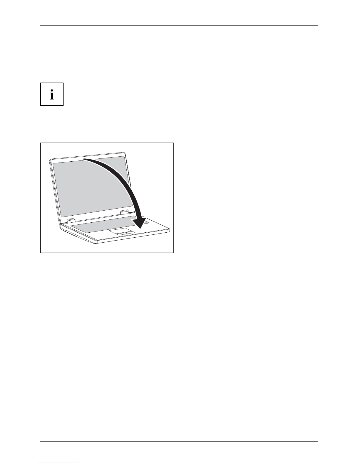
The notebo ok is delivered with a protective film inserted between
the ke yboa rd and the LCD screen.
To ensure optimal protection of the LCD screen, it is recommended
that you insert this protective film between the keyboard and the LCD
screen each time you close t he notebook.
► Close the LCD screen so that it
locks into place.
6 A26391-K245-Z220-1-7619, edition 1
Page 15

Ports and Operating Elements
Status indicators
Statusindicators
The status indicators provide informa tion about the status of the power supply,
the drives and the keyboard functions.
A 1
Power indicator
Caps Lock indicator
Battery charging i
ndicator
Scroll Lock indicator
Hard disk indicator Num Lock indicator
Radio components indicator
The meanings of t
he symbols are as follows:
Power-on indica
tor – mains operation
• Indicator light
s up green: the notebook is being powered from the m ains.
• Indicator flashes green: The notebook is in standby mode.
Power-on indic
ator – battery operation
• Indicator ligh
ts up green: the notebook is being powered from the battery.
• Indicator flashes green: the notebook is in standby mode.
•Theindicatorli
ghts up orange: the battery is nearly empty.
• Indicator flashes orange: the notebook is in standby mode and the battery
is empty.
• The indicator flas
hes yellow: the notebook is in standby mode and the battery
is almost empty.
• The indicator lights up red: the battery is flat.
StandbyindicatorPowerindicator
A26391-K245-Z220-1-7619, edition 1 7
Page 16

Ports and Operating Elements
Battery charging indicator
Indicator lights up: th e battery is charging.
BatteryindicatorBatterysymbolBatterycharging indicator
Drive indicator
Indicator lights up: one of the drives (e.g. hard disk, CD/DVD) is being accessed.
DriveindicatorIndicator
Caps Lock indicator
Indicator lights up: the Caps Lock key h
as been pressed.
All the characters you type appear in
upper case. In the case of overlay keys, the
character printed on the upper left o
f the key appears when that key is pressed.
CapsLockindicatorCapsLock
Scroll Lock indicator
Indicator lights up: the key combination
Fn
+
Rol
has been pressed.
The effect this key has varies from programme to programme.
ScrollLock:ScrollLockindicatorScroll
Num Lock indicator
Indicator lights up: the key combination
Fn
+
Num
has been pressed.
The numeric keypad is activated. In the case of overlay keys, the character printed
on the upper right of the key appears when that key is pressed.
NumLockNumLockindicator
Radio components indicator
Indicator is illuminated: The key combination
Fn
+
F1
has been pressed. One or
more radio components are switched on.
Radiocomponentsindicator
8 A26391-K245-Z220-1-7619, edition 1
Page 17

Ports and Operating Elements
Key combinations
The key combinations described below apply when using Microsoft Windows
operating systems. Some of the following key combinations may not function in
other operating systems and with some device drivers.
Key combinations are entered as follows:
► Press and hold the first key in the co m bination .
► While holding the first key down, press the other key or keys in the combination.
The key combination
Ctrl
+
Alt Gr
or
Ctrl
+
Alt
canbeusedon
external keyboards that do not not feature a
Fn
key.
Switching the radio components on/off
BluetoothBluetoothWLANWLANFn+F1
Use this key co mbination to start WirelessSelector. The radio components that
have been activated in BIOS Setup can be switched on and off individually.
The key combination
Fn
+
F1
canonlybeusediftheWirelessSelector
software is installed on your device.
Switch loudspeakers ON/OFF
Fn+F3Loudspeaker
This key combination switches your notebook’s loudspeakers off and on.
Decrease volume
Fn+F4Volume
This key combination reduces the volume of the integrated loudspeakers.
Increases volume
Fn+F5Volume
This key combination increases the volume of the integrated loudspe akers.
Switch touchpad ON/OFF
This key combination switches your notebook’s touchpad off and on.
Fn+F6TouchpadTouchpa
d
Switch camera ON/OFF
Use this key combination to switch the noteb ook’s integrated camera on or off.
Fn+F7CameraCamer
a
Decrease screen brightness
Fn+F8Screenbr ightness
This key combination decreases the brightness of the screen.
A26391-K245-Z220-1-7619, edition 1 9
Page 18

Ports and Operating Elements
Increase screen brightness
Fn+F9Screenbr ightness
This key combination increases the brightness of the screen.
To ggle output screen
Fn+F10Toggleoutputscreen
Use this key combination to select which screen(s) is/are used for display
if an external monitor is c onne cted .
You can opt to use:
• just the notebook’s LCD screen
• just the external monitor
• both the LCD screen and the external monitor
Sleep mode
ActivateenergysavingmodeFn+F12Sleepmode
Use this key combination to activate the currently configured energy saving
mode.
Switching between open applications
Use this key combination to switch between several open applications.
Alt+Tab
AltCtrl
Del
++
Performwarmreboot
This key combination restarts th
e noteboo k. First, press and hold
both the
Ctrl
and
Alt
keys, then press th
e
Del
key. First, the
Task Manager will be displayed
. You must then press all three keys
again to reboot.
Ctrl+Alt+DelWarm reboot
Back tab
This key combination moves the cu
rsor back to the previous tabular
stop.
Shift+TabBacktab
Key combinations using the Windows keys are detailed in the ma nual
for your operating system.
10 A26391-K245-Z220-1-7619, edition 1
Page 19

Ports and Operating Elements
Camera (depending on notebook model)
Your device is fittedwithaVGAcamera(1),whichcanalsobeusedasawebcam.
1
A26391-K245-Z220-1-7619, edition 1 11
Page 20
Ports and Operating Elements
Removing and installing the bat
tery
NotesBattery
Only use recharge able batteries approved by Fujitsu Technology
Solutions for your notebook.
Never u se force when inserting or removing a battery.
Make sure that no foreign bodies get into the battery connections.
Removing the battery
► Switch the notebook off and pull the power plug out of the mains socket.
Battery
► Close the LCD screen so that it locks i
nto place.
► Disconnect all cables connected to the notebook.
► Turn your notebook over and place it on
a stable, sturdy, flat surface. If necessary, lay an
anti-slip cloth on this surface to pre
vent the notebook from being scratched.
1
1
1
2
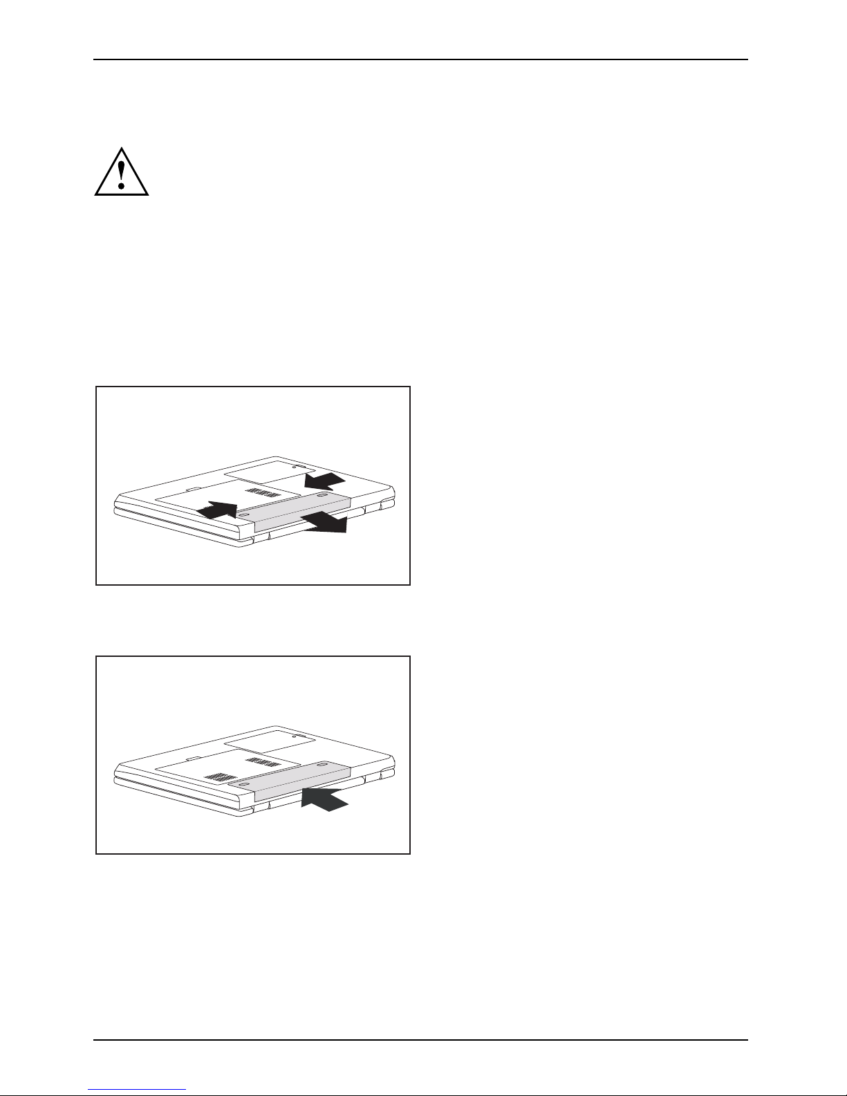
► Slide the battery lock s in the direction of the
arrow (1) as far as possible and hold in place.
► Pull the battery out of the casing i
nthe
direction of the arrow (2).
Installing the battery
1
1
1
► Push th e battery into the batt e ry
compartment until it engages (1).
Battery
12 A26391-K245-Z220-1-7619, edition 1
Page 21

Ports and Operating Elements
SIM card (depending on your computer)
Follow the instructions supplie d by the provider of the SIM card.
Inserting the SIM card
► Switch the notebook off and pull the power plug out of the mains socket.
► Close the LCD screen so that i
t noticeably locks into place.
► Disconnect all cables connected to the notebook.
► Turn your notebook over and p la
ce it on a stable, sturdy, flat surface. If necessary, lay a
non-slip cloth on this s urfac
e to prevent the notebook from being scratched.
► Remove the battery (see Section "
Removing the battery", Page 12).
1
► Insert the SIM card into the s
lot as shown
on the underside of the note
book (1). Make
sure you hear the SIM card cl
ick into place.
► Reinstall the battery (see "
Installing the battery", Page 12).
► Turn the notebook the right way up and place it on a flat surface.
► Reconnect the cables that you disconnected previously.
A26391-K245-Z220-1-7619, edition 1 13
Page 22

Ports and Operating Elements
Removing a SIM card
► Switch the notebook off and pull the power plug out of the mains socket.
► Close the LCD screen so that it locks into place.
► Disconnect all cables connected to the notebook.
► Turn your notebook over and place it on a stable, flat and clean surface. If necessary, lay
an anti-slip cloth on this surface to prevent the notebook from being scratched.
► Remove the battery (see Section "
Removing the battery", Page 12).
2
1
► Push the SIM ca rd inwards slightly to
ejectitfromtheslot(1).
► Pull the SIM card out of the slot in the
direction of the arrow (2).
► Reinstall the battery (see "
Installing the battery", Page 12).
► Turn the notebook the right way up an d place it on a flat surface.
► Reconnect the cables that you disconnected previously.
14 A26391-K245-Z220-1-7619, edition 1
Page 23

Ports and Operating Elements
Radio components: Wireless LAN/ Bluetooth/UMTS
WirelessLANBluetoothUMTS
The installation of a radio component not approved by Fujitsu Techno logy Solutions GmbH
voids the permits issued for this device (see chapter "
Technical specification", Page 23).
Depending on the device variant, wireless LAN, Bluetooth and/or UMTS may be integrated in your
notebook. On delivery, WLAN components are switch ed on, Bluetooth components off.
Switching the radio components
on and off
Start the LaunchManager using the key combination
Fn
+
F1
.
The LaunchManager enables you to switch the radio components activated in
BIOS Setup on and off individually.
WirelessLANWireless LANBluetoothBluetoothUMTSUMTS
► Press the key combination
Fn
+
F1
to start the LaunchManager.
The radio component indicator will be i
lluminated when one or more
radio components is switched on.
If you switch off the radio component
s, the Bluetooth module, UMTS and wireless
LAN transmission unit (antenna) wil
l also be switched off.
You can enable or disable the radio co
mponents individually.
BIOS Setup allows you to specify whi
ch radio components can be switched on
and off using the key combination
Fn
+
F1
.
Only those components that
have been activated in BIOS Setup c
an be switched on and off using the key
combination
Fn
+
F1
. Conversely, compo
nents that are deactivated in BIOS
setup cannot be controlled using t
he key combination.
You can also activate and deactiva
te the radio components individually in the BIOS Setup.
You must have assigned the supervi
sor password in order for this function to be available.
Pay attention to the additional s
afety notes for devices w ith radio
components provided in the "Safe
ty" manual.
Details on using W ireless LAN can
be found in the online help system
included in the Wireless LAN soft
ware.
You c a n find more inform ation on h o
w to use Bluetooth on the CD you
received with your Bluetooth sof
tware.
You can obtain more information o
n UMTS from your service provider.
A26391-K245-Z220-1-7619, edition 1 15
Page 24

Removing and installing components
during servicing
Removing and installing compo
nents
during servicing
Only qualified technicians should repair your notebook. Unauthorised
opening or incorrect repair may greatly endanger the user (electric shock,
fire risk) and will invalidate your warranty.
Components
Servicing
You m ay remove and install the compo nents described in this chapter yourself
after consulting the Hotline/Help Desk.
If you remove and install components without consulting the Hotline/Help
Desk, then the warranty of your notebook will be voided.
Notes on installing and removing boards
and components
• Switch the notebook off and pull the p ower plug out of the mains socket.
• Always remove the battery.
• Take care when you use the locking mechanisms on the battery and any other component.
• Never use sharp objects suc
h as screwdrivers, scissors or knives as leverage to remove covers.
NotesBoardESD
Boards with electrostatic sensitive devices (ESD) are marked with the label
shown.
When handling boards fitted with ESDs, you must always observe the following
points:
• You must always discharge static build up (e.g. by touching a grounded
object) before working.
• The equipment and tools you use must be free of static charges.
• Remove the power plug from the mains supply before inserting o r removing
boards containing ESDs.
• Always hold boards w ith ESDs by their edges.
• Never touch pin s or conductors on boards fitted with ESDs.
16 A26391-K245-Z220-1-7619, edition 1
Page 25

Removing and installing components
during servicing
Hard disk
The hard disk is the most important storage medium of your notebook. You can work considerably
faster and more efficiently if you copy applications and files from CDs to your hard disk.
When the hard disk is accessed, the hard disk indicator lights up in the status indicator panel.
Removing the hard disk
► Switch the notebook off and pull the power plug out of the mains socket.
Harddisk
► Close the LCD screen so that it locks into place.
► Disconnect all cables connected to the notebook.
► Turn your notebook over and place it on a stable, sturdy, flat surface. If necessary, lay an
anti-slip cloth on this surface to prevent the notebook from being scratched.
► Remove the battery (see "
Removing the battery", Page 12).
1
2
► Remove the s crew (1).
► Lift off the hard disk cover (2).
1
► Use the pulling aid to pull the hard disk out
of the bay in the direction of the arrow (1).
A26391-K245-Z220-1-7619, edition 1 17
Page 26

Removing and installing components
during servicing
Installing the hard disk
1
► Insert the hard disk into the hard
disk compartment in the direction
of the arrow (1) .
2
1
► Place the hard disk cove
roverthe
opening (1).
► Tighten the screw (2).
► Install the battery again (see "
Installing the battery", Page 12).
► Turn the notebook the right way up an d place it on a flat surface.
► Reconnect the cables that you disconnected previously.
18 A26391-K245-Z220-1-7619, edition 1
Page 27

Removing and installing components
during servicing
Removing and installing memory
modules
MainmemoryMemoryexpansionMemoryupgradeSystemexpansion
Your notebook supports dual-channel DDR2 technology.
The dual-channel DDR2 technology can only be used with two identical memo ry
modules. When two different memory modules are installed, only "single-channel"
mode is supported. This reduces the performance of your notebook.
With a memory configuration of 4 GBytes, the visible and usable main memory
may be reduced to 3 GBytes (depending on notebook configuration).
If you are asked by the Hotline/Help Desk to remove and install the memory
modules yourself, proceed as follows:
Pay attention to the relevant safety notes provided in the "Important notes" chapter.
The notebo ok must be switched off when installing/removing the memory
modules, it must not be in Suspend mode.
Only use approved memory expansion modules in your notebook (see
Section "
Technical specification", Page 23).
Never use force when installing or removing memory modules.
Make sure that foreign objects do not fall into the memory expansion compartment.
Individual components (e.g. the
processor heat sink) can become very hot
during operation. Therefore,
we reco mmend that you wait one hour after
switching off the notebook bef
ore removing or installing the memory modules.
Otherwise, there is a risk of su
ffering burns!
As some non -ESD safe component
s are exposed, please observe the s ection "
Notes
on install ing and removing boa
rds and components " , Page 16.
► Switch your notebook off and unplug the mains adapter from the mains outlet.
► Close the LCD screen so that it locks into place.
► Disconnect all cables connected to the notebook.
► Turn your notebook over and place it on a stable, flat and clean surface. If necessary, lay
an anti-slip cloth on this surface to prevent the notebo ok from being scratched.
► Remove the battery (see "
Removing the battery", Page 12).
A26391-K245-Z220-1-7619, edition 1 19
Page 28

Removing and installing components
during servicing
Removing the cover
2
1
1
1
1
1
1
► Remove the screws (1).
► Lift the cover off the notebook (2).
Removing memory modules
3
2
1
1
► Carefully push the two mounting
clips outwards (1).
MemoryexpansionMemorymodule
The memory module snaps upwards (2).
► Pull the memory module out of its slot
in the direction of the arrow (3).
Installing a m
emory module
2
a
1
► Insert the memory modu le with the contacts
and the recess (a) facing the slot (1).
Memoryex
pansion
Memorymo
dule
► Carefully push t
he memory module
downwards unti
l you feel it click
into place (2).
20 A26391-K245-Z220-1-7619, edition 1
Page 29

Removing and installing components
during servicing
Attaching the cover
1
2
2
2
2
2
2
► Place the cover in the correct
mounting position (1).
► Secure th e cover with the screws (2).
► Reinstall the battery (see "
Installing the battery", Page 12).
► Turn the notebook the right way up and place it on a flat surface.
► Reconnect the cables that you disconnected previously.
Removing and installing
the optical drive
If you are asked by the Hotline/Help Desk to remove and install the optical
drive yourself, proceed as follows:
Removing the optical drive
► Switch off your notebook and disconnect the power plug from the mains socket.
► Close the LCD screen.
► Disconnect all cables connected to the notebook.
► Turn your notebook over and place it on a firm, flat and clean surface. If necessary, lay
an anti-slip cloth on this surface to prevent the notebo ok from being scratched.
► Remove the battery (see Chapter "
Removing the battery", Page 12).
Harddisk
2
1
► Remove the s crew (1).
► Press a metal pin or wire (e.g. p aperclip)
firmly into the o pening (2).
The drive tray will be ejected. You can now
pull out the drive tray completely.
► Hold the drive tray firmly on both sides in the centre, and carefully pull
the op tical drive out of the notebook.
► Push in the drive tray until you feel it lock into place.
A26391-K245-Z220-1-7619, edition 1 21
Page 30

Removing and installing components
during servicing
Installing the optical drive
2
1
► Slide the drive into the notebook in the
direction of the arrow (1).
► Tighten the screw (2).
► Reinstall the battery (see "
Installing the battery", Page 12).
► Turn the notebook the right way up an d place it on a flat surface.
► Reconnect the cables that you disconnected previously.
22 A26391-K245-Z220-1-7619, edition 1
Page 31

Techn ical specification
Technical specification
Notebook
Technicalspecification
Environmental conditions
Environmental class 3K2
Temperature
Operating (3K2) 5 °C – 35 °C
Transportation (2K2) - 15 °C – 60 °C
Dimensions
Width x Depth x Height (front/back)
360 mm x 260 mm x 39-42 mm
Weight (depending on configuration)
Approx. 2.8 kg
The data sheet for this notebook contains further technical dat a. The data
sheet can be found on your notebook or on the Internet at "
http://ts.fujitsu.com"
or on the "Drivers & Utilities" CD/DVD.
Battery
Technicalspecification
6-cell rechargeable battery 6-cell rechargeable battery
Rated voltage 11.1 V 11.1 V
Rated capacity 4400 mAh 5200 mAh
The operating time depends on the device configuration, the active
applications and the energy saving settings.
A26391-K245-Z220-1-7619, edition 1 23
Page 32

Tech nical specification
Mains adapter
Mains adapter (65W)
Technicaldata
Use the 65W mains adapter for the following processors: CXXX, PXXX, T1XXX.
Electrical data
Rated voltage 20 V
Max. rated cu rrent 3.25 A
Mains adapter (90W)
Use the 90W mains adapter for the following processors: T3XXX, T5XXX, T9XXX.
Electrical data
Rated voltage 20 V
Max. rated current 4.5 A
An additional mains adapter
or power cable can be ordered at any time.
24 A26391-K245-Z220-1-7619, edition 1
Page 33

Index
Index
A
Activate energy saving mode 10
Alt + Tab 10
B
Back tab 10
Battery 4
important notes 12
inserting 12
removing 12
Battery charging indicator 8
Battery indicator
see battery indicator 8
Battery release latch 4
Battery symbol
see battery indicator 8
Bluetooth 15
switching off 9, 15
switching on 9, 15
Board 16
C
Camera 4
switching off 9
switching on 9
Caps Lock
indicator 8
Caps Lock indicator 8
Components
installing / removing 16
Ctrl+Alt+Del 10
D
DC input connector (DC IN) 4
Drive indicator 8
E
ESD 16
ExpressCard s lot 4
F
Fn + F1 9
Fn + F10 10
Fn + F12 10
Fn + F3 9
Fn + F4 9
Fn + F5 9
Fn + F6 9
Fn + F7 9
Fn + F8 9
Fn + F9 10
H
Hard disk 4
removing 17, 21
Headphones port/Line Out 4
I
Indicator
Drive 8
K
Kensington Lock 4
L
LAN port 4
Loudspeaker
switching ON/OFF 9
Loudspeakers 4
M
Main memory 19
Memory expansion 19
installing 20
removing 20
Memory module
installing 20
removing 20
Memory upgrade 19
Modem port 4
Monitor port (VGA) 4
N
Notes
battery 12
boards 16
Num L ock
indicator 8
Num Lock indicator 8
O
ON/OFF switch 4
Optical drive 4
A26391-K245-Z220-1-7619, edition 1 25
Page 34

Index
P
Power indicator 7
R
Radio component s indicator 8
S
Screen brightness
decrease 9
increase 10
Scroll
indicator 8
Scroll Lock indicator 8
Scroll Lock:
indicator 8
Servicing 16
Shift + Tab 10
Sleep mode
activating 10
Standby indicator 7
Status indicators 4, 7
System expansion
memory expansion 19
T
Technical data
Mains adapter 24
Technical specification
battery 23
notebook 2 3
Toggle output screen 10
Touchpad 4
switching off 9
switching on 9
Touchpad buttons 4
U
UMTS 15
switching off 15
switching on 15
USB port 4
V
Volume
decrease 9
increase 9
W
Warm reboot 10
Wireless LAN 15
switching off 15
switching on 15
WLAN
switching off 9
switching on 9
26 A26391-K245-Z220-1-7619, edition 1
 Loading...