

Page 1

ESPRIMO Mobile Series
CELSIUS H
EasyGuide
Page 2

Are there ...
... any technical problems or other questions that you would like help with?
Please contact:
• our Hotline/Help Desk (refer to the enclosed Help Desk List or go to:
"
http://ts.fujitsu.com/helpdesk")
• your sales partner
• your sales office
Additional information is contained in the Help Desk list and the "Warranty" manual. The
"Warranty" manual can be found on the supplied "Drivers & Utilities" CD/DVD.
The latest information about our products, useful tips, updates etc. is available
from our website: "
http://ts.fujitsu.com"
Page 3

Page 4

Published by
Fujitsu Technology Solutions GmbH
A26391-K260-Z220-1-7619, Edition 1
2009/04
Produced by
XEROX Global Services
Page 5

ESPRIMO Mobile Series / CELSIUS H
Innovative technology... 1
Important notes
3
Ports and operati
ng elements
4
Removing and installing components
during servicing
27
Technical dat
a
34
Index
36
EasyGuide
Page 6

Adobe and Acrobat are trademarks of Adobe Systems Incorporated and may
be protected in certain countries.
The Bluetooth trademarks are the property of Bluetooth SIG, Inc., U.S.A. licensed
for Fujitsu Technology Solutio ns GmbH.
Intel is a registered trademark, Core is a trademark of Intel Corporation, USA.
Kensington and MicroSaver are registered trademarks of ACCO World Corporation.
Microsoft, MS Windows and Windows Vista are registered trademarks of the Microsoft Corporation.
All other trademarks referenced are trademarks or registered trademarks of their
respective owners, whose protected rights are acknowledged.
Copyright © Fujitsu Technology Solutions G mbH 2009
All rights reserved, including rights of translation, reproduction by printing, copying
or similar methods, in part or in whole.
In the event of violations, perpetrators will be liable to prosecution for damages.
All rights reserved, including rights created by patent grant or registration of a utility model or design.
Subject to availability and technical m odifications.
Page 7

Contents
Contents
Innovativetechnology... ................................................................ 1
Notational conventions .................................................................. 2
Importantnotes ........................................................................ 3
Help ifproblemsoccur ................................................................... 3
Ports andoperatingelements .......................................................... 4
ESPRIMO MobileU Series .............................................................. 4
ESPRIMO MobileM Series .............................................................. 6
ESPRIMO MobileD Series ESPRIMO MobileX Series CELSIUS HSeries .................. 9
Switching on the notebook . . . ........................................................... 11
Switching off the notebook . . . . ........................................................... 12
Status indicator ......................................................................... 13
Keycombinations ....................................................................... 15
Application buttons ...................................................................... 17
Programming the application keys .................................................... 18
Camera (optional) . ...................................................................... 18
Module/module bay . . . .................................................................. 19
Removing a module . . . . . . ........................................................... 19
Installing a module .................................................................. 20
Removing andinstalling thebattery ....................................................... 20
Removing the battery ................................................................ 20
Inserting the battery ................................................................. 21
SIM card ............................................................................... 22
Inserting the SIMcard ............................................................... 22
Removing aSIM card ............................................................... 23
Radio components: Wireless LAN/Blueto oth/UMT S ........................................ 24
Switching the wireless components on and off . ........................................ 24
Security functions ....................................................................... 25
Brief overview ofsecurityfunctions ................................................... 26
Removing a
nd installing compon ents during servicing . . .. .............................
27
Notes on in
stalling and removing boards andcomponents ..................................
27
Removing
the cover .....................................................................
28
Devices w
ith ajoint compartmentfor memory andhard disk ............................
28
Devices w
ith separate compartments for memory and hard disk .........................
28
Attachi
ngthe cover .....................................................................
29
Devices
with ajoint compartmentfor memory andhard disk ............................
29
Devices
with separate compartments for memory and hard disk .........................
29
Removi
ngand installingthe hard disk ....................................................
30
Removi
ngthehard disk ..............................................................
30
Insta
lling theharddisk ...............................................................
31
Remov
ing andinstalling memorymodules ................................................
32
Remov
ing memorymodules ..........................................................
32
Inst
alling amemorymodule ..........................................................
33
Technicaldata ......................................................................... 34
Notebook . . ............................................................................. 34
Main battery/expansion battery ........................................................... 34
Power adapter .......................................................................... 35
CELSIUS H:Mains adapter (120 W) .................................................. 35
ESPRIMO Mobile Series: Mains adapter (90 W) . . . .................................... 35
A26391-K260-Z220-1-7619, edition 1
Page 8

Contents
Index .................................................................................. 36
A26391-K260-Z220-1-7619, edition 1
Page 9

Innovative tech nology...
Innovative technology...
…and an ergonomic design make your notebook a reliable, convenient mobile PC.
Your notebook is available in several different versions. Most of the sections in this manual
apply to a ll models – any differences are indicated separately. Some of the illustrations and
features in this manual may differ from your model and are for guidance only.
Your Windows operating syst em is already pre-installed and optimally configured. This means
you’re ready to start when you switch on your notebook for the first time.
Your notebook features the very latest technology so that you get the best performance from your
computing experience. Depending on the model, the following components may be included:
• up to 8 GBytes of main memory (DDR3 RAM).
• a CD/DVD burner drive for watching DVD movies and writing your own CDs and DVDs
• an integral camera for snapshots and video chat
• several USB ports, providing simple expansion options for game pads, printers and more
• LAN, wireless LAN and Bluetooth for Internet and network access
• UMTS/3G functionality which provides wireless access to your data while you are
out and about (depending on network availability)
• a SIM card slot that can be used to operate a SIM card for UMTS (depending on model)
• A module bay suitable for housing the following modules: a second battery, a
second hard disk drive or an empty insert (weight saver)
• a Port Replicator port
• a memory card slot for transferring digital photos, music and videos quickly onto your notebook
• an ExpressCard slot for operating an ExpressCard/34 or ExpressCard/54 (depending on model)
• a SmartCard reader to protect your notebook from un authorised access
• a touchpad and an additional TouchStick
• an combined eSATA/USB port for connecting an extern al SATA hard disk
• an integrated audio controller and two stereo speakers. You can even c onnect a
microphone and external speakers for even better sound performance.
• a shock sensor for protecting the hard disk
With the user-friendly BIOS-Setup you can control the hardware of your notebook and improve the
protection of your system against unauthorised access by using the powerful passw ord features.
This Operating Manual tells you how to get your notebook up and running
and how to operate it in daily use.
Further information on this notebook can be found in the following documentation:
• in the "Professional Note book" Operating Manual
• in the "Safety" and " Warranty" manuals
• in the do cume ntation for the operating system
• in information files (e.g. *.TXT, *.DOC, *.WRI, *.HLP, *.PDF)
You c an find information on accessories for your n otebook at
"
http://ts.fujitsu.com/accessories".
A26391-K260-Z220-1-7619, edition 1 1
Page 10

Innovative t echnology...
Notational conventions
Pay particular attention to text marked with this symbol. Failure to observe
these warnings could pose a risk to health, damage the device or lead
to loss of data. The w arra nty will be invalidated if the device becomes
defective through failure to observe these warnings.
Indicates important informat
ion for the proper use of the device.
►
Indicates an activity that must be performed
Indicates a result
This font
indicates data entered usin
g the keyboard in a program dialogue or
command line, e.g. your pass
word ((Name123) or a command used to
start a program (start.ex
e)
This font
indicates information that is displayed on the screen by a program, e.g.:
Installation is complete.
This font
indicates
• terms and texts used in a software interface, e.g.: Click on Save
• names of programs or files, e.g. Windows or setup.exe.
"This f ont"
indicates
• cross-references to another section, e.g. "Safety information"
• cross-references to an external source, e.g . a web address: For more
information, go to "http://ts.fujitsu.com"
• Names of CDs, DVDs and titles or designations of other materials, e.g.:
"CD/DVD Drivers & Utilities" or "Safety" Manual
Abc
indicates a key on the keyboard, e.g:
F10
This font
indicates terms and texts that are emphasised or highlighted, e.g.: Do
not switch off the d evice
2 A26391-K260-Z220-1-7619, edition 1
Page 11

Important notes
Important notes
Take note of the safety hints provided in the "Safety" m anual, in the "Professional
Notebook" operating manual and in this manual.
Help if problems occur
Should you ever have a problem with your computer that you cannot solve yourself, in many cases
you can solve it quickly using the SystemDiagnostics prog ram pre-installed on your comput er.
► To start the SystemDiagnostics programme, click on Startsymbol - Program -
Fujitsu Siemens Computers - SystemDiagnostics
or
► To s t a rt t h e SystemDiagnostics progra mme, click on Startsymbol - Program
- Fujitsu - SystemDiagnostics.
► If a problem is detected du
ring the test run, the System Diagnostics program outputs
a code (e.g. DIFS c ode YXXX
123456789123).
► Take a note of this DIFS code and the ID number of your device. The ID number can
be found on the type rating plate on the back of the casing.
► For further clarification o
f the problem, contact the Help Desk for your country (see the
Help Desk list or visit the
Internet at "
http://ts.fujitsu.com/support"). For this, please have
ready the ID number & seri
al number of your system and the DIFS code.
A26391-K260-Z220-1-7619, edition 1 3
Page 12

Ports and operating elements
Ports and operating elements
This chapter presents the individual hardware components. This will pro vide you with an
overview of the ports and operating elements on the notebook.
Please familiarise yourself w ith these components before you start working with y our notebook.
ESPRIMO Mobile U Series
1
2
4
17
14
15
12
11
8
18
9
19
21
22
20
23
25
24
6
5
3
16
13
4
7
26
10
1 = WebCam (optional)
2 = ON/OFF switch
3 = Application b uttons
4 = Loudspeaker
5 = Touchpad
6 = Touchpad buttons
7 = Fingerprint sensor (ESPRIMO
Mobile U9215)
8 = Memory card slot
9 = ON/OFF switch for wireless c omponents
10 = Additional power-on indicator (LED)
11 = M icro phone port
12 = Headphone port
13 = SmartCard reader
14 = USB port
15 = Kensington Lock
16 = Status indicator
17 = Module bay
4 A26391-K260-Z220-1-7619, edition 1
Page 13

Ports and operating elements
18 = Modem connection (optional)
19 = Combined eSATA/USB port*
20 = LAN port
21 = VGA mo nitor port
22 = USB port
23 = DC input connector (DC IN)
24 = Service compartment for memory
and hard disk
25 = Battery
26 = Port for port replicator
* Yo u can use the combined eSATA/USB port to connect either a n eSATA connector or
a USB connector. This port can take higher currents (max. 1 A).
A26391-K260-Z220-1-7619, edition 1 5
Page 14
Ports and operating elements
ESPRIMO Mobile M Series
1
2
4
19
15
16
13
12
9
20
10
25
21
23
22
24
27
26
7
6
5
3
14
17
4
8
28
18
11
1 = WebCam (opt
ional)
2 = ON/OFF switch
3 = Applicati
on buttons
4 = Loudspeaker
5 = TouchSti
ck keys
6 = Touchpad
7 = Touchpa
d buttons
8 = Fingerprint sensor (ESPRIMO
Mobile M9415)
9 = Memory
card slot
10 = ON/OFF switch for wireless co mponents
11 = Addit
ional pow er-on indicator (LED)
12 = Microphone port
13 = Head
phone port
14 = ExpressCard slot
15 = Combined eS
ATA/USB port*
16 = Kensington Lock
17 = Status ind
icator
18 = SmartCard reader
19 = Module ba
y
20 = Modem connection (optional)
21 = LAN port
22 = VGA monitor port
23 = USB por
ts
24 = DC input connector ( DC IN)
25 = Servi
ce compartment for the hard disk
26 = Service compartment for t he memory
27 = Batt
ery
28 = Port for port replicator
6 A26391-K260-Z220-1-7619, edition 1
Page 15

Ports and operating elements
* Yo u can use the combined eSATA/USB port to connect either a n eSATA connector or
a USB connector. This port can take higher currents (max. 1 A).
A26391-K260-Z220-1-7619, edition 1 7
Page 16

Ports and operating elements
8 A26391-K260-Z220-1-7619, edition 1
Page 17

Ports and operating elements
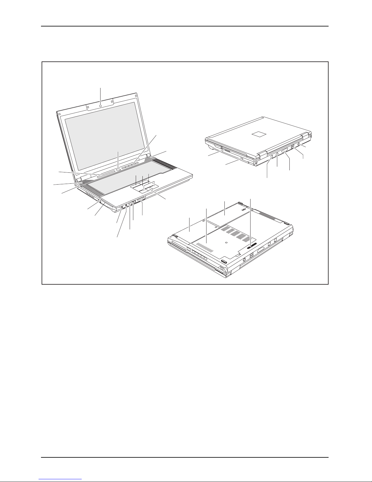
ESPRIMO Mobile D Series
ESPRIMO Mobile X Series
CELSIUS H Series
1
2
4
21
22
17
18
19
14
13
9
25
24
26
23
11
10
31
27
29
28
30
33
32
7
6
5
3
15
16
20
8
34
4
12
1 = WebCam (optional)
2 = ON/OFF switch
3 = Application buttons
4 = Loudspeaker
5 = TouchStick keys
6 = Touchpad
7 = Touchpad buttons
8 = Fingerprint sensor (ESPRIMO Mobile
D9510 / D9515 and CELSIUS
H265 / H270)
9 = Memory card slot
10 = Infrared interface (CELSIUS only)
11 = ON/OFF switch for wireless components
12 = Additional power-on indicator ( LED)
13 = Microphone port
14 = Headphone port
15 = ExpressCard slot
16 = PC card slot
17 = Combined eSATA/USB port*
18 = FireWire port
19 = Kensington Lock
20 = Status indicator
21 = SmartCard reader
22 = Module bay
23 = DC input connector (DC IN)
24 = Modem connection (optional)
A26391-K260-Z220-1-7619, edition 1 9
Page 18

Ports and operating elements
25 = USB port
26 = Serial port
27 = Parallel port
28 = VGA monitor port or DVI monitor
port (device-dependent)
29 = LAN port
30 = USB ports
31 = Service compartment for the hard disk
32 = Service compartment for t he memory
33 = Battery
34 = Port for port replicator
* You can use the combined eSATA/USB port to connect either an eSATA connector or
a USB connector. This port can take higher currents (max. 1 A).
10 A26391-K260-Z220-1-7619, edition 1
Page 19

Ports and operating elements
Switching on the notebook
Before you operate yo ur new notebook for the first time using the battery, you
should charge the battery fully. Please note that charging the battery for the first
time can take much more time than subsequent charges.
1
► Lift up the LCD screen (1).
1
► Press the ON/OFF switch (1) to switch
the notebook on.
The operatin g mode i
ndicator of
the notebook appear
s in the status
indicator panel.
Windows XP:
You ca n c onfigure the on/off button under Start - (Settings) - Control Panel Performance and Maintenance - Power Options - Advanced.
Windows Vista:
You can c o nfigure the on/off button under Start - (Settings) - Control
Panel - Mobile PC - Power Options.
If you have assigned a password, yo u must enter this when requested in order
to start the operating system. Further information can be found in the "Security
functions" section of the "Professional Notebook" operating manual.
A26391-K260-Z220-1-7619, edition 1 11
Page 20

Ports and operating elements
Switching off the notebook
► Close all applications an d shut dow n your operating system (please refer
to the manual for the operating system).
If the notebook cannot be shut down properly, press and hold the ON/O FF
button for approximately four seconds. The notebook will switch off. However,
any unsaved data may be lost in the process.
► Close the LCD screen.
12 A26391-K260-Z220-1-7619, edition 1
Page 21

Ports and operating elements
Status indicator
Statusindicator
The status indicator panel is a small LCD panel on which various sym bols appear. These symbols
provide information about the status of the power supply, the drives and the keyboard functions.
EC
PC
MEM
Power-on indicator Wireless components indicator
Power indicator
CD/DVD/BD/hard disk indicator
Battery charging indicator
EC
PC
MEM
PC card/ExpressCa
rd/memory card
indicators
First ba ttery indicator Num Lock indicator
Second battery in
dicator
Caps Lo ck indicat
or
A26391-K260-Z220-1-7619, edition 1 13
Page 22

Ports and operating elements
The meanings of the symbols are as follows:
Power-on indicator
Power-onindicatorIndicator
• Indicator is on: The notebook is switched on.
• The indicator flashes (1 second on / 1 second off): The notebook is in po wer
saving mode.
• The indicator is not illuminated: The notebook is switched off.
Power indicator
PowerindicatorIndicator
Indicator is on: the mains adapter is supplying power to the notebook.
Battery charging indicator
BatterychargingindicatorIndicator
• Indicator is on: The battery is not being charged/has reached more than 90% of
its maximum charge, or the battery is being charged.
• The indicator is not illuminated: The battery is faulty.
Battery indicators
IndicatorIndicatorBattery
The charging state of the bat teries is shown by two battery indicators. 1 indicates
that the information applies to the fi rst battery in the battery compartment. 2
indicates that the information applies to the second battery in the module bay.
indicates that the battery is charged to 0 - 20 % of its maximum capacity.
indicates that the battery is charged to 20 - 40 % of its maximum capacity.
indicates that the battery is charged to 40 - 60 % of its maximum capacity.
indicates that the battery is charged to 60 - 80 % of its maximum capacity.
indicates that the battery is charged to 80 - 100 % of its maximum capacity.
Wireless components indicator
IndicatorIndicatorBluetoothIndicatorWirelessLAN
• Indicator is on: One or more wireless components are switched on.
CD/DVD/BD/hard disk indicator
IndicatorCD/DVDindi
cator
Harddiskin
dicator
IndicatorIndicator
• Indicator is on: The hard disk drive of the notebook is being accessed.
• Indicator is on: The CD/DVD/BD in the optical drive
is being accessed. You
must not remove the CD/DVD/BD when the indicator li
ght is on.
EC
PC
MEM
PC card/ExpressCard /mem ory card indicators
IndicatorIndicatorPCCardExpressCardMemorycard
Indicator is on: A PC card, ExpressCard or memory card is being accessed.
Num Lock indicator
IndicatorNumLock
Indicator is on: the
Num
key has been pressed. The v irtu
al numerical keypad is
activated. You can output the chara cters indicate
d on the upper right of the keys.
Caps Lock indicator
Indic
ator
CapsL
ock
Indicator is on: The Caps Lock key has been pressed. All the characters you type
will appear in upper case. In the case of overlay keys, the character printed on the
upper left of the key will appear when that key is pressed.
14 A26391-K260-Z220-1-7619, edition 1
Page 23

Ports and operating elements
Key combinations
The key combinations described below apply when using Microsoft Windows
operating systems. Some of the following key combinations may not function in
other operating systems or with certain device drivers.
Key combinations are entered as follows:
► Press and hold the first key in the combination.
► While holding the first key d own, press the other key or keys in the combination.
The key combination
Ctrl
+
Alt Gr
or
Ctrl
+
Alt
canbeusedon
external keyboards that do not not feature a
Fn
key.
Switching t he wireless components on/off
BluetoothBluetoothWLANWLANFn+F1
This key combination is used to start the WirelessSelector software. With the
aid o f this software you can individually switch the wireless components
activatedintheBIOS Setup on and off.
Switch loudspeakers ON/OFF
Fn+F3Loudspeaker
This key combination switches th e loudspeakers of your notebook off and on.
Decrease volume
Fn+F4Volume
This key combination reduces the volume of the integrated loudspeakers.
Increase volume
Fn+F5Volume
This key combination increases the volume of the integrated loudspe akers.
Switch touchpad ON/OFF
This key combination switches your notebook’s touchpad on and off.
Fn+F6TouchpadTouchpad
Switch camera ON/OFF (th is function is only available on certain
devices)
Use this key combination to switch the noteb ook’s integrated camera on or off.
Fn+F7CameraCamera
Decrease screen brightness
Fn+F8Screen
brightness
This key combination decreases the brightness of the screen.
Increase screen brightness
Fn+F9Scree
nbrightness
This key combination increases the brightness of the screen.
A26391-K260-Z220-1-7619, edition 1 15
Page 24

Ports and operating elements
Toggle output screen
Fn+F10Toggleoutputscreen
Use this key combination to select which screen(s) is/are used for display
if an external monitor is c onne cted .
You can opt to use:
• just the notebook’s LCD screen
• just the external monitor
• both the LCD screen and the external monitor at the same time
Fan Control
FanControl
This key combination starts the "Fan Control" program. W ith this programme,
you can configure the performance of the processo r and the fan.
Sleep mode
SleepmodeFn+F12
With this function you can activate the Sleep mode.
Switch between open app lications
Use this key combination to switch between several open applications.
Alt+Tab
AltCtrl
Del
++
Performwarmreboot
This key combination restarts th
e noteboo k. First, press and hold
both the
Ctrl
and
Alt
keys, then press th
e
Del
key.Firstofall
the Task Manager will be displa
yed. You must th en press all three
keys again to r eboot.
Ctrl+Alt+DelRestart
Back tab
This key combination moves the cu
rsor back to the previous tab stop.
Shift+TabBacktab
Key combinations using the Windows keys are detailed in the ma nual
for your operating system.
16 A26391-K260-Z220-1-7619, edition 1
Page 25

Ports and operating elements
Application buttons
Applicationbuttons
Your note book is equipped with five application keys.
Lock Workstation k
ey
This key allows you
to lock your workstation. You can also configure this key as desired.
Mobility Center key
Under Windows Vista, this button is used to start the Mobility Center. You can also
configure this key as desired.
I key
You can use the I key to start the Fujitsu Launch C enter and obtain further information
on your computer. You can also configure this key as you wish.
E key
The E key is a simple way of activating and deactivating power management functions
(e.g. reducing the screen brightness), refer to the "Professional Notebook" manual.
Wireless Compone
nts key
This application
keyisusedtostarttheWirelessSelector softw are. The wireless
components that h
ave been activated in the BIOS Setup can be switched on and off
individually.
A26391-K260-Z220-1-7619, edition 1 17
Page 26

Ports and operating elements
Programming the application keys
With the Application Button Utility software you can assign various functions to the application keys.
Windows XP (32-bit):
You wi l l find the Application Button Utility software under Start - All Programs - Fujitsu
- Mobile Software Suite - Application Button Utility.
Windows Vista:
You wi l l find the Application Button Utility software under Start symbol - All Programs Fujitsu - Mobile Software Suite - Application Button Utility.
► Program the application keys according to your requirem ents.
Camera (optional)
Your device is fitted with a VGA camera (1), which can also be use d as a webcam.
1
Further information on the use of the camera is available with the supplied software.
If you do not want the camera function, you can disable it in the BIOS.
18 A26391-K260-Z220-1-7619, edition 1
Page 27

Ports and operating elements
Module/module bay
ModulebayModulesDVD-ROMdriveSecondharddiskCD-ROM driveSecondbatteryWeightsaverBlankinsert,see weightsaverSuper-Multi-FormatDVDdriveDVD+/-R/RWdrive
Fujitsu Technology Solutions currently offers the following modules:
• Optical drive
• Expansion battery
• Weight saver
• ExpressCard insert (only for ESPRIMO Mobile U9210/ESPRIMO Mobile U9215)
•fully-fledged second SATA hard disk (outside the module bay you can also use the
hard disk insert as a USB hard disk drive for other notebooks).
Only use modules designed for your notebook.
Do not use force when installing or removing the module.
Make sure that no foreign objects enter the module bay.
You can swa p modules during operation. Thi
s means you do not
need to switch off the notebook.
To replace a module, simply click on the cor
responding icon in the
task bar and then on Exit or Select - Exit.
The module can now be removed without any fu
rther actions being necessa ry.
Removing a module
ModuleDriveSecondba tteryWeightSaver
► Place the notebook on a flat surface.
Use the corresponding icon in the task bar to stop the module:
► Left-click on the icon.
► Select the module you w ant to stop and re move.
► Press the Enter key.
Wait for the dialogue box which tells you that it is now safe to remove the module.
3
2
1
► Fold the module lever in the direction of
the arrow (1) and hold it in place.
► Pull the module lever in the direction
of the arrow (2).
The module is unlocked.
► Carefully pull the modem out of
the notebook (3).
A26391-K260-Z220-1-7619, edition 1 19
Page 28

Ports and operating elements
Installing a module
1
► Slide module in the direction of the arrow into
the notebook (1) until it noticeably engages.
Removing and installing the battery
NotesBattery
Only use recharge able ba
tteries approve d by Fujitsu Technology
Solutions for your note
book.
Never use force when inse
rting or removing a battery.
Make sure that no foreign
bodies get into the battery connections.
The illustrations shown below may differ from your actual device. They are
merely intended to clarify the principles involved.
Removing the battery
► Switch the notebook off and pull the power plug out of t he mains socket.
Battery
► Close the LCD screen.
► Disconnect all cables connected to the notebook.
► Turn your notebook over and place it on a stable, sturdy, flat surface. If necessary, lay an
anti-slip cloth on this surface to prevent the notebook from being scratched.
2
3
1
► Push the battery lock in the direction of
the arrow (1) as far as it will go.
► Slide the locking device in the direction of
the arrow (2) and hold it in place.
► Remove the battery from the notebook
in the direction of the arrow (3).
20 A26391-K260-Z220-1-7619, edition 1
Page 29

Ports and operating elements
Inserting the battery
1
2
► Place the battery in the battery compartment
so that the contacts enter first (1).
Battery
► Push the battery into the battery
compartment until you feel it click into place.
► Push the battery lock in the direction of
the arrow (2) up to the stop.
A26391-K260-Z220-1-7619, edition 1 21
Page 30

Ports and operating elements
SIM card
Follow the instructions supplied by the provider of the SIM card.
The SIM card slot is located in the battery compartment. It can only
be accessed by taking out the battery.
Inserting the SIM card
► Switch the notebook off and pull the power plug out of t he mains socket.
► Close the LCD screen.
► Disconnect all cables connected to the notebook.
► Turn your notebook over and place it on a stable, sturdy, flat surface. If ne cessary, lay a
non-slip cloth on this surface to prevent the notebook from being scratched.
► Remove the battery (see S ection "
Removing the battery", Page 20).
1
► Slide the SIM card forwards into its slot
as shown in the battery compartment
(1). Make sure that the SIM card
noticeably engages in place.
► Reinstall the battery (see "
Inserting the battery", Page 21).
► Turn the notebook the right way up and place it on a flat surface.
► Reconnect the cables that you disconnected previously.
22 A26391-K260-Z220-1-7619, edition 1
Page 31

Ports and operating elements
Removing a SIM card
► Switch the notebook off and pull the power plug out of the mains socket.
► Close the LCD screen.
► Disconnect all cables connected to the notebook.
► Turn your notebook over and place it on a stable, flat and clean surface. If necessary, lay
an anti-slip cloth on this surface to prevent the notebo ok from being scratched.
► Remove the battery (see Section "
Removing the battery", Page 20).
2
1
► Push the SIM card inwards slightly to
eject it from the slot (1).
► Pull the SIM card out of the slot in the
direction of the arrow (2).
► Reinstall the battery (see "
Inserting the battery", Page 21).
► Turn the notebook the right way up and place it on a flat surface.
► Reconnect the cables that you disconnected previously.
A26391-K260-Z220-1-7619, edition 1 23
Page 32

Ports and operating elements
Radio components: Wireless LA N/B luetooth/UMTS
WirelessLANBluetoothUMTS
The installation of a radio component not approved by Fujitsu Technology Solutions GmbH
voids the permits issued for this device (see chapter "
Technical data", Page 34).
Switching the wireless compone
nts on and off
Start the WirelessSelector using the application key for the wireless components
or the k ey combination
Fn
+
F1
.
The Wireless Selector software m ust already be installed.
With the WirelessSelector you can individually switch the wireless components
activated in BIOS Setup on or off.
WirelessLANWireless LANBluetoothBluetoothUMTSUMTS
► Press the application key for the wireless components to start the WirelessSelector.
or
► Press the key combination
Fn
+
F1
to start the WirelessSelector.
The wireless component indicator will come on when one or more wireless
components are switched on.
If you switch off the wireless com ponents, the Bluetooth module, UMTS/3G and
wireless LAN transmission unit (antenna) will also be switched off.
You can enable or disable the wireless components individually.
BIOS Setup allows you to specify which wireless components can be switched on and off
using the application key or the key combination
Fn
+
F1
. Only components which
have been activated in BIOS Setup can be switched on and off using the application key
or the key combination
Fn
+
F1
. Conversely, compone nts which are deactiva ted in
the BIOS setup cannot be controlled u sing the application key or the key combination.
You can also act ivate and deactivate the wireless components
individually in the BIOS Setup.
Pay attention to the additional safety notes for devices with wireless
components provided in the "Safety" manual.
Details on using Wireless LAN can be found in the online help system
included with the Wireless LAN software.
More detailed information on how to use Bluetooth can be found on
the " Drivers & Utilities"CD/DVD.
You can obtain more information on UMTS/3G from your service provider.
24 A26391-K260-Z220-1-7619, edition 1
Page 33

Ports and operating elements
Security functions
Securityfunctions
Your device enables you to protect your system and personal data in a number
of ways against unauthorised access. By combining these options, you can
achieve maximum protection for your syste m.
Bear in mind that improper use of security functions will mean that you will also be unable
to access your system and your data. Therefore, please note the following information:
• Back up your data on external data carriers at regular intervals.
• You will need to assign passwords for some of the security functions.
Please be sure to remember these passwords, as otherwise you will
no longer be able to access your system.
We recommend that you make a note of the passwords and keep them in a safe place.
If you lose both the user and the admin passwords you will need to contact
the help desk. The telephone numbers can b e found on the supplied Help
Desk list or on our website at "
http://ts.fujitsu.com/support/".Theservice
of deleting passwords is not covered by your warranty, and a charg e will
therefore be made for any assistance provided.
A26391-K260-Z220-1-7619, edition 1 25
Page 34

Ports and operating elements
Brief overview of security functions
BriefoverviewofthesecurityfunctionsSecurityfunctions
Detailed information about the security equipment of your device can be fo und
in the "Professional Notebook" manual, on the "Drivers & Utilities" CD/DVD
or on the Internet under "
http://ts.fujitsu.com/support".
Security fu nctions Type of protection
Preparation
Kensington Lock Mechanical Fitting and locking the
Kensington MicroSaver
(accessory)
Fingerprint sensor
(device-dependent)
Biometric Installing the supplied
fingerprint software
BIOS password protection Password protection f or BIOS
Setup, operating system and
hard disk with supervisor and
user password. The passwords
consist of a maximum of eight
alphanumeric characters.
Specify at least one supervisor
password in the BIOS Setup
and act ivate the password
protection for the operating
system and hard disk a s
desired.
Boot from Removable Media
Prevents unauthorised booting
of an operating system from
external media (e.g. USB stick,
USB CD-ROM drive etc.)
In the BIOS Setup, go to the
Security menu and edit the
option Boot from Removable
Media.
System Lock 2 The B IO S can only be called up
with a SmartCard and PIN.
Assign a supervisor password
in the BIOS and initialise the
SmartCard.
SmartCard reader PIN and SmartCard protection
for operating system
Install the corresponding
software, e.g. SmartCase
Logon+ (accessory). Specify
a password when using the
SmartCase Logon+ software.
Trusted Platform Module
(optional)
Identification and authentication
of the notebook
Defining a supervisor password
in the BIOS Setup and enabling
the TPM (Security Chip)
26 A26391-K260-Z220-1-7619, edition 1
Page 35

Removing and installing components
during servicing
Removing and installing compo
nents
during servicing
Only qualified technicians should repair your notebook. Unauthorised
opening or incorrect repair may greatly endanger the user (electric shock,
fire risk) and will invalidate your warranty.
Components
Servicing
You may remove and install the components described in this chapter yourself
after consulting the Hotline/Help Desk.
If you remove and install components without consulting the Hotline/Help
Desk, t hen the warranty of your notebook will be voided.
The illustrations shown below may differ f rom your actual device. They are
merely intended to clarify the principles involved.
Notes on installing and removing boards
and components
• Switch the notebook off and pull the power plug out of the mains socket.
• Always remove the batter
y.
• Take care when you use the locking me cha nisms on the battery and any other component.
• Never use sharp objects su
ch as screwdrivers, scissors or knives as leverage to remove covers.
NotesBoardESD
Boards with electrostatic sensitive devices (ESD) are marked with the label
shown.
When handling boards fitted with ESDs, you must always observe the following
points:
• You must always discharge static build up (e.g. by touching a grounded
object) before working.
• The equipment and tools you use must be free of static charges.
• Remove the power plug from the mains supply before inserting or removing
boards containing ESDs.
• Always hold boards with ESDs by their edges.
• Never touch pins or conductors on boards fitted with ESDs.
A26391-K260-Z220-1-7619, edition 1 27
Page 36

Removing and installing components
during servicing
Removing the cover
Depending on the particular variant of notebook you have, it may either
have a s hared compartment for m emor y and hard disk or these components
may be housed in two separate compartments.
The casing covers show n here may differ from those of your notebook.
However, the steps are identical.
► Switch off your notebook and disconnect the power plug from the mains socket.
► Disconnect all cables connected to the notebook.
► Close the LCD screen.
► Turn your notebook over and place it on a stable, sturdy an d flat surface. If necessary, lay
a non-slip cloth on this surface to prevent the notebook from being scratched.
► Remov e the battery (see "
Removing the battery", Page 20).
Devices with a joint c ompartm
ent for memory and hard disk
1
2
1
1
1
1
1
► Remove the screws (1).
► Lift the cover off the noteboo
kinthe
direction of the arrow (2).
Devices with separate compartments for memory and hard disk
2
1
1
1
2
► Remove the screws (1
).
► Lift the covers off the noteb ook in the
direction of the arrow (2).
28 A26391-K260-Z220-1-7619, edition 1
Page 37

Removing and installing components
during servicing
Attaching the cover
Depending on the particular variant of notebook you have, it may have
a shared compartment for m emory and hard disk, or these components
may be housed in two separate c ompartments.
Devices with a joint compartment for memory and hard disk
2
1
2
2
2
2
2
► Attach the cover in the direction
of the arrow (1).
► Secure the cover with the screws (2).
► Turn the notebook the right way up and place it on a flat surface.
► Reconnect the cables that you disconnected previously.
Devices with separate
compartments for memory and hard disk
1
2
2
2
1
► Attach the covers in the direction
of the arrow (1).
► Secure the covers wit
h the screws (2).
► Turn the notebook the right way up and place it on a flat surface.
► Reconnect the cables that you disconnected previously.
A26391-K260-Z220-1-7619, edition 1 29
Page 38

Removing and installing components
during servicing
Removing and installing the har
ddisk
The hard disk is the most important storage medium of your notebook. You can work considerably
faster and more efficiently if you copy applications and files from CDs to your hard disk. When the
hard disk is accessed, the hard disk indicator lights up in the status indicator panel.
Depending on the particular variant of notebook you have, it may have
a shared compartment for m emory and hard disk, or these components
may be housed in two separate compartments.
Removing the hard disk
► Remove the cover (see "Removing the cover", Page 28).
2
1
► Pull the hard disk by the pulling aid in a
straight direction (1) towards the right.
► Remove the hard disk with the fram e (2)
from the hard disk compartment.
30 A26391-K260-Z220-1-7619, edition 1
Page 39

Removing and installing components
during servicing
Installing the hard disk
When installing the hard disk, ensure that the c onta cts in the hard disk
compartment do not get bent or become damaged.
Harddisk
1
2
► Working in the direction of the arrow (1),
insert the hard disk with the f rame into
the hard disk compartment.
► Slide the hard disk in a strai
ght direction (2)
to the l eft until the contact
s engage.
► Fasten the cover (see "
Attaching the cov er", Page 29).
A26391-K260-Z220-1-7619, edition 1 31
Page 40

Removing and installing components
during servicing
Removing and installing memory
modules
MainmemoryMemoryexpansionMemoryupgradeSystemexpansion
Your notebook supp orts dual channel technology if two DDR3 memory modules
are installed. Fujitsu Technology Solutions recommends installing two identical
memory modules in order to achieve the best system performance.
If you are asked by the Hotline/Help Desk to remove and install the memory
modules yourself, proceed as follows:
Pay attention to the relevant safety notes provided in the "Important notes" chapter.
The notebook must be switched off when installing/removing the memory
modules, it must not be in Suspend mode.
Only use approved memory expansion modules in your notebook
(see Section "
Technical data", Page 34).
Never use force when installing o r removing memory modules.
Make sure that foreign objects do not fall into the memory expansion compartment.
Individual components (e.g. the processor heat sink) can become very hot
during operation. Therefore, we recommend that you wait one hour after
switching off the notebook before removing or installing the memory modules.
Otherwise, there is a risk of suffering burns!
As some non-ESD safe c ompo nents are exposed, please observe the section "
Notes
on installing and removing boards a nd components", Page 27.
► Switch your notebook off and un
plug the m ains adapter from the mains outlet.
► Close the LCD screen.
► Disconnect all cables connecte
d to the notebook.
► Turn your notebook over and place it on a stable, flat and clean surface. If necessary, lay
an anti-slip cloth on this surface to prevent the notebook from being scratched.
► Remov e the battery (see "
Removi
ng the battery", Page 20).
Removing memory modules
► Remove the cover (see "Removing the cover", Page 28).
3
2
1
1
► Carefully push the two mounting
clips outwards (1).
Memory
expansion
Memory
module
The memory module will fold upwards (2).
► Pull the memory m odule out of its slot
in the direction of the arrow (3).
32 A26391-K260-Z220-1-7619, edition 1
Page 41

Removing and installing components
during servicing
Installing a memory module
Memory bank 0 (at the bottom, nearest to the mainboard) must always be loaded.
2
a
1
► Insert the memory module with the contacts
and the recess (a) facing the slot (1).
MemoryexpansionMemorymodule
► Carefully push the memory module
downwards until you feel it click
into place (2).
► Fasten the cover (see "
Attaching the cov er", Page 29).
A26391-K260-Z220-1-7619, edition 1 33
Page 42

Technical data
Technical data
Notebook
Technicaldata
Ambient conditions
Environmental class 3K2
Temperature
Operation (3K2) 5 °C – 35 °C
Transportation (2K2) - 15 °C – 60 °C
The data sheet for this notebook contains further technical data. The data
sheet can be found on your notebook or on the Internet at "
http://ts.fujitsu.com"
or on the "Drivers & Utilities" CD/DVD.
Main battery/expansion battery
Technicaldata
ESPRIMO Mobile U9210/U9215 - ESPRIMO Mobile M9410/M9415 ESPRIMO Mobile D9510/D9515
Main battery
Rated voltage 11.1 V
Rated capacity 5200 mAh
ESPRIMO Mo bile X9510/X9515/X9525 - CELSIUS H265/H270
Main battery
Rated voltage 14.8 V
Rated capacity 5200 mAh
Expansion battery (all devices)
Rated voltage 11.1 V
Rated capacity 3800 mAh
The operating time depends on the device configuration, the brightness of the
monitor, the active applications and the energy saving settings.
34 A26391-K260-Z220-1-7619, edition 1
Page 43

Technical data
Power adapter
CELSIUS H: Mains adapter (120 W)
Technicaldata
Electrical data
Input voltage
100 - 240 V / 50 - 60 Hz
Rated voltage 20 V
Max. rated current 6 A
ESPRIMO Mobile Series: Mains adapter (90 W)
Electrical data
Input voltage
100 - 240 V / 50 - 60 Hz
Rated voltage 20 V
Max. rated current 4.5 A
An additional mains adapter or power cable can be ord ered at any time.
A26391-K260-Z220-1-7619, edition 1 35
Page 44

Index
Index
A
Alt+Tab 16
Application buttons 17
B
Back tab 16
Battery
important notes 20
Indicator 14
inserting 21
removing 20
Battery charg ing indicator 14
Blank insert, see weight saver 19
Bluetooth 24
Indicator 14
switching off 15, 24
switching on 15, 24
Board 27
Brief overview of the security functions 26
C
Camera
switching off 15
switching on 15
Caps Lock
indicator 14
CD/DVD indicator 14
CD-ROM drive 19
Components
installing / removing 27
Ctrl+Alt+Del 16
D
Drive
Removing 19
DVD+/-R/RW drive 19
DVD-ROM drive 19
E
ESD 27
ExpressCard
indicator 14
F
Fan Control 16
Fn + F1 15
Fn + F10 16
Fn + F12 16
Fn + F3 15
Fn + F4 15
Fn + F5 15
Fn + F6 15
Fn + F7 15
Fn + F8 15
Fn + F9 15
H
Hard disk
installing 31
Hard disk indicator 14
I
Indicator
Battery charging indicator 14
BD 14
Bluetooth 14
Caps Lock 14
CD/DVD 14
ExpressCard 14
First battery 14
Hard disk indicator 14
Num Lock 14
PC-Card 14
Power indicator 14
Power-on indicator 14
Second battery 14
Wireless compon ents 14
Wireless LAN 14
L
Loudspeaker
switching ON/OFF 15
M
Main memory 32
Memory card 14
Memory expansion 32
installing 33
removing 32
Memory module
installing 33
removing 32
Memory upg rade 32
Module
Removing 19
Module bay 19
Modules 19
36 A26391-K260-Z220-1-7619, edition 1
Page 45

Index
N
Notes
battery 20
boards 27
Num Lock
indicator 14
P
PC Card
indicator 14
Power indicator 14
Power-on indicator 14
R
Restart 16
S
Screen brightness
decrease 15
increase 15
Second battery 19
Removing 19
Second hard disk 19
Security functions 25
Brief overview 26
Servicing 27
Shift+Tab 16
Sleep mode
activating 16
Status indicator 13
Super-Multi-Format DVD drive 19
System expansion
memory expansion 32
T
Technical data
battery 34
Mains adapter 35
Notebook 34
Toggle output screen 16
Touchpad
disabling 1 5
enabling 15
U
UMTS 24
switching off 24
switching on 24
V
Volume
decrease 15
increase 15
W
Weight saver 19
Weight Saver
Removing 19
Wireless LAN 24
Indicator 14
switching off 24
switching on 24
WLAN
switching off 15
switching on 15
A26391-K260-Z220-1-7619, edition 1 37
 Loading...