

Fujitsu ESPRIMO K55x/24 Series, ESPRIMO K557/20, ESPRIMO K55x/20 Series, ESPRIMO K557/24, ESPRIMO K558/24 Operating Manual
...Page 1

Operating Manual
FUJITSU ALL-IN-ONE PC
System
ESPRIMO K55x/24
ESPRIMO K55x/20
Page 2

Thank you for buying an inno
vative product from Fujitsu.
Latest information abo
on our website: "
You c a n find driver upda
Should you have any te
• our Hotline/Service
• Your sales partner
• Your sales office
We hope you enjoy using your new Fujitsu system!
ut our products, useful tips, updates etc. is available
//www.fujitsu.com/fts/"
http:
tes at: "
http://support.ts.fujitsu.com/download"
chnical questions, please contact:
Desk ("
http://support.ts.fujitsu.com/contact/serv icedesk")
Page 3

Page 4

Published by / Contact address in the EU
chnology Solutions GmbH
Fujitsu Te
Mies-van-der-Rohe-Straße 8
80807 Munich, Germany
www.fujitsu.com/fts/"
http://
"
Copyright
u Technology Solutions GmbH 2018. All rights reserved.
©Fujits
Publication Date
07/2018
Order No.: A26361-K1605-Z230-1-7619, edition 2
Page 5

FUJITSU ALL-IN-ONE PC
ESPRIMO K55x/24
Operating Manual
Your ESPRIMO 5
Ports and Operating Elements 7
Important notes 11
Getting started 14
Operation 31
Explanatory information about
standard ISO 9241-307 42
Troubleshooting and tips 43
System expansions 48
Technical data 59
Index 61
Page 6

Remarks
Notes on the product description are consistent with Fujitsu´s design specifications and
are made available for comparison purposes. The actual results may differ due to several
factors. Technical data is subject to change without notification. Fu jitsu does not accept
any responsibility for technical or editorial errors nor for omissions.
Trademarks
Fujitsu, the Fujitsu logo and ESPRIMO are registered trademarks of Fujitsu Limited
or its subsidiaries in the USA and other countries.
Kensington is a registered trademark of the ACCO brand.
USB Type-C™ and USB-C™ are trademarks of the USB Implementers Forum
in the USA and other countries.
Microsoft and Windows a re trademarks or registered trademarks of Microsoft Corporation
in the USA and/o r other cou ntries respectively.
All other trademarks mentioned here are the property of their particular owner.
Copyright
No part of this publication may be copied, reproduced or translated without
prior written permission from Fujitsu.
No part of this publication may be stored or transmitted in any electronic manner
without written permission from Fujitsu.
Page 7

Contents
Contents
Your ESPRIMO ......................................................................... 5
ValidityoftheReferenceManual ......................................................... 5
Notational conventions .................................................................. 6
Ports and Operating Elemen
Front ................................................................................... 7
Leftside ................................................................................ 8
Rear ................................................................................... 9
Rear side (under cover)
Important notes ........................................................................ 11
Safetyinformation ....................................................................... 11
Safetynotesforthe system .............................................................. 12
Transportingthedevice .................................................................. 13
Cleaning thedevice ..................................................................... 13
Energysaving,disposaland recycling .................................................... 13
Gettingstarted ......................................................................... 14
Unpacking and che
Steps for initial
Setting up the de
Setting up an erg
Adjusting the i
Adjusting the
Adjusting the
Information o
Removing the
Connecting t
Connecting e
Ports on the
Connecting
Connectin
Connectin
Connecti
Connect a
Mounting
Switchi
Operation .............................................................................. 31
Switchthedeviceon .................................................................... 31
Switching thedeviceoff ................................................................. 31
LCDscreen ............................................................................ 32
Indicators onthedevice ................................................................. 33
Keyboard ............................................................................... 34
Multimedia module (optional) . . ........................................................... 36
Wireless LAN/Bluetooth radio com ponents (optional) . . . .................................... 36
Settings inBIOS Setup Utility ............................................................ 37
thecover for external devicesports .............................................
ng on for the firsttime:installing thesoftware .......................................
Switch t
ingthe software ...............................................................
Install
Adjusting thebrightness ............................................................. 32
Important keys and keyboard shortcuts . . . . ............................................ 34
Switching the wireless components on and off . ........................................ 36
ckingthe delivery .....................................................
setup ....................................................................
vice ....................................................................
onomic video workstation ............................................
nclination ..............................................................
rotation ................................................................
height .................................................................
n how to fit a VESA mount monitor base carrier . . .............................
coverfor externaldevicesports .............................................
hepowercable .............................................................
xternaldevices .............................................................
device ..................................................................
themouse ...............................................................
g the keyboard . ...........................................................
gexternaldevicesto the serial interface .....................................
ngexternal devices totheUSBports .........................................
secondmonitorto thedisplayport ..........................................
hedeviceon ................................................................
ts .........................................................
.................................................................
10
14
14
15
15
17
17
17
22
23
24
24
25
25
26
26
27
27
28
29
29
30
7
Fujitsu 3
Page 8

Contents
Starting theBIOSSetupUtility ........................................................ 37
Operating BIOSSetupUtility ......................................................... 38
ExitingBIOSSetupUtility ............................................................ 38
Property anddataprotection ............................................................. 38
Anti-theft protectionandlead-sealing .................................................. 39
BIOSsetup securityfunctions ........................................................ 40
SmartCard reader (optional) . . ........................................................ 41
Explanatory information about standard ISO 9241-307 .................................. 42
Troubleshootingand tips .............................................................. 43
Helpif problems occur ................................................................... 43
Troubleshooting . . ....................................................................... 43
Powerindicatorremainsoff after you haveswitchedon your device ..................... 43
The device cannot be switched off with the On/O ff switch. .............................. 44
Theinternalscreenstaysblank ....................................................... 44
Theexternalmonitorremainsblank ................................................... 45
Theexternalmonitorisblankor theimageisunstable .................................. 45
Nomousepointerdisplayedonthemonitor ............................................ 46
Dateand time arenotcorrect ........................................................ 46
SmartCard reader is not recognised . ................................................. 46
Errormessageson thescreen ........................................................ 46
Installing new software .................................................................. 46
Tips .................................................................................... 47
Systemexpansions .................................................................... 48
Information about boards ................................................................ 49
Preparing to remove components ........................................................ 49
Removing theservicecover .............................................................. 49
Mounting theservicecover .............................................................. 51
Remove and install memory expansion . . ................................................. 52
Removing acover ................................................................... 52
Installing amemorymodule .......................................................... 53
Removing memory modules . . ........................................................ 54
Attaching thecover .................................................................. 55
Installing and removing the harddiskdrive ................................................ 55
Installing aharddiskdrive ........................................................... 55
Removing thehard diskdrive ........................................................ 57
Finishing component removal ............................................................ 58
Technicaldata ......................................................................... 59
Index .................................................................................. 61
4 Fujitsu
Page 9

Your ESPRIMO
Your ESPRIMO
Overview
... is available with various configuration levels, which differ in terms of hardware and
software equipment. You can install additional drives and other boards.
This manual tells you how to start using your device and how to operate it in da ily use.
This manual applies for all configuration levels. Depending on the chosen configuration
level, some of the hardware components d escribed may not be available o n y our PC.
Please also read the notes about your operating system.
Depending on the selected configuration, the operating system is preinstalled on your hard disk.
Further information on this device is provided:
• in the "Q uick Start Guide" poster
• in the "Safety/regula
• in the "Warranty" manual
• in your operating s
• in the information files ( e.g. *.PDF, *.HTML, *.DOC, *.CHM, *.TXT, *.HLP)
With the programme Acrobat Reader, you can display targeted information on the screen
quickly. It is of course also possible to print out a copy of the manual if required.
ValidityoftheReferenceManual
This Reference Manual is valid for the following systems:
• FUJITSU ALL-IN-ONE ESPRIMO K557/24
• FUJITSU ALL-IN-ONE ESPRIMO K557/20
• FUJITSU ALL-IN-ONE ESPRIMO K558/24
• FUJITSU ALL-IN-ONE ESPRIMO K558/20
tions" manual
ystem documentation
Fujitsu 5
Page 10

Your ESPRIMO
Notational conventions
Pay particular atten tion to text marked with this symbol. Failure to observe
these warnings could pose a risk to health, damage the device or lead
to loss of data. The w arranty will be invalidated if the device becomes
defective through failure to observe these warnings.
Indicates important informa
tion for the proper use of the device.
►
This font
This font
This fo n t
"This font"
Key
This font
Indicates an activity that must be performed
Indicates a result
indicates data entered
the command line, e.g.
start a program (star
indicates information that is displayed on the screen by a program, e.g.:
Installation is complete.
indicates
• terms and texts used in a software interface, e.g.: Click on Save
• names of programs or files, e.g. Windows or setup.exe.
indicates
• cross-references to another section, e.g. "Safety information"
• cross-references to an external source, e.g. a web address: For more
information, go to "
• Names of CDs, DVDs and titles or designations for other materials,
e.g.: "CD/DVD Drivers & Utilities" or "Safety/Regulations" manual
indicates a key on the keyboard, e.g:
indicates terms and texts that are emphasised or highlighted, e.g.: Do
not switch off the device
using the keyboard in a program dialogue or at
your password (Name123) or a command used to
t.exe)
http://www.fujitsu.com/fts"
F10
6 Fujitsu
Page 11
Ports and Operating Elem ents
Ports and Operating Elements
Ports
This chapter presents the individual hardware c ompon ents of your device. This will provide
you with an overview of the p orts and operating elements on the device. Please familiarise
yourself with these components before you start to work with the device.
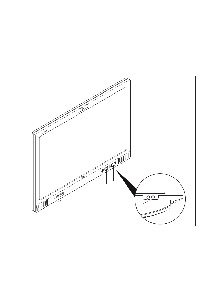
Front
1
2
9
7
6
5
4
8
3
2
1=Multi
2 = Loudspeaker
3=USB3
4 = Microphone port
5=Hea
Fujitsu 7
media module with camera
crophone (only ESPRIMO
and mi
24, optional)
K557/
.0 ports
dphone port
6=Hardd
7 = Power-on indicator
8=Scre
9 = On/off switch
isk indicator
en brightness buttons on the
rside
unde
Page 12
Ports and Operating Elements
Left side
MicrophoneportHeadphonesportExpressCardslotUSBport
As an option, a SmartC ard reader can be installed in the optical drive bay.
4
3
2
1
1 = Optical drive (DVD or Blue-ray, only
ESPRIMO K557/24 and K558/24)
3 = Insert/eject b utton, optical drive
4 = Optical drive status indicator (optional)
2 = Emergency removal
8 Fujitsu
Page 13

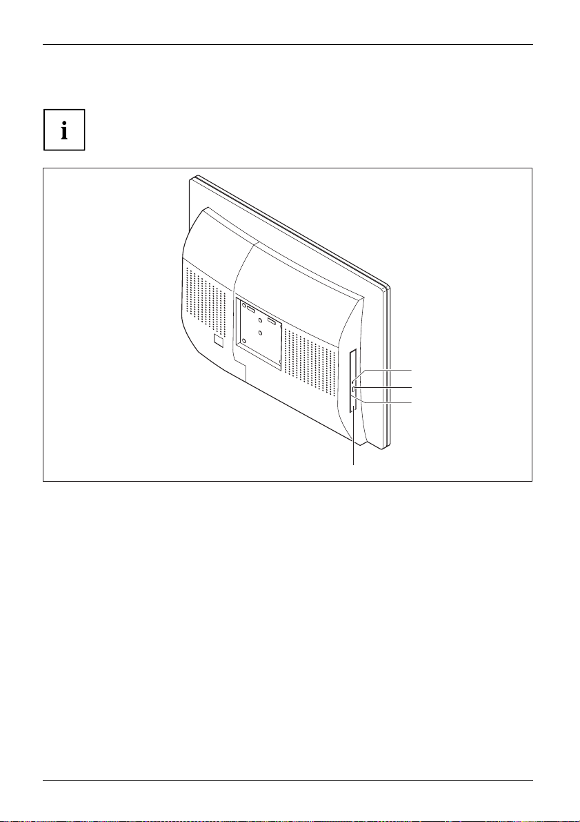
Rear
Ports and Operating Elem ents
1
2
4
5
6
3
1 = Service cover
2 = Cover for ports
3 = Cover for main switch
Fujitsu 9
4 = Security Lock device
5 = Padlock mounting option
6 = Clip
Page 14

Ports and Operating Elements
Rear side (under cover)
1 2
1 = PS/2 mouse por
2 = Serial port (optional)
3 = USB 2.0 ports
4 = DisplayPort port
5 = USB 3.0 port
6 = PS/2 keyboard port
t
s
3 46
7 = LAN port
8 = Audio output (Line Out)
9 = Audio input (
10 = Main switch
11 = Power conne
8 91011753
Line In)
ction (AC IN)
10 Fujitsu
Page 15

Important notes
ImportantnotesNotes
In this chapter you will find information regarding safety which it is essential to
take note of when working with your device.
Safety information
SafetyinformationNote
Please note the informat
and in the following safe
When installing and ope
environmental conditi
the instructions in C ha
When setting up the dev
thecasingreceives
cover the ventil ati
You must only opera
device is set to the
The main switch and
the mains voltage
you must pull the m
Only operate th
Caution, compo
The activitie
performed wit
Repairs to th
Incorrect re
to the equipm
e device with the casing closed.
nents in the system can get very hot.
s described in these instructions must always be
h the greatest care.
e device must only be performed by qualified technicians.
pairs could put the user at great risk or cause serious damage
ent (electric shock, risk of fire).
ion provided in the "Safety/regulations" manual
ty notes.
rating the device, please observe the notes on
ons in Chapter "
pter "
Getting start ed", Page 14.
ice, make sure there is clearance all around it so that
enough ventilation. I n order to avoid overheating, do not
on areas of the monitor or the device.
te th e device if the rated voltage used by the
local mains voltage.
the ON/OFF switch do not disconnect the device from
. For complete disconnection from the m a ins voltage,
ains plug out of the socket.
Technical data", Page 59 as well as
Important notes
Fujitsu 11
Page 16

Important notes
Safety notes for the system
This device complies with the relevant safety regulations for data processing equipment,
including electronic office machines for use in an office environment. If you have
any questions about whether the device can be used in the intended environment,
please contact your sales office or our Service Desk.
• The display surface of the device is se n sitive to pressure and scratches. You should therefore
be careful with the display surface in order to avoid lasting damage (scratches).
• If the device is brought into the installation site from a cold environment, condensation
can form. Before operating the device, wait until it is absolutely dry and has reached
approximately the same temperature as the installation site.
• When installing and operating the device, please observe the notes on ambient
conditions in "
an ergonomic video workstation", Page 15.
• To ensure sufficient ventilation, the air inlet and outlet openings of the device must be kept clear.
• The device automatica lly sets itself to the correct voltage within the range from 100 V to 240 V.
Make sure that the local mains voltage is neither higher nor lower than this range.
• Ensure that the power socket on the device and the mains outlet are freely accessible.
• The on/off switch does not disconnect the device from the mains voltage. To completely
disconnect from the mains voltage, you must remove the mains plug from the mains socket.
• The device is equipped with a power cable that complies with safety standards.
• Use the supplied power cable only.
• Lay the cables in such a way that they do not create a hazard (dange r of tripping)
and cannot be damaged. When connecting the device, observe the relevant notes
in chapter "
• No data transfer cables should be connected or disconnected during a thunderstorm.
• Make sure that no objects (e.g. jewellery chains, paper clips, etc.) or liquids get
inside the device (danger of electric shock, short circuit).
• The device is not waterproof! Never immerse the device in water and protect
it from spray water (rain, sea water).
• In an emergency (e.g. damaged casing, operation controls or cables, penetration
of liquids or foreign matter), switch off the device, disconnect the power plug
and contact your sales out let or our Service Desk.
• Only set the resolution and refresh rates that are indicated in chapter "
data", Page 59. If you set other values, you may damage the device. If you are
in any doubt, contact your sales outlet or our Service Desk.
• Use a screen saver with moving images and activa te the power management for
your monitor to prevent still images from "burning in".
• We recommend that you place your device on a durable, non-slip surface. In view
of the many different finishes and varnishes used on furniture, it is possible that the
feet of the device may mark the surface they stand on.
Technical data", Page 59 and the instructions in "Setting up
Connecting external devices" , Page 24.
Technical
12 Fujitsu
Page 17
Transporting the device
DeviceTrans portationRe-trans portation
Transport all devices separately in their original packaging or in a packaging
that protects them from knocks and jolts.
Unpack them only at the insta llation site.
If the device is brought from a cold environment into the room where it will be used,
condensation may occur. In order to avoid dama ge to the device, wait before preparing
it for use until the device has reached the ambient temp erature and it is absolutely dry.
Cleaning the device
e
Device,Transporta tionRetransportationSystemunit,see Devic
Turn off all power and equipment switches and disconnect the power
plug from the m ains outlet.
Do not clean any interior parts yourself, leave this job to a service technician.
Do not use any cleaning agents that contain abrasives or may corrode
plastic (alcohol, thinner or acetone).
Never clean the device with water! Water entering into the device could
present a serious risk to users (e.g. electric shock).
Ensure that no liquid enters the system.
Important notes
Thesurfacecanbe
moistened in mil
Use disinfecta
cleaned with a dry cloth. If particularly dirty, use a cloth that has been
d domestic detergent and then carefully wrung out.
nt wipes to clean the keyboard and the mouse.
Energy saving, disposal and recycling
DisposalEnergysavingRecycling
You ca n find information on these subjects on the Recovery DVD or on our website
http://www.fujitsu.com/fts/about/fts/environment-care/").
("
Fujitsu 13
Page 18

Getting started
Getting started
Gettingstarted
Unpacking and checking the delivery
It is recommended not to throw away the original packaging material! It may be
required for reshipment at some later date.
PackagingContentsofdeliveryPackaging,
► Unpack all the individual parts.
► Check the contents of the package for any visible damage caused during transport.
► Check whether the delivery conforms to the details in the delivery note.
► Should you discover that the delivery does not correspond to the delivery
Steps for initial setup
Preparingforfirstuse,overvie wPreparingforuse,
Only a few steps are necessary to put your new device into operation for the first tim e:
• Select a location for device and set up device
• Connecting external devices such as a m ouse and keyboard
• Check the voltage a t the mains outlet and connect the device to an electrical outlet
• Switch the device on
You will learn more about the individual steps in the following sections.
Please observe the safety information in th e "Important notes", Page 11 chapter.
The display surface of the device is sensitive to pressure and scratches.
Always hold the device by the casing!
note, notify your local sales out let immediately.
External devices
If you have received other external devices in addition to your own device (e.g.
a printer), do not connect these until after the initial installation. The following
sections describe how to connect these external devices.
Drives and boards
If you have received drives or boards with your device, please do no t install
them until after first-time setup. How to install drives and boards is described
System expansions", Page 48 chapter.
in the "
14 Fujitsu
Page 19

Settingupthedevice
WorkstationErgonomicDevice
When installing your device, please read the recommendations and saf ety
notes in the "Safety/regulations" manual.
We recomme nd that you place your device on a surf ace which is not slippery. In
view of the many different finishes and varnishes used on furniture, it is possible
that the rubber feet will mark the surface they sta n d on.
Depending on the location of your device, bothersome vibrations and noises may
occur. To prevent this, a distance of at least 10 mm / 0.39" should be maintained
from other devices on casing sides without ventilation surfaces.
In order to avoid overheating, do not cover the ventilation areas
of the monitor or the device.
A minimum distance of 200 mm / 7.87" from the device must be
observed for ventilation areas.
Do not expose the device to extreme ambient conditions (see "
section "Ambient conditions"). Protect the device against dust, humidity and heat.
When the lighting conditions are unfavourable (for instance direct sunlight), reflections
may occur which can cause the displayed characters to be difficult to read. Suitable
ambient lighting is necessary to avoid these kinds of reflections.
In addition, align your system according to the ambient lighting conditions, for instance
by changing the position of the display (horizontal or vertical angle).
Setting up an ergonomic video workstation
► Do not position the video workstation
opposite a window (1).
Getting started
Technical data", Page 59,
1
Fujitsu 15
Page 20

Getting started
► Position the system outside the reach
1
of a light source (1).
► Position the keyboard where it is
easiest to reach (1).
1
► Position the s
to the screen (
ystem so that the eye distance
1) is around 50 cm / 20 inches.
1
50 cm
16 Fujitsu
Page 21

Getting started
► Position the device for optimum viewing
(1). The monitor should not extend beyond
the acceptable viewing range (2).
Adjusting the inclinat
The monitor can be tilted up to +20° backwards from its vertical position.
► Hold the monitor with both hands on the left and right sides of the casing
and move it to the desired angle.
ion
Adjusting the rotation
The device can be rotated by ±170°.
► Grasp the device with both hands on the right and left edge of the casing
and turn it to the desired position.
Adjusting the height
► Switch the device off.
► Disconnect the mains plug.
► Disconnect all cables from the front of the device.
Fujitsu 17
Page 22

Getting started
Removing covers
1
► Press the tabs in the direction of the
arrow (1) and hold.
2
► Pull the cover off the foot in the
direction of the arrow (2).
► Press a blunt, thin o
through the drille
bject carefully
d holes in the direction
of the arrow (1).
The covers are pushed out (2).
1
1
1
1
1
2
2
2
2
1
18 Fujitsu
Page 23

2
2
The topmost cover must only be removed if the device is to be
positioned in the top position of the foot.
Adjusting the height
The display sur
Always hold the
Getting started
► To remove the topmost cove r, manually
push the cover out from behind (1).
1
1
1
1
face of the device is sensitive to pressure and scratches!
device by the casing!
► Lay the monitor on its front on a soft surface.
► Remove the screw (1) by hand.
1
Fujitsu 19
Page 24

Getting started
2
2
1
► Slide the foot in the direction of the arrow (1) until the extension screws are located
in the large diameter of the lengthways hole (2).
► Remove the foot.
► Choose one of the 4 height settings and mount the foot at the desired h eight.
► Lock the exten sion screws into place in the small diameter of the lengthways hole.
► Tighten the screw (1) by hand.
1
20 Fujitsu
Page 25

Mounting covers
Getting started
► Press the covers onto the foot in th e direction
of the arrow, until the covers engage.
► Push the cover onto t
direction of the ar
1
he foot in the
row (1).
Fujitsu 21
Page 26

Getting started
Information on how to fit a VESA mount
monitor base carrier
Operate the unit horizontally only. Operation in other positions is not permitted.
Your device can be mounted on a VESA mount monitor base c arrier:
• The device weights over 6 kg. Use a suitable VESA mount monitor base carrier
and suitable mounting m aterials (M4 screws).
• The screw holes for the
• The maximum screw insertion depth is 10 mm.
• When mounting on a VES
ventilation openin
• For additional information, see the manual supplied with y our VESA mount monitor base c arrier.
VESA mount monitor base carrier are spaced 100 mm apart.
A mount mounting hole, ensure that the
gs are not covered.
22 Fujitsu
Page 27

Getting started
Removing the c over for external devices ports
Preparingforoperation
2
1
► Press the clip in the direction of the arrow.
► Lift the cover for the external devices ports
(2) in the direction of the arrow (1).
Fujitsu 23
Page 28

Getting started
Connecting the power cable
PreparingforoperationPowercable
Observe the safety notes in the enclosed "Safety/Regulations" manual.
The supplied power cable conforms to the requirements of the country in
which you purchased your device. Make sure that the power cable is approved
for use in the country in which yo u intend to use it.
1
► Connect the power cable to the power connector (1) of the device.
► Plug the mains supply plug into an earthed mains supply socket (2).
2
Connecting external devices
Read the documen tation on the external device before connecting it.
With th e exception of USB devices, always remove all power plugs
before connecting external devices!
Do not connect or disconnect cables during a th understorm.
Always take hold of the actual plug. Never unplug a cable by pulling the cable itself.
To ensure that your device works properly, only use the connection cable
supplied or only use a high-quality connection cable.
24 Fujitsu
Page 29

Getting started
Ports on the device
PortsExternaldevicesDevice
The ports are located on the front and rear of the device. The ports available on
your device depend on the configuration level you have selected. The standard ports
are marked with the symbols shown below (or similar).
DP DisplayPort
DisplayPort
Audio output (Line Out)
AudiooutputLineout
USB 3.0 - Universal Serial Bus, blue
(device-dependent)
LAN port
LANport
Audio input (Line in)
Audioinput
Serial port
Serialport
PS/2 mouse port, g reen
PS/2mouseport
PS/2 keyboard port, purple
PS/2keyboardport
USB 2.0 - Universal Serial
Bus, black
UniversalSerialBus
Some of the connected devices require special software (e.g. drivers) (refer to the
documentation for the connected device and operating system).
Connecting the mouse
You can connect a USB mouse or a PS/2 mouse to your device.
Mouse,Connecting,
Connecting a USB mouse
► Connect the USB mouse to one of the USB ports on the device.
USBport,USBport
Connecting a PS/2 mouse
The PS/2 mouse is only detected by the device if you connect the mouse when
the device is switched off and then switch the device on again.
► Connect the PS/2 mouse to the PS/2 mouse port of the device.
PS/2mouse,Connecting,PS/2mouse,
► Switch yo
ur device on again.
Fujitsu 25
Page 30

Getting started
Connecting the keyboard
You can connect a USB keyboard or a PS/2 keyboard to your device.
Keyboard,Connecting,
Connecting a USB keyboard
Use the supplied keyboard cable only.
USBport,Connecting,
► Plug the flat rectangular USB connector of the keyboard cable into a USB port of the device.
USBport
Connecting a PS/2 keyboard
Use the supplied keyboard cable only.
ard
ConnectingaPS/2keybo
Connecting,
► Switch your device off.
► Plug the round plug of the keyboard cable into a keyboard port of the device.
► Switch your device on again.
Connecting external devices to the serial interface
SerialinterfaceSerialinterface,Externaldevices,Devices,
The PS/2 keyboard is only detected by the device if you connect the keyboard
when the device is switched off and then switch the device on again.
Keyboard,
For an exact description of how to connect external devices to the corresponding
port, please see the external device documentation.
External devices (e.g. a printer or scanner ) can be connected to the serial port.
► Connect the data cable to the external device.
► Connect the data cable to the corresponding serial interface.
Port settings
Serialinterface,
You can change the settings of the port in th e BIOS Setup.
Device dr
Devicedrivers,
ivers
The devices connected to the serial interface req uire drivers. Your operating system
already includes many drivers. If the required drive is missing, install it. The latest
drivers are usually available on the Internet or will be supplied on a data carrier.
26 Fujitsu
Page 31

Connecting external devices to the USB ports
USBdevicesUSBportExternaldevicesDevices
You can connect a wide range of external devices to the USB ports (e.g.
printer, scanner, modem or keyboard).
USB devices and hot plug-enabled. This means you can connect and disconnect
USB cables while your device is switched on.
Additional information can be found in the documentation for the USB devices.
► Connect the data cable to the external device.
► Connect the data cable to one of the USB ports on your device.
Device drivers
External USB devices which you connect to one of the USB ports don’t usually
need their own drivers because the software required is already included in
the Operating System. If the device requires separate software, please follow
the instructions in the manufacturer’s documentation.
Getting started
Connect a second mo
DisplayPort
You can connect a second monitor via the DisplayPort.
nitor to the display port
► Connect the data cable to your
► Connect the dat
ALL-IN-ONE PC
port of the seco
acabletothedisplay
nd monitor.
Fujitsu 27
Page 32

Getting started
Mounting the cover for external devices ports
Preparingforoperation
2
1
► Place the cover on its mounting location.
► Slide the co ver in the direction of the
arrow (1) until the clip engages.
Ensure that all cables are guided through
the recess (2) in the cover and that
no cables are trapped.
► Guide all cables through the opening in
the base towards the rear.
28 Fujitsu
Page 33

Getting started
Switchingonforthefirst time: installing the software
Installing,Software,Installing,
Once the installation ha s been started the device must not be switched
off, unless the installation has been completed.
During installation, the device may only be rebooted when you are requested to do so!
The installation will otherwise not be carried out correctly and th e contents
of the hard disk must be completely restored.
If the device is integrat
the network protocol ar
Contact your network ad
When you switch on the d
is installed and config
as this process must n
Switch the device on
In order to avoid overheating, do not cover the ventilation areas of the device.
► Switch the devi
ce off at the main switch.
Themainswitc
In delivery st
h is located on the rear of the device under a cover (see "
atus, the main switch is at position "I".
ed into a network, the user and server details as well as
e required during the software installation.
ministrator if you have any questions about these settings.
evice for the fi rst time, the supplied software
ured. Plan a reasonable amount of time for this,
ot be interrupted.
Rear", Page 9).
1
► Press the ON/OFF switch on the front of the device.
The power indicator glows and the device starts.
Fujitsu 29
Page 34

Getting started
Installing the software
► During installation, follow the on-screen instructions.
Software,Installing,
► If anything is unclear regarding the data you are a sked to input, read the
online Help in your operating system.
For more information on the system as well as drivers, utilities and updates
http://www.fujitsu.com/fts/support" on the Internet.
see "
You c a n find information and help on the Windows operating system functions
on the Internet at "
http://windows.microsoft.com".
30 Fujitsu
Page 35

Operation
Switch the device on
In order to avoid overheating, do not cover the ventilation areas of the device.
► If necessary, switch the device off at the ma in switch.
The main switch is located on the rear of the device unde r a cover (see "Rear", Page 9).
► Press the ON/OFF switch on the front of the device.
The power indicator glows and the device starts.
Operation
Switching the de
► Shut down the operating system in the proper way. With Windows: in
the Start menu via the Exit function.
DeviceMonitor
► If the operating system does not automatically switch the device into energy-saving mode or
switch it off, press the ON/OFF switch. Warning, this could lead to a loss of data!
If the de vice is ready-to-use, the device consumes a minimum of energy.
► Switch the device off at the main switch.
The device no longer uses any power.
The main switch and the ON/OFF switch do no t disconnect the
device from the mains voltage.
► For complete disconnection from the mains voltage, pull the mains plug out of the socket.
vice off
Fujitsu 31
Page 36

Operation
LCD screen
LCDscreenNotes
High-quality TFT monitors are installed in systems from Fujitsu Technology Solutions GmbH. For
technical reasons, TFT monitors are manufactured for a specific resolution. An op timal, clear
picture can only be ensured with the correct resolution intended for the relevant TFT monitor. A
screen resolution which differs from the specification can result in an unclear picture.
The screen resolution of the LCD monitor of your system is optimally set at the factory.
TFT monitors are operated with LED background lighting. The luminosity of
the background lighting can decrease during the period of use of the system.
However, you can set the brightness of your monitor individually.
Adjusting the brightness
BrightnessBackgroundlightingLCDscreen
1
2
1 = Decrease screen brightness 2 = Increase screen brightness
► Press the screen brightness buttons on the un dersi de (1, 2) to adjust the brightness of the screen.
The adjustment changes the background illumination.
32 Fujitsu
Page 37

Indicators on the device
The indicators are on the front of the casing.
1
3
2
No. indicator Description
eLED
1 Multimedia modul
indicator (opti
2 Hard disk indic
3 Power-on indi
4
Drive indicator (optional,
only ESPRIMO K557/24
and K558/24)
onal)
ator
cator
TheLEDlightsupb
The indicator l
is being acces
• The indicator
The device is switched on.
• The indicato
The device is in energy-saving mode. After being switched on
with the ON/OFF switch, the device powers up or returns to the
state it was in before it entered energy-saving mode.
• The indica
The device is switched off (disconnected from the mains) or is
ready to operate. If the device is ready to operate, it can be
switched on with the ON/OFF switch.
The indicator lights up when the optical drive of the device is being
accessed. You must never under any circumstances remove the
CD/DVD while the indicator light is on.
Operation
4
lue when the camera is active.
ights up when the hard disk drive in the device
sed.
is illuminated:
risflashing:
tor is not illuminated:
In an energy-saving mode the device must not be switched off with the main switch
or disconn ecte d from the mains supply, as this may result in data loss.
Fujitsu 33
Page 38

Operation
Keyboard
KeyboardKeyboard,Keyboard,Keyboard,Keyboar d,Keyboard,AlphanumerickeypadCursorkeysKeys,FunctionkeysNumerickeypadNumerickeypad
The illustrated keyboard is an example and may differ from the model you use.
1 2
345
1 = Function keys
2 = On/off switch (optional)
4=Cursorkeys
5 = Numeric keypad (calculator keypad)
3 = Alphanumeric keypad
Important k
Keyskeyboardshortcuts
eys and keyboard shortcuts
The description of the following keys and keyboard shortcuts applies to Microsoft
operating systems. Details of other keys and keyboard shortcuts can be found in
the documentation for the relevant application program.
Key / key combination Description
On/off switch (optional)
itch
ON/OFFsw
Button,
Depending on the setting in the BIOS Setup, the device can be switched
on or off with this switch. Some operating systems allow you to configure
additional functions of the ON/OFF switch in the Control Panel.
WithsomekeyboardstheON/OFFswitchcanonlybeusedwithanACPI
(Advanced Configuration and Power Management Interface). Otherwise
the key is inoperative. The mainboard must support this function.
Enter key
Keys,Keys,Keys,
confirms the highlighted selection. The Enter key is also referred to as
the "Return" key.
34 Fujitsu
Page 39

Key / key combination Description
Windows button
Buttons
The Windows button switches between the start screen and the last
used application.
Menu key
Keys,
The menu button opens the menu for the active application.
Shift key
Keys,Keys,
enables upper-case letters and the upper key symbols to be displayed.
Alt Gr button (device-dependent)
Keys,
produces a character shown on the bottom right of a key (e.g. the @
sign on the
Num Lock key
Keys,
By pressing the Num Lock key you switch between the upper- and
lower-case levels of the calculator keypad.
When the Num Lo ck indicator is lit the numeric keypad and arithmetic
keys are active.
When the Num Lock indicator is not lit the cursor control functions on the
Numeric keypad are active.
Ctrl key
Ctrl
AltCtrl
++
Keys,KeysKeysKeys,
performs a special operation when pressed in conjunction with another
key. The
Windows secur
Ctrl+Alt+DelCtrl+Alt+DelKeysKeyboa rdsho
Del
This key comb
Ctrl
rtcuts
Operation
Q
key).
key is also called the "Control" or "Control key".
ity/Task-Manager
ination op ens the Windows Security/Task Manager window.
Fujitsu 35
Page 40

Operation
Multimedia module (optional)
Multimediamodule
The multimedia module has the following functions:
• Multimedia: for video recordings up to a resolution of 1920 x 1080 pixels (1080 p)
• Digital microphone: for stereo audio recordings
Depending on the software used, you can use the multimedia module to take
pictures, record video clips or take part in web chats.
The multimedia module has a separate LED indicator. The LED lights up
blue when the camera is active.
• The picture quality depends on the lighting conditions and the software being used.
• You can only operate the multimedia module with a particular application (e.g. an Internet
• When using the multimedia module, the system support (e.g. the table) should not
• The multimedia module automatically adjusts itself to the current light level. For this
As an option, your system is equipped with a multimedia module,
which is integrated in the device.
You c an activate or deactivate the camera with the installed software or in the BIOS Setup.
The digital microphone can only be activated or deactivated in the BIOS-Setup.
telephony prog ram or a video conferencing program which supports multimedia).
wobble or vibrate, as this affects the picture quality.
reason the LCD display may flicker while the light level is adjusted.
Further information on use of the multimedia module and additional
settings for your multimedia module can be found in the help function of
the program using the multimedia module.
Wireless LAN/Bluetooth radio components (optional)
The insta
the certi
Switching the wireless components on and off
With th
compo
Pay at
provi
Deta
incl
36 Fujitsu
llation of radio components not approved by Fujitsu will invalidate
fications issued for this device.
e programme Device Manager you can switch off the wireless
nents on or off separately.
tention to the additional safety notes for devices with wireless components
ded in the "Safety/Regulations" manual.
ils on using Wireless LAN can be found in the online help system
uded with the W ireless LAN softwa re.
Page 41

Settings in BIOS Setup Utility
BIOSSetupUtilitySystemsettings,BIOSSetupUtilityConfiguration,BIOSSetupUtilitySetupSystemconfigurationHardwareconfiguration
The BIOS Setup Utility allows you to set the system functions and the
hardware configuration for your device.
When it is supplied, the device is set to factory default settings. You can change
these settings in the BIOS Setup Utility menu. Any changes you make take effect
as soon as you save and exit the BIOS Setup Utility.
The BIOS Setup Utility program contains the following menus:
Menu Description
Main
Advanced
Security
Power
Event Logs
Boot
Save & Exit
System settings such as
Advanced system setti
Password settings and security functions
Energy saving function
Protocol settings
Configuration of t
Exits the BIOS Se
The fo llowing function keys can also be used:
Key Description
Esc
To e xi t th e BIOS Setup Utility.
The current settings are not saved.
F2
To reject changes and load the previous configuration of the BIOS Setup
Utility.
F3
F4
To load the
To e xi t th e
The curre
default configuration of the BIOS Setup Utility.
BIOS Setup Utility.
nt settings are saved.
time and date
ngs
he start-up sequence
tup Utility
Operation
Starti
► Start the device (switch off/on or reboot the Operating System).
ng the BIOS Setup Utility
BIOSSetupUtility
ing on the setting for Fast Boot in the BIOS Setup Utility the following display,
Depend
licable, appears on the screen on start-up:
if app
<F2> BIOS Setup <F12> Boot Menu
► Press the function key
► If a p
assword has been assigned, enter the password and press the Enter key.
ou have forgotten the password, contact your s ystem administrator
If y
ontact our customer service centre.
or c
F2
.
The BIOS Setup Utility starts.
Fujitsu 37
Page 42

Operation
Operating BIOS Setup Utility
BIOSSetupUtility
Press theF1key to display help on the operation of the BIOS Setup Utility. T he description
of the i ndividual settings is s hown in the right-hand window of the BIOS Setup Utility.
With the
► Use the cursor keys
The menu is displayed on the screen.
► Select the option you want to change with the cursor keys
F3
key you can load the default settings of the BIOS Setup Utility.
←
→
or
to select the menu you wish to access to make changes.
↑
or↓.
► Press the Enter key.
► Press the
ESC
key to exit the selected menu.
► For future reference, make a note of the changes you have made (for example, in this manual).
Exiting B IOS Setup Utility
BIOSSetupUtility
You need to select the desired option in the Save & Exit menu and activate it by pressing the Enter key:
Save Changes and Exit - Save the changes and exit the BIOS Setup Utility
► To save the current menu settings and exit the BIOS Setup Utility, select
Save Changes and Exit and Yes .
The device is rebooted and the new se ttings come into effect.
Discard Changes and Exit - Discard changes and exit the BIOS Setup Utility
► Select Discard Changes and Exit and Ye s to discard the changes you have made.
The settings which applied when BIOS Setup Utility was called up remain effective.
The BIOS Setup Utility is terminated and the device is rebooted.
Property and data protection
protection
ection
measures
Property
Dataprot
Security
Software functions and mechanical locking offer a broad range of functions for protecting your device
and your personal data against theft and unauthorised access. You can also combine these functions.
38 Fujitsu
Page 43

Anti-theft protection and lead-sealing
Anti-theft protection
You can protect your device against theft with a padlock and a chain, which you have
previously connected to a fixed object, or with a Kensington Lock Microsaver (steel cable,
accessories). Consult the manual for your Kensington Lock Microsaver.
► Guide a padlock through the hole (1).
1
► Secure the Kensington Lock Microsave r
in the Security Lock device (1).
Operation
1
Fujitsu 39
Page 44

Operation
Lead-sealing
To prevent unauthorised persons from opening the casing, the casing can be lead-sealed.
► To do this, feed a lead-seal through the
hole (1) and seal the chain with the lead seal.
1
BIOS setup security functions
ons
Securityfuncti
BIOSSetup
The Security menu in BIOS Setup offers you various options for protecting your
personal data against unauthorized access, e.g.:
• Prevent unauthorized access to BIOS Setup
• Prevent unauthorised system access
• Prevent unauthorised access to the settings of boards with their own BIOS
• Activate virus warnings
• Protect BIOS from overwriting
• Protect the device from being switched on by an external device
You can also combine these functions.
A detailed description of the menu Security and how to assign passwords can
be found in the BIOS manual for your device.
40 Fujitsu
Page 45

Operation
SmartCard reader (optional)
Securityfunctions,
The SmartCard reader can be installed in the optical drive bay as an
option. In this case, there is no optical drive.
SmartCards are not supplied as standard equipment. You can use all SmartCards that comply with
the ISO standard 7816-1, -2 or -3. These S martCards are available from various manufacturers.
With the appropriate software y ou can use your SmartCard as an alternative to password protection,
but also as a digital signature, for encrypting your e-mails or for home banking.
We recom mend that you always use two SmartCards. Always keep one of the SmartCards
in a safe place if you are carrying the other SmartCard w ith you.
In order to be able to take advantage of all the security features of your system, you will need a
CardOS SmartCard and the Workplace Protect software from Fujitsu Technology Solutions.
The SmartCard can only be used with a PIN, offering maximum protection even if
you lose the SmartCard. In order to maximise your security, the CardOS SmartCard
is disabled if three incorrect attempts are made to enter the PIN.
When you use the CardOS SmartCard fo r the first time, you will either need to enter the
preset PIN "12345678" or the PIN given to you by your systems administrator.
Inserting the SmartCard
Do not use force when inserting and removing the SmartCard.
Make sure that foreign objects do not fall into the SmartCard reader.
► Hold the SmartCard so that the chip
faces the front of the device.
► Push the SmartCard into the
SmartCard reader.
Fujitsu 41
Page 46

Explanatory information about stan
dard ISO 9241-307
Explanatory information abou
t
standard ISO 9241-307
Permanently unlit or lit pixels
Today’s production techniques cannot guarantee an absolutely fault-fre e screen display. Depending
on the total number of pixels (resolution), there may be a few constantly lit or unlit pixe ls or subpixels.
RGB RGB RGB
RGB RGB RGB
1 2
1 = Pixel 2 = Subpixel
Pixel
Subpixel
Pixel fault All 3 subpixels are lit/unlit. The result is a brighter or da rker pixel.
Subpixel fault Only one subpixel is lit/unlit. The resu lt is a pixel with missing colours.
A pixel consists of 3 subpixels, normally red, green and blue. A pixel is
the smallest element that can be generated by complete functionality of
the display.
A subpixel is a separately addressable internal structure within a pixel that
enhances th e pixel function.
The maximum permitted number of faulty pixels is stipulated in the international standard
ISO 9241 -307. The LCD displays from Fujitsu comply to at least Class I. Fujitsu guarantees
displays that are free of pixel faults, so that only subpixel faults may occur.
Examples:
A flat-screen display with a resolution of 192 0 x 1080 has 1920 x 1080 = 2073600 pixels. Each
pixel consists of three subpixels (red, green and blue), making a total of about 6,2 million subpixels.
According to ISO 9241-3 (Class I), a maximum of 2 lit and 2 unlit pixels plus 5 lit or 10 unlit subpixels,
or a corresponding combination, may be faulty (1 lit s ubpixel c ounts as two unlit subpixels). Because
Fujitsu supplies displays that are free of pixel faults, only subpixel faults enter into the evaluation.
42 Fujitsu
Page 47

Troubleshooting and tips
Refer to the safety notes in the "Safety/regulations" manual and in the "Gettin g
started", Page 14 chapter when connecting or disconnecting cables.
Troubleshooting and tips
If a fault occurs, try to c
• in this chapter
• in the documentation for the connected devices
• in the help systems of th
• in the documentation for your operating system
orrect it as described in the following documenta tion:
e software used
Help if problems occur
Should you encount
► Note the ID number
type rating plate
► Contact the Service Desk responsible for your country for clarification of the problem:
"
http://support.ts.fujitsu.com/contact/ser vicedesk". When you do this, please have
ready the ID number and serial number of your system.
er a problem with your computer that you cannot resolve yourself:
of your device. T he Ident-No. can be found on the
on the back of the device.
Troubleshooting
Power indicator remains off after you have switched on your device
Cause
The mains voltage supply is faulty. ► Check that the power cable is correctly
Internal power supply overloaded.
Remedy
plugged into the device and into a grounded
mains outlet.
► Check that the main switch at the rear of the
device is set to the "I" p osition.
► Switch the device on.
► Pull the power plug of the device out of the
mains outlet.
► Wait fo
► Plug the power plug into a properly grounded
► Swit
r about 3 minutes.
mains outlet again.
ch the device on.
Fujitsu 43
Page 48

Troubleshooting and tips
The device cannot be switched off with the On/Off switch.
Cause
System crash ► Press the On/Off switch for at least
Troubleshooting
4 seconds, until the device switches off.
Attention: Warning, this could lead to a loss o f
data!
The Operating System is not shut-down properly
in the process. Error messages a re therefore
possible the next time the system is booted.
The internal screen stays blank
Cause
Power saving has been activated (screen is
blank)
Brightness control is set to dark
The screen display becomes darker
Remedy
► Press any key on the keyboard.
or
► Deactivate the screen saver. If
necessary, enter the appropriate
password.
or
► Alter the brightness and/or contrast until
yougetapicture(see"
brightness", Page 32).
► Adjust the brightness contro l to bright (see
Adjusting the brightness", Page 32).
"
The background lighting has a limited lifetime.
► If your screen display becomes too dark,
contact our Service Desk.
► Check the ambient temp erature.
Adjusting the
44 Fujitsu
Page 49

Troubleshooting and tips
The external monitor remains blank
Monitor
Cause Troubleshooting
Monitor is switched off. ► Switch the external mon itor on.
Power saving has been activated (monitor is
► Press any key to continue.
blank).
Brightness is set to dark.
Screen output is set to the system’s LCD
monitor.
► Adjust the brightness of the monitor.
► Press the key combination to switch the
screen output, see "
Important keys and
keyboard shortcuts", Page 34.
The external monitor’s power cable or data
cable is not connected properly.
► Switch off the external monitor and the
system.
► Check whether the power cable is plugged
properly into the external monitor and into
the powe r socket.
► Check whether the data cable is properly
connected to the system and the external
monitor (if it is plugged in with a connector).
► Switch on the external monitor and the
system.
The external m onitor is blank or the image is unstable
ScreenMonitor
Cause Troubleshooting
The wrong external monitor has been selected
or the wrong screen resolution ha s been set for
the application program.
► Terminate the application program in
Windows by pressing
Alt+F4
error persists after terminating the program,
use the key combination for switching the
screen output (see "
Important keys and
keyboard shortcuts", Page 34), in order to
switch to the LCD monitor of the system.
Change the following setting:
► Set the scre en resolution: Set the screen
resolution as described in the documentation
for your operating system.
.Ifthe
Fujitsu 45
Page 50

Troubleshooting and tips
No mouse pointer displayed on the monitor
Cause
The mouse is not properly connected.
Troubleshooting
► Shut down the Operating System correctly.
► Switch the device off.
► Check that the mouse cable is properly
connected. If you are using an adapter or
extension lead for the mouse cable, check
the plug-in connection.
► Make sure that only one mouse is
connected.
► Switch the device on.
Date and time are not correct
Cause
Date and time are set incorrectly.
Troubleshooting
► Set the correct time and date under the
Operating System you are using.
or
► In the BIOS Setup, set the date or time.
SmartCard reader is not recognised
Cause
Chip card inserted incorrectly. ► Check whether you have inserted your
Troubleshooting
SmartCard into the SmartCard reader the
right way with the chip facing upwards.
► Check whether the SmartCard you are using
is supported. Your SmartCard must comply
with the ISO sta ndard 7816-1, -2, -3 and -4.
Error messages on the screen
Error messages and their explanations are provided:
• in the documentation for the programs used
Install
When installing programs or drivers, important files may be overwritten and modified. To
be able to access the original data in the event of any problems following installation,
you should backup your hard disk prior to installation.
46 Fujitsu
ing new software
Page 51

Troubleshooting and tips
Tips
Top i c Tip
Outofsystemresources ► Close unnecessary applicatio
or
► Run the applications in a different order.
Other important links:
• Warranty: "
• Service Desk: "www.fujitsu.com/fts/contact/servicedesk"
• Drivers & downloads: "ww
• Recycling: "www.fujitsu.com/fts/recycling"
www.fujitsu.
com/fts/support/warranty"
w.fujitsu.com/fts/download"
ns.
Fujitsu 47
Page 52

System expansions
System expansions
Upgrades,Device,SystemexpansionComponentsServicing
After consulting the Hotline/Help Desk, you may remove and install the components
described in this manual yourself.
The following illustrations may differ slightly from your device, depending on its configuration level.
If further docu mentation was delivered with your device, please also read this through carefully.
In addition, before removing or installing system components, please pay attention to the following:
Repairs to the device must only be performed by qualified technicians. Incorrect repairs
may greatly endanger the user (electric shock, fire risk) and will invalidate your warranty.
As the device has to be shut down in order to install/deinstall system hardware
components, it is a good idea to print out the relevant sections of this chapter beforehand.
The device must be switched off when installing/rem oving the system
expansions and may not be in energy-saving m ode.
Remove the power plug before opening the device.
Be careful that no wires become trapped when removing or installing components.
When installing components that become very hot, make sure that the maximum
permissible tem peratu re of the component s in operation is not exceeded.
It may be necessary to update the BIOS when carrying out a system expansion or
hardware upgrade. Please refer to the Help facility of the BIOS for more information.
48 Fujitsu
Page 53

System expansions
Information about boards
Take care with the locking mechanisms (catches and centring pins) when you
are replacing boards or components on boards.
Note that some components on the mainboard may be very hot if the device was
in use shortly before the casing was removed.
To prevent damage to the board or the components and conductors on it, please take care when
you insert or remove boards. Make sure expansion boards are inserted straightly.
Never use sharp objects (screwdrivers) for leverage.
Boards with electrostat
shown.
When handling boards fit
following points:
• You must always disc
object) before work
• The equipment and tools you use must be free of static charg es.
• Only touch or hold t
marked green (Touc
• Never touch pins or conductors on boards fitted with ESDs.
ic sensitive devices (ESD) are identifiable by th e label
ted with ESDs, you must always observe the
harge static build up (e.g. by touching a grounded
ing.
he boards by the edge or, if present, at the areas
h Points).
Preparing to remove components
Please observe the safety notes in the Chapter "Important notes", Page 11.
Pull th e mains plug out of the socket provided with contact protection.
► Switch the device off.
The device should not be in energy-saving mode.
► Remove all the cables from the device.
► Place the device on a stable, flat and clean surface. If necessary, place a slip-resistant
cloth on this surface to prevent the device from being scra tched.
Removing the service cover
► Prepare for remo val (see "Infor mation about boards", Page 49).
► Remove the cover for the ports (see "
Fujitsu 49
Removing the cover for external devices ports", Page 23).
Page 54

System expansions
► Remove the locking pin.
► Pull the tab (1) until the clip disengages.
► Slide the service cover in the direction
of the arrow (2).
► Lift the service cover off the device (3).
3
2
50 Fujitsu
1
Page 55

Mounting the service cover
1
2
System expansions
► Place the service c over in the correct
mounting position (1).
► Slide the service cover in the direction of
the arrow (2) until the c lip engages.
► Position the locking pin.
► Mount the cover for the ports (see "
► Complete the installation (see "
Fujitsu 51
Mounting the cover for external devices ports", Page 28).
Finishing component removal", Page 58).
Page 56

System expansions
Remove and install memory expan
MemorymoduleMainmemoryRemovingmemorySystemexpansionSystemexpansion
You must open the service cover to remove or install the memory module.
Please observe the safety information in chapter "Important notes", Page 11.
When installing/removing memory modules, the device must not be connecte d
to the current, see "
Only use memory extensions that have been approved for your device,
see chapter "
Never use force when installing or removing a memory extension.
Make sure that foreign objects do not fall into the memory extension compartment.
Preparing to remove comp onents", Page 49.
Technical data", Page 59.
sion
Removing a cover
► Remove the service cover "Removin g the serv ice cover", Page 49
1
3
2 2
► Loosen the screw (1).
► Unhook the
52 Fujitsu
cover (2) with a slight twisting movement (3) and remove it.
Page 57

Installing a memory module
1
2
System expansions
► Insert the memory module (1) in its
slot as follows (2).
► Insert the memory mo
the contacts and th
in the direction of
2
1
MemoryexpansionMemorymodule
► Carefully push the memory module
dule in the slot with
e recess (a) facing
the arrow (1).
downwards until you feel it click
into place (2).
a
Fujitsu 53
Page 58

System expansions
Removing memory modules
3
2
1
1
► Carefully push the two mounting
clips outwards (1).
MemoryexpansionMemorymodule
The memory module snaps upwards (2).
► Pull the memory module
slot in the direction
(1) out of its
of the arrow.
1
54 Fujitsu
Page 59

System expansions
Attaching the cover
3
2
1 1
► Place the cover (1) in its installation opening with a slight twisting movement (2).
The cover must hook into place.
Take care not to trap any cables when fitting the cover.
► Fasten the cover in place with the screw (3).
► Re-fasten th
e service cover (see "
Mounting the service cover", Pag e 51)
Installing a nd removing the hard disk drive
The following information applies to FUJITSU ESPRIMO K557/K558 only
Installing a hard disk drive
► Remove
Fujitsu 55
the service cover (see "
Removing the service cover", Page 49 ).
Page 60

System expansions
► Secure the EasyChange rails to the side of the hard disk drive by inserting the upper
pins of the EasyChange rail in the corresponding holes of the hard disk.
► Slide the hard disk drive with the
EasyChange rails into the drive cage in
the direction of the arrow (1). Ensure
that the hard disk drive screws face the
rear wall of the housing.
1
56 Fujitsu
Page 61

System expansions
► Connect the cables to the hard disk drive.
► Re-fasten the service cover (see "
the service cover", Page 51).
1
Mounting
It may be necessary t
Removing the har
► Remove the service cover (see "Removing the service cover", Page 49).
1
o mo d ify the entry for the drive in the BIOS Setup.
ddiskdrive
► Disconnect the
to the hard disk
cables (1) connected
drive.
Fujitsu 57
Page 62

System expansions
► Slightly press together t he EasyChange
rails mounted on the hard disk drive (1) and
pull the hard disk drive completely out of the
drive cage in the direction of the arrow (2).
1
2
► Pull the EasyChange rails off the hard disk drive.
► If you no longer need the EasyChange rails, secure them again at their location in the drive cage.
It ma y be necessary to modify the entry for the drive in the BIOS Setup.
1
Finishing component removal
► Recon
58 Fujitsu
nect the previously disconnected cables to the device.
Page 63

Technical data
Technical data
ESPRIMO K557/24 and
K558/24
Electrical data
Safety regulations complied
with
Protection class II
Rated voltage range 100 – 240 V
Rated frequency 50 – 60 Hz (AC)
Max. rated current 1.7 – 0.7 A
Dimensions
With x Depth x Height (without
foot)
Width x Depth x Height (with
foot, monitor in the second
position from bottom)
Min./max. Height (with foot) 411/516 mm / 16.18/20.31 inch 389/494 mm / 15.31/19.45 inch
Weight
In basic configuration approx. 6.3 kg / 13.9 lbs approx. 5 kg / 11 lbs
With foot approx. 9.5 kg / 20.9 lbs approx. 8.1 kg / 17.9 lbs
Ambient conditions
Environment class 3K2
Environment class 2K2
Temp erature
Operation (3K2) 15 °C .... 35 °C / 59 °F ... 95 °F
Transportation (2K2) –25 °C .... 60 °C / –13 °F ... 140 °F
The formation of condensation is not permitted while the device is in operation !
Clearance required to ensure adequate ventilation:
without air vents
with air vents
Maximum resolution 1920 x 1080 1440 x 900
Pixel error class according to
ISO 9241-307
Multimedia module
Camera resolution 1920 x 1080 (1080 p)
Microphone Digital, stereo
IEC 60950-1, EN 60950-1, UL 60950-1
CSA 22.2 No.60950-1
560 mm x 93 mm x 368 mm /
22.05 inch x 3.66 inch x
14.50 inch
560 mm x 258 mm x 446 mm /
22.05 inch x 10.16 inch x
17.56 inch
DIN EN 60721-3-3
DIN EN 60721-3-2
min. 10 mm / 0.39"
min. 200 mm / 7.87"
Class I
ESPRIMO K557/20 and
K558/20
460 mm x 93 mm x 331 mm /
18.11 inch x 3.66 inch x
13.03 inch
459 mm x 258 mm x 424 mm /
18.07 inch x 10.16 inch x
16.70 inch
–
–
Fujitsu 59
Page 64

Technical data
The data sheets of these devices contain further technical data. You can find
the data sheets on the Internet at "
http://www.fujitsu.com/fts".
60 Fujitsu
Page 65

Index
Index
A
Alphanumeric keypad 34
Audio input 25
Audio output 25
B
Background lighting 32
BIOS Setup
security functions 40
BIOS Setup Utility
calling 37
exiting 38
operating 38
settings 37
Brightness 32
Button,
ON/OFF switch 34
Buttons
Windows button 35
C
Components
installing/removing 48
Configuration, BIOS Setup Utility 37
Connecting a PS/2 keyboard 26
Connecting,
keyboard 26
mouse 25
PS/2 keyboard 26
PS/2 mouse 25
USB keyboard 26
Contents of delivery 14
Ctrl+Alt+Del 35
Cursor keys 34
D
Data protection 38
Device
Ports 25
setting up 15
switching off 31
transporting 13
Device drivers,
serial interface 26
Device,
transporting 13
upgrades 48
Devices
connecting 27
Devices,
connecting 26
DisplayPort 25, 27
Disposal 13
E
Energy saving 13
Ergonomic
Workstation 15
ExpressCard slot 8
External devices
connecting 27
Ports 25
External devices,
connecting 26
F
Function keys 34
G
Getting started 14
H
Hardware configuration 37
Headphones port 8
I
Important notes 11
Installing,
software 29–30
switching on for the first time 29
K
Keyboard 34
keyboard shortcuts 34
Keyboard shortcu ts 35
Keyboard,
alphanumeric keypad 34
connecting 26
cursor keys 34
function keys 34
numeric keypad 34
port 26
Keys 34
Ctrl 35
Ctrl+Alt+Del 35
Fujitsu 61
Page 66

Index
Keys,
Alt Gr 35
Control 35
Ctrl key 35
cursor keys 34
Enter 34
Enter key 34
menu key 35
Num Lock 35
Return 34
shift 35
shift key 35
L
LAN port 25
LCD screen
Background lighting 32
notes 32
Line out 25
M
Main memory
see Adding memory 52
Memory expansion
installing 53
removing 54
Memory module
important notes 52
installing 53
removing 54
Microphone port 8
Monitor
drifting display 45
remains blank 45
switching off 31
Mouse,
connecting 25
Multimedia module 36
N
Note
safety 11
Notes
important 11
LCD screen 32
Numeric keypad 34
O
ON/OFF switch 34
Overview
Device 5
P
Packaging 14
Packaging,
unpacking 14
Ports 7, 25
Power cable
connection 24
Preparing for first use, overview 14
Preparing for operation 23–24, 28
Preparing for use,
overview 14
Property protection 38
PS/2 keyboard port 25
PS/2 mouse port 25
PS/2 mouse,
connecting 25
port 25
R
Re-transportation 13
Recycling 13
Removing memory
see Adding memory 52
Retransportation 13
S
Safety information 11
Screen
no screen display 45
Security functions
BIOS Setup 40
Security functions,
SmartCard 41
Security measures 38
Serial interface 26
Serial interface,
connecting devices 26
settings 26
Serial port 25
Servicing 48
Setup
see BIOS Setup Utility 37
Software,
installing 29–30
System configuration 37
System expansion 48, 52
see Adding memory 52
System settings, BIOS Setup Utility 37
System unit, see Device 13
T
Transportation 13
62 Fujitsu
Page 67

Index
U
Universal Serial Bus 25
Upgrades,
device 48
USB devices
connecting 27
USB port 8, 25–26
Connecting devices 27
USB port,
connecting keyboard 26
connecting the mouse 25
W
Workstation 15
Fujitsu 63
 Loading...