

Fujitsu ESPRIMO C7xx, ESPRIMO C9xx, ESPRIMO C7 Series, ESPRIMO C9 Series, ESPRIMO C700 Operating Manual
...Page 1

System
Operating Manual
ESPRIMO C7xx / C9xx
Page 2

Thank you for buying an inno
vative product from Fujitsu.
Latest information abo
ut our products, useful tips, updates etc. is available
on our website: "
http:
//www.fujitsu.com/fts/"
You can find driver upda
tes at: "
http://support.ts.fujitsu.com/download"
Should you have any te
chnical questions, please contact:
• our Hotline/Service
Desk (see Service Desk list or from the Internet at:
"
http://support.t
s.fujitsu.com/contact/servicedesk")
• Your sales partner
• Your sales office
We hope you enjoy using your new Fujitsu system!
Page 3

Page 4

Published by / Contact address in the EU
Fujitsu Te
chnology Solutions GmbH
Mies-van-der-Rohe-Straße 8
80807 Munich, Germany
"
http://
www.fujitsu.com/fts/"
Copyright
©Fujits
u Technology Solutions GmbH 2013. All rights reserved.
Publication Date
07/2013
Order No.: A26361-K1014-Z320-2-7619, edition 3
Page 5

ESPRIMO C7xx / C9xx
Operating Manual
Your ESPR IMO 5
Important notes 7
Getting started 11
Operation 22
Troubleshooting and tips 28
System expansions 32
Technical data 53
Index 54
Page 6

Remarks
Information on the product description meets the design specifications of Fujitsu and
is provided for comparison purposes. Several factors may cause the actual results to
differ. Technical data is subject to change without prior notification. Fujitsu rejects any
responsibility with regard to technical or editorial mistakes or omissions.
Trademarks
Fujitsu, the Fujitsu logo and ESPRIMO are registered trademarks of Fujitsu Limited or its
subsidiaries in the United States of America and other countries.
PS/2 is a registered trademark of International Business Machines, Inc.
Pentium is a registered trademark of Intel Corporation, USA.
Kensington, MicroSaver and K-Slot are registered trademarks of ACCO Brands.
Microsoft and Windows are trademarks or registered trademarks of the Microsoft
Corporation in the United Sta tes and/or other countries.
All other trademarks specified here are the property of their respective owners.
Copyright
No part of this publication may be copied, reproduced or translated without
the prior written consent of Fujitsu.
No part of this publication may be saved or transferred by any electronic means
without the written approval of Fujitsu.
Page 7

Contents
Contents
YourESPRIMO ......................................................................... 5
Validityof the ReferenceManual ......................................................... 5
Notational conventions .................................................................. 6
Importantnotes ........................................................................ 7
Safetyinformation ....................................................................... 7
Transporting the device
..................................................................
7
Cleaning the device ..................................................................... 8
Energy saving, disposa
landrecycling ....................................................
8
CEmarking ............................................................................ 9
FCC Compliance Statem
ent .............................................................
10
FCC Class B Compliance
Statement ..................................................
10
FCC Radiation Exposu
re Statement ..................................................
10
Gettingstarted ......................................................................... 11
Unpacking and checking the delivery . . ................................................... 11
Stepsfor initial setup .................................................................... 11
Setting up the device .................................................................... 12
Vertical operating position (optional) . . . . . . ............................................ 13
Horizontal operating position with r ubber/plastic feet . . . . . . ............................. 14
Connecting the device to the mains voltage . . . ............................................ 15
Connecting externa l devices . . ........................................................... 16
Connecting the cables . .............................................................. 16
Disconnecting the cables . . . . . ....................................................... 16
Portson the device .................................................................. 17
Connecting a monitor . . . . . ........................................................... 17
Connecting the mouse . . . . ........................................................... 18
Connecting the keyboard . ........................................................... 18
Connecting external devices to the parallel (optional) or serial port . ..................... 19
Connecting external devices to the USB ports . ........................................ 19
Switchingonforthefirst time: installing the software ....................................... 20
Switchon the monitorand the machine ............................................... 20
Installingthe software ............................................................... 21
Operatio
n ..............................................................................
22
Switch th
edevice on ....................................................................
22
Switchi
ngoffthedevice .................................................................
22
Indicat
orson the device .................................................................
23
Keyboar
d ...............................................................................
24
Import
ant keys and keyboard shortcuts . . . . ............................................
24
Settin
gsin BIOS Setup ..................................................................
25
Prope
rtyand data protection .............................................................
26
Anti-
theftprotection ..................................................................
26
BIOS s
etupsecurity functions ........................................................
26
Acce
ss authorization via SmartCard (optional) . ........................................
27
Troubleshooting andtips .............................................................. 28
Helpif problems occur ................................................................... 28
Troubleshooting . . . ...................................................................... 28
Power-on indicator does not light up after the device is switched on ..................... 28
The device cannot be switched off with the O N/O F F switch. . . . ......................... 29
Monitorremains blank ............................................................... 29
Fujitsu 3
Page 8

Contents
Nomouse pointer displayed on the screen ............................................ 30
Time and/or date i s not correct . . . . . . ................................................. 30
Errormessages on the screen ........................................................ 30
Installingnew software .................................................................. 30
Restoring the hard diskcontents ......................................................... 30
Tips .................................................................................... 31
Systemexpansions .................................................................... 32
Information about boards ................................................................ 33
Opening the casing . . ................................................................... 34
Closingthe casing ...................................................................... 35
Overview of the drivebays and drivesin your device ....................................... 35
Installingand removing plastic drive covers ............................................... 36
Removing the plastic drive cover ..................................................... 36
Installingthe plastic drivecover ...................................................... 37
Installingand removing thedrive cage .................................................... 37
Removing the drive cage ............................................................ 37
Installingthe drive cage .............................................................. 38
Installing and removing the accessible 5
1
/4inchdrive ...................................... 38
Removing an accessibledrive ....................................................... 38
Installingan accessible drive ........................................................ 39
Installingand removing thehard disk drive ................................................ 40
Removing the hard disk drive ........................................................ 40
Installingthe hard diskdrive .......................................................... 41
Installing and removing a Compact Flash module (optional) . . .............................. 43
Installingthe Compact Flash module .................................................. 43
Removing the CompactFlash module ................................................. 44
Installing/removing a SmartCard reader (optional) ......................................... 45
Installing the SmartCard reader . . . . . . ................................................. 45
Removing the SmartCard reader . . . . ................................................. 45
Installing and removing a WLAN mod ule (optional) ......................................... 46
Installing the WLAN module . . ........................................................ 46
Removing the WLAN module . ........................................................ 47
Installing and removing a board . . ........................................................ 47
Installing a board . . . . ................................................................ 48
Removing boards ................................................................... 49
Installing and removing heat sinks ........................................................ 50
Removing the heat sink . . ............................................................ 50
Installing the heat sink . . . ............................................................ 50
Mainboard expansions . . ................................................................ 51
Upgrading main memory ............................................................. 51
Processor, replacing ................................................................. 51
Replacing the lithium battery ......................................................... 52
Technicaldata ......................................................................... 53
Index .................................................................................. 54
4 Fujitsu
Page 9

Your ESPRIMO
Your ESPRIMO
Overview
... is available with various configuration levels which differ in terms of hardware and software
equipment. You can install additional drives (for exam ple a DVD drive) and other boards.
This manual tells you how to start using your device and how to operate it in daily use.
This manual applies for all c onfiguration levels. Depending on the cho sen configuration
level, some of the hardware components described may not be ava ilable on your PC.
Please also read the notes about your operating system.
Depending on the configuration selected, the operating system is preinstalled
on your hard disk (e.g. Windows).
Further information on this device is provided:
• in the "Quick Start Guide" poster
• in the "Safety/regul
ations" manual
• in the "Warranty" manual
• in the op erating ma
nual for the monitor
• in the manual for the mainboard
• in your operating
system documentation
• in the information files (e.g. *.PDF, *.H TML, *.DOC, *.CHM , *.TXT, *.HLP )
Some of the manuals listed can be found in electronic form on the "Drivers & Utilities" DVD.
You can access and view the required information using the Acrobat Reader
program, which is also included on the DVD. You can of course also
print out a copy of the manual if you prefer.
ValidityoftheReferenceManual
This Reference Manual is valid for the following systems:
• ESPRIMO C700
• ESPRIMO C710
• ESPRIMO C720
• ESPRIMO C910-L
Fujitsu 5
Page 10
Your ESPRIMO
Notational conventions
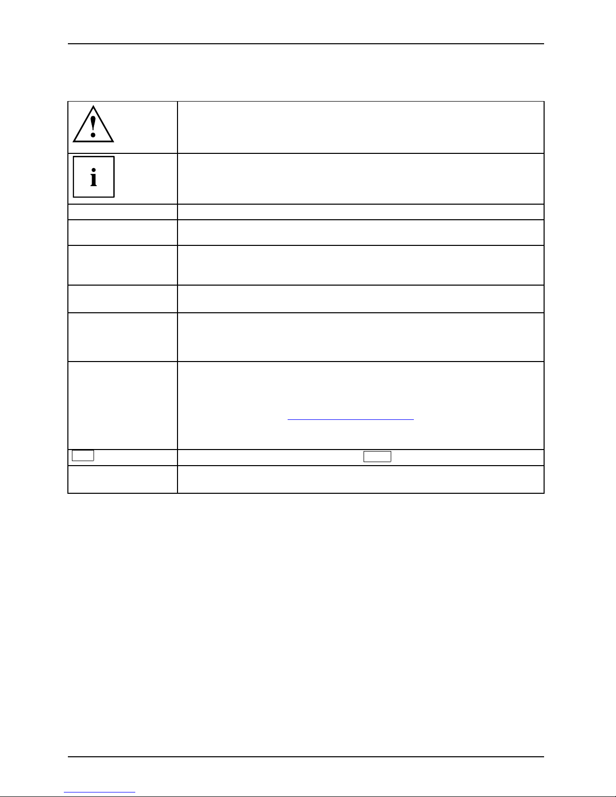
Pay particular attention to text marked with this symbol. Failure to observe
these warnings could pose a risk to health, damage the device or lead
to loss of data. The warranty will be invalidated if the device becomes
defective through failure to observe these warnings.
Indicates important informa
tion for the proper use of the device .
►
Indicates an activity t hat must be performed
Indicates a result
This font
indicates data e ntered
using the keyboard in a program dialogue or at
the command line, e.g.
your password (Name123) or a command used to
start a program (star
t.exe)
This font
indicates information that is displayed on the screen by a program, e.g.:
Installation is complete.
This font
indicates
• terms and texts used in a software interface, e.g.: Click on Save
• names of programs or files, e.g. Windows or setup.exe.
"This font"
indicates
• cross-references to another section, e.g. "Safety information"
• cross-references to an external source, e.g. a web address: For more
information, go to "
http://www.fujitsu.com/fts"
• Names of CD s, DVDs and titles or designations for other materials,
e.g.: "CD/DVD Drivers & Utilities" or "Safety/Regulations" manual
Key
indicates a key on the keyboard, e.g:
F10
This font
indicates terms a nd texts that are emphasised or highlighted, e.g.: Do
not switch off th e device
6 Fujitsu
Page 11
Important notes
Important notes
ImportantnotesNotes
In this chapter you will find information regarding safety which it is essential to
take note of when working with your device.
Safety information
SafetyinformationNote
Please note the informat
ion provided in the "Safety/regulations" manual
and in the following safe
ty notes.
When installing and ope
rating the device, please observe the notes on
environmental conditi
ons in Ch apter "
Technical data", Page 53 as well as
the instructions in Cha
pter "
Getting started", Page 11.
When setting up the dev
ice, make sure there is clearance all around it so that
thecasingreceives
enough ventilation. In order to avoid overheating, do not
cover the ventilati
on areas of the monitor or the device.
You must only opera
te the device if the rated voltage used by the
device is set to the
local mains voltage.
The main switch (if
present) and the ON/O FF switch do not disconnect the
device from the ma
ins voltage. To completely disconnect from the mains
voltage, remove t
he power plug from the power socket.
Only operate th
e device with the casing closed.
Replace the lit
hium battery on the mainboard in accordance with the instructions
in "
Replacing t
he lithium battery", Page 52.
Caution, comp
onents in the system can get very hot.
The activiti
es described in these instructions must always be
performed wi
th the greatest care.
Repairs to th
e device must only be performed by qualified technicians.
Incorrect r
epairs could put the user at great risk or cause serious damage
to the equ i
pment (electric shock, risk of fire).
Transpor
ting the device
Device,Trans po
rtation
Retrans
portation
Transport all parts separately in their original packaging or in a packaging which
protects them from knocks and jolts, to the new site.
Do not unpack them until all transportation manoeuvres are completed.
If the device is broug ht from a cold environment into the room where it will be used,
condensation may occur. Before operating the device, wait until it is absolutely dry
and has reached approximately the same temperature as the installation site.
Fujitsu 7
Page 12

Important notes
Cleaning the device
Device,Transpo rtationRetransportationSystemunit,seeDevi ce
Turn off all power and equipment switches and disconnect the power
plug from the mains outlet.
Do not clean any interior parts yourse lf, leave this job to a service technician.
Do not use any cleaning agents that contain abrasives or may corrode
plastic (alcohol, thinner or acetone).
Never clean the device with water! Water entering into th e device could
present a serious risk to users (e.g. electric shock).
Ensure that no liquid enters the system .
The surface can be clea
ned with a dry cloth. If particularly dirty, use a cloth that has been
moistened in mild dome
stic detergent and then carefully wrung out.
Use disinfectant wi
pes to clean the keyboard and the mouse.
Energy saving, disposal and recycling
DisposalEnergysavingRecyclingDrivers&UtilitiesDVDUserDocumentationDVD
You c a n find information on these subjects on the "Drivers & Utilities" DVD or on our
website ("
http://www.fujitsu.com/fts/about/fts/environment-care/").
8 Fujitsu
Page 13

Important notes
CE marking
CEmarkingCEmarkingNotesElectromagneticcompatibilityLowvoltagedirective
The shipped version of this device complies with the requirements of European Union
directives 2004/108/EC "Electromagnetic compatibility", 2006/95/EC "Low voltage directive" and
2009/125/EC "Ecodesign".
CE marking for devices with radio component
This equipment complies with the requirements of Directive 1999/5/EC of the European Parliament
and Commission from 9 March, 1999 governing Radio and Telecommunications Equipment
and mutual recognition of conformity.
The CE marking valid for your device can b e found on the device label.
Explanation: CE nnnn (!); nnnn defines the type of CE marking and the exclamation mark indicates
a device with radio components.
You c a n find more information and declarations of c onfo rmity on the Internet at:
"
http://globalsp. ts.fujitsu.com/sites/certificates".
This equipment can be used in the following countries:
Belgium Bulgaria Denmark
Germany
Estonia Finland France
Greece
UK Ireland Iceland Italy
Croatia
Latvia Liechtenstein Lithuania
Luxembourg Malta Netherlands Norway
Austria Poland Portugal Ruma nia
Sweden Switzerland Slovakia Slovenia
Spain Czech Republic
Hungary
Cyprus
Contact the corresponding government office in the respective country for current information on
possible operating restrictions. If your country is not included in the list, then please contact
the corresponding supervisory authority as to whether the use of this product is permitted in
your country.
Fujitsu 9
Page 14

Important notes
FCC Compliance Statement
If the device complies with the FCC regulations, the F CC sign can be found on the type rating plate.
FCC Class B Compliance S tate
ment
DOC (INDUSTRY CANADA) NOTICES
Notice to Users of Radios and Television:
This class B digital apparatus complies with Canadian ICES-003.
The following state ment applies to the products covered in this manual, unless otherwise specified
herein. The statement for other products will appear in the accompanying documentation.
NOTE:
This equipment has been tested and found to comply with the limits for a "Class B" digital
device, pursuant to Part 15 of the FCC rules and meets all requirements of the Canadian
Interference-Causing Equipment Standard ICES-003 for digital apparatus. These limits are
designed to provide reasonable protection against harmful interference in a residential installation.
This equipment generates, uses and can radiate radio frequency energy and, if not installed
and used in strict accordance with the instructions, m ay cause harmful interference to ra dio
communications. However, there is no guarantee that interference will n ot occur in a particular
installation. If this equipment does cause harmful interference to radio or television rece ption,
which ca n be determined by turning the equipmen t off and on, the user is encouraged to
try to correct the interference by one or more of the following measures:
• Reorient or relocate the receiving antenna.
• Increase the s
eparation between equipment and the rece iver.
• Connect the equipment into an outlet on a circuit different from th at to
which the receiver is connected.
• Consult the d
ealer or an experienced radio/TV technician for help.
Fujitsu is not responsible for any radio or tel evision interference caused by unauthorized
modifications of this equipment or the substitution or attachment of connecting cables and
equipment other than those specified by Fujitsu. The c orre ction of interferences caused by such
unauthorized modification, substitution or attachment will be the responsibility of the user.
The use of shielded I/O cables is required when connecting this equipment to any and all optional
peripheral or host devices. Failure to do so may violate FCC and ICES rules.
FCC Radiation Exposure Statement
This equipment complies with FCC radiation exposure limits set forth for an uncontrolled environment.
The transmitters in this device must not be co-located or op erated in conjunction
with any other antenna or transmitter.
To prevent radio interference to t he licensed service, this device is intended to be
operated indoors and aw ay from windows to provide maximum shielding. Equipment (or
its transmit antenna) that is installed outdoors is subject to licensing.
Users are not authorized to modify this product. Any modifications invalidate the w arranty.
This equipment may not be modified, altered, or chan ged in any way without signed
written permission from Fujitsu. Unauthorized modification will void the equipment
authorization from the FCC and Industry Canada and the warranty.
10 Fujitsu
Page 15
Getting started
Getting started
Gettingstarted
Please observe the safety information in the "Important notes", Page 7 chapter.
Unpacking and checking the delivery
It is recommended not to throw away the original packaging material! It may be
required for reshipment at some later date.
PackagingContentso fdeliveryPackaging,
► Unpack all the individual parts.
► Check the contents of the package for any visible damage caused during transport.
► Check w heth er the delivery conforms to the details in the delivery note.
► Should you discover that the delivery does not correspond to the delivery
note, notify your local sales outlet immediately.
Steps for initial setup
Preparingforfirstuse, overviewPreparingforuse,
Only a few steps are necessary to put you r new device into operation for the first time:
• Select a location for device and set up device
• Connect external devices such as mouse, keyboard and monitor
• Check the voltage at the mains outlet and connect the device to an elect rical outlet
• Switch the device on
You will learn more about the individual steps in the following sections.
External devices
If you have received other external devices in ad dition to your own device (e.g.
a printer), do not connect these until after the initial installation. The following
sections describe how to connect these external devices.
Drives and boards
If you have received drives or boards with your device, please do not install
them until after first-time setup. How to install drives and boards is described
in the "
System expansions", Page 32 chapter.
Fujitsu 11
Page 16

Getting started
Setting up the device
WorkstationErgonomicDevi ce
When installing your device, please read the recommendations and safety
notes in the "Safety/regulations" manual.
We recommend that you place your device on a surface which is not slippery. In
view of the man y different finishes and varnishes used on furniture, it is possible
that the rubber feet will mark the surface they stand on.
Depending on the location of your device, bothersome vibrations and noises may
occur. To prevent this, a distance of at least 10 mm / 0.39 inch should be maintained
from other devices on casing sides w ithout ventilation surfaces.
In order to avoid overheating, do not cover the ventilation areas
of the monitor or the device.
A minimum distance of 200 mm / 7.87 inch from the device must
be observed for ventilation areas.
Do not stack several devices on top of each other.
Do not expose the device to extreme ambient conditions (see "
Technical data", Page 53,
section "Ambient conditions"). Protect the device against dust, humidity and heat.
12 Fujitsu
Page 17
Getting started
Operating position
You can use the device in a v ert ical or horizontal operating position.
Vertical operating position
(optional)
Operation in the vertical operating position i s not allowed in Taiwan.
Proceed as follows to operate the device in the vertical operating position:
Verticaloperatingpo
sition
Operatingposition,v
ertical
Rubber/plasticfeetSidecover
► Disconnect the cables if required.
► Pull off the foil from the rubber/plastic feet included in the pack of accessories.
► Stick the rubber/plastic feet to the underside of the casing. In order to ensure a
that the unit is stable, the rubber/plastic feet should be located in approximately
the positions shown in the illustration.
► Place the device vertically on the rubber/plastic feet.
► If necessary, reconnect any cables that were previously disconnected.
Fujitsu 13
Page 18
Getting started
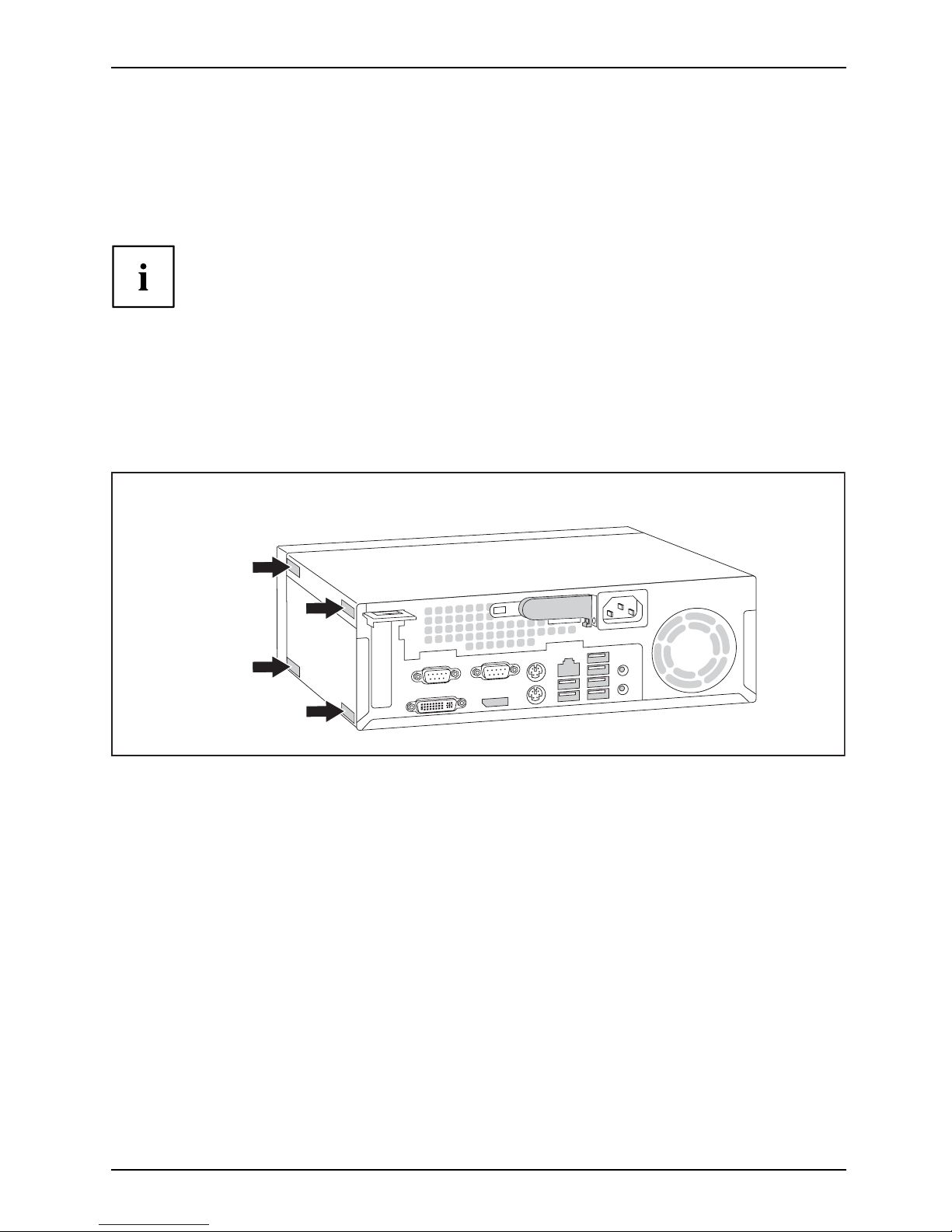
Horizontal operating position with rubber/plastic feet
HorizontaloperatingpositionOperatingposition,horizontalRubber/plasticfeet
The horizontal operating position is only permitted with the rubber/plastic
feet (due to the heat generated on the underside).
► If necessary, disconnect the cables.
► Place the device on its upper side on a sturdy, flat and clean surface.
► Stick the rubber/plastic feet (1) to the
underside of the casing.
► To ensure a that the device is stable,
the rubber/plastic feet should be fixed
in similar positions to the ones shown
in the illustration.
► Place the device on the rubber/plastic feet.
► If necessary, reconne ct any cables that
were previously disconnected.
14 Fujitsu
Page 19

Getting started
Connecting the device to the mains voltage
DeviceConnectingDevice
► Check the voltage setting.
2
1
► Connect the power cable to the device.
► Plug the powe r plug into a properly grounded mains outlet.
The device is fi tted with a wide voltage range power supply. T his means you
do not need to set the nominal voltage manually for these de vices. Therefore
there is no switch available for the voltage setting.
Fujitsu 15
Page 20

Getting started
Connecting external devices
Read the documentation on the external device before connecting it.
With the exception of USB devices, always remove all power plugs
before connecting external devices!
Do not connect or disconnect cables during a thunderstorm.
Always take hold o f the actual plug. Never unplug a cable by pulling the cable itself.
Connect and disco nnect the cables in the order described below.
Connecting the cables
► Turn off all power and equipm ent switches.
CordCable,
► Remove all power plugs from the grounded mains outlets.
► Connect all the cables to the device and the external devices. Please make sure that you
always observe the safety notes provided in "
Important notes", Page 7.
► Plug all data communication cables into the appropriate sockets.
► Plug all power cables into the grounded mains outlets.
USB devices are hot-pluggable. This means you can connect and disconnect
USB cables while your device is switched on.
Additional information can be found in "
Connecting external devices to the USB
ports", Page 19 and in the documentation for the USB de vices.
Disconnecting the cables
► Sw itch off al
l affected devices.
Cable,
► Remove all power plugs from the grounded mains outlets.
► Unplug all d
ata communication cables from the appropriate sockets.
► Disconnect all o f the cables from the device and from the external devices.
16 Fujitsu
Page 21

Getting started
Ports on the device
PortsExternaldevicesDevice
The ports are located on the front and back of the device. The ports available o n your
device depend on the configuration level you have selected. The standard port s are
marked with the symbols shown below (or similar). Detailed information on the location
of the ports is provided in the manual for the mainboard.
PS/2 keyboard port, purple
Keyboardport
Parallel port/printer (optional)
ParallelportPrinter
1
Serial port 1, turquoise
Serialport
2
Serial port 2, turquoise
Serialport
VGA monitor connection, blue
Monitorport
Microphone jack, pink
Microphonejack
Headphones jack, light green
Headphones
Audio input (Line in), light blue
AudioinputLinein
Audio output (L ine out), light
green
AudiooutputLineout
PS/2 mouse port, green
MouseportPS/2mouseport
USB 2.0 - Universal Serial Bus,
black
UniversalSerialBus
USB 3.0 - Universal Serial Bus,
blue
LAN
LAN port
LANport
DVI-I monitor port DP DisplayPort
Some of the connected devices require special software (e.g. drivers) (refer to the
documentation for the connected device a nd operating system).
Connecting a monitor
► Follow the instructions contained in the monitor manual to prepare the
monitor for use (e.g. connect the cables).
Monitor
► Plug the data cable into the monitor port on the device.
Depending on the configuration level of you r device and your monitor, you can
connect the data cable either to the DVI interface or t o the DisplayPort.
► Plug the mo nitor power cable into a grounded mains outlet.
Fujitsu 17
Page 22

Getting started
Connecting the mouse
You can connect a USB mouse or a PS/2 mouse to your device.
Mouse,Connecting,
Connecting a USB mouse
► Connect the USB mouse to one of the USB ports on the device.
USBport,USBport
Connecting a PS/2 mouse
The PS/2 mouse is only detected by the device if you connect the mouse when
the device is switched off and then switch the device on again.
► Sw itch your device off.
If you do not attach a m ouse to the PS/2 mouse port, you can disable the mouse
controller in the BIOS Setup in order to free the IRQ12 for a different a pplication.
► C onnect the PS/2 mou
se to the PS/2 mouse port of the device.
PS/2mouse,Connecting,PS/2mouse,
► Switch your device on again.
Connecting the keyboard
You can connect a USB keyboard or a PS/2 keyboard to your device .
Keyboard,Conne cting,
Connecting a USB keyboard
Use the supplied keyboard cable only.
USBport,Connecting,
► Plug the rectangular co nnector of the keyboard cable into the rectangular socket
on the underside or on the rear of the keyboard.
► Insert the flat rectangular USB plug of the keyboard cable into one of the device’s USB ports.
USBport
Connecting a PS/2 keyboard
Use the supplied keyboard cable only.
Connect
ingaPS/2keyboard
Connect
ing,
The PS/2 keyboard is only detected by the device if you connect the keyboard
when the device is switched off an d then switch the device on again.
► Sw itch yo
ur device off.
► Plug the rectangular co nnector of the keyboard cable into the rectangular socket
on the underside or on the rear of the keyboard.
► Plug th
e round plug of the keyboard cable into the keyboard po rt on the device.
Keyboard,
► Switch your device on again.
18 Fujitsu
Page 23

Getting started
Connecting external devices to the parallel
(optional) or serial port
ParallelportSerialportParallelportSerialportExternaldevicesDevices
External devices can be connected to the parallel or serial port (e.g. a printer or a modem).
► Connect the data cable to the external device.
► Depending on the device, conn
ect the data cable to the parallel port or the serial port.
For an exact description o
f how to connect external devices to the corresponding
port, please refer to the d
ocumentation of the external device.
Port settings
ParallelportSerialport,
You can change the port settings (e.g. address, interrupt) in the BIOS Setup.
Device drivers
DevicedriversDevicedrivers,
The devices conn ected to the parallel or serial port require drivers. Your operating
system already includes many drivers. If the required drive is missing, install it. Current
drivers are usually available on the Internet or will be supplied on a data carrier.
Connecting external devices to the USB ports
USBdevices,USBport,Externaldevices,Devices,
You can connect a wide range of external devices to the USB ports (e.g.
printer, scanner, mod em or keyboard).
USB devices a re hot-pluggable. This means you can connect and disconnect
USB cables while your device is switched on.
Additional information can be found in the documentation for the USB devices.
► Connect the data cable to the external device.
► Connect the data cable to one of the USB ports on your device.
Device drivers
The external USB devices you connect to the USB ports usually require no driver of their
own, as the required software is already included in the operating system. If the device
requires separate software, please note the information in the manufacturer’s manual.
To ensure the transmission capacity of USB 2.0, the cable from the external USB device
to the USB port of y our device must not be longer than 3 m / 118.11 in.
Fujitsu 19
Page 24

Getting started
Switching on for the first time: installing the software
Installing,Software,Installing,
Once the installation has been started the device must not be switched
off, unless the installation has been completed.
During installation, the device may only be rebooted when you are requested to do so!
The installation will oth erwise not be carried out correctly and the contents
of the hard disk must be completely restored.
If the device is integrat
ed into a network, the user and server details as well as
the network protocol ar
e r equired during the software installation.
Contact your network ad
ministrator if you have any questions about these settings.
When you switch on the d
evice for the first time, the supplied software
is installed and config
ured. Plan a reasonable amount of time for this,
as this process must n
ot be interrupted.
You may need the lic
ence number for Windows during the installation. The licence
number is located o
n a label on your de vice.
Switch on the monitor and the machine
In order to avoid overheating, do not cover the ventilation areas
on the monitor or the device.
► Switch on the monitor (see operating instructions for the monitor).
► Press the on/off button on the front of the machine.
The operational display will light up and the machine will sta rt.
20 Fujitsu
Page 25

Getting started
Installing the software
► During inst allation, follow the on-screen instructions.
Software,I nstalling,
► If anything is unclear regarding the data you are asked to input, read the
online Help in your operating system.
You will find more information on the system, as well as drivers, utilities and updates on
the "D rivers & Utilities" DVD and on the Internet at "
http://www.fujitsu.com/fts/support".
You can find information and help on the Windows operating system functions
on the Internet at "
http://windows.microsoft.com".
Fujitsu 21
Page 26

Operation
Operation
Switch the device on
► If necessary, switch the monitor on (see the operating manual for the monitor).
DeviceMonitor
► Press the ON/OFF switch on t
he front of the device.
The power indicator glows and the device is s tart ed.
Switching off the device
► Shut down the operatin
g system properly.
DeviceMonitor
► If the ope rating system does not automatically switch the device into power-saving mode
or switch it off, press the ON/OFF switch for at least 4 seconds.
The device then con
sumes a minimum amount of energy.
The ON/OFF switch d
oes not fully disconnect the TV from the mains voltage. To
completely disco
nnect the mains voltage, remove the po w er plug from the power socket.
► If necessary, switch the monitor off (see the operating manual for the monitor).
22 Fujitsu
Page 27

Operation
Indicators on the device
Indicators,Device
The indicators are located on the front of the casing. Which indicators are available on
your device depends on the configuration level you have selected.
1 3 42
No. Indicator Description
1 Power indicator
Caution: When en
ergy saving mode is active, the device must
not be switched
off at the main power switch (if present) or
disconnected f
rom t he mains, as this may result in data loss.
• The indicator i
s illuminated: The device is sw itched on.
• The indicator is flashing: The device is in energy-saving
mode. After being switched on with the power button, the
device switches on or returns to the state it was in b efore the
energy-saving mode.
• The indicat
or is not illuminated: The device is disconnected
from the mai
ns or is ready. If the device is ready it can be
switched o
n with the ON/OFF switch.
2Harddiski
ndicator
The indicator lights u p when the hard disk drive of the device is
accessed.
3 Drive indicator The indicator lights up when the DVD drive in the device is being
accessed. Never remove the DVD while the indicator is illuminated.
4
SmartCard reader
indicator (optional)
The indicator is lit if a SmartCard reader is installed.
The indicator flashes when data is being exchanged.
Fujitsu 23
Page 28

Operation
Keyboard
KeyboardKeyboard,Keyboard,Keyboard,Keyboard,Keyboard,AlphanumerickeypadCursorkeysKeys,FunctionkeysNumerickeypadNumerickeypad
The illustrated keyboard is an example and may differ from the model you use.
1 2
345
1 = Function keys
2 = On/off switch (optional)
3 = Alphanumeric keypad
4=Cursorkeys
5 = Numeric keypad (calcu lator keypad)
Important k
eys and keyboard shortcuts
KeysKeyboardshortcuts
The description of the following keys and keyboard s hortcu ts applies to Microsoft
operating systems. Details of other keys and keyboard shortcuts can be found in
the documentation for the relevant application program.
Key / key combination Description
ON/OFFswi
tch
Button,
On/off sw itch (optional)
Depending on the setting in the BIOS Setup, the device can be switched
on or off with this switch. Some operating systems allow you to configure
additional functions of the ON/OFF switch in the Control Panel.
WithsomekeyboardstheON/OFFswitchcanonlybeusedwithanACPI
(Advanced Configuration and Power Management Interface). Otherwise
the key is inoperative. The mainboard must support this function.
Keys,Keys,Keys,
Enter key
confirms the highlighted selection. The Enter key is also referred to as
the "Return" key.
24 Fujitsu
Page 29

Operation
Key /key combination Description
Keys,
Windows key (device-d ependent
:variant1)
calls up the Windows S tart menu
.
Keys,
Menu key (device-depend ent:
variant 1)
calls up the menu for the marke
d item (Windows).
Keys
Windows key (device-depe
ndent: v ariant 2)
Switches bet ween the star
t screen and the last used application.
Keys
Menu key (device-depend ent: variant 2)
Opens the menu for the active application.
Keys,Keys,
Shift key
enables upper-case
letters an d the upper key symbols to be displayed.
Keys,
Alt Gr key (country
-dependent)
produces a charac
ter shown on the bottom right of a key (e.g. the @
sign on the
Q
key).
Keys,
Num Lock key
By pressing the
Num Lock key you switch between the upper- and
lower-case lev
els of the calculator keypad.
When the Num Lo
ck indicator is lit the numeric keypad and arithmetic
keys are activ
e.
When the Num L
ock indicator is not lit th e cursor control functions on th e
Numeric keyp
ad are active.
Ctrl
Keys,KeysKeysKeys,
Ctrl key
performs a special operation when pressed in conjunction with another
key. The
Ctrl
key is also called the "Control" or "Control key".
AltCtrl
Del
++
Ctrl+Alt+DelCtrl+Alt+DelKeyskeyboardshortcuts
Windows Security/Task Manager
This key combination opens the Windows Security/Task Manager window.
Settings in BIOS Setup
BIOSS
etup,
Syste
msettings,
BIOSS
etup,
BIOSS
etup,
BIOSS
etup
Setup
,
In BIOS Setup, you can set the system functions and the hardware configuration of the device.
When the PC is delivered, the default entries are valid (see "BIOS Setup" manual or manual for
the mainboard). You can customise these settings to your requirements in the BI O S Setup.
Fujitsu 25
Page 30

Operation
Property and data protection
PropertyprotectionDataprotectionSecuritym easures
Software functions and mechanical locking offer a broad range of functions for protecting your
device and your personal data from unauthorised access. You can also combine t hese functions.
Anti-theft protection
Anti-theftprotectionSecurityLockMicroSavers
1 2
1 = Security Lock 2 = Holes for padlock
You can protect your device against theft
• with the Security L ock device (1) and a Kensington MicroSaver. You can only attach
the Security Lock if the sliding locking mechanism is set to the left, thereby locking
the casing. Please consult the ma nual for your Security Lock.
• with the holes (2), a padlock and a chain, which you have connected to a fixed object beforehand.
BIOS setup security functions
Securityfunctions,BIOSSetup,
The Security menu in BIOS Setup offers you various options for protecting your
personal data against unauthorized access, e.g.:
• Preventing unauthorised access to BIOS Setup
• Preventing unauthorised system access
• Preventing un authorised access to the settings of boards with their own BIOS
• Issuing virus warnings
• Protecting BIOS from overwriting
• Protecting the device from being switched on by an external device
You can also combine these functions.
You will find a detailed d escription of the Security menus and how to assign passwords
in the manual for the mainboard or in the "BIOS Setup" manual.
26 Fujitsu
Page 31

Operation
Access authorization via SmartCard (optional)
Securityfunctions,Accesspermission,SmartCard
In systems equipped with a SmartCard reader, access can be restricted to those
users who have a corresponding SmartCard.
Fujitsu 27
Page 32

Troubleshooting and tips
Troubleshooting and tips
Refer to the safety notes in the "Safety/regulations" manual and in the "Getting
started", Page 11 chapter when connecting or disconnecting cables.
If a fault occurs, try to c
orrect it as described in the following documentation:
• in this chapter
• in the documentation for the connected devices
• in the help systems of th
esoftwareused
• in the documentation for your operating system
Help if problems occur
Should you encou nt
er a problem with your computer that you cannot resolve yourself:
► Note the ID number
of your device. The ID number is found on the type rating
plate on the back,
the underside or the top of the casing.
► F o r further clarification of the problem, contact the Service Desk for your country (see the
Service Desk list or visit the Internet at "
http://support.ts.fujitsu.com/contac t/servicedesk"). When
you do this, please have ready the identity number and serial number of your system.
Troubleshooting
Power-on indicator does not light up after the
device is switched o n
Cause Corrective measure
The mains power supply is faulty. ► Check whether the power cable is properly
plugged into the device and into a grounded
mains outlet.
► Switch the device on.
Internal power supply overloaded.
► Pull the
power plug for the device out of the
grounde
d mains o utlet.
► Wait for a moment.
► Plug th
e power plug back into a grounded
mains
outlet.
► Switch the device on.
28 Fujitsu
Page 33

Troubleshooting and tips
The device cannot be switched off with the ON/OFF switch.
Cause
Remedy
System crash ► Ke ep the on/off switch pressed for at least 4
seconds until the machine switches off.
Caution: This can lead to a loss of data!
This procedure does not allow the operating
system to shut down in an orderly way. The next
time the system is started there may well be
error messages.
Monitor remains blank
Cause
Remedy
Monitor is switched off ► Sw itch your monitor on.
Power saving has been activated (screen is
blank)
► Press any key on the keyboa rd.
or
► Deactivate the screen saver. If
necessary, enter the appropriate
password.
Brightness control is set to dark ► Adjust the brightness control. For detailed
information, please refer to the operat ing
manual supplied with your monitor.
Power cable not connected
► Sw itch off the monitor and the device.
► C heck that the monitor power cable is
properly connected to the monitor and to
a grounded mains outlet or to the monitor
socket of the device.
► Check that the device power cable is
properly plugged into the device and a
grounded mains outlet.
► Switch on the monitor and the device.
Monitor cable not connected
► Sw itch of
f the monitor and the device.
► Check that the monitor cable is properly
connected to the device and monitor.
► Sw itch o
n the monitor and the device.
Incorrect setting for the monitor
► Restar
t the system.
► Press
F
8
while the system is booting.
► Start
the system in Safe Mode.
► Se t up the monitor as described in the
documentation for your operating system
and monitor.
Fujitsu 29
Page 34

Troubleshooting and tips
No mouse pointer displayed on the screen
Cause
Troubleshooting
The mouse is not correctly connected.
► Shut down the operating system properly.
► Switch the device off.
► Check that the mouse cable is properly
connected to the system unit. If you use an
adapter or extension lead with the mouse
cable, check the connections.
► Make sure that only one mouse is
connected.
► Switch the device on.
Time and/or date is not correct
Cause
Remedy
Time and date are incorrect.
► Set the correct time and date within the
operating system you are using.
or
► Set the correct time and/or date in the
BIOS Setup.
The lithium battery is discharged.
► If the time and date are repeatedly wrong
when you switch on your device, replace the
lithium battery (see "
Replacing the lithiu m
battery", Page 5 2).
Error messages on the screen
Error m essa ges and their explanations are provided:
• in the technical manual for the mainboard
• in the documentation for the pro grams used
Installing new software
When installing programs or drivers, important files may be overwritten and modified. To
be able to access the original data in the event of any problems following installation,
you should backup your hard disk prior to installation.
Restoring the hard disk contents
You will find the instructions for restoring the contents of the hard disk in the "R eco very Guide" manual.
30 Fujitsu
Page 35

Troubleshooting and tips
Tips
Topic Tip
Outofsystemresources ► C lose u nnecessary applicatio
ns.
or
► Run the applications in a different order.
Other manuals Further manuals are provid
ed as PDF files on
the "Drivers & Utilities"
DVD.
Fujitsu 31
Page 36

System expansions
System expansions
Upgrades,Device,SystemexpansionComponentsServicing
Repairs to the device must only be performed by qualified technicians. Incorrect repairs
may greatly endanger the user (electric shock, fire risk) and will invalidate your warranty.
After consulting the Hotline/Help Desk, you may remove and install the components
described in this manua l yourself.
As the device has to be shut down in order to install/deinstall system hardware
components, it is a good idea to print out the relevant sections of this chapter beforehand.
The following illustrations may differ slightly from your device, depending on its configuration level.
If further documentation was delivere d with your device, please also read this through carefully.
In addition, before removing or installing system components, please pay attention to the following:
The device must be switched off when installing/removing the system
expansions and may not be in energy-saving mode.
Remove the power plug before opening the device.
Be careful that no wires become trapped when removing or installing components.
When installing components that become very hot, make sure that the maximum
permissible temperature of the components in operation is not exceeded.
An update of the BIO S may be required for a system expansion or hardware
upgrade. Further information can be found in the BIOS help section or if
necessary in the Technical Manual for the mainboard.
32 Fujitsu
Page 37

System expansions
Information about boards
Take care with the locking mechanisms (catches and centring pins) when you
are replacing boards or components on boards.
Note that some components on the mainboard may be very hot if the device was
in use shortly before the casing was removed.
To prevent damage to the board or the components and conductors on it, please take care when
you insert or remove boards. Make sure expansion boards are inserted straightly.
Never use sharp objects (screwdrivers) for leverage.
Boards w ith electrostat
ic sensitive devices (ESD) are identifiable by the label
shown.
When hand ling boards fit
ted with ESDs, you must alw ays observe the
following points:
• You must always disc
harge static build up (e.g. by touching a grounded
object) before work
ing.
• The equipment and tools you use must be free of static charges.
• Only touch or hold t
he boards by the edge or, if present, at the areas
marked green (Touc
h Points).
• Never touch pins or conductors on boards fitted with ESDs.
Fujitsu 33
Page 38

System expansions
Opening the casing
Please read the relevant safety notes in "Important notes".
Disconnect the power plug from of the mains outlet.
Only re-insert the power plug aft er you have closed the casing.
► Sw itch the device off.
The device must not be in p
ower-saving mode.
► R emove any connected w
ires which are in the way.
► Place the casing in a convenient working position.
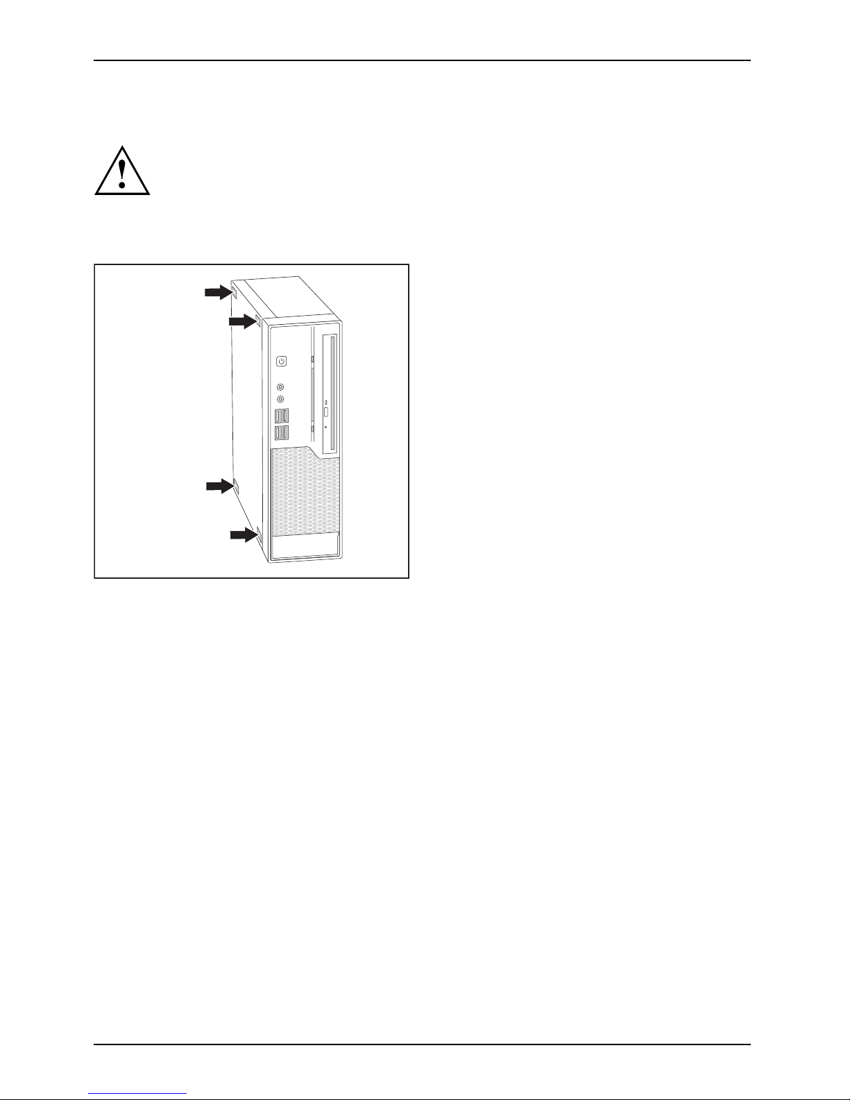
► O n devices with a cas
ing lock: Unlock the casing.
► Push the sliding locking mechanism past
aslightresistanceinthedirectionofthe
arrow to unlock the housing.
1
2
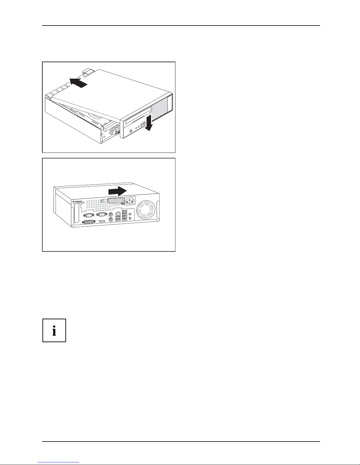
► Push the casing top cover as far as it will
go (approximately 20 mm/0.79") in the
direction of the arrow (1) a nd lift it off at an
angle in the direction of the arrow (2).
34 Fujitsu
Page 39
System expansions
Closing the casing
2
1
► Position the upper part of the casing from
above in the direction of the arrow (1) onto
the lower part of the casing so that the
distance to the rear edge of the casing
is approximately 20 mm/0.79".
► Push the upper part of the casing in the
direction of the arrow (2) until it engages.
► To lock the casing, push the sliding
locking mechanism back in the direction
of the arrow until it engages.
► Lock the casing again if necessary.
► On devices with a casing lock: Lock
the casing.
► Reconnect the cables that you
disconnected previously.
Overview of the drive bays and drives in your device
The casing
has space for several accessible and non-accessible drives:
• one drive b
ay for an accessible 5
1
/4inch drive (Slim Line) as well as a SmartCard reader (optional)
• one drive bay for a non-accessible 3
1
/2inch drive as well as a compact flash module (optional)
"Accessible drives" are e.g. DVD or CD ROM drives, into which a data medium can be
inserted from outside. "Non-accessible drives" are for example hard disk drives.
Fujitsu 35
Page 40

System expansions
Installing and removing plasti
c drive covers
Removing the plastic drive cover
Do not throw away the covers. If you remove the drive again later, you will need to fitthe
covers again (cooling, fire protection or EMC regulations which need to be complied with).
Ifyouwishtoinstallanaccessibledriveinanemptybay,youmustfirst remove the plastic drive cover.
► O pen the casing (see "
Opening the casing", Page 34).
► La y the casing cover within easy reach on a non-slip surface.
► Gently press the latches of the relevant
plastic drive covers forwards and, working
from the outside, pull the plastic drive
covers out of the front cover.
36 Fujitsu
Page 41

System expansions
Installing the plastic drive cover
Depending on the drive, e.g. if you wish to remove the accessible drive, you may
need to re fit the plastic drive cover again afterwards.
► Insert the drive cover in the direction
of the arrow into the f ront panel
and press the latches lightly into the
corresponding brackets.
► Close the casing (see "
Closing the
casing", Page 35).
Installing and removing the drive cage
Removing the d
rive cage
Drivecage
► Open the casing (see "Opening the casing", Page 34).
1
2
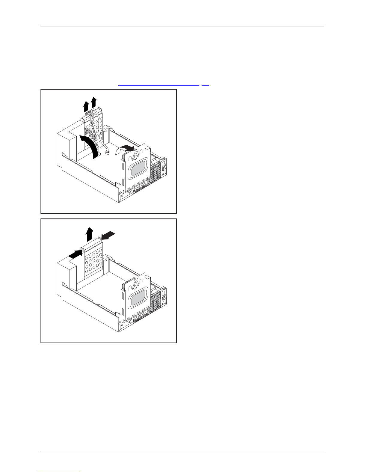
► Fold up the dri
ve cage at an angle (1).
► If a drive is present, disconnect t he
connector of the data and power supply
cables from the drive (2).
► Ta k e o u t t h
e drive cage from the
casing mou
nts.
Fujitsu 37
Page 42

System expansions
Installing the drive cage
Drivecage
► O pen the casing (see "Opening the casing", Page 34).
2
1
► Push the drive cage at an angle into
the casing m ounts (1).
► If a drive is present, connect the connector
of the data and power supply cables (2).
► Close the drive cage.
► Close the casing (see "
Closing the
casing", Pa ge 35).
Installing and removing the accessible 51/4inch drive
Removing an accessible drive
► O pen the casing (s
ee "
Opening the casing", Page 34).
► Remove the drive cage (see "
Removing the drive cage", Page 37).
1
1
1
2
► Remove the screw
s from the drive c age (1).
► Takethedriveoutofthedrivecage(2).
► Install the dri
ve cage again (see "
Installing
the drive cage
", Page 38).
► If you do not want to install a new drive, you
must refit the plastic drive cover again (see
"
Installing the plastic drive cover", Page 37).
► C lose the c
asing (see "
Closing the casing", Page 35).
38 Fujitsu
Page 43

System expansions
Installing an accessible d rive
► Open the casing (see "Opening the casing", Page 34).
Do not throw a way the covers. If you remove the drive again, you must reinstall the
covers (c ool ing, fire protection or EMC regulations to be complied with).
You must only use the screws recommended by the man ufacturer. Long screws
could damage the drive or prevent it from working properly.
EMC,electromagneticcompa tibility
► If necessary, remove the plastic drive cover (see "Removing the plastic dr ive cover", Page 36).
► Remove the drive cage (se
e "
Removing the drive cage", Page 37).
2
2
2
1
► Slide the n ew drive as far as it will go
into the drive cage (1).
► Fasten the screws (2).
► Install t he drive cage again (see "
Installing
the drive cage", Page 38).
► Con nect the connect
or for the data and
power cables to the d
rive.
► Close the casing (see "
Closing the casing", Page 35).
It may be necessary to mo dify the entry for the drive in the BIOS Setup accordingly.
Fujitsu 39
Page 44
System expansions
Installing and removing the har
ddiskdrive
Removing the hard disk drive
► O pen the casing (see "Opening the casing", Page 34).
1
2
3
3
► Fold up the drive cage (1).
► If there is a drive in the drive cage,
disconnect the data and power supply
cables from the drive.
► Fold up the hard disk cage (2).
► Pull the data and power supply cable
off the hard disk (3).
1
1
2
► Press the two ends of th e EasyChange
rails together (1) and pull out the
hard disk drive (2).
40 Fujitsu
Page 45

System expansions
► Release the die EasyChange rails
from the hard disk.
If you do not want to install a new hard disk, keep the EasyChange
rails for a future installation.
► Close the casing (see "
Closing the casing", Page 35).
Installing the hard disk drive
Inoperable 2 1/2 inch drives of type HDD or SSD can be secured via a 3 1/2 inch
installation adapter via EasyChange rails or can be screwed directly into the drive cage.
► Open the casing (see "
Opening the casing", Page 34).
► Attach the EasyChange rails to the hard disk.
► Fold up t
he hard disk cage.
Fujitsu 41
Page 46

System expansions
1
► Slide the hard disk together with the
EasyChange rails into the bay until you
feel the hard disk engage(1).
1
1
3
2
► Attach the data and the power supply
connectors at the hard disk drive (1).
► If necessary also a
ttach the data
cable at the main bo
ard. Refer to the
manual for the main
board.
Do n ot connect any cables.
► F old the hard disk cage downwards (2).
► F old down the drive cage (3).
► Close the casing (see "
Closing the casing", Page 35).
It may be necessary to modify the entry f or the drive in the BIOS Setup.
42 Fujitsu
Page 47

System expansions
Installing and removing a Compact Flash
module (optional)
Installing the Compact Flash module
CompactFlashmodule
► Open the casing (see "Opening the casing", Page 34).
► Swing up the drive cage.
► If there is a drive in the drive cage, disconnect the data and power supply cables from the drive.
1
11
► Secure the Compact Flash module with
the screws (1) to the carrier.
1
► Slide the Compact Flash module with the
EasyChange rails into its bay until the
carrier noticeably engages (1).
► Connect the connector for the data and power cables to th e Compact Flash module.
► Fold do
wn the drive cage.
► Close the casing (see "
Closing the casing", Page 35).
Fujitsu 43
Page 48

System expansions
Removing the Compact Flash module
CompactFlashmodule
► O pen the casing (see "Opening the casing", Page 34).
► F o ld up the drive cage.
► D isconnect the Compact Flash cable connector from the mainboard. Refer
to the manual for the mainboard.
1
1
2
► Press the two ends of th e EasyChange
rails together (1) and pull out the
hard disk drive (2).
1
1
1
► Loosen the screws (1).
► Remove the Compa
ct Flash module
from its bay.
► F old down the hard disk cage (2).
► C lose the c
asing (see "
Closing the casing", Page 35).
44 Fujitsu
Page 49

System expansions
Installing/removing a SmartCard reader (optional)
Operation of this module is not permitted in Taiwan.
In systems equipped with a SmartCard reader, access can be restricted to those
users who have a corresponding SmartCard.
Installing the SmartCard reader
SmartCardreader
► Open the casing (see "Opening the casing", Page 34).
► Break out the web at the SmartCard opening on the front cover.
2
2
1
► Remo ve the drive cage (see "Removing
the drive cage", Page 37)
► Slide the Sma rtCard reader into the
bay provided for it (1) and secure it
with the two screws (2).
► Make sure that the SmartCard re ader
is also between the two brackets.
Otherwise, you will not be able to insert
the SmartCard from outside.
► Connect the cable for the Smart Card reader to the mainboard and the SmartCard
reader. Refer to the manual for the mainboard.
► Install the drive cage again (see "
Installing the drive cage", Page 38).
► Close the casing (see "
Closing the casing", Page 35).
Removing the SmartCard reader
SmartCar
dreader
► Open the ca
sing (see "
Opening the casing", Page 34).
1
1
2
► Remo ve the drive cage (see "Removing
the drive cage", Page 37)
► Disconn
ect the Smart Card connector
from the
mainboard. Refer to the
manual
for the mainboard.
► Loosen the screws (1).
► Pull th
e SmartCard reader out of th e bay (2).
► Install t he drive cage again (see "
Installing
the drive cage", Page 38
► Clos
e the casing (see "
Closing the
casi
ng", Page 35).
Fujitsu 45
Page 50

System expansions
Installing and removing a WLAN module (optional)
WLANmodule
Operation of this module is not permitted in Taiwan.
You can also install a WLAN module for wireless LAN (Local Area Network)
in the bay of the folded-open drive cage.
Installing the WLAN module
► O pen the casing (see "Opening the casing", Page 34).
► Remove the drive cage (see "
Removing the drive cage", Page 37).
2
2
1
► Slide the WLAN module carefully into the designated bay (1) and secure it w ith the two screws (2).
Make sure that you do not scratch the antenna on the front opening of the drive cage.
► C onnect th
eUSBcabletotheWLANmodule.
► C onnect the USB cable of the WLAN module onto the corresponding connector
on the mainboard. Refer to the manual for the mainboard.
► Install t
he drive cage again (see "
Installing the drive cage", Page 38).
► Close the casing (see "
Closing the casing", Page 35).
Details on using Wireless LAN can be foun d in the online help system
included with the Wireless LAN software.
46 Fujitsu
Page 51

System expansions
Removing the WLAN module
► Open the casing (see "Opening the casing", Page 34).
► Remove the drive cage (s ee "
Removing the drive cage", Page 37).
► Disconnect the USB cable of the WLAN module from the connecto r on the
mainboard. Refer to the manual for the mainboard.
1
1
2
► R e m ove the screws (1).
► Pull the WLAN module out of the bay (2)
together with the US B cable.
Make su re that you do not scratch the antenna on the front opening of the drive cage.
► Install the drive cage again (see "
Installing the drive cage", Page 38).
► Close the casing (see "
Closing the casing", Page 35).
Installing an
d removing a board
Please read the section "Notes on boards".
You can only install low-profile boards.
To install a board please follow the ste ps b elow.
• Opening the retaining clip for the board
•Instal
ling a board
• Closing the retaining clip
You wi
ll learn more about the individual steps in the following sections.
Fujitsu 47
Page 52

System expansions
Installing a board
Do not throw the slot cover away. If you remove the board again, you
will need to install the slot co ver again (cooling, fire protection or EMC
regulations which need to be complied with).
► O pen the casing (see "
Opening the casing", Page 34).
1
► Slide the slot cover upward out of
thecasing(1).
► Make the required settings on the board.
1
►
Guide the board into the slot recess (1).
Ensure that it engages.
► If necessary, connect the cables
to the module.
► Close the casing (see "
Closing the
casing", Pa ge 35).
48 Fujitsu
Page 53

System expansions
Removing boards
► Open the casing (see "Opening the casing", Page 34).
► Remove the heat sink (see "
Removing the heat sink", Page 50).
1
► If necessary, unplug any cables which
are connected to the board.
► If you are installing a PCI Express x16
card: Release the board.
► Remove the board from the casing (1).
► If you do not want to install a new
board, reinstall the slot cover.
1
► Slide the slot cover downward into the
rear panel of the casing (1).
► Reinstall the h
eat sink (see "
Installing
the heat sink",
Page 50).
► Close the casing (see "
Closing the
casing", Page 35).
If you have installed or removed a PCI board, check the relevant PCI
slot settings in the BIOS Setup. Change the settings as required. F urther
information is provided in the PCI board documentation.
Fujitsu 49
Page 54

System expansions
Installing and removing heat si
nks
Removing the heat sink
The shape and position of the heat sink are device-dependent.
► O pen the casing (see "
Opening the casing", Page 34).
► F or processors > 65 W: Disconnect the cable of the fan (FAN1) from the mainboard.
► Undo the s crews on the heat sink.
► Lift the heat sink out of the casing.
You can now replace the processor.
Never operate the device without a heat sink! Before initial startup, install the heat
sink again in the same way as it was installed in the device before removal.
Installing the heat sink
► O pen the casing (see "Opening the casing", Page 34).
Install the heat sink again in t he same way as it was fitted in the
device at the time of removal.
Note the arrows on the heat sink. The arrows must p oint to the rear of the casing.
► Insert the heat sink into the casing. To do this, correctly align the screw holes on
the heat sink with the screw holes on the mainboard.
► Tighten th e sc
rews on the heat sink in a crosswise fashion.
► F or processors > 65 W: Connect the fan cables to the mainboard.
50 Fujitsu
Page 55

System expansions
Mainboard expansions
More information on how to upgrade the main me m ory or the processor of your
device are provided in the manual for the mainboard.
UpgradesLithiumbatter yProcessorMainmemoryMainboard
► Open the casing (see "Opening the casing", Page 34).
► Fold up the drive and hard disk cage as shown.
Upgrading main memory
► Upgrade the memory according to the description in the manual for the mainboard.
Processor, replacing
► Open the cas
ing and remove the drive hard disk cage (see "
Opening the casing", Page 34).
Processor,rep lacing
► Replace the proce ssor as described in the manual for the mainboard.
► Re-instal
l the drive and hard disk cage and close th e casing (see "
Closing the casing", Page 35).
Fujitsu 51
Page 56

System expansions
Replacing the lithium battery
In order to permanently save the system information, a lithium battery is installed to provide
the CMOS-memory with a current. A corresponding error message notifies the user when the
charge is too low or the battery is empty. The lithium battery must then be replaced.
Incorrect replacement of the lithium battery may lead to a risk of explosion!
The lithium battery may be replaced only with an identical battery or with
a type recommended by the manufacturer.
Do not dispose of lithium batteries with household waste. They must be disposed
of in accordance with local regulations concerning special waste.
Make sure that you observe the correct polarity when replacing the lithium
battery. The plus pole must be on the top!
Lithiumbattery,Replacing,Replacing,Replacing,lithiumbatteryBattery
The lithium battery holder exists in different designs that function in the same way.
1
2
3
1
2
3
► Press the catch in the direction of the arrow (1).
The battery jumps out of the holder slightly.
► Remove the battery (2).
► Push the ne w lithium battery of the identical type into the holder (3) an d
press it down until it engages.
52 Fujitsu
Page 57

Technical data
Technical data
Electrical data
Safety standards complied with: IEC 60950, EN 60950, UL 1950, CSA 22.2
No.950
EN55022/B, EN55024, EN 61000-3-2/3
Protection class: I
Rated voltage range 100 V – 240 V
Frequency 50 Hz – 60 Hz
Max. rated current 2.0 A - 1.0 A
Dimensions
Width/depth/height: 265 mm x 314 mm x 88 mm /
10.43 inch x 12.36 inch x 3.46 inch
Weight
In basic configuration: approx. 5.5 kg / 12.12 lbs
Environmental conditions
Environment class 3K2
Environment class 2K2
DIN IEC 721 part 3-3
DIN IEC 721 part 3-2
Temperature
Operation (3K2) 10 °C .... 35 °C / 5 0 °F ... 95 °F
ESPRIMO C910-L: 10 °C ... 40°C /
50 °F ... 10 4 °F
Transportation (2K2) –25 °C .... 60 °C /
–13 °F ... 140 °F
Condensation must be avoided during operation.
Clearance required to ensure adequate ventilation:
without air vents
with air vents
min. 10 mm / 0.39 inch
min. 200 mm / 7.87 inch
The data s heet for this device provides further technical data. The data sheet
can be found on our website "
http://www.fujitsu.com/fts".
Fujitsu 53
Page 58

Index
Index
A
Access permission, SmartCard 27
Alphanumeric keypad 24
Anti-theft protection 26
Audio input 17
Audio ou tput 17
B
Battery 52
BIOS Setup 25
BIOS Setup,
configuration 25
security functions 26
settings 25
system settings 25
Button,
ON/OFF switch 24
C
Cable,
connecting 16
disconnecting 16
CE marking 9
Compact Flash module
installing 43
removing 44
Components
installing/removing 3 2
Connecting
Device 15
Connecting a PS/2 keyboard 18
Connecting,
keyboard 18
mouse 18
PS/2 keyboard 18
PS/2 m ouse 18
USB keyboard 18
Contents of delivery 11
Cord
see Cable 16
Ctrl+Alt+Del 25
Cursor keys 24
D
Data protection 26
Device
Checking rated voltage 15
Connecting 15
Connections 17
indicators 23
setting up 12
Switching off 22
Switching on 22
Device drivers
Parallel port 19
Device drivers,
Serial port 19
Device,
transporting 7–8
upgrades 32
Devices
connecting 19
Devices,
connecting 19
Disposal 8
Drive cage
installing 38
removing 37
Drivers & Utilities DVD 8
E
Electromagnetic compatibility 9
EMC, electromagnetic compatibility 39
Energy saving 8
Ergonomic
Workstation 12
External devices
connecting 19
Ports 17
External devices,
connecting 19
F
Function keys 24
G
Getting started 11
H
Headphones 17
Horizontal operating position 14
I
Important notes 7
Indicators,
device 23
54 Fujitsu
Page 59

Index
Installing,
software 20–21
switching on for the first time 20
K
Keyboard 24
Keyboard port 17
keyboard shortcuts 25
Keyboard shortcuts 24
Keyboard,
alphanumeric keypad 24
connecting 18
cursor keys 24
function keys 24
numeric keypad 24
port 18
Keys 24
Ctrl 25
Ctrl+Alt+Del 25
Menu key 25
Keys,
Alt Gr 25
Control 25
Ctrl key 25
cursor keys 24
Enter 24
Enter key 24
menu key 25
Num Lock 25
Return 24
shift 25
shift key 25
Start key 25
L
LAN port 17
Line in 17
Line out 17
Lithium battery 51
Lithium battery,
replacing 52
Low voltage directive 9
M
Main memory 51
Mainboard
Upgrades 51
Microphone jack 17
MicroSavers 26
Monitor
connecting 17
Switching off 22
Switching on 22
Monitor port 17
Mouse port 17
Mouse,
connecting 18
N
Note
safety 7
Notes
CE marking 9
important 7
Numeric keypad 24
O
ON/OFF switch 24
Operating position, horizontal 14
Operating position, vertical 13
Overview
Device 5
P
Packaging 11
Packaging,
unpacking 11
Parallel port 17, 19
Connecting devices 19
Settings 19
Ports 17
Preparing for first use, overview 11
Preparing for use,
overview 11
Printer 17
Processor 51
Processor, replacing 51
Property protection 26
PS/2 mouse port 17
PS/2 mouse,
connecting 18
port 18
R
Recycling 8
Replacing,
lithium battery 52
Replacing, lithium battery 52
Retransportation 7–8
Rubber/plastic feet 13–14
S
Safety information 7
Fujitsu 55
Page 60

Index
Security functions,
BIOS Setup 26
SmartCard 27
Security Lock 26
Security measures 26
Serial port 17, 19
Connecting devices 19
Serial port,
Settings 19
Servicing 32
Setup,
see BIOS Setup 25
Side cover 13
SmartCard reader
installing 45
removing 45
Software,
installing 20–21
System expansion 32
System settings,
BIOS Setup 25
System unit, see Device 8
T
Transportation 7–8
U
Universal Serial Bus 17
Upgrades
Mainboard 51
Upgrades,
device 32
USB devices,
connecting 19
USB port 18
USB port,
connecting devices 19
connecting keyboard 18
connecting the mouse 18
User Documentation DVD 8
V
Vertical op erating position 13
W
WLAN module
removing 46
Workstation 12
56 Fujitsu
 Loading...