

Page 1

Thin Client
Operating Manual
FUTRO S720
FUTRO S920
ESPRIMO A525-L
Page 2

Thank you for buying an inno
vative product from Fujitsu.
Latest information abo
ut our products, useful tips, updates etc. is available
on our website: "
http:
//www.fujitsu.com/fts/"
You ca n find driver upda
tes at: "
http://support.ts.fujitsu.com/download"
Should you have any te
chnical questions, please contact:
• our Hotline/Service
Desk (see Service Desk list or from the Internet at:
"
http://support.t
s.fujitsu.com/contact/servicedesk")
• Your sales partner
• Your sales office
We hope you enjoy using your new Fujitsu system!
Page 3

Page 4

Published by / Contact address in the EU
Fujitsu Te
chnology Solutions GmbH
Mies-van-der-Rohe-Straße 8
80807 Munich, Germany
"
http://
www.fujitsu.com/fts/"
Copyright
©Fujits
u Technology Solutions GmbH 2014. All rights reserved.
Publication Date
03/2014
Order No.: A26361-K1050-Z321-1-7619, edition 1
Page 5

FUTRO S720
FUTRO S920
ESPRIMO A525-L
Operating Manual
ValidityoftheReferenceManual 5
Notational conventions 6
Ports and operating elements 7
Important notes 9
Getting started 15
Operation 25
System expansions 28
Technical data 60
Index 62
Page 6

Remarks
Information on the product description meets the design specifications of Fujitsu and
is provided for comparison purposes. Several factors may cause the actual results to
differ. Technical data is subject to change without prior notification. Fujitsu rejects any
responsibility with regard to technical or editorial mistakes or omissions.
Trademarks
Fujitsu, the Fujitsu logo, ESPRIMO and FUTRO are registered trademarks of Fujitsu Limited
or its subsidiaries in the United States of America and other countries.
Kensington and Microsaver a re registered tradema rks of ACCO Brands.
Microsoft and Windows are trademarks or registered trademarks of the Microsoft
Corporation in the United States and/or other cou n tries.
Teradici and PCoIP are trademarks of the Teradici Corporation in the United
States of America and/ or other countries.
All other trademarks specified here are the property of their respective owners.
Copyright
No part of this publication may be copied, reproduced or translated without
the prior written consent of Fujitsu.
No part of th is publication may be saved or transferred by any electronic means
without the written approval of Fujitsu.
Page 7

Contents
Contents
Validityofthe ReferenceManual ....................................................... 5
Notationalconventions ................................................................ 6
Portsand operating elements ......................................................... 7
Frontview .............................................................................. 7
Rear view .............................................................................. 8
Importantnotes ........................................................................ 9
Safety notes ............................................................................ 9
Important notes on pre
paring your FUTRO S720/S920 or ESPRIMO A525-L for use via the
Power over Ethernet mo
dule .............................................................
10
Important notes on pr
eparing your FUTRO S920 for use with an external graphics card . ......
10
Transporting the dev
ice ..................................................................
11
Cleaning the devic
e .....................................................................
11
Energy saving, dis
posaland recycling ....................................................
12
FCC Compliance Sta
tement .............................................................
13
FCC Class B Compli
ance Statement ..................................................
13
CE marking ............................................................................ 14
Gettingstarted ......................................................................... 15
Settingupthedevice .................................................................... 15
Vertical operating position . ........................................................... 15
Horizontal operating position . . ....................................................... 18
Connecting external devices . . ........................................................... 20
Connecting the cables . .............................................................. 20
Disconnecting the cables . . . . . ....................................................... 20
Portsonthedevice .................................................................. 21
Connecting a monitor . . . . . ........................................................... 21
Connecting the mouse . . . . ........................................................... 22
Connecting the keyboard . ........................................................... 22
Connecting extern al devices to the serial interface . .................................... 23
Connecting extern al devices to the USB ports . ........................................ 23
Connecting microphone , headphones, line-out and line-in devices . . ..................... 24
Connecting the mains adapter . ....................................................... 24
Connecting the device to the network (LAN) . . . ............................................ 24
Operati
on ..............................................................................
25
Switch t
he deviceon ....................................................................
25
Switch
ingoffthe device .................................................................
25
Activa
ting power-savingmode ........................................................
25
Open BI
OS Setup .......................................................................
25
PXE sy
stem boot . ......................................................................
25
Calli
ng the PXE system boot configuration menu .......................................
26
System expansions .................................................................... 28
Overview of optional system components . . . . . ............................................ 28
Possible combinationsfor the FUJITSUThinClientFUTROS920 ....................... 29
Information a bout boards . . . . . ........................................................... 30
Openingthe casing ..................................................................... 31
Adding memory ......................................................................... 32
Removingmemory modules .......................................................... 32
Fujitsu 3
Page 8

Contents
Installing amemorymodule .......................................................... 32
Installing and removingthe SmartCardreader(FUJITSUThinClientFUTROS920only) ...... 33
Installing t he SmartCard reader . . . . . . ................................................. 33
Removing the SmartCard reader . . . . ................................................. 36
Information about installing and removing a speaker (optional) .............................. 37
Installing and removing a speaker: FUJITSU Thin Client FUTR O S 720 / FUJITSU Thin Client
FUTROS920 ........................................................................... 37
Installing the loudspeaker ............................................................ 37
Removingtheloudspeaker ........................................................... 40
Installing and removing a speaker: F UJITSU Desktop ESPRIMO A525-L . ................... 41
Installing aspeaker .................................................................. 41
Removingaspeaker ................................................................ 47
Installing and removing a Power over Ethernet module (optional) . .......................... 51
Installing t he Power over Ethernet module ............................................. 52
Removing the Power over Ethernet module . . . ......................................... 54
Installing and removing a board . . ........................................................ 55
Installing t he board . . ................................................................ 55
Removing the board . ................................................................ 57
Replacingthe lithiumbattery ............................................................. 58
Closingthe casing ...................................................................... 59
Technical data ........................................................................ 60
FUTRO/ESPRIMO . . . . . . ................................................................ 60
AC adapter ............................................................................. 61
Index .................................................................................. 62
4 Fujitsu
Page 9

Validity of the Reference M anual
Validity of the Reference Manu
al
This Reference Manual is valid for the following systems:
• FUJITSU Thin Client FUTRO S720
• FUJITSU Thin Client FUTRO S920
• FUJITSU Desktop ESPRIMO A525-L
Fujitsu 5
Page 10
Notational conventions
Notational conventions
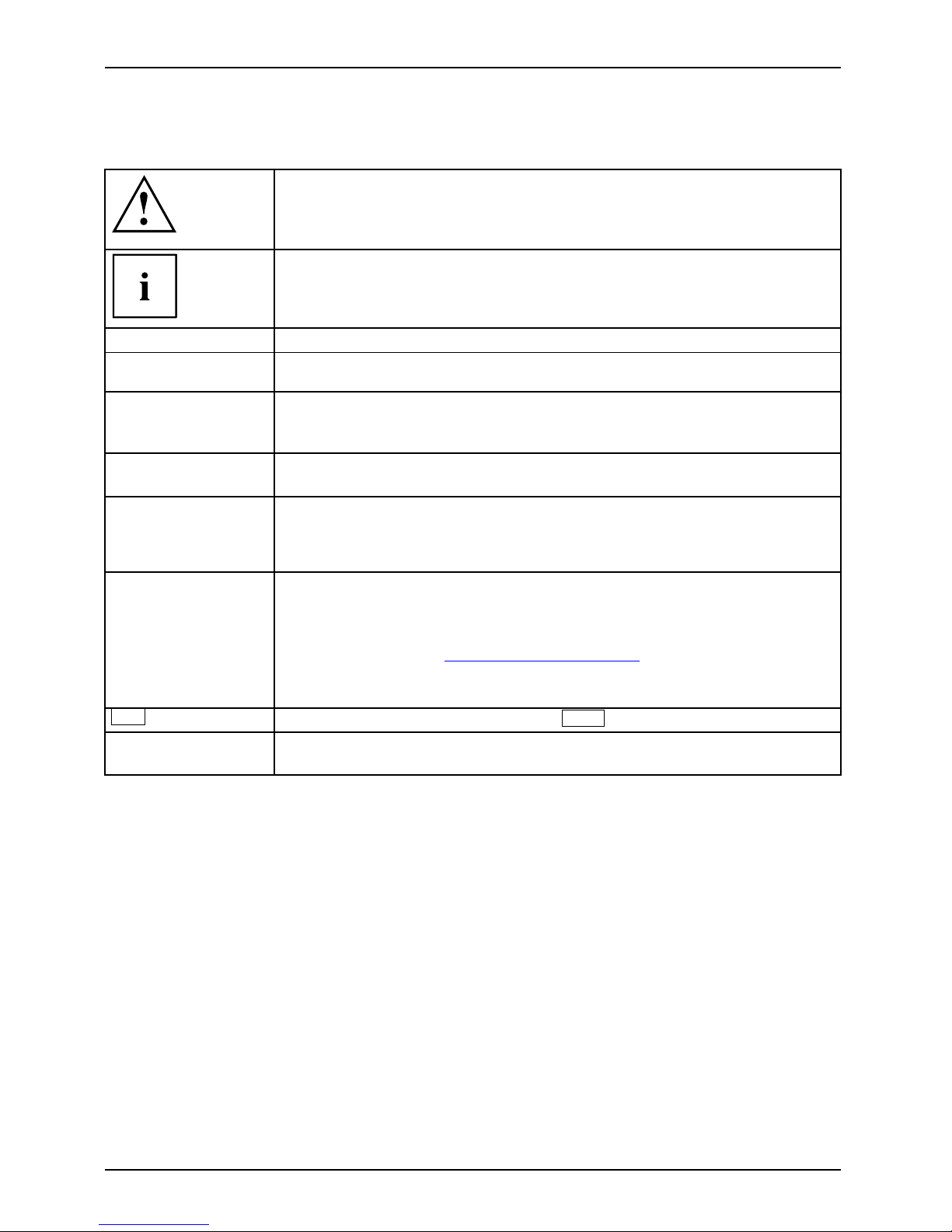
Pay particular attention to text marked with this symbol. Failure to observe
these warnings could pose a risk to health, damage the device or lead
to loss of data. The warranty will be invalidated if the device becomes
defective through failure to observe these warnings.
Indicates important information for the proper use of the device .
►
Indicates an activity t hat must be performed
Indicates a result
This font
indicates data e ntered using the keyboard in a program dialogue or at
the command line, e.g. your password (Name123) or a command used to
start a program (start.exe)
This font
indicates information that is displayed on the screen by a program, e.g.:
Installation is complete.
This font
indicates
• terms and texts used in a software interface, e.g.: Click on Save
• names of program
sorfiles, e.g. Windows or setup.exe.
"This font"
indicates
• cross-refere
nces to another section, e .g. "Safety information"
• cross-references to an external source, e.g. a web address: For more
information, go to "
http://www.fujitsu.com/fts"
• Names of CDs
, DVDs and titles or designations for other materials,
e.g.: "CD/D
VD Drivers & Utilities" or "Safety/Regulations" manual
Key
indicates
a key on the keyboard, e.g:
F10
This font
indicate
s terms a nd texts that are emphasised or highlighted, e.g.: Do
not swit c
h off the device
6 Fujitsu
Page 11
Ports and operating elements
Ports and operating elements
Ports
This chapter presents the individual hardware components of your device. This will provide
you with an overview of the ports and operating elements on the device. Please familiarise
yourself with these components before starting to work with your device.
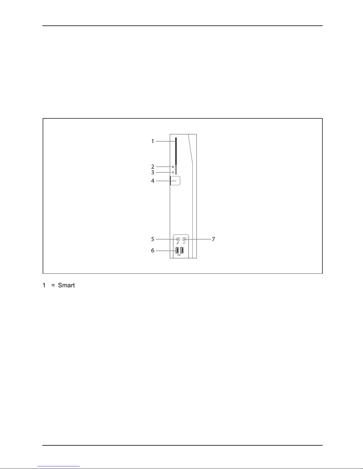
Front view
OnswitchOffswitchPower-onindicatorSmartCardreaderFlashmemoryaccessHeadphoneportAudiooutputMicrophoneportUSB
$
#
"
!
%
1 = SmartCard reader (FUJITSU T hin Client
FUTRO S920 only, optional)
2 = Indicator for SmartCard reader
3 = Flash memory or hard disk access
4 = ON/OFF switch
5 = Microphone jack
6 = USB ports (Universal Serial Bus)
7 = Headphones port, audio output (Line Out)
Fujitsu 7
Page 12

Ports and operating elements
Rear view
LANsocketPS/2mouseportInstallationopeningPS/2keyboardportMonitorportSerialportUSBportsAudiooutputDCinput connectorAudi oinputPCIslotPCIeslotSecurityLoc k
2
3
8
5
7
1
4
6
10
13
12
9
11
14
15
1 = Socket for Power over Ethernet
module (optional)
2 = Audio output (Line Out)
3 = PS/2 keyboard port
4 = USB ports
5 = USB ports
6 = DisplayPort
7 = DVI-I monitor port
8 = DC input jack (DC IN)
9 = Security Lock device
10 = Serial port
11 = Serial port (only for FUJITSU Thin
Client F UT RO S920)
12 = RJ45 socket (Local Are a Network)
13 = PS/2 mouse port
14 = Audio input (Line In)
15 = PCI/PCIe port (FUJITSU Thin Client
FUTRO S920 only, optional)
8 Fujitsu
Page 13

Important notes
Important notes
ImportantnotesNotes
In this chapter you will find information regarding safety w hich it is essential to
take note of when working with your device.
Safety notes
SafetynotesNote
Please follow the safety
notes provided in the "Safety/Regulations" manual
as well as the safety note
s given below.
When installing and ope
rating the device, please observe the notes on amb ient
conditions in "
Technic
al data ", Page 60 and the instructions in "Getting started", Page 15.
Replace the lithium ba
ttery on the mainboard exactly in accordance with the
instructions in the "
R
eplacing the lithium batter y", Page 58 chapter.
Caution, compon ent
s in the system can get very hot.
The activities desc
ribed in these instructions must always be
performed with the
greatest care.
Repairs to the devi
ce must only be carried out by qualified technicians. Incorrect
repairs could put
the user at great risk (electric shock, hazardous energy emissions,
risk of fire)orcau
se serious damage to the equipment.
Operate the devi
ce only with the casing closed.
Power cable and mains adapter:
The supplied p ower cable conforms to the requirements of the country in
which you purchased your device. Make sure that t he power cable is ap proved
for use in the country in which you intend to use it.
The mains adapter’s power cable should only be connected to a mains
socket if the device is connected.
Do not use the mains adapter for oth er devices.
Use only the mains adapter which is intended for use with the device,
see chapter "
Technical data ", Page 60.
Make sure that the rated current of the mains adapter is not higher than that of
the power system to w hich you connect the mains adapte r.
ON/OFF switches do not disconnect the device from the mains voltage. To completely
disconnect the mains voltage, remove the power plug from the power socket.
Fujitsu 9
Page 14

Important notes
Important notes on preparing your FUTRO S720/S920
or ESPRIMO A525-L for use via t
he Power
over Ethernet module
With the aid of the P ower over
Ethernet module, you can operate the FUTRO S720/S920
or the ESPRIMO A525-L over t
he LAN without any additional power c onnection.
You will need a suitable n
etwork infrastructure for this.
To operate the F UTRO S720
/S920 or the ESPRIMO A525-L via the Power over Ethernet module,
midspan devices confor
ming to IEEE 802.3at and shielded CAT 5 network cable or higher quality
cable are required. End
span devices will only be supported in conjunction with a hardware
classification. Fujit
su recommen ds the use of the following midspan devices:
• 1 port midspan from Mic
rosemi PD-9501G: S26361-F1744-L10
• 12 port midspan from Microsemi PD-9512G: S26361-F1 744-L 20
Because of the limit
ed power output, not all hardware configuration levels are possible for
operating the FUTR
O S720/S920 or the ESPRIMO A525-L via the Power over Ethernet
module. The follow
ing hardware configurations are possible:
Internal memory ex
pansion
according to C on figurator
mSATA module (FUTRO) / HDD (ESPRIMO) according to Configurator
SmartCard reade
r
internal SmartC
ard reader
Speaker
internal speake
r
WLAN
internal WLAN module according to Configurator
PCI/PCIe car
ds or extra interfaces
none
Depending on the system utilisation, occupancy of external interfaces (excluding th e keyboard,
screen, microphone and headset) may cause overloading of the Power over Ethernet module.
In order to support the largest p ossible occupancy of interfaces, if an overload occurs the
performance of the system is lowered by a reduction in the CPU frequency. If the CPU frequency
is permanently reduced, the occupancy of the external interfaces must be checked and reduced
accordingly to prevent damage to the Power over Ethernet module or the midspan. Alternatively,
the system can also be connected via a suitable AC adapter (see note in this Operating
Manual). The system must be switched off before the AC adapter is connected.
If you are perhaps retrofitting a FUTRO/ESPRIMO with a Power over Ethernet module,
please pay attention to the maximum possible expansion. If PCI/PCIe expansion cards are
installed (FUTRO S 920), these must be removed, otherwise the P ower over Ethernet module
or the midspan may be overloaded and switched off automa tically.
Important notes on preparing your FUTRO S920
for u se with an external graphics card
The FUTRO S920 may in addition be fitted with a graphics card. Only specially approved
graphics cards are a llowed to be used. If a graphics card is retrofittedintheFUTROS920,itis
important to note that a 65W AC adapter is needed for operation. The FUTRO S920 withou t a
graphics card is only supplied from the factory with a 40W AC adapter as standard.
10 Fujitsu
Page 15
Important notes
Transporting the device
Device,Transp ortationRetransportation
Transport all parts separately in their original packaging or in a packaging which
protects them from kno cks and jolts, to the new site.
Do not unpack them until all transportation manoeuvres are completed.
If the device is broug ht from a cold environment into the room where it will be used,
condensation may occur. Before operating the device, wait until it is absolutely dry
and has reached approximately the same temperature as the installation site.
Cleaning the device
Device,Transp ortationRetransportationSystemunit,seeDevic
e
Turn off all power and equipment switches and disconne ct the power
plug from the mains outlet.
Do not clean any interior parts yourself, leave this job to a service technician.
Do not use any cleaning agents that contain abrasives or may corrode
plastic (alcohol, thinner or acetone).
Never clean the device with water! Water entering into the device could
present a serious risk to users (e.g. electric shock).
Ensure that no liquid enters the system.
Thesurfacecanbe
cleaned with a dry cloth. If particularly dirty, use a cloth that has been
moistened in mil
d domestic detergent and then carefully wrung out.
Use disinfecta
nt wipes to clean the keyboard and the mouse.
Fujitsu 11
Page 16

Important notes
Energy saving, disposal and rec
ycling
DisposalEnergysavingRecyclingDrivers&UtilitiesDVDUserDocumentationDVD
You ca n find information on these subject s in chapter "Activating power-saving mode", Page 25,on
the Recovery DVD or on our website ("
http://www.fujitsu.com/fts/about/fts/environment-care/").
Information on "Ökodesign-Richtlinie":
Regulation 1275/2008, based on the EU Eco-design Directive (2009/125/EU),
defines requirements for the power consumption of electrical a nd electronic domestic
and office devices in stand-by and off mode.
In general, all FUTRO thin client products have been developed for energy-efficient
operation and low stand-by losses. Due to customer-specific and op erating system-specific
requirements, which are the priority for optimal operation, some system settings are
necessary which deviate from the above-mentioned directive.
For administrative purposes, such as remote maintenance of systems, the "Wake-on-Lan" (WoL)
function is indispensable for our customers and is therefore a default s etting. Activation of the WoL
function slightly increases the idle current and the max. permissible power draw in the Off mode can
thus be slightly exceeded. By deactivating the WoL function, it is possible to comply with the legal
requirements. Please see chapter "
Activating power-saving mode", Page 25 for the procedure.
The energy saving mode (ACPI S4 Save-to-disk), which is familiar from many current mobile
and desktop systems, is not available in the embedded operating systems for technical reasons.
Therefore, it is not possible to switch devices with this operating system automatically into Off mode.
The operating system of a thin client is stored on a flash memory with optimised size and is provided
with write protection after configuration has bee n completed by the customer. This prevents data
security from being put at risk through frequent writing to a flash memory, such as when updating
the Swapfiles in the operating system or through other applications. Every flash memory permits
only a limited number of write cycles. Both the activated write prot ection a nd the available, limited
flash memory capacity rule out the possibility of activating energy saving mode (ACPI S4).
12 Fujitsu
Page 17

Important notes
FCC Compliance Statement
If the device complies with the FC C regulations, the FCC sign can be found on the typ e rating plate.
FCCClassBComplianceState
ment
DOC (INDUSTRY CANADA) NOTICES
Notice to Users of Radios and Television:
This class B digital apparatus complies with Can adian ICES-003.
The following statement applies to the products covered in this manual, unless otherwise specified
herein. The statement for other pro ducts will appear in the a ccompan ying documentation.
NOTE:
This equipment has been tested and found to comply with the limits for a "Class B" digital
device, pursuant to Part 15 of the FCC rules and meets all requirements of the Canadian
Interference-Causing Equipment Standard ICES-003 for digital apparatus. These limits are
designed to provide reasonable protection against harmful interference in a residential installation.
This equipment generates, uses and can radiate radio frequency energy and, if not installed
and used in strict accordance with the instructions, may cause harmful interference to radio
communications. How ever, there is no guarantee that interference will not occur in a particular
installation. If this equipment does cause harmful interference to radio or television reception,
which c an be determined by turning the equipment off and on, the user is encouraged to
try to correct the interference by one or more of the following measures:
• Reorient or relocate the receiving antenna.
• Increase the s
eparation between eq uipm ent and the receiver.
• Connect the equipment into an outlet on a circuit different from that to
which the receiver is connected.
• Consult the d
ealer or an experienced radio/TV technician for help.
Fujitsu is not responsible for any radio or television interference caused by unauthorized
modifications of this equipment or the substitution or attachment of connecting cables and
equipment other than those s pecified by Fujitsu. The correction of interferences caused by such
unauthorized modification, substitution or attachment will be the r espo nsibility of the user.
The use of shielded I/O cables is required when connecting this equipment to an y and all optional
peripheral or host devices. Fa ilure to do so may violate FCC and ICES rules.
FCC Radi
ation Exposure Statement
This equipment complies with FCC radiation exposure limits set forth for an uncontrolled environment.
The transmitters in this device must not be co-located or operated in conjunction
with any other antenna or transmitter.
To prevent radio interference to the licensed service, this device is intended to be
operated indoors and away from windows to provide maximum shielding. Equipment (or
its transmit antenna) that is installed outdoors is subject to licensing.
Users are not authorized to modify this produ ct. Any modifications invalidate the warranty.
This equipment may not be modified, altered, or ch anged in any way without signed
written permission from F ujitsu. Unauthorized modification will void the equipment
authorization from the FCC and Industry Canada and the warranty.
Fujitsu 13
Page 18

Important notes
CE marking
This device complies with the requirements of EC directives 2004/108/EC "Electromagnetic
compatibility", 2006/95/EC "Low voltage directive" and 2009/125/EC "Ecod esign directive".
For this purpose, please also note the special information concerning the "Ecodesign directive"
for the FUTRO systems (see "
Energy saving, disposal and recycling", Page 12).
14 Fujitsu
Page 19

Getting started
Getting started
Gettingstarted
Please observe the safety information in the "Important notes", Page 9 chapter.
Settingupthedevice
In order to ensure that the casing is sufficiently ventilated and to prevent overheating,
the device must only be operated with the base foot attached.
If the device is to be built-in, adequate ventilation must be assured.
Fit the base feet for h
orizontal or vertical operation (see "
Vertical operating
position", Page 15 and
"
Horizontal operating position", Page 18).
Vertical operati
ng position
VerticaloperatingpositionOperatingposition,verticalBasefeetSidecover
If you wish to operate the device in the vertical operating position, use
the two feet supplied for vertical operation.
Proceed as follows to prepare the device for the vertical operating position:
► Disconnect the cables if required.
► Lay the device on its top (narrow side) as shown, on a stable, flat and clean surface.
Fujitsu 15
Page 20

Getting started
1
1
1
2
2
► Hook the feet into each of the openings provided for this in the casing (1).
There are lock symbols on the foot, indica ting the direction in which the
foot must be pushe d during installation or removal:
• Secure and lock th e foot = push to the left (closed lock)
• Unlock and release the foot = push to the right (open lock)
► Repeat for each foot: P ush the outer elements of th e foot evenly onto the casing
using both hands, keep the "Push" button pressed (see magnifier) and push the foot
in the direction of the arrow (2) until it is heard to engage.
16 Fujitsu
Page 21

Getting started
► Stand the device on the feet.
► If necessary, reconnect any cables that were previously disconnected.
Fujitsu 17
Page 22

Getting started
Horizontal operating position
If you w ish to operate the device in the horizontal operating position, use
the two feet supplied for horizontal operation.
Proceed as follows to prepare the device for the horizontal operating position:
HorizontaloperatingpositionOperatingposition,horizontalBasefeet
► Disconnect the cables if required.
► Lay the device on its right side as shown, on a stable, flat and clean surface.
1
1
2
2
► Hook the feet into each of the openings provided for this in the casing (1).
There are lock symbols on the foot, indica ting the direction in which the
foot must be pushe d during installation or removal:
• Secure and lock th e foot = push to the left (closed lock)
• Unlock and release the foot = push to the right (open lock)
► Repeat for each foot: Keep the "Push" button pressed down (see magnifier) and push
the foot in the direction of the arrow (2) until it is heard to engage.
18 Fujitsu
Page 23

Getting started
► Stand the device on the feet.
► If necessary, reconnect any cables that were previously disconnected.
Fujitsu 19
Page 24

Getting started
Connecting external devices
Read the documentation on the external device before connecting it.
With the exception of USB devices, always remove all power plugs
before connecting external devices!
Do not connect or disconnect cables during a thunderstorm.
Always take hold of t he act ual plug. Never unplug a cable by pulling the cable itself.
Connect and disco nnect the cables in the order described below.
Connecting the cables
► Turn off all power and equipment switches.
CordCable,
► Remove all power plugs from the grounded mains outlets.
► Connect all the c ables to the device and the external devices. Please make sure that you
always observe the safety notes provided in "
Important notes", Page 9.
► Plug all data communication cables into the appropriate sockets.
► Plug all power cables into the grounded mains outlets.
USB devices are hot-pluggable. This means you can connect and disconnect
USB cables while your device is switched on.
Additional information can be found in "
Connecting external devices to the USB
ports", Page 23 and in the documentation for the USB de vices.
Disconnecting the cables
► Switch off al
l affected devices.
Cable,
► Remove all power plugs from the grounded mains outlets.
► Unplug all d
ata communication cables from the appropriate sockets.
► Disconnect all of the cables from the device and from the external devices.
20 Fujitsu
Page 25

Getting started
Ports on the device
PortsExternaldevicesDevice
The ports are located on the front and rear side of the device. The ports available on
your device depend on the configuration level you have selected. The standard ports are
marked with the symbols shown below (or similar). Detailed information on the location
of the ports is provided in the manual for the mainboard.
Headphones, black (front of
device)
Headphones
Microphone port, black (front of device)
Microphoneport
Audio output (Line Out), light
green
AudiooutputLineout
Audio input (Line In), light blue
AudioinputLinein
Serial port, turquoise
Serialport
DVI-I monitor port, white
Monitorport
USB - U niversal Serial Bus:
• blue: USB 3 .0, front of
device
• black: USB 2.0, rear of
device
UniversalSerialBus
RJ45-LAN port
LANport
PS/2 mouse port, green
MouseportPS/2mouseport
PS/2 keyboard port, purple
Keyboardport
DP DisplayPort
DisplayPort
Some of the connected devices require special software (e.g. drivers) (refer to the
documentation for the connected device and operating system).
Connecting a monitor
► Follow the instructions contained in the monitor manual to prepare the monitor
for operation (e.g . connecting cables).
Monitor,
► Connect the data cable to the req uired monitor port on your device.
► Plug the monitor power cable into the grounded mains outlet.
Fujitsu 21
Page 26

Getting started
Connecting the mouse
You can connect a USB mouse or a PS/2 mouse to your device.
Mouse,Connecting,
Connecting a USB mouse
► Connect the USB mouse to one o f the USB ports on the device.
USBport,USBport
Connecting a PS/2 mouse
The PS/2 mouse is only detected by the device if you connect the mouse when
the device is switched off and then switch the device on again.
► Switch your device off.
If you do not attach a m ouse to the PS/2 mouse port, you can disable the mouse
controller in the BIOS Setup in order to free the IRQ12 for a different application.
► Connect th e PS/2 mou
se to the PS/2 mouse port of the device.
PS/2mouse,Con nect ing,PS/2mouse,
► Switch your device on again.
Connecting the keyboard
You can connect a USB keyboard or a PS/2 keyboard to your device .
Keyboard,Connecting,
Connecting a USB keyboard
Use the supplied keyboard cable only.
USBport,Connecting,
► Plug the rectangular connector of the keyboard cable into the rectangular socket
on the underside or on the rear of the keyboa rd.
► Insert the flat rectangular USB plug of the keyboard cable into one of the device’s USB ports.
USBport
Connecting a PS/2 keyboard
Use the supplied keyboard cable only.
Connect
ingaPS/2keyboard
Connect
ing,
The PS/2 keyboard is only detected by the device if you connect the keyboard
when the device is switched off an d then switch the device on again.
► Switch yo
ur device off.
► Plug the rectangular connector of the keyboard cable into the rectangular socket
on the underside or on the rear of the keyboa rd.
► Plug th
e round plug of the keyboard cable into the keyboard po rt on the device.
Keyboard,
► Switch your device on again.
22 Fujitsu
Page 27

Getting started
Connecting external devices to the serial interface
SerialinterfaceSerialinterface,Externaldevices,Devices,
External devices can be connected to the serial interface (e.g. a printer or modem).
► Connect the data cable to the external device.
► Connect the data cab le to the corresponding serial interface.
For an exact description of how to connect external devices to the corresponding
port, please see the external device documentation.
Port settings
Serialinterface,
You can change the port settings (e.g. address, interrupt) in the BIOS Setup.
Device drivers
Devicedrivers,
The devices connected to the serial interface require d rivers. Your operating syste m
already includes many drivers. If the required drive is missing, install it. The latest
drivers are usually available on the Internet or will be supplied on a data carrier.
Connecting external devices to the USB ports
USBdevices,USBport,Externaldevices,Devices,
You can connect a wide range of external d evices to the USB ports (e.g.
printer, scanner, modem or keyboard).
USB devices a re hot-pluggable. This means you can connect and disconnect
USB cables while your device is switched on.
Additional information can be found in the documentation for the USB devices.
► Connect the data cable to the external device.
► Connect th e d
ata cable to one of the USB ports on your device.
Device drivers
The extern
al USB devices you connect to the USB ports usually require no driver of their
own, as the
required software is alrea dy included in the operating system. If the device
requires
separate software, please note the information in the manufacturer’s manual.
To ensure
the transmission capacity of USB 2.0, the cable from the external USB device
to the US
B port of y our device must not be longer than 3 m / 118.11 inches.
Fujitsu 23
Page 28

Getting started
Connecting microphone, headphones, line-out
and line-in dev ice s
MicrophoneHeadphonesLine- out devices
► Connect the microphone to the microphone port.
► Connect the headphones to the
headphones port.
► Connect line-out devices to the audio output.
► Connect the external line
-in devices to the audio input.
Connecting the mains adapter
Mainsadapter
► Connect the mains adapter cable to the device.
► Connect the power cable to the mains adapter.
► Plug the power cable into a grounded mains outlet.
Connecting the devi
ce to the network (LAN)
LAN
► Connect the 10/100/1000 Base T network cable to the RJ45 LAN port.
24 Fujitsu
Page 29

Operation
Operation
Switch the device on
► If necessary, switch the monitor on (see the operating manual for the monitor).
Device,Monitor,
► Press the ON/OFF switch on t
he front of the device.
The pow er indicator lights up and the device starts.
Switching off the device
► Shut down the operatin
g system in the proper way. In Windows: from the
Start menu select the
Shut Down option.
Device,Monitor,
► If th e operating system does not automa tically switch the device into energy-saving mode or
switch it off, press the ON/OFF switch. Warning, this could lead to a loss of data!
Ifthedeviceisswi
tched off, it consumes a minimum of energy.
The ON/OFF switch
does not disconnect the device from the m ains voltage. To
completely disco
nnect the mains voltage, remove the power plug from the power socket.
► If necessary, switch the monitor off (see the operating man ual for t he monitor).
Activating power-saving mode
Duetocustom
er requirements and requirements of the operating system, the "Wake-on-LAN"
(WoL) functi
on is set by default. The WoL function increases the idle current slightly.
In order to m
eet the requirements of EU Directive “COMMISSIO N REGULATION
(EC) No 1275
/2008 of 17 December 2008 implementing Directive 2005/32/EC”, the
default Wo
L setting must be changed as follows:
► To st a rt t
he B IOS Setup Utility after system boot, press function key
F2
.
► In the Power sub-menu, select the Low Power Soft O ff setting and switch it to enabled.
► To save th
e setting and exit the BIOS Setup Utility, press function key
F4
.
After making this change, the system will a chieve the lowest energy
saving mode during shut-down.
Open BIOS Setup
BIOS-Setup
► When t
he syst em starts, press the
F2
key (several times if necessary).
BIOS Setup will be started. Select one of t he tabs to access other setting options in BIO S Setup .
PXE system boot
PXE
systemboot
► Swi
tchthedeviceonwiththeON/OFFswitch.
Fujitsu 25
Page 30

Operation
► When starting the system, press the
F12
key several times.
The boot menu is displayed.
► Select the desired boot option.
Calling the PXE system boot co
nfiguration menu
► Press the key combination
↑
+
F10
while Realtek RTL8139(X)/8130/810X Boot Agent is
displayed.
The following or a simila
r display appears on the screen:
Configuration menu screen.
The following settings are possible:
Network B oot
Protocol:
PXE (standard)
or RPL
Specification of the system boot protocol used.
Boot Order: Int 19h
The network is always started first before the local
devices are activated.
PnP/ BEV (BBS)
If a BBS-BIOS (BIOS Boot Specification) exists,
the system is started by the BBS-BIOS.
ROM Disabled
The entire mechanism for the system boot is
deactivated. The system can only be activated via
the local devices.
Int 18h
The devices set in BIOS Setup are enabled.
26 Fujitsu
Page 31

Operation
Show Config
Message:
The following message can be activated or deactivated during the
system boot:
Realtek RTL8139(X)/8130/810X Boot Agent Press Shift-F10
to configure …….
Show
Message
Time:
Indicates the time in second
s for which the following m essa ge is
displayed during the system
boot:
Realtek RTL8139(X)/8130
/810X Boot Agent Press Shift-F10
to configure …….
The settings are not effective until after s aving and another PXE system boot.
Fujitsu 27
Page 32

System expansions
System expansions
Upgrades,Device,System expansionComponentsServicing
Repairs to the device must only be performed by qualified technicians. Incorrect repairs
may greatly endanger the user (electric shock, fire risk) and will invalidate your warranty.
After consulting the Hotline/Help Desk, you may remove and install the components
described in this manual yourself.
As the device has to be shut down in order to install/deinstall system hardware
components, it is a good idea to print out the relevant sections of this chapter beforehand.
The following illustrations may differ slightly from your device, depending on its configuration level.
If further documentation was delivered with your device, please also read this through carefully.
In addition, before removing or installing system components, please pay attention to the following:
The device must be switched off when installing/removing the system
expansions and may not be in energy-saving mode.
Remove the power plug before opening the device.
Be careful that no wires become trapped when removing or installing components.
When installing components that become very hot, make sure that the maximum
permissible temperature of the components in operation is not exceeded.
An update of the BIO S may be required for a system expansion or hardware
upgrade. Further information can be found in the BIOS help section or if
necessary in the Technical Manual for the mainboard.
Overview o
f optional system components
The following optional system components can be installed in the various device types:
System component
FUJITSU Thin Client
FUTRO S720
FUJITSU Thin Client
FUTRO S920
FUJITSU Desktop
ESPRIMO A525-L
Hard disk
——
Installed when
delivered
SmartC
ard reader
optional optional
—
Speaker
optio
nal
optio
nal
optio
nal
PoweroverEthernet
module
optional optional optional
Third serial port
—
optional*
—
Parallel port
—
opt
ional*
—
PCIe dual serial card
—
optional*
—
PCIe ATI V3900
—
optional*
—
28 Fujitsu
Page 33

System expansions
* In each case, only one of these components can be simultaneously installed in a system.
Possible combinations for the
FUJITSU Thin
Client FUTRO S920
For the FUJITSU Thin Client FUTRO S920, th e following system components can be combined
together:
System
component
Smart
Card
reader
Speaker
Power
over
Ethernet
module
Third
serial
port
Parallel
port
PCIe dual
serial
card
PCIe ATI
V3900
Smart
Card
reader
—
Speaker
—
Power
over
Ethernet
module
—————
Third
serial
port
—————
Parallel
port
—————
PCIe dual
serial card
—————
PCIe ATI
V3900
—————
Fujitsu 29
Page 34

System expansions
Information about boards
Take care with the locking mechanisms (ca tche s and centring pins) when you
are replacing boards or components on boards.
Note that some components on the mainboard may be very hot if the device was
in use shortly before the casing was removed.
To preven t d amage to the board or the components and co nductors on it, please take care when
you insert or remove boards. Make sure expansion boards are inserted straightly.
Never use sharp objects (screwdrivers) for leverage.
Boards with electrostat
ic sensitive devices (ESD) are identifiable by the label
shown.
When handling boards fit
ted with ESDs, you must always observe the
following points:
• You must always disc
harge static build up (e.g. by touching a grounded
object) before work
ing.
• The equipment and tools you use must be free of static charges.
• Only touch or hold t
he boards by the edge or, if present, at the areas
marked green (Touc
h Points).
• Never touch pins or conductors on boards fitted with ESDs.
30 Fujitsu
Page 35

System expansions
Opening the casing
Casing,Device,
► Switch the device off. The device must not be in power-saving mode.
Please observe the safety information in "Important notes", Page 9.
Disconnect the mains plug from the mains outlet.
Only insert the power plug after you have closed the casing.
Open the casing carefully because there are WLAN cables that lead from the casing
cover to the system and these may break if the casing is opened carelessly.
► Remove any connected wi
res which are in the way.
2
2
3
1
1
► Loosen the screws at the rear (1).
► Slide the casing cover in the direction of the arrow (2) and swing out the
casing cover towards the front (3).
Fujitsu 31
Page 36

System expansions
Adding memory
MemorymoduleMainmemoryRemovingmemorySystem expansionSystemexpansion
If you want to remove or add memory, proceed as follows:
Please observe the safety information in chapter "Important notes", Page 9.
Only use memory expansions for notebooks: 1 GByte and 2 GByte modules
DDR3-1333 SO DIMM or D DR3-1600 SO DIMM.
Never use force when installing or removing a mem ory extension.
Make sure that foreign objects do not fall into the memory extension compartment.
Individual components (e.g. the processor heat sink) can become very hot
during operation. We therefore recommend that you wait one hour after
switching off the device before removing or installing the memory modules.
Otherwise, there is a risk of suffering burns!
As some components are exposed that are sensitive to static electricity, please
take note of chapter "
Information about boards", Page 30.
Removing memory mod
ules
3
2
1
1
► Carefully push the two mounting
clips outwards (1).
MemoryexpansionMemorymodule
The memory module s
naps upwards (2).
► Pull the memory module ou t of its slot
in the direction of the a rrow (3 ).
Installing a memory module
2
a
1
► Insert the memory module with the contacts
and the recess (a) facing the slot (1).
Memorye
xpansion
Memorym
odule
► Carefully push the memory module
downwards until you feel it click
into place (2).
32 Fujitsu
Page 37

System expansions
Installing and removing the SmartCard reader
(FUJITSU Thin Client FUTRO S9
20 only)
If you are also installing the optional loudspeaker, install the SmartCard
reader before the loudspeaker.
Installing the SmartCard reader
SmartCardreader
If not already installed, you can fit a SmartCard reader.
► Open the casing (see "
Opening the casing", Page 3 1).
► If a PCIe board is installed, you must remove the cross piece and PCIe
board (see "
Removing the board", Page 57).
1
► Careful
ly remove the cover of the SmartCard reader bay from the casing cover (1).
Fujitsu 33
Page 38

System expansions
1
2
► Place the carrier for th e SmartCard reader in the casing (1).
► Fasten the carrier with the screw (2).
34 Fujitsu
Page 39

System expansions
3
2
2
1
4
► Place the SmartCard reader on the c arrier with the component side facing
downwards, in the direction of the arrow ( 1).
► Fasten the SmartCard reader onto the carrier with the screws (2).
► Connect the cable to the SmartCard reader (3) and to the connector on th e mainboard (4).
► When required, reinstall the cross piece and the PC Ie board (see "
Installing the board", Page 55).
► Clo se the casing (see "
Closing the casing", Page 59).
Make sure that the c ables are not trapped between the casing and the components.
Fujitsu 35
Page 40

System expansions
Removing the SmartCard re ader
SmartCardreader
► Open the casing (see "Opening the casing", Page 31).
► If a PCIe board is installed, you must remove the cross p iece and PCIe
board (see "
Removing the board", Page 57).
1
3
3
4
2
► Disconnect the cable from the SmartCard reader (1) and from the mainboard (2).
► Undo the screw s (3).
► Lift the SmartCard reader from the carrier (4).
► When required, reinstall the cross piece and the PCIe board (see "
Installing the board", Page 55).
► Close the casing (see "
Closing the casing", Page 59).
Ensure that cables are not trapped between the casing and the components.
36 Fujitsu
Page 41

System expansions
Information about installing and removing
a speaker (optional)
You can install an additional speaker in your device:
• For FUJITSU Thin Client FUTRO S720 / FUJITSU Thin Client FUTRO S920, see
chapter "
Installing and removing a speaker: FUJITSU Thin Client FUTRO S720
/ FUJITSU Thin Clien t FUTRO S920", Page 37
• For FUJITSU Desktop ESPRIMO A525-L, see chapter "Installing and removing a
speaker: FUJITSU Desktop ESPRIMO A525-L", Page 41
Installing and removi
ng a speaker: FUJITSU Thin
Client FUTRO S720 / FUJITSU Thin Client FUTRO S920
Installing the loudspeaker
Loudspeaker
The required hexagon head bolts are included in the delivery scope of the loudspeaker.
► Open the housing (see "
Opening the c asing", Page 31).
► If a P CIe board i
s installed, you must remove the cross piece and PCIe
board (see "
Re
moving the board", Page 57).
Fujitsu 37
Page 42

System expansions
4
1
1
► Secure the h exagon head bolts provided into the screw holes (1).
38 Fujitsu
Page 43

System expansions
2
1
1
► Insert the loudspeaker into the housing as illustrated.
► Secure the loudspeaker with the screws (1).
► Connect the loudspeaker cable to the connector on the mainboard (2).
► When required, reinstall the cross piece and the PC Ie board (see "
Installing the board", Page 55).
► Close the housing (see "
Closing the casing", Page 59).
Ensure that the cables are not trapped between the hou sing and the components.
Fujitsu 39
Page 44

System expansions
Removing the loudspeaker
Loudspeaker
► Open the housing (see "Opening the casing", Page 3 1).
► If a PCIe board is installed, you must remove the cross p iece and PCIe
board (see "
Removing the board", Page 57).
1
2
2
► Disconnect the loudspeaker cable from the mainboard (1).
► Undo the screw s (2).
► Lift the loudspeaker out of the housing.
► When required, reinstall the cross piece and the PCIe board (see "
Installing the board", Page 55).
► Close the housing (see "
Closing the casing", Page 59).
40 Fujitsu
Page 45

System expansions
Installing and removing a speaker: FUJITSU
Desktop ESPRIMO A525-L
Before installing a speaker in the FUJITSU Thin Client ESPRIMO
A525-L, you must first remove the hard disk.
Installing a speaker
Removing a hard disk
Harddisk
► Open the housing (see "Opening the casing", Page 31).
1
1
2
► Disconnect the cables from the hard disk (1).
► Undo th e s crew (2).
Fujitsu 41
Page 46

System expansions
1
2
2
► Slide the hard disk in the direction of the arrow (1).
► Lift the hard disk out of the casing (2).
42 Fujitsu
Page 47

System expansions
Installing the loudspeaker
Loudspeaker
The required hexagon head bolts are included in the delivery scope of the loudspeaker.
4
1
1
► Secure the
hexagon head bolts provided into the screw holes (1).
Fujitsu 43
Page 48

System expansions
2
1
1
► Insert the loudspeaker into the housing as illustrated.
► Secure the loudspeaker with the screws (1 ).
► Connect the loudspeaker cable to the connector on the mainboard (2).
44 Fujitsu
Page 49

System expansions
Installing a hard disk
Loudspeaker
2
1
2
► Insert the hard disk into the casing (1).
► Slide the hard disk in the direction of the arrow (2).
Fujitsu 45
Page 50

System expansions
2
2
1
► Secure the hard disk with the screw (1).
► Connect the cables to the hard disk (2).
► Close the housing (see "
Closing the casing", Page 59).
Make sure that the cables are not trapped between the casing and the components.
46 Fujitsu
Page 51

System expansions
Removing a speaker
Removing a hard disk
Harddisk
► Open the housing (see "Opening the casing", Page 31).
1
1
2
► Disconnect the cables from the hard disk (1).
► Undo th e s crew (2).
Fujitsu 47
Page 52

System expansions
1
2
2
► Slide the hard disk in the direction of the arrow (1).
► Lift the hard disk out of the casing (2).
48 Fujitsu
Page 53

System expansions
Removing the loudspeaker
Loudspeaker
1
2
2
► Disconnect the loudspeaker cable from the mainboard (1).
► Undo the s crews (2).
► Lift the loudspeaker out of the housing.
Fujitsu 49
Page 54

System expansions
Installing a hard disk
Loudspeaker
2
1
2
► Insert the hard disk into the casing (1).
► Slide the hard disk in the direction of the arrow (2).
50 Fujitsu
Page 55

System expansions
2
2
1
► Secure the hard disk with the screw (1).
► Connect the cables to the hard disk (2).
► Close the housing (see "
Closing the casing", Page 59).
Make sure that the c ables are not trapped between the casing and the components.
Installing and removing a Power over Ethernet
module (optional)
You can install an ad ditional Power over Ethernet module in your device.
Before using the module for the first time, please pay attention to the notes in
chapter "
Important notes on preparing your FUTRO S720/S920 or ESPRIMO A525-L
for use via the Power over Ethernet module", Page 10.
If you are supplying the system with power via the PoE m odule, ensure that
no additional power supply (mains adapter) is connected.
Fujitsu 51
Page 56

System expansions
Installing the Power over Ethernet module
PoweroverEthernetmodule,
► Open the casing (see "Opening the casing", Page 31).
► If a PCIe board is installed, you must remove the cross p iece and PCIe
board (see "
Removing the board", Page 57).
► FUJITSU D esktop ESPRIMO A525-L: If a hard disk is installed, remove
it (see "
Removing a hard disk", Page 41).
1
2
► Break the cover (1) out of the casing.
► Place the Power over Eth ernet module in the casing with the comp onent side
facing upwards (2). Ensure that it engages in the slot.
52 Fujitsu
Page 57

System expansions
1
1
► Secure the Power over Ethernet module with the screws (1).
► FUJITSU Desktop ESPRIMO A525-L: When required, reinstall the hard disk
(see "
Installing a hard disk", Page 45).
► When required, reinstall the cross piece and the PC Ie board (see "
Installing the board", Page 55).
► Clo se the casing (see "
Closing the casing", Page 59).
Make sure that the c ables are not trapped between the casing and the components.
Fujitsu 53
Page 58

System expansions
Removing the Power over Ethernet module
PoweroverEthernetmodule,
► Open the casing (see "Opening the casing", Page 31).
► If a PCIe board is installed, you must remove the cross p iece and PCIe
board (see "
Removing the board", Page 57).
► FUJITSU D esktop ESPRIMO A525-L: If a hard disk is installed, remove
it (see "
Removing a hard disk", Page 41).
1
2
1
► Undo the screw s (1).
► Pull the Power over Ethernet module in the direction of the arrow (2) out
of the slot and lift it out of the casing.
► FUJITSU Desktop ESPRIMO A525-L: When required, reinstall the hard disk
(see "
Installing a hard disk", Page 45).
► When required, reinstall the cross piece and the PCIe board (see "
Installing the board", Page 55).
► Close the casing (see "
Closing the casing", Page 59).
Ensure that cables are not trapped between the casing and the components.
54 Fujitsu
Page 59

System expansions
Installing a nd removing a board
You can install various boards (e.g. a graphics card) in your device.
Before using a graphics card for the first time, please pay attention to
the notes in chapter "
Important notes on preparing your FUTRO S920 for
use with an external graphics card", Page 10.
The installation and removal procedure is the same for all types of
board. A PCIe board is shown below.
Installing the board
Board,
You can only install boards with a maximum length of 170 mm.
► Enter the required settings for the board.
► Open the casing (see "
O
pening the casing", Page 31).
2
1
► Inser
t the riser card in its slot (1).
► Undo the screw (1) and remove the rear slot cover plate of the slot (2 ).
Fujitsu 55
Page 60

System expansions
Do not throw away the rear slot cover plate. For cooling, protection
against fire and in order to comply with EMC regulations, you must refit
the cover plate if you remove the board.
4
2
3
1
► Insert the board into the riser card (1).
► Fix the board with the screw (2).
► Install the cross piece (3).
► Secure the cross piece with the screw (4).
► Close the casing (see "
Closing the casing", Page 59).
56 Fujitsu
Page 61

System expansions
Removing the board
Board,
► Open the casing (see "Opening the casing", Page 31).
1
2
► Loosen the screw (1).
► Remov e the board from the riser card (2).
You must reinstall the rear slot cover plate due to cooling, fire protection and the EM C
regulations (regulations on electromagnetic compatibility) to be complied with.
► Reinstall the rear slot cover plate by inserting it in the installation slot from
the inside and securing it with the screw.
► Clo se the casing (see "
Closing the casing", Page 59).
Fujitsu 57
Page 62

System expansions
Replacing the lithium battery
In order to permanently save the system information, a lithium battery is installed to provide
the CMOS-memory with a current. A corresponding error message notifies the user when the
charge is too low or the battery is empty. The lithium battery must then be replaced.
Incorrect replacement of the lithium battery may lead to a risk of explosion!
The lithium battery may be replaced only with an identical battery or with
a type recommended by the manufacturer.
Do not dispose of lithium batteries with household waste. They must be disposed
of in accordance with local regulations concerning special waste.
Make sure that you observe the correct polarity when replacing the lithium
battery. The plus pole must be on the top!
Lithiumbattery,Replacing,Replacing,Replacing,lithiumbatteryBattery
The lithium battery holder exists in different designs that function in the same way.
1
2
3
1
2
3
► Press t
he catch in the direction of the arrow (1).
The battery jumps out of the holder slightly.
► Remov
e the battery (2).
► Push the new lithium battery of the identical type into the holder (3) an d
press it down until it engages.
58 Fujitsu
Page 63

System expansions
Closing the casing
CasingCasing cover
► Replace the casing cover on the device and push it backwards.
► Secure the casing cover with the two screws on the rear of the device.
Make sure that the c ables are not trapped between the casing and the components.
► Connect all the cables removed before.
Fujitsu 59
Page 64

Technical data
Technical data
Technicaldata
FUTRO/ESPRIMO
Electrical data
FUTRO S720 FUTRO S920 ESPRIMO A525-L
Processor:
AMD eKabini 1.65 GHz
Dual Core
AMD eKabini 1.5 GHz
Quad Core
AMD eKabini 1.65 GHz
Dual Core
Rated voltage: 19 - 20 V
Max. rated
current:
2.0 A or 3.25 A 2.0 A or 3 .25 A 2 A
Dimensions (vertical operating position)
Width x D epth
x Height (with
foot):
97 mm x 195 mm x 267 mm / 3.82 inches x 7.68 inches x 10.51 inches
WidthxDepthx
Height (without
foot):
52 mm x 195 mm x 250 mm / 2.05 inches x 7.68 inches x 9.84 inches
Dimensions (horizontal operating position, without WLAN)
Width x D epth
x Height (with
foot):
295 mm x 195 mm x 72 mm / 11.61 inches x 7.68 inches x 2.63 inches
WidthxDepthx
Height (without
foot):
250 mm x 1 95 mm x 57 mm / 9.84 inches x 7.68 inches x 2.05 inches
Weight
in basic
configuration:
approx. 1 .2 kg / 2.64 lbs approx. 1.3 kg / 2.87 lbs approx. 1.4 kg / 3.08 lbs
Environmental conditions
Temperature:
• Operation
• Transpor-
tation
15 °C .... 35 °C / 59 °F ... 95 °F
–25 °C .... 60 °C / –13 °F ... 140 °F
Clea
rance
requ
ired to
ensu
re adequate
ven
tilation:
Mini
mum of 200 mm / 7.87 inches on all sides
Condensation must be avoided during ope ration.
60 Fujitsu
Page 65

Technical data
AC adapter
Electrical data
Rated voltage: 100 - 240 V
Max. rated current:
1.2A(40W)or1.5A(65W)
Rated frequency:
50 - 60 Hz
Only the following adapters with Limited Power Source may be used:
• 40W: S26113-E578-V55-01 Model: ADP-40PH AD
• 65W: S26113-E557-V55-03 Model: ADP-65JH AD
Fujitsu 61
Page 66

Index
Index
A
Audio input 21
line in 8
Audio output 21
line out 7
Line Out 8
B
Base feet 15, 18
Battery 58
BIOS-Setup
opening 25
Board,
installing 55
removing 57
C
Cable,
connecting 20
disconnecting 20
Casing
closing 59
Casing cover 59
Casing,
opening 31
Components
installing/removing 28
Connecting a PS/2 keyboard 22
Connecting,
keyboard 22
mouse 22
PS/2 keyboard 22
PS/2 mouse 22
USB keyboard 22
Cord
see Cable 20
D
DC input connector
DC IN 8
Device
Ports 21
Device drivers,
serial interface 23
Device,
opening 31
switching off 25
switching on 25
transporting 11
upgrades 28
Devices,
connecting 23
DisplayPort 21
Disposal 12
Drivers & Utilities DVD 12
E
Energy saving 12
External devices
Ports 21
External devices,
connecting 23
F
Flash memory a ccess 7
G
Getting started 15
H
Hard disk
removing 41, 47
Headphone port 7
Headphones 21
connecting 24
Horizontal operating position 18
I
Important notes 9
Installation opening
for m o dules 8
K
Keyboard port 21
Keyboard,
connecting 22
port 22
L
LAN 24
LAN port 21
LAN socket 8
Line in 21
Line out 21
Line-out devices
connecting 24
62 Fujitsu
Page 67

Index
Lithium battery,
replacing 58
Loudspeaker
installing 37, 43
removing 40, 45, 49–50
M
Main memory
see A dding memory 32
Mains adapter
connecting 24
Memory expansion
installing 32
removing 32
Memory module
important notes 32
installing 32
removing 32
Microphone
connecting 24
Microphone port 7, 21
Monitor port 8, 21
Monitor,
Connecting 21
switching off 25
switching on 2 5
Mouse port 21
Mouse,
connecting 22
N
Note
safety 9
Notes
important 9
O
Off s witch 7
On switch 7
Operating position, horizontal 18
Operating position, vertical 15
P
PCI slot 8
PCIe slot 8
Ports 7, 21
Power over Ethernet module,
installing 52
removing 54
Power-on indicator 7
PS/2 keyboard port 8
PS/2 mouse port 8, 21
PS/2 mouse,
connecting 22
port 22
PXE system boot 25
R
Recycling 12
Removing memory
see Adding memory 32
Replacing,
lithium battery 58
Replacing, lithium battery 58
Retransportation 11
S
Safety notes 9
Security Lock
Security Lock device 8
Serial interface 23
Serial interface,
connecting devices 23
settings 23
Serial port 8, 21
Servicing 28
Side cover 15
SmartCard reader
indicator 7
installing 33
removing 36
System expansion 28, 32
see Adding memory 32
System unit, see Device 11
T
Technical data 60
Transportation 11
U
Universal Serial Bus 21
Upgrades,
device 28
USB
ports 7
USB devices,
connecting 23
USB port 22
USB port,
connecting devices 23
connecting keyboard 22
connecting the mouse 22
Fujitsu 63
Page 68

Index
USB ports 8
User Documentation DVD 12
V
Vertical operating position 15
64 Fujitsu
 Loading...