

Page 1

Operating Manual
ESPRIMO E352x / E372x / E4xx
System
Page 2

Congratulations, you have
innovative Fujitsu product.
decided to buy an
The latest information about our products, useful tips, updates etc. is available
on our website: "
For automatic driver updates, go to:"http://support.ts.fujitsu. com/com/support/index.html"
Should you have any technical questions, please contact:
• our Hotline/Service Desk (see the Service Desk list or visit:
"
http://ts.fujitsu.com/support/servicedesk.html")
• Your sales partner
• Your sales office
We ho pe you really enjoy using your new Fujitsu system.
http://ts.fujitsu.com"
Page 3

Page 4

Copyright
Fujitsu Tec
Published by
Fujitsu Technology Solutions GmbH
Mies-van80807 Munich, Germany
Contact
h
All rights reserved, including intellectual property rights. Technical data subject to modifications and delivery subject to
availability. An y liability that the data and illustrations are complete, actual or correct is excluded. Desig nations may be
tradem
infringe the rights of such owner. You will find more information at "
Order N
hnology Solutions 09/11
der-Rohe-Straße 8
s.fujitsu.com/support
ttp://t
arks and/or copyrights of the respective manufacturer, the use of which by third parties for their own purposes may
http://ts.fujitsu.com/term s_of_use.html"
o. Fujitsu Technology Solutions GmbH: A26361-K1180-Z220-1-7619, edition 4
Page 5

ESPRIMO E352x / E372x / E4xx
Operating Manual
Your ESPRIMO 5
Important notes 7
Ports and operating elements 10
Getting started 12
Operation 21
Problem solutions and tips 26
System expansions 31
Technical specification 53
Index 54
Page 6

ESPRIMO is a registered trademark of Fujitsu Technology Solutions GmbH.
Windows 7, Windows Vista and Windows XP are registered trademarks of Microsoft Corporation.
PS/2 is a registered trademark of International Business Machines, Inc.
Pentium is a registered trademark of Intel Corporation, USA.
Kensington and MicroSaver are registered trademarks of ACCO World Corporation.
All other trademarks referenced are trademarks or registered trademarks of their
respective owners, whose protected rights are acknowledged.
Copyright © Fujitsu Technology Solutions Gm bH 2011
All r ights reserved, including rights of translation, reprodu ction by printing, copying
or similar methods, either in part or in whole.
Noncompliance is subject to compensation for damages.
All rights reserved, including rights created by patent grant or registration of a utility model or design.
Subject to availability and technical modifications.
Page 7

Contents
Contents
YourESPRIMO ......................................................................... 5
Notational co nventions .................................................................. 6
Important notes ........................................................................ 7
Safety information ....................................................................... 7
Transporting the device
Cleaningthe device ..................................................................... 8
Energy saving, disposa
CE marking ............................................................................ 8
FCC Compliance Statem
FCC Class B Compliance
Ports and operatingelements ......................................................... 10
Front ................................................................................... 10
Rear ................................................................................... 11
Getting started ......................................................................... 12
Unpacking and che
Steps for initial
Setting up the dev
Vertical operat
Connecting the d
Connecting ext
Connecting th
Disconnectin
Ports on the de
Connecting a
Connecting t
Connecting t
Connecting
Connecting
Switching
Switching
Installi
Operation .............................................................................. 21
Switch the device on .................................................................... 21
Switching off thedevice ................................................................. 21
Indicators onthe device ................................................................. 21
Keyboard ............................................................................... 23
Important keys and keyboard shortcuts . . . . ............................................ 24
Settingsin BIOS Setup .................................................................. 25
Property and data protection . . ........................................................... 25
Anti-theft protection and lead-sealing . . . . . . ............................................ 25
lem solutionsand tips ............................................................
Prob
if problems occur ...................................................................
Help
bleshooting .........................................................................
Trou
Pow
The
Mon
No
setup ....................................................................
ernal devices .............................................................
externaldevices tothe serial interface .....................................
externaldevices tothe USB ports .........................................
on for the first time:installing the software .......................................
on monitorand device .....................................................
ng thesoftware ...............................................................
er indicatorremains off after you have switched onyour device .....................
device cannot be switched off with the ON/OFF switch .............................
itorremains blank ...............................................................
mousepointer displayed on the screen ............................................
..................................................................
land recycling ....................................................
ent .............................................................
Statement ..................................................
cking thedelivery .....................................................
ice ....................................................................
ing position (optional) . . . . . . ............................................
evice to the mains supply ................................................
ecables ...............................................................
gthe cables ............................................................
vice ..................................................................
monitor ................................................................
he mouse ...............................................................
he keyboard . ...........................................................
12
12
13
13
15
16
16
16
17
17
18
18
18
19
19
20
20
26
26
26
26
27
27
29
7
8
9
9
Fujitsu Technology Solutions 3
Page 8

Contents
Time and/or date is not correct . . . . . . ................................................. 29
Error messages on the screen ........................................................ 29
Installing new software .................................................................. 29
Restoring thehard disk contents ......................................................... 30
Tips .................................................................................... 30
System expansions .................................................................... 31
Information about boards ................................................................ 32
Opening the casing . . ................................................................... 33
Removinga cover ................................................................... 33
Removing the front panel ............................................................ 34
Close thecasing ........................................................................ 35
Securing the front panel . ............................................................ 35
Reattaching the cover ............................................................... 36
Removingthe drive carrier ............................................................... 37
Installing the drive cage ................................................................. 38
Installing and removing drives ............................................................ 39
Removingand installing accessibledrives ............................................. 39
Removinga harddisk drive .......................................................... 44
Installing ahard disk drive ........................................................... 46
Installing and removing heat sinks ........................................................ 48
Removing the heat sink . . ............................................................ 48
Installing the heat sink . . . ............................................................ 48
Assembling and dismantling low-profile units .............................................. 49
Removinga slotcover ............................................................... 49
Installing a board . . . . ................................................................ 50
Removingboards ................................................................... 50
Reinstalling aslot cover .............................................................. 51
Mainboard expansions . . ................................................................ 51
Upgrading main memory ............................................................. 51
Processor, replacing ................................................................. 51
Replacing thelithium battery ......................................................... 52
Technical specification ................................................................. 53
Index .................................................................................. 54
4 Fujitsu Technology Solutions
Page 9

Your ESPRIMO
Your ESPRIMO
Overview
... is available with various configuration levels which differ in terms of hardw are and software
equipment. You can install additional drives (for example a DVD drive) and other boards.
This manual tells you how to start using your device and how to operate it in daily use.
This manual applies for all confi guration levels. Depending on the chosen configuration
level, some of the hardware components described may not be available on your PC.
Please also read the notes about your operating system.
Depending on the configuration selected, the operating system is preinstalled
on your hard disk (e.g. Windows 7).
Further information on this device is provided:
• in the poster "Getting Started"
• in the "Safety/regul
• in the "Warranty" manual
• in the operating ma
• in the manual for the mainboard
• in your operating
• in the information files ( e.g. *.PDF, *.HTML, *.DOC, *.CHM, *.TXT, *.HLP)
Some of the manuals listed can be found in electronic form on the "Drivers & Utilities" DVD.
You can access and view the required information using the Acrobat Reader
program, which is also included on the DVD. You can of course also
print out a copy of the manual if you prefer.
ations" manual
nual for the monitor
system documentation
Fujitsu Technology Solutions 5
Page 10
Your ESPRIMO
Notational conventions
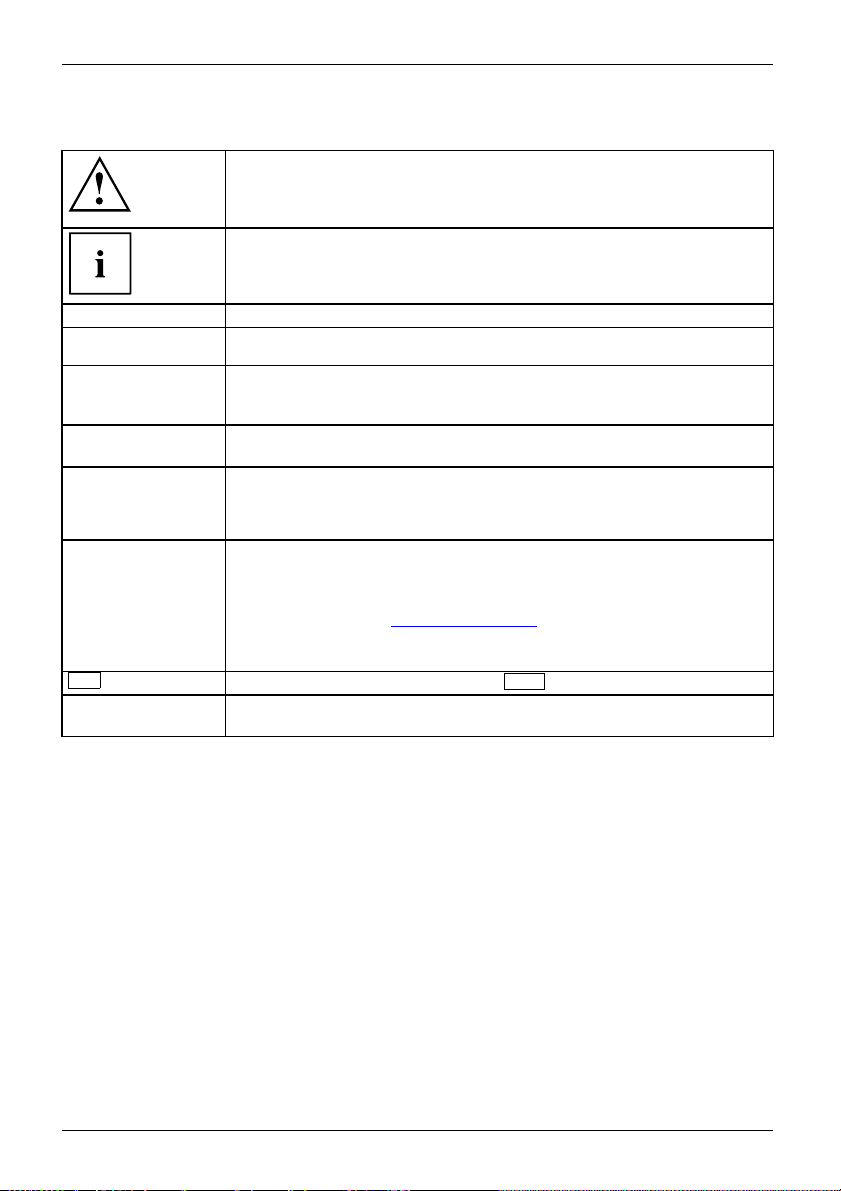
Pay particular attention to text marked with this symbol. Failure to observe
these warnings could pose a risk to health, damage the device or lead
to loss of data. The warranty will be invalidated if the device becomes
defective through failure to observe these warnings.
Indicates importan t informa
tion for the proper use of the device .
►
This font
This font
This font
"This font"
Key
This font
Indicates an activity that must be performed
Indicates a result
indicates data entered
the c ommand line, e.g.
start a program (star
indicates information that is displayed on the screen by a program, e.g.:
Installation is complete.
indicates
• terms an d texts used in a software interface, e.g.: Click on Save
• names of programs or files, e.g. Windows or setup.exe.
indicates
• cross-references to another section, e.g. "Safety information"
• cross-references to an external source, e.g. a web address: For m ore
information, go to "
• Names of CDs, DVDs and titles or designations for other materials,
e.g.: "CD/DVD Drivers & Utilities" or "Safety/Regulations" manual
indicates a key on the keyboard, e.g:
indicates terms and texts that a re emphasised or highlighted, e.g.: Do
not switch off the device
using the keyboard in a program dialogue or at
your password (Name123) or a command used to
t.exe)
http://ts.fujitsu.com"
F10
6 Fujitsu Technology Solutions
Page 11
Important notes
ImportantnotesNotes
In this chapter you will find information regarding safety which it is essential to
take note of when working with your device.
Safety information
SafetyinformationNote
Please note the informat
and in the following safe
When installing and ope
environmental conditi
as the instructions in C
When setting up the dev
thecasingreceives
cover the ventilati
You must only opera
device is set to the
The main switch (if
device from the ma
voltage, remove t
Replace the lit
in "
Replacing t
Caution, compo
The activitie
performed wit
Repairs to th
Incorrect re
to the equip
hium battery on the mainboard in accordance with the instructions
he lithium battery", Page 52.
nents in the system can get very hot.
s described in these instructions must always be
h the greatest care.
e device must only be performed by qualified technicians.
pairs could put the user at great risk or cause serious damage
ment (electric shock, risk of fire).
ion provided in the "Safety/regulations" manual
ty notes.
rating the device, please observe the notes on
ons in Chapter "
hapter "
ice, make sure there is clearance all around it so that
enough ventilation. In order to avoid overheating, do not
on areas of the monitor or the device.
te the device if the rated voltage used by the
local mains voltage.
present) and the ON/OFF switch do not disconnect the
ins voltage. To completely disconnect from the mains
he power plug from the power socket.
Tec hnical specification", Page 53 as well
Getting started", Page 12.
Important notes
Transport
Device,TransportationRetransportation
Fujitsu Technology Solutions 7
ing the device
Transport all parts separately in their original packaging or in a packaging which
protects them from knocks and jolts, to the new site.
Do not unpack th em until all transportation ma noeuvres are completed.
If the device is brought from a cold environment into the room where it will be used,
condensation may occur. Before operating the device, wait until it is absolutely dry
and has reached approximately the same temperature as the installation site.
Page 12
Important notes
Cleaning the device
Device,TransportationRetransportationSystemunit, seeDevice
Turn off all power and equipment switches and disconnect th e power
plug from the mains outlet.
Do not clean any interior parts yourself, leave this job to a service technician.
Do not use any cleaning agents that contain abrasives or may corrode
plastic (alcohol, thinner or acetone).
Never clean the device with water! Water entering into the device could
present a serious risk to users ( e.g. electric shock).
Ensure that no liquid enters the system.
The surface can be clea
moistened in mild dome
Use disinfectant wi
ned with a dry cloth. If part icularly dirty, use a cloth that has been
stic detergent and then carefully wrung out.
pes to clean the keyboard and the mouse.
Energy saving, disposal and recycling
DisposalEnergysavingRecyclingDrivers&UtilitiesDVDUserDocumentationDVD
Further information can be found on the "Drivers & Utilities" DVD.
CE marking
ticcompatibility
rective
CEmarkingCEmarkingNotesElectromagne
Lowvoltagedi
The shipped version of this device complies with the requirements of EEC
directives 2004/108/EC "Electromagnetic compatibility" and 2006/95/EC
"Low voltage directive".
CE marking for devices with radio component
This equipment co mplies with the requirements of Directive 1999/5/EC of the
European Parliament and Commission from 9 March, 1999 governing Radio
and Telecommunications Equipment and mutual recognition of conformity.
This equipment can be used in the following countries:
Belgium Bulgaria Denmark
Estonia Finland France
UK Ireland Iceland Italy
Latvia Liechtenstein Lithuania Luxembourg
Malta Netherlands Norway Austria
Poland Portugal Rumania
zerland
Swit
Czech Republic
Slov
Hun
akia
gary
enia
Slov
Cyprus
Contact the corresponding government office in the respective country for
current information on possible operating restrictions. If your country is
not included in the list, then please contact the corresponding supervisory
authority as to whether the use of this product is permitted in your country.
Germany
Greece
Sweden
n
Spai
8 Fujitsu Technology Solutions
Page 13

Important notes
FCC Compliance Statem ent
If the device complies with the FCC regulations, the FCC sign can be found on the type rating plate.
FCCClassBComplianceState
The following statement applies to the products covered in this manual, unless otherwise specified
herein. The statement for other products will appear in the accompanying docume ntation.
NOTE:
This equipment has been tested and found to comply with the limits for a "Class B" digital
device, pursuant to Part 15 of the FCC rules and meets all requirements of the Canadian
Interference-Causing Equipment Standa rd ICES-003 for digital apparatus. These limits are
designed to provide reasonable protection against harmful interference in a residential installation.
This equipment generates, uses and can radiate radio frequency energy and , if not installed
and used in strict accordance with the instructions, may cause harmful interference to radio
communications. However, there is no guarantee that interference will not occur in a particular
installation. If this eq uipment does cause harmful interference to radio or television reception,
which can be determined b y turning the equipment off and on, the user is encouraged to
try to correct the interference by one or more of the following measures:
• Reorient or relocate the receiving antenna.
• Increase the sep
• Connect the equipment into an outlet on a circuit different from that to
which the receiver is connected.
• Consult the de
Fujitsu Te chn ology Solutions GmbH is not responsible for any radio or television interference
caused by unauthorized modifications of this equipment or the substitution or attachment
of connecting cables and equipment other than those specified by Fujitsu Technology
Solutions GmbH. The correction of interferences cause d by such unauthorized modification,
substitution or attachment will be the responsibility of the user.
The use of shielded I/O cables is required when connecting this equipment to an y and all optional
peripheral or host devices. Failure to do so may violate FCC and ICES rules.
aration betwee n equipment and the receiver.
aler or an experienced radio/TV technician for help.
ment
Fujitsu Technology Solutions 9
Page 14
Ports and operating elements
Ports and operating elements
Ports
This chapter presents the individual hardware components of your device. This will provide
you with an overview of the ports and operating elements on the de vice. Please familiarise
yourself with these components before sta rting to work with your device.
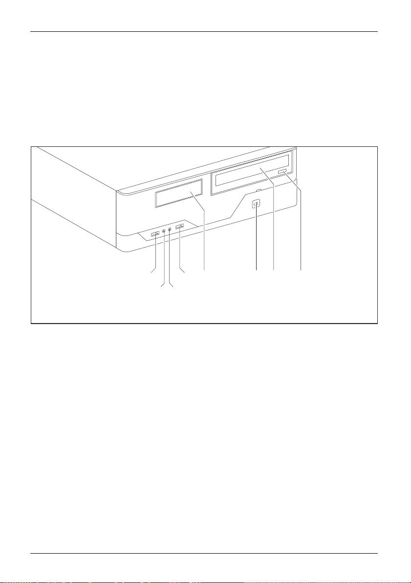
Front
1
2
1 = USB ports
2 = Headphone port
3 = Microphone port
1
4=3
10 Fujitsu Technology Solutions
/2inch module bay
1
4
3
5 = ON/OFF switch
6 = Optical drive (optional)
7 = Insert/eject button (CD/DVD)
56
7
Page 15
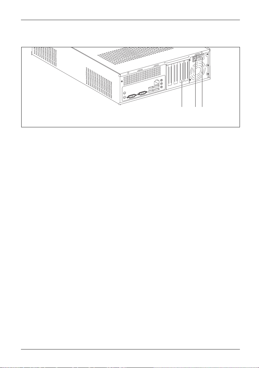
Rear
Ports and operating elements
3
2
1
1 = Slot covers
2 = Main switch
3 = Alternating voltage socket (AC IN)
Fujitsu Technology Solutions 11
Page 16

Getting started
Getting started
Gettingstarted
Unpacking and checking the delivery
It is recommended not to throw away the original packaging material! It may be
required for reshipment at some later date.
PackagingContentsofdeliveryPackaging,
► Unpack all the individual parts.
► Check the contents of the package for any visible damage caused during transport.
► Check whether the delivery conforms to the details in the delivery note.
► Should you discover that the delivery does not correspond to the delivery
Steps for initial setup
Preparingforfirstuse,overvie wPreparingforuse,
Only a few steps are necessary to put your new device into operation for the first time:
• Select a location for device and se t up device
• Connecting external de vice s
• Check the voltage at the mains outlet and co nnect the device to an electrical outlet
• Switch the device on
You will learn more about the individual steps in the following sections.
Please observe the safety information in the "Important notes", Page 7 chapter.
note, notify your local sales out let immediately.
External devices
If you have received other external devices in addition to your own device (e.g.
a printer), do not connect these until after the initial installation. The following
sections describe how to connect these external devices.
Drives and boards
If you have received drives or boards with your device, please do no t install
them until after first-time setup. How to install drives and boards is described
System expansions", Page 31 chapter.
in the "
12 Fujitsu Technology Solutions
Page 17

Settingupthedevice
VideoworkstationErgonomicDevice,
You can set up and operate the device in either a vertical or horizontal position.
When installing your device, please r ead the recommendations and
safety notes in the "Safety" manual.
Use the device simply in the horizontal operating position. With the aid of suitable
feet, it is also possible to use the device in the vertical operating position..
We re commend that you place your device on a surface with good anti-slip qualities.
In view of the multitude of different finishes and varnishes used on furniture, it is
possible that the rubber feet will mark the surface they stand on .
Depending on the location of your device , spurious vibrations and noises may
occur. To prevent this, on casing sides without ventilation surfaces a distance
of at least 10 mm should be maintained from other devices.
To ensure the casing receives adequate ventilation, when setting up the
device make sure that there is sufficient clearance around it as indicated
in the chapter "
In order to avoid overheating, do not cover the ventilation areas
of the monitor or the device.
Do not stack several devices on top of each other.
Do not expose the device to extreme ambient conditions (see "Technical sp ecification",
Page 53, "Ambient conditions"). P ro tect the device against dust, humidity and heat.
Vertical operating position (optional)
Use the optional rubber feet when you wish to use the device in
the vertical operating position.
The set-up direction is compulsory: The ON/OFF switch must be at
the top to ensure sufficient ventilation.
Tec hnical specification " , Page 53.
Getting started
Fujitsu Technology Solutions 13
Page 18

Getting started
Proceed as follows to operate the device in the vertical operating position using th e rubber feet:
ngposition
on,vertical
Verticaloper ati
Operatingpositi
BasefeetSidecover
► Disconnect the cables if required.
► Position the casi
ng vertically so that the ON/OFF switch is located at the bottom.
► Pull off the foil from the rubber feet t hat you will find in the accessories package.
40 mm
1
1
6 mm
1
1
► Affix the rubber feet (1) to the outside of the casing. The positions of the rubbe r feet
must correspond to the dimensions given so that the device is stable.
► Stand t
he device on the rubber feet.
► Reconnect any cables which were disconnected earlier.
14 Fujitsu Technology Solutions
Page 19

Connecting the device to the mains supply
Mainsadapter
1
2
► Connect the power cable to the device (1).
► Plug the po wer plug into a grounded mains outlet (2).
Getting started
Fujitsu Technology Solutions 15
Page 20

Getting started
Connecting external devices
Read the documen tatio n on the external device before connecting it.
With the exception of USB devices, always remove all power plugs
before connecting external devices!
Do not connect or disconnect cables during a thunderstorm.
Always take hold of the actual plug. Never unplug a cable by pulling the cable itself.
Connect and disconnect the cables in the order described below.
Connecting the cables
► Turn off all power and equipment switches.
CordCable,
► Remove all power plugs from the grounded mains outlets.
► Connect all the cables to the device and the external devices. Please make sure that you
always observe the safety notes provided in "
► Plug all data communication cables into the appropriate sockets.
► Plug all power cables into the grounded mains outlets.
USB devices are hot-pluggable. This means you can connect and disconnect
USB cables while your device is switched on.
Additional information can be found in "
ports", Page 19 and in the documentation for the USB devices.
Important notes", Page 7.
Connecting external devices to the USB
Disconnecting the cables
► Switch off al
Cable,
► Remove all power plugs from the grounded mains outlets.
► Unplug all d
► Disconnect all of the cables from the device and from the external devices.
16 Fujitsu Technology Solutions
l affected devices.
ata communication cables fro m the appropriate sockets.
Page 21
Getting started
LAN
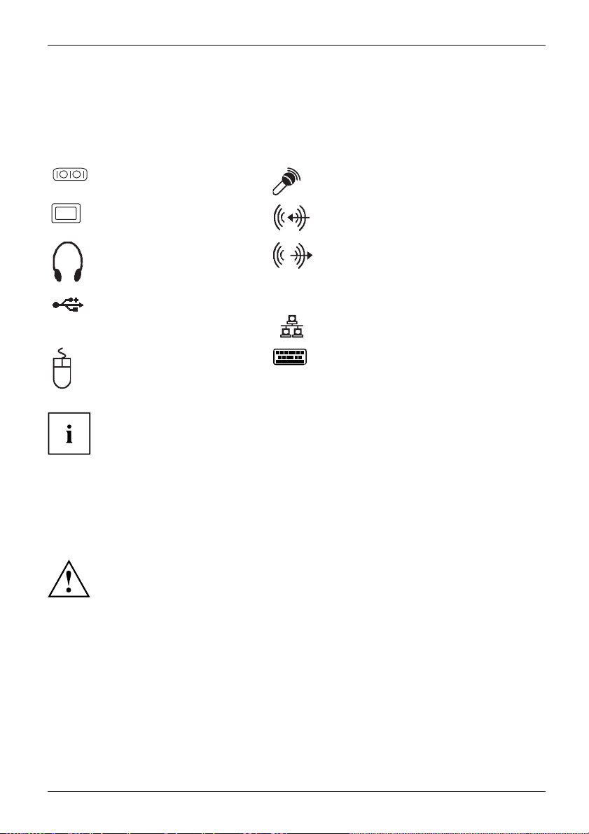
Ports on the device
InterfacesExternaldevices,Device,
The ports are located on the front and back of the device. The ports available on your
device depend on the configuration level you have selected. The standard ports are
marked with the symbols shown below (or similar). Detailed information on the location
of the ports is provided in the manual for the mainboard.
Serial interface , turquoise
Serialinterface
Microphone port, pink
Microphoneport
VGA monitor port, blue
Monitorport
Headphones port, orange or
light green
Headphones
USB - Universal Serial Bus,
black
us
UniversalSerialB
PS/2 mouse port, green
MouseportPS/2mouseport
Audio input (Line In), light blue
AudioinputLinein
Audio output (Line Out), light green
AudiooutputLineout
LAN port
LANport
PS/2 keyboard port, purple
Keyboardport
Some of the connected devices require special drivers (see the
documentation for the connected device).
Connecting a monitor
► Follow the instructions contained in the monitor manual to prepare the monitor
for operation (e.g. connecting cables).
Monitor
► Connect the data cable of the monitor into the monitor port of your device.
The monitor power cable may only be connected to the monitor socket of the
device if the monitor rated current is less than 1.5 A with 230 V or 3 A with
115 V. The values for the monitor rated current can be found in the technical
data on the monitor or in the operating manual for the monitor.
► Depending on the configuration level of your device, plug the monitor power
cable into the grounded mains outlet.
Fujitsu Technology Solutions 17
Page 22

Getting started
Connecting the mouse
Depending on the equipment level selected, your device will be supplied with
a USB mouse or a PS/2 mouse.
Mouse,Connecting,
Connecting a USB mouse
► Connect the USB mouse to one of the USB ports on the device.
USBport,USBport
Connecting a PS/2 mouse
► Connect the PS/2 mouse to the PS/2 mou se port of the device.
PS/2mouse,Connecting,PS/2mouse,
Connecting the keyboard
Depending on the equipm
a USB keyboard or a PS/2 k
Keyboard,Connecting,
Connecting a USB keyb
Use the supplied keyboard cable only.
USBport,Connecting,
► Plug the rectangular connector of the keyboard cable into the rectangular socket
on the underside or on the rear of the keyboard.
► Insert the flat rect
USBport
Connecting a PS/2 keyboard
Use the supplied
ConnectingaPS/2keyboardConnecting,
► Plug the rectang
on the underside
► Plug the round plug of the keyboard cable into the keyboard port on the device.
Keyboard,
Connecting external devices to the serial interface
rface
rface,
vices,
Serialinte
Serialinte
Externalde
Devices,
External devices can be connecte d to the serial interface (e.g. a printer or modem).
► Connect the data cable to the external device.
► Connect the data cable to the corresponding serial interface.
For an exact description of how to connect external devices to the corresponding
port, please see the external device documentation.
ent level selected, your device will be supplied with
eyboard.
oard
angular USB plug of the keyboard cable into one of the device’s USB ports.
keyboard cable only.
ular co nnector of the keyboard cable into the rectangular socket
or on the rear of the keyboard.
Port settings
nterface,
Seriali
You can change the port settings (e.g. address, interrupt) in the BIOS Setup.
Device drivers
Devicedrivers,
ices connected to the serial interface require drivers. Your operating system
The d ev
y includes many drivers. If the required drive is missing, install it. The latest
alread
rs are u sua lly available on the Internet or will be supplied on a data carrier.
drive
18 Fujitsu Technology Solutions
Page 23

Getting started
Connecting external devices to the USB ports
USBdevices,USBport,Externaldevices,Devi ces,
You can connect a wide range of external d evices to the USB ports (e.g.
printer, scanner, modem or keyboard).
USB devices are hot-pluggable. This means you can connect and disconnect
USB cables while your device is switched on.
Additional information can be found in the documentation for the USB devices.
► Connect the data cable to the external device.
► Connect the data cable to one of the USB ports on your device.
Device drivers
The external USB devices you connect to the USB ports usually require no
driver of their own, as the required software is already included in the operating
system. However, if the external USB dev ice requires its own software, please
install it from the data carrier provided with the USB device.
To ensure the transmission capacity of USB 2.0, the cable from the external USB
device to the USB port of your device must not be longer than 3 m.
Switchingonforthefirst time: installing the software
Installing,Software,Installing,
Once the installation has been started the device must not be switched
off, unless the installation has been completed.
During installation, the device may only be rebooted whe n you are requested to do so!
The installation will otherwise not be carried out correctly and the contents
of the hard disk must be completely restored.
is integrated into a network, the user and server details as well as
protocol are required during the software installation.
r network administrator if you have any questions about these settings.
itch on the device for the first time, the supplied software
ed and configured. Plan a reasonable amount of time for this,
cess must not be interrupted.
You may ne
number i
s located on a sticker on your device.
If the devic e
the network
Contact you
When you sw
is install
as this pro
ed the licence number for Windows during the installation. The licence
Fujitsu Technology Solutions 19
Page 24

Getting started
Switching on monitor and device
In order to avoid overheating, do not cover the ventilation areas
of the monitor or the device.
Depending on the version, the device may be equipped with a main power switch
on the back of the device in addition to the ON/OFF button on the front.
► Switch the monitor on (see the operating manual for the monitor).
► Switch the device on. To do this, follow the instructions below.
1
2
► Turnthemainswitchonthebackofthedevicetothe"I"position(1).
► Press the ON/OFF switch on the front of the device (2).
The power-on indicator lights green and the device is started.
Installing the software
► During installation, follow the on-screen instructions.
Software,Installing,
► If anything is unclear regarding the data you are asked to input, read the
online Help in your operating system.
You will find more information on the system, as well as drivers, utilities and updates on
the "Drivers & Utilities" DVD and on the Internet under "
20 Fujitsu Technology Solutions
http://ts.fujitsu.com/support/".
Page 25

Operation
Switch the device on
► If necessary, switch the monitor on (see the operating manual for the monitor).
Device,Monitor,
► Switch on the device using t
► Press the ON/OFF switch on the front of the device.
The power-on indicator
Switching off the device
► Shut down the operating system in a defined manner. In Windows: via the
Start menu and the Turn Off Computer function.
Device,Monitor,
► If the operating sy
switch it off, pres
If the device is switched off, it consumes a minimum of energy.
► Switch the device
The device no longer uses any power.
The main switch and the ON/OFF s witch d o not disconnect the device
from the mains voltage. To completely disconnect from the mains voltage,
remove the power plug from the power socket.
stem does not automatically switch the device into energy-saving mode or
s the ON/OFF switch. Warning, this could lead to a loss of data!
offatthemainswitch(ifpresent).
he main power switch located on the rear of the device (if present).
lights gre en and the device is started.
Operation
► If necessary, switch the monitor off (see the operating manual for t he monitor).
Indicators on the device
Indicators,Device
The indicators are on the front of the casing. Which indicators are available on your
device depends on the configuration level you have selected.
Fujitsu Technology Solutions 21
Page 26

Operation
1 = Indicator for diskette drive or multi-card
reader (depending on the configuration
level of the device)
123
3 = Hard disk indicator
4 = Drive indicator, e.g. DVD
4
2 = Power-on indicator
Hard disk indicator
The indicator lights up when the hard disk drive of the device is accessed.
Power-on indicator
Power-onindicatorPower-onindicatorPower-onindicatorPower-onindicatorPower-onindicator
In energy-saving mode the device must not be switched off with the main power switch
(if present) or disconnected from the mains, a s this may result in data loss.
• The indica
tor is lit green: The device is on.
• The indicator flashes green: The device is in power-saving mode. After being
switched on with the ON/OFF switch, the device powers up or returns to the
state it was in before it entered power-saving mode.
• The indic
Diskett
configu
DiskettedriveMulti-cardreaderindicator
The ind
access
Drive
DVDindicatorDVD indicatorCD-ROMindicatorCD-ROM drive
The in
Neve
ator is not lit: The device is switched off.
e drive indicator or multi-card reader indicator (depending on the
ration level of the device)
icator lights up when the diskette drive or the multi-card reader of the device is
ed. Never rem ove a diskette or a multi-card while the indicator is lit.
indicator, e.g. DVD
dicator lights up when the CD-ROM or DVD drive of the device is accessed.
r remove a DVD while the indicator is lit.
22 Fujitsu Technology Solutions
Page 27

Keyboard
KeyboardKeyboar d,Keyboard,Keyboard,Keyboard,K eyboard,Alphanumerickey padCursorkeysKeys,FunctionkeysNumerickeypadNumerickeypad
The illustrated keyboard is an example and may differ from the model you use.
Operation
1 2
345
1 = Function keys
2 = On/off switch (optional)
3 = Alphanumeric keypad
4=Cursorkeys
5 = Numeric keypad (calculator keypad)
Fujitsu Technology Solutions 23
Page 28
Operation
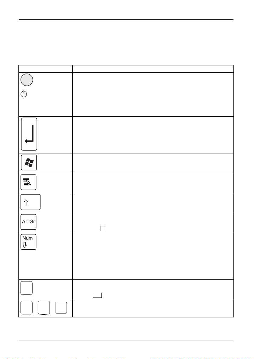
Important keys and keyboard shortcuts
KeysKeyboardshortcuts
The description of the following keys and keyboard shortcuts applies to Microsoft
operating systems. Details of other keys and keyboard shortcuts can be found in
the documentation for the relevant application program.
Key / key combination Description
ON/OFFswitchBut ton,
On/off switch (optional)
Depending on the setting in the BIOS Setup, the device can be switched
on or off with this switch. Some operating systems allow you to configure
additional functions of the ON/OFF switch in the Control Panel.
WithsomekeyboardstheON/OFFswitchcanonlybeusedwithanACPI
(Advanced C onfiguration an d Power Management Interface). Otherwise
the key is inoperative. The mainboard must support this function.
Keys,Keys,Keys,
Enter key
confirms the highlighted selection. The Enter key is also r eferred to as
the "Return" key.
Start key
Keys,
calls up the Windows Start menu.
Keys,
Menu key
calls up the menu for the marked item (Windows).
Keys,Keys,
Shift key
enables upper-case letters and the upper key symbols to be displayed.
Keys,
Alt Gr key
produces a character shown on the bottom right of a key (e.g. the @
sign on the
Keys,
Q
key).
Num Lock key
By pressing the Num Lock key you switch between the upper- and
lower-case levels of the calculator keypad.
When the Num Lock indicator is lit the numeric keypad and arithmetic
keys are active.
When the Num Lock indicator is not lit the cursor control functions on the
Numeric keypad are active.
Keys,KeysKeysKeys,
Ctrl key
Ctrl
AltCtrl
++
performs a special operation when pressed in conjunction with another
Ctrl
key. The
Ctrl+Alt+DelCtrl+Alt+DelKeyskeyboardshortcuts
Windows security/Task-Manager
Del
This key combination opens the Windows Security/Ta sk Manager window.
key i s also called the "Control" or "Control k ey".
24 Fujitsu Technology Solutions
Page 29

Operation
Settings in BIOS Setup
BIOSSetup,Syst e msettings,BIOSSetup,BIOSSetup,BIOS SetupSetup,
In BIOS Setup, you can set the system functions and the hardware configuration of the device.
When the PC is delivered, the default entries are valid (see "BIOS Setup" manual or manual for
the mainboard). You can customise these settings to your requirements in the BIOS Setup.
Property and data protection
PropertyprotectionDataprotectionSecuritymeasures
Software functions and mechanical locking offer a broad range of functions for protecting your
device and your personal data from unauthorised access. You can also combine these functions.
Anti-theft protection and lead-sealing
Device,Device,Casi ng,Lead-seali ngAnti-theftprotectionKensingtonLockChain
1
2
1 = Holes for padlock 2 = Fixture for Kensington Lock
Anti-theft protection
You can protect your device from theft
• with the holes (1), a padlock and a chain, which you have connected to a fixed object before hand.
• with the Kensington Lock device (2) and a Kensington MicroSaver. Consult
the manual for your Kensington L o ck.
Lead-sealing
The casing can be sealed to prevent it being opened by unauthorised persons. To do this, feed
the sealing chain through the holes (1) and seal the chain with the lead seal.
Fujitsu Technology Solutions 25
Page 30

Problem solutions and tips
Problem solutions and tips
Comply w ith the safety information in the "Safety" manual and the chapter
Getting started", Page 12, when attaching o r detaching cables.
"
If a fault occurs, try to r
• in this chapter
• in the documentation relating to the peripheral devices
• in the Help sections fo
• in the documentation for the operating system in use.
ectify it in accordance with the measures described in the following documents:
r the individual prog rams
Help if problems occur
Should you encoun
► Note the ID number
plate on the back
► For further clarification of the problem, c ontact the Service Desk for your country (see the
Service Desk list or go to "
this, please have ready the ID number and serial numbe r of your system.
ter a problem with your computer that you cannot resolve yourself:
of your device. The ID number is found on the type rating
, the underside or the top of the casing.
http://ts.fujitsu.com/support/servicedesk.html"). When you do
Troubleshooting
Power indica tor remains off after you have switched on your device
Cause
The mains voltage supply is faulty. ► Check that the power cable is correctly
Internal power supply overloaded.
Remedy
plugged into the device and into a grounded
mains outlet.
► Check that the main switch a t the rear of the
monitor is set to the "I" position.
► Switch the device on.
► Pull the power plug of the device out of the
mains outlet.
► Wait a
► Plug the power plug into a properly grounded
► Swit
moment.
mains outlet again.
ch the device on.
26 Fujitsu Technology Solutions
Page 31

Problem solutions and tips
The device cannot be switched off with the ON/OFF switch
Cause
The device has not been switched on with the
ON/OFF switch.
System crash ► Keep the on/off switch pressed for at least
Remedy
► Press the ON/OFF switch again.
4 seconds until the machine switche s off.
Caution: This can lead to a loss of data!
This procedure does not allow the operating
system to shut down in an orderly way. The next
time the system is started there may well be
error messages.
Monitor remains blank
Cause
Monitor is switched off. ► Switch your mo nitor o n.
Power saving has been activated (screen is
blank)
Brightness control is se t to dark ► Adjust the brightness control. For detailed
Power cable not connected
Monitor cable not connected
Remedy
► Press any key on the keyboard.
or
► Deactivate the screen saver. If
necessary, enter the appropriate
password.
information, please refer to the operating
manual supplied with your monitor.
► Switch off the monitor and the device.
► Check that the monitor power cable is
properly connected to the monitor and to
a grounded mains outlet or to the monitor
socket of the device.
► Check that the device power cable is
properly plugged into the device and a
grounded mains outlet.
► Switch on the monitor and the device.
► Switch o
► Check that the monitor cable is properly
connected to the device and monitor.
► Switch
ff the monitor and the device.
on the monitor and the device.
Fujitsu Technology Solutions 27
Page 32

Problem solutions and tips
Cause
Remedy
Wrong monitor has been set under Window XP ► Restart the device.
► Press
F8
while the system is booting.
Either the Windows Advanced Start Options menu
or the m enu for selecting the operating system
appears.
► If the menu for selecting the operating
system appears, press
► Select Safe Mode or Safe Mode with Network.
► Go to Start – Settings – Control Panel – Display
and the tabs Appearance, Themes, Settings
to set the correct values for the connected
monitor as described in the operating
manual of the monitor.
Incorrect setting fo
r the monitor in Windows Vista
► Restart the device.
► Press
F8
while the system is booting.
Either the Windows Advanced Start Options menu
or the m enu for selecting the operating system
will appear.
► If the menu for selecting the operating
system appears, press the
► SelectSafe Mode or Safe Mode with Network.
► Go to Start symbol – (Settings) – Control
Panel – Appearance and Personalization –
Personalization and enter the correct values
for the connected monitor as described in
the operating manual of the monitor.
Wrong monitor has been set under Windows 7 ► Restart the device.
► Press
F8
while the system is booting.
Either the Windows Advanced Start Options menu
or the m enu for selecting the operating system
appears.
► If the menu for selecting the operating
system appears, press
► Select Safe Mode or Safe Mode with Network.
► Go to Start – Control Panel – Appearance
and Personalization – Display to enter the
correct values for the connected monitor as
described in the operating manual of the
monitor.
F8
F8
.
F8
key.
.
28 Fujitsu Technology Solutions
Page 33

No mouse pointer displayed on the screen
Cause
The mouse is not correctly connected.
The mouse controller is not enabled.
Remedy
► Shut down the operating system properly.
► Switch the device off.
► Check that the mouse cable is properly
connected to the system unit. If you use an
adapter or extension lead with the mouse
cable, check the connections.
► Make sure that only one mouse is
connected.
► Switch the device on.
► Check in the BIOS-Setup whether the mouse
controller is enabled.
► Check that the mouse dr
installed and is pres
programme is starte
can be found in the us
and application pro
Problem solutions and tips
iver is properly
ent when the application
d. Detailed information
er guide for the mouse
gramme.
Time and/or date i
Cause
Time and date are incorrect.
The lithium battery is discharged.
s not correct
Remedy
► Set the correct time and date within the
operating system you are using.
or
► Set the correct time and/or date in th e
BIOS Setup.
► If the time and date are repeatedly wrong
when you switch on your device, replace the
lithium battery (see "
battery", Page 52).
Error messages on the screen
Error mes
•inthete
• in the documentation for the programs used
sages and their explanations are provided:
chnical manual for the mainboard
Installing new software
nstalling programs or drivers, important files may be overwritten and modified. To
When i
e to access the original data in the event of any problems following installation,
be abl
hould backup your hard disk prior to installation.
you s
Replacing the lithium
Fujitsu Technology Solutions 29
Page 34

Problem solutions and tips
Restoring the hard disk content
The instructions on how to restore the content of the hard disk drive under Windows 7
can be found in the "Recovery Guide" manual.
s
Tips
Top i c Tip
Out of system resources ► Close unnecessary applications.
or
► Run the applications in a different order.
Other manuals Further manuals are provided as PDF files on
the "Drivers & Utilities" DVD.
30 Fujitsu Technology Solutions
Page 35

System expansions
System expansions
Upgrades,Device,SystemexpansionCom ponentsServicing
After con sulting the Hotline/Help Desk, you may remove a nd install the components
described in this manual yourself.
The following illustrations may differ slightly from your device, depending on its configuration level.
If further documentation was delivered with your device, please also read this through carefully.
In addition, before removing or installing system components, please pay attention to the following:
Repairs to the device must only be performed by qualified technicians. Incorrect repairs
may greatly endanger the user (electric shock, fire risk) and will invalidate your warranty.
As the device has to be shut down in order to install/deinstall system hardware
components, it is a good idea to print out the relevant sections of this chapter beforehand.
The device must be switched off when installing/removing the system
expansions and may not be in en ergy-saving mod e.
Remove the power plug before opening the device.
Be careful that no wires become trapped when removing or installing compone nts.
When installing components that become very hot, make sure that the maximum
permissible temperature of the components in operation is not exceeded.
An update of the BIOS m a y be required for a system expansion or hardware
upgrade. Further information can be found in the BIOS help section or if
necessary in the Technical Manual for the mainboard.
Fujitsu Technology Solutions 31
Page 36

System expansions
Information about boards
Take care with the locking mechanisms (catches and centring pins) when you
are replacing boards or components o n boards.
Note that some components on the mainboard may be very hot if the device was
in use shortly before the casing was removed.
To prevent damage to the board or the components and conductors on it, please take care when
you insert or remove boards. Make sure expansion boards are inserted straightly.
Never use sharp objects (screwdrivers) for leverage.
Boards with electrostat
shown.
When handling boards fit
following points:
• You mu st always disc
object) before work
• The eq uipment and tools you use must be free of static charges.
• Only touch or hold t
marked green (Touc
• Never touch pins or conductors on boards fitted with ESDs.
ic sensitive devices (ESD) are identifiable by the label
ted with ESDs, you must always observe the
harge static build up (e.g. by touching a grounded
ing.
he boards by the edge or, if present, at the areas
h Points).
32 Fujitsu Technology Solutions
Page 37

Opening the casing
Removing a cover
► Switch the device off.
The device must not be in the energy-saving mode!
► Remove any plugged-in wires which are in the w ay.
System expansions
1
1
► Loosen the s crews (1).
2
3
► Pull the cover a small distan ce in the direction indicated by the arrow (2) and remove it (3).
Fujitsu Technology Solutions 33
Page 38

System expansions
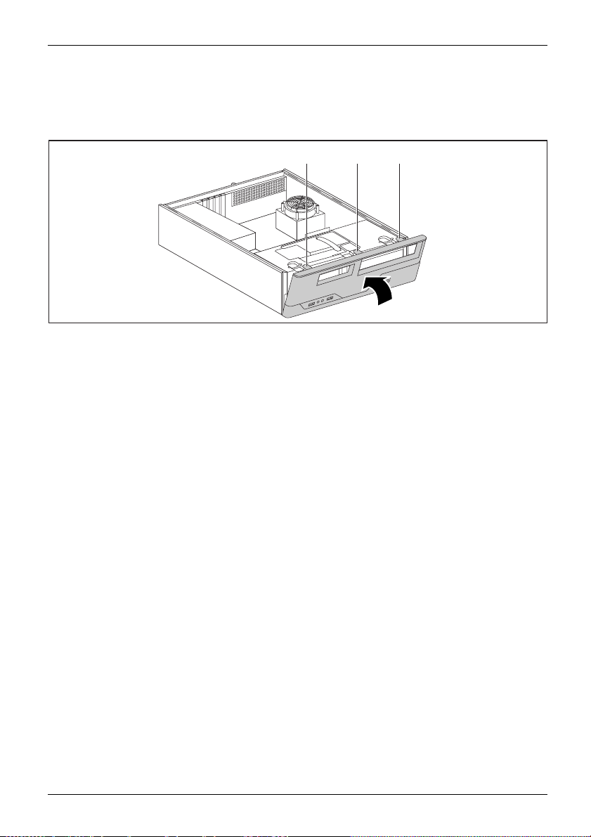
Removing the front panel
► Lift the locking lugs on the front panel (1).
1
1
1
2
► Fold the front panel in the direction of the arrow (2) and remove it from the casing.
34 Fujitsu Technology Solutions
Page 39
Close the casing
Securing the front panel
System expansions
a a a
1
► Place the front p
► Fold the front panel in the direction of the arrow (1) until the catches (a) engage.
anel with the three lower hooks in the front lower guide openings on the casing.
Fujitsu Technology Solutions 35
Page 40

System expansions
Reattaching the cover
2
1
► Place the cover on t
► Fasten the screws (1).
► Connect the cables to the device.
he casing (1) and push it into place in the direction indicated by the arrow (2).
1
1
36 Fujitsu Technology Solutions
Page 41
System expansions
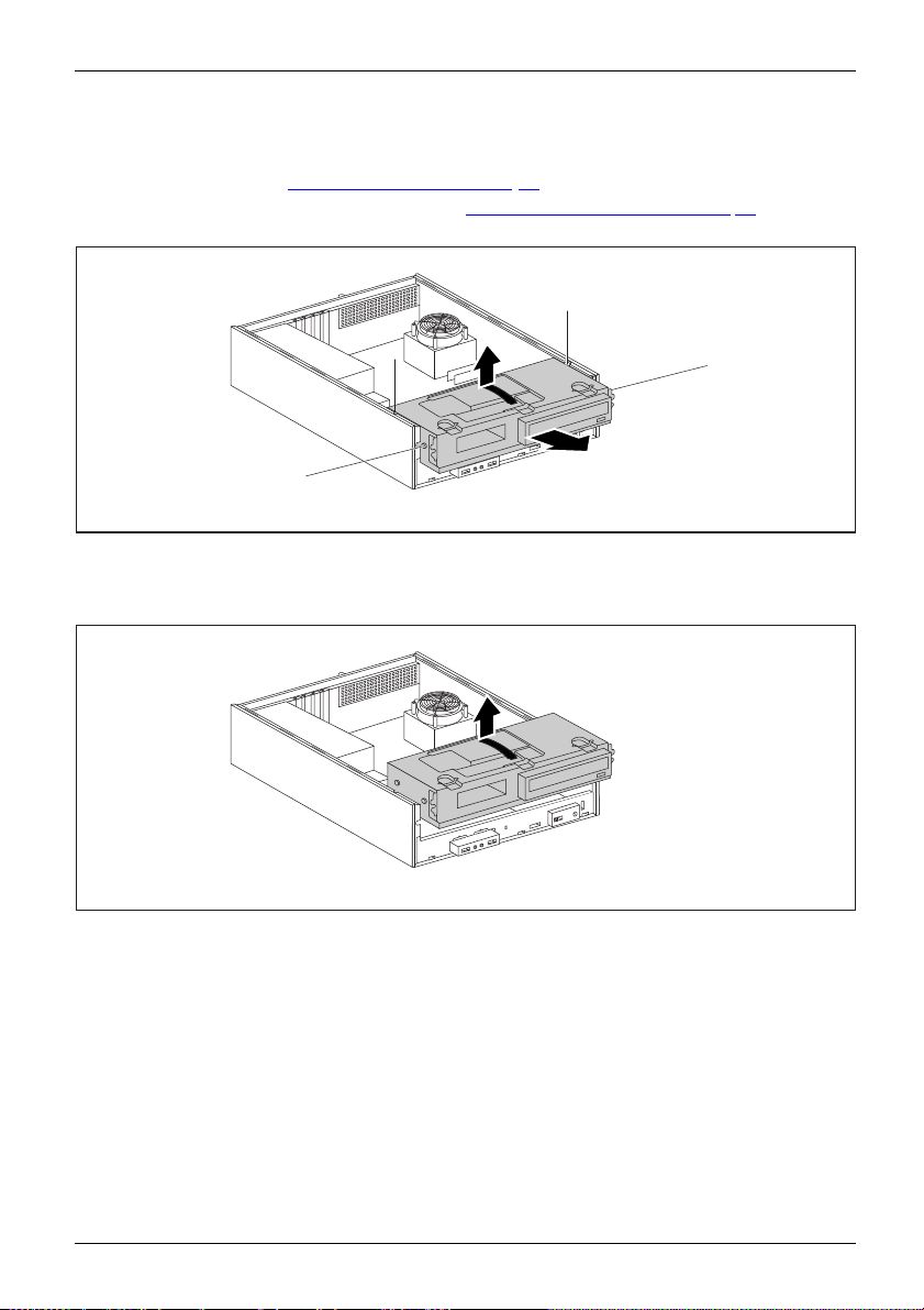
Removing the drive carrier
Removing
► Open the casing (see "Opening the casing", Page 33).
► Remove the front panel from the casing (see "
► If drives are installed, disconnect their data cable and power supply cable plugs.
Removing the front panel", Page 3 4).
a
a
1
a
2
a
► Slightly lift the drive cage using the plastic handle (1).
► Slide the drive cage in the direction of the arrow (2) until the guides (a) are the
same height as the corresponding openings in the casing.
3
► Use the plastic handle to lift the drive cage out of the casing (3).
Fujitsu Technology Solutions 37
Page 42
System expansions
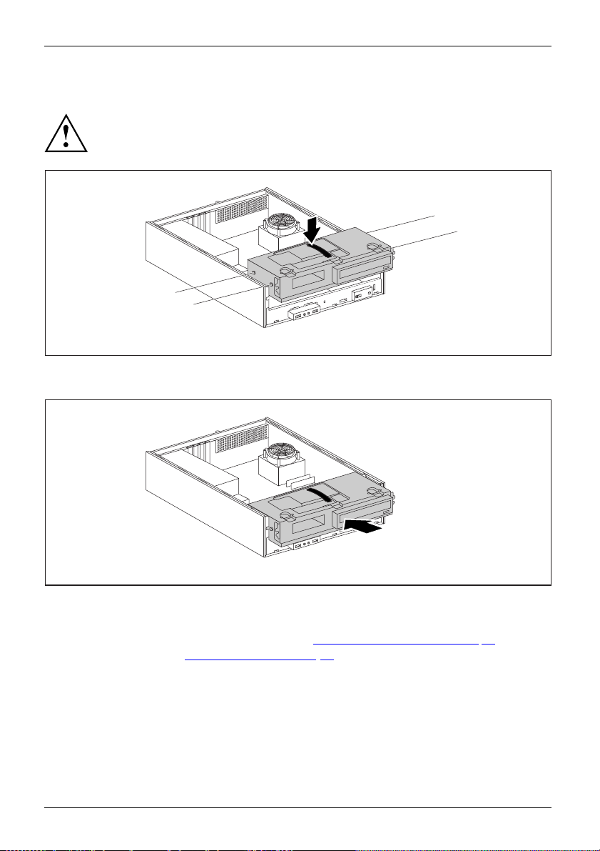
Installing the drive cage
Drivecage
► Insert the drive cage on the plastic handle into the casing (1). When doing so, ensure that
Take care not to trap any cables when installing the drive cage.
a
1
a
a
the guides (a) are at the he ight of the corresponding openings on the casing.
a
2
► Push the drive cage into the casing in the direction of the arrow (2).
► Connect the cables to the drive cage.
► Secure the front panel on the casing again (see "
► Close the casing (see "
Close the casing", Page 35).
Securing the front panel", Page 35).
38 Fujitsu Technology Solutions
Page 43

System expansions
Installing and removing drives
The casing can accommodate a total of three drives:
• one accessible 5
• an accessible or non-accessible 3
• a non-accessible drive
"Accessible drives" are e.g. DVD or CD ROM drives, into which a data medium can be inserted
from outside. "Non-accessible drives" are for example hard disk drives.
Removing and installing accessible drives
The number of screws used to attach the drives varies according to the type of
drive fitted and may not necessarily match the depiction below.
1
/4inch drive
1
/2inch drive or 21/2inch drive
Fujitsu Technology Solutions 39
Page 44

System expansions
Removing an accessible 51/4inch drive (e.g. DVD drive)
► Remove the cover (see chapter "Removing a cover", Page 33).
► Remove the front panel (see chapter "
► Remove the drive cage (see chapter "
► Turn the drive cage over.
1
► Undo the screws (1).
► Pull the drive out of the drive cage in the direction of t he arrow (2).
► If necessary, make the required settings on the remaining hard disk drives.
► If you are not planning to install a new drive, install the corresponding drive cover in
the front panel (if available). To do this, insert the drive cover from behind into the front
panel and press the latches gently into their respective retainers.
► Install the drive cage (see chapter "
► Secure the front panel on the casing (see chapter "
► Install the cover on the casing aga in (see chapter "
Removing the front panel", Page 34).
Removing the drive carrier", Page 37).
1
1
2
Installing the drive cage", Page 38).
Securing the front panel" , Page 35).
Reattaching the cover", Page 36).
It may be necessary to modify the ent ry for the drive in the BIOS Setup.
40 Fujitsu Technology Solutions
Page 45
System expansions
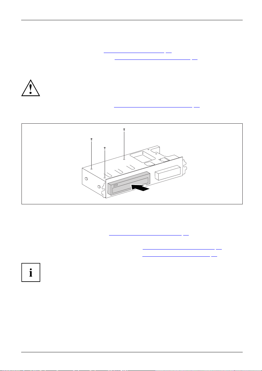
Installing an accessible 51/4inch drive (e.g. DVD drive)
► Remove the cover (see chapter "Removi ng a cover" , Page 33).
► Remove the front panel (see chapter "
► Remove the drive cover if one is fitted. To do this, press the corresponding drive cover
lightly out forwards and pull the drive cover forward out of the front panel.
Do not throw away the covers. If you remove the drive again, you must reinstall the
covers (cooling, fire protection or EMC regulations to be complied with).
EMC,electromagneticcompatibility
► Remove the drive cage (see chapter "Removing the drive carrier", Page 37).
► Turn the drive cage over.
► Take the new drive out of its packaging.
2
Removing the front panel", Page 34).
2
2
1
► Slide the new drive into the drive cage (1) until the stop. Make sure that the screw
holes of the drive cage and of the drive are aligned.
► Fasten the screws (2).
► Install the drive cage (see chapter "
Installing t he drive cage", Page 38).
► Plug the data and the power supply conne ctors into the drive. Make sure the polarity is correct.
► Secure the front panel on the casing (see chapter "
► Install the cover on the casing again ( see chapter "
Securing the front panel", Page 35).
Reattaching the cover", Page 36).
It may be necessary to modify the entry for the drive in the BIOS Setup.
Fujitsu Technology Solutions 41
Page 46
System expansions
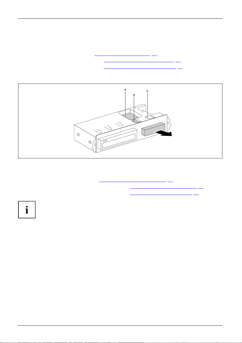
Removing an accessible 31/2inch drive (floppy disk drive or multicard
reader) or a non-accessible 3
► Remove the cover (see chapter "Removing a cover", Page 33).
► Remove the front panel (see chapter "
► Remove the drive cage (see chapter "
► Disconnect all cables connected to the drive (data cable, power supply cable).
► Turn the drive cage over.
► Remove the screws (1).
► Pull the drive out of the drive cage in the direction of t he arrow (2).
► Install the drive cage (see chapter "
► Secure the front panel on the casing (see chapter "
► Install the cover on the casing aga in (see chapter "
It may be necessary to modify the ent ry for the drive in the BIOS Setup.
1
/2inch driv e (hard d isk)
Removing the front panel", Page 34).
Removing the drive carrier", Page 37).
1
Installing the drive cage", Page 38).
1
1
2
Securing the front panel" , Page 35).
Reattaching the cover", Page 36).
42 Fujitsu Technology Solutions
Page 47

System expansions
Installing an accessible 31/2inch drive (floppy disk drive or multicard
reader) or a non-accessible 3
► Remove the cover (see chapter "Removi ng a cover" , Page 33).
► Remove the front panel (see chapter "
► Remove the drive cover if one is fitted. To do this, press the corresponding drive cover
lightly out forwards and pull the drive cover forward out of the front panel.
► Remove the drive cage (see chapter "
► Turn the drive cage over.
► Slide the drive into the casing (1). Make sure that the s crew holes of the
drive cage and of the drive are aligned.
► Fasten the drive into place with the screws (2).
► Install the drive cage (see chapter "
► Plug the data and the power supply conne ctors into the drive. Make sure the polarity is correct.
► Secure the front panel on the casing (see chapter "
► Install the cover on the casing again ( see chapter "
1
/2inch drive (hard disk)
Removing the front panel", Page 34).
Removing the drive carrier", Page 37).
2
Installing t he drive cage", Page 38).
2
2
1
Securing the front panel", Page 35).
Reattaching the cover", Page 36).
It may be necessary to modify the entry for the drive in the BIOS Setup.
Fujitsu Technology Solutions 43
Page 48
System expansions
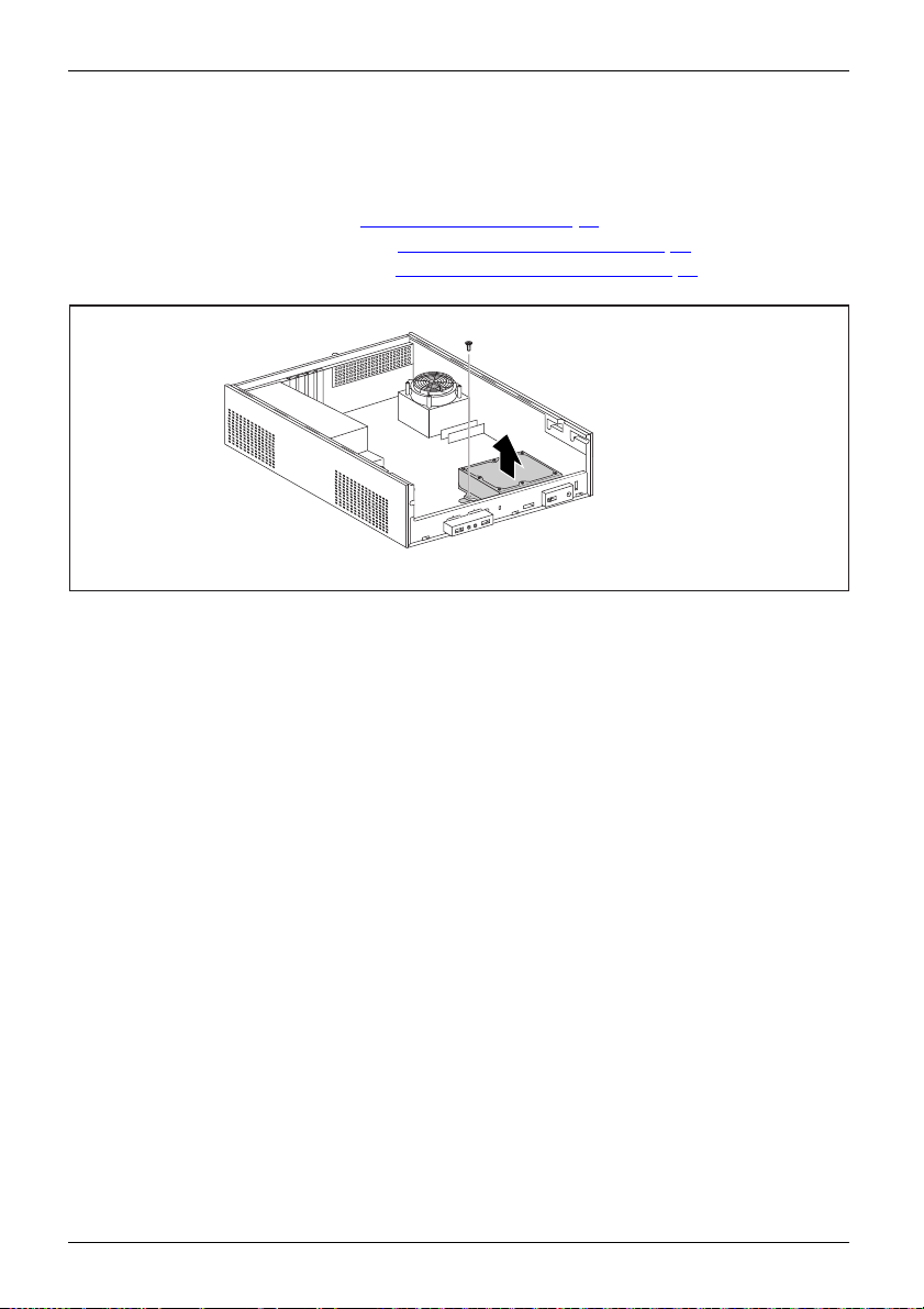
Removing a hard disk drive
Removing the hard disk drive cage
► Remove the cover (see chapter "Removing a cover", Page 33).
► Remove the front panel (see chapter "
► Remove the drive cage (see chapter "
► Disconnect the cables from the m ainboard.
► Undo the screw (1).
► Take the hard di
sk drive cage out of the casing (2).
Removing the front panel", Page 34).
Removing the drive carrier", Page 37).
1
2
44 Fujitsu Technology Solutions
Page 49

System expansions
Releasing the hard disk drive cage from the hard disk drive
1
1
2
► Undo the screws (1).
► Remove the hard disk drive cage from the hard disk drive (2).
► Install the drive cage (see chapter "
► Secure the front panel on the casing (see chapter "
► Install the cover on the casing again ( see chapter "
It may be necessary to modify the entry for the drive in the BIOS Setup.
If you are not planning to install a new hard disk drive, secure the screws in the thre aded
bores on the underside of the hard disk drive cage so that they are not lost.
Installing t he drive cage", Page 38).
1 1
Securing the front panel", Page 35).
Reattaching the cover", Page 36).
Fujitsu Technology Solutions 45
Page 50
System expansions
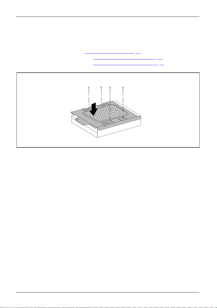
Installing a hard disk drive
Secure the hard disk drive cage on the hard disk drive
► Remove the cover (see chapter "Removing a cover", Page 33).
► Remove the front panel (see chapter "
► Remove the drive cage (see chapter "
► Take the new hard disk drive out of its packaging.
► Place the hard disk drive cage on the hard disk drive (1).
► Fasten the screws (2).
Removing the front panel", Page 34).
Removing the drive carrier", Page 37).
2
2
1
2 2
46 Fujitsu Technology Solutions
Page 51

Installing the hard disk drive cage
2
► Insert the hard disk drive cage into the casing (1).
► Tighten the screw (2).
► Plug in the cables on the hard disk.
► Install the drive cage (see chapter "
► Connect the cables to the drive cage.
► Secure the front panel on the casing (see chapter "
► Install the cover on the casing again ( see chapter "
It may be necessary to modify the entry for the drive in the BIOS Setup.
Installing t he drive cage", Page 38).
System expansions
1
Securing the front panel", Page 35).
Reattaching the cover", Page 36).
Fujitsu Technology Solutions 47
Page 52

System expansions
Installing and removing heat si
nks
Removing the heat sink
► Remove the cover (see chapter "Removing a cover", Page 33).
► Disconnect the fan cables from the mainboard.
► Undo the screws (1).
1
1
1
2
► Install the cover on the casing aga in (see chapter "
1
► Remove the heat sink from the casing (2).
Reattaching the cover", Page 36).
Installing the heat sink
► Remove the cover
2
(see chapter "
2
2
Removing a cover", Page 33).
► Insert the heat sink into the casing (1).
2
To do this, correctly align the screw
holes on the heat sink with the screw
holes on the mainboard.
► Fasten the scr
ews (2).
1
► Connect the fan cables to the mainboard.
► Install t
48 Fujitsu Technology Solutions
he cover on the casing again (see chapter "
Reattaching the cover", Page 36).
Page 53

System expansions
Assembling and dismantling low-profile units
Low-profileboard
For every slot there is a slot cover provided. If no board is installed, t he slot cover protects the slot.
When you install a board, do not discard the corresponding slot cover.
For cooling, protection against fire and in order to comply with EMC regulations,
you must refit the slot cover if you remove the board.
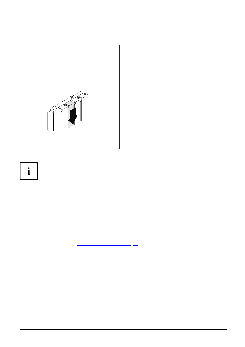
Removing a slot cover
► Open the casing (see "Opening the casing", Page 33).
► Undo the screw (1).
► Pull the slot cover out of th e slot (2).
1
2
Fujitsu Technology Solutions 49
Page 54
System expansions
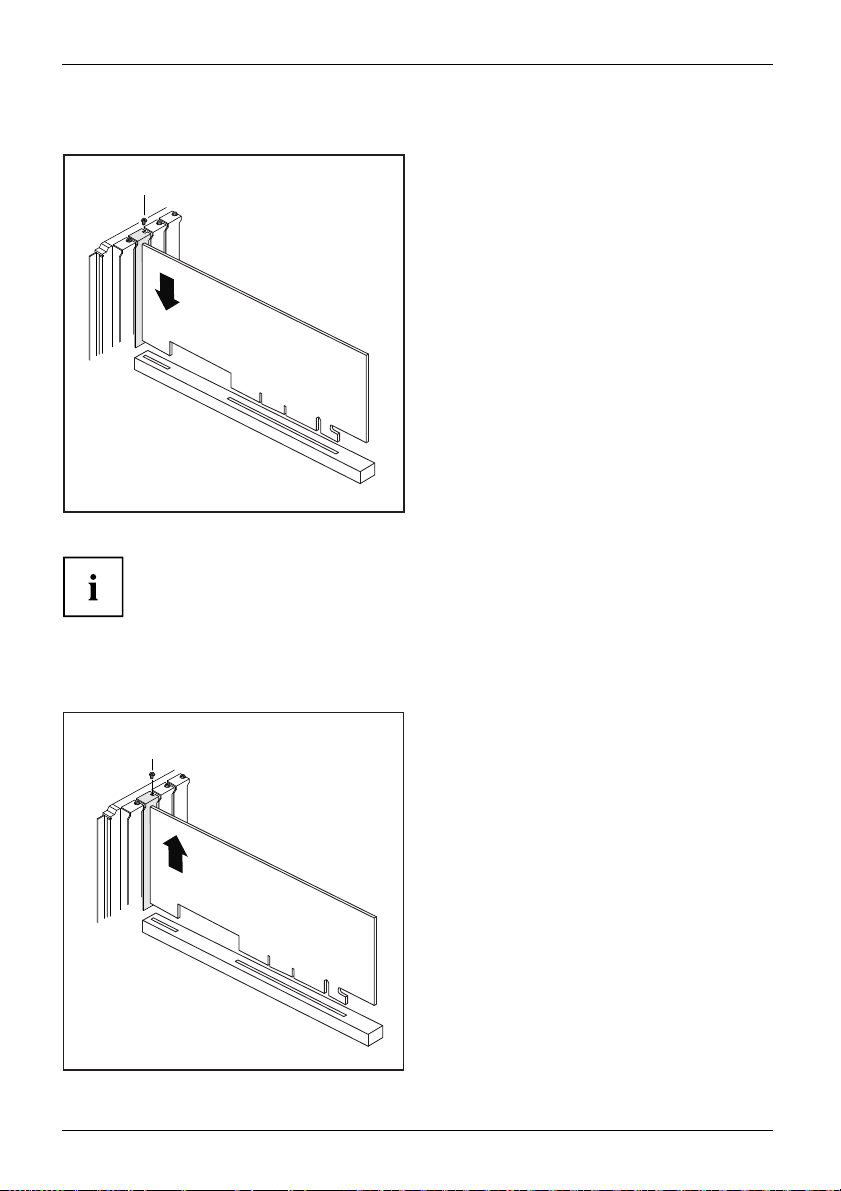
Installing a board
2
1
► If necessary, connect the cables to the board.
If you have installed or removed a board, please check the relevant PCI
slot settings in the BIOS Setup. If necessary, change the settings. Further
information is provided in the PCI board documentation.
► Push the board into the slot (1)
until it engages.
► Tighten the screw (2).
Removing boards
► If necessary, disconnect the cables which are connected to the board.
► Loosen the screw (1).
1
2
50 Fujitsu Technology Solutions
► Pull the board out of the slot (2).
► Place the board in suitable packaging.
Page 55
Reinstalling a slot cover
2
1
System expansions
► Push the slot cover into the slot (1).
► Tighten the screw (2).
► Close the casing (see "
Close the casing", Page 35).
If you have installed or removed a board, please check the relevant PCI
slot settings in the BIOS Setup. If necessary, change the s ettings. Further
information is provided in the PCI board documentation.
Mainboard expansions
Details on how to upgrade the main memory or the processor of your device
can be found in the manual for the mainboard.
UpgradesLi thiumbatteryProcessorMainmemoryMainboard
Upgrading main memory
► Open the casing (see "Opening the casing", Page 33).
Mainmemory,
► Upgrade the memory according to the description in the manual for the mainboard.
► Close the casing (see "
Processor, replacing
► Open the casing (see "Opening the casing", Page 33).
Processor,replacin g
► Upgrade the processo r according to the description in the manual for the mainboard.
► Close the casing (see "
Close the casing", Page 35).
Close the casing", Page 35).
Fujitsu Technology Solutions 51
Page 56

System expansions
Replacing the lithium battery
In order to permanently save the system information, a lithium battery is installed to provide
the CMOS-memory with a current. A corresponding error message notifies the user when the
charge is too low or the battery is empty. The lithium battery must then be replaced.
Incorrect replacement of the lithium battery may lead to a risk of explosion!
The lithium battery may be replaced only with an identical battery or with
a type recommended by the manufacturer.
Do not dispose of lithium batteries with household waste. They must be disposed
of in accordance with local regulations concerning special waste.
Ensure that you observe the correct polarity when replacing the lithium battery!
Lithiumbattery,Replacing,Replacing,Replacing,lithiumbatteryBattery
The lithium battery holder exists in different designs that function in the same way.
1
2
2
1
3
► Press the catch in the direction of the arrow (1).
The battery jumps out of the holder slightly.
► Remove the battery (2).
► Push the new lithium battery of the identical type into the holder (3) and
press it down until it engages.
3
52 Fujitsu Technology Solutions
Page 57
Technical specification
Technical specification
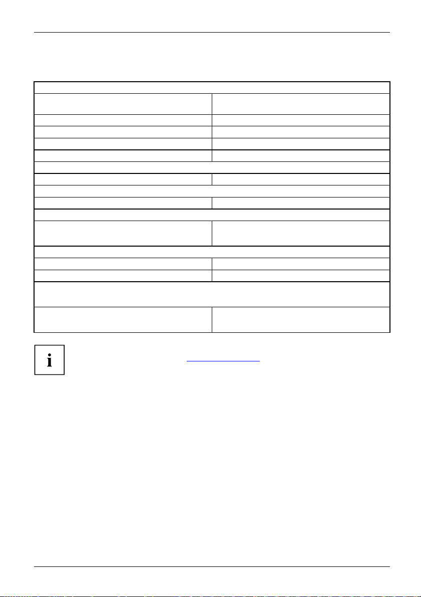
Electrical data
Safety standards complied with: IEC 60950, E N 60950, UL 60950 CSA 22.2
Protection class: I
Rated voltage range: 100 V – 240 V
Rated frequency:
Max. rated current: 2.5 A – 1.5 A
Dimensions
Width/depth/height: 328 mm/405 mm/105 mm
Weight
in basic configuration:
Environmental conditions
Environment class (3K2):
Environment class (2K2):
Temperature:
Operating (3K2): 15 °C .... 35 °C
Transportation (2K2): –25 °C .... 60 °C
The formation of condensation is not permitted while the device is in operation !
Clearance required to ensure adequate ventilation:
without air vents
with air vents
No.60950-1
50 Hz – 60 Hz
approx. 8 kg
DIN IEC 721 part 3-3
DIN IEC 721 part 3-2
min. 10 mm
min. 200 mm
The data sheet for this device provides further technical data. T he data s heet
can be found on our website "
Fujitsu Technology Solutions 53
http://ts.fujitsu.com".
Page 58

Index
Index
A
Alphanumeric keypad 23
Anti-theft protection 25
Audio input 17
Audio output 17
B
Base feet 14
Battery 52
BIOS Setup 25
BIOS Setup,
configuration 25
settings 25
system settings 25
Button,
ON/OFF switch 24
C
Cable,
connecting 16
disconnecting 16
Casing,
lead-sealing 25
CD-ROM drive
indicator 22
CD-ROM indicator 22
CE marking 8
Chain 25
Components
installing/removing 31
Connecting a PS/2 keyboard 18
Connecting,
keyboard 18
mouse 18
PS/2 keyboard 18
PS/2 mouse 18
USB keyboard 18
Contents of delivery 12
Cord
see Cable 16
Ctrl+Alt+Del 24
Cursor keys 23
D
Data p rotection 25
Device
indicators 21
Device drivers,
serial interface 18
Device,
anti-theft protection 25
lead-sealing 25
ports 17
setting up 13
switching off 21
switching on 21
transporting 7–8
upgrades 31
Devices,
connecting 18–19
Diskette driveMulti-card reader indicator
indicator 22
Disposal 8
Drive cage
installing 38
Drivers & Utilities DVD 8
DVD indicator 22
indicator 22
E
Electromagnetic compatibility 8
EMC, electromagnetic compatibility 41
Energy saving 8
Ergonomic
video workstation 13
External devices,
connecting 18–19
ports 17
F
Function keys 23
G
Getting started 12
H
Headphones 17
I
Important no tes 7
Indicators,
device 21
Installing,
software 19–20
switching on for the first time 19
Interfaces 17
54 Fujitsu Technology Solutions
Page 59

Index
K
Kensington Lock 25
Keyboard 23
Keyboard port 17
keyboard shortcuts 24
Keyboard shortcuts 24
Keyboard,
alphanumeric keypad 23
connecting 18
cursor keys 23
function keys 23
numeric keypad 23
port 18
Keys 24
Ctrl 24
Ctrl+Alt+Del 24
Keys,
Alt Gr 24
Control 24
Ctrl key 24
cursor keys 23
Enter 24
Enter key 24
menu key 24
Num Lock 24
Return 24
shift 24
shift key 24
Start key 24
L
LAN port 17
Lead-sealing 25
Line in 17
Line out 17
Lithium battery 51
Lithium battery,
replacing 52
Low voltage directive 8
Low-profile board 49
M
Main memory 51
Main memory,
upgrading 51
Mainboard
Upgrades 51
Mains adapter
connecting 15
Microphone port 17
Monitor
connecting 17
Monitor port 17
Monitor,
switching o ff 21
switching o n 21
Mouse port 17
Mouse,
connecting 18
N
Note
safety 7
Notes
CE marking 8
important 7
Numeric keypad 23
O
ON/OFF switch 24
Operating position, vertical 14
Overview
Device 5
P
Packaging 12
Packaging,
unpacking 12
Ports 10
Power-on indicator 22
flashes 22
lights green 22
lights oran ge 22
not lit 22
Preparing for first use, overview 12
Preparing for use,
overview 12
Processor 51
Processor, replacing 51
Property protection 25
PS/2 mouse port 17
PS/2 mouse,
connecting 18
port 18
R
Recycling 8
Removing
the drive carrier 37
Replacing,
lithium batter y 52
Replacing, lithium battery 52
Retransportation 7–8
Fujitsu Technology Solutions 55
Page 60

Index
S
Safety informatio n 7
Security measures 25
Serial interface 17–18
Serial interface,
connecting devices 18
settings 18
Servicing 31
Setup,
see BIOS Setup 25
Side cover 14
Software,
installing 19–20
System expansion 31
System settings,
BIOS Setup 25
System unit, see Device 8
T
Transportation 7–8
U
Universal Serial Bus 17
Upgrades
Mainboard 51
Upgrades,
device 31
USB devices,
connecting 19
USB port 18
USB port,
connecting devices 19
connecting keyboard 18
connecting the mouse 18
User Documentation DVD 8
V
Vertical operating position 14
Video workstation 13
56 Fujitsu Technology Solutions
 Loading...