

Page 1
Setup Guide (SAS model)
Read this Setup Guide first
Proceed to
next step
This guide describes the workow required to proceed from installation to
Read and understand the "Safety Precautions"
before use.
"Safet y Precautions"
Disk storage system
operation of the (SAS model).
Workow
Preparation
1
Installation
2
Cable Connection
3
Startup
4
P3AM-3102-04EN
Basic Setup
5
Monitoring Setup
6
Server Connection
7
Operation and Maintenance
8
The company names, product names and servic e names mentioned in this document are registered trademarks or trademarks of their respective companies.
The latest version of this document and the latest information about the ETERNUS DX60/DX80 is released in the following web-site. Access the following address if needed.
http://www.fujitsu.com/global/ser vices/computing/storage/eternus/products/diskstorage/dx- entr y/
S T E P
Preparation
Copyright 2010 FUJITSU LIMITED
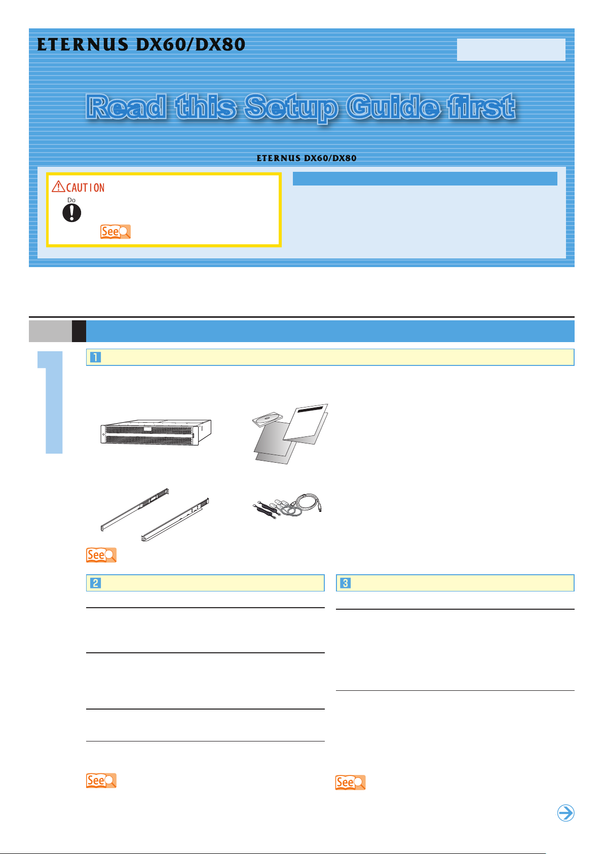
Package Contents Check
Refer to the "Package Contents" and check that there are no missing items.
ETERNUS DX60/DX80
Rack mount kit
"Packa ge Contents"
Misc. documents
Misc. cables
Prepare the following manuals:
n
Documentation CD
n
"Safety Precautions"
n
"Package Contents"
n
Other related manuals, for example, for a server or
networking equipment.
When ETERNUS SF Express is used, prepare the following
software and User's Guide:
n
ETERNUS SF Express Media Pack
n
"ETERNUS SF Express User's Guide"
Installation and Connection Preparation
Installation space
Check that the installation area meets the space requirements
of the rack in which the ETERNUS DX60/DX80 is to be installed.
Installation requirements
Check that the installation area satises all the requirements
described in the "Instructions for installation" section of the
"Safety Precautions".
Environmental conditions
Temperature: 5 – 40°C, Humidity: 20 – 80%RH
Power outlets
Check that a sufficient number of suitable wall outlets are
available.
n
"5.1 Installation Preparation" in the "User Guide"
n
"6.1 Connection Preparation" in the "User Guide"
n
"Safet y Precautions"
Setup Preparation
Completing and attaching the Network Settings label
Complete the following information in the Network Settings
label and attach it on the ETERNUS DX60/DX80.
n
IP address and subnet mask for the ETERNUS DX60/
DX80
n
IP address for maintenance work
Settings for the PC
n
Setup Network Environment
IP address: 192.168.1.2
Subnet mask: 255.255.255.0
n
Set the Web browser
Proxy server and Cache : Disable
Java Script, style sheets, and cookies : Enable
"7.1 Setup Preparation" in the "User Guide"
Page 2
(Front rack pillars)
(Rear rack pillars)
"R" is stamped on the inner
side of the right rack rail.
"L" is stamped on the inner
side of the left rack rail.
Loosen the screws,
and adjust the rack rails to
the depth of the rack.
[Left]
[Right]
S T E P
ETERNUS DX60/DX80
1st position
(M5 screws)
3rd position
(M5 screws)
1st position
(M5 screws)
3rd position
(M5 screws)
2U
[Screw location of the rack rail (bracket)]
Tighten the screws in the same locations on both the front and rear sides of the rack pillars
[Left] [Right]
Rack rail (bracket)
Base line of the
ETERNUS DX60/DX80
Between the EXP#0 and
EXP#1 expanders at the rear
of the drive enclosure
DE_No. label
At the right side of the front of
the drive enclosure
Controller
Enclosure
Controller
Enclosure
Drive
Enclosure
Controller
Enclosure
Drive
Enclosure
Drive
Enclosure
Controller
Enclosure
Underside of
the SAS (OUT) side plug
Underside of
the SAS (IN) side plug
Installation
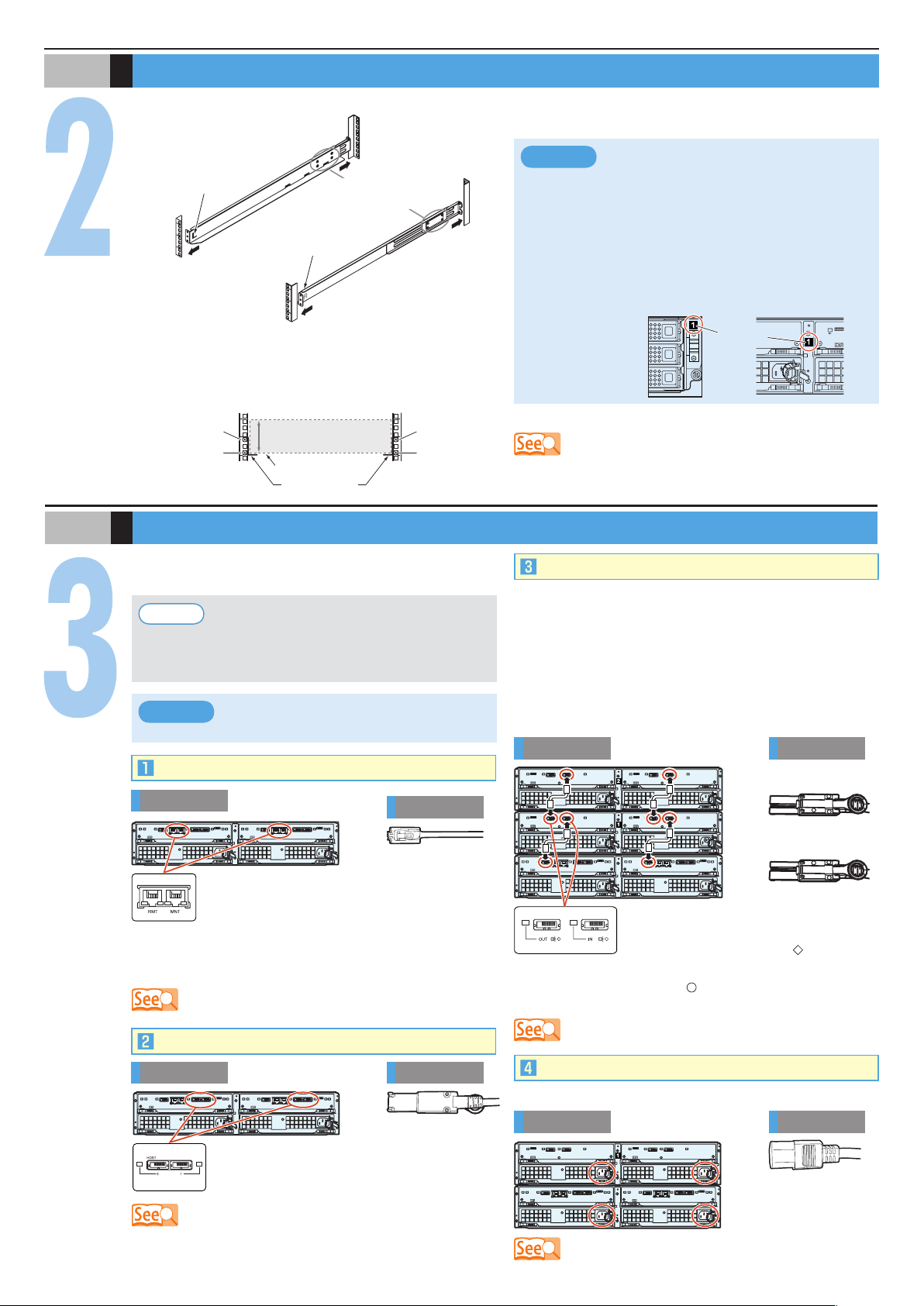
The rack rail (bracket) needs to be attached to the rack and the ETERNUS DX60/DX80 mounted.
Adjust the rack rail (bracket)
1.
size to t the rack.
Attach the rack rails (brackets) to the rack. The size of the
2.
ETERNUS DX60/DX80 is 2U.
Mount the ETERNUS DX60/DX80 in the rack.3.
Make sure to install or remove the enclosure
IMPORTANT
●
to or from the rack by two or more people.
Multiple Drive Enclosures must be connected
●
to the controller enclosure following the order
of the "DE_No. label" numbers attached to
each Drive Enclosure. The position of the
labels are in the positions shown below.
Fasten the ETERNUS DX60/DX80 to the rack.4.
"5.2 Rack Installation" in the "User Guide"
S T E P
Cable Connection
Various cabl es need to be connect ed to the rear of th e
ETERNUS DX60/DX80.
Point
IMPORTANT
LAN Cables
Rear view
RMT port on ly needs to be co nnected when the remote
suppor t connection is to be independent of the customer
network.
MiniSAS Cables (for Host Interface)
To he lp wit h ca bl e manag ement and p revent
incorrect connection, attach labels to the cables
an d make a not e o f c onn e cti o n o rigi ns and
destinations.
The c ables sho ul d never be bent, twisted or
pulled.
Cable
The RMT port is on the left side, and MNT port
is on the right side.
The MNT port must always be connected. The
"6.2 L AN Cable Connection (for Operation Management)" in t he "User
Guide"
MiniSAS Cables (for Drive Enclosures)
When Drive Enclosures are installed, miniSAS cables are
used to connect between the SAS ports of the enclosures.
Connect the Controller Enclosure to Drive Enclosure 1, Drive
Enclosure 1 to Drive Enclosure 2, Drive Enclosure 2 to Drive
Enclosure 3, etc. The number of Drive Enclosure can be
checked with the "DE_No." label.
Example for connection of miniSAS cable
(when two Drive Enclosures are installed)
Rear view
The SAS (OUT) port is on the left side, and
SAS (IN) port is on the right side.
Insert the connector with a mark on its
underside in the SAS (OUT) port.
Insert the connector with a mark on its underside in the
SAS (IN) port.
"6.6 MiniSAS Cable Conn ection (For Drive Enclosures)" in the " User
Guide"
Cable
Rear view
For each CM, the port numbers are (left to right)
0 and 1. Connect a miniSAS cable to each of
these ports.
"6.5 MiniSAS Cable Connection (For SAS)" in the "User Guide"
Cable
Power Cords
Use release ties to hold the power cords in place.
Rear view
"6.7 Power C ord Connection" in the " User Gui de"
Cord
Page 3

S T E P
Controller
Enclosure
Power switch
Startup
Connect the PC to the ETERNUS DX60/DX80 with a LAN cable (for operation management), and turn on the ETERNUS DX60/
DX80.
n
"7.1 Setup Preparation" in the "User Guide"
n
"7.2 Basic Setup" in the "U ser Guide"
S T E P
IMPORTANT
The first time the power is turned on, volume
for mattin g may st ar t ac cording to the factor y
default settings. This does not affect the setup
operation, which may be started immediately.
Basic Setup
Basic ETERNUS DX60/DX80 setup is performed by accessing
the "Initial Setup" and "Conguration Wizard" functions with a
Web browser.
Start the Web browser on the PC and enter either of the
1.
following URLs in the address bar of the Web browser.
http://192.168.1.1/
https://192.168.1.1/
Enter the following user name and password, and click the
2.
[Logon] button to logon to the ETERNUS DX60/DX80.
User name: root
Password: root (Default)
After logging on, the Storage System Status screen
3.
appears.
Point
Initial Setup
When ETERNUS SF Express is used, per form
the fo l l o w i n g set u p , and th e n refer to the
"ETERNUS SF Express User's Guide" to install
the ETERNUS DX Disk storage system.
Initial Setup
Set Date and Time
●
Set Storage System Name
●
Change Password
●
Setup Network Environment
●
After completing these settings with the Finish step, close
the web browser to end the setup session, then detach the
direct connection LAN cable (for operation management)
from the PC and connect it to the normal network. Then
try logging on again via the normal network, using the IP
address that has just been set.
"7.2.1 Initial Setup" in the "User Guide"
Configuration Wizard
Perform the necessary settings to operate the ETERNUS
DX60/DX80 using the Conguration Wizard.
The [Configuration Wizard] screen appears by clicking the
[Conguration Wizard] button on the [Easy Setup] tab.
n
Create RAID Group
n
Create Volume
n
Dene Host
"7.2.2 Con gurat ion Wizard" in the "User G uide"
n
Congure Afnity Group
n
Dene LUN Mapping
Set the necessary environment for operating the ETERNUS
DX60/DX80 with its initial setup.
The [Initial Setup] screen appears by clicking the [Initial
Setup] menu on the [Easy Setup] tab.
This screen is used to set the following items:
n
Set Date and Time
n
Set Storage System Name
n
Change Password
n
Set SAS Port Parameters
n
Setup Network Environment
Point
De f aul t R A ID grou p s, vol u mes and affin i t y
groups are preset in the factor y. Refer to " Web
GUI User Guide" if the preset values are to be
changed.
Assigning Hot Spares
Register hot spares for use in case the regular disks fail.
The [Assign Hot Spare] screen appears by clicking [Assign
Hot Spare] under the [RAID Group Management] menu on the
[Volume Settings] tab.
"7.2.3 Hot Spare Registratio n" in the "User Guide"
Point
Check the facto ry set tings and regi ster a hot
spare as required.
Page 4

S T E P
Monitoring Setup
Perform the ETERNUS DX60/DX80 monitoring setup if required.
n
Notication of ETERNUS DX60/DX80 problems as they occur is possible if the event notication method and level have
been set.
n
For e-mail notication of ETERNUS DX60/DX80 problems, a destination e-mail address must be set.
n
If "ServerView" is used to monitor the server, the ETERNUS DX60/DX80 must be set to send an SNMP Trap to the server.
n
If remote suppor t is required, the ETERNUS DX60/DX80 must be set to notify the remote support center of failures.
S T E P
S T E P
Point
Remote support allows prompt detection and resolution of trouble.
"7.4 Monitoring Setup" in the "Us er Guide"
Server Connection
Various tasks need to be performed before the ETERNUS DX60/DX80 can be connected to the server. These include the
installation of the appropriate drivers.
Check which server OS, and/or SAS card are to be connected to before starting this step.
For details on the setting, refer to "ETERNUS DX Disk storage systems Server Connection Guide (SAS)"(*).
* : Download from the specied web-site in the Documentation CD.
n
"7.5 Server Connect ion Setup" in the "U ser Guid e"
n
"ETER NUS DX Disk storage systems Se rver Connection Guide (SAS)"
-
for Windows® - for Linux
-
for Solaris™ Operating System - ETERNUS DX Disk Sto rage System Settings for ETERN US DX60/ DX80
-
for VMwa re® ESX
All necessary settings are complete, and the ETERNUS DX60/DX80 is now ready for normal operation.
Operation and Maintenance
Status check
The status of the ETERNUS DX60/DX80 should be regularly monitored by checking the LEDs and using the Web browser.
Data backup
Important data should be regularly backed up to a tape drive or similar device as a precaution against system failures.
Maintenance support period
The maintenance support period for the ETERNUS DX60/DX80 is 5 years from the date of purchase.
This manual uses recycled paper.
ETERNUS DX60/DX80 Disk storage system Setup Guide
Issuanc e respo nsibility: FUJ ITSU LIM ITED
The contents of this manual may b e updated without notice.
W hile the co ntents of this manual are the product of all due care a nd
diligence, no res ponsibility can be accepted for op erati onal problems
ari si ng from any er ro rs or miss ing in fo rm ation , or o th er use of t he
information containe d in this manual.
Fujit su assume s no liability for damage s to third pa rt y copyr ights or
other rights ari sing from the use of any inform ation in t his manua l.
C ontents of this manual are no t to be reprodu ced without permissi on
from Fujit su.
Manuals with missing or wrongl y collated pages will be replaced fre e of
charge.
(SAS model)
P3AM -3102-04EN
Date of issuance: July 2010
Printed in Japan
 Loading...