

Page 1
Page 2

Page 3

This guide provides a variety of basic information about Web GUI for the ETERNUS DX60/DX80.
It should be referred to when setting up and maintaining the ETERNUS DX60/DX80.
This guide is specially written for ETERNUS DX60/DX80 Web GUI system administrators and
operators. Knowledge of UNIX or Windows® systems is required.
Structure of This Manual
This manual consists of the following 8 chapters and an Appendix.
● Chapter 1 Outline
This chapter describes the outlines, features, operation environment, and operating topology
for GUI.
Preface
Second Edition
October 2009
● Chapter 2 Startup and Shutdown
This chapter describes how to start, exit, log on and log off from GUI, and information about
operation screens.
● Chapter 3 Initial Setup
This chapter describes the Initial Setup menu.
● Chapter 4 Status Menu
This chapter describes the status display menu for the device.
● Chapter 5 Configuration
This chapter describes the configuration related menu.
Details for Configuration Wizard, RAID group management, volume management, and
Advanced Copy management
are provided.
● Chapter 6 Global Settings
This chapter describes the user management, network settings, remote support settings,
system settings
, and Host I/F (host interface) management.
● Chapter 7 Maintenance
This chapter describes the hardware maintenance procedures.
P2X0-0700-02ENZ0
● Chapter 8 Display and Download Information (Diagnosis)
This chapter describes how to display and download ETERNUS DX60/DX80 related
information.
ETERNUS DX60/DX80 Web GUI User Guide
3
Copyright 2009 FUJITSU LIMITED
Page 4
Preface
Procedures to install the site certificate of the Web site are provided for the Appendix.
Latest Information
The information in this document is subject to change without notice for functionality expansion
of ETERNUS DX60/DX80 and improvement. The latest version of this document and the latest
information about the ETERNUS DX60/DX80 is released in the following web-site. Access the
following address if needed.
http://www.fujitsu.com/global/services/computing/storage/eternus/products/diskstorage/dx60dx80/
Related Materials
Other manuals for the ETERNUS DX60/DX80 are as follows:
• ETERNUS DX60/DX80 Disk storage systems User Guide
• ETERNUS DX60/DX80 Command Line Interface (CLI) User's Guide
• ETERNUS Disk storage systems Server Connection Guide (Fibre Channel) (*1)
• ETERNUS Disk storage systems Server Connection Guide (iSCSI) (*1)
• ETERNUS Disk storage systems Server Connection Guide (SAS) (*1)
*1: Download the required manuals for your device environment (server OS and Fibre Channel card type,
etc.) from the specified web site. Refer to the Document CD provided with the ETERNUS DX60/DX80
for URLs of the manual download site.
Acknowledgments
• Microsoft, Windows, and Windows Server are either registered trademarks or trademarks of
Microsoft Corporation in the United States and other countries.
• UNIX is a registered trademark of The Open Group in the United States and other countries.
• Sun, Sun Microsystems, Sun logo, Solaris, and all Solaris-related trademarks and logos are
trademarks and registered trademarks of Sun Microsystems, Inc. in the United States and
other countries and are used under license from Sun Microsystems Inc.
• AIX is a trademark of IBM Corp.
• Linux is a registered trademark or trademark of Linus Torvalds in the United States and other
countries.
• Red Hat, RPM, and all Red Hat-based trademarks and logos are trademarks or registered
trademarks of Red Hat, Inc. in the United States and other countries.
• HP-UX is a trademark of Hewlett-Packard in the U.S. and other countries.
• Other company names, product names, and service names are registered trademarks or
trademarks of their respective owners.
P2X0-0700-02ENZ0
ETERNUS DX60/DX80 Web GUI User Guide
4
Copyright 2009 FUJITSU LIMITED
Page 5

Preface
Abbreviations
The following products will be represented throughout this manual by the following abbreviations.
• Microsoft® Windows® 2000 Server operating system and Microsoft® Windows® 2000
Advanced Server operating system are abbreviated as Windows® 2000.
• Microsoft® Windows Server® 2003, Standard Edition, and Microsoft® Windows Server®
2003, Enterprise Edition are abbreviated as Windows Server® 2003.
• Microsoft® Windows Server® 2008, Standard Edition, and Microsoft® Windows Server®
2008, Enterprise Edition are abbreviated as Windows Server® 2008.
• Windows® Server refers to both the Windows Server® 2003 and Windows Server® 2008.
• Windows® refers to all the Windows products listed here: Windows® 2000, Windows Server®
2003, and Windows Server® 2008.
• Solaris™ Operating System is abbreviated as Solaris OS.
P2X0-0700-02ENZ0
Screen shot(s) reprinted with permission from Microsoft Corporation.
Copyright 2009 FUJITSU LIMITED
ETERNUS DX60/DX80 Web GUI User Guide
5
Copyright 2009 FUJITSU LIMITED
Page 6

Contents
Chapter 1 Outline .......................................................................................9
1.1 Outline ................................................................................................................ 9
1.2 Features ........................................................................................................... 10
1.3 Operating Environment .................................................................................... 11
1.4 Operating Topology .......................................................................................... 12
Chapter 2 Startup and Shutdown ...........................................................13
2.1 Startup .............................................................................................................. 13
2.2 Logon ............................................................................................................... 15
2.3 Logoff ............................................................................................................... 17
2.4 Exit ................................................................................................................... 18
2.5 Operation Screens ........................................................................................... 19
2.5.1 Screen structures ...................................................................................................................... 19
2.5.2 User Role ................................................................................................................................... 20
Chapter 3 Initial Setup .............................................................................25
Chapter 4 Status Menu ............................................................................33
4.1 Storage System Status .................................................................................... 33
4.1.1 Storage System ......................................................................................................................... 36
4.1.2 Controller Enclosure .................................................................................................................. 37
4.1.3 Drive Enclosure ......................................................................................................................... 42
4.2 RAID Group Status .......................................................................................... 45
4.3 Volume Status .................................................................................................. 47
4.4 Advanced Copy Status ..................................................................................... 49
Chapter 5 Configuration..........................................................................50
5.1 Configuration Wizard ........................................................................................ 50
5.2 RAID Group Management ................................................................................ 69
5.2.1 Create RAID Group ................................................................................................................... 69
5.2.2 Delete RAID Group .................................................................................................................... 74
5.2.3 Assign Hot Spare ....................................................................................................................... 75
5.2.4 Release Hot Spare .................................................................................................................... 78
5.2.5 Logical Device Expansion ......................................................................................................... 80
5.2.6 Set RAID Group Name .............................................................................................................. 82
5.2.7 Set Eco-mode Schedule ............................................................................................................ 83
5.2.8 Change CM Ownership ............................................................................................................. 91
P2X0-0700-02ENZ0
ETERNUS DX60/DX80 Web GUI User Guide
6
Copyright 2009 FUJITSU LIMITED
Page 7

Contents
5.3 Volume Management ....................................................................................... 93
5.3.1 Create Volume ........................................................................................................................... 93
5.3.2 Delete Volume ........................................................................................................................... 96
5.3.3 Format Volume .......................................................................................................................... 97
5.3.4 Encrypt Volume ......................................................................................................................... 99
5.3.5 LUN Concatenation ................................................................................................................. 101
5.3.6 RAID Migration ........................................................................................................................ 103
5.3.7 Initialize Snap Data Volume .................................................................................................... 107
5.3.8 Release Reservation ............................................................................................................... 109
5.3.9 Set Volume Name ................................................................................................................... 111
5.3.10 Configure LUN Mapping .......................................................................................................... 112
5.4 Advanced Copy Management ........................................................................ 119
5.4.1 Setup Snap Data Pool ............................................................................................................. 124
5.4.2 Manage Copy Session ............................................................................................................ 129
5.4.3 Register Copy License ............................................................................................................ 131
5.4.4 Modify Copy Parameters ......................................................................................................... 132
5.4.5 Modify EC/OPC Priority ........................................................................................................... 134
5.4.6 Modify Copy Table Size ........................................................................................................... 135
Chapter 6 Global Settings .....................................................................140
6.1 User Management .......................................................................................... 140
6.1.1 Setup User Account ................................................................................................................. 141
6.1.2 Change User Password ........................................................................................................... 144
6.1.3 Initialize User Account ............................................................................................................. 145
6.2 Network Settings ............................................................................................ 147
6.2.1 Setup Network Environment .................................................................................................... 147
6.2.2 Setup SNMP Agent ................................................................................................................. 150
6.2.3 Download MIB File .................................................................................................................. 154
6.2.4 Perform SNMP Trap Test ........................................................................................................ 155
6.2.5 Setup E-Mail Notification ......................................................................................................... 156
6.2.6 Display SMTP Log ................................................................................................................... 159
6.2.7 Setup Event Notification .......................................................................................................... 160
6.2.8 Renew SSL Certificate ............................................................................................................ 164
6.3 Remote Support ............................................................................................. 165
6.3.1 Display Support Information .................................................................................................... 165
6.3.2 Display Communication Log .................................................................................................... 166
6.3.3 Setup Remote Support ............................................................................................................ 167
6.3.4 Update Customer Information ................................................................................................. 176
6.3.5 Update Communication Environment Information ................................................................... 177
6.3.6 Setup Log Sending Parameters ..............................................................................................180
6.3.7 Stop/Restart Remote Support ................................................................................................. 182
6.4 System Settings ............................................................................................. 184
6.4.1 Modify Date and Time ............................................................................................................. 184
6.4.2 Modify Storage System Name ................................................................................................. 186
6.4.3 Setup Encryption Mode ........................................................................................................... 187
P2X0-0700-02ENZ0
ETERNUS DX60/DX80 Web GUI User Guide
7
Copyright 2009 FUJITSU LIMITED
Page 8

Contents
6.4.4 Change Box ID ........................................................................................................................ 189
6.4.5 Setup Power Management ...................................................................................................... 190
6.5 Host I/F Management .................................................................................... 193
6.5.1 Set Port Parameters ................................................................................................................ 195
6.5.2 Setup Host ............................................................................................................................... 202
6.5.3 Setup Host Response .............................................................................................................. 212
6.5.4 Modify Reset Group ................................................................................................................. 217
Chapter 7 Maintenance..........................................................................219
7.1 Hot Expansion ................................................................................................ 219
7.1.1 Add Drive Enclosure ................................................................................................................ 220
Chapter 8 Display and Download Information (Diagnosis)................223
8.1 Display Event Log .......................................................................................... 223
8.2 Export/Delete Log .......................................................................................... 225
8.3 Export Panic Dump ........................................................................................ 228
8.4 Start/Stop Performance Monitoring ................................................................ 231
8.5 Display Performance Information ................................................................... 233
8.6 Display Error Information ............................................................................... 234
Appendix A Install Site Certificate...........................................................236
A.1 For Internet Explorer ....................................................................................... 236
A.2 For Firefox....................................................................................................... 241
Index .......................................................................................................244
P2X0-0700-02ENZ0
ETERNUS DX60/DX80 Web GUI User Guide
8
Copyright 2009 FUJITSU LIMITED
Page 9
Chapter 1 Outline
This chapter describes the outlines, features, operating environment, and operating topology for
ETERNUS DX60/DX80 Web GUI (hereinafter referred to as "GUI").
GUI is installed in controllers of the ETERNUS DX60/DX80 (hereinafter also referred to as "the
device"), and used for performing settings and maintenance via web browser.
1.1 Outline
Use GUI to set the operating environment and check status for the ETERNUS DX60/DX80.
GUI can be operated from a web browser by connecting the PC via a LAN connection.
Operation
Server
LAN
*1
ETERNUS DX60/DX80
Management Server
Mail Server Program
*1: Connect the operation server and the ETERNUS DX60/DX80
with a Fibre Channel (FC), iSCSI, or SAS cable.
PC
Web Browser
Refer to "2.1 Startup" (page 13) for details of GUI start up.
Web GUI
Operating via
web browser
P2X0-0700-02ENZ0
ETERNUS DX60/DX80 Web GUI User Guide
9
Copyright 2009 FUJITSU LIMITED
Page 10

Chapter 1 Outline > 1.2 Features
1.2 Features
The features for GUI are as follows:
● Initial and basic settings by the wizard
● System status
● Disk configuration check function
● Checking the extent of a failure
The wizard enables you to set the minimum requirement to run the ETERNUS DX60/DX80 by
following the instructions on the wizard screen.
This function displays the device installation image.
This function displays a list of disk drives. It is also possible to display the number of
constructible RAID groups by specifying the RAID group configuration requirements.
If a disk drive failure occurs, "Host Port", "Affinity Group", "Volume", "RAID group", and
"installation location" can be referenced to determine the extent of the failure.
● Easy operation
If a hardware failure is detected, the system administrator can receive a mail containing
detected failure information.
P2X0-0700-02ENZ0
ETERNUS DX60/DX80 Web GUI User Guide
10
Copyright 2009 FUJITSU LIMITED
Page 11
Chapter 1 Outline > 1.3 Operating Environment
1.3 Operating Environment
The following server or PC environment is required for the use of GUI.
Confirmed operating environment Version
Browsers Microsoft® Internet Explorer 6.0 or 7.0
Mozilla Firefox™ 3.0.x
Image resolution 1024 x 768 or more -
• Set the web browser not to use a proxy server and cache (Temporary
Internet Files).
• Browsers require the following operating environment. Enable the
following functions for each browser.
- JavaScript and Style Sheet
- Cookie
P2X0-0700-02ENZ0
ETERNUS DX60/DX80 Web GUI User Guide
11
Copyright 2009 FUJITSU LIMITED
Page 12
Chapter 1 Outline > 1.4 Operating Topology
1.4 Operating Topology
GUI can be operated by a PC or workstation with a web browser installed, that is connected via a
LAN.
Two connection topologies are allowed:
• Direct connection of the PC to the device
• Network connection via an existing LAN
The operating topology diagram below shows a direct connection with a LAN cable.
ETERNUS DX60/DX80
*1
*1: Connect the setting PC and the ETERNUS DX60/DX80 with a LAN cable.
Either a straight through or crossover LAN cable can be used.
Set by direct
connection
Setting PC
The operating topology diagram below shows operation on an existing network.
Setting PC
Set via network
Operation server
PC
LAN
ETERNUS DX60/DX80
P2X0-0700-02ENZ0
*2
*2: Connects the operation server and the ETERNUS DX60/DX80 using a Fibre Channel (FC), iSCSI, or SAS cable.
ETERNUS DX60/DX80 Web GUI User Guide
12
Copyright 2009 FUJITSU LIMITED
Page 13
Chapter 2 Startup and Shutdown
This chapter describes how to start, exit, log on and log off from GUI, and information about
operation screens.
2.1 Startup
Startup the logon screen for GUI.
Connect the PC and the ETERNUS DX60/DX80 using a LAN cable, and display the logon
screen via the web browser.
The procedure to start up the logon screen for GUI is as follows:
Procedure
1 Directly connect the PC and MNT port of the ETERNUS DX60/DX80 via LAN
cable.
2 Set the IP address and subnet mask for the PC to match the ETERNUS DX60/
DX80 network settings.
3 Enter the URL to the address bar in the web browser.
Specify "http://IP address of the device/" or "https://IP address of the device" (Default IP
address is "192.168.1.1").
→ The logon screen for GUI is displayed. Refer to "2.2 Logon" (page 15) for detailed
procedure to logon.
P2X0-0700-02ENZ0
ETERNUS DX60/DX80 Web GUI User Guide
13
Copyright 2009 FUJITSU LIMITED
Page 14
Chapter 2 Startup and Shutdown
> 2.1 Startup
The confirmation screens for site certificate may be displayed when
using SSL (https) to start up GUI (the display contents vary
according to your web browser).
However, this should not cause any problems. Accept the site
certificate and continue the process.
The following shows an example when using Internet Explorer 7.
There is a problem with this website's security certificate. The
security certificate presented by this website was not issued by
a trusted certificate authority.
Security certificate problems may indicate an attempt to fool you
or intercept data you send to the server.
We recommend that you close this webpage and do not con-
tinue to this Web site.
This warning will not be displayed after installing the site information.
Refer to "Appendix A Install Site Certificate" (page 236)
procedure to install the site certificate to the your web browser.
f or
• Refer to "6.2.1 Setup Network Environment" (page 147) for
procedure to set the IP address of the MNT port.
• The following ports should be used for http and https connections:
Protocol Port to be used (Default)
http 80
https 443
End of procedure
P2X0-0700-02ENZ0
ETERNUS DX60/DX80 Web GUI User Guide
14
Copyright 2009 FUJITSU LIMITED
Page 15
Chapter 2 Startup and Shutdown > 2.2 Logon
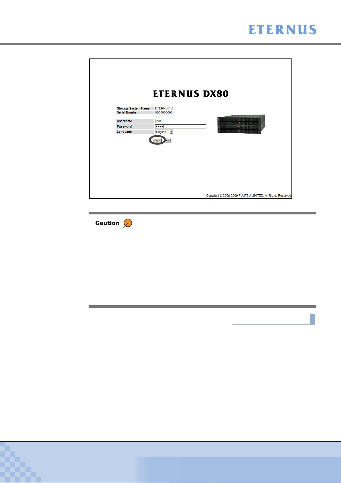
2.2 Logon
Log on to GUI to start the operation. The GUI operation screen appears.
The menu displayed pertains to the logged on user role. An Advanced privilege user (CE) can
access various maintenance/settings menus, a Standard user (SE) has operational access, and
a Monitor user (general user) can access the status display menus.
The procedure for logging on is as follows:
Procedure
The following will cause an error. If this occurs, note the error message and
try re-logging on after completing the process.
• Attempting to logon while four users are already logged on.
• Attempting to logon while another application is already logged on.
1 Select the language (English or Japanese) from the logon screen.
2 Enter the Username and Password, and click the [Logon] button.
The Username and the Password vary depending on which account is being used to
logon.
• Username
root
• Password
root (Default)
• Refer to "6.1 User Management" (page 140) for user accounts.
• If the input error occurs, enter the Username and Password again
to log on to the ETERNUS DX60/DX80.
P2X0-0700-02ENZ0
ETERNUS DX60/DX80 Web GUI User Guide
15
Copyright 2009 FUJITSU LIMITED
Page 16
Chapter 2 Startup and Shutdown
> 2.2 Logon
→ The operation screen appears.
Up to four users can be logged on concurrently. Logging on five or
more users is not allowed.
Also note that a warning message appears in the following condi-
tions and some functions cannot be used. Confirm the current GUI
usage state and start operation.
• When attempting to logon, another user is already logged on and
performing one of the following operations.
- Applying controller firmware
- Applying disk firmware
- RAID group diagnosis
- Disk diagnosis
End of procedure
P2X0-0700-02ENZ0
ETERNUS DX60/DX80 Web GUI User Guide
16
Copyright 2009 FUJITSU LIMITED
Page 17
Chapter 2 Startup and Shutdown > 2.3 Logoff
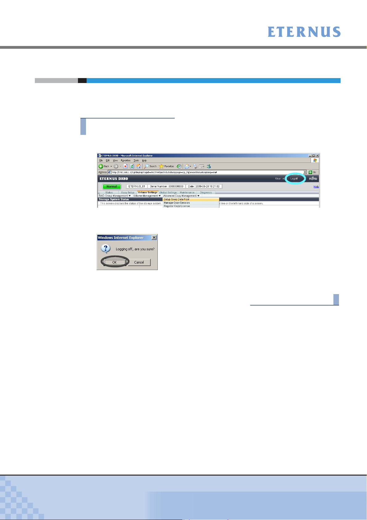
2.3 Logoff
Log off from GUI to finish the operation.
The procedure for logging off is as follows:
Procedure
1 Click the [Logoff] link on the top right of the screen.
→ A confirmation screen appears.
2 Click the [OK] button.
→ This completes the logging off process.
The logon screen appears.
End of procedure
P2X0-0700-02ENZ0
ETERNUS DX60/DX80 Web GUI User Guide
17
Copyright 2009 FUJITSU LIMITED
Page 18
Chapter 2 Startup and Shutdown > 2.4 Exit
2.4 Exit
Exit from GUI.
The procedure to exit is as follows:
Procedure
1 Click the [Close] button for the web browser.
→ Exit from GUI.
Make sure to perform "2.3 Logoff" (page 17) operation before exiting GUI.
If exiting GUI without logging off, the logon status is not released.
The logon screen does not appear.
End of procedure
P2X0-0700-02ENZ0
ETERNUS DX60/DX80 Web GUI User Guide
18
Copyright 2009 FUJITSU LIMITED
Page 19
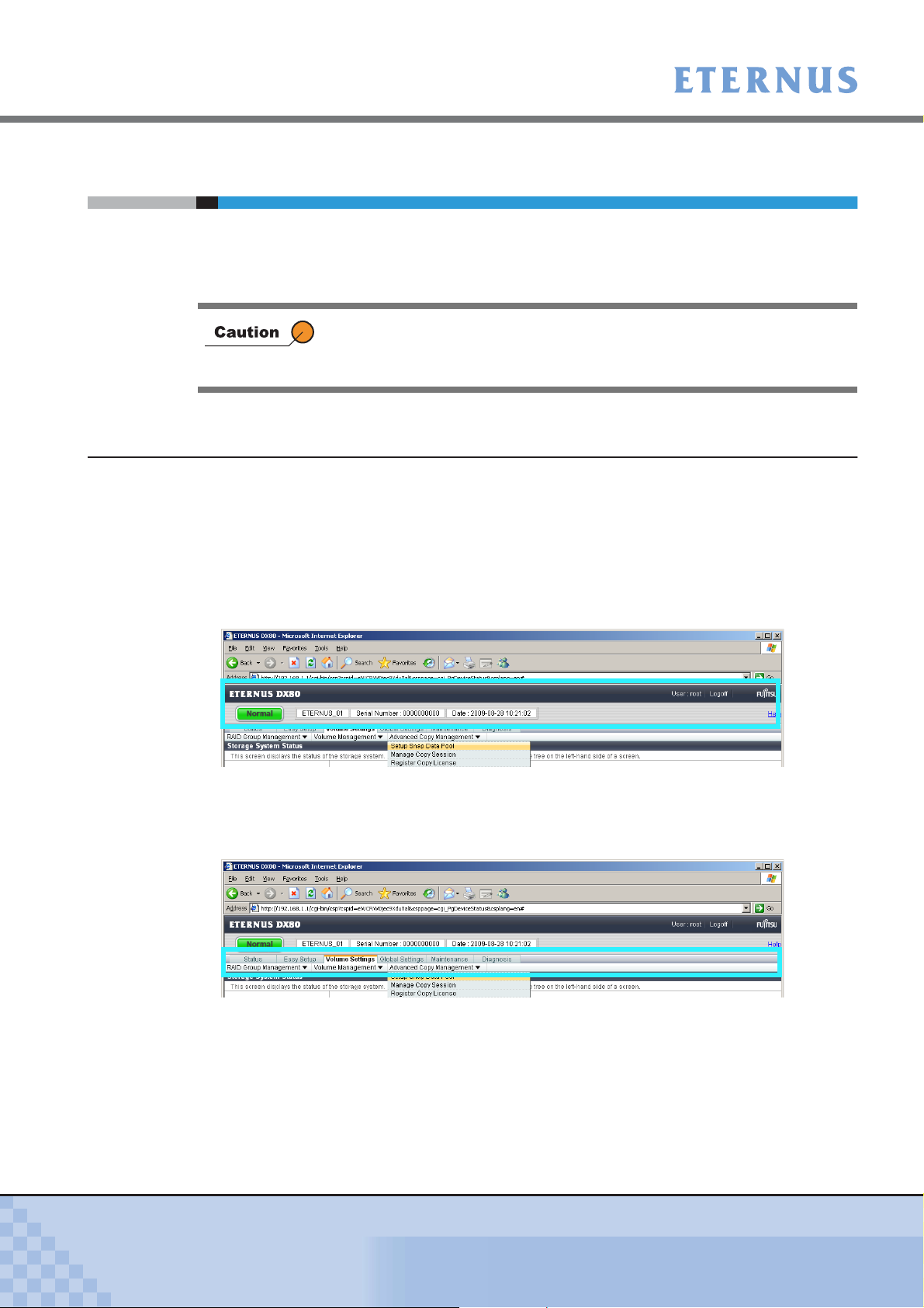
Chapter 2 Startup and Shutdown > 2.5 Operation Screens
2.5 Operation Screens
This section provides a description about GUI operation screens.
Click the [Help] link or [Help] button for a detailed explanation of the functions used during opera-
tion. An explanation (help) screen of the function is displayed.
2.5.1 Screen structures
The following shows the main contents that configure the operation screen. They are always dis-
played.
• Be sure to log off after all necessary operations are completed.
• If the operation screen is not updated when accessing the GUI, close
the web browser, and log on again.
● Global Header
ETERNUS DX60 or ETERNUS DX80 logo, [Logoff] and [Help] links, general status, device
serial number, and date and time are displayed in the Global Header.
General status of ETERNUS DX60/DX80 is displayed as an image with character strings.
● Menu Bar
Clicking the tabs in the menu bar displays sub menus related to the selected function.
Clicking the sub menu with the "!" symbol displays pull-down menu options.
P2X0-0700-02ENZ0
ETERNUS DX60/DX80 Web GUI User Guide
19
Copyright 2009 FUJITSU LIMITED
Page 20
Chapter 2 Startup and Shutdown
> 2.5 Operation Screens
● Title Bar
The current function name is displayed.
2.5.2 User Role
The available menus for GUI will differ according to the account type.
The following table shows the difference between user roles.
User role Available functions Default account
Advanced "Advanced" is a maintenance engineer privilege.
Standard "Standard" is a system administrator privilege.
Monitor "Monitor" is a general user privilege.
f.ce
Setting maintenance such as status display, configuration
management, and maintenance functions are available.
root
Functions such as status display and configuration
management are available.
None
Only the status display function is available.
● Settings and functions for an Advanced privilege user
• Initial Setup
• Status
• Volume Settings
• Global Settings
• Maintenance
• Diagnosis
• Utilities
● Settings and functions for a Standard privilege user
• Initial Setup
• Status
• Volume Settings
• Global Settings
• Maintenance (Add Drive Enclosures)
• Diagnosis
● Settings and functions for a Monitor privilege user
• Status
• Diagnosis (Display Event Log and Display Performance Information)
P2X0-0700-02ENZ0
ETERNUS DX60/DX80 Web GUI User Guide
20
Copyright 2009 FUJITSU LIMITED
Page 21
Chapter 2 Startup and Shutdown
> 2.5 Operation Screens
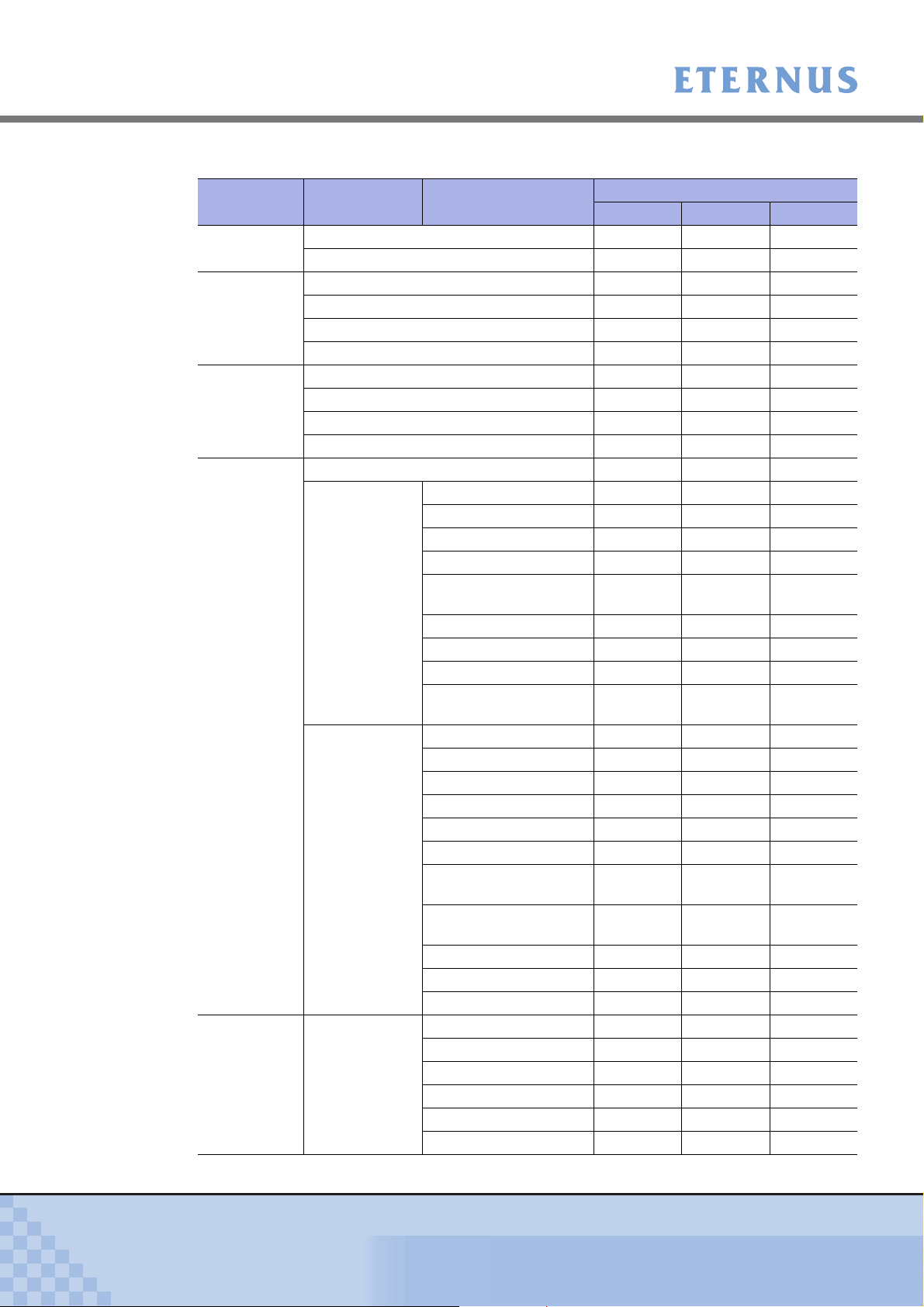
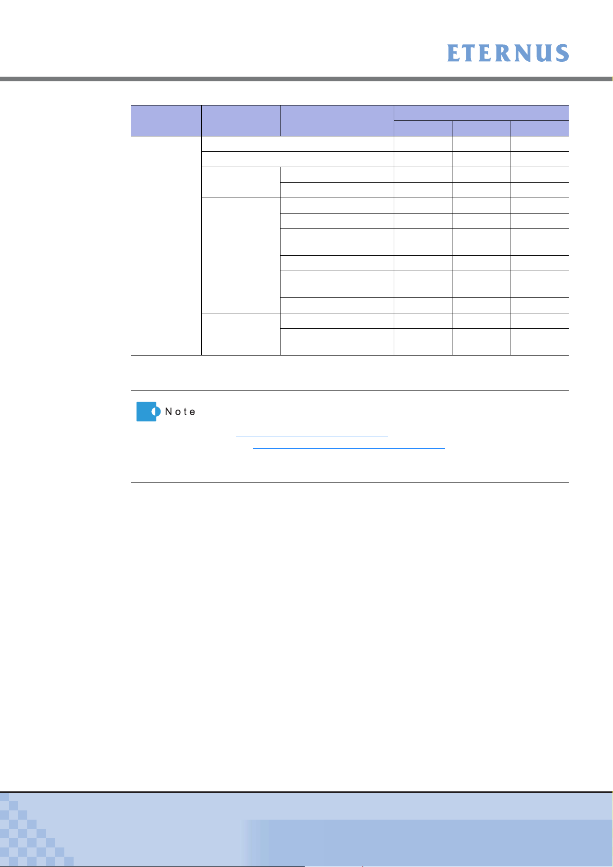
The following table shows the availability of functions for each user role.
Chapter Category Function
Startup and
Shutdown
Initial Setup Set Date and Time − OK OK
Status Menu Storage System Status OK OK OK
Configuration Configuration Wizard − OK OK
Configuration Advanced Copy
User Role
Monitor Standard Advanced
Logon OK OK OK
Logoff OK OK OK
Set Storage System Name − OK OK
Change Password − OK OK
Setup Network Environment − OK OK
RAID Group Status OK OK OK
Volume Status OK OK OK
Advanced Copy Status OK OK OK
RAID Group
Management
Volume
Management
Management
Create RAID Group − OK OK
Delete RAID Group − OK OK
Assign Hot Spare − OK OK
Release Hot Spare − OK OK
Logical Device
Expansion
Set RAID Group Name − OK OK
Set Eco-mode Schedule − OK OK
Change CM Ownership − OK OK
Modify RAID Group
Parameters
Create Volume − OK OK
Delete Volume − OK OK
Format Volume − OK OK
Encrypt Volume − OK OK
LUN Concatenation − OK OK
RAID Migration − OK OK
Initialize Snap Data
Volume
Modify Cache
Parameters
Release Reservation − OK OK
Set Volume Name − OK OK
Configure LUN Mapping − OK OK
Setup Snap Data Pool − OK OK
Manage Copy Session − OK OK
Register Copy License − OK OK
Modify Copy Parameters − OK OK
Modify EC/OPC Priority − OK OK
Modify Copy Table Size − OK OK
− OK OK
−−OK
− OK OK
−−OK
P2X0-0700-02ENZ0
ETERNUS DX60/DX80 Web GUI User Guide
21
Copyright 2009 FUJITSU LIMITED
Page 22
Chapter 2 Startup and Shutdown
> 2.5 Operation Screens
Chapter Category Function
Global
Settings
User
Management
Network
Settings
Remote
Support
Setup User Account − OK OK
Change User Password − OK OK
Initialize User Account − OK OK
Setup Network
Environment
Setup SNMP Agent − OK OK
Download MIB File − OK OK
Perform SNMP Trap
Te st
Setup E-Mail Notification − OK OK
Display SMTP Log − OK OK
Setup Event Notification − OK OK
Renew SSL Certificate − OK OK
Display Support
Information
Display Communication
Log
Setup Remote Support − OK OK
Update
Customer Information
Update Communication
Environment Information
Setup
Log Sending
Parameters
Stop/Restart Remote
Support
Download
Controller Firmware
Setup Firmware Update
from Peer Storage
System
User Role
Monitor Standard Advanced
− OK OK
− OK OK
− OK OK
− OK OK
− OK OK
− OK OK
− OK OK
− OK OK
−−OK
−−OK
P2X0-0700-02ENZ0
ETERNUS DX60/DX80 Web GUI User Guide
22
Copyright 2009 FUJITSU LIMITED
Page 23
Chapter 2 Startup and Shutdown
> 2.5 Operation Screens
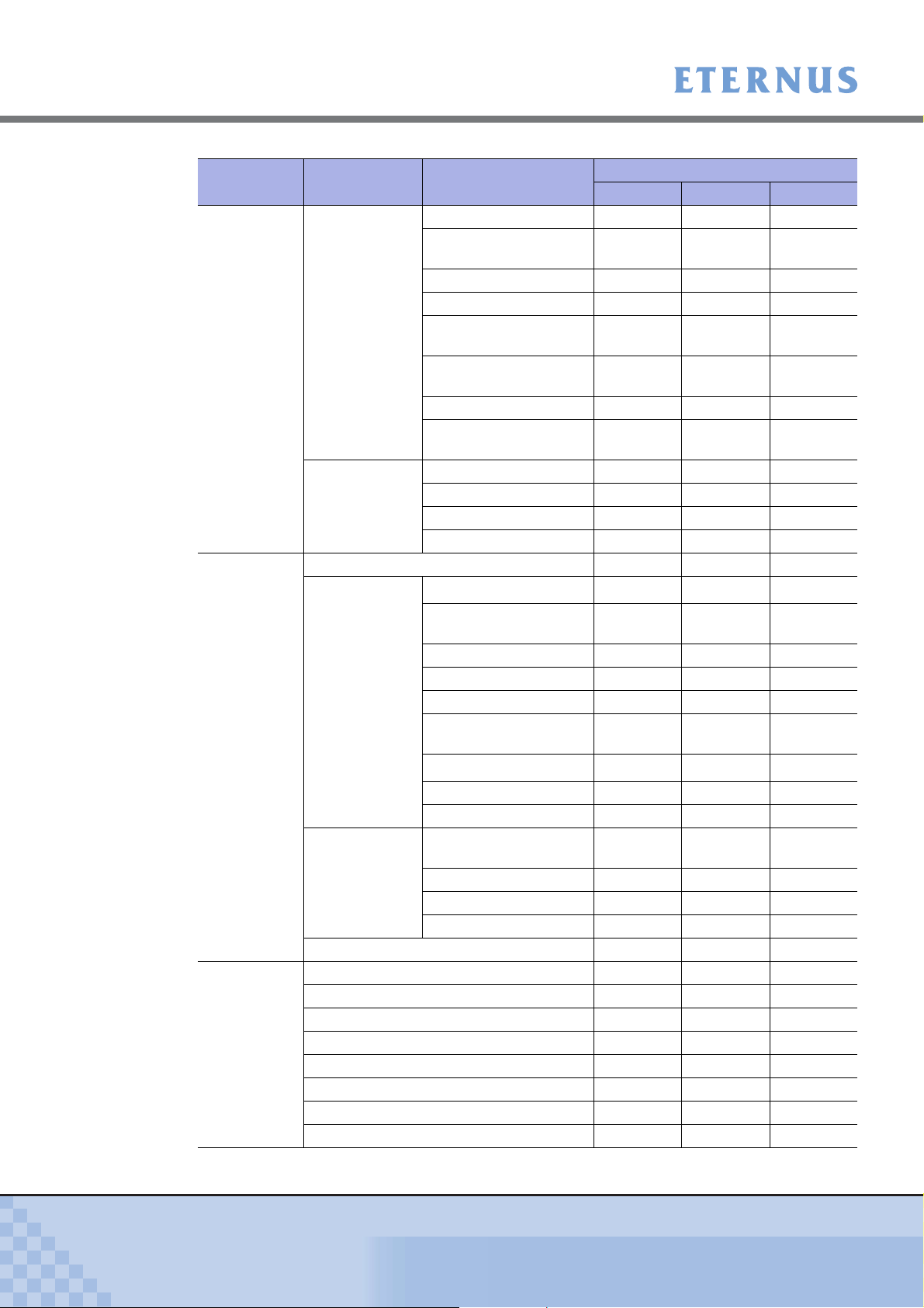
Chapter Category Function
Global
Settings
Maintenance Start/End Maintenance −−OK
Diagnosis Display Event Log OK OK OK
System
Settings
Host I/F
Management
Hardware
Maintenance
Firmware
Maintenance
Clear Sense Data −−OK
Export/Delete Log − OK OK
Export Panic Dump − OK OK
Start/Stop Performance Monitoring − OK OK
Display Performance Information OK OK OK
Display Error Information − OK OK
Export Configuration −−OK
Get G-List −−OK
Modify Date and Time − OK OK
Modify Storage System
Name
Setup Encryption Mode − OK OK
Change Box ID − OK OK
Setup Power
Management
Setup Subsystem
Parameters
Setup Disk Patrol −−OK
Setup SMI-S
Environment
Set Port parameters − OK OK
Setup Host − OK OK
Setup Host Response − OK OK
Modify Reset Group − OK OK
Hot Maintenance
Concurrent
Preventive Maintenance
Force Disable −−OK
Force Enable −−OK
Add Drive Enclosure − OK OK
Remove Drive
Enclosure
Add Disk
Reduce Disk −−OK
Add Controller Module − OK OK
Apply Controller
Firmware
Register Disk Firmware −−OK
Apply Disk Firmware −−OK
Delete Disk Firmware −−OK
(*1)
(*1)
Monitor Standard Advanced
− OK OK
− OK OK
−−OK
−−OK
−−−
−−OK
−−OK
−−−
−−OK
User Role
P2X0-0700-02ENZ0
ETERNUS DX60/DX80 Web GUI User Guide
23
Copyright 2009 FUJITSU LIMITED
Page 24
Chapter 2 Startup and Shutdown
> 2.5 Operation Screens
Chapter Category Function
Utilities Shutdown/Restart Storage System −−OK
Initialize System Disks −−OK
Cache
Utilities
Recovery
Utilities
Diagnostic
Utilities
Manage Pinned Data −−OK
Force Write Back −−OK
Apply Configuration −−OK
Backup Configuration −−OK
Reset Backup/Restore
Fail
Force Restore −−OK
Reset Machine Down
Recovery Fail
Reboot All CMs −−OK
Perform Disk Diagnostic −−OK
Perform RAID Group
Diagnostic
Monitor Standard Advanced
−−OK
−−OK
−−OK
User Role
OK: Available −: Not available
*1: Function does not require any operation from GUI.
• Some functions are not displayed for some firmware versions and
device model names.
• "5.3.4 Encrypt Volume" (page 99)
the "6.4.3 Setup Encryption Mode" (page 187)
function will be available after using
function. However, when
the encryption function is not available, the "Setup Encryption Mode" is
not displayed in the menu.
P2X0-0700-02ENZ0
ETERNUS DX60/DX80 Web GUI User Guide
24
Copyright 2009 FUJITSU LIMITED
Page 25
Chapter 3 Initial Setup
This chapter describes the Initial Setup menu. This menu supports the initial setup required
before starting operations.
● Set Date and Time
This screen is used to set the time/date and time zone (device location) of the internal clock.
● Set Storage System Name
This screen is used to set the name, administrator, and installation site of the ETERNUS
DX60/DX80 Disk storage system.
Information registered in this screen is used for the following functions and screens:
- Network management using SNMP
- Storage system name displayed in logon screen and operation screens
- Friendly Name (storage system name)
*1: VDS is a storage management function of the Windows Server®.
(*1)
for Virtual Disk Service (VDS)
● Change Password
Change the password for the default account before starting operations.
● Setup Network Environment
Set the environment for the ETERNUS DX60/DX80 Disk storage system to communicate on
the network such as IP address and subnet mask.
Note that the value specified in the Initial Setup menu can be changed subsequently. Refer to the
following sections for details.
Initial Setup Refer to:
Set Date and Time
Set Storage System Name
Change Password
Setup Network Environment
Refer
Refer
Refer
Refer
"6.4.1 Modify Date and Time" (page 184)
"6.4.2 Modify Storage System Name" (page 186)
"6.1.2 Change User Password" (page 144)
"6.2.1 Setup Network Environment" (page 147)
P2X0-0700-02ENZ0
ETERNUS DX60/DX80 Web GUI User Guide
25
Copyright 2009 FUJITSU LIMITED
Page 26
Chapter 3 Initial Setup
>
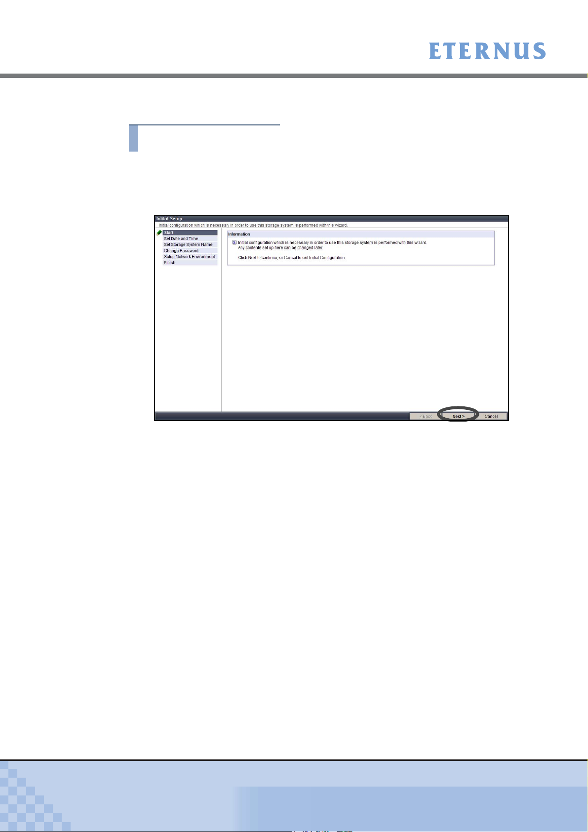
Start the Initial Setup. The initial setup procedure is as follows:
Procedure
1 Click the [Initial Setup] menu on the [Easy Setup] tab.
→ The Start screen of the [Initial Setup] function appears.
2 Click the [Next >] button.
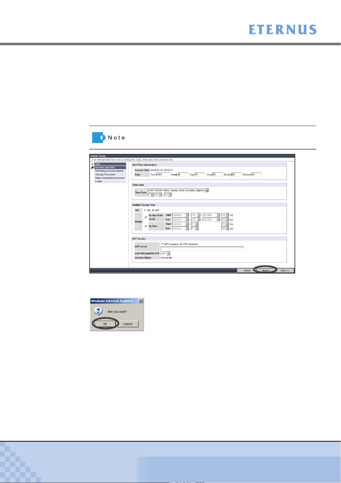
→ Initial Setup starts. The "Set Date and Time" screen appears.
3 Set the following parameters, and click the [Next >] button.
• Date/Time Information
- Current Time
Current date and time setting is displayed.
- Date
To change the "Current Time", input the new date and time.
• Time Zone
Set the time difference (GMT).
- Time Zone
Select the Time Zone from the list box. If the appropriate Time Zone does not exist,
select "Direct Input", and specify the time difference using "+" or "-", hour, and
minute.
• Daylight Saving Time
- Set
Select whether to set the Daylight Saving Time "ON" or "OFF" with the radio button.
- Range
If "Set" is "ON", set the Daylight Saving Time period. Select "by day of the week" or
"by Date" with the radio button, and input the required parameters.
P2X0-0700-02ENZ0
ETERNUS DX60/DX80 Web GUI User Guide
26
Copyright 2009 FUJITSU LIMITED
Page 27
Chapter 3 Initial Setup
>
• NTP Service
- NTP server
Select "NTP enabled" or "NTP disabled" with the ra dio but t o n . When NTP is
enabled, input the IP address or domain name for the NTP server in the text box.
ETERNUS DX60/DX80 is synchronized with the NTP server in a step mode fashion.
- LAN Port used for NTP
Select the LAN port to be used for NTP connection from "MNT" or "RMT".
- Access Status
Access state to the NTP server is displayed.
Click the [Skip >>] button to move on to the next screen without
setting.
→ A confirmation screen appears.
4 Click the [OK] button.
→ The date and time setting is set, and the "Set Storage System Name" screen appears.
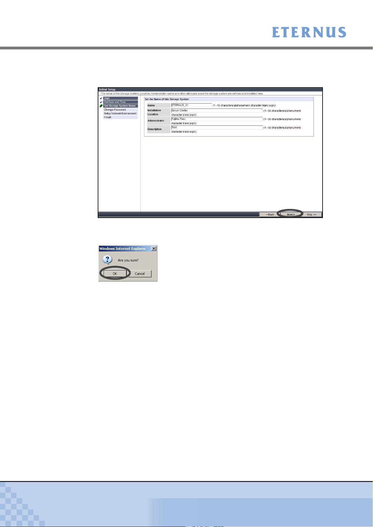
5 Set the following parameters, and click the [Next >] button.
Values specified in this screen are used for SNMP.
• Name
Enter the storage system name between 1 to 16 alphanumeric characters and symbols
(including blanks).
• Installation Location
Enter the instillation location of the ETERNUS DX80 or ETERNUS DX60 Disk storage
system between 1 to 50 alphanumeric characters and symbols (including blanks).
• Administrator
Enter the name of system administrator between 1 to 50 alphanumeric characters and
symbols (including blanks).
P2X0-0700-02ENZ0
ETERNUS DX60/DX80 Web GUI User Guide
27
Copyright 2009 FUJITSU LIMITED
Page 28
Chapter 3 Initial Setup
>
• Description
Enter the description of the ETERNUS DX80 or ETERNUS DX60 Disk storage system
between 1 to 50 alphanumeric characters and symbols (including blanks).
→ A confirmation screen appears.
6 Click the [OK] button.
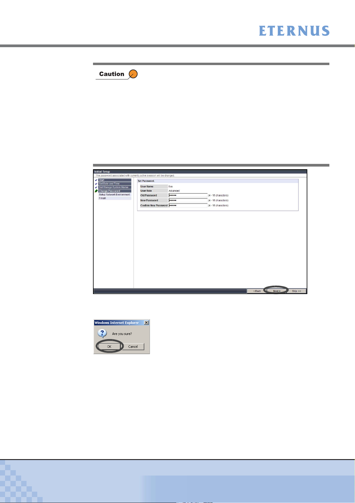
→ The storage system name is set, and the "Change Password" screen appears.
7 Set the following parameters, and click the [Next >] button.
• User Name
The current (your) user account name is displayed.
• User Role
The current (your) user role is displayed.
• Old Password
Enter the current password.
• New Password
Enter the new password between 4 to 16 characters.
Alphanumeric characters and symbols ([!], [-], [_], [.]) can be used.
• Confirm New Password
Enter the same character strings as the value entered in the "New Password" field for
confirmation.
P2X0-0700-02ENZ0
ETERNUS DX60/DX80 Web GUI User Guide
28
Copyright 2009 FUJITSU LIMITED
Page 29
Chapter 3 Initial Setup
>
When changing a user password, an error occurs in the following
conditions.
• When the "Old password" does not match the current password
• When the "Old password", "New Password", and/or "Confirm
New Password" is not entered
• When the password does not match the confirmation password
• When the password is less than 4, or more than 16 characters (If
17 or more characters are entered, ETERNUS DX60/DX80
ignores the 17th and later characters, and the password is regis-
tered using the first 16 characters only)
• When the password includes characters other than alphanumeric
characters and symbols ([!], [-], [_], [.])
P2X0-0700-02ENZ0
→ A confirmation screen appears.
8 Click the [OK] button.
→ The password is changed, and the "Setup Network Environment" screen appears.
ETERNUS DX60/DX80 Web GUI User Guide
29
Copyright 2009 FUJITSU LIMITED
Page 30
Chapter 3 Initial Setup
>
9 Set the following parameters, and click the [Next >] button.
• Select Network Port
Select the port to be used from the "MNT" or "RMT".
• Interface
- Speed and Duplex
Select the communication speed and mode from the following. The default setting is
[Auto Negotiation].
• Auto Negotiation
•1Gbps
• 100Mbps Half
•100Mbps Full
• 10Mbps Half
• 10Mbps Full
- Master CM IP Address
Enter the IP address (0 to 255) for the Master CM in the ETERNUS DX60/DX80
Disk storage system.
- Slave CM IP Address
Enter the IP address (0 to 255) for the Slave CM in the ETERNUS DX60/DX80
Disk storage system. This setting is required to duplicate LAN path.
When the ETERNUS DX60/DX80 has only one CM, a Slave IP
address cannot be specified.
- Subnet Mask
Set the Subnet Mask (0 to 255) for the ETERNUS DX60/DX80 Disk storage system.
- Default Gateway
Set the Gateway address (0 to 255) for the ETERNUS DX60/DX80 Disk storage
system.
- Primary DNS
Set the IP address for the Primary DNS server (0 to 255) for the ETERNUS DX60/
DX80 Disk storage system.
- Secondary DNS
Set the IP address for the Secondary DNS server (0 to 255) for the ETERNUS
DX60/DX80 Disk storage system.
• Allowed IP List
The value entered in this field is enabled when the Gateway has been set.
Set the destination network address (IP address and Subnet Mask).
Up to 16 addresses can be set. Make sure to set the IP address and Subnet Mask in
pairs.
P2X0-0700-02ENZ0
ETERNUS DX60/DX80 Web GUI User Guide
30
Copyright 2009 FUJITSU LIMITED
Page 31

Chapter 3 Initial Setup
>
Note the following when specifying the IP address and Subnet Mask.
• Specify the IP address using IPv4 notation (character string in
d.d.d.d format based on the 256 radix system).
• RMT port is used when it is required to use the dedicated network
for Remote Support. IP addresses for the RMT port and MNT port
must be in different subnets.
• "Slave CM IP Address" is specified when connecting to the Slave
CM. IP addresses for the Slave CM and Master CM must be in
the same subnet.
• Specify the IP address of "Default Gateway" when allowing
access from outside of the subnetwork. The IP address must be
in the same subnetwork as the port.
• For "Allowed IP List", specify the IP address or network address
that allows access to the ETERNUS DX60/DX80. These settings
are not required for access from the network address (same sub-
network) which the ETERNUS DX60/DX80 belongs to.
For the two CMs in the ETERNUSDX60/DX80, the CM that has the
priority to manage the device is called the Master CM, and the other
is called the Slave CM. If a CM or LAN failure occurs, ETERNUS
DX60/DX80 changes the Master CM automatically. The IP address
for prior Master CM is taken over to the new Master CM. Specifying
an IP address for the Slave CM enables forcible changing of the
Master CM. When an error occurs and access to the Master CM is
disabled, users can access the Slave CM and change the Master
CM.
P2X0-0700-02ENZ0
→ A confirmation screen appears.
ETERNUS DX60/DX80 Web GUI User Guide
31
Copyright 2009 FUJITSU LIMITED
Page 32

Chapter 3 Initial Setup
>
10 Click the [OK] button.
→ The Network Environment is set, and the "Finish" screen appears.
11 Click the [Finish] button.
→ The [Initial Setup] completes.
Device setting operation cannot be continued if the IP address is
changed. Logon again with the new IP address is required.
End of procedure
P2X0-0700-02ENZ0
ETERNUS DX60/DX80 Web GUI User Guide
32
Copyright 2009 FUJITSU LIMITED
Page 33

Chapter 4 Status Menu
This chapter describes the status display menu for the storage system, RAID groups, volumes,
and Advanced Copy function.
4.1 Storage System Status
This function is used to check the status of components configuring the ETERNUS DX60/DX80.
Status of each component in the ETERNUS DX60/DX80 is monitored periodically, and the result
is displayed as a general status image with character strings.
● General Status
The general status of ETERNUS DX60/DX80 is displayed as an image with character strings
in the Global Header.
The general status is determined by each component status.
P2X0-0700-02ENZ0
A "Normal (green)" general status image indicates normal status, while other color images
indicate a failure.
The following table shows an each status images.
Image Description
ETERNUS DX60/DX80 is in normal state.
(Green)
"Not Ready" is a status where an abnormality is detected at a
(Red)
(Red)
(Orange)
(Yellow)
(Gray)
ETERNUS DX60/DX80 Web GUI User Guide
power-off, and I/O access from the host cannot be received.
ETERNUS DX60/DX80 is in error state.
ETERNUS DX60/DX80 is under maintenance.
ETERNUS DX60/DX80 is in warning state.
The component is installed in the ETERNUS DX60/DX80, but not
used.
33
Copyright 2009 FUJITSU LIMITED
Page 34

Chapter 4 Status Menu
> 4.1 Storage System Status
● General status image display priority
A general status image is determined by integrated status of components such as Controller
Enclosure, Drive Enclosure, and cables, which configures the ETERNUS DX60/DX80.
The following shows the general status display priority.
High ← (Red: Not Ready) − (Red: Error) − (Orange: During
maintenance work) − (Yellow: Warning) − (Green: Normal) −
(Gray: Installed, but not used) → Low
When the general status is changed, check the component status. Expand the device tree in the
[Storage System Status] menu on the [Status] tab, and select the target component.
● Component Status
Status of each component is displayed as a status symbol in the device tree of [Storage
System Status] menu on the [Status] tab.
The following table shows the component status symbols.
Symbol Description
(Green)
(Red)
(Yellow)
(Orange)
(Blue)
(Gray)
The component is in normal status.
An error occurs in the component.
The component requires the preventive maintenance.
The component is under maintenance.
The component is installed, but not used.
(Caution)
If a disk is in this state, "Normal (green)" is displayed instead of "Warning
(yellow)" as a general status.
Status other than described above is detected in the component.
P2X0-0700-02ENZ0
● Component list
The following table shows the each component name in the device tree displayed on the left
of the [Storage System Status] menu.
Component name Description Remarks
Enclosure
(Storage system name
registered in the "Chapter 3
Initial Setup" (page 25) or
"6.4.2 Modify Storage Sys-
tem Name" (page 186))
Controller Enclosure Controller enclosure −
Drive Enclosure Drive enclosure −
Controller Module Controller module Displayed under the "Controller
Expander Expander Displayed under the "Drive
ETERNUS DX60/DX80 Web GUI User Guide
Storage system name −
Enclosure".
Enclosure".
34
Copyright 2009 FUJITSU LIMITED
Page 35

Chapter 4 Status Menu
> 4.1 Storage System Status
Port Host I/F port Displayed under the "Controller
Power Supply Unit PSU (Power Supply Unit) Displayed under the "Controller
Disks All disks in the device
Disk Each disk in the controller
SAS Cable SAS cable −
The procedure to display the storage system status is as follows:
Procedure
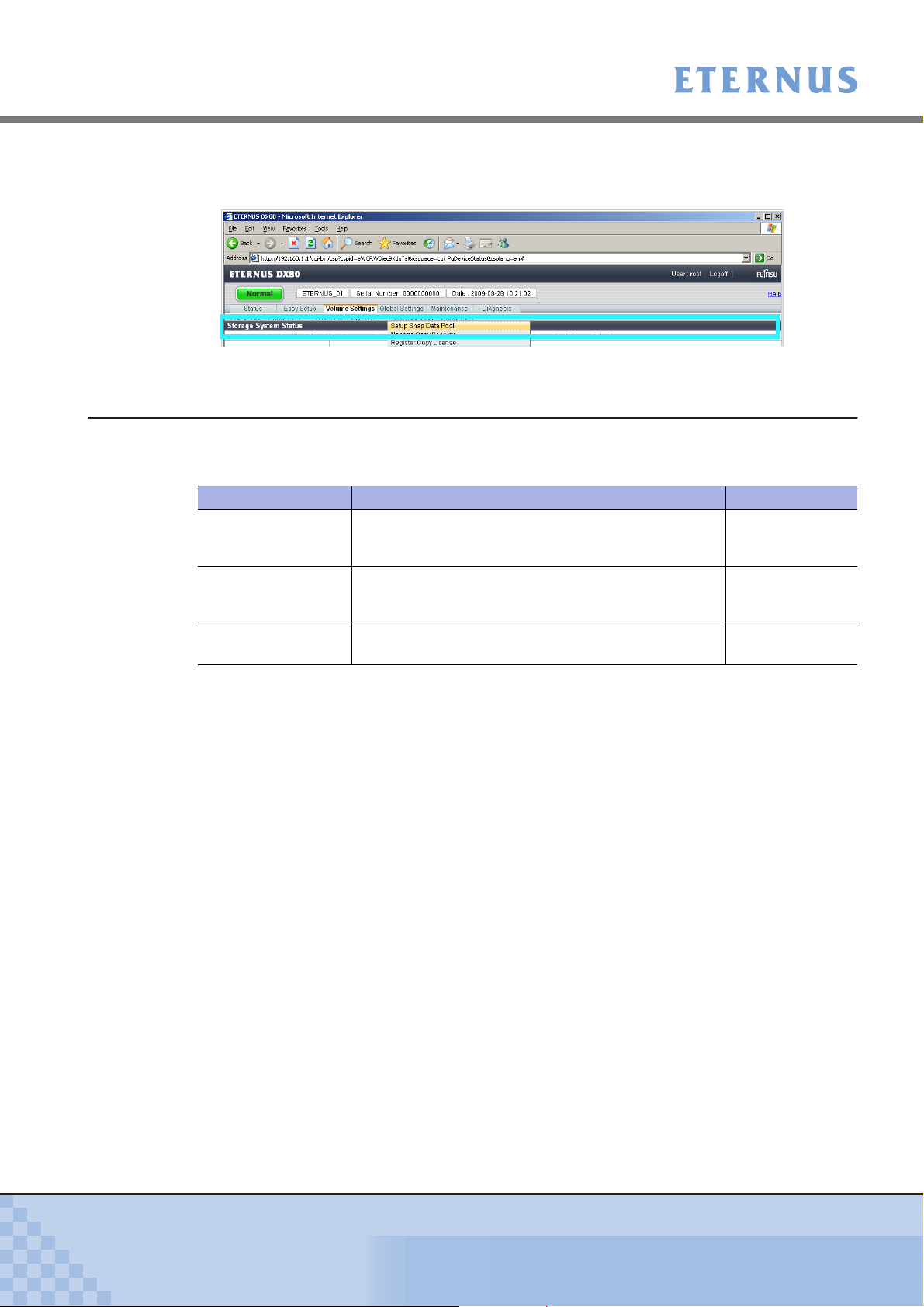
1 Click the [Storage System Status] menu on the [Status] tab.
→ The [Storage System Status] screen appears.
Component name Description Remarks
Module".
Enclosure" and "Drive
Enclosure".
Displayed under the "Disks".
enclosure or drive enclosure
The device tree in the left of the screen displays the components that configure the
ETERNUS DX60/DX80.
P2X0-0700-02ENZ0
ETERNUS DX60/DX80 Web GUI User Guide
35
Copyright 2009 FUJITSU LIMITED
Page 36

Chapter 4 Status Menu
> 4.1 Storage System Status
2 Click the component icon to display the status.
→ Detailed information of the selected component is displayed on the right of the screen.
For details about displayed information, refer to the following sections.
4.1.1 Storage System
Detailed information of the ETERNUS DX60/DX80 is displayed.
● Enclosure Status Display
The following contents are displayed for the enclosure status display.
Display contents Description
Enclosure View
Name
When clicking the [Turn on locator beacon] button, "IDENTIFY LED"
on the ETERNUS DX60/DX80 front cover blinks blue or turns off.
This button is used to identify the target controller or drive enclosure.
End of procedure
(*1)
Storage system name ("Friendly Name" for the VDS
Refer to "6.4.2 Modify Storage System Name" (page 186)
procedure to register the storage system name.
)
for detailed
P2X0-0700-02ENZ0
Model Name Model of the ETERNUS DX60/DX80
Serial Number Serial number of the ETERNUS DX60/DX80
Status General status of the ETERNUS DX60/DX80
Cache Mode Operational state of the cache (factor of "Write Through" state)
(Write Back Mode/Write Through Mode (Pinned Data/Battery/
Maintenance))
Remote Support Status of the remote support
(Operating/Stopping/Maintenance/Not Configured)
ETERNUS DX60/DX80 Web GUI User Guide
36
Copyright 2009 FUJITSU LIMITED
Page 37

Chapter 4 Status Menu
> 4.1 Storage System Status
Display contents Description
Operation Mode Operational state of the ETERNUS DX60/DX80
Controller Module
connected to the GUI
Firmware Version Current controller firmware version
Controller Enclosure Status of the controller enclosure
Drive Enclosure Status of the drive enclosure
System Message
No. Number of the system message
Message Details of the system message
*1: Virtual Disk Service (VDS) is a storage management function of the Windows Server®.
4.1.2 Controller Enclosure
(Active/Maintenance)
Controller module that can be controlled via GUI
This screen shows the status of controller enclosure and its components.
● Controller Enclosure Status Display
The following contents are displayed for the Controller Enclosure status display.
Display contents Description
Controller Enclosure Display
Front View Installation diagram for the front of the ETERNUS DX60/DX80
Rear View Installation diagram for the rear of the ETERNUS DX60/DX80
Information
CE information
Serial Number Serial number of the controller enclosure
Other Information Other information for the controller enclosure
Intake Temp
Exhaust Temp
Front View
Status, Capacity, Speed (rpm), Type, Usage, and RAID group of each component (disk)
Rear View
Status and Expanded Information of each component (CM and PSU) are displayed
External temperature of the ETERNUS DX60/DX80
(Normal/Error/Warning)
Internal temperature of the ETERNUS DX60/DX80
(Normal/Error/Warning)
P2X0-0700-02ENZ0
ETERNUS DX60/DX80 Web GUI User Guide
37
Copyright 2009 FUJITSU LIMITED
Page 38

Chapter 4 Status Menu
> 4.1 Storage System Status
● Controller Module Status Display
The following contents are displayed for the Controller Module status display.
Display contents Description
CM Display
Rear View Installation diagram for the rear of the ETERNUS DX60/DX80
CM Information
CM Information
Location Number of the controller module
Status Status of the controller module
Status Code Status code of the controller module
Error Code Error factor of the controller module
Memory Size (GB) Cache memory capacity of the controller module (GB)
Type Type of the Host I/F port installed in the controller module (Fibre
WWN (for FC model
or SAS model)
Part Number Component number of the controller module
Serial Number Serial number of the controller module
Hardware Revision Hardware revision of the controller module
CPU Clock
(MHz/GHz)
Active EC Edition Control (EC) number of the currently running firmware
Next EC EC number of the firmware that is to be run after the next power-on
CM Internal Parts Information
Status, Error Code, and Note for the following Parts (components) are displayed.
(Normal/Maintenance/Error/Check1/Undefined/Unconnected/
Unmounted/ Warning)
Channel (FC) model/iSCSI model/SAS model)
WWN of the controller module
Clock frequency of the CPU in the controller module
- [for FC model/iSCSI model/SAS model]
• Memory
• BE Expander
• BE EXP Port
• DI Port
• SCU
• NAND Controller
• Flash ROM
- [for FC model only]
• SAS Cable
• FC Port
- [for iSCSI model only]
• SAS Cable
• iSCSI Port
- [for SAS model only]
• SAS Port
• FE Expander
P2X0-0700-02ENZ0
ETERNUS DX60/DX80 Web GUI User Guide
38
Copyright 2009 FUJITSU LIMITED
Page 39

Chapter 4 Status Menu
> 4.1 Storage System Status
● Port Status Display (for FC model)
The following contents are displayed for the FC port status display.
Display contents Description
CM Display
Rear View Installation diagram for the rear of the ETERNUS DX60/DX80
CM Port Information
Location Number of the port
Status Status of the port
Status Code Status code of the port
Error Code Error factor of the port
Type FC port type
Connection Connection method to the host
Loop ID Allocated ID when the fixed Loop ID is used
Transfer Rate Port transfer rate
Link Status Link status
WWN WWN of the port
Host Affinity Current Host Affinity function setting (enabled or disabled)
Host Response Host response allocated to the port when the Host Affinity
Part Number Component number of the port
Serial Number Serial number of the port
Hardware
Revision
(Normal/Maintenance/Error/Undefined)
(Loop/Fabric)
(0x00 − 0x7D)
(For 4Gbps model: 4Gbps/2Gbps/1Gbps/Auto Negotiation)
(For 8Gbps model: 8Gbps/4Gbps/2Gbps/Auto Negotiation)
(For 4Gbps model: 4Gbps Link Up/2Gbps Link Up/1Gbps Link
Up/Link Down)
(For 8Gbps model: 8Gbps Link Up/4Gbps Link Up/2Gbps Link
Up/Link Down)
function is not used.
Hardware revision of the port
P2X0-0700-02ENZ0
● Port Status Display (for iSCSI model)
The following contents are displayed for the iSCSI port status display.
Display contents Description
CM Display
Rear View Installation diagram for the rear of the ETERNUS DX60/DX80
CM Port Information
Location Number of the port
Status Status of the port
(Normal/Maintenance/Error/Undefined)
Status Code Status code of the port
Error Code Error factor of the port
Type iSCSI port type
Transfer Rate Port transfer rate (1Gbps)
ETERNUS DX60/DX80 Web GUI User Guide
39
Copyright 2009 FUJITSU LIMITED
Page 40

Chapter 4 Status Menu
> 4.1 Storage System Status
Display contents Description
Link Status Link status
iSCSI Name iSCSI name of the port
iSCSI Alias Name iSCSI alias name of the port
Host Affinity Current Host Affinity function setting (enabled or disabled)
Host Response Host response allocated to the port when the Host Affinity
● Port Status Display (for SAS model)
The following contents are displayed for the SAS port status display.
Display contents Description
CM Display
Rear View Installation diagram for the rear of the ETERNUS DX60/DX80
CM Port Information
Location Number of the port
Status Status of the port
Status Code Status code of the port
Error Code Error factor of the port
Type SAS port type
Transfer Rate Port transfer rate (3Gbps)
Link Status Link status
SAS Address SAS Address of the port
Host Affinity Current Host Affinity function setting (enabled or disabled)
Host Response Host response allocated to the port when the Host Affinity
(1Gbps Link Up/Link Down)
function is not used.
(Normal/Maintenance/Error/Undefined)
(Phy#0: 3.0Gbps Link Up/1.5Gbps Link Up/Link Down)
(Phy#1: 3.0Gbps Link Up/1.5Gbps Link Up/Link Down)
(Phy#2: 3.0Gbps Link Up/1.5Gbps Link Up/Link Down)
(Phy#3: 3.0Gbps Link Up/1.5Gbps Link Up/Link Down)
function is not used.
P2X0-0700-02ENZ0
● SAS Cable Status Display
The following contents are displayed for the SAS cable status display.
Display contents Description
CM Display
Rear View Installation diagram for the rear of the ETERNUS DX60/DX80
CM SAS Cable Information
Status
Status Code Status code of the SAS cable
Error Code Error factor of the SAS cable
Status of the SAS cable
(Normal/Error/Maintenance/Warning)
ETERNUS DX60/DX80 Web GUI User Guide
40
Copyright 2009 FUJITSU LIMITED
Page 41

Chapter 4 Status Menu
> 4.1 Storage System Status
● Power Supply Unit Status Display
The following contents are displayed for the Power Supply Unit (PSU) status display.
Display contents Description
CE PSU Display
Rear View Installation diagram for the rear of the ETERNUS DX60/DX80
CE PSU Information
Location Number of the power supply unit
Status
Status Code Status code of the power supply unit
Error Code Error factor of the power supply unit
Part Number Component number of the power supply unit
Serial Number Serial number of the power supply unit
Hardware
Revision
Status of the power supply unit
(Normal/Error/Maintenance)
Hardware revision of the power supply unit
● Disks Status Display
The following contents are displayed for the Disks status display.
Display contents Description
Controller Enclosure Display
Front View Installation diagram for the front of the ETERNUS DX60/DX80
Information
Front View
Status, Capacity, Speed (rpm), Type, Usage, and RAID group for each component
(disk) are displayed
● Disk Status Display
The following contents are displayed for the Disk status display.
Display contents Description
Controller Enclosure Disk Display
Front View Installation diagram for the front of the ETERNUS DX60/DX80
Information
Location Disk slot number
Status Status of the disk
(Unknown/Available/Broken/Not Available/Not Supported/
Present/Readying/Rebuild/Copyback/Failed Usable/Spare/
Formatting/Not Format/Not Exist/Redundant Copy)
Status Code Status code of the disk
Error Code Error factor of the disk
Capacity Disk capacity (GB/TB)
Type Disk size (3.5") and type (SAS/SSD)
Speed (rpm) Speed of the disk
Usage Usage of the disk
(Data/System/Spare/-)
RAID Group RAID group where disks are registered
P2X0-0700-02ENZ0
ETERNUS DX60/DX80 Web GUI User Guide
41
Copyright 2009 FUJITSU LIMITED
Page 42

Chapter 4 Status Menu
> 4.1 Storage System Status
Display contents Description
Motor Status Status of the disk motor
Rebuild/
Copyback
Progress
Vender ID Vendor ID of the disk
Product ID Product name of the disk
Serial Number Serial number of the disk
WWN WWN for the disk
Firmware
Revision
4.1.3 Drive Enclosure
This screen shows the status of drive enclosure and its components.
(Active/In the Boot Process/Idle/In the Stop Process)
Rebuild/Copyback progress (%)
Disk firmware version
● Drive Enclosure Status Display
The following contents are displayed for the Drive Enclosure status display.
Display contents Description
Drive Enclosure Display
Front View Installation diagram for the front of the ETERNUS DX60/DX80
Rear View Installation diagram for the rear of the ETERNUS DX60/DX80
Information
DE Information
Serial Number Serial number of the drive enclosure
Other
Information
Intake Temp
Exhaust Temp
Front View
Status, Capacity, Speed (rpm), Type, Usage, and RAID group of each component (disk)
Rear View
Status and Expanded Information of each component (EXP and PSU) are displayed
Other information for the drive enclosure
External temperature of the ETERNUS DX60/DX80
(Normal/Error/Warning)
Internal temperature of the ETERNUS DX60/DX80
(Normal/Error/Warning)
● Expander Status Display
P2X0-0700-02ENZ0
The following contents are displayed for the Expander status display.
Display contents Description
Drive Enclosure Display
Rear View Installation diagram for the rear of the ETERNUS DX60/DX80
ETERNUS DX60/DX80 Web GUI User Guide
42
Copyright 2009 FUJITSU LIMITED
Page 43

Chapter 4 Status Menu
> 4.1 Storage System Status
Display contents Description
DE EXP Information
DE EXP Information
Status
Status Code Status code of the expander
Error Code Error factor of the expander
WWN WWN of the expander
Part Number Component number of the expander
Serial Number Serial number of the expander
Hardware
Revision
Active EC EC number of the currently running firmware
Next EC EC number of the firmware that is to be run after the next power-on
DE EXP Internal Parts Information
Status and error code of each component (SAS Cable) are displayed
Status of the expander
(Normal/Maintenance/Error/Undefined/Warning)
Hardware revision of the expander
● SAS Cable Status Display
The following contents are displayed for the SAS cable status display.
Display contents Description
Drive Enclosure Display
Rear View Installation diagram for the rear of the ETERNUS DX60/DX80
DE EXP SAS Cable Information
Status
Status Code Status code of the SAS cable
Error Code Error factor of the SAS cable
Status of the SAS cable
(Normal/Error/Maintenance/Warning)
● Power Supply Unit Status Display
The following contents are displayed for the Power Supply Unit (PSU) status display.
Display contents Description
DE PSU Display
Rear View Installation diagram for the rear of the ETERNUS DX60/DX80
DE PSU Information
Location Number of the power supply unit
Status
Status Code Status code of the power supply unit
Error Code Error factor of the power supply unit
Part Number Component number of the power supply unit
Serial Number Serial number of the power supply unit
Hardware
Revision
Status of the power supply unit
(Normal/Error/Maintenance)
Hardware revision of the power supply unit
P2X0-0700-02ENZ0
ETERNUS DX60/DX80 Web GUI User Guide
43
Copyright 2009 FUJITSU LIMITED
Page 44

Chapter 4 Status Menu
> 4.1 Storage System Status
● Disks Status Display
The following contents are displayed for the Disks status display.
Display contents Description
Drive Enclosure Display
Front View Installation diagram for the front of the ETERNUS DX60/DX80
Information
Front View
Status, Capacity, Speed (rpm), Type, Usage, and RAID group for each component (disk)
are displayed
● Disk Status Display
The following contents are displayed for the Disk status display.
Display contents Description
Drive Enclosure Disk Display
Front View Installation diagram for the front of the ETERNUS DX60/DX80
information
Location Disk slot number
Status Status of the disk
Status Code Status code of the disk
Error Code Error factor of the disk
Capacity Disk capacity (GB/TB)
Type Disk size (3.5") and type (SAS/SSD)
Speed (rpm) Speed of the disk
Usage Usage of the disk (Data/System/Spare/-)
RAID Group RAID group where disks are registered
Motor Status Status of the disk motor
Rebuild/
Copyback
Progress
Vender ID Vendor ID of the disk
Product ID Product name of the disk
Serial Number Serial number of the disk
WWN WWN for the disk
Firmware
Revision
(Unknown/Available/Broken/Not Available/Not Supported/Present/
Readying/Rebuild/Copyback/Failed Usable/Spare/Formatting/
Not Format/Not Exist/Redundant Copy)
(Active/In the Boot Process/Idle/In the Stop Process)
Rebuild/Copyback progress (%)
Disk firmware version
P2X0-0700-02ENZ0
ETERNUS DX60/DX80 Web GUI User Guide
44
Copyright 2009 FUJITSU LIMITED
Page 45

Chapter 4 Status Menu > 4.2 RAID Group Status
4.2 RAID Group Status
The [RAID Group Status] displays the status of RAID groups registered in the ETERNUS DX60/
DX80.
The procedure to display the RAID group status is as follows:
Procedure
1 Click the [RAID Group Status] menu on the [Status] tab.
→ The [RAID Group Status] screen appears.
The tree and list of the registered RAID groups are displayed.
2 Click the target RAID group icon in the tree or link in the "RAID Group List" to
display detailed information.
P2X0-0700-02ENZ0
ETERNUS DX60/DX80 Web GUI User Guide
45
Copyright 2009 FUJITSU LIMITED
Page 46

Chapter 4 Status Menu
> 4.2 RAID Group Status
→ The detailed information of the RAID group is displayed.
End of procedure
P2X0-0700-02ENZ0
ETERNUS DX60/DX80 Web GUI User Guide
46
Copyright 2009 FUJITSU LIMITED
Page 47

Chapter 4 Status Menu > 4.3 Volume Status
4.3 Volume Status
The [Volume Status] displays the status of volumes registered in the ETERNUS DX60/DX80.
The procedure to display the volume status is as follows:
Procedure
1 Click the [Volume Status] menu on the [Status] tab.
→ The [Volume Status] screen appears.
The tree and list of the registered volumes are displayed.
2 Click the target volume icon in the tree or link in the "Volume List" to display
detailed information.
P2X0-0700-02ENZ0
ETERNUS DX60/DX80 Web GUI User Guide
47
Copyright 2009 FUJITSU LIMITED
Page 48

Chapter 4 Status Menu
> 4.3 Volume Status
→ Detailed information of the volume is displayed.
The volume number and the location of the volume in the RAID
group may be different.
End of procedure
P2X0-0700-02ENZ0
ETERNUS DX60/DX80 Web GUI User Guide
48
Copyright 2009 FUJITSU LIMITED
Page 49

Chapter 4 Status Menu > 4.4 Advanced Copy Status
4.4 Advanced Copy Status
The [Advanced Copy Status] displays the Advanced Copy related status.
The procedure to display the Advanced Copy status is as follows:
Procedure
1 Click the [Advanced Copy Status] menu on the [Status] tab.
→ The [Advanced Copy Status] screen appears.
Current Advanced Copy status and list of sessions are displayed.
P2X0-0700-02ENZ0
End of procedure
ETERNUS DX60/DX80 Web GUI User Guide
49
Copyright 2009 FUJITSU LIMITED
Page 50

Chapter 5 Configuration
This chapter describes the ETERNUS DX60/DX80 configuration related menu.
The following menus are provided:
• Configuration Wizard
• RAID Group Management
• Volume Management
• Advanced Copy Management
5.1 Configuration Wizard
The [Configuration Wizard] function provides series of settings required for ETERNUS DX60/
DX80 operation on the wizard screen.
This function provides configurations in the following order: Create RAID Group, Create Volume,
Define Host, Configure Affinity Group, and Define LUN Mapping.
Also, adding volumes and changing settings for existing RAID groups are available.
• The value specified in each screen is immediately reflected to the
ETERNUS DX60/DX80. Even if the operation is canceled in the middle
of it, the specified contents cannot be canceled.
• Perform "6.5.1 Set Port Parameters" (page 195)
Configuration Wizard. When using the Host Affinity functions, make sure
to "Enable" the Host Affinity setting of the port.
Refer to "6.5 Host I/F Management" (page 193)
host affinity
before starting the
for details about the
● Create RAID Group
Create a RAID group (group of disks configuring RAID in the device) on this screen.
● Create Volume
Create volumes (disk area in the RAID group) on this screen. The server recognizes the
volume as units of RAID configuration.
● Define Host
Register the server information to be connected to the ETERNUS DX60/DX80 via a port.
This setting is not needed when the Host Affinity function is not used.
P2X0-0700-02ENZ0
ETERNUS DX60/DX80 Web GUI User Guide
50
Copyright 2009 FUJITSU LIMITED
Page 51

Chapter 5 Configuration
> 5.1 Configuration Wizard
● Configure Affinity Group
Creates the group of volumes to be recognized from the server (affinity group).
Associate a server recognized Logical Unit Number (LUN) and volume numbers.
The server recognizes the affinity group using the Host Affinity setting that allocates the
affinity group to the server.
This setting is not needed when the host affinity function is not used.
● Define LUN Mapping
Specify the volume to be recognized from the server.
• When the host affinity function is used
Allocate the affinity group for each server connected to the port (Host Affinity setting).
• When the host affinity function is not used
Allocate the volume number managed in the ETERNUS DX60/DX80 and server recognized
LUN for each port (LUN mapping setting).
Note that the value specified in the Configuration Wizard menu can be changed subsequently.
Refer to the following sections for details.
Configuration Wizard Refer to
Create RAID Group
Refer
"5.2.1 Create RAID Group" (page 69)
Create Volume
Define Host
Configure Affinity Group
Define LUN Mapping
Refer
Refer
Refer
"5.3.1 Create Volume" (page 93)
"6.5.2 Setup Host" (page 202)
"5.3.10 Configure LUN Mapping" (page 112)
The following shows the procedure of configuration wizard:
Procedure
1 Click the [Configuration Wizard] button on the [Easy Setup] tab.
→ The [Configuration Wizard] menu appears.
P2X0-0700-02ENZ0
ETERNUS DX60/DX80 Web GUI User Guide
51
Copyright 2009 FUJITSU LIMITED
Page 52

Chapter 5 Configuration
> 5.1 Configuration Wizard
2 Click the [Start] button.
→ The Configuration Wizard starts. The [Create RAID Group] screen appears.
3 Set the following items, and click the [Next >] button.
Select the RAID group creating method from the following:
• Create RAID Group (Disks are assigned automatically)
Creates a RAID group with an automatically selected disk.
• Create RAID Group (Disks are selected manually)
Creates a RAID group with a user specified disk.
• Select existing RAID Group
Creates volumes in an existing RAID group of ETERNUS DX60/DX80.
When this item is selected, the "Select Target RAID Group" field is displayed. Select
the RAID group to create volumes. Note that Step 4
procedure are skipped in this method.
- Create RAID Group (Disks are assigned automatically)
and Step 5 of in the following
P2X0-0700-02ENZ0
ETERNUS DX60/DX80 Web GUI User Guide
52
Copyright 2009 FUJITSU LIMITED
Page 53

Chapter 5 Configuration
> 5.1 Configuration Wizard
- Create RAID Group (Disks are selected manually)
- Select existing RAID Group
→ When "Create RAID Group (Disks are assigned automatically)" or "Create RAID Group
(Disks are selected manually)" is selected: Move on to Step 4
When "Select existing RAID Group" is selected: Move on to Step 6
.
.
P2X0-0700-02ENZ0
ETERNUS DX60/DX80 Web GUI User Guide
53
Copyright 2009 FUJITSU LIMITED
Page 54

Chapter 5 Configuration
> 5.1 Configuration Wizard
4 Specify the following items, and click the [Create] button.
• RAID Group Name
Enter the RAID group name to be created.
Up to 16 alphanumeric characters and symbols (including blanks) can be used
(required).
• RAID Level
Select the RAID level from the following:
- RAID0
- RAID1
- RAID1+0
- RAID5
- RAID6
- RAID5+0
• Disk Capacity
Select the capacity and number of disk to be used in the RAID group.
Available disk capacity is as follows:
- 300GB SAS
- 450GB SAS
- 750GB SAS
- 1TB SAS
- 100GB SSD
- 200GB SSD
Available number of disks varies depending on the specified RAID level.
- RAID0: 2 − 16
- RAID1: 2
- RAID1+0: 4 − 32 (even number)
- RAID5: 3 − 16
- RAID6: 5 − 16
- RAID5+0: 6 − 32 (even number)
• Assigned CM
Select the assigned CM for the RAID group from "Automatic", "CM#0", or "CM#1".
Normally, select the "Automatic". When the "Automatic" is selected, the control CM to
be assigned varies according to the RAID group number. If the RAID group number is
an even number, CM#0 is assigned to the new RAID group. For an odd number RAID
group, CM#1 is assigned to the new RAID group.
P2X0-0700-02ENZ0
When the ETERNUS DX60/DX80 has only one CM, CM#1 cannot be
specified as the Assigned CM.
• Select Disk
When "Create RAID Group (Disks are selected manually)" is selected in Step 3, select
the disks to be registered in the RAID Group (required).
ETERNUS DX60/DX80 Web GUI User Guide
54
Copyright 2009 FUJITSU LIMITED
Page 55

Chapter 5 Configuration
> 5.1 Configuration Wizard
- Create RAID Group (Disks are assigned automatically)
• A RAID group name that is already registered in the ETERNUS
DX60/DX80 cannot be specified.
• It is not possible to select more than, or less than, the specified
number of configuration disks for each RAID level.
• RAID0 has no data redundancy. RAID1, RAID1+0, RAID5,
RAID6, and RAID5+0 are recommended for the RAID level.
• If disks of different capacities exist in a RAID group, the smallest
capacity becomes the standard, and all other disks are regarded
as having the same capacity as the smallest disk. In this case, the
remaining disk space will NOT be used.
• Different disks and types (SAS/SSD) cannot exist together in one
RAID group.
P2X0-0700-02ENZ0
ETERNUS DX60/DX80 Web GUI User Guide
55
Copyright 2009 FUJITSU LIMITED
Page 56

Chapter 5 Configuration
> 5.1 Configuration Wizard
- Create RAID Group (Disks are selected manually)
→ A confirmation screen appears.
5 Click the [OK] button.
→ A RAID Group is created. Move on to the [Create Volume] screen.
Refer to "5.2.5 Logical Device Expansion" (page 80) or "5.2.8
Change CM Ownership" (page 91) to change the setting items after
creating the RAID group.
6 Specify the following items, and click the [Create] button.
• Volume Name
Enter the volume name to be created.
Up to 16 alphanumeric characters and symbols (including blanks) can be used
(required).
• Type
Select the volume type (Open or SDV).
• Size (MB)
Specify the volume capacity to be created in units of MB.
Set the value between 24 to 8,388,607 (MB), or maximum capacity of the RAID group.
P2X0-0700-02ENZ0
When creating an SDV, the total SDV capacity (MB) and 0.1% of
the copy source volume capacity is secured in the ETERNUS
DX60/DX80. 0.1% of the copy source volume is the capacity used
for the controlling information area in the SDV.
ETERNUS DX60/DX80 Web GUI User Guide
56
Copyright 2009 FUJITSU LIMITED
Page 57

Chapter 5 Configuration
> 5.1 Configuration Wizard
• Source Volume Size (MB) (SDV only)
When SDV is selected for "Type", specify the total capacity of the copy source volume
in units of MB.
• Encryption
This item is displayed only when encryption mode is enabled.
Select whether to "Enable" or "Disable" encryption mode for the new volume.
An encrypted volume cannot be changed to a non-encrypted volume.
Refer to "6.4.3 Setup Encryption Mode" (page 187) and "5.3.4 Encrypt Volume" (page
99) for details.
• Number of Volumes
When creating multiple volumes with the same type and capacity, enter the number of
volumes to be created.
Note that all the volumes are created with the same name. Change the volume name
(refer to
"5.3.9 Set Volume Name" (page 111)) if needed.
P2X0-0700-02ENZ0
→ A confirmation screen appears.
7 Click the [OK] button.
→ Volumes are created. Move on to the [Define Host] screen.
ETERNUS DX60/DX80 Web GUI User Guide
57
Copyright 2009 FUJITSU LIMITED
Page 58

Chapter 5 Configuration
> 5.1 Configuration Wizard
8 Click the [Add] button.
This setting is not needed when the host affinity function is not used.
• For FC host
→ The "Add New FC Host" field is displayed.
• For iSCSI host
→ The "Add New iSCSI Host" field is displayed.
P2X0-0700-02ENZ0
ETERNUS DX60/DX80 Web GUI User Guide
58
Copyright 2009 FUJITSU LIMITED
Page 59

Chapter 5 Configuration
> 5.1 Configuration Wizard
• For SAS host
→ The "Add New SAS Host" field is displayed.
9 Specify the following items, and click the [OK] button.
• For FC host
- FC Port
The list of FC ports that exist in the ETERNUS DX60/DX80 is displayed.
When the fibre channel switch is connected to the
ETERNUS DX60/DX80, settings between the fibre channel
switch and server (FC host) must be completed in advance.
- WWN
Select the WWN, or directly input a WWN (required). 16 capital letters and numerals
can be used.
- Name
Input the FC Host Name (required). Up to 16 alphanumeric characters and symbols
(including blanks) can be used.
- Host Response
Specify the host response for the target host (required). Refer to "ETERNUS Disk
storage systems Server Connection Guide
(Fibre Channel)" for details.
P2X0-0700-02ENZ0
ETERNUS DX60/DX80 Web GUI User Guide
59
Copyright 2009 FUJITSU LIMITED
Page 60

Chapter 5 Configuration
> 5.1 Configuration Wizard
→ The target FC host is displayed in the "Registered FC Host List" field.
• For iSCSI host
- iSCSI Port
The list of iSCSI ports that exist in the ETERNUS DX60/DX80 is displayed.
- iSCSI Name
Select the iSCSI Name, or directly input the iSCSI Name. Between 4 and 223
alphanumeric characters and symbols (required) can be used.
In the following conditions, iSCSI Name cannot be obtained
automatically:
• When the [Discover] button is inactivated
• When "Disable" is selected for the "iSNS server" in the "Set
iSCSI Port Parameters"
- IP address
Specify the IP address of the target host (iSCSI port) (required).
- Name
Specify the target host (iSCSI port) name (required). Between 1 and 16
alphanumeric characters and symbols (including blanks) can be used.
- Host Response
Specify the host response for the target host (required). Refer to "ETERNUS Disk
storage systems Server Connection Guide (ISCSI)" for details.
- Alias Name
Specify the alias name of the target host (iSCSI port). Up to 31 alphanumeric
characters and symbols can be used.
- CHAP User ID
Specify the user ID that accesses the target host ( i S C S I p o r t ) . U p t o 2 5 5
alphanumeric characters and symbols can be used.
It is not necessary to set this item if CHAP Authentication is not performed.
P2X0-0700-02ENZ0
ETERNUS DX60/DX80 Web GUI User Guide
60
Copyright 2009 FUJITSU LIMITED
Page 61

Chapter 5 Configuration
> 5.1 Configuration Wizard
- CHAP Password
Specify the password to access the target host. Between 12 and 100 alphanumeric
characters and symbols can be used (required).
Make sure to set the user name and password in pairs.
- Confirm CHAP Password
Enter the same password as in the CHAP Password field (required).
→ The target iSCSI host is displayed in the "Registered iSCSI Host List" field.
• For SAS host
- SAS Port
The list of SAS ports that exist in the ETERNUS DX60/DX80 is displayed.
- SAS Address
Select the SAS address, or directly input a SAS address (required). 16 capital
letters and numerals can be used.
- Name
Specify the target host (SAS port) name (required). Up to 16 alphanumeric
characters and symbols (including blanks) can be used.
- Host Response
Specify the host response for the target host (required). Refer to "ETERNUS Disk
storage systems Server Connection Guide (
SAS)" for details.
P2X0-0700-02ENZ0
ETERNUS DX60/DX80 Web GUI User Guide
61
Copyright 2009 FUJITSU LIMITED
Page 62

Chapter 5 Configuration
> 5.1 Configuration Wizard
→ The target SAS host is displayed in the "Registered SAS Host List" field.
10 Click the [Next >] button.
• For FC host
P2X0-0700-02ENZ0
ETERNUS DX60/DX80 Web GUI User Guide
62
Copyright 2009 FUJITSU LIMITED
Page 63

Chapter 5 Configuration
> 5.1 Configuration Wizard
• For iSCSI host
• For SAS host
→ A confirmation screen appears.
11 Click the [OK] button.
P2X0-0700-02ENZ0
→ The specified host setting is registered. Move on to the [Configure Affinity Group]
screen.
ETERNUS DX60/DX80 Web GUI User Guide
63
Copyright 2009 FUJITSU LIMITED
Page 64

Chapter 5 Configuration
> 5.1 Configuration Wizard
12 Click the [Create] button.
This setting is required when using the host affinity function. When
the host affinity function is not used, click the [Next >] button to move
on to the " Configure LUN Mapping" setting menu.
Also, this setting is not required when using an existing affinity group
(displayed in the "List of Affinity Group(s)" field).
When using the existing affinity group, select the target group from
the "List of Affinity Group(s)" field and click the [Edit] button.
→ The "Affinity Group Setting" and "Define LUN Mapping" fields are displayed.
13 Enter the affinity group name and specify a volume number corresponding to the
LUN number, and click the [
→ A confirmation screen appears.
Set] button.
P2X0-0700-02ENZ0
ETERNUS DX60/DX80 Web GUI User Guide
64
Copyright 2009 FUJITSU LIMITED
Page 65

Chapter 5 Configuration
> 5.1 Configuration Wizard
14 Click the [OK] button.
15 Click the [Next >] button.
→ Move on to the [Define LUN Mapping] screen.
16 Select the port that is connected to the target server from the "Port List" field.
■ When using the Host Affinity function:
(1)Click the [Edit] button.
P2X0-0700-02ENZ0
→ The "Host Affinity Setting" field is displayed.
ETERNUS DX60/DX80 Web GUI User Guide
65
Copyright 2009 FUJITSU LIMITED
Page 66

Chapter 5 Configuration
> 5.1 Configuration Wizard
(2)Assign the affinity group to the server, and click the [Set] button.
→ A confirmation screen appears.
(3)Click the [OK] button.
→ Returns to the "Port List" screen.
P2X0-0700-02ENZ0
ETERNUS DX60/DX80 Web GUI User Guide
66
Copyright 2009 FUJITSU LIMITED
Page 67

Chapter 5 Configuration
> 5.1 Configuration Wizard
■ When the Host Affinity function is not used:
(1)Click the [Edit] button.
Click the [Copy] button to copy the LUN mapping information from
the other port.
→ The [Define LUN Mapping] field is displayed.
(2)Adjust the LUN mapping information for the target port, and click the [Set] button.
→ A confirmation screen appears.
P2X0-0700-02ENZ0
ETERNUS DX60/DX80 Web GUI User Guide
67
Copyright 2009 FUJITSU LIMITED
Page 68

Chapter 5 Configuration
> 5.1 Configuration Wizard
(3)Click the [OK] button.
→ Returns to the "Port List" screen.
17 Click the [Finish] button.
→ A confirmation screen appears.
18 Click the [OK] button.
→ The Configuration Wizard screen is closed.
End of procedure
P2X0-0700-02ENZ0
ETERNUS DX60/DX80 Web GUI User Guide
68
Copyright 2009 FUJITSU LIMITED
Page 69

Chapter 5 Configuration > 5.2 RAID Group Management
5.2 RAID Group Management
The following settings are available for RAID group management.
• Create/Delete RAID Group
• Assign/Release Hot Spare
• Logical Device Expansion
• Set RAID Group name
• Set Eco-mode Schedule
• Change CM Ownership
5.2.1 Create RAID Group
The RAID groups are usually set at the time of shipping. However if you wish to change the RAID
settings or add extra disks, then you need to create new RAID groups. You can confirm the
groups that are created from the [RAID Group Status] menu on the [Status] tab.
● Number of disks that can be set for each RAID level
The number of disks that can be set for each RAID level is as follows.
The available number of disks varies according to ETERNUS DX60/DX80.
RAID level Number of disks that can be created Recommended number of disks
ETERNUS DX60 ETERNUS DX80
RAID0 2 − 16 2 − 16 −
RAID1222(1D+1M)
RAID1+0 4 − 24 4 − 32 4(2D+2M), 6(3D+3M),
8(4D+4M), 10(5D+5M)
RAID5 3 − 16 3 − 16 3(2D+1P), 4(3D+1P),
5(4D+1P), 6(5D+1P)
RAID6 5 − 16 5 − 16 5(3D+2P), 6(4D+2P),
7(5D+2P)
RAID5+0 (3 − 12) × 2(3 − 12) × 2 3(2D+1P) × 2, 4(3D+1P) × 2,
5(4D+1P) × 2, 6(5D+1P) × 2
P2X0-0700-02ENZ0
ETERNUS DX60/DX80 Web GUI User Guide
69
Copyright 2009 FUJITSU LIMITED
Page 70

Chapter 5 Configuration
> 5.2 RAID Group Management
● The maximum number of RAID groups that can be set to each RAID level
The maximum number of RAID groups that can be created is 12 for the ETERNUS DX60, and
60 for the ETERNUS DX80.
The maximum number of RAID groups that can be set for each RAID level is as follows.
The available number of RAID groups varies according to each device.
RAID level Number of RAID groups that can be created
RAID0 12 60
RAID1 12 60
RAID1+0 6 30
RAID5 8 40
RAID6 4 24
RAID5+0 4 20
● The maximum number of volumes that can be set
The maximum number of volumes that can be set for each RAID group and device is as
follows.
The available number of volumes varies according to each device.
Device name per RAID group per device
ETERNUS DX60 Up to 128 Up to 512
ETERNUS DX80 Up to 128 Up to 1,024
ETERNUS DX60 ETETRNUS DX80
• RAID groups can be created when the disk satisfies all the following
conditions:
- The disk is not one that configures a RAID group
- The disk is not specified as a hot spare
- The disk status is "Available" or "Present"
• In the following conditions, RAID groups cannot be created:
- There are no disks to configure the RAID group
- When the maximum number of RAID groups has already been
created
Creating RAID groups is required before creating volumes.
The procedure to create a RAID group is as follows:
Procedure
1 Click the [Create RAID Group] under the [RAID Group Management] menu on
the [Volume Settings] tab.
→ The [Create RAID Group] screen appears.
P2X0-0700-02ENZ0
ETERNUS DX60/DX80 Web GUI User Guide
70
Copyright 2009 FUJITSU LIMITED
Page 71

Chapter 5 Configuration
> 5.2 RAID Group Management
2 Specify the following items, and click the [Next >] button.
Select one of the following items:
• Create RAID Group (Disks are assigned automatically)
Creates a RAID group with automatically selected disks.
• Create RAID Group (Disks are selected manually)
Creates a RAID group with user specified disks.
- Create RAID Group (Disks are assigned automatically)
- Create RAID Group (Disks are selected manually)
→ The "New RAID Group" field is displayed.
P2X0-0700-02ENZ0
ETERNUS DX60/DX80 Web GUI User Guide
71
Copyright 2009 FUJITSU LIMITED
Page 72

Chapter 5 Configuration
> 5.2 RAID Group Management
3 Specify the following items, and click the [Create] button.
• RAID Group Name
Enter the RAID group name to be created.
Up to 16 alphanumeric characters and symbols (including blanks) can be used
(required).
• RAID Level
Select the RAID level from the following:
- RAID0
- RAID1
- RAID1+0
- RAID5
- RAID6
- RAID5+0
• Disk Capacity
When selecting "Create RAID Group (Disks are assigned automatically)" in Step 2,
select the capacity and number of disks to be used in the RAID group.
- 300GB SAS
- 450GB SAS
- 750GB SAS
- 1TB SAS
- 100GB SSD
- 200GB SSD
Available number of disks varies depending on the specified RAID level.
- RAID0: 2 − 16
- RAID1: 2
- RAID1+0: 4 − 32 (even number)
- RAID5: 3 − 16
- RAID6: 5 − 16
- RAID5+0: 6 − 32 (even number)
• Assigned CM
Select the assigned CM for the RAID group from "Automatic", "CM#0", or "CM#1".
Normally, select the "Automatic". When the "Automatic" is selected, the control CM to
be assigned varies according to the RAID group number. If the RAID group number is
an even number, CM#0 is assigned to the new RAID group. For an odd number RAID
group, CM#1 is assigned to the new RAID group.
P2X0-0700-02ENZ0
When the ETERNUS DX60/DX80 has only one CM, CM#1 cannot be
specified as the Assigned CM.
ETERNUS DX60/DX80 Web GUI User Guide
72
Copyright 2009 FUJITSU LIMITED
Page 73

Chapter 5 Configuration
> 5.2 RAID Group Management
• Select Disk
When "Create RAID Group (Disks are selected manually)" is selected in Step 2, select
the disks to be registered in the RAID Group (required).
- Create RAID Group (Disks are assigned automatically)
• A RAID group name that is already registered in the ETERNUS
DX60/DX80 cannot be specified.
• It is not possible to select more than, or less than, the specified
number of configuration disks for each RAID level.
• RAID0 has no data redundancy. RAID1, RAID1+0, RAID5,
RAID6, and RAID5+0 are recommended for the RAID level.
• If disks of different capacities exist in a RAID group, the smallest
capacity becomes the standard, and all other disks are regarded
as having the same capacity as the smallest disk.
In this case, the remaining disk space will NOT be used.
• The different disks and types (SAS/SSD) cannot exist together in
one RAID group.
P2X0-0700-02ENZ0
ETERNUS DX60/DX80 Web GUI User Guide
73
Copyright 2009 FUJITSU LIMITED
Page 74

Chapter 5 Configuration
> 5.2 RAID Group Management
- Create RAID Group (Disks are selected manually)
→ A confirmation screen appears.
4 Click the [OK] button.
→ The RAID group is created.
5.2.2 Delete RAID Group
The [Delete RAID Group] function deletes the registered RAID groups. When a RAID group is
deleted, the status of the disks that configured the RAID group change to data disks that are not
used by any RAID group.
Refer to "5.2.5 Logical Device Expansion" (page 80) or "5.2.8
Change CM Ownership" (page 91) to change the setting items after
creating the RAID group.
End of procedure
P2X0-0700-02ENZ0
RAID groups that have volumes registered cannot be deleted. All volumes
must be deleted before deleting a RAID group. Refer to "5.3.2 Delete Vol-
ume" (page 96) for procedure to delete volumes.
ETERNUS DX60/DX80 Web GUI User Guide
74
Copyright 2009 FUJITSU LIMITED
Page 75

Chapter 5 Configuration
> 5.2 RAID Group Management
The procedure to delete RAID group is as follows:
Procedure
1 Click the [Delete RAID Group] under the [RAID Group Management] menu on
the [Volume Settings] tab.
→ The [Delete RAID Group] function screen appears.
2 Select the target RAID group, and click the [Delete] button.
→ A confirmation screen appears.
3 Click the [OK] button.
→ The selected RAID group is deleted.
5.2.3 Assign Hot Spare
The [Assign Hot Spare] function registers a hot spare, which enables automatic data copy
(Rebuild) in the background when a disk failure occurs.
Hot spare is a disk that is available as a substitute for a failed disk.
There are two types of hot spare as follows:
• Global Hot Spare
Hot spare used by all the RAID groups
• Dedicated Hot Spare
Hot spare used by the dedicated RAID group (one specific RAID group)
End of procedure
P2X0-0700-02ENZ0
ETERNUS DX60/DX80 Web GUI User Guide
75
Copyright 2009 FUJITSU LIMITED
Page 76

Chapter 5 Configuration
> 5.2 RAID Group Management
Note the following items when adding a hot spare:
• A system disk (Slot#0 to Slot#1 of the controller enclosure) cannot be
specified as a hot spare.
• A hot spare that substitutes for a failed disk must have the same or a
larger capacity than the data disk. If the hot spare capacity is smaller
than the data disk, the disk does not work as the hot spare.
• A hot spare can be specified for any disk with the exception of the
system disks.
• When switching in a hot spare for a failed disk, a hot spare with the
same capacity as the failed disk will be used fir s t . I f s u c h a h o t s p a r e
does not exist, a large capacity hot spare will be used (when there are
multiple numbers of such disks, the smallest capacity hot spare among
them is used). Note that a Global Hot Spare is used in this situation.
• When you replace a failed disk, the data is copied back from the hot
spare that is substituting for the failed disk, and the hot spare disk then
returns to a spare disk.
• When a mix of SAS disks, Nearline SAS disks, and SSDs are installed
together in the ETERNUS DX60/DX80, hot spare of each type is
required. Install the hot spare that has the same capacity as the largest
capacity disks of the same type installed in the ETERNUS DX60/DX80.
The procedure to assign a hot spare is as follows:
Procedure
1 Click the [Assign Hot Spare] under the [RAID Group Management] menu on the
[Volume Settings] tab.
→ The [Assign Hot Spare] screen appears.
2 Specify the following items, and click the [Assign] button.
• Hot Spare Type
Select from the following items:
- Global Hot Spare
Global hot spare is shared by any RAID group in the device.
- Dedicated Hot Spare
Dedicated hot spare is used by specified RAID group.
• Select an existing RAID Group
When selecting the "Dedicated Hot Spare", specify the target RAID group.
• Select Disk
Select the disk to be used as hot spare.
P2X0-0700-02ENZ0
ETERNUS DX60/DX80 Web GUI User Guide
76
Copyright 2009 FUJITSU LIMITED
Page 77

Chapter 5 Configuration
> 5.2 RAID Group Management
- When adding "Global Hot Spare"
- When adding "Dedicated Hot Spare"
P2X0-0700-02ENZ0
→ A confirmation screen appears.
3 Click the [OK] button.
→ The hot spare is added.
ETERNUS DX60/DX80 Web GUI User Guide
77
End of procedure
Copyright 2009 FUJITSU LIMITED
Page 78

Chapter 5 Configuration
> 5.2 RAID Group Management
5.2.4 Release Hot Spare
The [Release Hot Spare] function deletes a registered hot spare. A released disk can be used as
a data disk after it is registered in a RAID group.
Hot spare cannot be deleted in the following conditions:
• When the usage of the hot spare is other than "Spare"
• When the status of the hot spare is other than "Present"
• When one of the following operations is in progress:
- Registering controller firmware
- Applying controller firmware
- Registering disk firmware
- Applying disk firmware
- During the RAID group diagnosis
- During the disk diagnosis
The procedure to delete hot spare is as follows:
Procedure
1 Click the [Release Hot Spare] under the [RAID Group Management] menu on
the [Volume Settings] tab.
→ The [Release Hot Spare] screen appears.
2 Specify the following items, and click the [Release] button.
• Hot Spare Type
Select one of the following as a condition of the hot spare to be released.
- Global Hot Spare
Global hot spare is shared by any RAID group in the device.
- Dedicated Hot Spare
Dedicated hot spare is used by a specified RAID group.
• Criteria for Target Disk
This field is displayed when selecting the "Ded icated Hot Spare". If the "Specify RAID
Group" checkbox is checked, the target RAID group can be specified.
• Select Disk
Select the disk to be released as hot spare.
P2X0-0700-02ENZ0
ETERNUS DX60/DX80 Web GUI User Guide
78
Copyright 2009 FUJITSU LIMITED
Page 79

Chapter 5 Configuration
> 5.2 RAID Group Management
- When releasing "Global Hot Spare"
- When releasing "Dedicated Hot Spare"
P2X0-0700-02ENZ0
→ A confirmation screen appears.
3 Click the [OK] button.
→ The selected hot spare is deleted.
ETERNUS DX60/DX80 Web GUI User Guide
79
End of procedure
Copyright 2009 FUJITSU LIMITED
Page 80

Chapter 5 Configuration
> 5.2 RAID Group Management
5.2.5 Logical Device Expansion
The [Logical Device Expansion] function expands the capacity of an existing RAID group by add-
ing new disks or changing RAID levels.
Normally, volume expansion requires adding RAID groups. This method requires multiple disks
to be installed (used). However, this function can add disks to the existing RAID group in units of
one disk. This enables capacity expansion of RAID groups with smaller number of disk expan
sion.
This function can be performed with taking over data in the disks.
• Disks that are a different type (SAS/SSD) than the disks that configure
• Logical Device Expansion is not available in the following conditions:
-
the RAID group cannot be added.
- RAID groups are not in normal status (Rebuilding, Copybacking, or
using hot spare etc.)
- When another Logical Device Expansion is being performed
- When the target RAID level or changed RAID level is RAID5+0
- Changing RAID level to RAID0
Note that existing volume size is not changed even if the RAID level is
changed or capacity is expanded.
The procedure for Logical Device Expansion is as follows:
Procedure
1 Click the [Logical Device Expansion] under the [RAID Group Management]
menu on the [Volume Settings] tab.
→ The [Logical Device Expansion] screen appears.
P2X0-0700-02ENZ0
ETERNUS DX60/DX80 Web GUI User Guide
80
Copyright 2009 FUJITSU LIMITED
Page 81

Chapter 5 Configuration
> 5.2 RAID Group Management
2 Select the target RAID group, and click the [Next >] button.
→ The "Modify RAID Group Configuration" screen appears.
3 Specify the following items, and click the [Next >] button.
• RAID Level
Select (change) the RAID level.
Only for adding disks, changing RAID level is not required.
• Select Disk
Select (add) disks according to the new RAID level.
P2X0-0700-02ENZ0
→ A confirmation screen appears.
ETERNUS DX60/DX80 Web GUI User Guide
81
Copyright 2009 FUJITSU LIMITED
Page 82

Chapter 5 Configuration
> 5.2 RAID Group Management
4 Click the [Start] button.
→ A confirmation screen appears.
5 Click the [OK] button.
→ Logical Device Expansion is performed.
5.2.6 Set RAID Group Name
The [Set RAID Group Name] function can change the existing RAID group name.
The procedure to change RAID group name is as follows:
Procedure
1 Click the [Set RAID Group Name] under the [RAID Group Management] menu
on the [Volume Settings] tab.
→ The [Set RAID Group Name] screen appears.
End of procedure
P2X0-0700-02ENZ0
ETERNUS DX60/DX80 Web GUI User Guide
82
Copyright 2009 FUJITSU LIMITED
Page 83

Chapter 5 Configuration
> 5.2 RAID Group Management
2 Change the target RAID group name, and click the [Set] button.
Enter the volume name between 1 to 16 alphanumeric characters and symbols (including
blanks).
RAID group name that is already registered in the ETERNUS DX60/
DX80 cannot be specified.
→ A confirmation screen appears.
3 Click the [OK] button.
→ The RAID group name is changed.
5.2.7 Set Eco-mode Schedule
The [Set Eco-mode Schedule] provides the following functions:
● Eco-mode General Setting
Enables or disables the Eco-mode setting for ETERNUS DX60/DX80.
Also, this function specifies the disk monitoring time. If the disk is not accessed for a specified
time, the disk motor is inactivated
End of procedure
P2X0-0700-02ENZ0
● Eco-mode Schedule Setting
Specifies the disk operating time (term for activating disk motor constantly) as an Eco-mode
schedule.
ETERNUS DX60/DX80 Web GUI User Guide
83
Copyright 2009 FUJITSU LIMITED
Page 84

Chapter 5 Configuration
> 5.2 RAID Group Management
● Apply Eco-mode Schedule
Applies the created Eco-mode schedule for each RAID group.
If an access occurs while a motor is stopped, the disk drive is immediately spun up and access
proceeds normally after one to three minutes. If a disk drive is activated more than a set amount
of times in a day, a state of increased access frequency is assumed and the Eco-mode will
cease stopping the disk drive motor. Disk operation time varies depending on the Eco-mode
schedule settings and disk access. The following shows examples:
• Operation schedule is set as 9:00 to 21:00, the allowed number of activations is one time, and
there are no accesses outside of the scheduled period
21:009:001:00
0:00
Stopped
First
activation
Scheduled Operation
Drive Motor Running
Motor is spun up 30 minutes
before start of operating time
Motor is stopped 30 minutes
after end of operating time
Stopped
• Operation schedule is set as 9:00 to 21:00, the allowed number of activations is one time, and
there are accesses outside of the scheduled period
No. of activations
reset to 0 at 0:00
Access
Access finishes
Drive Motors Running
Drive Motors Running
Disk motors left running
after access has finished
because this was
the 2nd activation
Reset:
Count: 0
First activation:
Count: 1
Scheduled Operation
Drive Motors Running
Motors spun up 30 minutes
before start of scheduled time
Second
activation:
Count: 2
21:009:001:00 0:00
Access OK in
Motors stopped 30 minutes
after end of scheduled time
1 - 3 minutes
P2X0-0700-02ENZ0
ETERNUS DX60/DX80 Web GUI User Guide
84
Copyright 2009 FUJITSU LIMITED
Page 85

Chapter 5 Configuration
> 5.2 RAID Group Management
• To perform schedule operations using this function, the Eco-mode
setting for the ETERNUS DX60/DX80 must be enabled.
• Eco mode is not available for the following disks.
- System disks
- Hot spares
- SSD
- Disks in a RAID group the satisfies the following conditions:
• A RAID group including system disks
• A RAID group where no volume is registered
• A RAID group where SDPVs are registered
• If any of the following conditions occur during the Eco-mode scheduled
time, the disk motor is not inactivated. Note that the Eco-mode schedule
will be re-enabled when these conditions have finished.
- Target RAID group or volume status is other than "Available"
- Performing functions that changes RAID group or volume
configuration
- During maintenance
- During host access
- During disk or RAID group diagnosis
- Exporting G-List
- Changing assigned CM for RAID group
- Module error related to access path to the controller modules and
disks is detected
• When setting the Eco-mode for the Advanced Copy source/destination,
it is necessary to schedule a disk motor to be activated while performing
Advanced Copy. If it is difficult to schedule, do not set the Eco-mode to
the copy source/destination. If the disks are inactivated, the Advanced
Copy cannot be executed.
• The target disks where Eco-mode schedule can be set are SAS disks
and Nearline SAS disks. SSDs are not available for this function.
P2X0-0700-02ENZ0
Eco-mode General Setting
Enables or disables the Eco-mode setting for ETERNUS DX60/DX80.
The procedure for Eco-mode General Setting is as follows:
Procedure
1 Click the [Set Eco-mode Schedule] under the [RAID Group Management] menu
on the [Volume Settings] tab.
→ The [Set Eco-mode Schedule] screen appears.
ETERNUS DX60/DX80 Web GUI User Guide
85
Copyright 2009 FUJITSU LIMITED
Page 86

Chapter 5 Configuration
> 5.2 RAID Group Management
2 Specify the following items, and click the [Set] button.
• Eco-mode
Select whether to "Enable" or "Disable" the Eco-mode for ETERNUS DX60/DX80.
• Host I/O Monitoring Interval (min.)
Specify the disk access monitoring time between 10 and 60 (minutes) before
inactivating the disk motor.
If disk access is detected during the monitoring time, extend the monitoring time for
specified minutes after completing the relevant disk access. When the monitoring time
has passed, the disk motor is inactivated.
Monitoring disk access is performed for each RAID group.
• Disk Motor Spin-down Limit Count (Maximum Spin-downs/Day)
Specify the maximum number of disk motor spin-downs (per day) between 1 and 5
times.
The disk motor spin-down limit indicates the number of times to stop the activating disk
motor. GUI monitors the number of inactivation per day. If the number of disk motor
spin-downs reaches the specified maximum number, the motor is not stopped again.
Monitoring the disk motor spin-down is performed for each RAID group.
Number of inactivations is reset to "0" at 0:00 everyday.
P2X0-0700-02ENZ0
→ A confirmation screen appears.
3 Click the [OK] button.
→ Eco-mode commonness setting is applied.
When the Eco-mode has been disabled, the setting switches to "Enabled".
When the Eco-mode has been enabled, the setting switches to "Disabled".
ETERNUS DX60/DX80 Web GUI User Guide
86
End of procedure
Copyright 2009 FUJITSU LIMITED
Page 87

Chapter 5 Configuration
> 5.2 RAID Group Management
Eco-mode Schedule Setting
Specify the disk operation time as an Eco-mode schedule.
Up to 64 Eco-mode schedules can be created.
The procedure to create the Eco-mode schedule is as follows:
Procedure
1 Click the [Set Eco-mode Schedule] under the [RAID Group Management] menu
on the [Volume Settings] tab.
→ The [Set Eco-mode Schedule] screen appears.
2 Click the "Schedule" icon from the tree in the left of the screen.
→ The "Schedule" field is displayed.
3 Click the [Create] button.
P2X0-0700-02ENZ0
→ The setting fields for new schedule is displayed.
ETERNUS DX60/DX80 Web GUI User Guide
87
Copyright 2009 FUJITSU LIMITED
Page 88

Chapter 5 Configuration
> 5.2 RAID Group Management
When changing or deleting the Eco-mode schedules, select the
target event in the "Schedule" field or the tree in the left of the
screen, and click the [Set] or [Delete] button.
4 Set the following items.
• Schedule Name
Enter the schedule name between 1 to 16 alphanumeric characters and symbols
(including blanks).
• Event List
Set the schedule event in this field. Click the [Add] button.
The "Set Event" field is displayed.
Up to eight events per schedule can be created.
• When changing the event details, select the target event, and
click the [Edit] button.
• When deleting the event, select the target event(s) to be deleted
(multiple selections can be made), and click the [Delete] button.
• Clicking the [Delete All] button deletes all the specified events in
the schedule.
• Set Event
Specify the following items, and click the [Apply] button.
- Event Type
Select one of the following items:
• Every Month
• Every week
• everyday
• Specific days
• Specific week
Also, enter a Period (when selecting other than "everyday"), Month (when selecting
"Every week" or "Specific week"), and start/end time of the disk activation.
P2X0-0700-02ENZ0
ETERNUS DX60/DX80 Web GUI User Guide
88
Copyright 2009 FUJITSU LIMITED
Page 89

Chapter 5 Configuration
> 5.2 RAID Group Management
5 Click the [Set] button.
P2X0-0700-02ENZ0
→ A confirmation screen appears.
6 Click the [OK] button.
→ The new Eco-mode schedule setting is started.
ETERNUS DX60/DX80 Web GUI User Guide
89
End of procedure
Copyright 2009 FUJITSU LIMITED
Page 90

Chapter 5 Configuration
> 5.2 RAID Group Management
Apply Eco-mode Schedule
This function applies the Eco-mode schedule to the RAID group.
The procedure to apply the Eco-mode schedule is as follows:
Procedure
1 Click the [Set Eco-mode Schedule] under the [RAID Group Management] menu
on the [Volume Settings] tab.
→ The [Set Eco-mode Schedule] screen appears.
2 Click the "RAID Groups" icon from the tree in the left of the screen.
→ The "Assign RAID Groups" field is displayed.
3 Specify the following items, and click the [Set] button.
• Schedule Name
Select the Eco-mode schedule to be applied
When disabling the Eco-mode schedule for the relevant RAID group, select "Disable".
• Action
Select whether to turn the Eco-mode schedule "ON" or "OFF" for the RAID group to be
applied.
P2X0-0700-02ENZ0
→ A confirmation screen appears.
4 Click the [OK] button.
→ The Eco-mode schedule is applied for the RAID groups.
ETERNUS DX60/DX80 Web GUI User Guide
90
End of procedure
Copyright 2009 FUJITSU LIMITED
Page 91
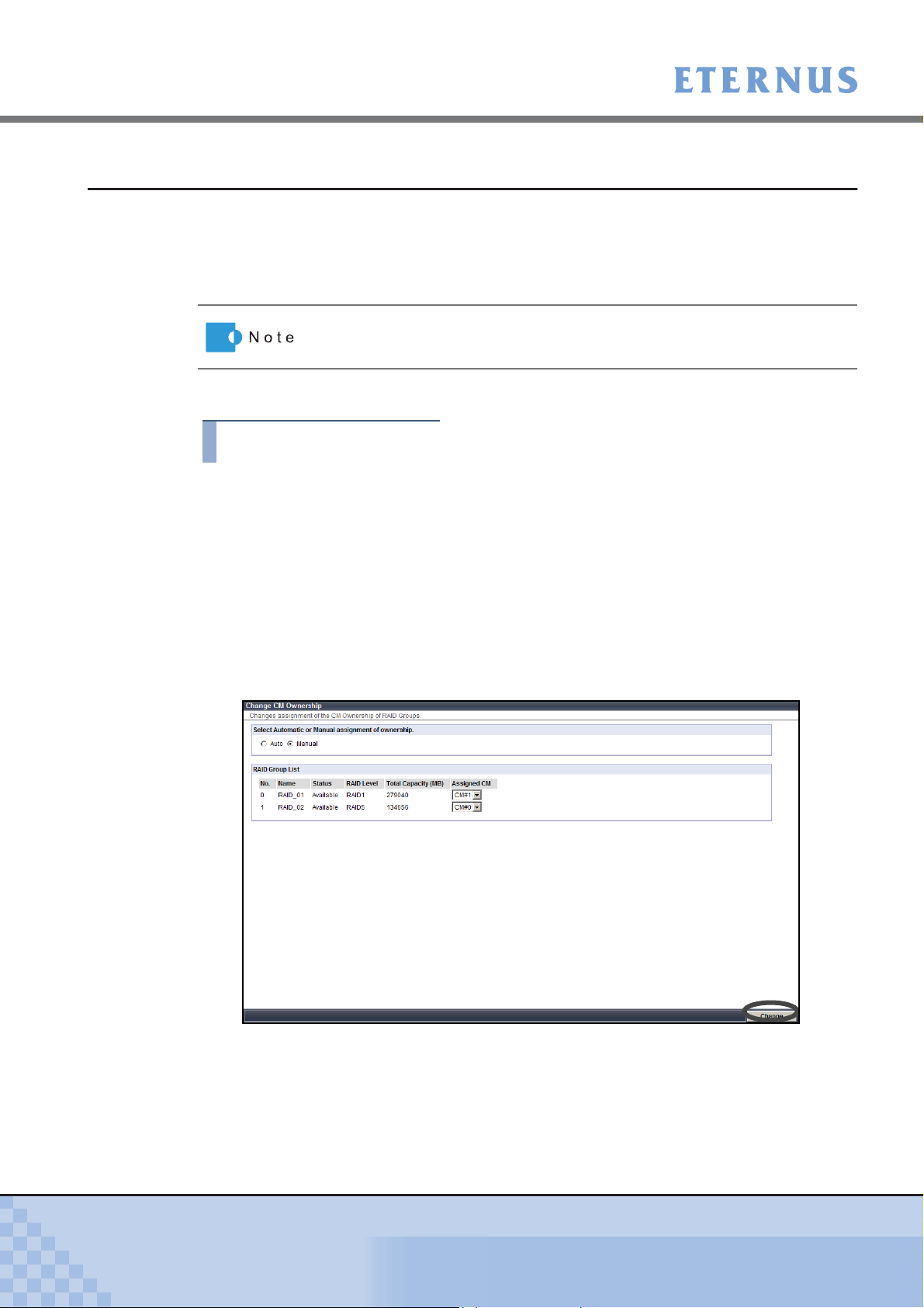
Chapter 5 Configuration
> 5.2 RAID Group Management
5.2.8 Change CM Ownership
The [Change CM Ownership] function changes the assigned CM specified when creating the
RAID group.
Usually, the assigned CM is automatically allocated. If the load is not balanced evenly between
CMs, the assigned CMs can be manually allocated to balance the load.
The procedure to change RAID group assigned CM is as follows:
Procedure
1 Click the [Change CM Ownership] under the [RAID Group Management] menu
on the [Volume Settings] tab.
→ The [Change CM Ownership] screen appears.
When the ETERNUS DX60/DX80 has only one CM, the assigned CM
cannot be changed.
2 Specify the following items, and click the [Change] button.
• Select Automatic or Manual assignment of ownership.
Select the method for assigning the CM from "Auto" or "Manual".
If changing the current setting, a confirmation screen appears.
• RAID Group List
When selecting the "Manual" for "Select Automatic or Manual assignment of
ownership." field, specify the assigned CM for the RAID group.
P2X0-0700-02ENZ0
→ A confirmation screen appears.
ETERNUS DX60/DX80 Web GUI User Guide
91
Copyright 2009 FUJITSU LIMITED
Page 92

Chapter 5 Configuration
> 5.2 RAID Group Management
3 Click the [OK] button.
→ The assigned CM is changed.
End of procedure
P2X0-0700-02ENZ0
ETERNUS DX60/DX80 Web GUI User Guide
92
Copyright 2009 FUJITSU LIMITED
Page 93

Chapter 5 Configuration > 5.3 Volume Management
5.3 Volume Management
The following settings are available as the volume management.
• Create/Delete Volume
• Format Volume
• Encrypt Volume
• LUN Concatenation
• RAID Migration
• Initialize Snap Data Volume
• Release Reservation
• Set Volume Name
• Configure LUN Mapping
5.3.1 Create Volume
The [Create Volume] function creates the volumes in the existing RAID group.
Open or Snap Data Volume (SDV) can be created with this function. After completing the volume
creation, the new volumes are formatted automatically.
Volumes can be accessed from the host when created in the RAID group and LUN mapped.
● The maximum number of volumes that can be registered
The following table shows the maximum number of volumes can be created for each device.
Device Type per RAID group per Device
ETERNUS DX60 Up to 128 Up to 512
ETERNUS DX80 Up to 128 Up to 1,024
• When the maximum number of volumes has already been created in the
ETERNUS DX60/DX80, more volumes cannot be created. In this case,
to create a new volume, first delete volumes using the "5.3.2 Delete Vol-
ume" (page 96) function, and then try creating a new volume again.
• A volume is allocated to uninterrupted free space in the order of
creation.
If an area with the necessary capacity cannot be acquired from the free
space available, use the "5.3.5 LUN Concatenation" (page 101)
to concatenate multiple spaces into a volume.
SDV is the Snap Data Volume that is required for SnapOPC+. Refer to
"5.4.2 Manage Copy Session" (page 129)
for details about SnapOPC+.
function
P2X0-0700-02ENZ0
ETERNUS DX60/DX80 Web GUI User Guide
93
Copyright 2009 FUJITSU LIMITED
Page 94

Chapter 5 Configuration
> 5.3 Volume Management
The procedure to create a volume is as follows:
Procedure
1 Click the [Create Volume] under the [Volume Management] menu on the
[Volume Settings] tab.
→ The [Create Volume] screen appears.
2 Select the RAID group where the volumes are created from the tree in the left of
the screen, or RAID Group List.
→ The detailed information of the selected RAID group is displayed.
3 Specify the following items, and click the [Create] button.
• Volume Name
Enter the volume name between 1 to 16 alphanumeric characters and symbols
(including blanks).
• Type
Select the volume type (Open or SDV).
• Capacity (MB)
Specify the volume capacity to be created in units of MB.
Set the value between 24 to 8,388,607 (MB), or the maximum capacity of the RAID
group.
When creating an SDV, the total SDV capacity (MB) and 0.1% of the
copy source volume capacity is secured in the ETERNUS DX60/
DX80. 0.1% of the copy source volume is the capacity used for the
controlling information area in the SDV.
• Source Volume Capacity (MB) (SDV only)
Specify the total capacity of the copy source for SDV in units of MB.
P2X0-0700-02ENZ0
ETERNUS DX60/DX80 Web GUI User Guide
94
Copyright 2009 FUJITSU LIMITED
Page 95

Chapter 5 Configuration
> 5.3 Volume Management
• Encryption
Select whether to "Enable" or "Disable" encryption mode for the new volume.
An encrypted volume cannot be changed to non-encrypted volumes.
Refer to "5.3.4 Encrypt Volume" (page 99) for details.
• Number of Volumes
When creating multiple volumes of the same type and capacity, set the number of
volumes to be created. All the volumes are created with the same name. Change the
volume names as required (Refer to
"5.3.9 Set Volume Name" (page 111)).
→ A confirmation screen appears.
4 Click the [OK] button.
→ The volumes are created.
End of procedure
P2X0-0700-02ENZ0
ETERNUS DX60/DX80 Web GUI User Guide
95
Copyright 2009 FUJITSU LIMITED
Page 96

Chapter 5 Configuration
> 5.3 Volume Management
5.3.2 Delete Volume
The [Delete Volume] function deletes the volumes in the RAID group.
Make sure to backup any necessary data before proceeding.
• The following volumes cannot be deleted.
- Volumes that are allocated to a Host Affinity or mapped LUN.
- Volumes during RAID migration.
- Copy source and destination volumes during Advanced Copy
session.
- Volumes in the RAID group during Logical Device Expansion.
• A volume is allocated to uninterrupted free space in order of creation.
When a volume is deleted, the space where the volume existed
becomes free space. By repeating creation and deletion of volumes,
free space may be dispersed in the RAID group.
• Up to 128 volumes can be deleted at once.
The procedure to delete a volume is as follows:
Procedure
1 Click the [Delete Volume] under the [Volume Management] menu on the
[Volume Settings] tab.
→ The [Delete Volume] screen appears.
2 Select the volume to be deleted from the "Volume List" field (multiple selections
can be made), and click the [Delete] button.
P2X0-0700-02ENZ0
→ A confirmation screen appears.
ETERNUS DX60/DX80 Web GUI User Guide
96
Copyright 2009 FUJITSU LIMITED
Page 97

Chapter 5 Configuration
> 5.3 Volume Management
3 Click the [OK] button.
→ The selected volumes are deleted.
5.3.3 Format Volume
The [Format Volume] function is used to format (clear data in) the selected volume.
End of procedure
• If selecting and formatting a volume that is in use, the data stored in the
volume will be deleted.
• For a newly created volume, formatting with this function is not required.
Newly created volumes are formatted automatically.
• The following volumes cannot be formatted.
- Volumes with a status other than "Readying" or "Available"
- Volumes in the RAID group during Logical Device Expansion
- Volumes for which Advanced Copy is being performed
- Volumes during RAID migration
Progress of formatting can be checked from the [Volume Status] menu on
the [Status] tab.
The procedure to format a volume is as follows:
Procedure
1 Click the [Format Volume] under the [Volume Management] menu on the
[Volume Settings] tab.
→ The [Format Volume] screen appears.
P2X0-0700-02ENZ0
ETERNUS DX60/DX80 Web GUI User Guide
97
Copyright 2009 FUJITSU LIMITED
Page 98

Chapter 5 Configuration
> 5.3 Volume Management
2 Select the volume to be formatted from the tree in the left of the screen, or
"Volume List" field (multiple selections can be made), and click the [Format]
button.
→ A confirmation screen appears.
3 Click the [OK] button.
→ The selected volumes are formatted.
End of procedure
P2X0-0700-02ENZ0
ETERNUS DX60/DX80 Web GUI User Guide
98
Copyright 2009 FUJITSU LIMITED
Page 99

Chapter 5 Configuration
> 5.3 Volume Management
5.3.4 Encrypt Volume
The [Encrypt Volume] function encrypts the data in the disks to prevent the data leakage caused
by theft or loss when removing disks.
• When encrypting volumes, enable the encryption mode using the "6.4.3
Setup Encryption Mode" (page 187) function. However, when the "Setup
Encryption Mode" is not displayed in the menu, the encryption function
is not available. However, when the encryption function is not available,
the "Setup Encryption Mode" is not displayed in the menu.
• This function prevents data leakage from removal of disks. Therefore,
when accessing from the server, data in the disks is not encrypted. Note
that this function cannot prevent data leakage by server access.
• Once a volume has been encrypted, it cannot be changed back to a
non-encrypted volume.
• Canceling volume encryption is not possible.
• This function cannot be used under the following conditions:
- Encryption mode is not set (refer to "6.4.3 Setup Encryption Mode"
(page 187))
- A warning status component exists in the controller enclosure
- There is no volume to be encrypted
• Volumes in the following conditions cannot be selected as an encryption
target volume (not displayed in the Volume List).
- Volumes which are not in normal status (Rebuilding/Copybacking,
etc.)
- Volumes which are being formatted
- Volumes in RAID migration operation
- Volumes in a RAID group in which Logical Device Expansion is being
executed
- Volumes which are already encrypted
- Volumes which are being encrypted
• When encrypting Advanced Copy target volumes, both the copy source
and copy destination volumes must be encrypted.
• The following performance may be degraded for encrypted volumes
compared with non-encrypted volumes.
- Access to the encrypted volumes
- Copy transfer of encrypted volumes
P2X0-0700-02ENZ0
The progress of an encryption operation can be checked from [Volume
Status] menu on the [Status] tab screen.
ETERNUS DX60/DX80 Web GUI User Guide
99
Copyright 2009 FUJITSU LIMITED
Page 100

Chapter 5 Configuration
> 5.3 Volume Management
The procedure to encrypt a volume is as follows:
Procedure
1 Click the [Encrypt Volume] under the [Volume Management] menu on the
[Volume Settings] tab.
→ The [Encrypt Volume] screen appears.
2 Select the volume to be encrypted from the tree in the left of the screen or
"Volume List" field (multiple selections can be made), and click the [Encrypt]
button.
→ A confirmation screen appears.
3 Click the [OK] button.
→ The selected volume is encrypted.
End of procedure
P2X0-0700-02ENZ0
ETERNUS DX60/DX80 Web GUI User Guide
100
Copyright 2009 FUJITSU LIMITED
 Loading...