

Page 1

T101-1737-01EN 01
IP-9500 series
DVB-S/S2 Modulator card
User’s Guide
Page 2

(This page is intentionally left blank)
Page 3
USING DVB-S/S2 OPTIONAL CARD SAFELY
Handling of This Manual
The manual contains important information regarding the safe use of DVB-S/S2 optional card. Read
it thoroughly before operating this device. Make sure that users of the device read and understand
thoroughly all safety precautions contained in the manual. Keep this manual in a safe and convenient
location for quick reference.
Fujitsu makes every effort to prevent users and bystanders from injury and to prevent property damage.
To ensure no harm to you and bystanders, and to prevent damage to the device itself, be sure to use
DVB-S/S2 optional card in accordance with instructions
in the manual.
The following notice is for USA users only.
DVB-S/S2 optional card has been tested and found to comply with the limits for a Class A digital
device, pursuant to Part 15 of the FCC Rules. These limits are designed to provide reasonable
protection against harmful interference when the equipment is operated in a commercial environment.
This equipment generates, uses, and can radiate radio frequency energy and, if not installed and used in
accordance with the instruction manual, may cause harmful interference to radio communications.
Operation of this equipment in a residential area is likely to cause harmful interference in which case
the user will be required to correct the interference at his own expense.
The following notice is for Canada users only.
This Class A digital apparatus meets all requirements of the Canadian Interference-Causing Equipment
Regulations.
The following notice is for EU (European Union) users only.
This is Class A product of Electromagnetic Interference (EMI) standard. In a domestic environment
this product may cause radio interference in which case the user may be required to make adequate
measures.
This manual includes technology controlled under the Foreign Exchange and Foreign Trade Control
Law of Japan. The manual or a portion thereof must not be exported (or re-exported) without
authorization from the appropriate governmental authorities in accordance with the above law.
DVB- S/S2 optional card is designed and manufactured for use in standard applications such as office
work, personal devices, and household appliances. The product is not intended for special uses (such
as nuclear-reactor control in atomic energy facilities, aeronautic and space systems, air traffic control,
operation control in mass transit systems, medical devices for life support, and missile firing controls in
weapons facilities) where particularly high reliability requirements exist, where the pertinent levels of
safety are not guaranteed, or where a failure or operational error could threaten a life or cause physical
injury (hereafter referred to as "mission-critical" use). Customers considering use of this product for
mission-critical applications must have safety-assurance measures in place beforehand. Moreover,
they are requested to consult our sales representative before embarking on such specialized use.
Copying of and disassembly, decompilation and other forms of reverse engineering of any program
included with this device is prohibited.
Microsoft, Windows, Windows NT, Windows 2000, and Windows XP are registered trademarks or
trademarks of Microsoft Corporation in the United States and/or other countries.
DVB-S/S2 Modulator Card
i
Page 4

IMPORTANT NOTE TO USERS
READ THE ENTIRE MANUAL CAREFULLY BEFORE USING THIS PRODUCT.
INCORRECT USE OF THE PRODUCT MAY RESULT IN INJURY OR DAMAGE TO
USERS, BYSTANDERS OR PROPERTY.
While FUJITSU has sought to ensure the accuracy of all information in this manual, FUJITSU
assumes no liability to any party for any damage caused by any error or omission contained in this
manual, its updates or supplements, whether such errors or omissions result from negligence, accident,
or any other cause. In addition, FUJITSU assumes no liability with respect to the application or
use of any product or system in accordance with descriptions or instructions contained herein; including
any liability for incidental or consequential damages arising therefrom.
FUJITSU DISCLAIMS ALL WARRANTIES REGARDING THE INFORMATION
CONTAINED HEREIN, WHETHER EXPRESSED, IMPLIED, OR STATUTORY.
FUJITSU reserves the right to make changes to any products described herein without
further notice
and without obligation.
No part of this manual shall be reproduced in any way or form without the permission of Fujitsu
Limited.
All Rights Reserved. Copyright
©
FUJITSU LIMITED 2009
DVB-S/S2 Modulator Card
ii
Page 5

PREFACE
Thank you for purchasing the DVB-S/S2 optional card.
This card is the optional card of IP-9500 series that uses H.264 high video compression technology. By
selecting the software type, IP-9500 series operates as the encoder to output video stream or the decoder to
input it through DVB-S/S2 interface.
This product works as the optional card of IP-9500 series and cannot work in stand alone.
This manual is intended for system designers and system managers who use IP-9500 series. Readers are
assumed to have a basic knowledge of networks and video distribution.
April 2009 1st Edition
Product operating environment
Designed for use in real-time audio/video transmission systems and in the transmission system of
monitoring systems,
IP-9500 series is intended for indoor use.
Note:
The contents of this manual are subject to change without notice.
DVB-S/S2 Modulator Card
iii
Page 6

ORGANIZATION AND CONTENTS OF THIS MANUAL
The manual consists of four chapters.
Read Chapters 1 to 4 first for information on installing and connecting the device.
Read Software User’s Guide for the operation and management.
Chapter 1 Preparations
This chapter describes the checks that are required before the start of operation.
Chapter 2 Installation and Connection
This chapter describes conditions for installation and explains how to connect it to peripheral devices.
Chapter 3 Cable and Optional Card Specifications
This chapter contains a type of how work is implemented, cable connection system diagrams,
and cable connector details.
Chapter 4 In Case of Trouble
This chapter describes the actions to be taken if the card does not operate normally..
DVB-S/S2 Modulator Card
iv
Page 7
WARNING INDICATIONS
This manual uses warning indications to warn of conditions in order to prevent serious injury and
property damage. Warning indications consist of warning markings of specific levels and warning
messages. The warning markings are shown below along with their definitions.
WARNING indicates a situation that could lead to serious injury
or loss of life if procedures are not followed correctly.
CAUTION indicates a situation that could lead to
minor or
moderate injury and/or damage to the device itself if procedures
are not followed correctly.
!
CAUTION
Warning indications within text
Warning markings are followed by warning messages. Every warning marking is centered on a line.
Left and right indents are set for warning messages to differentiate them from ordinary text.
Furthermore, the lines immediately before and after warning indications are left blank.
DVB-S/S2 Modulator Card
v
Page 8
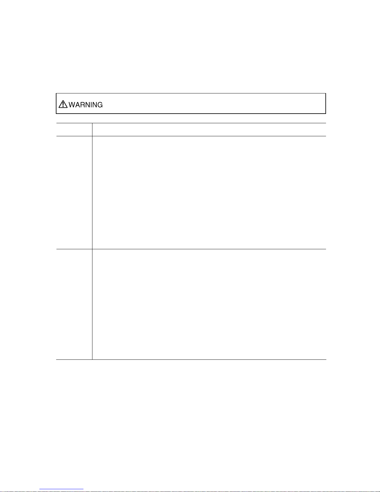
SAFETY PRECAUTIONS
List of important warnings
The table below contains a list of important warning indications.
Indicates a situation that could lead to serious injury or loss of life if procedures
are not followed correctly.
Work type Warning
Normal use Possibility of electric shock and fire
If an excessive heat, smoke, an abnormal odor or an unusual noise is coming from the
device, immediately set its power switch to OFF and remove the power cord plug from
the power receptacle. Then, contact a Fujitsu Service Center.
This indicates a hazardous situation that could lead to fire and electric shock.
Possibility of electric shock and fire
If foreign matter (e.g., water, bits of metal, fluid) gets inside the device, immediately set
its power switch to OFF and remove the power cord plug from the power receptacle.
Then, contact a Fujitsu Service Center.
This indicates a hazardous situation that could lead to fire and electric shock.
Possibility of electric shock and fire
The presence of foreign matter such as water inside the device creates a hazardous
situation that could lead to fire and electric shock.
Installation
Possibility of electric shock and fire
Do not install the device in the following places because using it there may cause a fire or
electric shock:
Extremely dusty or dirty place
Wet or humid location
Hot location, such as a place where the device is exposed to direct sunlight or is
near heating equipment
Near products (e.g., speakers) that generate a strong magnetic field
Location where the temperature is too hot or cold
In an environment with sharp temperature fluctuations
Area with poor ventilation
Near a fire
DVB-S/S2 Modulator Card
vi
Page 9

Work type Warning
Installation
and
relocation
Possibility of serious injury and damage to the device
Do not install the device in places where it is exposed to shock and strong vibrations, on
an incline or in unstable locations.
This indicates a hazardous situation that could lead to serious injury or damage to the
device.
Possibility of serious injury and damage to the device
When relocating the device, observe the following precautions to protect against serious
injury and damage to the device:
Set the power switch to OFF, and disconnect all connected cables. Take care to
avoid getting your feet entangled in the cables.
To prevent serious personal injury when moving the device, take special care to pay
attention to your surroundings.
DVB-S/S2 Modulator Card
vii
Page 10
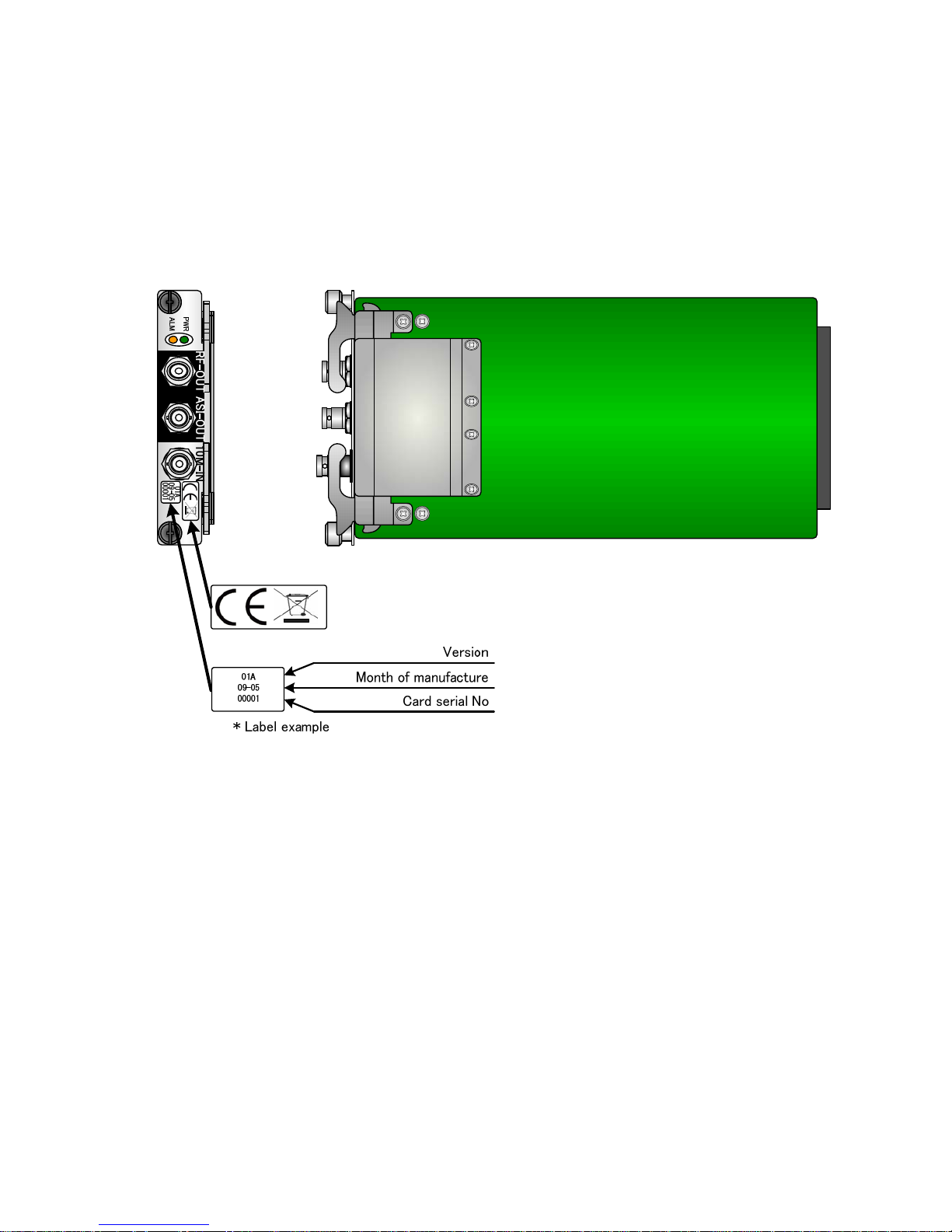
LABEL
The warning label shown below is affixed to the device.
・ Never remove the label.
・ Be sure to check the label at the bottom of this device before coming to the power supply.
・ The following label is intended for users of the devices.
DVB-S/S2 Modulator Card
viii
Page 11
PRODUCT HANDLING PRECAUTIONS
Maintenance
WARNING
CAUTION
Do not try to repair the device yourself. Contact a Fujitsu Service
Center.
Read this manual thoroughly before attempting to operate the device.
If you have any questions, contact a Fujitsu Service Center.
If a problem occurs, contact a Fujitsu Service Center.
The Fujitsu Service Center will ask you to describe the problem, the lamp display status of
alarm LEDs and other details. Check the system for this information.
Connectable devices
Only devices that conform to the device interface specifications (see Appendix 2.3, "Device
Specifications") can be connected. Otherwise, if incompatible devices are connected, the result
may be personal injury and property damage.
Disposal
To dispose of the device, contact a Fujitsu Service Center, or request a specialist to take care its
disposal.
Modification and restoration
Do not use any device that has been modified or rebuilt with refurbished used parts. Doing so
may result in personal injury and property damage.
DVB-S/S2 Modulator Card
ix
Page 12

DVB-S/S2 Modulator Card
x
(This page is intentionally left blank)
Page 13

CONTENTS
USING DVB-S/S2 OPTIONAL CARD SAFELY............................... i
PREFACE.........................................................iii
ORGANIZATION AND CONTENTS OF THIS MANUAL......................... iv
WARNING INDICATIONS............................................... v
SAFETY PRECAUTIONS............................................... vi
LABEL ......................................................... viii
PRODUCT HANDLING PRECAUTIONS....................................iix
Chapter 1 Preparations ...................................................................1
1.1 Main Features ................................................ 3
1.2 Components ................................................. 4
1.3 Part Names .................................................. 5
Chapter 2 Installation and Connection...........................................7
2. 1 Installation ................................................... 9
2.1.1 Environment Conditiion................................. 9
2.2 Insertion and Removal........................................ 10
2.3 Connection to Modulator Card ................................. 11
2.3.1 Connection to Up-Converter Device..................... 11
2.3.2 Connection to DVB-ASI Input Device .................... 12
2.3.3
Connection to External 10MHz Reference Signal Generator ....... 13
Chapter 3 Cable and Optional Card Specifications ......................15
3.1 Installation Preparations ...................................... 17
3.2 Cable and Connector Details .................................. 18
3.3 Function Specifications ....................................... 20
3.3.1 External Specifications............................... 20
3.3.2 Environmental Specifications.......................... 20
3.3.3 Indicators............................................ 20
3.3.4 Equipment Specifications.............................. 21
3.3.5 Specifications........................................ 23
3.4 Appearance ................................................. 26
Chapter 4 In case of Trouble..........................................................27
4.1 Troubleshooting Information................................... 29
I
Page 14

II
(This page is intentionally left blank)
Page 15

Capter 1 Preparations
CHAPTER 1
PREPARATIONS
This chapter describes the checks that are required before the start of IP-9500
series operation.
1.1 Main Features···················································3
1.2 Components······················································ 4
1.3 Part Names ·······················································5
Page 16

The operation method is not described in this user’s guide. See the software
user’s guide.
Page 17

Chapter1 Preparations
DVB-S/S2 Modulator Card
3
1.1 Main Features
1.1
This DVB-S/S2 card is one of optional cards of IP-9500 series, Fujitsu video transmission unit with
H.264 latest encoding technology. This card operates with IP-9500 series main component and
IP-9500 series software and can transmit the HD (High Definition) video and audio signal in real time.
Main Features
Item Specifications
BNC connector x 1 (Card for IF band)
RF output 1 ch
F connector x 1 (Card for L band)
DVB-ASI output 1 ch BNC connector x 1
Interfaces
External 10MHz reference
signal input
1 ch BNC connector x 1
Installation
conditions
The card is mounted in a slot for an optional card in the IP-9500 series device.
The installation conditions are the same as for other IP-9500 series devices.
Dimensions W: 118.62; H: 25.7; D: 239 (mm) 0.2 (mm)
Weight 0.5 kg, maximum
Power
consumption
15 W or less
Temperature
humidity
Temperature: -10 to +55C * Except for low-temperature startup at less than 0C
Humidity: 20 to 90% RH (No condensation)
(Conditions for guarantee of proper operation and characteristics)
Page 18

Chapter1 Preparations
DVB-S/S2 Modulator Card
4
1.2 Components
1.2
The DVB-S/S2 optional card consists of the following components. The cable is supposed to procure
separately.
- DVB-S/S2 Modulator Card: 1 pcs
Page 19

Chapter1 Preparations
DVB-S/S2 Modulator Card
5
1.3 Part Names
1.3
This section gives the name and describes the function of individual parts of DVB-S/S2 optional card.
The figure below shows the layout of parts on the outside of the device, and the table below lists the
name and describes the function of individual parts.
Figure IP-9500 series Rear Panel
Part names
No. Name (as indicated) Description
(1)
Screws
Screws for securing the DVB-S/S2 modulator card in an
optional-card slot of this device in the IP-9500 series
(2)
Levers
Levers used to insert the DVB-S/S2 modulator card into or remove
it from optional-card slot of this device in the IP-9500 series
(3)
Power LED lamp
(PWR)
Lamp that goes on when the power to the card is turned on
(4)
Alarm LED lamp
(ALM)
Lamp that goes on if the card has an error
(5)
Radio frequency output connector
(RF-OUT)
Terminal for radio frequency output. Its unbalanced output is 75Ω.
The output radio frequency and connector are either the IF-band
frequency/BNC connector or L-band frequency/F connector,
depending on the type of optional card that you purchased.
For details about the cable connection, see Section 2.3.1,
"Connection to Up-Converter Device."
For details about the specifications, see "Radio frequency output" in
Section 3.3.4, "Equipment Specifications."
(6)
DVB-ASI output connector
(ASI-OUT)
Terminal for DVB-ASI output. It is a BNC connector, and its
unbalanced output is 75Ω.
For details about the cable connection, see Section 2.3.2,
"Connection to DVB-ASI Input Device."
For details about the specifications, see "DVB-ASI output x 1" in
Section 3.3.4, "Equipment Specifications."
Page 20

Chapter1 Preparations
DVB-S/S2 Modulator Card
6
(7)
External 10MHz reference signal
input connector
(10 M-IN)
Terminal for external 10MHz reference signal input. It is a BNC
connector, and its unbalanced input is 50Ω.
The input is mainly used for frequency synchronization with other
radio devices .
If you do not require synchronization, no input is necessary because
the IP-9500 series can operate with the internal 10MHz reference
signal on the card.
For details about the cable connection, see Section 2.3.3,
"Connection to External 10MHz Reference Signal Device."
For details about the specifications, see "External 10MHz reference
signal input x 1" in Section 3.3.4, "Equipment Specifications."
Page 21

Chapter 2 Installation and Connection
CHAPTER 2
INST ALLATION AND
CONNECTION
This chapter describes conditions for installation and explains how to connect it to
peripheral devices.
2.1 Installation························································· 9
2.2 Insertion and Removal···································· 10
2.3 Connection to Modulator Card ························ 11
Page 22

Injury
The cables connected to this card should be fixed on rack or floor. Otherwise,
it may cause the unexpected trouble.
Page 23

Chapter 2 Installation and Connection
DVB-S/S2 Modulator Card
9
2. 1 Installation
2.1
Installation requirements of the DVB-S/S2 modulator card are shown below.
2.1.1 Environment Conditiion
Please use this card in the environment for the suction temperature of the IP-9500
series device and the ambient temperature of the device not to exceed 55 [degree].
However it causes the breakdown and the card longevity to become outside the operation guarantee
range when used under the environment that comes off from the above-mentioned condition, and to be
shortened remarkably.
Moreover, please use it after observing the installation requirements also reading the manual of the
IP-9500 series devices.
Please refer to “3.3.2 environmental specification” for detailes of an environmental specification.
Page 24

Chapter 2 Installation and Connection
2.2 Insertion and Removal
2.2
The install procedure of DVB-S/S2 optional card is as follows.
Turn off the power of IP-9500 series when the insertion and removal of DVB-S/S2 optional
card.
③ Insert the card along the guide rail of device
opening the two levers, and then close the two
levers simultaneously after the card reaches
the end.
④ Tighten two screws to fix the card
*> To remove this cars,reverse the order above
② Remove blank panel
D
Figure DVB-S/S2 Modulator Card Insertion and Removal
DVB-S/S2 Modulator Card
10
Page 25

Chapter 2 Installation and Connection
DVB-S/S2 Modulator Card
11
2.3 Connection to Modulator Card
2.3
This section describes how to connect with the DVB-S/S2 Modulator card.
2.3.1 Connection to Up-Converter Device
When IP-9500 series operates with the encoder mode and also with the DVB-S/S2 mode, the
cable is connected to “RF-OUT” on the DVB-S/S2 modulator card as shown in the figure below.
- In the case of DVB-S/S2 IF band modulator card, please use the BNC cable.
- In the case of DVB-S/S2 L band modulator card, please use the F cable.
For details about connectors and cables, see Section 3.2, “Cable and Connector Details.”
NOTE:
For electrical specifications, see Section 3.3, “Function Specifications.”
PUSH
PUSH
Up converter
BNC/P 75[Ohm]Cable
(IF Band)
F/P 75[Ohm]Cable
(L Band)
Figure Connection to UpConverter Device
Page 26

Chapter 2 Installation and Connection
2.3.2 Connection to DVB-ASI Input Device
When IP-9500 series operates with the encoder mode, the BNC cable is connected to
“ASI-OUT” on the DVB-S/S2 modulator card as shown in the figure below.
For details about connectors and cables, see Section 3.2, “Cable and Connector Details.”
NOTE:
For electrical specifications, see Section 3.3, “Function Specifications.”
PUSH
PUSH
DVB-ASI
BNC/P 75[Ohm]Cable
Figure Connection to DVB-ASI Input Device
DVB-S/S2 Modulator Card
12
Page 27

Chapter 2 Installation and Connection
DVB-S/S2 Modulator Card
13
2.3.3 Connection to External 10MHz Reference Signal
Generator
When IP-9500 series operates with the encoder mode and also with the DVB-S/S2 mode, the
BNC cable is connected to “10M-IN” on the DVB-S/S2 modulator card as shown in the figure below.
This external 10MHz reference signal input is mainly used for frequency synchronization with
other radio devices.
If you do not require the synchronization, no input is necessary because the
IP-9500 series can operate with the internal 10MHz reference signal on the DVB-S/S2 modulator card.
For details about connectors and cables, see Section 3.2, “Cable and Connector Details.”
NOTE:
For electrical specifications, see Section 3.3, “Function Specifications.”
PUSH
PUSH
External 10MHz reference
Signal generator
BNC/P 50[Ohm]Cable
Figure Connection to External 10MHz Reference Signal Generator
Page 28

Chapter 2 Installation and Connection
DVB-S/S2 Modulator Card
14
(This page is intentionally left blank)
Page 29

Chapter 3 Cable and Optional Card Specifications
CHAPTER 3
CABLE AND OPTIONAL CARD
SPECIFICATIONS
This chapter contains a type of how work is implemented, cable connection system
diagrams, and cable connector details
3.1 Installation Preparations·································· 17
3.2 Cable and Connector Details ··························18
3.3 Function Specifications····································20
3.4 Appearance·····················································26
Page 30

(This page is intentionally left blank)
Page 31

Chapter 3 Cable and Optional Card Specification
3.1 Installation Preparations
3.1
A type of IP-9500 series installation work is shown below.
When constructing a system that uses IP-9500 series, consideration must be given so that its
boundary between IP-9500 series and other devices is similar to that shown in the above figure.
The type of work may change depending on the system.
DVB-S/S2 Modulator Card
17
Page 32

Chapter 3 Cable and Optional Card Specification
3.2 Cable and Connector Details
3.2
(1) RF Output cable
IF-Band
L-Band
DVB-S/S2 Modulator Card
18
Page 33

Chapter 3 Cable and Optional Card Specification
(2) DVB-ASI
Output cable
Coaxial cable 75Ω
BNC/Male BNC/Male
SIGNAL
SG
SIGNAL
SG
①
②
①
②
DVB-ASI 100 m ( Coaxial cable 75Ω S-5C-FB or more )
Coaxial cable with BNC connector
<Modulator
Card>
<External
device>
Front view
Connector
Order
Maximum length
(S-5C-FB or more)
1
2
(3) External 10MHz Reference Signal Input cable
Coaxial cable 50Ω
BNC/Male BNC/Male
SIGNAL
SG
SIGNAL
SG
①
②
①
②
N.A., Refer to 3.3.4「Specification」External 10MHz Reference
Signal Specification
(Coaxial cable 50Ω 5D-2V or more)
Coaxial cable with BNC connector
<Modulator
Card>
<External
device>
Front view
Connector
Order
Maximum length
(5D-2V or more)
1
2
DVB-S/S2 Modulator Card
19
Page 34

Chapter 3 Cable and Optional Card Specification
3.3 Function Specifications
3.3
3.3.1 External Specifications
The table below lists the external specifications of the card.
Item Specifications
Installation
conditions
Mounted in a slot for optional card in this device in IP-9500 series
Dimensions W: 118.62; H: 25.7; D: 239 (mm) 0.2[mm]
Cooling system Forced cooling (using fan of main unit of this device in IP-9500 series)
Power supply (Power supplied from main unit of IP-9500 series)+5.0 V and +3.3 V
Power
consumption
15 W or less
Weight 0.5 kg, maximum
3.3.2 Environmental Specifications
The table below lists the environmental specifications of the card.
Item Specifications
Power
DC+5V+5%/-7% , DC+3.3V±5%
Temperature
and humidity
conditions
Temperature: -10 to 55C * Except for low-temperature startup at less than 0C
Humidity: 20 to 90% (No condensation)
(Conditions for guarantee of proper operation and characteristics)
Temperature
and humidity
conditions
(Non-operating)
Temperature: -10 to 65C
Humidity: 90% or less (No condensation)
Airborne dust Telecommunications equipment room or office environment (0.2 mg/m3 or less)
Electromagnetic
interference
control
Class A information processing equipment
3.3.3 Indicators
The table below lists the indicator specifications of the card.
Item Name Color Specifications Operation
PWR Green Card operating status
OFF: Not operating
ON: Operating normally
LED
indicators
ALM Amber Card error status ON: Card error
DVB-S/S2 Modulator Card
20
Page 35

Chapter 3 Cable and Optional Card Specification
3.3.4 Equipment Specifications
The table below lists the equipment specifications of the card.
Interfaces
Item Specifications
BNC connector x 1 (Card for IF band)
Radio frequency output 1 ch
F connector x 1 (Card for L band)
DVB-ASI output 1 ch BNC connector x 1
Interfaces
External 10MHz reference signal
input
1 ch BNC connector x 1
The tables below list the equipment specifications of the above interfaces.
Radio frequency output
IF-band radio frequency output x 1 (Card for IF band)
Name Specifications Remarks
Radio
frequency
output
(IF band)
Frequency: 50 to 90 or 100 to 180 MHz, 1 KHz interval
Connection: AC coupling
Output impedance: 75Ω (Unbalanced)
Output level: -30 to -10 dBm, 0.1 dB interval
Silk-screened
label
RF-OUT Connector type BNC (Female)
Pin No. Signal name Remarks
1
2
SIGNAL
SG
-
-
2
1
L-band radio frequency output x 1 (Card for L band)
Name Specifications Remarks
Radio
frequency
output
(L band)
Frequency: 950 to 1750 MHz, 1 KHz interval
Connection: AC coupling
Output impedance: 75Ω (Unbalanced)
Output level: -30 to -10 dBm, 0.1 dB interval
Silk-screened
label
RF-OUT Connector type F (Female)
Pin No. Signal name Remarks
1
2
SIGNAL
SG
-
-
2
1
DVB-S/S2 Modulator Card
21
Page 36

Chapter 3 Cable and Optional Card Specification
D
VB-ASI output x 1
Name Specifications Remarks
DVB-ASI
output
Signal format: NRZI
Input impedance: 75Ω (Unbalanced)
Output amplitude: 800 mV10%
-
Silk-screened
label
ASI-OUT Connector type BNC (Female)
Pin No. Signal name Remarks
1
2
SIGNAL
SG
-
-
2
1
External 10MHz reference signal input x 1
Name Specifications Remarks
External
10MHz input
Signal format: Sine Wave
Connection: AC
Input impedance: 50Ω (Unbalanced)
Input level: 0.8 to 1.9 Vrms
Frequency accuracy: Within 30 ppm
Silk-screened
label
10M-IN Connector type BNC (Female)
Pin No. Signal name Remarks
1
2
SIGNAL
SG
-
-
2
1
You can select one reference signal from the following two types of source of reference signals. The
reference signal source is used to generate career, and is used as a reference timing signal of modulation
symbol.
1) Internal 10MHz reference signal source mounted on the card
2) External 10MHz reference signal source
The external 10MHz reference signal source is mainly used for frequency synchronization with external
devices.
DVB-S/S2 Modulator Card
22
Page 37

Chapter 3 Cable and Optional Card Specification
3.3.5 Specifications
The table below lists the card specifications.
Specifications
No. Item Specifications Remarks
1 Transmission
format
CCM (Constant Coding and Modulation)
Inner FEC: Convolutional, K=7
Outer FEC: Reed Solomon, 188/204
DVB-S(DSNG) 2 FEC
Inner FEC: LDPC (Low-Density Parity Check)
Outer FEC: BCH (Bose-Chaudhuri-Hocquengham)
DVB-S2
3 Coded LDPC
block size
(Normal): 64 800 (bits)
(Short) : 16 200 (bits)
DVB-S2
DVB-S(DSNG)
QPSK
1/2, 2/3, 3/4, 5/6, 7/8 EN 300 421
DVB-S(DSNG)
8PSK
2/3, 5/6, 8/9 EN 301 210
DVB-S2
QPSK
1/2, 3/5, 2/3, 3/4, 4/5, 5/6, 8/9,
9/10
DVB-S2
8PSK
3/5, 2/3, 3/4, 5/6, 8/9, 9/10
4 Inner FEC rate
(Inner code
rate)
DVB-S2
16APSK
2/3, 3/4, 4/5, 5/6, 8/9, 9/10
EN 302 307 (V1.1.2)
0.35 (QPSK) DVB-S
EN 300 421
0.35 (QPSK, 8PSK)
0.25 (8PSK)
DVB-S(DSNG)
EN 301 210
5 Roll-off factor
0.35, 0.25, 0.20 for each QPSK, 8PSK, 16APSK DVB-S2
EN 302 307 (V1.1.2)
6 PILOT
SYMBOLS
insertion (Pilot
Mode)
Can be switched on/off.
DVB-S2
7 TS packet length 188 bytes, 204 bytes
8 GOLD CODE
sequence number
0 to 2 ˆ 18-2 (262142)
Gold code sequence index.
DVB-S2 Scrambling
DVB-S/S2 Modulator Card
23
Page 38

Chapter 3 Cable and Optional Card Specification
Specifi
cations No. Item
IF band modulator card L band modulator card
Remarks
9 Transmission
radio frequency
50 to 90 MHz or
100 to 180 MHz
950 to 1750 MHz 1 KHz interval
10 Transmission
frequency
stability
3.0 ppm
With 10MHz reference
signals selected in card
11 Modulation QPSK, 8PSK ------------------ DVB-S(DSNG)
QPSK, 8PSK, 16APSK ------ DVB-S2
12 Symbol rate DVB-S: 2 to 40 Msps ---QPSK
2 to 27 Msps ---8PSK
DVB-S2: 2 to 35 Msps ---QPSK
2 to 28 Msps ---8PSK
2 to 18 Msps ---16APSK
1 sps interval.
The maximum setting
range for each modulation
method is shown on the
left. For details, read the
device software manual.
13 Transmission
power stability
+/- 1.0 dB
14 Output level -30.0 to -10.0 dBm 0.1 dB interval
15 In-band
amplitude
deviation
+/- 0.5 dB
16 In-band group
delay
The card meets the following characteristic:
Section 2.1.3, ETSI / DVB EN series,
Signal spectrum at modulator output
17 Spectrum
characteristic
The card meets the following spectrum characteristic:
Section 2.1.3, ETSI / DVB EN series,
Signal spectrum at modulator output
18 Return loss ≥ 20 dB ≥ 14 dB RF-OUT
19 Modulation
accuracy
≤ 3.0% ≤ 3.0% No modulation (CW)
20 BUC control
N/A
21 BUC power feed
N/A
22 BUC 10M utput
N/A
23 10MHz
reference signal
input
Available
24 Monitoring
function
Total transmission power level
DVB-S/S2 Modulator Card
24
Page 39

Chapter 3 Cable and Optional Card Specification
No. Ite
m Specifications Remarks
25 Testability The following test data transmission can be used for
testing purposes:
- Test data transmission for BER evaluation
PN15-stage or PN23-stage
FEC coding through
Inner FEC: Convolutional
Inner FEC: LDPC (Low-Density Parity Check)
FEC: BCH (Bose-Chaudhuri-Hocquengham)
Scrambling through
Interleaving through
- Unmodulated continuous waves transmission (CW)
26 Latency - DVB-S: 5 ms or less
- DVB-S2: 25 ms or less
TS input to RF output
DVB-S/S2 Modulator Card
25
Page 40

Chapter 3 Cable and Optional Card Specification
3.4 Appearance
3.4
The appearance of this equipment is shown below.
118.62
239
25.7
DVB-S/S2 Modulator Card
26
Page 41

Chapter 4 In case of Trouble
CHAPTER 4
IN CASE OF TROUBLE
This chapter describes the actions to be taken if the card does not operate normally.
4.1 Troubleshooting Information····························29
Page 42

(This page is intentionally left blank)
Page 43

Chapter 4 In Case of Trouble
DVB-S/S2 Modulator Card
29
4.1 Troubleshooting Information
4.1
If the
card is not operating normally, take the corrective action described for the card status in the table
below. For details about the corrective action if the device is not operating normally, see the user's manual
for the device. For details about how to operate the software, see the software manual for the main unit of
this device in the IP-9500 series.
If the card status does not improve even after you take the corrective action, contact a Service Center.
N
o.
Classificat
ion
Status Check contents Corrective action
1
Is the power cable of the
device connected?
Confirm that the power cable is correctly
connected to the power outlet.
2
Is the voltage normal at the
power outlet of the device?
If the power cable of another device is
connected to the same power outlet, check the
operation of the other device.
3
Power supply
The card cannot be
powered on.
(The PWR lamp does
not turn on.)
Is the card securely
inserted?
Referring to Section 2.2, "Insertion and
Removal," confirm that the card is correctly
inserted.
4
Radio
frequency
output
There is no radio
frequency output.
Is the cable connected
normally?
- Referring to Section 2.3.1, "Connection to
Up-Converter Device," confirm that the cable
is correctly connected.
- Confirm that the cable has no breaks in wiring
or other problems.
5
ASI output
There is no ASI
output.
Is the cable connected
normally?
- Referring to Section 2.3.2, "Connection to
DVB-ASI Input Device," confirm that the
cable is correctly connected.
- Confirm that the cable has no breaks in wiring
or other problems.
6
Is the cable connected
normally?
- Referring to Section 2.3.3, "Connection to
External 10MHz Reference Signal Output
Device," confirm that the cable is correctly
connected.
- Confirm that the cable has no breaks in wiring
or other problems.
7
CLK synchronization
A "reference input
break" or "loss of
reference
synchronization"
occurred in an attempt
to use an external
10MHz reference
signal.
Does the external 10MHz
reference signal have the
normal signal quality?
For details about the specifications of the
external 10MHz reference signal that is input,
see "External 10MHz reference signal input" in
Section 3.3.4, "Equipment Specifications."
This problem also may occur when the jitter
characteristic of the external 10MHz reference
signal becomes extremely bad. Therefore, be
sure to use a reference signal with a good jitter
characteristic.
8
Card type
The selection of the
optional-card type has
an error.
Does your device in the
IP-9500 series series have
"Encoder" as the operating
mode?
Use the card with "Encoder" set for the
operating mode of the device.
Page 44

Chapter 4 In Case of Trouble
DVB-S/S2 Modulator Card
30/30
9
Removal
The card was removed
with the device power
on. Then, a related
error occurred.
Does the device start
normally when the card is
correctly inserted and the
power is turned on?
- The card does not support hot plugging. Be
sure that the power to the device is off when
inserting or removing the card.
- If the card does not operate normally, it may
be faulty. Contact a Service Center.
Page 45

D
VB-S/S2 Modulator card
User’s Guide
April, 2009 1st Edition
© FUJITSU LIMITED
If
this manual is missing a page or pages are not in the proper order, it will be replaced.
Page 46

 Loading...