

Page 1
DESKPOWER C600 User’s Manual
Fujitsu endeavours to ensure that the information in this document is correct, but accepts no liability
for any error or omission in the same. Any procedures described in this document for operating Fujitsu
products should be read and understood by the operator before such products are used. To ensure
that Fujitsu products function without risk to safety and health, such procedures should be strictly
observed by the operator. The development of Fujitsu products and services is continuous and
published information may not be up to date. Any particular issue of a product may contain facilities
not described herein. It is important to check the current position with Fujitsu. Specifications and
statements as to performance in this document are Fujitsu estimates intended for general guidance.
They may require adjustment in particular circumstances and should therefore not be taken as formal
offers or commitments.
DESKPOWER is a trademark of Fujitsu Limited. The following are registered trademarks of Microsoft
Corporation: MS, MS-DOS, Windows ® NT, Windows ® 98, Windows Millennium, Window ® 2000 and
Windows XP.
Intel and Pentium are registered trademarks of Intel Corporation in the U.S.
Celeron is a registered trademark of Intel Corporation in the U.S.
Other product names are trademarks or registered trademarks of respective companies.
Other products are copyrighted by individual companies.
All other trademarks referenced are trademarks or registered trademarks of their respective owners,
whose protected rights are acknowledged.
Copyright © Fujitsu PC Asia Pacific
All rights, including rights of translation, reproduction by printing, copying or similar methods, in part
or in whole, are reserved.
Offenders will be liable for damages.
All rights, including rights created by patent grant or registration of a utility model or design, are reserved.
Delivery subject to availability. Right of technical modification reserved.
DECLARATION OF CONFORMITY
according to FCC Part 15 Class B
This device complies with Part 15 Class B of the FCC Rules. Operations are subject to the following
two conditions:
(1) This device may not be allowed to cause harmful interference, (2) This device must accept any
interference received, including interference that may cause undesired operation.
Website: www.pc-ap.fujitsu.com
i
Page 2

Important safety instructions
1. Read these instructions carefully. Save these instructions for future reference.
2. Follow all warnings and instructions marked on the product.
3. Unplug this product from the wall outlet before cleaning. Do not use liquid cleaners or aerosol
cleaners. Use a damp cloth for cleaning.
4. Do not use this product near water.
5. Do not place this product on an unstable cart, stand, or table. The product may fall, causing serious
damage to the product.
6. Slots and openings in the cabinet and the back or bottom are provided for ventilation; to ensure
reliable operation of the product and to protect it from overheating, these openings must not be
blocked or covered. The openings should never be blocked by placing the product on a bed, sofa,
rug, or other similar surface. This product should never be placed near or over a radiator or heat
register, or in a built-in installation unless proper ventilation is provided.
7. This product should be operated from the type of power indicated on the marking label. If you are
not sure of the type of power available, consult your dealer or local power company.
8. This product is equipped with a 3-wire grounding-type plug, a plug having a third (grounding) pin.
This will only plug into a grounding-type power outlet. This is a safety feature. If you are unable to
insert the plug into the outlet, contact your electrician to replace your obsolete outlet. Do not defeat
the purpose of the grounding-type plug.
9. Do not allow anything to rest on the power cord. Do not locate this product where persons will
walk on the cord.
10. If an extension cord is used with this product, make sure that the total ampere rating of the
equipment plugged into the extension cord does not exceed the extension cord ampere rating.
Also, make sure that the total rating of all products plugged into the wall outlet does not exceed
15 amperes.
11. Never push objects of any kind into this product through cabinet slots as they may touch dangerous
voltage points that could result in a fire or electric shock. Never spill liquid of any kind on the product.
12. Do not attempt to service this product yourself, as opening or removing covers may expose you
to dangerous voltage points or other risks. Refer all servicing to qualified service personnel.
ii
Page 3

13. Unplug this product from the wall outlet and refer servicing to qualified service personnel under
the following conditions:
a. When the power cord or plug is damaged or frayed.
b. If liquid has been spilled into the product.
c. If the product has been exposed to rain or water.
d. If the product does not operate normally when the operating instructions are followed. Adjust
only those controls that are covered by the operating instructions since improper adjustment
of other controls may result in damage and will often require extensive work by a qualified
technician to restore the product to normal condition.
e. If the product has been dropped or the cabinet has been damaged.
f. If the product exhibits a distinct change in performance, indicating a need for service.
14. Use only the proper type of power supply cord set (provided in your accessories box) for this unit.
It should be a detachable type: UL listed/CSA certified, BS1363, ASTA, SS145 certified, rated
10A 250V minimum, VDE approved or its equivalent. Maximum length is 15 feet (4.6 meters).
15. NOTE:
Please take extra precaution when connecting the LAN cable; do not connect the LAN cable
to the peripheral device’s connector, that might have excessive voltage.
iii
Page 4
Before reading this manual
This section describes safety precautions and convention used in this manual. Be sure to read this.
For Safe Operation
This manual contains important information for using the DESKPOWER personal computer.
Read this manual thoroughly before using your PC. In particular, “Safety Precautions” in this manual
must be read and understood.
This manual including “Safety Precautions” must be readily available at all times.
This equipment is compliant with the PC industry standard (PC-11-1988) of the Japan Electronics
and Information Technology Industries Association.
Note
This product is a Class B Information Technology Equipment and conforms to the standard set by
the Voluntary Control Council for Interference by Technology Equipment (VCCI).This product is
designed to be used in a domestic environment, however, it may cause radio interference when
used in the vicinity of a radio or television receiver.
Make sure that you read the manual when using this product.
Fujitsu, as a member of the International Energy Star Program, recognizes that
this equipment is compliant with the standard of the International Energy Star
Program.
The International Energy Star Program is a worldwide program for promoting
energy saving for computers and other office equipment. The program aims at
promoting the development and use of products equipped with the functions that can effectively
reduce energy consumption and uses a voluntary system that allows enterprises to join at their
own discretion. The target products are office equipment including computers, displays, printers,
facsimiles, and copying machines. The standards for individual types of equipment and the mark
( ) prepared by the Program are used commonly among member countries.
Caution
This equipment is class B information technology equipment based on the standard of the Voluntary
Control Council for Interference by Information Technology Equipment (VCCI). Although the
equipment is intended for use in residential environments, it may create interference if placed near
radio or television.
Handle the equipment in accordance with the manual.
iv
Page 5
Using this Product for High-Safety Applications
This product is for office, personal, home, ordinary industry and other general use. It is not designed
and manufactured for use in high-safety applications.
Do not use this product for such applications without taking measures to satisfy the high-safety
requirements.
High-safety applications require extremely high level of safety, and involve serious hazards to life
and health if the required safety is not assured. High-safety applications include the following.
● Nuclear reaction control in nuclear facilities, automatic aviation control, air traffic control, masstransportation control, life-supporting medical equipment, and missile launch control.
Some parts (including the CRT display, LCD, or hard disk drive) used on this product have a limited
life. When used continuously for a prolonged period, these parts will need earlier replacement.
Backing Up the Data
The customer is responsible for maintaining the integrity of data (including the basic and application
software) stored or installed on the product. We do not warrant the integrity of data stored or installed
on the personal computer the customer sent for repair. Take appropriate measures such as making
a backup.
We assume no responsibility for loss of data and any direct or incidental damage due to any cause
other than those specified in the warranty.
This computer is designed for use within the country. If you are using it abroad, please do so on
your own responsibility.
This equipment may be adversely affected by the momentary drop of the supplied voltage due to
lightning. Use of an AC uninterruptible power supply is recommended for measures against the
momentary drop of the supplied voltage.
(This message is based on the Japan Electronics and Information Technology Industries
Association’s guidelines for measures against momentary voltage drop in PCs.)
Since this equipment contains special materials controlled by the Foreign Exchange and Foreign
Trade Control Law. Authorization under the law may be required to export this equipment.
v
Page 6

Microsoft Service Pack
Microsoft Corp. offers Service Pack to provide the users of Microsoft® Windows® with more stable
system operation (http://www.microsoft.com/).
The latest version of the Service Pack helps you configure the most stable system using Microsoft
Windows® provided at that time by Microsoft Corp.
We recommend you to use the latest version.
In some environments, however, the Service Pack may cause unexpected failure. Read
Readme.txt for the Service Pack before use.
Again, we recommend you to make a system backup in case of failed installation.
Components of this product (motherboard, CD-ROM, hard disk, and floppy disk drive) contain
traces of heavy metals (lead and chrome) and chemical (antimony).
®
vi
Page 7
Conventions used in this manual
Introduction
This manual tells you how to put your PC into operation and how to operate it in daily use.
Depending on the configuration level chosen some of the hardware components described may not
be available on your PC. Please observe the notes on your operating system.
You can incorporate operable drives (for example DAT drive) as well as other boards.
Depending on the configuration selected, the operating system is preinstalled on your hard disk (e.g.
Windows XP).
Your PC has a number of security features to ensure that no unauthorised persons can access your
data, for example, you can activate a screen saver with password protection. For example, you can
activate a screen saver with password protection. The security functions in the BIOS Setup also allow
you to protect your data by means of passwords.
Notational conventions
The meanings of the symbols and fonts used in this manual are as follows:
Indicates information which is important for your health or for preventing
CAUTION
physical damage.
Indicates important information which is required to use the system properly.
Text which follows this symbol describes activities that must be performed in the order shown.
Text in this typeface indicates screen outputs.
"Quotation marks" indicate names of chapters or terms.
vii
Page 8

Important notes
In this chapter you will find information regarding safety which is essential to take note of when working
with your PC.
Safety notes
CAUTION
Pay attention to the information provided in the "Safety and Ergonomics" manual and in the
following safety notes.
During installation and before operating the device, please observe the instructions on
environmental conditions in the "Technical data" chapter as well as the instructions in the
"Preparing for use" chapter.
You may only operate the device, if the rated voltage for the device is set to the local mains voltage.
Check the rated voltage set for this device (see the "Preparing for use" chapter).
The power button does not disconnect the PC from the mains voltage. To completely disconnect
the mains voltage, remove the power plug from the grounded mains outlet.
Caution, components in the system can get very hot.
Energy saving, disposal and recycling
Further information can be found on the "Drivers & Utilities" CD provided with your computer.
CE marking
The shipped version of this device complies with the requirements of the EEC directives 89/
336/EEC "Electromagnetic compatibility" and 73/23/EEC "Low voltage directive".
viii
Page 9

FCC Class B Compliance Statement
The following statement applies to the products covered in this manual, unless otherwise specified
herein. The statement for other products will appear in the accompanying documentation.
NOTE:
This equipment has been tested and found to comply with the limits for a "Class B" digital device,
pursuant to Part 15 of the FCC rules and meets all requirements of the Canadian Interference-Causing
Equipment Standard ICES-003 for digital apparatus. These limits are designed to provide reasonable
protection against harmful interference in a residential installation. This equipment generates, uses
and can radiate radio frequency energy and, if not installed and used in strict accordance with the
instructions, may cause harmful interference to radio communications.
However, there is no guarantee that interference will not occur in a particular installation. If this
equipment does cause harmful interference to radio or television reception, which can be determined
by turning the equipment off and on, the user is encouraged to try to correct the interference by one
or more of the following measures:
Reorient or relocate the receiving antenna.
Increase the separation between equipment and the receiver.
Connect the equipment into an outlet on a circuit different from that to which the receiver is
connected.
Consult the dealer or an experienced radio/TV technician for help.
Fujitsu PC Asia Pacific Pte Ltd is not responsible for any radio or television interference caused by
unauthorised modifications of this equipment or the substitution or attachment of connecting cables
and equipment other than those specified by Fujitsu PC Asia Pacific Pte Ltd. The correction of
interferences caused by such unauthorised modification, substitution or attachment will be the
responsibility of the user.
The use of shielded I/O cables is required when connecting this equipment to any and all optional
peripheral or host devices. Failure to do so may violate FCC and ICES rules.
ix
Page 10
Transporting the PC
CAUTION
Transport all parts separately in their original packaging or in a packaging which protects them
from knocks and jolts, to the new site. Do not unpack them until all transportation manoeuvres
are completed.
Never drop the monitor (risk of implosion, risk of glass breakage)!
Cleaning the PC
CAUTION
Turn off all power and equipment switches and remove the power plug from the mains supply.
Do not clean any interior parts yourself. Leave this job to a certified service technician.
Do not use any cleaning agents that contain abrasives or may corrode plastic.
Ensure that no liquid enters the system.
Wipe the casing with a dry cloth. If particularly dirty, use a cloth that has been moistened in mild
domestic detergent and then carefully wrung out. Use disinfectant wipes to clean the keyboard
and the mouse.
x
Page 11
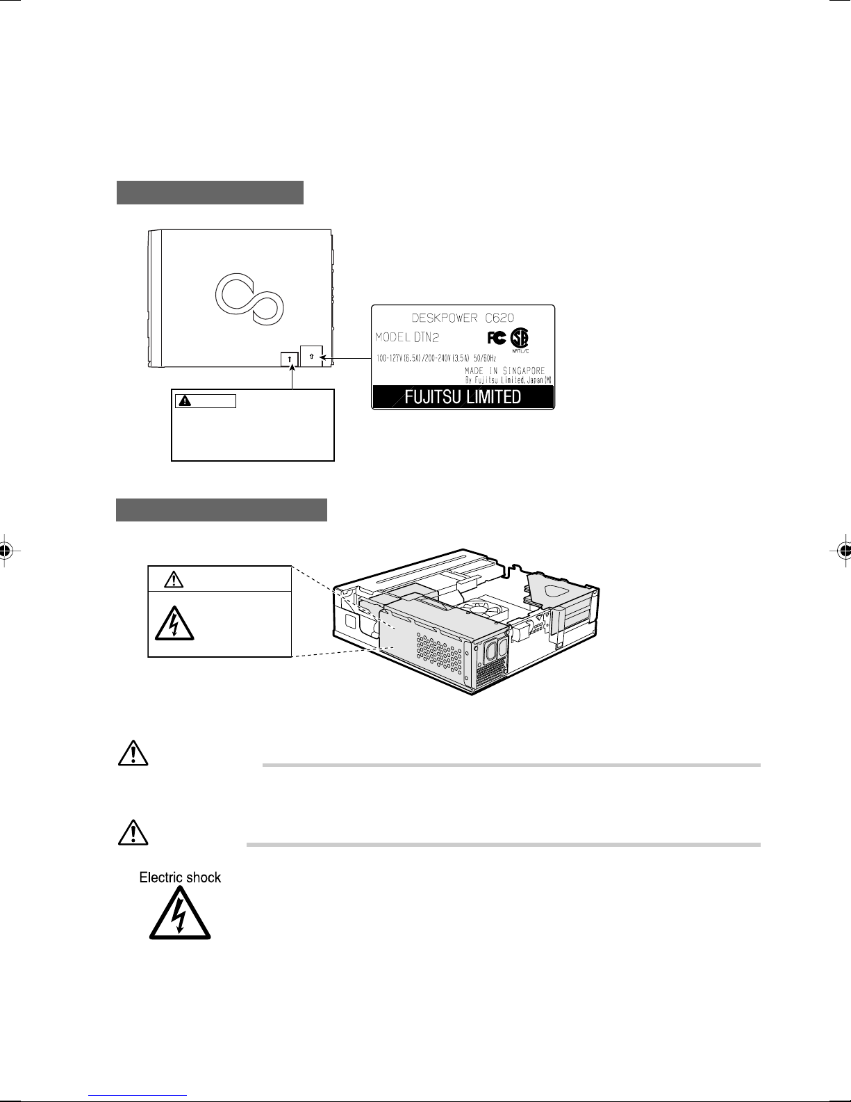
Warning and caution labels
Your PC bears the warning and caution labels as shown below.
The warning and caution labels must not be removed or damaged.
Side of PC main unit
WARNING
Electric shock
When removing exterior parts in
order to mount option parts or
others inside the cabinet, switch
off the power supply for PC unit
and peripheral devices linked
with it, and disconnect the power
cable from outlet before working
to avoid risk of electric shock.
Inside the PC main unit
WARNING
Electric shock
To prevent electric
shock and/or fire, do
not remove the cover
of this unit, which
includes a high
voltage section.
ATTENTION
115V of voltage switch in the power supply corresponds to 100-127V
230V of voltage switch in the power supply corresponds to 200-240V
WARNING
• Before mounting or dismounting an optional unit in/from your PC, switch off
the PC and all connected units and unplug all power cords from respective
outlets to prevent electric shock.
xi
Page 12

Organization of This Manual
Before Reading This Manual
This section contains cautions for safe operation, representations and symbols used in this manual.
Be sure to read this first!
Chapter 1 Preparing for Use
This chapter provides the names and functions of individual parts.
Chapter 2 Operation
This section describes the location of installation and installation of the computer.
Chapter 3 Security
This chapter introduces the security functions available on the PC unit. To prevent
an illegal use and information leakage to another person, take security measures
in routine use.
Chapter 4 Troubleshooting and Tips
This chapter provides the basic information on the PC and operation.
Chapter 5 System Expansion
This chapter provides basic information on how to handle the peripherals installed
(or can be installed) on the PC.
Chapter 6 Technical Data
Electrical Data
xii
Page 13

Contents
CHAPTER 1 Preparing for Use
1 Preparing for Use..............................................................................2
Unpacking and checking the delivery............................................................... 2
Steps for initial setup........................................................................................ 2
Setting up the PC ............................................................................................. 3
Connect the monitor, mouse and keyboard .....................................................6
Connecting the PC to the mains voltage.......................................................... 8
Initial switch-on: Software will be installed........................................................ 9
Connecting external devices .......................................................................... 10
CHAPTER 2 Operation
1 Operation.........................................................................................16
Switching On the PC ...................................................................................... 16
Switching Off the PC ...................................................................................... 16
Indicators on the PC....................................................................................... 17
2 CDs...................................................................................................18
Inserting or removing a CD ............................................................................ 19
CHAPTER 3 Security
1 Security............................................................................................22
2 Security during Network Connection ...........................................23
Computer virus ............................................................................................... 23
Encrypting the communication data ............................................................... 23
Firewall........................................................................................................... 23
3 Security Against Illegal Use...........................................................24
Passwords for Windows OS ........................................................................... 24
Administrator Authority and User Accounts ...................................................24
Access Authority and Encrypting ................................................................... 24
Password for the BIOS ................................................................................... 25
4 Burglary Prevention Of The PC .....................................................26
xiii
Page 14

CHAPTER 4 Troubleshooting and Tips
1 Troubleshooting and Tips ..............................................................28
Installing new software................................................................................... 28
Power-on indicator remains unlit after you have
switched on your device ................................................................................. 29
No mouse pointer displayed on the screen.................................................... 31
The floppy disk cannot be read or written ...................................................... 31
Time and/or date is not correct ...................................................................... 31
Error messages on the screen ....................................................................... 32
Restoring the hard disk contents.................................................................... 32
Tips ................................................................................................................ 32
CHAPTER 5 System Expansion
1 System Expansions........................................................................34
Information about boards ............................................................................... 34
Removing the cover ....................................................................................... 35
Installing the cover ......................................................................................... 36
Installing and removing a board ..................................................................... 37
Installing a board............................................................................................ 38
Low-Profile boards ......................................................................................... 42
Installing and removing the hard disk............................................................. 43
Installing the hard disk ................................................................................... 44
Installing memory modules ............................................................................ 46
Location of memory modules ......................................................................... 47
Applicable memory modules ..........................................................................47
Installing memory modules ............................................................................ 48
CHAPTER 6 Technical Data
1 Technical Data.................................................................................51
Electrical Data ................................................................................................ 52
xiv
Page 15

CHAPTER 1
Preparing for Use
Page 16
1 Preparing for Use
CAUTION
Please take note of the safety information in the "Important notes" chapter.
■ Unpacking and checking the delivery
It is recommended not to throw away the original packaging material! It may be required for reshipment
at some later date.
● Unpack all the individual parts.
● Check the delivery for damage incurred during transportation.
● Check whether the delivery agrees with the details in the delivery note.
Should you discover that the delivery does not correspond to the delivery note, notify your local sales
outlet immediately.
■ Steps for initial setup
Only a few steps are necessary to put your new PC into operation for the first time:
– Select location for PC and set up PC
– Connect the monitor, mouse and keyboard
– Check the voltage at the mains outlet and connect the PC to an electrical outlet
– enable PC
You will learn more about the individual steps in the following sections.
● External devices
If you have received other devices in addition to your PC (e.g. a printer or a modem), do
not connect these until after the initial installation. The following sections contain a
description of how to connect these external devices: "Connecting external devices to
the serial port" and "Connecting external devices to the parallel port".
● Drives and boards
If you have received drives or boards with your PC, please do not install them until after
first-time setup. How to install drives and boards is described in the "System expansions"
chapter.
2
Page 17
■ Setting up the PC
CAUTION
When installing your PC, give consideration to the recommendations and safety notes in the "Safety
and Ergonomics" booklet.
Set up the PC only in its correct orientation. The points to observe are illustrated on the following
pages.
Do not expose the PC to extreme environmental conditions (see "Technical data" chapter) and
protect it from dust, humidity and heat. Protect the PC from dust, humidity and heat.
When installing the PC, provide sufficient clearance around the PC, as indicated in the "Technical
data" chapter to ensure adequate ventilation. Do not cover the ventilation area of the monitor or
the PC.
Do not place several PCs one above the other.
The PC can be used either horizontally or vertically. We recommend that you place your equipment
on a surface with good anti-slip qualities. In view of the multitude of different finishes and varnishes
used on furniture, it is possible that the rubber / plastic feet or the base feet of the devices will mark the
surface they stand on.
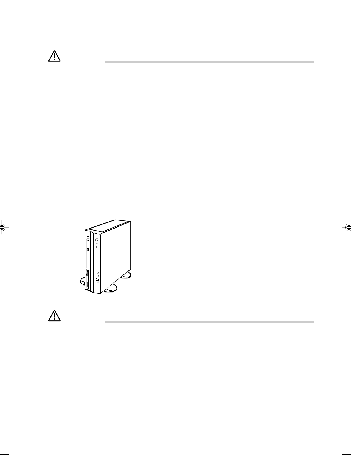
Vertical operating position
CAUTION
The vertical operating position is only permissible with base feet. The base feet secure the device
against tipping over.
3
Page 18
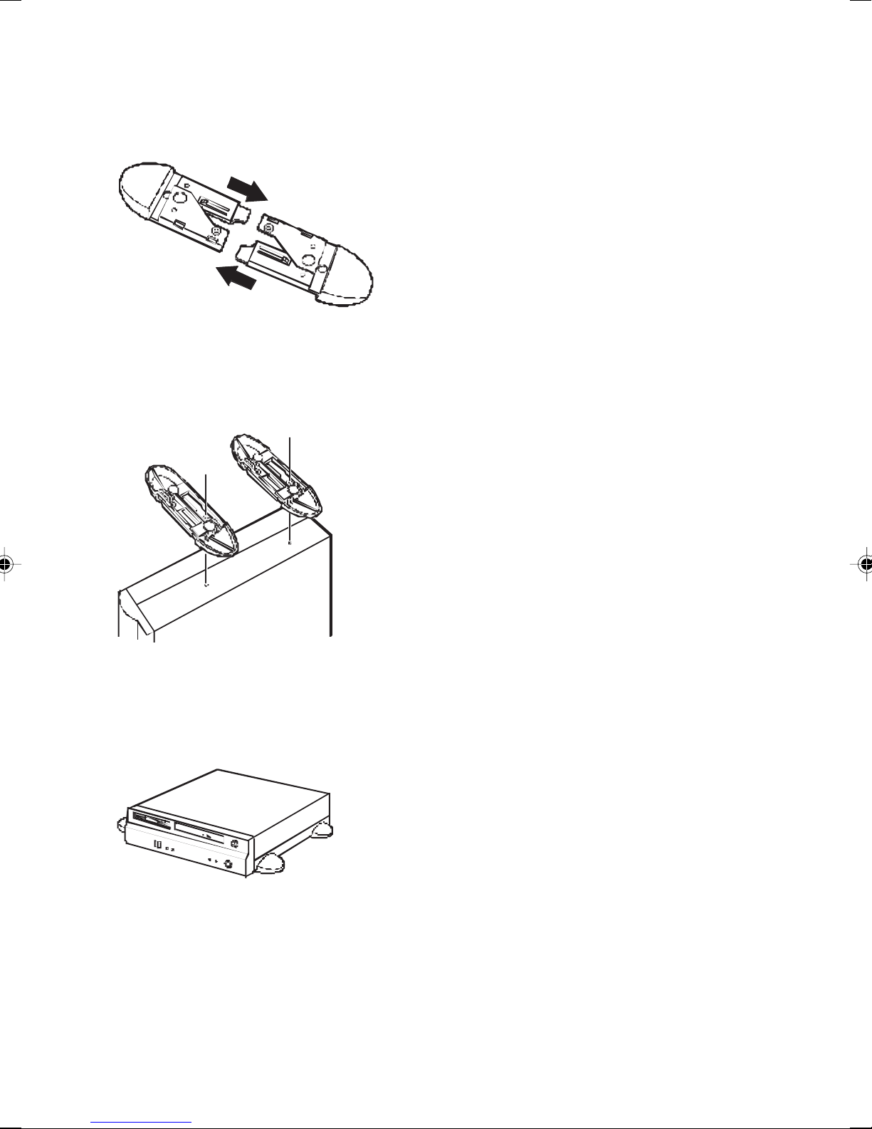
Proceed as follows to prepare the PC for the vertical operating position:
Disconnect the cables.
Assemble the base feet in the direction of the arrow.
Set up the casing in a vertical position so that the holes provided for the screws (on the side of the
device) are facing upwards.
Fix the base feet with the supplied screws (1). One screw is provided per each foot and opening.
1
1
Place the unit on the base feet and reconnect any cables disconnected previously.
Horizontal operating position
You may operate the device in a horizontal position with rubber / plastic feet or with base feet.
4
Page 19
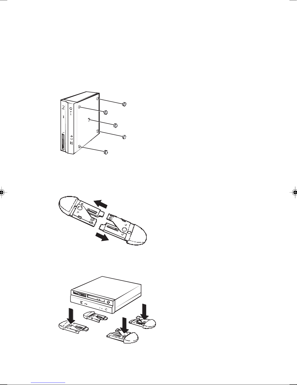
Horizontal operating position with rubber / plastic feet
Disconnect the cables.
Position the device vertically.
Pull off the foil from the rubber / plastic feet.
Stick the rubber / plastic feet on the base of the casing.
To ensure stable position of the device the rubber / plastic feet should be fixed in similiar positions
as shown in the figure.
Place the unit on the rubber / plastic feet and reconnect any cables disconnected previously.
Horizontal operating position with base feet
Disconnect the cables.
Remove any bothersome rubber / plastic feet.
Take apart the base feet in the direction of the arrow.
Place the device on the base feet. Make sure that the device is lying level, straight and not tilted
on the base feet.
If necessary, reconnect the cables.
5
Page 20
■ Connect the monitor, mouse and keyboard
The ports for the monitor, mouse, and keyboard are on the rear and front of the PC.
PS/2 keyboard port / purple PS/2 mouse port / green
Monitor port / blue USB port / black
Connecting the monitor
● Follow the instructions contained in the monitor manual to prepare the monitor for operation (e.g.
connecting cables).
● Plug the data cable into the monitor port of the PC.
1
● Depending on the connector supplied with your monitor, plug the monitor's power cable into either
the PC (1) or the mains supply (2).
CAUTION
The monitor power cable may only be connected to the PC monitor socket if the monitor current
consumption is smaller than 1,5 A with 230 V or 3 A with 115 V. The values for the monitor current
consumption can be found in the technical data on the monitor or in the operating manual for the
monitor.
6
Page 21

Connecting the mouse
Depending on the equipment level selected, your PC will be supplied with a PS/2 mouse or a USB
mouse.
Connecting a PS/2 mouse
Connect the PS/2 mouse to the PS/2 mouse port of the PC.
Connecting USB mouse
● Connect the USB mouse to the USB port of the PC.
If you do not attach a mouse at the PS/2 mouse port, you can disable the mouse controller in
the
BIOS Setup
in order to free the IRQ12 for a different application.
Connecting a keyboard
Depending on the equipment level selected, your PC will be supplied with a standard keyboard or a
USB keyboard.
Connecting standard keyboard
Use the supplied keyboard cable only.
● Plug the rectangular connector of the keyboard cable into the rectangular socket on the underside
or on the rear of the keyboard.
● Plug the round plug of the keyboard cable into the keyboard port of the PC.
Connecting USB keyboard
Use the supplied keyboard cable only.
● Plug the rectangular connector of the keyboard cable into the rectangular socket on the underside
or on the rear of the keyboard.
● Insert the flat rectangular USB plug of the keyboard cable into a USB port
of the PC.
7
Page 22

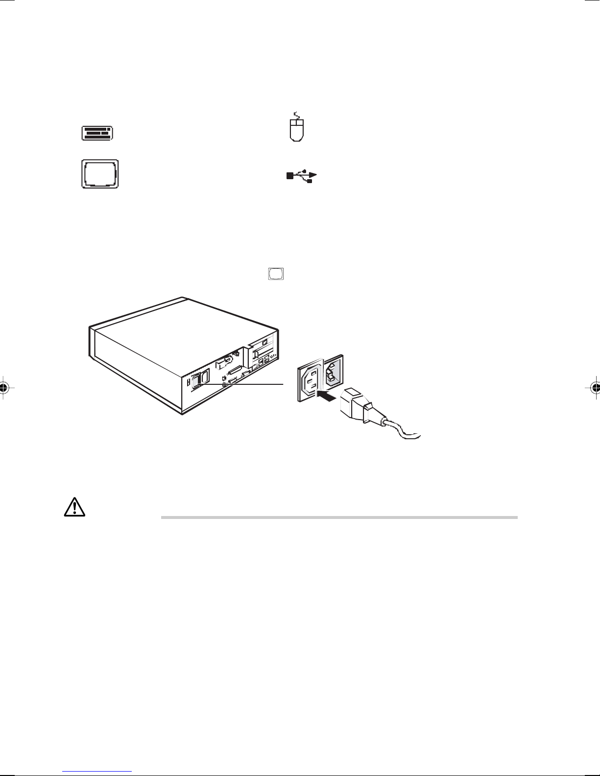
■ Connecting the PC to the mains voltage
100 V - 127 V 200 V - 240 V
3
2
0
1
1
5
Check the voltage setting.
CAUTION
The visible value must agree with the local mains voltage:
• 115 = 100 V to 127 V
• 230 = 200 V to 240 V
If an incorrect mains voltage is set, push the slide switch in the direction of the arrow all the way
into the other possible position with a pointed object.
Connect the power cable to the PC (1).
Plug the power plug into the grounded mains outlet (2).
8
1
Page 23

■ Initial switch-on: Software will be installed
If the PC is integrated into a network, the user and server details as well as the network protocol are
required during the software installation. Contact your network administrator if you have any questions
about these settings.
When you switch on your PC for the first time, the supplied software is installed and configured.
You should plan some time for this, as this process must not be interrupted.
CAUTION
Once the installation has been started the PC must not be switched off!
During installation the PC may only be rebooted when you are requested to do so!
Otherwise the installation will be not be performed correctly. If a fault occurs during the installation,
the contents of the hard disk must be completely restored.
You may require the Windows licence number during installation. This number is located on a
sticker on your PC.
Switching on monitor and PC
Switch the monitor on (see the operating manual for the monitor).
Switch the PC on.
1
2
1 = ON/OFF switch 2 = Power-on indicator
Press the ON/OFF switch (1) on the front of the casing in the direction of the arrow.
The power-on indicator (2) lights green and the PC is started.
Installing the software
During installation, follow the instructions on screen.
Consult the operating system manual if there is anything unclear about the requested input data.
You will find further information about the system, drivers, utilities, updates, manuals etc. on
the "Drivers & Utilities" CD supplied.
9
Page 24

■ Connecting external devices
CAUTION
Read the documentation on the external device before connecting it.
Do not connect or disconnect cables during a thunderstorm.
Always take hold of the actual plug. Never unplug a cable by pulling the cable itself.
Connect and disconnect the cables in the order described below.
With the exception of USB devices, always remove all power plugs before connecting external
devices!
Connecting cables
Turn off all power and equipment switches.
Remove all power plugs from the mains outlets.
Plug all cables into the PC and peripherals. You must observe the information provided in the
"Important notes" chapter.
Plug all data communication cables into the utility sockets.
Plug all power cables into the grounded mains outlets.
Disconnecting cables
Turn off all power and equipment switches.
Remove all power plugs from the mains outlets.
Unplug all data communication cables from the utility sockets.
Unplug all cables from the PC and peripherals.
USB devices are hot-pluggable. This allows cables from USB devices to be connected and
disconnected with the system switched on.
Additional information can be found in the "Connecting external devices to the USB ports"
section and in the documentation for the USB devices.
10
Page 25

Ports
The ports for external devices are on the rear and on the front of the PC. The ports available on your
PC depend on the configuration level you have selected. The standard ports are marked with the
symbols shown below (or similar). Exact details of the position of the ports are supplied in the technical
manuals for the boards.
Keyboard port / purple
1
Serial interface 1 / turquoise
Monitor port / blue
Headphones port / orange / light green
Audio output (Line out)/ light green
USB - Universal Serial Bus / black
LAN
LAN connector
PS/2 mouse port / green
2
Serial interface 2 / turquoise
Parallel interface / Printer / burgundy
Microphone jack (mono) / pink
Audio input (Line in) / light blue
Loudspeaker / orange
Some of the devices that you connect require special drivers (see the operating system and
device documentation).
11
Page 26

Connecting external devices to the serial port
External devices can be connected to the serial port (e.g. a modem).
Connect the data cable to the external device.
Connect the data cable to the serial port .
For an exact description of how to connect external devices to the serial port , please refer to the
device documentation.
Settings of the serial port
If you need to change the settings of the serial port (e.g. address, interrupt), you can do so
in the
BIOS Setup.
Device drivers
The devices connected to the serial port require drivers. Your operating system already
includes many drivers. Nevertheless, if the driver you need is not on the hard disk, please
install it from the data carrier supplied with the device or with the application programme.
12
Page 27

Connecting external devices to the parallel port
External devices can be connected to the parallel port (e.g. a printer).
Connect the data cable to the external device.
Connect the data cable to the parallel port .
For an exact description of how to connect external devices to the parallel port, please see the device
documentation.
Settings of the parallel port
If you need to change the settings of the parallel port (e.g. address, interrupt), you can do
so in the
Device drivers
The devices connected to the parallel port require drivers. Your operating system already
includes many drivers. Nevertheless, if the driver you need is not on the hard disk, please
install it from the data carrier supplied with the device or with the application programme.
BIOS Setup.
13
Page 28

Connecting external devices to the USB ports
You can connect a wide range of external devices to the USB port (e.g. printer, scanner, modem or
keyboard).
USB devices are hot-pluggable. This allows cables from USB devices to be connectedand
disconnected with the system switched on.
Connect the data cable to the external device.
Connect the data cable to the USB port .
Device drivers
The devices you connect to the USB ports usually require no driver of their own, as the
required software is already included in the operating system. However, if the USB device
requires its own software, please install it from the data carrier provided with the USB
device.
14
Page 29

CHAPTER 2
Operation
Page 30

1 Operation
■ Switching On the PC
Switch the monitor on (see the operating manual for the monitor).
Press the ON/OFF switch on the front of the casing.
The power-on indicator lights green and the PC is started.
■ Switching Off the PC
Shut down the operating system properly. For Windows: select
If the operating system does not automatically switch the PC off, turn the PC to ready-tooperate
when requested to do so by pressing the ON/OFF switch.
If the PC is ready-to-operate, the PC consumes very little power.
Shut Down
from the
Start
menu.
CAUTION
The power button does not disconnect the PC from the mains voltage. To completely
disconnect the mains voltage, remove the power plug from the socket.
If necessary, switch the monitor off (see the operating manual for the monitor).
Placing a PC (with soft power off function) in a ready-to-operate state by means of software
With the soft power off function the PC automatically switches off (standby) or switches into the energy
saving mode after the operating system is shut down. Requirements: Your system must support
switching off with software and this functionality must be enabled in BIOS Setup. The soft power off
software may also need to be installed on Windows NT systems.
16
Page 31

■ Indicators on the PC
The indicators are on the front of the casing. Which indicators are available on your PC depends
on the configuration level you have selected.
4
5
1 = CD-ROM indicator 4 = Indicator SmartCard reader (if installed)
2 = Hard disk indicator 5 = Floppy disk indicator
3 = Power-on indicator
1 SmartCard reader indicator
The indicator lights up if a SmartCard is inserted.
The indicator flashes if no SmartCard is inserted.
2 Hard disk indicator
The indicator lights up when the hard disk drive of the PC is accessed.
3 Power-on indicator
– The indicator lights green:
The PC is on.
– The indicator lights up orange:
The PC is ready-to-operate or in energy-saving mode. After being switched on with thepower
button, the PC switches on or returns to the state it was in before the energy-saving mode.
213
CAUTION
In the energy-saving mode the PC may not be disconnected from the mains supply, as this may
otherwise result in data loss.
– The indicator does not light up:
The PC is disconnected from the power supply or is ready for operation. If the PC is ready-tooperate, the PC can be enabled with the ON/OFF switch.
4 CD-ROM indicator
The indicator lights up when the CD-ROM drive is accessed. You may only remove the CD when
the indicator is unlit.
5 Floppy disk indicator
The indicator lights up when the floppy disk drive of the PC is accessed. You may only remove
the floppy disk when the indicator is unlit.
17
Page 32

2 CDs
This section describes how to handle, insert, and remove a CD.
Notes on Handling
Follow the following guidelines to prevent faults when handling a CD.
Guidelines for CD Media
● Apply no label to any side of the disk. Do not use a ballpoint pen or pencil.
● Do not touch or damage the data side.
● Do not bend the disk or put a heavy object on it.
● If the disk has dirt or water droplets, use a damp cloth to wipe them off and clean the disk with
a dry cloth. Always wipe the disk along the radius.
● Keep the disks dry.
● Do not place the disks in an extreme temperature environment.
● Do not place the disks in a humid and dusty environment.
Notes on Using the Drive
● Do not use the CD, if it is not safeguarded according to “Handling guidelines for CD media”
above, or it has bends, cracks, or fissures. Otherwise, a fault may occur. The warranty is not
applied to any failure caused by the use of such CDs.
● This PC accepts only round CDs. Do not use odd-shaped CDs. Otherwise, a fault may occur.
The warranty is not applied to any failure caused by the use of CD in a variant shape.
● Use of a commercially available CD-ROM drive cleaning disk may put dusts on the lens. Do
not use a CD-ROM drive cleaning disk.
Point
• A CD-ROM is the same as a music CD (compact disc) except it has computer information
(characters) instead of sound. ROM stands for Read Only Memory. This PC can read data
from CD-ROMs but cannot write data, except when CD-R/RW is selected .
• This PC accepts any CD that has one of the following marks. Do not use the CD if it does not
carry any of them. Or, it may cause a failure. An additional application may be necessary to
use particular types of CDs.
*1 You can write on the CD if you have a CD-R/RW drive.
*2 If you write data at 8X speed or higher, you need to have a high speed-ready drive.
18
Page 33

■ Inserting or removing a CD
● Inserting a CD
1 Press the CD eject button.
Press the middle of the CD eject button, and the CD tray pops out.
CD access lamp
CD eject button
2 Pull the tray out with a hand.
As shown in the figure, hold the center of the tray.
Tray
3 Mount the CD by facing its label to the left, and push the CD until it snaps onto the hub
at the center of the tray.
When pressing the CD, hold the tray not to tip over the PC.
Label side
Hub
Point
Be sure to press the CD until it snaps onto the hub at the center of the tray. Otherwise, a fault may
occur.
19
Page 34

4 Manually push the tray until it clicks.
The tray goes into the computer, and sets the CD.
Point
• The CD access lamp lights when the CD is set. Wait until the CD access lamp turns off, and
then do the following.
• The tray is not set correctly, if you press the CD eject button while pushing in the tray.
● Removing the CD
Before ejecting the CD, make sure that the CD access lamp is off. If OK, press the CD eject button.
20
Page 35

CHAPTER 3
Security
Page 36

1 Security
Connect the display, keyboard, and power cord to the PC.
WARNING
● The security functions do not guarantee the complete check of personal identification. Fujitsu
is not responsible to any damage that is caused by the use of security functions or no use of
them.
The PC owner is responsible to its security.
● The PC user needs to regularly maintain the PC security environment in order to minimise
unauthorised access.
When the PC is used, the danger of system destruction by computer virus, the leakage of
information, illegal use, burglary and others increases. To protect important information from these
danger, the PC has various security functions.
The following briefly explains the danger that may exist and the preparation useful for problem
solution.
● Computer virus
Computer Virus are made using PCs to corrupt data or destroy data on other users PCs. The
virus infects other PCs thru the Internet ,e-mails and downloads.
● Information leakage
Computer viruses can enter PCs via the network to steal or destory important data. Information
may be retrieved illegally from disposed PCs by using special softwares.
Point
Take extra care when disposing floppy disks, CD-R/RW disks and MO disks which contains
sensitive data.We recommend to scratch the disk media or completely erase the data before
disposing.
● Illegal use
To prevent unauthorised use of your deskpower,we recommend the use of a password during
setup and general usage.Unauthorized access to your PC can be minimised if you use a password
that is difficult to guess.
● Burglary
The PC may be stolen and the data in the PC may be used illegally against the owner.
● Preparing for the trouble
No perfect security of the PC exists. You can minimize the damage by making a backup copy of
data and updating the software to the latest version.
For more information, refer to the “Preparing for the trouble” section of “Troubleshooting.”
22
Page 37

2 Security during Network
Connection
Information is often transferred via the network such as Internet and e-mails. Therefore, the
possibility of computer virus infection and information leakage due to hacking is always there.
The following, introduces the security functions to protect the PC connected to the network.
■ Computer virus
Computer virus infects the PC through the Internet and e-mails, leading to data corruption, loss
of data or system malfunction. If you use a PC which is infected with a computer virus you may
spread the virus on other PCs without knowing it.
■ Encrypting the communication data
When data are being exchanged via the network, it may be leaked from the network. The encrypted
data transmission rate is increased to avoid such problems.
Windows XP and 2000 OSs have standard data encryption functionalities. The following introduces
an example of Internet Protocol Security (IPSec) encryption functionality.
The IPSec allows users to encrypt data during TCP/IP protocol communication independent from
the applications used.
If you are using a secured LAN card, you can reduce the CPU load as the encrypted data
communication is processed by the card itself. Therefore, you can use the encrypted
communication without affecting another job.
See the Windows Help for details.
■ Firewall
If the PC is connected to an external network, the PC may be accessed illegally from the external
network and its data may be altered. To prevent such problem, you can create a firewall between
the internal and external networks and control any access from the outside.
The Windows XP has the standard Internet Connection Firewall (ICF).
See the Windows Help for the ICF.
23
Page 38

3 Security Against Illegal Use
It is necessary to protect your PC from any unauthorized person from destroying or removing
data from the PC.
The following explains the password and its functions you can set on the PC. The security of the
PC is increased by a combination of multiple passwords and security functions.
WARNING
● You must cancel the password protection when returning the PC for services. The repair
service is charged even within the warrantee period if the PC is password protected.
● Keep the password in a safe place if you have written it down. Use not only digits but also
alphabets and symbols for the password. Change your password periodically so as to ensure
that your password is not made known to other people.
When the PC is used, the danger of system corruption by computer virus,information leakage,
illegal use, burglary and others increases. To protect important information from these danger,
the PC has various security functions.
The following briefly explains the danger that may exist and the preparation useful for problem
solution.
■ Passwords for Windows OS
You can set up a password for the time when the OS starts up, when the PC resumes from the
standby mode, and when the PC restores from the screen saver. If a single PC is used by multiple
users, the password can be changed for each user.
For the password setup details, see the Windows Help.
■ Administrator Authority and User Accounts
The Windows XP and 2000 OSs allow you to create a user account having the administrator rights.
The administrator can set up and control the account of other users. As the administrator controls
the PC users, the PC security is improved.
See the Windows Help for details.
■ Access Authority and Encrypting
If you use the NTFS file system of the Windows XP or Windows 2000 OS, you can:
● Set up an access authority to folders and files.
As the access authority can be set for each user or each group, you can protect files from
being accessed by unauthorized users.
● Encrypt folders and files.
If you have lost the hard disk unit by the accident, the encrypted file contents are hard to be
read byothers.
Important data can be protected from being read by unauthorized users if the access rights of the
data have been set or the data have been encrypted.
See the Windows Help for details.
24
Page 39

■ Password for the BIOS
A password can be set for the time when the PC starts up or resumes. There are two types of
BIOS passwords: the administrator password and the user password. If a user enters the user
password, he or she cannot change the PC settings and others. Some PC operations are limited.
A password can also be set for the hard disk of the PC. If you have set a password for the hard
disk unit, only the person who knows the password can read information from the hard disk.
25
Page 40

4 Burglary Prevention Of The PC
The PC may be burglarized. Although you can protect the PC by keeping or installing it in a place
behind the locked door, the PC itself has the burglary prevention function.
The PC can be protected against the theft if the burglarproof cable is tied up at the burglarproof
lock.
The burglarproof lock supports the Microsaver security system of Kensington.
26
Page 41

CHAPTER 4
Troubleshooting
and Tips
Page 42

1 Troubleshooting and Tips
CAUTION
Take note of the safety notes in the "Safety and Ergonomics" manual and in the "Preparing for
use" chapter, when you connect or disconnect cables.
If a fault occurs, try to correct it as described in the following places:
in this chapter
in the documentation of the connected devices
in the help systems of the software used.
in the documentation of your operating system
If you fail to correct the problem, proceed as follows:
Switch the PC off.
Make a note of the steps and the circumstances that led to the fault.
Make a note of any error messages displayed.
Note the ID number of your device.
This number can be found on the type rating plate on the back of the casing.
Contact your sales outlet or our customer service centre.
■ Installing new software
When installing programmes or drivers, important files may be overwritten and modified. To be able
to access the original data in the event of any problems following installation, you should backup your
hard disk prior to installation.
28
Page 43

■ Power-on indicator remains unlit after you have
switched on your device
This may be due to the following:
The mains voltage supply is faulty
Check that the power cable is properly plugged into the PC and grounded mains outlet.
Switch the PC on.
Internal power supply overloaded
Remove the PC’s power plug from the grounded mains outlet.
Wait for a moment.
Plug the power plug into the grounded mains outlet again.
Switch the PC on.
The screen stays blank
If your screen remains blank this may be due to the following:
Monitor is switched off
Switch your monitor on.
Power saving has been activated (screen is blank)
Press any key on the keyboard.
or
Deactivate the screen saver. If neccessary, enter the appropriate password.
Brightness control is set too dark
Adjust the brightness control. For detailed information, please refer to the operating manual
supplied with your monitor.
29
Page 44

Power cable not connected
Switch off the monitor and the PC.
Check that the monitor power cable is properly connected to the monitor and, depending on the
connector, to the PC or to a grounded mains outlet.
Check that the PC power cable is properly plugged into the PC and grounded mains outlet.
Switch on the monitor and the PC.
Monitor cable not connected
Switch off the monitor and the PC.
Check that the monitor cable is properly connected to the PC and monitor.
Switch on the monitor and the PC.
Wrong monitor has been set under Windows 2000
Restart the PC.
If the message Starting Windows appears, press function key [F8].
The Windows 2000 Advanced Options Menu appears.
Select Safe Mode or Safe Mode with Network.
Set the correct values for the attached monitor as described in the operating manual of the monitor
by selecting Start - Settings - Control Panel - Display - Settings.
Wrong monitor has been set under Window XP
Restart the PC.
Press [F8] while the system is booting.
Either the Windows Advanced Start Options menu or the menu for selecting the operating system
appears.
If the menu for selecting the operating system appears, press [F8].
Select Safe Mode or Safe Mode with Network.
Set the correct values for the attached monitor as described in the operating manual of the monitor
by selecting Start → Settings → Control Panel → Display → and then the Appearance, Themes,
Settings tabls.
The wrong RAM modules have been inserted
See the technical manual for the mainboard for information on which memory modules can be used.
30
Page 45

■ No mouse pointer displayed on the screen
Shut down the operating system properly.
Switch the PC off.
Check that the mouse cable is properly connected to the system unit.
If you use an adapter or extension lead with the mouse cable, check the connections.
Make sure that only one mouse is connected.
Switch the PC on.
The mouse controller must be enabled if you use a PS/2 mouse on the PS/2 mouse port .
Check in the BIOS Setup that the mouse controller is Enabled.
Check that the mouse driver is properly installed and is present when the application programme
is started. Detailed information can be found in the user guide for the mouse and application
programme.
■ The floppy disk cannot be read or written
Check whether the write protection of the floppy disk or the floppy disk drive is activated.
Check the relevant entries for Diskette A: or B: in the Main menu of the BIOS Setup.
Check that the floppy disk drive controller is enabled (refer to the "BIOS Setup" manual and if
necessary to the technical manual for the mainboard).
Check that the cables of the floppy disk drive are properly connected (refer to “Installing and
removing the floppy disk drive” chapter).
■ Time and/or date is not correct
You can set the time and date in the BIOS Setup or in the operating system.
Set the time and date.
If the time and date are repeatedly wrong when you switch on your PC, the on-board battery
is flat. Change the lithium battery as described in the "Extensions to the mainboard" –
"Replacing lithium battery" chapter.
31
Page 46

■ Error messages on the screen
Error messages and their explanation are contained in the documentation for the program used.
■ Restoring the hard disk contents
Should you need to restore your hard disk, the instructions are provided on the case of the "Recovery
CD" (delivered with your system).
■ Tips
The PC cannot be switched off with the ON/OFF switch.
Cause: The PC was not switched on with the ON/OFF switch.
Press the ON/OFF switch again.
Cause: System crash
Press and hold the ON/OFF switch for at least four seconds until the PC switches off.
Out of system resources
If you have too many applications running at once, you may experience problems due to a lack of
system resources. In this case you should:
close unnecessary applications
or
run the applications in a different order.
32
Page 47

CHAPTER 5
System Expansion
Page 48

1 System Expansions
It may be necessary to update the BIOS when carrying out a system expansion or hardware
upgrade.The device must be switched off when installing/removing the system expansion.
This chapter describes all the activities required to modify your PC hardware (e.g. installing boards
or drives).
Read the supplied documentation before installing new drives and/or boards.
Refer to the technical manual for the mainboard before making any extensions to the mainboard.
Information about boards
Take care with the locking mechanisms (catches and centring pins) when you are replacing board or
components on on board.
To prevent damage to the board or the components and conductors on it, please take care when you
insert or remove boards. Make sure expansion boards are inserted straightly.
Never use sharp objects (screwdrivers) for leverage.
Boards with electrostatic sensitive devices (ESD) are identifiable by the label
shown.
When you handle boards fitted with ESDs, you must, under all circumstances,
observe the following points:
You must always discharge static build up (e.g. by touching a grounded
object) before working.
The equipment and tools you use must be free of static charges.
Remove the power plug from the mains supply before inserting or
removing boards containing ESDs.
Always hold boards with ESDs by their edges.
Never touch pins or conductors on boards fitted with ESDs.
34
Page 49

■ Removing the cover
Switch the PC off. The PC must not be in the energy-saving mode!
CAUTION
Please take note of the safety information in the "Important notes" chapter.
Pull the power plug out of the mains outlet!
Remove all cables from the casing.
Place the casing in a convenient working position.
If necessary, unlock the casing
1
Unlock the casing by pushing the locking slide (1) past a slight resistance in the direction of the
arrow until it engages. The locking slide is situated on the rear of the casing.
Push the top cover toward the front by a distance of (a) approx. 10 mm in the direction of the arrow
(1) and lift it off upward in the direction of the arrow (2).
1
a
a
2
35
Page 50

■ Installing the cover
Position the top cover from above in the direction of the arrow (1) on the casing base so that the
distance (a) from the rear casing edge is approximately 10 mm.
Push the top cover in the direction of the arrow (2) until it engages.
2
a
a
1
1
Lock the casing by pushing back the locking slide (1) in the direction of the arrow past a slight
resistance until it engages. The locking slide is situated on the rear of the casing.
Lock the casing again if necessary.
Return the PC of its original position.
Reconnect the cables.
36
Page 51

■ Installing and removing a board
CAUTION
Please take note of the section “Information about boards”.
Removing board bracket
Open the casing (see "Opening the casing" chapter).
Pull the board bracket out of the casing in the direction of the arrow.
Installing board bracket
Insert the board bracket in the casing in the direction of the arrow. The angle bracket of the board
bracket (a) have to fit into the guide rail and the guide lugs of the board bracket have to be positioned
above the depressions in the casing.
Close the casing (see “Closing the casing” chapter).
a
b
b
37
Page 52

■ Installing a board
Make the required settings for the board.
CAUTION
Do not dispose of the slot cover. For cooling, protection against fire and in order to comply
with EMC regulations, you must refit the slot cover if you remove the board.
Fold up the retaining bracket of the board bracket in the direction of the arrow.
Pull the slot cover out of the slot in the direction of the arrow (1).
1
38
Page 53

Push the board up to its slot (1) in the direction of the arrow as far as the stop.
Press the board into the slot so that it engages.
1
Fold close the retaining bracket so that it engages.
If necessary, connect the cables.
Reinstall the board bracket in reverse order as described above.
Close the casing (see "Closing the casing" chapter).
If you have installed or removed a PCI board, please check the relevant PCI slot settings in
the BIOS Setup. If necessary, change the settings. Further information is provided in the PCI
board documentation.
The upper slot is suitable for low-profile cards with an adapter.
39
Page 54

Removing a board
Disconnect the cables connected to the board.
Fold up the retaining bracket of the board bracket in the direction of the arrow.
Pull the board out of the slot of the board bracket in the direction of the arrow (1).
1
40
Page 55

Push the slot cover into the slot in the direction of the arrow (1). Ensure that the point of the cover
engages on the outside of the board bracket.
1
Fold close the retaining bracket so that it engages.
CAUTION
For cooling, protection against fire, and in order to comply with EMC (electromagnetic
compatibility) regulations, you must refit the slot cover.
If you have installed or removed a PCI board, please check the relevant PCI slot settings in
the BIOS Setup. If necessary, change the settings. Further information is provided in the PCI
board documentation.
41
Page 56

■ Low-Profile boards
For units with a particularly low overall height, there are so-called low-profile boards with a slot cover
with a lower overall height to match the low-profile units. To also install these low-profile boards in
normal board slots, you must mount a corresponding slot adapter beforehand.
Mounting slot adapter
Fit the slot adapter in the direction of the arrow (1) on the slot cover of the low-profile board and
screw it on (2).
Now you can install the low-profile board in a suitable slot like a normal board (see the "Installing
a board" chapter).
1
2
Removing slot adapter
Unscrew the screw (1) and remove the slot adapter in the direction of the arrow (2).
2
1
It may be necessary to modify the entry for the drive in the BIOS Setup.
42
Page 57

■ Installing and removing the hard disk
Open the casing (see "Opening the casing" chapter).
Removing the hard disk
Remove the data and the power supply connector from the the hard disk drive.
Handle the latch, fold open it in the direction of the arrow (1) and release it out of the anchor (2).
1
2
Handle both hooks (1) of the hard disk and pull the hard disk out of the drive cage in the direction
of the arrow.
1
1
Remove the hard disk from the bracket in the direction of the arrow.
If you do not intend to install a new hard disk, slide the bracket back into the slot. Then close off
the slot with the lock.
43
Page 58

■ Installing the hard disk
Open the casing (see “Opening the casing” chapter).
Make the required settings (e.g. master setting) on the drive.
Remove the data and the power supply connector from the the hard disk drive (1), if necessary.
Handle the latch, fold open it in the direction of the arrow (1) and release it out of the anchor (2).
1
2
Handle both hooks (1) of the carrier and pull it out of the drive cage in the direction of the arrow.
1
1
Place the new hard disk on the bracket in the direction of the arrow, so that the guide pins of the
carrier slot into the holes of the hard disk.
44
Page 59

Handle both hooks (1) of the hard disk and slide the new hard disk into the slot (2) in the direction
of the arrow.
1
1
Hook the the latch (1) and close it in the direction of the arrow (2).
Attach the connectors of the data and power cables at the hard disk drive.
2
1
Connect the blue plug of the data cable to the connection on the mainboard. Connect the
plug on the other end to the hard disk drive.
You may have to check the entry for the drive in the Setup menu.
45
Page 60

■ Installing memory modules
Increasing the memory capacity increases the amount of data that the system can read at one
access, thereby improving the processing capability of the PC.
Point
If you want to install a memory module to the PC you have just purchased, set up Windows, turn
off the PC, and then install the memory module.
CAUTION
● Before installing or removing a memory module, turn off the PC and all devices
connected to it, and unplug them.
Otherwise, an electric shock may occur.
● Use a Fujitsu memory module.
Otherwise, an electric shock, a fire or a fault may occur.
WARNING
● When installing or removing a memory module, do not remove screws other
than those specified.
Otherwise, a personal injury or a fault may occur.
● When accessing the PC board, touch the specified areas only.
Otherwise, a personal injury or a fault may occur.
46
Page 61

■ Location of memory modules
■ Applicable memory modules
Use Fujitsu 184-pin SDRAM DIMM memory modules only.
Up to 2G bytes of memory (two 1GB-byte memories) can be expanded.
In the standard configuration, slot DIMM1 has a memory module. Insert an additional memory
module into slot DIMM2.
The memory module in slot DIMM1 must be changed depending on the total memory capacity
you want.
● Memory Module Combinations
DIMM1 DIMM2 Total memory capacity
DDR 300
256 MB – 256 MB
256 MB 128 MB 384 MB
256 MB 256 MB 512 MB
256 MB 512 MB 786 MB
512 MB – 512 MB
512 MB 256 MB 768 MB
512 MB 512 MB 2 GB
1 GB – 2 GB
1 GB 1 GB 2 GB
DDR 400
128 MB 128 MB 256 MB
256 MB 256 MB 512 MB
512 MB 512 MB 2 GB
1 GB 1 GB 2 GB
47
Page 62

■ Installing memory modules
1 Unplug the PC.
2 Remove the upper cover.
48
Page 63

3 Pull the hooks on both sides of the slot outward.
4 Insert a memory module into the slot.
Insert the memory module into the slot while aligning the notch on the memory module with
that on the slot.
When the memory module is inserted correctly, the hooks on both side rise.Make sure that
the hooks hold the memory module securely.
Point
Take extremely care NOT to insert the memory module in the reverse direction. Or a fault may
occur.
49
Page 64

Point
To remove the memory module, pull the hooks on both sides of the slot outward.
Do not pull the hooks too quickly. Otherwise, the memory module may jump out of the slot and
become faulty.
5 Reinstall upper cover.
50
Page 65

CHAPTER 6
Technical Data
Page 66

■ Electrical Data
Rated voltage range: (selectable)
DESKPOWER C620
100 V -127 V / 200 V - 240 V
Frequency:
Max. rated current
• Casing with monitor socket
• Monitor socket (output)
Dimensions
Width/depth/height:
Weight
with the basic configuration
Environmental conditions
Environment class 3K2
Environment class 2K2
Temperature:
• Operating (3K2)
• Transport (2K2)
Condensation in operating must be
avoided.
50 Hz -60 Hz
100 V -127 V / 6,0 A
200 V -240 V / 3.0 A
100 V -127 V / 3.0 A
200 V -240 V / 1,5 A
202 mm/376 mm/372 mm
11 kg in basic configuration
DIN IEC 721 part 3-3
DIN IEC 721 part 3-2
15 °C .... 35 °C
-25 °C .... 60 °C
Clearance required to ensure adequate
ventilation:
• left
• front
• rear
min. 200 mm
min. 200 mm
min. 200 mm
52
 Loading...