

Page 1

Operating Manual
FUJITSU Desktop
ESPRIMO D5xx / D7xx / D9xx
System
Page 2

Thank you for buying an inno
vative product from Fujitsu.
Latest information abo
on our website: "
You c a n find driver upda
Should you have any te
• our Hotline/Service
"
http://support.t
• Your sales partner
• Your sales office
We hope you enjoy using your new Fujitsu system!
ut our products, useful tips, updates etc. is available
//www.fujitsu.com/fts/"
http:
tes at: "
http://support.ts.fujitsu.com/download"
chnical questions, please contact:
Desk (see Service Desk list or from the Internet at:
s.fujitsu.com/contact/servicedesk")
Page 3

Page 4

Published by / Contact address in the EU
chnology Solutions GmbH
Fujitsu Te
Mies-van-der-Rohe-Straße 8
80807 Munich, Germany
www.fujitsu.com/fts/"
http://
"
Copyright
u Technology Solutions GmbH 2015. All rights reserved.
©Fujits
Publication Date
09/2015
Order No.: A26361-K1186-Z320-1-7619, edition 1
Page 5

FUJITSU Desktop
ESPRIMO D5xx / D7xx / D9xx
Operating Manual
Your ESPRIMO 7
Ports and operating elements 9
Important notes 11
Getting started 15
Operation 24
Problem solutions and tips 30
System expansions 34
Technical specification 76
Index 77
Page 6

Remarks
Information on the product description meets the d esign specifications of Fujitsu and
is provided for comparison purposes. Several factors may cause the actua l results to
differ. Technical data is subject to change without prior notification. Fujitsu rejects any
responsibility with regard to technical or editorial mistake s or omissions.
Trademarks
Fujitsu, the Fujitsu logo and ESPRIMO are registered trademarks of Fujitsu Limited or its
subsidiaries in the United States of America and other countries.
Kensington, MicroSaver and K-Slot are registered trademarks of ACCO Brands.
Microsoft and Windows are trademarks or registered trademarks of the Microsoft
Corporation in the United States and/or other countries.
All other trademarks specified here are the property of their respective owners.
Copyright
No part of this publication may be copied, reproduced or translated without
the prior written consent of Fujitsu.
No part of this publication may be saved or transferred by any electronic means
without the written approval of Fujitsu.
Page 7

Contents
Contents
YourESPRIMO ......................................................................... 7
Validityofthe ReferenceManual ......................................................... 7
Notational conventions .................................................................. 8
Ports and operating elemen
Front ................................................................................... 9
Rear ................................................................................... 10
Important notes ........................................................................ 11
Safety information ....................................................................... 11
Transporting the device .................................................................. 11
Cleaningthe device ..................................................................... 12
Energy saving, disposal and recycling .................................................... 12
CE marking ............................................................................ 13
FCC Compliance Statement ............................................................. 14
FCC ClassB Compliance Statement .................................................. 14
FCC RadiationExposureStatement .................................................. 14
Getting started ......................................................................... 15
Unpacking and che
Steps for initia
Setting up the de
Vertical opera
Connecting th
Connecting ex
Ports on the de
Connecting a
Connecting t
Connecting t
Connecting
Connecting
Switching
Operation .............................................................................. 24
Switch the device on .................................................................... 24
Switching off thedevice ................................................................. 24
Indicators onthe device ................................................................. 25
Keyboard ............................................................................... 26
Settingsin BIOS Setup .................................................................. 27
Property and data protection . . ........................................................... 28
Pro
Hel
Tr
on for the first time:installing the software .......................................
Switch on t
ng thesoftware ...............................................................
Installi
Procedure in an emerg ency . . . ....................................................... 24
Important keys and keyboard shortcuts . . . . ............................................ 26
Mechanically protecting and locking the casing ........................................ 28
BIOSsetupsecurity functions ........................................................ 29
Access authorisationvia SmartCard .................................................. 29
Operating the SmartCard reader (optional) ............................................ 29
blemsolutionsand tips ............................................................
pif problems occur ...................................................................
oubleshooting . . . ......................................................................
cking thedelivery .....................................................
lsetup ....................................................................
vice ....................................................................
tingpositionwith feet (optional) ..........................................
edevice to the mains supply ................................................
ternal devices .............................................................
vice ..................................................................
monitor ................................................................
he mouse ...............................................................
he keyboard . ...........................................................
externaldevices to theserial interface .....................................
externaldevices to theUSB ports .........................................
he monitor andthe machine ...............................................
ts .........................................................
15
15
16
16
18
19
19
20
20
21
21
22
22
23
23
30
30
30
9
Fujitsu 3
Page 8

Contents
Power-onindicator remainsunlit after you have switched on your device ................. 30
The device cannot be switched off with the ON/OFF switch. . . .......................... 31
Monitor remains blank ............................................................... 31
No mouse pointer displayed onthe screen ............................................ 32
Time and/or date is not correct . . . . . . ................................................. 32
SmartCard reader is not recognised. . ................................................. 32
SmartCard PINforgotten ............................................................. 33
Error messages on the screen ........................................................ 33
Installing new software .................................................................. 33
Restoring thehard diskcontents ......................................................... 33
Tips .................................................................................... 33
System expansions .................................................................... 34
Information about boards ................................................................ 35
Removingthe casingcover .............................................................. 36
Reattaching the casingcover. ............................................................ 37
Overviewof drive bays and drivesinyour device .......................................... 38
Changing the drive cover ................................................................ 39
Installing and removing an accessible slimline drive in the upper bay (optional) . . . ........... 42
Installing the drive platefor theslimlinedrive .......................................... 42
Installing aslimline drive ............................................................. 44
Removinga slimline drive ............................................................ 45
Opening and closing t he drive cage . . . . . ................................................. 47
Opening the drive cage . . ............................................................ 47
Closing the drivecage ............................................................... 48
Installing and removing 2½ inchdrives ina 3½inch adapter ................................ 49
Installing 2½ inch drives in a 3½ inch adapter . ......................................... 49
Removing 2½ inch drives from a 3½ inch adapter . . . . .................................. 51
Installing and removing drives in the lowerbay (optional) ................................... 52
Installing and removing a 3½ inch drive or a 3½ inch adapter . .......................... 52
Installing and removing a 2½ inch drive (screw fastened) .............................. 55
Installing and removing drives in the middle bay ( optional) .................................. 57
Installing a3½inch drive ............................................................. 57
Removinga 3½inch drive ........................................................... 59
Installing and removing an M.2 module . . ................................................. 60
Installing an M.2 module . ............................................................ 60
Removing an M.2 module ............................................................ 61
Installing and removing low-profile boards ................................................. 62
Opening the board retaining mechanism . ............................................. 62
Removinga slot cover. .............................................................. 63
Installing a board . . . . ................................................................ 64
Removingboards ................................................................... 64
Reinstalling aslot cover .............................................................. 65
Closing the board retainingmechanism ............................................... 66
Installing and removing WLAN antennas . ................................................. 67
Installing WLAN antennas ............................................................ 67
Removing WLAN antennas . . ........................................................ 68
Installing aserial port ................................................................... 69
Installing and removing heat sinks ........................................................ 71
Removing the heat sink . . ............................................................ 71
Installing the heat sink . . . ............................................................ 73
Mainboard expansions . . ................................................................ 74
Upgrading main memory ............................................................. 74
4 Fujitsu
Page 9

Contents
Processor, replacing ................................................................. 74
Replacing thelithium battery ......................................................... 75
Technical specification ................................................................. 76
Index .................................................................................. 77
Fujitsu 5
Page 10

Contents
6 Fujitsu
Page 11

Your ESPRIMO
Your ESPRIMO
Overview
... is available with v arious configuration levels which differ in terms of hardware and software
equipment. You can install additional drives (for exa mple a DVD drive) and other boards.
This manual tells you how to start using your device and how to operate it in daily use.
This manual applies for all configuration levels. Depending on the chosen configuration
level, some of the hardware components d escribed may not be ava ilable on your PC.
Please also read the notes about your operating system.
Depending on the configuration selected, the operating s ystem is preinstalled
on your hard disk (e.g. Windows).
Further information on this device is provided:
• in the "Quick Start Guide" poster
• in the "Safety/regul
• in the "Warranty" manual
• in the "BIOS Setup"
• in the operating manual for the monitor
• in the manual for t
• in your operating system d ocumentation
• in the informati
ValidityoftheReferenceManual
This Reference Manual is valid for the following systems:
• FUJITSU Desktop ESPRIMO D556
• FUJITSU Des
• FUJITSU Desktop ESPRIMO D956, D956 LL
ations" manual
manual
he mainboard
on files (e.g. *.PDF, *.HTML, *.DOC, *.CHM, *.TXT, *.HLP)
ktop ESPRIMO D756
Fujitsu 7
Page 12
Your ESPRIMO
Notational conventions
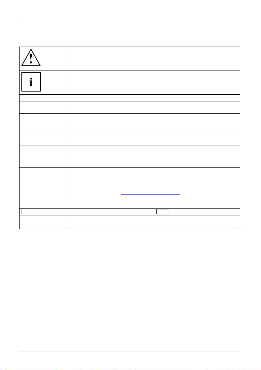
Pay particular attention to text marked with this symbol. Failure to observe
these wa rnings could pose a risk to health, damage the device or lead
to loss of data. The warranty will be invalidated if the device becomes
defective through failure to observe these warnings.
Indicates important informa
tion for the proper use of the device.
►
This font
This font
This font
"This font"
Key
This font
Indicates an activity that must be performed
Indicates a result
indicates data entered
the command line, e.g.
start a program (star
indicates information that is displayed on the screen by a program, e.g.:
Installation is complete.
indicates
• terms and texts used in a software interface, e.g.: Click on Save
• names of programs or files, e.g. Windows or setup.exe.
indicates
• cross-references to another section, e.g. "Safety information"
• cross-references to an external source, e.g. a web address: For more
information, go to "
• Names of CDs, DVDs and titles or designations for other materials,
e.g.: "CD/DVD Drivers & Utilities" or "Safety/Regulations" manual
indicates a key on the keyboard, e.g:
indicates terms and texts that are emphasised or highlighted, e.g.: Do
not switch off the device
using the keyboard in a program dialogue or at
your passwor d (Name123) or a command used to
t.exe)
http://www.fujitsu.com/fts"
F10
8 Fujitsu
Page 13
Ports and operating elements
Ports and operating elements
Ports
This chapter presents the individual hardware components of your device. This will provide
you with an overview of the ports and operating elements on the device. Please familiarise
yourself with these components before starting to work with your device.
Front
The device is available i
• device variant with bay
• device variant with bay for a slimline drive
• device variant with bl
n 3 device variants:
s for a slimline drive and a 3½ inch drive
anking plate
In the illustration
shown, that is the de
between the indivi
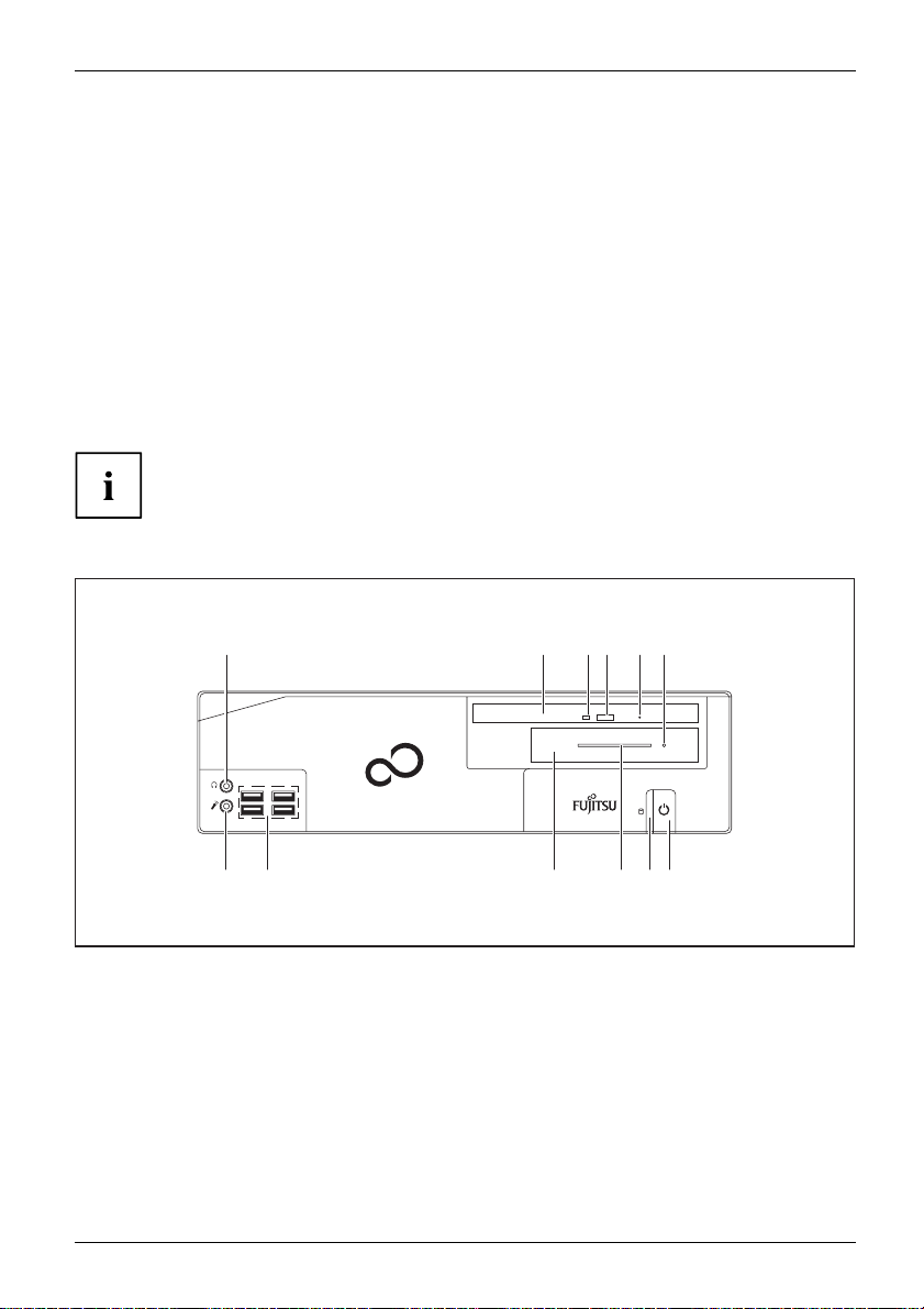
Device variant with bays for a slimline drive and a 3½ inch drive (maximum configuration level)
1 2 3 4 5 6
12
1 = Headph
2 = Bay for slimline drive
3 = Sliml
4 = Slimline drive insert/eject button
5 = Slim
6 = 3½ inch drive status indicator, e.g.
7=ON/
one port
ine drive status indicator
line drive emergency removal
SmartCard reader
OFF switch with power indicator
s in the following chapter, the maximum configuration level is always
vicevariantwithaslimlinedriveanda3½inchdrive.Anydeviations
dual device va riants are separately indicated in the particular chapters.
ESPRIMO
11 8 7910
8=Harddi
9 = Card slot on 3½ inch drive, e.g.
10 = Bay fo
11 = USB ports
12 = Micr
sk indicator
SmartCard reader
r 3½ inch drive, e.g. SmartCard
r (external), hard disk (internal)
reade
ophone port
Fujitsu 9
Page 14

Ports and operating elements
Rear
1 82 3 4
14 13 3 11 12 11 910
1 = Monitor socket (op
2 = Eye for lead-seal or padlock
(diameter 6 mm)
3 = Serial port (op
4=4slotsforlow-profile b oards or port
expansions (VGA, parallel port, eSATA)
5 = LAN port
6 = PS/2 mouse port
7 = Audio input (
tional)
tional, above: 2nd optional)
Line In), light blue
5 6
7
8 = Security lock devi
9 = Audio output (Line Out), light green
10 = PS/2 keyboard por
11 = USB ports
12 = Display ports (
13 = DVI-D monitor port
14 = Alternating v
ce
t
above: 2nd optional)
oltage socket (AC IN)
10 Fujitsu
Page 15

Important notes
ImportantnotesNotes
In this chapter you will find information regarding safety which it is essential to
take note of when working with your device.
Safety information
SafetyinformationNote
Please note the informat
and in the following safe
When installing and ope
environmental conditi
as the instructions in C
When setting up the dev
thecasingreceives
cover the ventil ati
You must only opera
device is set to the
TheON/OFFswitchd
voltage. You must
completely disco
Operate the dev
Replace the lit
in "
Replacing t
Caution, comp
The activiti
performed wi
Repairs to th
Incorrect r
to the equi
hium battery on the mainboard in accordance with the instructions
he lithium battery", Page 75.
onents in the system can get very hot.
es described in these instructions must always be
th the greatest care.
e device must only be performed by qualified technicians.
epairs could put the user at great risk or cause serious damage
pment (electric shock, risk of fire).
ion provided in the "Safety/regulations" manual
ty notes.
rating the device, please observe the notes on
ons in Chapter "
hapter "
Tec hnical specification", Page 76 as well
Getting started", Page 15.
ice, make sure there is clearance all around it so that
enough ventilation. I n order to avoid overheating, do not
on areas of the monitor or the device.
te th e device if the rated voltage used by the
local mains voltage.
oes not disconnect the device from the mains
remove the mains plug from the mains socket to
nnect from the mains voltage.
ice only with the casing closed.
Important notes
Transpor
rtation
portation
Device,Transpo
Retrans
ting the device
Transport all parts separately in their original packaging or in a packaging which
protects them from knocks and jolts, to the new site.
Do not unpack them until all transportation manoeuvres are completed.
If the device is brought from a cold environment into the r oom where it will b e used,
condensation may occur. Before operating the device, wait until it is absolutely dry
and has reached ap proximately the same temperature as the installation site.
Fujitsu 11
Page 16

Important notes
Cleaning the device
Device,TransportationRetransportationSystemunit,see Device
Turn off all power and equipm ent switches and disconnect the power
plug from the m ains outlet.
Do not clean any interior parts yourself, leave this job to a service technician.
Do not use any cleaning agents that contain abrasives or may corrode
plastic (alcohol, thinner or acetone).
Never clean the device with water! Water entering into the device could
present a serious risk to users (e.g. electric shock).
Ensure that no liquid enters the system.
The surface can be clea
moistened in mild dome
Use disinfectant wi
ned with a dry cloth. If particularly dirty, use a cloth that has been
stic detergent and then carefully w rung out.
pes to clean the keyboard and the mouse.
Energy saving, disposal and recycling
DisposalEnergysavingRecyclingDrivers&UtilitiesDVDUserDocumentationDVD
You c an findinformationonthesesubjectsinthe"Environment and Energy Information" manual
or on our website ("
http://www.fujitsu.com/fts/about/fts/environment-care/").
12 Fujitsu
Page 17

Important notes
CE marking
CEmarkingCEmarkingNotesElectromagneticcompatibilityLowvoltagedirective
The shipped version of this device complies with the requirements of EU directives 2004/108/EC
"Electromagnetic compatibility", 2006/95/EC "Low voltage directive", 2011/65/EC "RoHS directive"
and 2009/125/EC "ecodesign directive".
CE marking for devices with radio component
This equipment complies with the requirements of Directive 1999/5/EC of the European Parliament
and C ommission from 9 March, 1999 governing Radio and Telecommunications Equipment
and mutual recognition of conformity.
CE nnnn (!) ; nn nn: For digits and exclamation mark (!), see label on the product.
You ca n find more information and declarations of conformity on the Internet at:
http://globalsp.ts.fujitsu.com/sites/certificates".
"
This equipment can be used in the following countries:
Belgium Bulgaria Denmark
Estonia Finland France
UK Ireland Iceland Italy
Croatia
Latvia Liechtenstein Lithuania
Luxembourg Malta Netherlands Norway
Austria Poland Portugal Rumania
Sweden Switzerland Slovakia Slovenia
Spain
Turk ey
Czech Republic
Cyprus
Contact th
possible o
the corres
your coun
e corresponding government office in the respective country for current information on
perating restrictions. If your country is not included in the list, then please contact
ponding supervisory authority as to whether the use of this product is permitted in
try.
Germany
Greece
Hungary
Fujitsu 13
Page 18

Important notes
FCC Compliance Statement
If the device complies with the FCC regulations, the FCC sign can be found on the type rating plate.
FCC Class B Compliance State
DOC (INDUSTRY CANADA) NOTICES
Notice to Users of Radios and Television :
This class B digital apparatus complies with Canad ian ICES-003.
The following statement applies to the products covered in this manual, unless otherwise specified
herein. The statement for other products will appear in the accompanying documentation.
NOTE:
This equipment has been tested and found to com ply with the limits for a "Class B" digital
device, pursuant to Part 15 of the FCC rules and meets all requirements of the Canadian
Interference-Causing Equipment Standard ICES-003 for digital apparatus. These limits are
designed to provide reasonable protection against harmful interference in a residential installation.
This equipmen t generates, uses and can radiate radio frequency energy and, if not installed
and used in strict accordance with the instructions, may cause harmful interference to radio
communications. However, there is no guarantee that interference w ill not occur in a particular
installation. If this equipment does cause harmful interference to radio or television reception,
which can be determined by turning the equipment off and on, the user is encouraged to
try to correct the interference by one or more of the following measures:
• Reorient or relocate the receiving antenna.
• Increase the s
• Connect the equipment into an outlet on a circuit different from that to
which the receiver is connected.
• Consult the d
Fujitsu not responsible for any radio or television interference caused by unauthorized modifications
of this equipment or the substitution or attachment of connecting cables and equipment other
than those specified by Fujitsu. The correction of interferences caused by such unauthorized
modification, substitution or attachment will be the responsibility of the user.
The use of shielded I/O cables is required when connecting this equipment to any and all optional
peripheral or host devices. Failure to do so may violate FCC and ICES rules.
eparation between equipment and the r ece iver.
ealer or an experienced radio/TV technician for help.
ment
FCC Radiation Exposure Statement
This equipment complies with FCC radiation exposure limits set forth for an uncontrolled environmen t.
The transmitters in this device must not be co-located or operated in conjunction
with any other antenna or transmitter.
To prevent radio interference to the licensed service, this device is intended to be
operated indoors and away from windows to provide maximum shielding. Equipment (or
its transmit antenna) that is installed outdoors is subject to licensing.
Users are not authorized to modify this product. Any modi fications invalidate the warranty.
This equipment may not be modified, altered, or changed in a ny way without signed
written permission from Fujitsu. Unauthorized modification will void the equipment
authorization from the FCC and Industry Canada and the warranty.
14 Fujitsu
Page 19

Getting started
Getting started
Gettingstarted
Unpacking and checking the delivery
It is recommended not to throw away the original packaging material! It may be
required for reshipment at some later date.
PackagingContentsofdeliveryPackaging,
► Unpack all the individual parts.
► Check the contents of the package for any visible damage caused during transport.
► Check whether the delivery conforms to th e details in the delivery note.
► Should you discover that the delivery does not correspond to the delivery
Steps for initial setup
Preparingforfirstuse,overvie wPreparingforuse,
Only a few steps are necessary to put your new device into operation for the first time:
• Select a location for device and set up device
• Connect external devices such as mouse, keyboard and monitor
• Check the voltage at the mains outlet and connect the device to an electrical outlet
• Switch the device on
You will learn more about the individual steps in the following sections.
Please observe the safety information in the "Important notes", Page 11 chapter.
note, notify your local sales outlet immediately.
External devices
If you have received other external devices in addition to your own device (e.g.
a printer), do not connect these until after the initial installation. The following
sections describe how to connect these external devices.
Drives and boards
If you have received drives or boards with your device, please do not install
them until after first-time setup. How to install drives and boards is described
System expansions", Page 34 chapter.
in the "
Fujitsu 15
Page 20

Getting started
Setting up the device
VideoworkstationErgonomicDevice,
When setting up your device, please read the recommendations and
safety notes in the "Safety/regulations" manual.
We recommend that you place your device on a surface with good anti-slip qualities.
In view of the multitude of different finishes and varnishes used on furniture, it is
possible that the rubber feet will mark the surface they stand on.
Depending on the location of your device, bothersome vibrations and noises may
occur. To prevent this, a distance of at least 10 mm / 0.39 in should be maintained
from other devices on casing sides without ventilation surfaces.
In order to avoid overheating, do not cover the ventilation areas
on the monitor or the device.
A minim um distance of 200 mm / 7.87 in from the device must be
observed for ventilation areas.
Do not stack several devices on top of each other.
Do not expose the device to extreme ambient conditions (see "
Page 76, "Ambient conditions"). Protect the device against dust, humidity and heat.
Technical specification",
Operating positi
You can use the de
With the aid of s
(see "
Vertical
on
vice in a vertical or horizontal operating position.
uitable feet, it is possible to use the device in a vertical operating position
operating position with feet (optional)", Page 16).
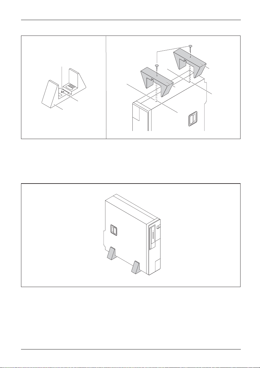
Vertical operating position with feet (optional)
Use the optional feet when you wish to use the device in the vertical operating position.
The set-up direction is compulsory: The ON/OFF switch must be at
the top to ensure sufficient ventilation.
You must remove the feet again to be able to open the device.
VerticaloperatingpositionOperatingposition,verticalBasefeetSidecover
Proceed as follows to operate the device in the vertical operating position with the feet:
► If necessary, disconnect the cables connected to the device.
16 Fujitsu
Page 21
Getting started
5
1
4
2
3
► Place the device on the right side as shown.
The screw holes ( 6)
left side of the dev
► Place the feet (3) on the left side of the device so that the pins (2) enter into the corresponding
guide openings (4) on the device and the screws rest against the screw holes (6).
► Tighten the scr
and g uide openings (4) for securing the feet on the
ice point upwards.
ews to secure the feet.
4
3
6
3
6
► Stand
Fujitsu 17
the device on the feet as shown.
Page 22

Getting started
Connecting the device to the mains supply
Mainsadapter
Use the following table to check which mains plug applies for your country. The
following illustration may be different from your country variant.
1
2
► Connect the pow
er cable to the device (1).
► Plug the power plug into a grounded mains outlet (2).
Power connection
Country
USA, Canada, Mexico, parts of South America,
Japan, Korea, the Philippines, Taiwan
Russia and the Commonwealth of Independent
States (CIS), large parts of Europe, parts of
South America, the Middle East, parts of Africa,
Hong Kong, India, large parts of South Asia.
UK, Ireland, Malaysia, Singapore, parts of Africa
China, Australia, New Zealand
18 Fujitsu
Page 23

Getting started
LAN
Connecting external devices
Read the documentation on the external device before connecting it.
With the exception of USB devices, always remove all power plugs
before connecting external devices!
Do not connect or disconnect cables during a thunderstorm.
Always take hold of the actual plug. Neve r unplug a cable by pulling the cable itself.
Ports on the device
InterfacesExternaldevices,Device ,
The ports are located on the front and back of the device. The ports available on your
device depend on the configuration level you have selected. The standard ports are
marked with the symbols shown below (or similar). Detailed information on the location
of the ports is provided in the manual for the mainboard.
Headphones, black or light
green
Headphonesport
Audio input (Line In), light blue
AudioinputLineIn
Microphone port, black or pink
Microphoneport
USB 3.0 - Universal Serial
Bus, blue
ialBus
UniversalSer
PS/2 mouse port, green
MouseportPS/2mouseport
DVI-D monitor port
DVI-Imonitorport
VGA monitor port, blue
Monitorport
Serial port
Serialinterface
DP DisplayPort
Audio output (Line Out), light green
AudiooutputLineOut
USB 2.0 - Universal Serial Bus, black
PS/2 keyboard port, purple
Keyboardport
DisplayPort
LAN port
LANport
Parallel port
Parallelport
Some of the connected devices require special drivers (see the
documentation for the connected device).
Fujitsu 19
Page 24

Getting started
Connecting a monitor
► Follow the instructions conta ined in the monitor manual to prepare the monitor
for operation (e.g. connecting cables).
Monitor
► Connect the data cable of the monitor into the required monitor port of your device.
The monitor connector on the device is only approved for use with monitors that
have a rated current less than or equal to 1.0 A at 230 V or less than or equal to
2.0 A at 100 V. The values for the monitor current consumption can be found in the
technical data for the monitor or in the operating manual for the monitor.
► Depending on the configur
cable into the grounded
ation level of your device, plug the mo nitor power
mains outlet.
Connecting the mouse
You can connect a US B mouse or a PS/2 mouse to y our device.
Mouse,Conne cting,
Connecting a USB mouse
► Connect the USB mouse to one of the USB ports on the device.
USBport,USBport
Connecting a PS/2 mouse
The PS/2 mouse is only detected by the device if you connect the mouse when
the device is switched off and then switch the device on again.
► Connect the PS/
PS/2mouse,Connecting,PS/2mouse,
► Switch your device on again.
2 mouse to the PS/2 mou se port of the device.
20 Fujitsu
Page 25

Getting started
Connecting the keyboard
You can connect a USB keyboard or a PS/2 keyboard to your device.
Keyboard,Connecting,
Connecting a USB keyboard
Use the supplied keyboard cable only.
USBport,Connecting,
► Insert the flat rectangular USB plug of the keyboard cable into one of the device’s USB ports.
USBport
Connecting a PS/2 keyboard
Use the supplied keyboard cable only.
ard
ConnectingaPS/2keybo
Connecting,
► Switch your device off.
► Plug the round plug of the keyboard cable into the keyboard port on the device.
► Switch your device on again.
Connecting external devices to the serial interface
SerialinterfaceSerialinterface,Externaldevices,Devices,
External d evices (e.g. a printer or scanner ) can be connected to the serial port.
► Connect the data c able to the external device.
► Connect the data cable to the corresponding serial interface.
The PS/2 k eyboard is only detected by the device if you connect the keyboard
when the device is switched off and then switch the device on aga in.
Keyboard,
For an exact description of how to conne ct external devices to the corresponding
port, please see the external device documentation.
Port settings
rface,
Serialinte
You can change the port settings (e.g. address, interrupt) in the BIOS Setup.
Device drivers
Devicedrivers,
Fujitsu 21
The devices connected to the serial interface require drivers. Your operating system
already includes many drivers. If the required drive is missing, install it. The latest
drivers are usually available on the Internet or will be supplied on a data carrier.
Page 26

Getting started
Connecting external devices to the USB ports
USBdevices,USBport,Externaldevices,Devices,
You can connect a wide range of external devices to the USB ports (e.g.
printer, scanner, mouse or keyboard).
USB devices are hot-pluggable. Th is means you can connect and disconnect
USB cables while your device is switched on.
Additional information can be found in the documentation for the USB devices.
► Connect the data cable to the external device.
► Connect the data cable to one of the USB ports on your device.
Device drivers
The external USB devices you connect to the USB ports usually require no driver of their
own, as the required software is already included in the operating system. If the device
requires separate software, please note the information in the manu facturer’s manual.
Switching on for the first time: installing the software
Installing,Software,Installing,
Once the installat
off, unless the in
During installa
The installati
of the hard disk
ion has been started the device must not be switched
stallation has been completed.
tion, the device may only be rebooted when you are requested to do so!
on will otherwise not be carried out correctly and the contents
must be completely restored.
If the device is integrated into a network, the user and server details as well as
the network protocol are required during the sof tware installation.
Contact your network administrator if you have any questions about these settings.
When you switch on the device for the first time, the supplied software
is installed and configured. Plan a reasonable amount of time for this,
as this process must not be interrupted.
You may need the licence number for Windows during the installation. You can find the licence
number as a label on your device ( no longer applies to Windows 8 or higher).
22 Fujitsu
Page 27

Switch on the m on itor and the machine
In order to avoid overheating, do not cover the ventilation areas
on the monitor or the device.
► Switch on the monitor (see operating instructions for the monitor).
► Press the on/off button on the front of the machine.
The operational display will light up and the machine will start.
Getting started
Installing the software
► During inst
Software,Installing,
► If anything is unclear regarding the data you are asked to input, read the
online Help in your operating system.
Fujitsu 23
allation, follow the on-screen instructions.
You wil l find more information on the system, a s well as drivers, utilities and updates on
the "Drivers & Utilities" DVD and on the Internet at "
You c a n find information and help on the Windows operating system functions
on the Internet at "
http://windows.microsoft.com".
http://www.fujitsu.com/fts/support".
Page 28

Operation
Operation
Switch the device on
► If necessary, switch the monitor on (see the operating manu al for the monitor).
DeviceMonitor
► Press the ON/OFF switch on t
The power indicator glows and the device is started.
Switching off the device
Switching the device o
disconnect the mains
► Shut down the operating system in the proper way.
DeviceMonitor
The devices switches to power saving mode automatically and switches off.
he front of the device.
ff does not disconnect it from the mains voltage. To completely
voltage, remove the power plug from the power socket.
Procedureinane
If the device cann ot be switched off, you can force a shutdown by
using the following emergency procedure.
Warning, this could lead to a loss of data!
► Press the ON/OFF switch for at least 4 seconds.
The device will switch off.
When you next restart the device, error messages may be displayed
due to the improper shutdown.
mergency
24 Fujitsu
Page 29

Operation
Indicators on the device
Indicators,Device
The indicators are o n the front of the casin g. Which indicators are available on your
device depends on the configuration level you have selected.
4
3
2
1
No. Indicator Description
1 Drive indicator
(depending on device
variant):
2 Hard disk indicator The indicator lights up when the hard disk drive in the device
3 Power-on indicator
4
Indicator for optional
components, e.g.
SmartCard reader
(depending on the
device variant)
The indicator lights up when the CD-ROM or DVD drive in the
device is accessed. Never under any circumstances remove the
CD/DVD while the indicator is lit.
is being accessed.
Caution: In e
disconnecte
nergy-saving mode, the device must n ot be
d from the mains supply, as this could lead to loss
of data.
• The indica
tor is illuminated:
The device is switched on.
• The indic
ator is flashing:
The device is in energy-saving m ode. After being switched on
with the ON/OFF switch, the device powers up or returns to the
state it was in before it entered energy-saving mode.
•Theind
icator is not lit:
The device is switched off.
The indicator lights up when optional components, e.g. S martCard
reader, are accessed.
Fujitsu 25
Page 30

Operation
Keyboard
KeyboardKeyboard,Ke yboard,Keyboard,Keyboard,Keyboard,AlphanumerickeypadCursorkeysKeys,Function key sNum er ickeypadNumerickeypad
The illustrated keyboard is an example and may differ from the model you use.
1 2
345
1 = Function keys
2 = On/off switch (optional)
4=Cursorkeys
5 = Numeric keypad (calculator keypad)
3 = Alphanumeric keypad
Important k
KeysKeyb oardshortcuts
eys and keyboard shortcuts
The description of the following keys and keyboard shortcuts applies to Microsoft
operating systems. Details of other keys and keyboard shortcuts can be found in
the documentation for the relevant application program.
Key / key combination Description
tch
ON/OFFswi
Button,
On/off switch (optional)
Depending on the setting in the BIOS Setup, the device can be switched
on or off with this switch. Some operating systems allow you to configure
additional functions of the ON/OFF switch in the Control Panel.
WithsomekeyboardstheON/OFFswitchcanonlybeusedwithanACPI
(Advanced Configuration and Power Manageme n t Interface). Otherwise
the key is inoperative. The m ainboard must support this function.
Keys,Keys,Keys,
Enter key
confirms the highlighted selection. The Enter key is also referred to as
the "Return" k ey.
26 Fujitsu
Page 31

Operation
Key / key combination Description
Keys,
Windows key (device-dependent
calls up the Windows Start menu
Keys,
Menu key (device-dependent:
calls up the menu for the marke
Keys
Windows key (device-depe
Switches between the star
Keys
Menu key (device-dependent: variant 2)
Opens the menu for the active application.
Keys,Keys,
Shift key
enables upper-case
Keys,
Alt Gr key (country
produces a charac
sign on the
Keys,
Num Lock key
By pressing the
lower-case lev
When the Num Lo
keys are activ
When the Num L
Numeric keyp
Keys,KeysKeysKeys,
Ctrl key
Ctrl
performs a special operation when pressed in conjunction with another
key. The
Ctrl+Alt+DelCtrl+Alt+DelKeyskeyboardshor tcuts
Ctrl
Windows Security/Task Manager
AltCtrl
++
Del
This key combination op ens the Windows Security/Task Manager window.
:variant1)
.
variant 1)
d item (Windows).
ndent: variant 2)
t screen and the last used application.
letters and the upper key symbols to be displayed.
-dependent)
ter shown on the bottom right of a key (e.g. the @
Q
key).
Num Lock key you switch between the upper- and
els of the calculator keypad.
ck indicator is lit the numeric keypad and arithmetic
e.
ock indicator is not lit the cursor control functions on the
ad are active.
key is a lso called the "Control" or "Control key".
Settings in BIOS Setup
etup,
msettings,
etup,
etup,
etup
,
BIOSS
Syste
BIOSS
BIOSS
BIOSS
Setup
In BIOS Setup, you can set the system functions and the hardware configuration of the device.
When the PC is delivered, the default entries are valid (see "BIOS Setup" manual or manual for
the mainboard). You can customise these settings to your requirements in the BIO S Setup.
Fujitsu 27
Page 32

Operation
Property and data protection
PropertyprotectionData pr otectionSecuritymeasures
Software functions and mechanical locking offer a broad range of functions for protecting your device
and your personal data against theft and una uthorised access. You can also combine these functions.
Mechanically protecting and l ocking the casing
Your device has provision for a security lock (4). Using the security lock provision and
the Kensington Lock cable (steel cable, accessory) you can protect your device against
theft. Please consult the manual for your Kensington Lock.
To prevent unauthorised persons from opening the casing, the casing can be sealed (1) or i t can
be secured with a padlock. To do this, feed the sealing chain through the eye (2) and seal the
chain with the lead seal. Alternatively, pass a suitable padlock through the eye (2).
Lead-sealingAnti-theftprotectionSecurityLockChainPadlockProtect
2
3
1
4
2
1 = Lead seal
2 = Eye for padlock / lead seal (diameter 6 mm)
3 = Casing lock (optional)
4 = Provision for security lock
With the casing lock (3) you can mechanically lock the casing to prevent unauthorised persons
from opening it. The keys can be found at the rear of your device.
In addition to the casing lock, an open andaclosedlock are also illustrated.
• Key turned towards the closed lock: The device is locked.
• Key turned towards the open lock: The device is not locked.
Locking the casing
► Turn the key towards the closed lock .
28 Fujitsu
Page 33

Unlocking the casing
► Turn the key towards the open lock .
BIOS setup security functions
SecurityfunctionsBIOS Setup
The Security menu in BIOS S
personal data against un
• Prevent unauthorized ac
• Prevent unauthorised syste m access
• Prevent unauthorised a
• Activate virus warnings
• Protect BIOS from ove
• Protect the device from being switched on by an external device
You can also combin
You will find a detai
in the manual for t
Access authorisation via SmartCard
ions
ion,SmartCard
Securityfunct
Accesspermiss
led description of the Security menus and how to assign passwords
he mainboard or in the "BIOS Setup" manual.
In systems equipped with a SmartCard reader, access can be restricted to those
users who have a corresponding SmartCard.
etup offers you various options for protect ing your
authorized access, e.g.:
cess to BIOS Setup
ccess to the settings of boards with their own BIOS
rwriting
e these functions.
Operation
Operating the SmartCard reader (optional)
Operation of a SmartCard reader with a RFID reader is not permitted in Taiwan.
► Connect the external SmartCard reader to your system as described in
the instructions for the SmartCard reader.
SmartCardreader,
After the device is switched on, you will be prompted to insert your SmartCard.
Fujitsu 29
Page 34

Problem solutions and tips
Problem solutions and tips
Refer to the safety notes in the "Safety/regulations" manual and in the "Getting
started", Page 15 chapter when connecting or disconnecting cables.
If a fault o ccurs, try to r
• in this chapter
• in the documentation relating to the peripheral devices
• in the Help sections fo
• in the documentation for the operating system in use.
ectify it in accordance with the measures described in the following documents:
r the individual programs
Help if problems occur
Should you encoun
► Note the ID nu mber
plate on the back
► For further clarification of the problem, contact the Service Desk for your country (see the
Service Desk list or visit the Internet at "
you do this, please have ready the identity number and serial number of your system.
ter a problem with your computer that you cannot resolve yourself:
of your device. The ID number is found on the type rating
, the underside or the top of the casing.
http://support.ts.fujitsu.com/contact/serv icedesk"). When
Troubleshooting
Power-on indicator remains unlit after you have switched on your device
Cause
The mains voltage supply is faulty. ► Check whether the power cable is plugged
Internal power supply overloaded.
Troubleshooting
properly into the device and a grounded
mains outlet.
► Pull the power plug o f the device out of the
mains outlet.
► Wait app
► Plug the power plug into a properly grounded
mains outlet again.
► Switc
rox. 3 min.
h the device on.
30 Fujitsu
Page 35

Problem solutions and tips
The device cannot be switched off with the ON/OFF switch.
Cause
System crash ► Keep the on/off switch pressed for at least 4
Remedy
seconds until the machine switches off.
Caution: This can lead to a loss of data!
This procedure does not allow the operating
system to shut down in an orderly way. The next
time the system is started there may well be
error messages.
Monitor remains blank
Cause
Monitor is switched off ► Switch your monitor on.
Power saving has been activated (screen is
blank)
Brightness control is set to dark ► Adjust the brightness control. For detailed
Power cable not connected
Monitor cable not connected
Incorrect setting for the monitor
Remedy
► Press any key on the keyboard.
or
► Deactivate the screen saver. If
necessary, enter the appropriate
password.
information, please refer to the operating
manual supplied with your monitor.
► Switch off the monitor and the device.
► Check that the monitor power cable is
properly connected to the monitor and to
a grounded mains outlet or to the monitor
socket of the device.
► Check that the device power cable is
properly plugged into the device and a
grounded m ains outlet.
► Switch on the monitor and the device.
► Switch of
► Check that the monitor cable is properly
connected to the device and monitor.
► Switch o
► Restar
► Press
► Start
► Set up the monitor as described in the
documentation for your operating system
and monitor.
f the monitor and the device.
n the monitor and the device.
t the system.
8
F
while the system is booting.
the system in Safe Mode.
Fujitsu 31
Page 36

Problem solutions and tips
No mouse pointer displayed o n the screen
Cause
The mouse is not correctly connected.
Disabled USB ports ► In the BIOS Setup, check whether the USB
Remedy
► Shut down your opera ting system in the
proper m anner, for instance using
Alt+Del
► Switch the device off.
► Check that the mouse cable is properly
connected to the system unit. If you use an
adapter or extension lead with the mouse
cable, check the connections.
► Make sure that only one mouse is
connected.
► Switch the device on.
ports are Enabled (see the "BIOS Setup"
manual or the mainboard manual
.
Ctrl
Time and/or date is not correct
Cause
Time and date are incorrect.
The lithium battery is discharged.
Remedy
► Set the correct ti
operating syste
or
► Set the correct time and/or date in the
BIOS Setup.
► If the time and
when you switc
lithium batt
battery", P
me and date within the
m you are using.
date are repeatedly wrong
h on your device, replace t he
ery (see "
age 75).
Replacing the l ithium
+
SmartCard
Cause
Chip card inserted incorrectly.
32 Fujitsu
reader is not recognised.
Troubleshooting
► Make sure you have inserted your
SmartCard into the SmartCard reader with
the chip facing upwards.
► Check whether the SmartCard you are using
is supported. Your SmartCard must comply
with the ISO standard 7816-1, -2, -3 and -4.
Page 37

Problem solutions and tips
SmartCard PIN forgotten
Cause
PIN forgotten ► If you are working in a network, contact your
Troubleshooting
system administrator, who can unlock your
system with a Supervisor PIN.
Error messages on the screen
Error messages and their explanations are provided:
• in the technical manual for the mainboard
• in the documentation for the programs used
Installing new software
When installing programs or drivers, important files may be overwritten and modi fied. To
be able to access the original data in the event of any problems following installation,
you should backup your hard disk prior to installation.
Restoring the hard disk contents
You will fin d the instructions for restoring the contents of the hard disk in the "Recovery Guide" manual.
Tips
Topic Tip
Outofsystemresources ► Close unnecessary applications.
or
► Run the appl
Other manuals Further manuals are provided as PDF files on
the "Drivers & U tilities" DVD.
Fujitsu 33
ications in a different order.
Page 38

System expansions
System expansions
Upgrades,Device,SystemexpansionComponentsServicing
After consulting the Hotline/Help Desk, you may remove and install the components
described in this manual yourself.
The following illustrations may differ slightly from your device, depending on its configuration level.
If further d ocu mentation was delivered with your device, please also read this through carefully.
In addition, before removing or installing system components, please pay attention to the following:
Repairs to the device must only be performed by qualified technicians. Incorrect repairs
may greatly endanger the user (electric shock, fire risk) and will invalidate your w arranty.
As the de vice has to be shut down in order to install/deinstall system hardware
components, it is a good idea to print out the relevan t sections of this chapter beforehand.
The device must be switched off when installing/rem oving the system
expansions and may not be in energy-saving mode.
Remove the power plug before opening the device.
Be careful that no wires become trapped when removing or installing components.
When installing components that become very hot, make sure that the maximum
permissible te mperature of the components in operation is not exceeded.
An update of the BIOS may be required for a system expansion or hardware
upgrade. Further information can be found in the BIOS help s ection or if
necessary in th e Technical Manual for the mainboard.
34 Fujitsu
Page 39

System expansions
Information about boards
Take care with the locking mechanisms (catches and centring pins) when you
are replacing boards or components on boards.
Note that some components on the mainboard may be very hot if the device was
in use shortly before the casing was removed.
To prevent damage to the board or the components and conductors on it, please take care when
you insert or remove boards. Make sure expansion boards are i nserte d straightly.
Never use sharp objects (screwdrivers) for leverage.
Boards with electrostat
shown.
When handling boards fit
following points:
• You must always disc
object) before work
• The equipment and tools you use must be free of static charges.
• Only touch or hold t
marked green (Touc
• Never touch pins or conductors on boards fitted with ESDs.
ic sensitive devices (ESD) are identifiable by the label
ted with ESDs, you must always observe the
harge static build up (e.g. by touching a grounded
ing.
he boards by the edge or, if present, at the areas
h Points).
Fujitsu 35
Page 40

System expansions
Removing the casing cover
► Switch the device off.
The device must not be in the energy-saving mode!
► If there is a foot installed, remove it.
► Remove any plugged-in wires which are in the way.
2
1
a
► Raise the clip (a), hold it in this position and pull the casing cover in the direction of the arrow (1).
► Lift the casing cover off the casing (2).
36 Fujitsu
Page 41

Reattaching the casing cover.
In order to make it easier to put on the casing cover, there a re two reference lines
(c) imprinted on the board clip, which will assist you when positioning.
2
System expansions
1
a
► Place the casing cover onto the casing (1) using the reference lines (c) for positioning
and slide the casing cover in the direction of the arrow (2) until it reaches a stop. When
doing so, make sure that the eye (b) fits into the opening (a).
Thecasingcov
move the retai
► Connect the cables to the device.
er will click into place automatically, without any need to
ning mechanism.
b
c
c
Fujitsu 37
Page 42

System expansions
Overview of drive bays and drives in your device
Depending on the device variant, the casing offers space for accessible and
non-accessible drives in the 3 bays.
Examples of accessible drives are DVD or CD ROM drives, into which a data medium
can be inserted from the outside. Examples o f non-accessible drives are hard disk drives.
Furthermore, the installation options depend on the particular drive cover
being used, see "
Changing the drive cover", Page 39.
Casing with drive cover
No. Bay Fixing Installati
a
Lower bay for
non-accessible 3½
inch drives or 2½ inch
drives
b
Middle bay for
3½ inch drives or
non-accessible 2½
inch drives with 3½
inch adapter
c
rbayforan
Uppe
ssible slimline
acce
e
driv
removed and drive cage opened:
EasyChange rails or
screw fastening
Screw fastening • 1 x accessible 3½ inch drive
e plate (screwless)
Driv
• 1 x non-accessible 3½ inch drive,
EasyChange
• 2 x non-accessible 2½ inch drives with
3½ inch adapter, EasyC hange
• 1 x non-accessible 2½ inch drive,
screw fastening
• 1 x non-accessible 3½ inch drive
• 2 x non-accessible 2½ inch drives, with
3½ inch adapter
1 x slimline drive
a
on options in bay
c
b
38 Fujitsu
Page 43

System expansions
Changing the drive cover
Depending on the desired drive c onfi guration level of your device, there are 4 different drive covers
available: When an accessible drive is ordered, the required drive covers will be supplied with it.
1
3
1 = No slimline drive can be installed,
non-accessible drives possible
under the cover
2 = Slimline drive can be installed,
non-accessible drives possible
under the cover
Proceed as follows to replace a drive cover with another drive cover:
► Remove the casing cover (see chapter "
2
4
3 = Slimline drive and accessible 3½ inch
drive can be installed
4 = Accessible3½inchdrivecanbeinstalled
Removing the casing cover", Page 3 6).
Fujitsu 39
Page 44

System expansions
The catches of the drive cover are on the inside.
a
b
1
► First release the two middle catches (a).
► Then release the two side catches (b).
► Remove the drive cover towards t he front (1).
b
a
40 Fujitsu
Page 45

System expansions
Do not d iscard the filler panel. Depending on the desired configuration level, you m ust
reinstall the filler panel for cooling, protection against fire and in order to comply with EMC
(electromagnetic compatibility) regulations (see ""
Removing a slimline drive", Page 45").
a
b
2
b
a
► Insert the new drive cover into the casing cover from the front. In doing so, make
sure that all the inner catches that are present enga ge (a, b).
► Change the desired drives as required, as described in the corresponding chapter.
► Fit the casing cover onto the casing again (see chapter "
Reattaching the casing cover.", Page 37).
Fujitsu 41
Page 46

System expansions
Installing and removing an acce
ssible slimline
drive in the upper bay (optional)
Installing the drive plate for the slimline drive
To use the locking function of the accessible slimline drive, you must fit the associated drive plate
on the slimline drive before installing the drive in the casing. Proceed as follows:
The drive plate is located in the upper bay for the slimline drive.
► Remove the casing cover (see Chapter "
Removing the casing cover", Page 36).
1
1
a
2
► Press the clip in the direction of the arrow (1).
► Remove the drive plate (a) from the upper bay (2).
42 Fujitsu
Page 47

3
► Secure the drive plate on the slimline drive as shown (3).
System expansions
Fujitsu 43
Page 48

System expansions
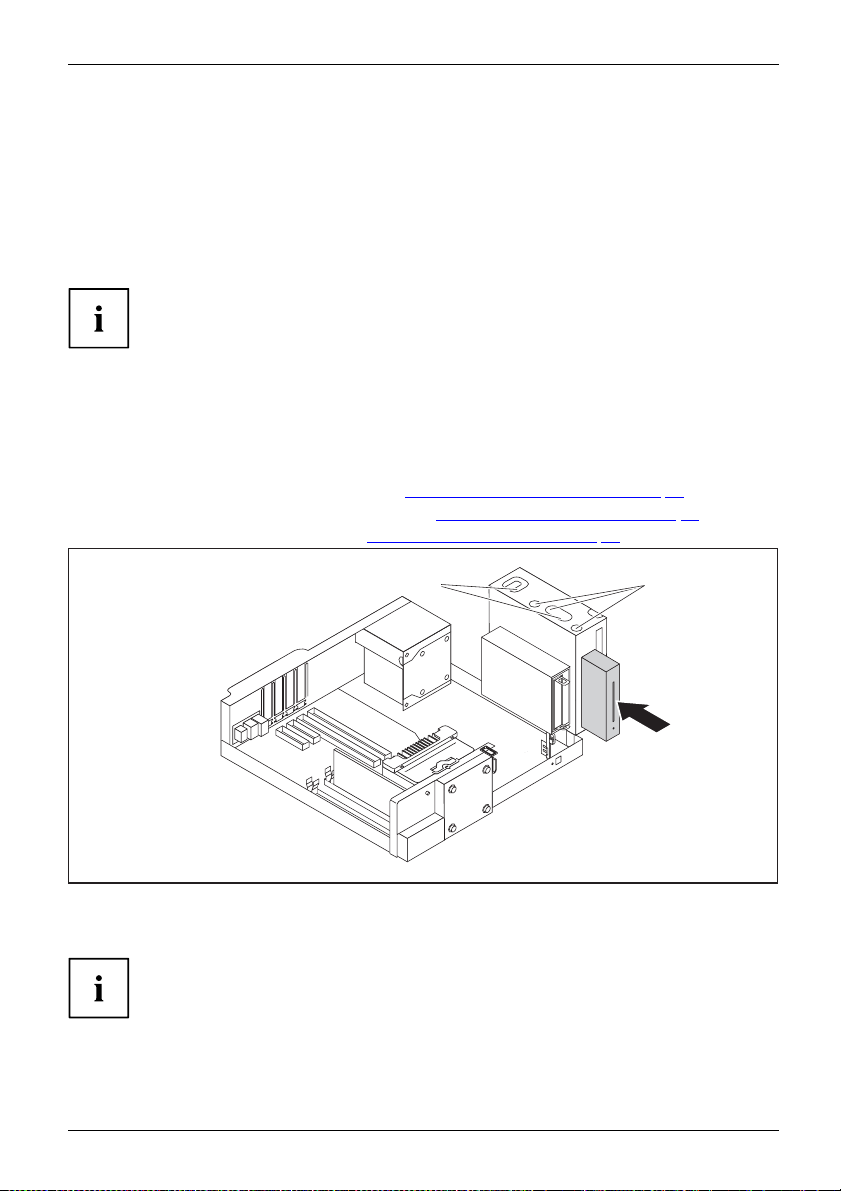
Installing a slimline drive
• The drive plate is attached to the slimline drive (see chapter "Installing th e
drive plate for the slimline drive", Page 42).
• A suitable drive cover is mounted (see chapter "
Changing the drive cover", Page 39).
1
► Slide the sliml
► Connect the cables to the slimline d rive and to the mainboard. Make sure the polarity is correct.
► Fit the casing
44 Fujitsu
ine drive into its bay in the direction of the arrow (1) until it engages in place.
cover back onto the casing (see Chapter "
If necess ary,
you must adjust the entry for the drive accordingly in the BIOS Setup.
Reattaching the casing cover.", Page 37).
Page 49

System expansions
Removing a slimline drive
► Remove the casing cover (see Chapter "Removing the casing cover", Page 36).
► Disconnect the cables connected to the slimline drive.
2
► Press the clip in t
► Push the slimline drive a few centimetres out of the bay in the direction of the arrow (2).
► Pull the slimli
he direction of the arrow (1).
ne drive completely out of the bay in the direction of the arrow (3).
4
1
3
► Detac
Fujitsu 45
h the drive plate from the slimline dri ve (4).
Page 50

System expansions
1
5
► Slide the drive plate (a) into the upper bay (5) again as shown, until it engages.
It is essential to ensure that the drive plate is installed in the correct
installation direction (see illustration).
► If you are not in
chapter "
► Fit the casing cover back onto the casing (see Chapter "
If necessary, you must adjust the entry for the drive accordingly in the BIOS Setup.
stalling a new slimline drive, change the drive cover (see
ing the drive cover", Page 39).
Chang
Reattaching the casing cover.", Page 37).
a
46 Fujitsu
Page 51

System expansions
Opening and closing the drive cage
To be able to install and remove drives in the middle and lower bays, it is
necessary to fold the drive cage upwards.
Opening the drive cage
► Remove the casing cover (see chapter "Removing th e casing cover", Page 36).
2
1
a
► Press the release (a) in the direction of the arrow (1).
► Fold the drive cage fully open (2) until it locks in place.
Fujitsu 47
Page 52

System expansions
Closing the drive cage
2
1
a
► Gently press the upright bracket (b) of the drive cage in the direction of the
arrow (1) until you can move the drive cage.
When closing the drive cage, take care that no cables become trapped and
that the release catch (a) of the drive cag e engages again.
► Fold the drive cage in the direction of the arrow ( 2).
► Fit the casing cover onto the casing again (see chapter "
b
Reattaching the casing cover.", Page 37).
48 Fujitsu
Page 53

System expansions
Installing and removing 2½ inch drives in a 3½ inch adapter
You can install two non-accessible 2½ inch drives with a 3½ inch adapter in the lower and middle bays.
Installing 2½ inch drives in a 3½ inch adapter
EasyChange rails for both drives are in the adapter.
a
► Fasten the EasyChange rails to the side of the first drive by inserting each pin of the
EasyChange rail in the corresponding holes on the drive. In doing so, make sure that
the ports on the drive are located at the rear as shown (a).
► Repeat the step for the second drive.
Fujitsu 49
Page 54

System expansions
b
2
1
► Slide the drives with t he EasyChange rails one after the other into the adapter (1, 2).
In doing so, make sure that the component side of the drives point down towards the
adapter and the ports on the drives are located at the rear as shown (b).
50 Fujitsu
Page 55

System expansions
Removing 2½ inch drives from a 3½ inch adapter
1
2
1
3
► Press the EasyCha
the EasyChange r
► Pull the EasyChange rails off the first drive.
► Repeat the step for the second drive.
► If you no longer need the EasyChange rails, secure them again at their location in the adapter.
nge rails on the drives slightly together (1) and pull the drives with
ails one after the other out of the adapter (2, 3).
a
Fujitsu 51
Page 56

System expansions
Installing and removing drives
in the
lower b ay (optional)
In the lower bay you can install
inch drives with a 3½ inch adap
Depending on the type of driv
Installing and removing a 3½ inch drive or a 3½ inch adapter
The following procedure describes installation and removal using the example of a 3½ inch drive.
The approach is the same for all variants. Any differences are indicated accordingly.
Installing a drive
► Remove the casing cover (see Chapter "Removing the casing cover", Page 36).
► Fold out the drive cage (see chapter "
EasyChange rails for the drive are located in the lower bay.
a
a non-accessible 3½ inch drive, two non-accessible 2½
ter or a non-accessible 2½ inch drive.
e, fixing to the casing is either by EasyChange rails or by screw fastening.
Opening the drive cage", Page 47).
► Fasten the EasyChan ge rails to the side of the drive or adapter by inserting each pin of
the EasyChange rail in the corresponding holes on the drive. In doing so, make sure
that the ports on the drive are located at the rear as sh own (a).
52 Fujitsu
Page 57

System expansions
1
► Slide the drive with the EasyChange rails into the bay (1). Check that the component side of
the drive faces downwards towards the base of the casing (with the drive cage closed).
► Connect the cables
► Fold the drive cage into the closed position again (see chapter "
► Fit the casing cov
at the drive and at the mainboard. Make sure the polarity is correct.
Closing the drive cage", Page 48).
er back onto the casing (see Chapter "
Reattaching the casing cover.", Page 37).
If necessary, y
Fujitsu 53
ou must adjust the entry for the drive accordingly in the BIOS Setup.
Page 58

System expansions
Removing a drive
► Remove the casing cover (see Chapter "Removing the casing cover", Page 36).
► Fold out the drive cage (see chapter "
► Disconnect any cables connect ed to the drive.
Opening the drive cage", Page 47).
2
► Slightly press together the EasyChange rails on the drive (1).
► Push the drive a few centimetres out of the bay in the direction of the arrow (2).
► Pull the drive completely out of the bay in the direction of the arrow (3 ).
1
1
3
► Pull the EasyChange rails off the drive.
ou no longer need the EasyChange rails, secure them again in the lower bay.
► If y
► Fold the drive cage into the closed position again (see chapter "
t the casing cover back onto the casing (see Chapter "
► Fi
54 Fujitsu
Closing the drive cage", Page 48).
Reattaching the casing cover.", Page 37).
Page 59

System expansions
It may be necessary to mo dify the entry for the drive in the BIOS Setup.
Installing and removing a 2½ inch drive (screw fastened)
Installing a drive
► Remove the casing cover (see chapter "Removing th e casing cover", Page 36).
► Fold out the drive cage (see chapter "
Opening the drive cage", Page 47).
1
2
► Slide the drive into the bay (1).
► Secure the d
► Connect the cables at the drive and at the mainboard. Make sure the polarity is correct.
► Fold the dr
► Fit the casing cover onto the casing again (see chapter "
Fujitsu 55
rive with the screws (2).
ive cage into the closed position again (see chapter "
If necessary, you must adjust the entry for th e drive accordingly in the BIOS Setup.
Closing the drive cage", Page 48).
Reattaching the casing cover.", Page 37).
Page 60

System expansions
Removing a drive
► Remove the casing cover (see chapter "Removing the casing cover", Page 36).
► Fold out the drive cage (see chapter "
► Disconnect any cables that are connected to the drive.
► Undo the screws (1).
► Push the drive a few centimetres out of the bay in the direction of the arrow (2).
► Pull the drive completely out of the bay in the direction of the arrow (3 ).
► Fold the drive cage into the closed position again (see chapter "
► Fit the casing cover onto the casing again (see chapter "
Opening the drive cage", Page 47).
3
2
1
Closing the drive cage", Page 48).
Reattaching the casing cover.", Page 37).
If necessary, you must adjust the entry for the drive accordingly in the BIOS Setup.
56 Fujitsu
Page 61
System expansions
Installing and removing drives
in the
middle bay (optional)
In the middle bay you can either
a 3½ inch adapter. Accessible
readers. Non-accessible dri
Fixture in the casing is al
Operation of a SmartCard r
The following procedure describes installation and removal using the example of a Multicard reader.
The approach is the same for all variants. Any differences are indicate d accordingly.
Installing a 3½ inch
• The casing cover is removed (see chapter "Removing the casing cover", Page 36).
• A suitable drive co
► Fold out the drive cage (see chapter "
ver is mounted (see chapter "
install one 3½ inch or two 2½ inch drives using
drives here are for example SmartCard or Multicard
ves are hard disks or SSDs.
ways using screws.
eader with a RFID reader is not permitted in Taiwan.
drive
Changing the drive cover", Page 39).
Opening the drive cage", Page 47).
a
b
1
► When installing 2.5" HDDs/SSDs or a SmartCard reader: Connect the cables
to the drive before you slide it into the b ay.
On the multicard reader, one end of the cable is already fixed to the reader.
► Slide the drive into the bay (1).
Fujitsu 57
Page 62

System expansions
The screw positions are different for n on-accessible drives and accessible drives:
• sheet metal stamping 1 (in illustration: b) valid for accessible
drives (Multicard/SmartCard reader).
• sheet metal stamping 2 (in illustration a) valid for non-accessible
drives (HDDn/SSDn, also in adapter).
► Secure the drive with the scr
ews (a or b, depending on the type of drive).
► When installing a 3½ inch hard disk: Co nnect the cables to the drive.
Make sure the polarity is correct.
► Connect the other end of t
► Fold the drive cage into the closed position again (see chapter "
► Fit the casing cover ont
If necessary, you must
he cable to the corresponding USB po rt or SATA port of the mainboard.
Closing the drive cage", Page 48).
o the casing again (see chapter "
Reattaching the casing cover.", Page 37).
adjust the entry for the drive accordingly in the BIOS Setup.
58 Fujitsu
Page 63

System expansions
Removing a 3½ inch drive
► Remove the casing cover (see Chapter "Removing the casing cover", Page 36).
► Fold out the drive cage (see Chapter "
► Disconnect any cables connected to the drive.
Opening the drive cage", Page 47).
a
1
► Undo the screws (a or b, depending on the type of drive).
► Push the drive a few centimetres out of the bay in the direction of the arrow (1).
► Pull the drive completely out of the bay in the direction of the arrow (2).
► If you are n ot installing a new drive, change the drive cover if necessary (see
chapter "
► Fold the drive cage into the closed position again (see chapter "
► Fit the casing cover onto the casing again (see chapter "
Changing the drive cover", Page 39).
Closing the drive cage", Page 48).
Reattaching the casing cover.", Page 37).
If necessary, you must adjust the entry for th e drive accordingly in the BIOS Setup.
b
2
Fujitsu 59
Page 64

System expansions
b
Installing and removing an M.2 m
odule
Installing an M.2 module
► Remove the casing cover (see chapter "Removing the casing cover", Page 36).
► Fold out the drive cage (see chapter "
► Insert the M.2 m
(1) into the slo
► Secure the M.2 module on the mainboard with the screw (2).
► Fold the drive
► Fit the casing cover onto the casing again (see chapter "
odule (b) at a slight angle in the direction of the arrow
t (a) on the m ainboard.
cage into the closed position again (see chapter "
Opening the drive cage", Page 47).
a
1
b
Closing the drive cage", Page 48).
Reattaching the casing cover.", Page 37).
2
If necessary, you must adjust the entry for the M.2 m odule accordingly in the BIOS Setup.
60 Fujitsu
Page 65

System expansions
b
Removing an M.2 module
► Remove the casing cover (see chapter "Removing th e casing cover", Page 36).
► Fold out the drive cage (see chapter "
Opening the drive cage", Page 47).
a
2
b
1
► Undo the screw (1)
► Pull the M.2 module (b) slightly at an angle in the direction of the arrow (2) and out
of the slot (a) on the mainboard and remove it from the casing.
► Fold the drive
► Fit the casing cover onto the casing again (see chapter "
If necessary, you must adjust the entry for the M.2 module accordingly in the BIOS Setup.
.
cage into the closed position again (see chapter "
Reattaching the casing cover.", Page 37).
Closing the drive cage", Page 48).
Fujitsu 61
Page 66

System expansions
Installing and removing low-profile boards
Low-profileboard
The four slots for the boards are protected by a board clip. A n additional slot cover exists for
each individual slot. If no board is installed in the slot, the slot cover protects the slot.
When you install a board, do not discard the corresponding slot cover.
For cooling, prote ction against fire and in order to comply with EMC regulations,
you must refit the slot cover if you remove the board.
Opening the board retaining mechanism
► Remove the casing cover (see Chapter "Removing the casing cover", Page 36).
► Undo the optional safety screw of the board clip, if present.
1
► Fold out the board retaining mechanism (1).
62 Fujitsu
Page 67

Removing a slot cover.
1
2
Do not throw away the slot cover. For cooling, protection against fireandinorderto
comply with E MC regulations, you must refit the slot cover if you remove the board.
System expansions
► Undo the screw (1 , optional).
► Pull the slot cover out of the slot (2).
Fujitsu 63
Page 68

System expansions
Installing a board
2
1
a
► If necessary, connect the cables to the board.
If you have installed or removed a board, please check the relevant PCI
slot settings in the BIOS Setup. If necessary, change the settings. Further
information is provided in the PCI board documentation.
► Push the board into the slot (1)
until it engages.
If present, the additional board retaining
clip (a) engages.
► Tighten the screw (2, optional).
Removing boards
► If necessary, disconnect the cables which are connected to the board.
► Undo the screw (1, o ptional).
1
2
a
64 Fujitsu
► Release the board retaining clip (a)
where applicable.
► Pull the board out of the s lot (2).
► Place the board in suitable packaging.
Page 69

Reinstalling a slot cover
2
1
System expansions
► Push the slot cover into the slot (1).
► Tighten the screw (2, optional).
Fujitsu 65
Page 70

System expansions
Closing the board retaining mechanis m
1
► Fold the board retaining mechanism to the closed position ( 1).
► If necessary, also secure the board clip with the optional safety screw when present.
► Fit the casing cover back onto the casing (see Chapter "
If you have installed or removed a board, please check the relevant PCI
slot settings in the BIOS Setup. If necessary, change the settings. Further
information is provided in the PCI board documentation.
Reattaching the casing cover.", Page 37).
66 Fujitsu
Page 71

System expansions
Installing and removing WLAN an
If you have installed a suitable low-profile board , you can install and remove the
associated WLAN antennas as described below.
tennas
Installing WLAN antennas
• A suitable low-profile board is installed (see chapter "Installing and removing
low-profile boards", Page 62).
2
3
1
► Working in the direction of the arrow (1), place the WLAN ante nnas onto
the plug-in positions of the board (2).
► Secure the WL
► Align the WLAN antennas as required.
AN antennas by turning in the direction of the arrow (3).
3
Fujitsu 67
Page 72

System expansions
Removing WLAN antennas
2
1
1
3
► Undo the WLAN antennas by turning in the direction of the arrow (1).
► Pull the WLAN antennas in the direction of the arrow (3) and away from
the plug-in positions of the board (2).
68 Fujitsu
Page 73

System expansions
Installing a serial port
Depending on the configuration level of your device, there may be a second installation opening
intended for a serial port on the rear panel of the device. As a result, no board slot is occupied.
► Remove the casing cover (see chapter "
If there is no port already installed, the installation opening is closed off by a
sheet metal plate. Do not discard the sheet metal plate. In order to comply
with the electromagnetic compatibility (EMC) regulations, you must refitthe
sheet metal plate if you remove the serial port again.
Removing the casing cover", Page 3 6).
1
2
1
► Keep the c lips (1) pressed and push the sheet metal plate out of the casing from the inside (2).
3
► Position the serial port on the inside of the device at the appropriate place (3).
Fujitsu 69
Page 74

System expansions
4
► Fasten the serial port with the screws (4).
► Connect the cable t
► Fit the casing cover onto the casing again (see chapter "
To remove, carry out the above steps in reverse order. To comply with
the electromagnetic compatibility (EMC) re gulations, secure the sheet
metal plate again at the installation opening.
o the mainboard (5).
5
Reattaching the casing cover.", Page 37).
70 Fujitsu
Page 75

System expansions
Installing and removing heat si
nks
Removing the heat sink
► Remove the casing cover (see Chapter "Removing the casing cover", Page 36).
1
2
a
► Pull the catch of the hood in the direction of the arrow (1) (identified with the label "PULL").
► Slightly tilt t
the pins (a) rel
he cowl and lift it out of the casing (2). In doing so, take care that
ease from the openings on the casing.
3
4
► Undo
► Lift the heat sink out of the casing (4).
Fujitsu 71
the screws on the heat sink (3).
Page 76

System expansions
Never operate the device without the heat sink fitted! Reinstall the
heat sink before switching on the device.
72 Fujitsu
Page 77

System expansions
Installing the heat sink
a
2
1
► Insert the heat sink into the casing (1): in doing so, align the screw holes on the heat sink
correctly together with the screw holes on the mainboard and pay attention to the sticker (a) on
the h eat sink. This must point towards the inside of the casing / away from the front of the casing.
► Tighten the screws (2) in a crosswise fashion.
3
b
► Place the cowl in the casing (3) at a slight angle and pay attention that the pins
(b) fit into the openings on the casing as shown.
The cowl engages at the location marked "PULL".
► Fit t he casing cover back onto the casing (see Chapter "
Fujitsu 73
Reattaching the casing cover.", Page 37).
Page 78

System expansions
Mainboard expansions
Details on how to upgrade the main memory or the processor of your device
can be found in the manual for the mainboard.
UpgradesLithiumbatteryProcessorMainmemoryMainboard
Upgrading main memory
► Remove the casing cover (see Chapter "Removing the casing cover", Page 36).
Mainmemory,
► Upgrade the memory according to the description in the manual for the mainboard.
► Fit the casing cover back onto the casing (see Chapter "
Processor, replacing
► Remove the casing cover
Processor,replacin g
► Remove the heat sink (see "Removing the heat sink", Page 71).
► Upgrade the processo
► Reinstall the heat sink (see "
► Fit the casing cover
(see Chapt er "
r according to the description in the m a nual for the mainboard.
Installing the heat sink", Page 73).
back onto the casing (see Chapter "
Removing the casing cover", Page 36).
Reattaching the casing cover.", Page 37).
Reattaching the casing cover.", Page 37).
74 Fujitsu
Page 79

System expansions
Replacing the lithium battery
In order to permanently save the system information, a lithium battery is installed to provide
the CMOS-memory with a current. A corresponding error message notifies the user when the
charge is too low or the battery is empty. The lithium battery must then be replaced.
Incorrect replacem ent of the lithium battery may lead to a risk of explosion!
The lithium battery may be replaced o nly with an identical battery or with
a type recommended by the manufacturer.
Do not dispose of lithium batteries with household waste. They must be disposed
of in accordance with local regulations concerning special waste.
Make sure that you observe the correct polarity when replacing the lithium
battery. The plus pole must be on the top!
Lithiumbattery,Replacing,Replacing,Replacing,lithiumbatteryBattery
The lithium battery holder exists in different designs that function in the same way.
1
2
2
1
3
► Press the catch in the direction of the arrow (1).
The battery jumps o ut of the holder slightly.
► Remove the battery (2).
► Push the new lithium battery of the identical type into the holder (3) and
press it down until it engages.
3
Fujitsu 75
Page 80

Technical specification
Technical specification
Electrical data
Safety standards complied with: IEC 60950-1, CSA 60950-1, UL
Protection class: I
Rated voltage range: 100-240V
Rated frequency:
Max. rated current:
Device with monitor socket:
of which Value for monitor socket:
Device without monitor socket: 3.0-2.0A
Dimensions
Width/depth/height: 332 mm x 338 mm x 89 mm /
Weight
In basic configuration: approx. 8 kg / 17.64 lbs
Environmental conditions
Environment class (3K2):
Environment class (2K2):
Temperature:
Operating (3K2): • ESPRIMO D556/D756/D956:
Transportation (2K2): –25°C to 60°C /–13°F ... 140°F
The format
Clearance
Without a
With air
ion of condensation is not permitted while the device is in operation !
required to ensure adequate ventilation:
ir vents
vents
60950-1, EN 55022 class B,
EN 55024, EN 61000-3-2/-3-3
50-60Hz
5.3-3.5A
2.0-1.0A
13.07 in x 13.31 in x 3.50 in
DIN IEC 721 part 3-3
DIN IEC 721 part 3-2
10°C ... 35°C /50°F ... 95°F
• ESPRIMO D956 LL:
5°C ... 40°C /41°F ... 104°F
min. 10 mm / 0.39 in
min. 200 mm / 7.87 in
a sheet for this device provides further technical data. The data sheet
The dat
can be f
76 Fujitsu
ound on our website "
http://fujitsu.com/fts/".
Page 81

Index
Index
A
Access permission, SmartCard 29
Alphanumeric keypad 26
Anti-theft protection 28
Audio input 19
Audio output 19
B
Base feet 16
Battery 75
BIOS Setup 27
security functions 29
BIOS Setup,
configuration 27
settings 27
system settings 27
Button,
ON/OFF switch 26
C
CE marking 13
Chain 28
Components
installing/removing 34
Connecting a PS/2 keyboard 21
Connecting,
keyboard 21
mouse 20
PS/2 keyboard 21
PS/2 mouse 20
USB keyboard 21
Contents of delivery 15
Ctrl+Alt+Del 27
Cursor keys 26
Devices,
connecting 21–22
DisplayPort 19
Disposal 12
Drivers & Utilities DVD 12
DVI-I monitor port 19
E
Electromagnetic compatibility 13
Energy saving 12
Ergonomic
video workstation 16
External devices,
connecting 21–22
ports 19
F
Function keys 26
G
Getting started 15
H
Headphones port 19
I
Important notes 11
Indicators,
device 25
Installing,
software 22–23
switching on for the first time 22
Interfaces 19
D
Data protection 28
Device
indicators 25
switching off 24
Switching on 24
Device drivers,
serial interface 21
Device,
ports 19
setting up 16
transporting 11–12
upgrades 34
Fujitsu 77
K
Keyboard 26
Keyboard port 1 9
keyboard shortcuts 27
Keyboard shortcu ts 26
Keyboard,
alphanumeric keypad 26
connecting 21
cursor keys 26
function keys 26
numeric keypad 26
port 21
Page 82

Index
Keys 26
Ctrl 27
Ctrl+Alt+Del 27
Menu key 27
Keys,
Alt Gr 27
Control 27
Ctrl key 27
cursor keys 26
Enter 26
Enter key 26
menu key 27
Num Lock 27
Return 26
shift 27
shift key 27
Start key 27
L
LAN port 19
Lead-sealing 28
Line In 19
Line Out 19
Lithium battery 74
Lithium battery,
replacing 75
Low voltage directive 13
Low-profile board 62
M
Main memory 74
Main memory,
upgrading 74
Mainboard
Upgrades 74
Mains adapter
connecting 18
Microphone port 1 9
Monitor
connecting 20
switching off 24
Switching on 24
Monitor port 19
Mouse port 19
Mouse,
connecting 20
N
Note
safety 11
Notes
CE marking 13
important 11
Numeric keypad 26
O
ON/OFF switch 26
Operating position, vertical 16
Overview
Device 7
P
Packaging 15
Packaging,
unpacking 15
Padlock 28
Parallel port 19
Ports 9
Preparing for first use, overview 15
Preparing for use,
overview 15
Processor 74
Processor, replacing 74
Property protection 28
Protect
device 28
PS/2 mouse port 19
PS/2 mouse,
connecting 20
port 20
R
Recycling 12
Replacing,
lithium battery 75
Replacing, lithium battery 75
Retransportation 11–12
S
Safety information 11
Security functions
BIOS Setup 29
SmartCard 29
Security Lock 28
Security measures 28
Serial interface 19, 21
Serial interface,
connecting devices 21
settings 21
Servicing 34
Setup,
see BIOS Setup 27
Side cover 16
78 Fujitsu
Page 83

Index
SmartCard reader,
operating 29
Software,
installing 22–23
System expansion 34
System settings,
BIOS Setup 27
System unit, see Device 12
T
Transportation 11–12
U
Universal Serial Bus 19
Upgrades
Mainboard 74
Upgrades,
device 34
USB devices,
connecting 22
USB port 20–21
USB port,
connecting devices 22
connecting keyboard 21
connecting the mouse 20
User Documentation DVD 12
V
Vertical operating position 16
Video workstation 16
Fujitsu 79
 Loading...