

Page 1

System board D943
Technical Manual
PC
Page 2

Is there ...
q
p
y
y
t
g
p
p
y
g
y
p
g
... anytechnicalproblem or other
uestionyou need clarified?
Please contact:
• oneofourITServiceSho
•
•
our salespartner
our sales outle
s
The addresses of our IT Service Shops
can be found in the
uarantee coupon
booklet.
The latest information on our
ti
s, updates, etc., can be found on the
roducts,
Internet under:
http://www.siemensnixdorf.com/pc
... anythingyou want to tell us
about this manual?
Please send us
our commentsquotin
the order number of the manual.
Siemens Nixdorf Informationss
steme
AG
User Documentation De
artment,
OEC BS2 OS ID 4 Otto-Hahn-Rin
D-81730 München
6
Page 3

Page 4

Dieses Handbuch wurde auf Recycling-Papier gedruckt.
This manual has been printed on recycled paper.
Ce manuel est imprimé sur du papier recyclé.
Este manual ha sido impreso sobre papel reciclado.
Questo manuale è stato stampato su carta da riciclaggio.
Denna handbok är tryckt på recyclingpapper.
Dit handboek werd op recycling-papier gedrukt.
Herausgegeben von/Published by
Siemens Nixdorf Informationssysteme AG
D-33094 Paderborn
D-81730 München
Bestell-Nr./Order No.: A26361-D943-Z120-14-7619
A26361-D943-Z120-14-7619
A26361-D943-Z120-14-7619A26361-D943-Z120-14-7619
Printed in the Federal Republic of Germany
AG 0298 02/98
A26361-D943-Z120-1-7619
Page 5

Introduction
p
k
Important notes
System board D943
Technical Manual
SettingsinBIOSSetu
Settings with switch bloc
S180
Add-on modules
Error messages
Index
February 1998 edition
Page 6

Your training needs?
The Siemens Nixdorf Training Centers offer you a wide range of training courses
in information technology and on IT products and other subjects - onsite near to
your workplace or offsite at one of our training centers.
Contact us for information on consulting, course schedules and selfstudy material Either fax (which is the fastest way):
Fax: ..49 89 636-42945
Or write to:
Siemens Nixdorf Informationssysteme AG
Training Center, Beratungsservice
D-81730 München
Creative is a registered trademark, Sound Blaster 16 and VIBRA 16C are trademarks of Creative
Technology Ltd.
Intel, Pentium and Pentium Pro are registered trademarks and OverDrive is a trademark of Intel
Corporation, USA.
AMD-K5 is a trademark of Advanced Micro Devices, Inc.
Microsoft, MS, MS-DOS and Windows are registered trademarks of Microsoft Corporation.
PS/2 and OS/2 Warp are registered trademarks of International Business Machines, Inc.
All other trademarks referenced are trademarks or registered trademarks of their respective owners,
whose protected rights are acknowledged.
Copyright ã Siemens Nixdorf Informationssysteme AG 1998.
All rights, including rights of translation, reproduction by printing, copying or similar methods, even
of parts are reserved.
Offenders will be liable for damages. All rights, including rights created by patent grant or registration
of a utility model or design, arereserved. Delivery subject to availability. Right of technical
modification reserved.
Page 7

Contents
Introduction........................................................................................................... 1
Notational conventions............................................................................................ 1
Features................................................................................................................... 2
Interfaces and connectors........................................................................................ 4
Possible screen resolution ....................................................................................... 5
Resource table......................................................................................................... 7
Important notes..................................................................................................... 9
Settings in BIOS Setup ....................................................................................... 11
Main menu............................................................................................................ 11
System Time / System Date ........................................................................... 12
Diskette A / Diskette B .................................................................................. 12
HardDisk1toHardDisk4-Harddiskdrives.............................................. 13
Boot Options.................................................................................................. 16
Video Display................................................................................................ 18
Base Memory................................................................................................. 18
Extended Memory.......................................................................................... 18
Advanced menu - Making advanced system settings ............................................ 19
Cache Memory............................................................................................... 20
Shadow Memory............................................................................................ 22
Peripheral Configuration - Ports and Controllers........................................... 23
PCI Configuration.......................................................................................... 27
Advanced System Configuration.................................................................... 29
Plug & Play O/S............................................................................................. 31
Reset Configuration Data............................................................................... 32
Large Disk Access Mode - Hard disk access ................................................. 32
Menu Security - Setting up the security features................................................... 33
Setup Password / System Password ............................................................... 33
Set Setup Password........................................................................................ 34
SetupPasswordLock..................................................................................... 34
Set System Password...................................................................................... 34
System Password Mode ................................................................................. 35
System Load................................................................................................... 35
Setup Prompt- Setup message........................................................................ 35
Virus Warning................................................................................................ 36
Diskette Write................................................................................................ 36
Flash Write..................................................................................................... 36
A26361-D943-Z120-14-7619
Page 8

Contents
Power On/Off.................................................................................................37
Power menu - Setting energy saving functions......................................................40
APM - Enabling the APM Interface...............................................................40
Power Management Mode - Extent of energy saving functions.....................41
Standby Timeout............................................................................................41
Suspend Timeout - Suspend mode .................................................................41
Hard Disk Timeout.........................................................................................42
Standby CPU Speed .......................................................................................42
Save To Disk..................................................................................................42
Wakeup Event - Defining system activities....................................................44
BIOSFaX menu - quick start functions..................................................................45
Receive Mode.................................................................................................45
Ring Count .....................................................................................................45
Fax Tone Count..............................................................................................46
Fax Modem Port - Serial port.........................................................................46
Exit menu ..............................................................................................................47
Save Changes & Exit......................................................................................47
Discard Changes & Exit.................................................................................47
Get Default Values.........................................................................................47
Load Previous Values.....................................................................................47
Save Changes .................................................................................................47
Settings with switch block S180..........................................................................49
Clock speed - switch 1 , 2, 3 and 4.........................................................................49
Write protection for System BIOS - switch 5........................................................50
Recovering System B IOS - switch 7......................................................................50
Write protection for floppy disk drive - switch 8 ..................................................50
Add-on modules...................................................................................................51
Upgrading main memory.......................................................................................51
Installing memory modules ............................................................................52
Removing a memory module..........................................................................52
Replacing the processor.........................................................................................53
Upgrading the second-level cache.........................................................................54
Upgrading the video memory................................................................................54
Connecting an audio board....................................................................................56
Replacing the lithium battery.................................................................................57
Error messages.....................................................................................................59
Index.....................................................................................................................61
A26361-D943-Z120-14-7619
Page 9

Introduction
p
t
y
g
g
y
This description applies for the System board D943 with PCI bus (Peripheral
Component Interconnect).
This system board is available in different configuration levels.
i
Further information to drivers is provided in the readme files on hard disk or on
the supplied drivers diskettes or on the "Drivers & Utility" CD.
Notational conventions
The meanings of the symbols and fonts used in this manual are as follows:
!
De
endingon the hardware configuration ofyour device, it maybe tha
ou cannot find several options inyour version of the system board, even
thou
Payparticular attention to texts marked with this symbol. Failure to
observe this warnin
lead to loss of data.
htheyare described.
endangersyour life, destroysthesystem, or ma
This symbol is followed by supplementary information, remarks and tips.
i
Ê Texts which follow this symbol describe activities that must be performed in
the order shown.
Ë This symbol means that you must enter a blank space at this point.
ÚÚÚÚ
This symbol means that you must press the Enter key.
Texts in this typeface are screen outputs from the PC.
Texts in this bold typeface are the entries you make via the keyboard.
Texts in italics indicate commands or menu item.
"Quotation marks" indicate names of chapters and terms that are being
emphasized.
A26361-D943-Z120-14-7619 1
Page 10

Introduction Features
Features
• 64-bit microprocessor Intel Pentium with 16 Kbytes internal cache (first-level
cache, 8 Kbytes data cache, 8 Kbytes address cache) or OverDrive-Processor
for Pentium
or
• AMD-K5
• Memory configuration on the system board: 8 to 128 Mbyte (FPM or EDO)
• Error recognition via ECC
• Second-level cache on the system board: 0, 256 or 512 Kbytes (PBSRAM)
• 256 Kbytes Flash BIOS
• PCI bus
• IDE hard disk controller connected to PCI bus for up to four IDE drives
(e.g. IDE hard disk drives, ATAPI CD ROM drive)
• Real-time clock/calendar with integrated battery backup
• Floppy disk controller (up to 2.88 Mbytes format)
• Bus interface for platter
• Connector for feature connector, loudspeaker
• Parallel interface (ECP- and EPP-compatible)
• 2 serial ports
• PS/2 mouse port
• PS/2 keyboard port
• Security functions
2 A26361-D943-Z120-14-7619
Page 11

Features Introduction
Optional Components
• Monitor port
• Graphics controller connected to PCI bus, graphics processor Cirrus Logic
CL-GD5436 with Windows accelerator and 1 Mbyte or 2 Mbytes DRAM
video memory
• Audio controller on ISA-BUS (Creative VIBRA 16S; 16 bit; compatible with
Sound B laster 16, MPU401, Multimedia PC and Multimedia PC II; StereoFM synthesizer YAMAHA OPL3)
• USB (Universal Serial Bus)
• Energy saving functions
• Connector for remote-on (fax/modem board), chipcard reader and infrared
interface
• Connector for CD-line in, wavetable module, Game/Midi, voice modem,
AUX-in
• Microphone connector (via supplementary board)
• Audio port (line in) (via supplementary board)
• Headphone connector (via supplementary board)
The microphone connector, audio port and headphone connector are
i
connected via a common plug (Game/Midi / Audio) on the system board.
A26361-D943-Z120-14-7619 3
Page 12
Introduction Interfaces and connectors
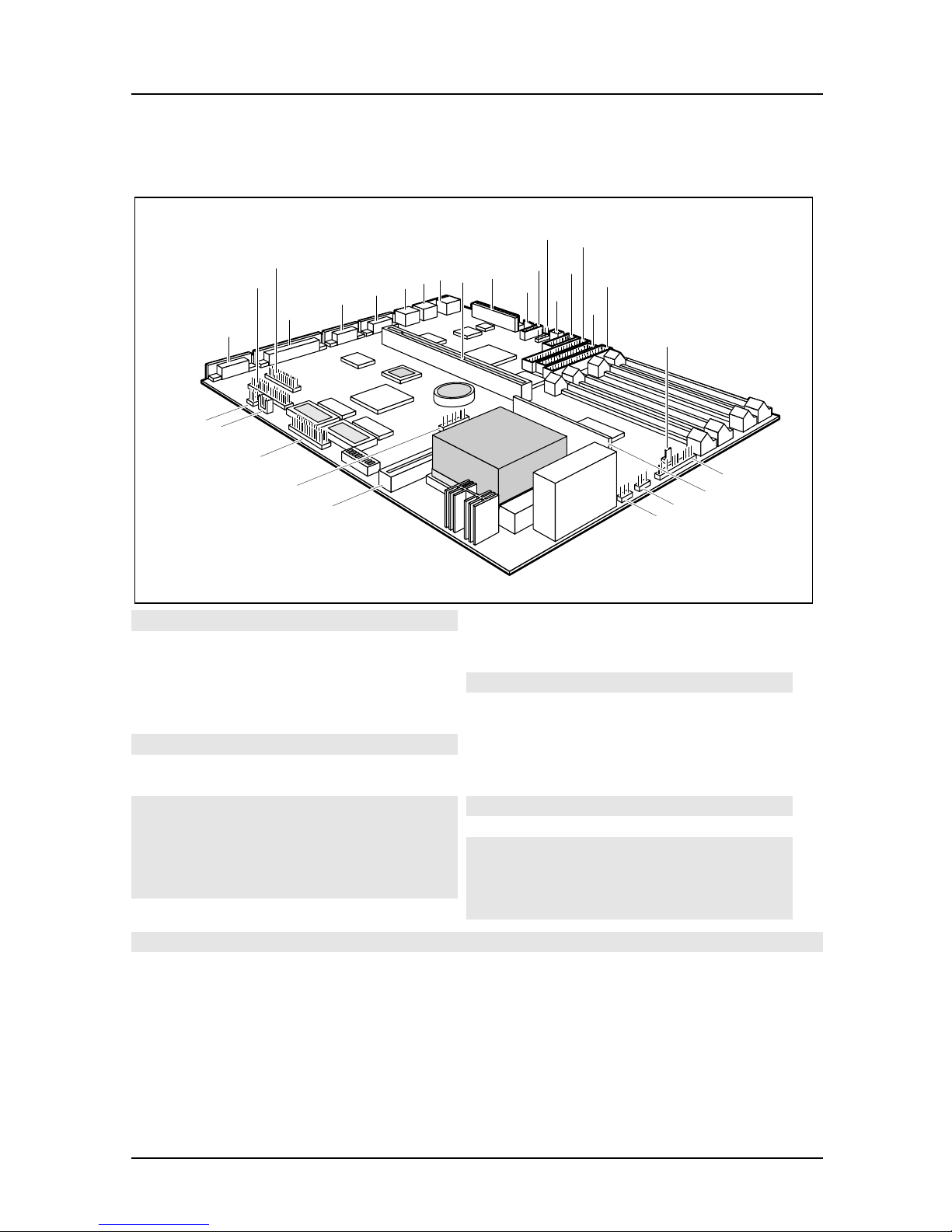
Interfaces and connectors
12
15
27
26
29
28
2
1
4
3
7
8
6
5
11
10
14
17
13
16
18
9
25
24
23
1 = Monitor port
2 = Parallel port
3 = Serial port 2
4 = Serial port 1
5= PS/2mouseport
6= PS/2keyboardport
7= USB
8= Slotboard
9 = Power supply
10 = Connector for soft-off power supply
11 = CD audio (input)
12 = infrared interface
13 = Remote on via fax/modem
14 = Chipcard reader
19
20
21
22
15 = IDE drives 1 and 2 (primary)
16 = Floppy disk drive
17 = IDE drives 3 and 4 (secondary)
18 = Power on switch
19 = LED indicators in front panel
20 = Voltage converter
21 = External loudspeaker
22 = Fan
23 = Cache board (second-level)
24 = LED indicators in front panel
25 = Feature board
26 = AUX IN
27 = Voice modem
28 = Game/Midi/Audio
29 = Wavetable board
The connectors marked do not have to be present on the system board.
4 A26361-D943-Z120-14-7619
Page 13

Possible screen resolution Introduction
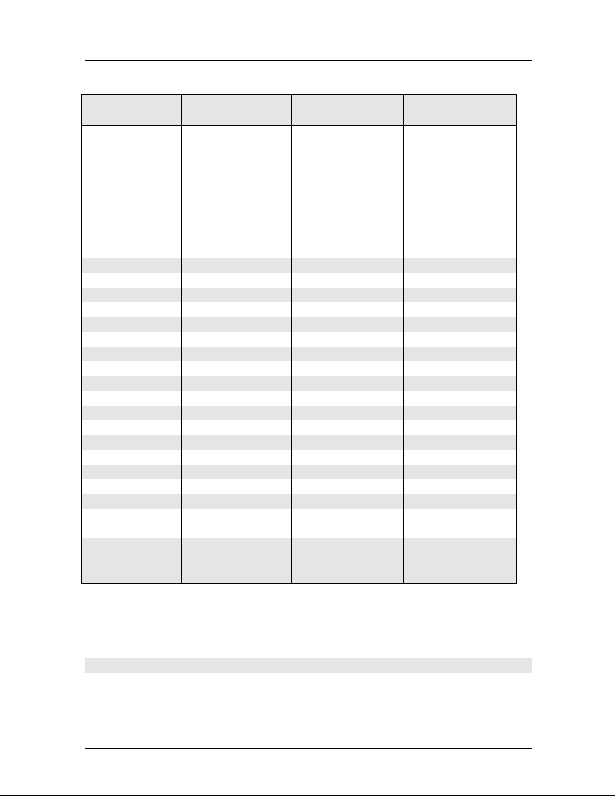
Possible screen resolution
Depending on the operating system used the screen resolutions in the following
table refer to the screen controller on the system board. If you are using an external
screen controller, you will find details of supported screen resolutions in the
Operating Manual or Technical Manual supplied with the controller.
You can set the screen resolution under Windows 95 by selecting
Display - Settings.
You can set the screen resolution under MS-DOS using the
SET-VGA program.
Control Panel -
A26361-D943-Z120-14-7619 5
Page 14
Introduction Possible screen resolution
Screen
resolution
Refresh rate (Hz) Horizontal-
rate (kHz) **
Max. number of
colors
640x350 70 31,5 16
640x350 84 38 16
640x480 60 31,5 16777216
640x480 75 37,5 16777216
640x480 85 43,4 16777216
640x480 100 50,6 16777216
720x400 70 31,5 16
720x400 84 38 16
800x600 60 38 65536
800x600 60 38 16777216
800x600 72 48 65536
800x600 72 48 16777216
800x600 75 47 65536
800x600 75 47 16777216
800x600 85 53,7 65536
800x600 85 53,7 16777216
800x600 100 63 65536
800x600 100 63 16777216
1024x768 87 interlaced 36 256
1024x768 87 interlaced 36 65536
1024x768 60 48,4 256
1024x768 60 48,4 65536
1024x768 75 60 256
1024x768 75 60 65536
1024x768 85 68,7 256 *
1024x768 85 68,7 65536 *
1024x768 100 81 256 *
1280x1024 87 interlaced 49 16
1280x1024 87 interlaced 49 256
1280x1024 60 63,7 256 *
1280x1024 75 80,4 256 *
* no 16 color mode
**
** The horizontal rate values may have a tolerance range of ± 0.3 kHz.
*** not for graphics processor Cirrus Logic CL-GD5446
The values marked are only available with a 2-Mbytes video memory.
6 A26361-D943-Z120-14-7619
Page 15

Resource table Introduction
Resource table
possible IRQ Possible
Address
Keyboard IRQ1
Serial port COM2 / IrDA IRQ3,
IRQ4
Serial interface COM1 / Chip card
reader
Floppydisk drive controller IRQ6 DMA2
Parallel interface LPT1 IRQ5, IRQ7 0278, 0378 DMA1, DMA3
RTC IRQ8
Audio controller
Joystick:
Base address:
MPU 401:
IRQ4,
IRQ3
IRQ5, IRQ7, IRQ9,
IRQ10
02F8, 03F8
02E8, 03E8
03F8, 02F8
03E8, 02E8
0200-0207
0220-022F
0240-024F
0260-026F
0280-028F
Possible
DMA
DMA1, DMA3,
DMA5, DMA7
0300-0301
0330-0331
Adlib:
USB controller IRQ11
Mouse controller IRQ12
Numeric processor IRQ13
IDE controller 1 IRQ14
IDE controller 2 IRQ15
The interrupts, addresses and DMAs set in the factoryare underlined.
„Possible IRQ“= these interrupts can be used for your particular application
„Possible address“= this address can be used for your particular application
„Possible DMA“ = this DMA can be used for your particular application
0338-038B
Please note that a resource cannot be used bytwo applications at the same
i
time.
A26361-D943-Z120-14-7619 7
Page 16

Page 17
Important notes
p
p
p
p
p
p
y
p
g
g
p
g
p
g
t
g
p
m
Store this manual close to the device. If you pass on the device to third parties, you
should also pass on this manual.
Be sure to read thispage carefullyand note the information beforeyou
!
o
en the PC.
Please note the information
O
eratingManual of the PC.
Incorrect re
ex
losion. It is therefore essential to observe the instructions in the
cha
ter „Add-on modules“-„Replacingthe lithium battery“.
The lithium batterymust be replaced with an identical batteryor a batter
type recommended bythe manufacturer (CR2032).
Do not throw lithium batteries into the trashcan. It must be dis
accordance with local re
This board complies with the requirements of the EEC directive
89/336/EEC with re
Com
When installin
information in the O
receivin
lacement of the lithium batterymaylead to a risk of
liance was tested in a typical PC configuration.
the board, refer to the specific installation
device.
rovided in the chapter "Safety"inthe
osed of in
ulations concerningspecial waste.
ard to "Electromagnetic compatibility".
eratingManual or Technical Manual of the
Data cables to peripheral devices must be adequately shielded.
Modules can become veryhot duringoperation. Make sureyou do no
!
i
touch modules when addingcomponents to the system board. There is a
dan
er of burns!
The warrantyexpires if the device is damaged duringthe installation or
re
lacement of system expansions. Information on which syste
expansionsyou can use is available fromyour sales office or the customer
service.
A26361-D943-Z120-14-7619 9
Page 18

Important notes
Boards with electrostatic sensitive devices (ESD) may be identified by labels.
When you handle boards fitted with ESDs, you must observe the following points
under all circumstances:
• You must always discharge yourself (e.g. by touching a grounded object)
before working.
• Theequipmentandtoolsyouusemustbefreeofstaticcharges.
• Pull out the power plug before inserting or pulling out boards containing
ESDs.
• Always hold boards with ESDs by their edges.
• Never touch pins or conductors on boards fitted with ESDs.
10 A26361-D943-Z120-14-7619
Page 19

Settings in BIOS Setup
gop
y
The BIOS Setup menu allows you to set your hardware configuration and system
functions. In addition, the BIOS Setup displays technical information on the PC's
configuration.
When it is supplied, the PC is set to factory default settings which you can alter in
the
BIOS Setup menus. You can change these settings in BIOS Setup. Any changes
you make take effect as soon as you save the settings and quit the
The Operating Manual describes how to call the
BIOS Setup and change menu
entries.
You can select the following settings in the
Main - system functions
Advanced - advanced system configuration
Security - security features
Power - power-management features
BIOSFaX - quick start functions
Exit -saveandquit
BIOS Setup:
The various menus are described below with all settingoptions. Since the
i
settin
them ma
tions depend onyour P C's hardware configuration, some of
not be offered in the BIOS setup.
BIOS Setup.
Main menu
In the Main menu you can set up the following:
• Time (in the field marked
• Date (in the field marked
• Floppy disk drive (in the field marked
• Hard disk drive (in the submenus of
• Display device (in the field marked
• System boot (in the submenus of
System Time)
System Date)
Diskette A or Diskette B)
Hard Disk)
Video Display)
Boot Options)
A26361-D943-Z120-14-7619 11
Page 20

Settings in BIOS Setup Main - system functions
M
y
g
Phoenix BIOS Setup
ain Advanced Security Power BIOSFaX Exit
System Time: [07:42:19]
System Date: [08/11/1995]
Diskette A: [1.4M]
Diskette B: [None]
Ê Hard Disk 1: 1 Gbyte
Ê Hard Disk 2: None
Ê Hard Disk 3: None
Ê Hard Disk 4: None
Ê Boot Options
Video Display: [EGA/VGA]
Base Memory: 640K
Extended Memory: 7M
F1 Help ↑↓ Select Item -/+ Change Values F9 Setup Defaults
ESC Exit
Example for Main menu
← → Select Menu Enter Execute Command F7 Previous Values
Item Specific Help
——————————————————————
System Time / System Date
The System Time field and the System Date field show the time and date respectively
according to the PC. The time is shown in the format hh:mm:ss
(hours:minutes:seconds) and the date is shown in the format mm/dd/yyyy
(month/day/year).
If the settingsintheSystem Time and System Date fields are frequentl
!
wrongwhenyoupower upthe computer, the lithium batteryis dead.
Chan
e the batteryas described in „Add-on modules“-„Replacingthe
lithium battery“).
Diskette A / Diskette B
These two fields are used to specify the type of floppy disk drive installed.
360K, 720K, 1.2M, 1.4M, 2.8M
The entry depends on the floppy disk drive installed.
(Default entry Diskette A :
(Default entry Diskette A :
None A floppy disk drive is not installed.
(Default entry for Diskette B:).
12 A26361-D943-Z120-14-7619
1.4M).
1.4M).
Page 21
Main - system functions Settings in BIOS Setup
y
d
g
M
HardDisk1toHardDisk4-Harddiskdrives
call the submenu to make corresponding settings of the IDE hard disk drive.
You should change the default settingsonlyifyou are connectingan
i
additional IDE drive to one of the two IDE connectors.
The maximum transfer rate of two IDE drives connected to the same
connector is determined b
therefore be connected to the first IDE connector and identified as
Disk 1 or Hard Disk 2. Slower hard disks or other IDE drives (e.
the slowest one. Fast hard disks should
Har
.CD
ROM drives) should be connected to the second IDE connector and
identified as
Hard Disk 3 or Hard Disk 4.
The following description of the setting options for
Disk 2
, Hard Disk 3 and Hard Disk 4. The default settings depend on the installed
Hard Disk 1 also applies to Hard
drive.
Phoenix BIOS Setup
ain
Hard Disk 1: 1 Gbyte Item Specific Help
Autotype Hard Disk: [Press Enter]
Type: [User]
Cylinders: [ 1654]
Heads: [ 16]
Sectors/Track: [ 63]
Write Precomp: [None]
Transfer Mode: [Standard]
LBA Translation: [Enabled]
PIO Mode: [Fast PIO 3]
32 Bit I/O: [Enabled]
F1 Help ↑↓ Select Item -/+ Change Values F9 Setup Defaults
ESC Exit
Example for the submenu Hard Disk
← → Select Menu Enter Execute Command F7 Previous Values
A26361-D943-Z120-14-7619 13
Page 22
Settings in BIOS Setup Main - system functions
y
y
k
y
p
p
Autotype Hard Disk
Onlyifyou have installed a new unrecorded IDE hard disk drive,you
!
should mark the
If
ou have set the hard diskparameters with Autotype Hard Disk,you can
onl
reduce the values.
Autotype Hard Disk field.
If you have installed a new unrecorded IDE hard disk drive, you should mark the
Autotype Hard Disk field and press Enter. This has the effect of setting the optimum
values for the IDE hard disk drive. You can change these values if you set the
Type
field to User.
Type - Hard Disk Type
Thisfieldisusedtospecifythetypeofharddiskdrive.
None You cannot change the hard disk parameters (Cylinders, Heads,
Sector/Track
and Write Precomp). An IDE drive has not been
installed.
1 to 39 The hard disk parameters (Cylinders, Heads, etc.) are preset.
Auto If the hard disk supports this mode, the setup menu reads the hard
disk parameters from the disk itself. You do not need to select the
parameters yourself.
User You can enter the hard disk parameters (Cylinders, Heads etc.)
yourself.
If you have set the hard disk parameters with
Autotype Hard Disk,
you can only reduce the values.
Examples of user-defined entries (IDE drives):
Hard dis
hard disk capacit
arameter 850 Mbyte 1,2 Gbyte 1,6 Gbyte
Cylinders 1654 2484 3148
Heads 16 1 6 16
Sectors 63 63 63
Write Precom
None None None
CD If an ATAPI CD-ROM drive is installed, this entry enables you to
boot from the CD-ROM drive.
14 A26361-D943-Z120-14-7619
Page 23

Main - system functions Settings in BIOS Setup
p
y
Cylinders, Heads, Sectors/Track, Write Precomp - hard disk parameter
These hard disk parameters are set in accordance with the IDE hard disk drive. If
you want to change the hard disk parameters manually, set the
Type field to User.
Transfer Mode
This field specifies the transfer mode for the IDE hard disk drive.
Standard One block is transferred for each interrupt (default entry).
2 Sectors, 4 Sectors, 6 Sectors, 8 Sectors, 16 Sectors
The set number of blocks (sectors) is transferred for each interrupt.
LBA Translation - Addressing
This field enables and disables the LBA (Logical Block Addressing) mode. LBA
mode allows you to install and use IDE hard disks with a capacity of more than
528 Mbytes. If a hard disk supports LBA mode, you can use the full capacity of
the IDE hard disk.
The default entry depends on the installed IDE hard disk drive. Change the default
entries only if you are installing another hard disk drive.
You mayonlyuse IDE drives in the LBA mode selected when theywere
!
set u
. In other words, ifyou set upa hard disk with LBA mode disabled,
ou mayonlyoperate the hard disk with LBA mode disabled.
Enabled If the hard disk supports LBA and it has a capacity of more than
528 Mbytes, the BIOS translates the hard disk parameters,
allowing the disk's full capacity to be used. This allows the disk's
full capacity to be used.
If the hard disk does not support LBA, its parameters are not
translated.
Disabled The BIOS uses the hard disk parameters and supports a maximum
capacity of 528 Mbytes.
A26361-D943-Z120-14-7619 15
Page 24

Settings in BIOS Setup Main - system functions
M
PIO Mode - Transfer rate
The PIO (Programmed Input Output) Mode defines the transfer rate of the IDE
hard disk drive.
Standard 0,8 Mbyte/s to 2 Mbytes/s (default entry)
Fast PIO 1 2Mbytes/sto4Mbytes/s
Fast PIO 2 4Mbytes/sto5Mbytes/s
Fast PIO 3 5Mbytes/sto10Mbytes/s
Fast PIO 4 more than 10 Mbyte/s
32 Bit I/O - Bus width for data transfer
This field specifies the width of data transmission between the processor and the
IDE controller.
Enabled The data transfer is 32 bits in width at the PCI bus. This enhances
performance (default entry).
Disabled The data transfer is 16 bits in width.
Boot Options
calls the submenu in which you can select the settings for system startup of the PC.
Phoenix BIOS Setup
ain
Boot Options Item Specific Help
POST Error Halt: [Halt On All Errors]
Quick Boot: [Disabled]
Quiet Boot: [Disabled]
Boot Sequence: 1. Diskette
F1 Help ↑↓ Select Item -/+ Change Values F9 Setup Defaults
ESC Exit
Example for submenu Boot Options
← → Select Menu Enter Execute Command F7 Previous Values
2. Hard Disk
3. CD ROM
16 A26361-D943-Z120-14-7619
Page 25

Main - system functions Settings in BIOS Setup
POST Error Halt - Aborting system startup
defines whether the system startup is to be aborted and the system halted when an
error is detected.
Halt On All Errors
If the self-test detects an error, system startup is aborted after the
self-test, and the system is halted (default entry).
No Halt On Any Errors
The system startup is not aborted. The error is ignored as far as
possible. The error is ignored as far as possible.
Quick Boot
can reduce the extent of the self-test and thus accelerate the system startup.
Enabled When the PC is switched on, the quick self-test is carried out, in
which the floppy disk drives are not checked.
Disabled When the PC is switched on, the complete PC configuration is
tested (default entry).
Quiet Boot
Instead of a start information a logo is displayed on the screen.
Enabled The logo is displayed on the screen. A switch to the start
information is made if you press the
Disabled The start information is displayed on the screen (default entry).
[Esc]
[Esc] key or if errors occur.
[Esc][Esc]
A26361-D943-Z120-14-7619 17
Page 26

Settings in BIOS Setup Main - system functions
Boot Sequence
defines the sequence in which the system BIOS searches the drives for system files
to start the operating system. If you wish to change this sequence, place the cursor
on the entry for the drive you to which wish to move forward (
[+]
[+] key) or back ([-]
[+][+]
[-]
[-][-]
key).
Default entry:
1. 1. Diskette
2. Hard Disk
3. CD ROM
Video Display
This field is used to specify the type of monitor connected.
EGA/VGA, Color 80, Monochrome
Default entry: EGA/VGA
Base Memory
This field indicates the size of the available base memory below 1 Mbyte.
Extended Memory
indicates the size of the memory above 1 Mbyte.
18 A26361-D943-Z120-14-7619
Page 27

Advanced - advanced system configuration Settings in BIOS Setup
t
A
Advanced menu - Making advanced system settings
Change the default settingsonlyfor special applications. Incorrec
!
settings can cause malfunctions.
You can make the following system settings in the
• Internal cache and second-level cache (in the
• Copy BIOS sections to the RAM (in the
• Interfaces and controllers (in the
• PCI functionality (in the
• System settings (in the
PCI Configuration submenu)
Advanced System Configuration submenu)
• Plug&Play functionality (in the
• Configuration data (in the
• Hard disk access (in the
Phoenix BIOS Setup
Main
Setting items on this menu to incorrect
values
may cause your system to malfunction.
Ê Cache Memory
Ê Shadow Memory
Ê Peripheral Configuration
Ê PCI Configuration
Ê Advanced System Configuration
Plug & Play O/S: [Yes]
Reset Configuration Data: [No]
dvanced Security Power BIOSFaX Exit
Warning!
Reset Configuration Data field)
Large Disk Access Mode field)
Peripheral Configuration submenu)
Plug and Play O/S field)
Shadow Memory submenu)
Advanced menu:
Cache Memory submenu)
Item Specific Help
——————————————————————
Large Disk Access Mode: [DOS]
F1 Help ↑↓ Select Item -/+ Change Values F9 Setup Defaults
ESC Exit
Example for the Advancedmenu
A26361-D943-Z120-14-7619 19
← → Select Menu Enter Execute Command F7 Previous Values
Page 28

Settings in BIOS Setup Advanced - advanced system configuration
A
Cache Memory
calls the submenu in which you can make the settings for the internal cache (in the
processor) and the second-level cache (on the system board).
Phoenix BIOS Setup
dvanced
Cache Memory Item Specific Help
Cache: [Intern And Extern]
Cache Mode: Write Back
Cache System BIOS Area: [Enabled]
Cache Video BIOS Area: [Enabled]
Cache Memory Regions:
C800 - CBFF: [Disabled]
CC00 - CFFF: [Disabled]
D000 - D3FF: [Disabled]
D400 - D7FF: [Disabled]
D800 - DBFF: [Disabled]
DC00 - DFFF: [Disabled]
F1 Help ↑↓ Select Item -/+ Change Values F9 Setup Defaults
ESC Exit
Example for submenu Cache Memory
← → Select Menu Enter Execute Command F7 Previous Values
Cache - cache utilization
This field switches the cache on and off. The cache is a buffer to which parts o f the
main memory and BIOS can be temporarily copied. The PC's performance is
higher when the cache is switched on.
You must disable the cache, if the access time is too short for older applications.
Intern Only Only the internal cache is used.
Intern And Extern
Internal (first-level cache) and external cache (second-level cache)
are enabled. I f there is no external Cache, only the internal cache is
used.
Disabled Internal (first-level cache) and external cache (second-level cache)
are disabled. All cache-related settings are then without effect.
20 A26361-D943-Z120-14-7619
Page 29

Advanced - advanced system configuration Settings in BIOS Setup
y
CacheMode-TransferMode
Requirement: The
Cache Mode sets the mode in which the CPU uses the cache. The field is set to Write
and can not be changed
Back
Cache field must be set to Intern Only or Intern And Extern.
In write-back mode the processor writes information to the cache and the
information is only written to the main memory if necessary. The information is
only written to the main memory if necessary. Main memory and cache contents
are not identical.
Cache System BIOS Area / Cache Video BIOS Area
TheCachefieldmustbesetto
Cache System BIOS Area and Cache Video BIOS Area lets you specify the BIOS that
Intern only or Intern and Extern.
should be mapped to the cache. Mapping the BIOS to the cache increases system
performance.
Enabled The specified BIOS is mapped to the cache (default entry).
Disabled The specified BIOS is not mapped to the cache.
Cache Memory Regions
TheCachefieldmustbesetto
Cache Memory Regions lets you specify the BIOS ROM areas that should be mapped
Intern only or Intern and Extern.
to the cache. Mapping the BIOS ROM areas to the cache increases system
performance.
Enabled The relevant ROM area is mapped to the cache.
Disabled The relevant ROM area is not mapped to the cache (default entry).
Ifyour ISA board uses a dualported RAM in the associated ROM area,
!
set the entr
to Disabled.
A26361-D943-Z120-14-7619 21
Page 30

Settings in BIOS Setup Advanced - advanced system configuration
A
Shadow Memory
calls the submenu in which you can specify which parts of the ROM (Read Only
Memory) are to be copied to the faster RAM (Random Access Memory) at system
startup.
Phoenix BIOS Setup
dvanced
Shadow Memory Item Specific Help
System Shadow: Enabled
Video Shadow: [Enabled]
Shadow Memory Regions:
C800 - CBFF: [Disabled]
CC00 - CFFF: [Disabled]
D000 - D3FF: [Disabled]
D400 - D7FF: [Disabled]
D800 - DBFF: [Disabled]
DC00 - DFFF: [Disabled]
F1 Help ↑↓ Select Item -/+ Change Values F9 Setup Defaults
ESC Exit
Example for submenu Shadow Memory
← → Select Menu Enter Execute Command F7 Previous Values
System Shadow
This field is always
Enabled, because the System BIOS is automatically copied to
the faster RAM.
Video Shadow
This field allows you to copy the video BIOS to fast RAM. Copying the video
BIOS to fast RAM increases system performance.
Enabled The video BIOS is copied to fast RAM (default entry).
Disabled The video BIOS is not copied to fast RAM. This setting is not
effective with an external screen controller connected to the PCI
bus.
22 A26361-D943-Z120-14-7619
Page 31

Advanced - advanced system configuration Settings in BIOS Setup
y
A
Shadow Memory Regions - ROM areas
Shadow Memory Regions allows you to copy ROM areas to fast RAM. Copying
ROM areas to fast RAM increases system performance.
Enabled The ROM area is copied to fast RAM.
Disabled The ROM area is not copied to fast RAM (default entry).
Ifyour ISA board uses a dualported RAM in the associated ROM area,
!
set the entr
to Disabled.
Peripheral Configuration - Ports and Controllers
calls the submenu in which you can set the interfaces and controllers.
Phoenix BIOS Setup
dvanced
Peripheral Configuration Item Specific Help
Serial 1: [Auto]
Serial 2: [Auto]
Serial 2 Mode: [Standard]
Parallel: [Auto]
Parallel Mode: [Printer]
Diskette Controller: [Enabled]
Hard Disk Controller: [Primary And
Secondary]
Mouse Controller: [Enabled]
Audio Controller: [Enabled]
USB Controller: [Disabled]
F1 Help ↑↓ Select Item -/+ Change Values F9 Setup Defaults
ESC Exit
Example for submenu Peripheral Configuration
← → Select Menu Enter Execute Command F7 Previous Values
A26361-D943-Z120-14-7619 23
Page 32

Settings in BIOS Setup Advanced - advanced system configuration
Serial 1 / Serial 2 - Serial interfaces
This field selects the address and the interrupt used to access the relevant serial
interface.
3F8h, IRQ4, 2F8h, IRQ3, 3E8h, IRQ4, 2E8h, IRQ3,
The serial port is set to the shown address and interrupt.
Auto The serial interface is automatically set to the next available
combination (address, interrupt) (Default entry).
Disabled The serial interface is disabled.
Serial 2 Mode - Serial interfaces
This field defines whether the second serial port is used as the standard port or as
the infrared interface.
If you wish to use infrared data transfer, an infrared interface with the associated
hardware must be incorporated in the device.
Standard The port operates as a serial port (default). Standard
IRDA (Infra-Red Data Association) The serial port permits infrared data
transfer up to 115 kbit/s. External serial port 2 does not function.
Parallel - parallel interface
This field selects the address and the interrupt used to access the parallel interface.
378h, IRQ7, 278h, IRQ5, 3BCh, IRQ7
The parallel port is set to the shown address and interrupt.
Auto The parallel interface is automatically set to the next available
combination (address, interrupt) (Default entry).
Disabled The parallel interface is disabled.
24 A26361-D943-Z120-14-7619
Page 33

Advanced - advanced system configuration Settings in BIOS Setup
Parallel Mode
This field is used to specify whether the parallel interface is to be used as a bidirectional input/output port or just as an output port.
ECP and EPP transfer modes
allow faster transfer rates of 2 and 2.4 Mbytes/s. These modes will only work with
peripheral devices which support them. In addition, the field Parallel must be set to
378h or 278h.
Printer The port functions as an output port only (default entry).
Bidirection Data can be transferred in both directions across the port.
EPP Fast transfer mode (up to 2 Mbytes/s), can output and receive data.
The mode requires a peripheral device which supports the EPP
(Enhanced Parallel Port) transfer mode.
ECP Fast transfer mode (up to 2.4 Mbytes/s), can output and receive
data. The mode requires a peripheral device which supports the
EcP (Enhanced Capability Port) transfer mode. The DMA channel
required is determined by the system in accordance with Plug &
Play.
Diskette Controller
This field is used to enable and disable the built-in floppy disk controller on the
system board.
Enabled The floppy disk controller is enabled - IRQ 6 is used. (default
entry).
Disabled The floppy disk controller is disabled - IRQ 6 is free.
Hard Disk Controller
This field allows you to enable and disable the built-in IDE hard disk controller.
The associated interrupts (IRQ 14 for the first connector, IRQ 15 for the second
connector) will only be available if no IDE hard disk drive is physically connected.
A26361-D943-Z120-14-7619 25
Page 34

Settings in BIOS Setup Advanced - advanced system configuration
Primary The first IDE hard disk controller is enabled (default entry). Two
IDE drives ( preferably high-speed hard disks) can be attached to
the first (primary) connector. IRQ14 is occupied.
Primary And Secondary
Primary and secondary IDE drive controllers are activated (default
entry). Up to four IDE drives can be connected. Low-speed drives
are preferred for the second (secondary) connector (e.g. CDROM). IRQ14 and IRQ15 are occupied.
Disabled The two IDE hard disk controller are disabled.
Mouse Controller
This field is used to enable and disable the built-in mouse controller on the system
board.
Enabled The mouse controller is enabled (default entry)- IRQ 12 is used. .
Disabled The mouse controller is disabled - IRQ 12 is free.
Audio Controller
This field sets the base address for the audio controller on the system board or
disables the audio controller.
Enabled The system BIOS determines which system resources (interrupts,
addresses, DMAs) are occupied (default entry).
Disabled The audio controller is disabled.
USB Controller
switches the USB controller (Universal Serial Bus) of the system board on or off.
Enabled The system BIOS determines which system resources (interrupts,
addresses) are occupied.
Disabled The USB controller is disabled (default entry).
26 A26361-D943-Z120-14-7619
Page 35

Advanced - advanced system configuration Settings in BIOS Setup
A
PCI Configuration
calls the submenu in which you can make the settings for the PCI slots.
Phoenix BIOS Setup
dvanced
PCI Configuration Item Specific Help
PCI Interrupt Mapping INTA#: [Auto]
PCI Interrupt Mapping INTB#: [Auto]
PCI Interrupt Mapping INTC#: [Auto]
PCI Interrupt Mapping INTD#: [Auto]
VGA Interrupt: [Disabled]
PCI Device, Slot #1
Default Latency Timer: [Yes]
Latency Timer: [0040]
PCI Device, Slot #2
Default Latency Timer: [Yes]
Latency Timer: [0040]
PCI Device, Slot #3
Default Latency Timer: [Yes]
Latency Timer: [0040]
F1 Help ↑↓ Select Item -/+ Change Values F9 Setup Defaults
ESC Exit
← → Select Menu Enter Execute Command F7 Previous Values
Example for submenu PCI Configuration
A26361-D943-Z120-14-7619 27
Page 36

Settings in BIOS Setup Advanced - advanced system configuration
PCI Interrupt Mapping INTx# - Assignment of the PCI interrupts
defines which PCI interrupt is switched to which ISA interrupt. For the change to
take effect, you must switch your PC off and then on again after the Setup BIOS
has terminated.
A multifunctional PCI board can use all PCI interrupts, if need be.
If you use a setting other than
Auto, the Plug&Play functionality of the system
BIOS for PCI boards is deactivated.
The PCI interrupts INTA#, INTB#and INTC# are assigned as follows:
PCI slot 1 = INTA#, PCI slot 2 = INT B#, PCI slot 3 = INTC#
Auto The PCI interrupts are assigned automatically in accordance with
the Plug&Play guidelines (default entry).
Disabled No PCI interrupt is used for the PCI board in the assigned PCI
slot.
IRQ03, IRQ04, IRQ05, IRQ06, IRQ07, IRQ09, IRQ10, IRQ11, IRQ12, IRQ14, IRQ15
The PCI interrupt is switched to the selected ISA interrupt. You
may not select an ISA interrupt that is used by a component on the
system board (e.g. controller) or an ISA board.
VGA Interrupt - Assigning PCI-VGA interrupt
assigns PCI interrupt to the screen controller on the built-in PCI board. If you have
not defined any other interrupt with
Enabled The interrupt is assigned to the screen controller on the built-in
PCI Interrupt Mapping, IRQ9 is assigned.
PCI board (default entry).
Disabled The interrupt can be used for other add-on boards.
28 A26361-D943-Z120-14-7619
Page 37

Advanced - advanced system configuration Settings in BIOS Setup
A
PCI Device, Slot #n: Default Latency Timer
specifies the lowest number of clock cycles in which a PCI master board can be
active at the PCI bus;
n stands for the number of the PCI slot. For the change to
take effect, you must switch your PC off and then on again after the Setup BIOS
has terminated.
Yes The value predefined by the PCI board is accepted. The entry in
the corresponding field for PCI Device, Slot #n:
Latency Timer is
ignored
No The value predefined by the PCI board is ignored. The value set in
the relevant field of
PCI Device, Slot #n: Latency Timer determines
the number of clock cycles.
PCI Device, Slot #n: Latency Timer
Requirement: The relevant field of
be set to
No.
PCI Device, Slot #n: Default Latency Timer must
The field defines the lowest number of clock cycles in which a burst can be
transferred on the PCI bus.
0000h to 0280h Number of clock cycles (default entry = 0040h).
n stands for the number of the PCI slot.
Advanced System Configuration
calls the submenu in which you can make additional settings.
Phoenix BIOS Setup
dvanced
Advanced System Configuration Item Specific Help
ISA Memory Gap: [Disabled]
Parity Mode: [Disabled]
Memory Performance: [Fast]
Cache Performance: [Fast]
Memory Current: [8mA]
Feature Connector: [Disabled]
F1 Help ↑↓ Select Item -/+ Change Values F9 Setup Defaults
ESC Exit
Example for submenu Advanced System Configuration
← → Select Menu Enter Execute Command F7 Previous Values
A26361-D943-Z120-14-7619 29
Page 38

Settings in BIOS Setup Advanced - advanced system configuration
ISA Memory Gap
inserts a contiguous ISA memory area of 1 Mbyte into the main memory area of 15
to 16 Mbytes.
Enabled The ISA memory area is inserted.
Disabled The ISA memory area is not inserted (default).
Parity Mode - DRAM Parity Check
Determines whether a parity check is carried out in the case of DRAM modules. If
the system BIOS detects that at least one DRAM module does not have a parity
bit, the parity check is generally disabled.
Disabled No parity check is performed.
Parity The parity check is set in parity mode. A bit corruption is recognized
and an error message is issued (default entry).
ECC A bit corruption is corrected (no error message). An error message is
issued for two or more bit corruptions.
Memory Performance
determines whether greater tolerances should be permitted for memory timing.
Standard Memory timing is programmed for EDO memory modules which
takes account of all possible tolerances.
Fast Setting performance of system.
Cache Performance
determines whether greater tolerances should be permitted for cache timing.
Standard Greater tolerances are permitted for cache timing.
Fast Setting performance of system.
Memory Current
defines the memory current to be supplied to the memory modules.
8mA The memorymodules are supplied with 8mA memory current.
12mA The memory modules are supplied with 12mA memory current.
The 12mA setting is only necessary if you are using memory
modules with a large storage capacity (upwards of 64 Mbyte),
which have a large number of memory chips.
Feature Connector - Enabling of Feature Connectors
This field is used to enable and disable the feature connector on the system board.
Enabled The feature connector is enabled.
Disabled The feature connector is disabled (default entry).
30 A26361-D943-Z120-14-7619
Page 39

Advanced - advanced system configuration Settings in BIOS Setup
Plug & Play O/S
defines the Plug&Play functionality. Plug&Play means that inserted modules are
automatically recognized and installed if they support Plug&Play.
Yes The operating system takes over some of the Plug&Play functions.
You should select this setting only if the operating system supports
Plug&Play.
No The BIOS takes over the c omplete Plug&Play functionality
(default setting).
A26361-D943-Z120-14-7619 31
Page 40

Settings in BIOS Setup Advanced - advanced system configuration
Reset Configuration Data
This field specifies whether the configuration data is reset and reinitialized when
the PC is started.
Yes When the PC is started the old configuration data is reset and the
entry in this field is set to NO. The new configuration data is
determined by means of the Plug&Play functionality. The mounted
modules and drives are then initialized with this data.
No The Plug&Play functionality ascertains the current configuration
data and uses it to initialize the installed modules and drives. There
is no update when the system is started (default entry).
Large Disk Access Mode - Hard disk access
specifies the type of hard disk access for large hard disks (more than 1024
cylinders, 16 heads). The default setting depends on the operating system used.
DOS the operating system uses MS-DOS-compatible hard disk accesses.
Other If the operating system uses hard disk accesses which are not MS-
DOS-compatible (e.g. Novell, SCO Unix).
32 A26361-D943-Z120-14-7619
Page 41

Security menu - Setting up the security features Settings in BIOS Setup
y
Menu Security - Setting up the security features
You can set up the following security features in the Security menu:
• Protecting BIOS Setup (in the field marked
• Protecting BIOS of add-on modules (in the field marked
• Protecting system boots (in the field marked
• Locking input devices (in the field marked
• Prevention of system boots from floppy disk (in the field marked
• Displaying Setup message (in the
• Virus Warning (in the field marked
Setup Prompt field)
Virus Warning)
• Prevention of write operations to floppy disk (in the field marked
)
Write
• Write protection of System BIOS (in the field marked
• On/Off functionality (in the submenu
Power On/Off)
Set Setup Password)
Setup Password Lock)
Set System Password)
System Password Mode)
System Load)
Diskette
Flash Write)
Phoenix BIOS Setup
Main Advanced
Setup Password Not Installed
System Password Not Installed
Set Setup Password: [Press Enter]
Setup Password Lock: [Standard]
Set System Password: [Press Enter]
System Password Mode: [System]
System Load: [Standard]
Setup Prompt: [Enabled]
Virus Warning: [Disabled]
Diskette Write: [Enabled]
Flash Write: [Enabled]
Ê Power On/Off
F1 Help ↑↓ Select Item -/+ Change Values F9 Setup Defaults
ESC Exit
Example for Security menu
← → Select Menu Enter Execute Command F7 Previous Values
Securit
Power BIOSFaX Exit
Item Specific Help
——————————————————————
Setup Password / System Password
These fields indicate whether the appropriate password is installed or not.
A26361-D943-Z120-14-7619 33
Page 42

Settings in BIOS Setup Security - security features
Set Setup Password
This field enables you to install the setup password. The setup password prevents
unauthorized callup of the
BIOS setup.
Mark the field and press the Return key. You can then enter and confirm the setup
password (see also the PC Operating Manual).
Setup Password Lock
specifies the effect of the Setup Password. The setting in this field takes effect as
soon as a Setup Password has been installed.
Standard The setup password prevents unauthorized callup of the BIOS setup
(Default entry).
Extended The Setup Password prevents unauthorized calls of the BIOS Setup
and locks the keyboard when the PC is initialized. This prevents
unauthorized access to settings for installed boards with a BIOS of
their own.
Set System Password
Requirement: The setup password is installed.
This field enables you to install the system password. The system password
prevents unauthorized access to your system.
Mark the field and press the Return key. You can then enter and confirm the
system password (see also the PC Operating Manual).
34 A26361-D943-Z120-14-7619
Page 43

Security menu - Setting up the security features Settings in BIOS Setup
System Password Mode
specifies the effect of the system password. The setting in this field becomes
effective as soon as a system password is installed.
System When the PC is started, the system password enables the operating
system to be booted.
Keyboard When the PC is started, the operating system is booted and the
keyboard and mouse are locked. The system password unlocks the
keyboard and mouse.
System Load
This field specifies the drive from which the operating system can be loaded.
Standard The operating system can be loaded from floppy disk or hard disk
(default entry).
Diskette Lock The operating system can only be loaded from hard disk.
Setup Prompt- Setup message
specifies whether the setup message Press F2 to enter SETUP is displayed
when the system is rebooted.
Enabled The setup message Press F2 to enter SETUP is displayed
when the system is started (default entry).
Disabled The setup message is not displayed.
A26361-D943-Z120-14-7619 35
Page 44

Settings in BIOS Setup Security - security features
Virus Warning
This field checks the boot sectors of the hard disk drive to see if any changes have
been made since the previous system startup. If they have been changed and the
reason for this is unknown, a program for finding computer viruses should be
loaded.
Enabled If the boot sector has been changed since the previous system
startup (e.g. new operating system or virus attack), a warning is
displayed. The warning stays on the screen until you acknowledge
the changes with Confirm or deactivate the function (Disabled).
Confirm This entry confirms a required change in a boot sector (e.g. new
operating system).
Disabled The boot sectors are not checked (default entry).
Diskette Write
This field is used to enable and disable floppy disk write-protection.
Enabled Floppy disks can be read, written or deleted, the write protection in
BIOS setup must be disabled (switch 8 off, default entry).
Disabled Floppy disks can only be read.
Flash Write
This field can assign write protection to the System BIOS.
Enabled The system BIOS can be written or deleted, if write protection for
the System BIOS is disabled in the BIOS setup (switch 5 =
BIOS update from floppy disk is possible (default entry).
Disabled The System BIOS can neither be written to nor deleted . BIOS
update from floppy disk is not possible
off).
36 A26361-D943-Z120-14-7619
Page 45

Security menu - Setting up the security features Settings in BIOS Setup
y
t
p
g
y
m
p
y
Power On/Off
calls the submenu in which you can specify how the system can be powered on and
off. These settings cause the to be switched on and off in the same way as using the
on/off button on the system unit. The on/off button is always operable and cannot
be disabled.
Securit
Power On/Off Item Specific Help
Power Off Source
Software: [Enabled]
Keyboard: [Enabled]
Power On Source
Remote: [Enabled]
Keyboard: [Enabled]
Timer: [Enabled]
Chipcard: [Enabled]
F1 Help ↑↓ Select Item -/+ Change Values F9 Setup Defaults
ESC Exit
Example for submenu Power On/Off
← → Select Menu Enter Select Ê Sub-Menu F7 Previous Values
Phoenix BIOS Setup
Ifyou have assigned a systempassword in System Mode, the boo
!
rocedure is suspended duringremotepower on of the system (usin
Remote Power On or Timer On)asthes
stem waits for entryof the syste
assword. For this reasonyou should not assignasystempassword in
System Mode if
ou want to use remotepower-on.
Power Off Source: Software
specifies whether the system can be switched off with a program (
or an operating system (
Enabled The system can be switched off with the SWOFF program (default
entry).
Disabled The system cannot be switched off with a program.
A26361-D943-Z120-14-7619 37
DeskOff, SWOFF)
Windows 95, Windows NT with Siemens Nixdorf HAL).
Page 46

Settings in BIOS Setup Security - security features
Power Off Source: Keyboard
specifies whether the system can be switched off using a special on/off button on
the keyboard.
Enabled The system can be switched off using a special on/off button on the
keyboard.
Disabled The system cannot be switched off using a special on/off button on
the keyboard (default).
Power On Source: Remote
specifies whether the system can be switched on by an incoming message (e. g.
modem). The signal can be supplied externally via serial interface 1 or internally
via the remote on connector.
Enabled The system can be switched on from an incoming message (default
entry).
Disabled The system cannot be switched on from an incoming message.
Power-on Source: Keyboard
specifies whether the system can be switched on using a special on/off button on
the keyboard.
Enabled The system can be switched on using a special on/off button on the
keyboard (default entry).
Disabled The system cannot be switched on using a special on/off button on
the keyboard.
38 A26361-D943-Z120-14-7619
Page 47

Security menu - Setting up the security features Settings in BIOS Setup
y
Power-on Source: Timer
specifies whether the system can be timed to switch on at a particular time or after
a particular period of time.
The switch-on time cannot be specified in BIOS Setup. You require a suitable
program for setting this switch-on time.
Enabled The system can be switched on at set times.
Disabled The system cannot be switched on under timer control (default
entry).
Rebootingafter a critical system error (ASR&R Boot Delay field in the
!
Server menu) is not affected b
this setting.
Chipcard
specifies whether the system can be switched on via the chipcard reader.
Enabled The system can be switched on via the chipcard reader (default).
(Default entry.)
Disabled The system cannot be switched on via the chipcard reader.
A26361-D943-Z120-14-7619 39
Page 48

Settings in BIOS Setup Power - power-management features
Power menu - Setting energy saving functions
Programs for power management (e.g. POWER.EXE) can change the settings for the
energy saving functions.
You can set the following functions in the
• Enabling of APM interface (in the
• Extent of energy saving functions (in the
• Standby mode (in the
• Suspend mode (in the
Standby Timeout field)
Suspend Timeout field)
• Hard disk energy saving functions (in the
• Processor speed in standby mode (in the
• Save system status (in the
Save To Disk field)
• Defining system activities (in the
Power menu:
Advanced Power Managementfield)
Power Management Mode field)
Hard Disk Timeout field)
Standby CPU Speed field)
Wakeup Event field)
Phoenix BIOS Setup
Main Advanced Security
APM [Enabled]
Power Management Mode: [Customize]
Standby Timeout: [15 min]
Suspend Timeout: [10 min]
Hard Disk Timeout: [10 min]
Standby CPU Speed: [Medium]
Save To Disk: [Disabled]
Ê Wakeup Event
F1 Help ↑↓ Select Item -/+ Change Values F9 Setup Defaults
ESC Exit
Example for menu Power
← → Select Menu Enter Execute Command F7 Previous Values
Power BIOSFaX Exit
Item Specific Help
——————————————————————
APM - Enabling the APM Interface
Determines whether an operation system can change the power management
settings in the system BIOS.
Enabled The operating system has access to the power management settings
and can change these if necessary (default entry).
Disabled Changes can not be made to power management setting by an
operating system.
40 A26361-D943-Z120-14-7619
Page 49

Power Settings in BIOS Setup
Power Management Mode - Extent of energy saving functions
This field defines the extent of the energy saving functions.
Customize The functions set in the fields Standby Timeout, Hard Disk Timeout
and Standby CPU Speed are effective in power management (default
entry). (Default entry).
Maximum, Medium or Minimum Power Savings
These entries call predefined settings, thus determining the extent
of energy saving.
Disabled None of the energy saving functions is effective.
Standby Timeout
Requirement: The Power Management Mode must be set to Customize.
This field defines the amount of time without system activity the PC is to wait
before switching to standby mode. In standby mode, the screen is dark and the
processor clock is set in accordance with the entry in the
The next wakeup event terminates standby mode again
2 min, 5 min, 10 min, 15 min, 30 min
Default entry = 15 min.
Standby CPU Speed field.
Disabled
The PC does not switch to standby mode.
Suspend Timeout - Suspend mode
Requirement: The Power Management Mode must be set to Customize.
This field defines the amount of time without system activity the system is to wait
before switching to standby mode. In standby mode, the screen is dark and the
processor is switched off.
The next wakeup event terminates suspend mode again.
In a network environment
will be aborted.
2 min, 15 min, 30 min, 1 Std, 2 Std, 3 Std, 4 Std
Default entry = 15 min.
Disabled The PC does not switch to suspend mode
Suspend Timeout must be disabled, otherwise data transfer
A26361-D943-Z120-14-7619 41
Page 50

Settings in BIOS Setup Power - power-management features
Hard Disk Timeout
Requirement: The Power Management Mode must be set to Customize.
This field defines the amount of time without system activity before the motor of
the hard d isk drive is switched off. As soon as there is a hard disk access, the
motor is switched back on.
2 min, 5 min, 10 min, 15 min
Default entry = 10 min.
Disabled
The PC does not switch off the hard disk drive.
Standby CPU Speed
Requirement: The Power Management Mode must be set to Customize.
This field specifies the processor's clock speed in standby mode. The entries
Medium and Low cause programs to run more slowly.
In a network environment the processor's clock speed must be set to
Max,
High,
otherwise data transfer will take place at reduced speed.
Max Maximum clock speed
High 1/4 of maximum clock speed
Medium 1/8 of maximum clock speed (default entry )
Low 1/16 of maximum clock speed
Save To Disk
Requirement: The Power Management Mode must be set to Customize.Theremustbe
sufficient storage space on the hard disk.
This field specifies whether the current system status (active programs, files,
memory contents) is saved to file
suspend mode. This system status is restored when you restart the system; in other
words, you can carry on working in the same application.
Enabled The contents of the main memory, working memory, video
memory and cache are saved to the hard disk.
SAVETO.DSK when the system switches to
Disabled The memory contents are not saved (default entry).
42 A26361-D943-Z120-14-7619
Page 51

Power Settings in BIOS Setup
g
grap
pplyify
g
g
The Enabled setting only works with:
• Controllers integrated on the system board (e. g. graphics and audio
controllers)
• Add-on boards indicated in the price list.
Other add-on boards are not supported at present.
Do not set the entryin the Save to Disk field to Enabled,ifyou are usin
!
boards other than those listed above. This applies, for example, to add-on
boards such as SCSI controllers and
These restrictions also a
to disk) under Windows usin
Before startin
documents located on network drives.
the Save to Disk function,you should first close all
ou activate the Quickstart function (Save
DeskEnergy.
hics controllers.
A26361-D943-Z120-14-7619 43
Page 52

Settings in BIOS Setup Power - power-management features
Wakeup E vent - Defining system activities
This field calls the submenu in which you can set the interrupts which are to be
evaluated as system activities. When one of these interrupts occurs, the active
energy saving mode is terminated, for example.
In a network environment the
must be disabled, otherwise the system will not switch to
Phoenix BIOS Setup
Power
Wakeup Event Item Specific Help
IRQ 1: Enabled
IRQ 3: [Disabled]
IRQ 4: [Disabled]
IRQ 5: [Disabled]
IRQ 6: [Enabled]
IRQ 7: [Disabled]
IRQ 8: [Disabled]
IRQ 9: [Disabled]
IRQ 10: [Disabled]
IRQ 11: [Disabled]
IRQ 12: [Enabled]
IRQ 13: Disabled
IRQ 14: [Enabled]
IRQ 15: [Enabled]
Wakeup Event for the network controller interrupt
Standby Mode.
F1 Help ↑↓ Select Item -/+ Change Values F9 Setup Defaults
ESC Exit
← → Select Menu Enter Select Ê Sub-Menu F7 Previous Values
Example for Wakeup Event submenu
Enabled The associated interrupt is evaluated as a system activity.
Disabled The associated interrupt has no effect on the active energy saving
mode.
44 A26361-D943-Z120-14-7619
Page 53

BIOSFaX - quick start functions Settings in BIOS Setup
BIOSFaX menu - quick start functions
With the BIOSFaX menu you can select whether your system can be switched on
via modem and whether an abbreviated system startup is executed. During this
system startup any incoming call or fax is stored.
Phoenix BIOS Setup
Main Advanced Security Power
Receive Mode: [Disabled]
Ring Count: [Auto]
Fax Tone Count: [Auto]
Fax Modem Port: COM3
F1 Help ↑↓ Select Item -/+ Change Values F9 Setup Defaults
ESC Exit
Example for BIOSFaX menu
← → Select Menu Enter Select Ê Sub-Menu F7 Previous Values
BIOSFaX Exit
Item Specific Help
——————————————————————
Receive Mode
Requirement: Remote on functionality (Remote on) must be enabled.
This field determines the mode in which the modem is operated. Depending on the
setting, any incoming message will be recorded.
Voice and Fax Any incoming call or fax will be recorded.
Voice Only an incoming call will be recorded.
Fax Only an incoming fax will be recorded.
Disabled Modem functionality is not available when the system is switched
off (default entry).
Ring Count
Defines how often a ring tone should sound before the modem answers. Possible
settings:
A26361-D943-Z120-14-7619 45
2, 3, 4, 5, 6, 7 or Auto (default entry).
Page 54

Settings in BIOS Setup BIOSFaX - quick start functions
Fax Tone Count
Defines how often a fax tone should sound before the modem answers. Possible
settings: 1,
2, 3, 4, 5, 6, 7 or Auto (default entry).
Fax Modem Port - Serial port
Shows which serial interface is used for the modem. This setting is assigned by the
system and cannot be changed.
Possible displays:
COM1, COM2, COM3 or COM4.
46 A26361-D943-Z120-14-7619
Page 55

Exit menu - Exiting BIOS Setup Settings in BIOS Setup
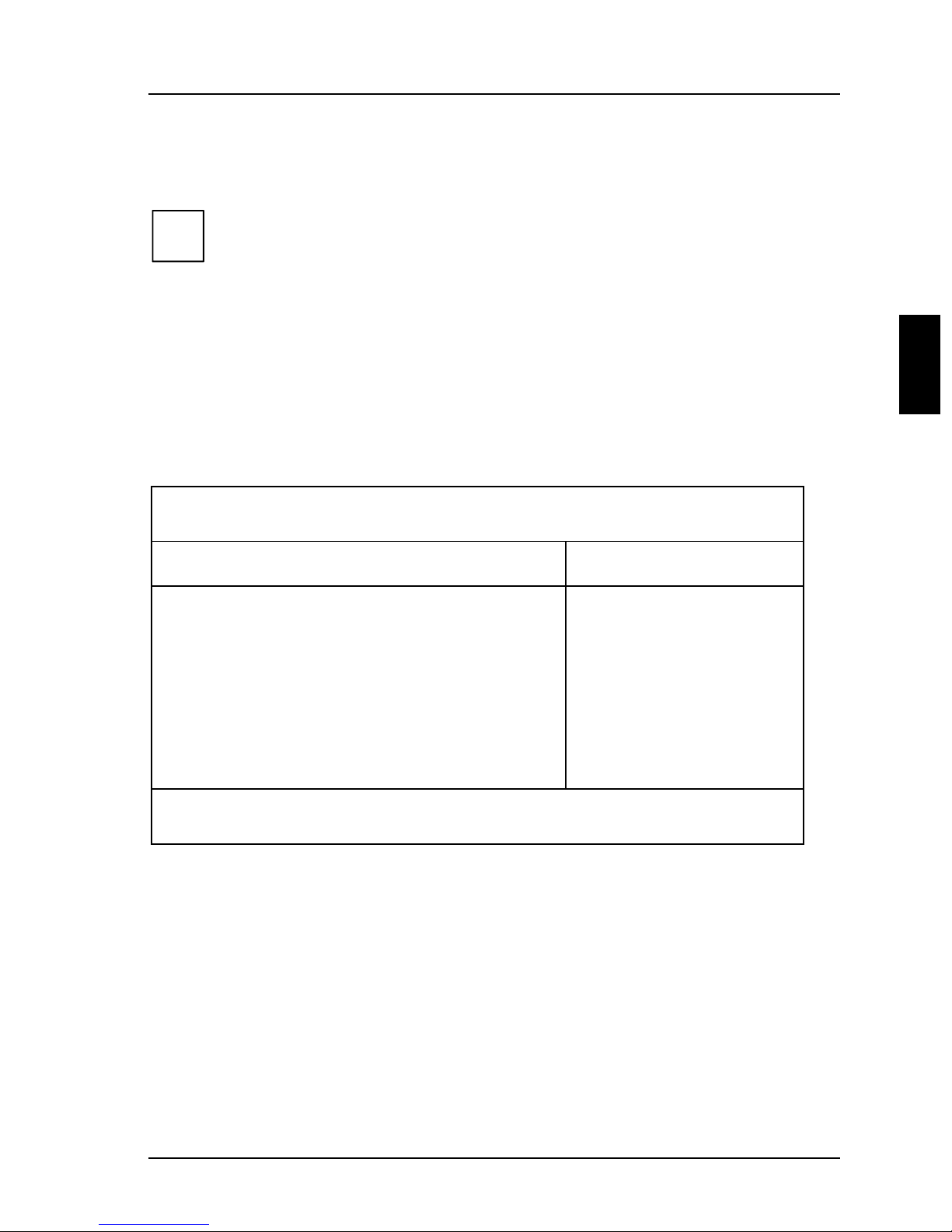
Exit menu
In the Exit menu, you can save your settings and exit BIOS Setup.
Phoenix BIOS Setup
Main Advanced Security Power BIOSFaX Exit
Save Changes & Exit
Discard Changes & Exit
Get Default Values
Load Previous Values
Save Changes
F1 Help ↑↓ Select Item -/+ Change Values F9 Setup Defaults
ESC Exit
Example for menu Exit
← → Select Menu Enter Execute Command F7 Previous Values
Item Specific Help
——————————————————————
Save Changes & Exit
saves the settings you have made and exits BIOS Setup.
Discard Changes & Exit
exits BIOS Setup without saving the new settings.
Get Default Values
reverts all settings to the default values.
Load Previous Values
sets the values which were in effect when BIOS Setup was called.
Save Changes
saves the settings you have made.
A26361-D943-Z120-14-7619 47
Page 56

Page 57

Settings with switch block S180
p
y
y
p
ON
1
234
OPEN/OFF
Switch1,2,3and4=clockspeed
Switch 5 = write protection for system BIOS
Switch 6 = must be set to off
678
5
Switch 7 = recovering System BIOS
Switch 8 = write protection for
floppy disk drive
Clockspeed-switch1,2,3and4
The switches mayonlybe set as specified in the table below for the
!
rocessor switch 1 switch 2 switch 3 switch 4
75 MHz on on off off
90 MHz on off off off
100MHz off on off off
120MHz on off on off
133MHz off on on off
150MHz on off on on
166MHz off on on on
200MHz off on off on
articularprocessor used.
If
ou want to replace theprocessor, contactyour sales outlet or our
service center, since
ou mayrequireavoltage converter.
A26361-D943-Z120-14-7619 49
Page 58

Settings with switch block S180
g
g
Write protection for System BIOS - switch 5
Switch 5 enables and disables system BIOS updating. Before an update of the
system BIOS can be carried out, write protection for the system BIOS must also be
disabled in the
Enabled). If you wish to update your system BIOS, please consult our customer
service.
on System BIOS is write protected.
off System BIOS can be overwritten (default setting).
Ifyou change the configuration ofyour system (for example byinstallin
!
new add-on boards),you must set switch 5 to off.Onlythenyou can
chan
BIOS Setup (in the Security menu,theFlash Write field must be set to
e the configurationdatainthesystem BIOS.
Recovering System BIOS - switch 7
Switch 7 enables recovery of the old system BIOS after an attempt to update has
failed. Write protection for the System BIOS must be disabled in the BIOS setup
and before the System BIOS can be recovered (switch 5 =
BIOS you need a Flash BIOS Diskette (call customer service).
on The System BIOS executes from floppy drive A: and restores the
System BIOS on the system board.
off The System BIOS is started from the system board (default
setting).
off). To restore the old
Write protection for floppy disk drive - switch 8
Switch 8 is used to define whether floppy disks can be written or deleted in the
floppy disk drive. To write and delete floppy disks, the write protection in
must be disabled (in menu Security,thefieldDiskette Write must be set to
setup
Enabled).
on The floppy disk drive is write-protected.
off Read, write and delete floppy disks is possible (default setting).
BIOS
50 A26361-D943-Z120-14-7619
Page 59

Add-on modules
y
y
k
y
1
8
7
1= FlashBIOS
2 = Lithium battery
3 = Processor with heat sink
4 = Locations bank 0 for main memory
2
3
4
5
6
5 = Locations bank 1 for main memory
6 = Location for second-level cache
7 = Socket for video memory
8 = Slot for wavetable board
Upgrading main memory
Four locations (bank 0 and bank 1) are available on the system board for installing
memorymodules. T he board supports a maximum of 128 Mbytes.
You may use memory modules of 4, 8, 16 or 32 Mbytes with or without parity
check.
You mayonlyuse fast memorymodules (access time = 70ns or less) or
!
EDO memor
In other words,
1. Pairs of memorymodules must have the same capacityand the same
access time.
The ECC error identification is onlypossible for modules withparit
i
A26361-D943-Z120-14-7619 51
checks
modules (access time = 60ns or less)
ou fit the firstpair to bank 0, and the secondpair in ban
Page 60

Add-on modules Upgrading main memory
Installing memory modules
1
2
Ê Insert the memory module at an angle into the appropriate location (1).
Ensure that the key notch and the two holes are correctly aligned with the
retaining pins.
Ê Tilt the module down until it snaps into place (2).
Removing a memory module
1
Ê Carefully push the retaining clips at each end of the module outwards (1).
Ê Tilt the memory module forwards (2), and pull it upwards and at an angle out
of the mounting location (3).
3
2
1
52 A26361-D943-Z120-14-7619
Page 61

Replacing the processor Add-on modules
t
y
p
y
Replacing the processor
3
1
Ê Push the lever in the direction of the arrow (1) and lift it as far as it will go
(2).
Ê Remove the old processor from the socket (3).
Ê Insert the new processor in the socket so that the mark on the upper side of the
processor matches the mark (A) on the socket (4).
Themarkontheprocessor maybe covered bya heat sink. In this case le
!
Ê Push the lever back down so that it snaps into place.
Ê Set the switches 1, 2 , 3 and 4 depending on the processor which is installed.
!
ourself beguided bythe markingin the rows ofpins on the underside of
the
rocessor.
Ifyou want to replace theprocessor, contactyour sales outlet or our
service center, since
2
ou mayrequireavoltage converter.
4
5
A
A26361-D943-Z120-14-7619 53
Page 62

Add-on modules Upgrading the second-level cache
y
pying
Upgrading the second-level cache
The system board has a socket for second-level cache. You can install a PipelinedBurst second-level cache module with 128 Kbytes, 256 Kbytes or 512 Kbytes.
To avoid damagetothesystem board onlycache modules released b
!
Siemens Nixdorf should be used.
1
1 = Installing second-level cache 2 = Removing second-level cache
Ê If a second-level cache is already installed, pull it out of the mounting location
in the direction of the arrow (2).
Ê Insert the new second-level cache module into the mounting location, making
sure it snaps into place (1).
To be able to use the second-level cache,you must set the Cache field
i
in the
Extern
BIOS Area
Enabled and co
cache.
Advanced / Cache Memory menu of the BIOS Setup to Intern and
. You can enhance theperformance bysettingthe Cache System
and Cache Video BIOS Area fields in the same menu to
ROM sections with Cache memory regions to the
2
Removing second-level cache modules
Ê Pull the second-level cache module out of the mounting location in the
direction o f the arrow.
Upgrading the video memory
If your system board is supplied with a video memory configuration of 1 Mbyte,
youmayenlargethevideomemoryupto2Mbytes.
54 A26361-D943-Z120-14-7619
Page 63

Upgrading the video memory Add-on modules
y
p
Information on which DRAM components (DRAM 256K*16 16ns)you
!
can use is available from
Note the location of the DRAM chi
A
our sales office or the customer service.
whenyouplugin DRAM chip!
Ê Insert the DRAM component in such a way in the socket for video memory
that the mark on the upper side of the DRAM component (A) matches the
position of the mark on the socket.
A26361-D943-Z120-14-7619 55
Page 64

Add-on modules Connecting an audio board
1
2
Game-Port Audio
Connecting an audio board
If an audio board is installed at the front of your system or you install one at the
front, you must attach the connecting line to the Game/Midi / Audio port on the
system board. The Game/Midi / Audio port is a combined plug.
Ê Plug the connecting line onto the side marked with Audio.
If an audio board is installed at the back of your system or you install one at the
back, you must attach the connecting line to the Game/Midi / Audio port on the
system board. The plug on the connecting line is exactly the same width as the
Game/Midi / Audio port.
Ê Plug the connecting line into the Game/Midi / Audio port.
56 A26361-D943-Z120-14-7619
Page 65

Replacing the lithium battery Add-on modules
p
y
y
p
g
y
p
Replacing the lithium battery
Incorrect replacement of the lithium batterymaylead to a risk of
ex
!
losion.
The lithium batter
type recommended bythe manufacturer (CR2032).
Do not throw lithium batteries into the trashcan. It must be dis
accordance with local re
Make sure that
must be on the to
+
+
must be replaced with an identical batteryor a batter
ulations concerningspecial waste.
ou insert the batterythe right wayround. Thepluspole
!
1
2
+
3
+
osed of in
Ê Lift the contact (1) a few millimeters and remove the battery from its socket
(2).
Ê Insert a new lithium battery of the same type in the socket (3).
A26361-D943-Z120-14-7619 57
Page 66

Page 67

Error messages
This chapter contains error messages generated by the system board.
Diskette drive A error
Diskette drive B error
Check the entry for the diskette drive in the Main menu of the BIOS Setup.
Check the connections to the diskette drive.
Extended RAM Failed at offset: nnnn
Failing Bits: nnnn
System RAM Failed at offset: nnnn
Switch the PC off and on again. If the message is still displayed, please
contact your sales office or customer service.
Fixed Disk 0 Failure
Fixed Disk 1 Failure
Fixed Disk Controller Failure
Check the entries for the hard disk drive in the Main menu of the BIOS Setup.
Check the hard disk drive's connections and jumpers.
Incorrect Drive A - run Setup
Incorrect Drive B - run Setup
Correct the entry for the diskette drive in the Main menu of the BIOS Setup.
Invalid NVRAM media type
Switch the PC off and on again. If the message is still displayed, please
contact your sales office or customer service.
Invalid System configuration Data
In the Advanced menu of the BIOS Setup set the entry for Reset Config Data to
Yes.
Keyboard controller error
Connect another keyboard. If the message is still displayed, please contact
your sales office or customer service.
Keyboard error
Check that the keyboard is connected properly.
Keyboard error nn
Release the key on the keyboard (nn is the hexadecimal code for the key).
Monitor type does not match CMOS - RUN SETUP
Correct the entry for the monitor type in the Main menu of the BIOS Setup.
A26361-D943-Z120-14-7619 59
Page 68

Error messages
Operating system not found
Check the entries for the hard disk drive and the floppy disk drive in the Main
menu of the BIOS Setup.
Parity Check 1
Parity Check 2
Switch the PC off and on again. If the message is still displayed, please
contact your sales office or customer service.
Previous boot incomplete - Default configuration used
By pressing function key [F2]
Setup. By pressing function key [F1]
configuration. If the message is still displayed, please contact your sales
office or customer service.
[F2] you can check and correct the settings in BIOS
[F2][F2]
[F1] the PC starts with incomplete system
[F1][F1]
Real time clock failure
Call the BIOS Setup and enter the correct time in the Main menu. If the
message is still displayed, please contact your sales office or customer
service.
System battery is dead - Replace and run SETUP
Replace the lithium battery on the system board and redo the settings in the
BIOS Setup.
System Cache Error - Cache disabled
Switch the PC off and on again. If the message is still displayed, please
contact your sales office or customer service.
System CMOS checksum bad - run SETUP
Call the BIOS Setup and correct the previously made entries or set the default
entries.
System timer error
Switch the PC off and on again. If the message is still displayed, please
contact your sales office or customer service.
60 A26361-D943-Z120-14-7619
Page 69

Index
2
!
2
i
Ê
Ë
ÚÚÚÚ
3
32 Bit I/O 16
5
528 Mbyte, hard disk capacity 16
A
Accumulator 9, 57
Additional system settings 29
Address 7
Addressing, IDE hard disk 15
Advanced BIOS Setup 19
Advanced Power Management, see APM interface
Advanced System Configuration 29
Advanced system settings 19
APM, interface 40
ASR&R Boot Delay 39
Assigning
Assignment
Audio board, connecting 56
Audio controller 3, 26
Audio input 3
Autotype Hard Disk 14, 15
Available
2
2
2
serial interface 24
PCI interrupts 28
PCI VGA interrupts 28
DMA channels 7
interrupt 7
A26361-D943-Z120-14-7619 61
Page 70

Index
base memory 18
extended memory 19
B
Base Memory 18
size 18
Battery
disposal 9, 57
replace 9, 57
Bidirection 25
BIOS Setup
advanced system settings 20
energy saving functions 40
Exit menu 47
exiting 47
floppy disk 50
Main menu 12
Menu Advanced 19
Menu BIOSFaX 45
Menu Power 40
Menu Security 33
security functions 33
settings 11
system configuration 11
write-protection 36
BIOS Update 50
Diskette 37
BIOSFaX 45
Board 4
safety 10
Boot Logo 17
Boot Options 16
Boot sector, changes 36
Boot Sequence 18
Boot, see also System startup
Booting
system 16, 17, 18
Buswidth, setting 16
C
Cache
62 A26361-D943-Z120-14-7619
Page 71

BIOS 21
Cache function 21
ROM areas 21
setting 54
Upgrading second-level cache 54
write-access 21
Cache - cache utilization 20
Cache memory 20
Cache Memory Regions 21
Cache mode 21
Cache Performance 30
Cache speed 30
Cache System BIOS Area 21
Cache Video BIOS Area 21
CD line-in, connector 3
CE certificate 9
Changes, boot sector 36
Chipcard 39
Chipcard reader 39
Chipset output current 30
Clock cycle, PCI slot 29
Clock speed
Switch 49
Computer virus 36
Configuration data, initializing 32
Configuration, BIOS Setup 11
Connecting, audio board 56
Connector 4
AUX-in 3
CD line in 3
Game/Midi 3
Game/Midi / Audio 57
voice modem 3
Controller
audio 26
drive 25
floppy disk drive 25
mouse 26
setting 23
USB 26
Current system status, saving 42
Index
A26361-D943-Z120-14-7619 63
Page 72

Index
Cylinders, hard disk parameter 15
D
Data transfer
parallel 25
setting mode 25
Date
changing 12
Date, changing 12
Default Latency Timer 29
DeskOff 37
Discard Changes & Exit 47
Diskette A/B 12
Diskette Controller 25
Diskette Lock 35
Diskette Write 36, 51
DRAM module 55, 56
DRAM Parity Check 30
Drive controller 25
setting 24
switching off 25
E
ECC 30, 51
ECP 25
Effect
setup password 34
System password 35
Energy saving 41
Energy saving functions
hard disk drive 42
setting 40
Energy saving mode 45
Enhanced Capability Port, see ECP
Enhanced Parallel Port, see EPP
EPP 25
Error Correction Code, see ECC
Error messages 59
Error recognition 52
ESD 10
Exit, BIOS Setup 47
64 A26361-D943-Z120-14-7619
Page 73

Exiting, BIOS Setup 47
Extended Memory 18
size 18
Extent, energy saving functions 41
External cache
second-level cache 20
setting 20
F
F1 11
F2 35
Fax Tone Count 46
Fax Modem Port 46
Feature Connector 30
Features 2
First-level cache
internal cache 20
setting 20
Flash BIOS
floppy disk 50
write-protection 36
Flash Write 36, 50
Floppy disk drive
type 13
write-protection 36, 50
Floppy disk drive controller 25
setting 25
Function key
F1 11
F2 36
Functionality, switching on/off 37
Index
G
Game/Midi / Audio 4, 56
Game/Midi, connector 3
Get Default Values 47
Graphics controller 3
screen resolutions 5
H
HAL 37
A26361-D943-Z120-14-7619 65
Page 74

Index
Hard disk
access 33
addressing 15
capacity 15
controller 25
energy saving functions 42
transfer mode 15
transfer rate 16
Hard disk drive 13
parameter 14
Hard disk parameter
cylinders 15
heads 15
sectors/track 15
write precomp 15
Hard Disk Timeout 42
Hard Disk Type 14
Hardware Abstraction Layer, see HAL
Heads, hard disk parameter 15
Help text, calling 11
I
IDE hard d isk drive, see Hard disk drive
IDE hard disk, see Hard disk
Important notes 9
Infrared interface 24
Initializing, configuration data 32
Installation
Setup password 34
System password 34
Installing
memory module 52
second-level cache 54
Internal cache
first-level cache 20
write-access 21
Interrupt 7
assigning 28
serial interface 24
Interrupt table 7
ISA memory area 30
66 A26361-D943-Z120-14-7619
Page 75

ISA Memory Gap 30
K
Keyboard
switching system off 38
switching system on 38
System password 35
L
Large Disk Access Mode 32
Latency Timer 29
LBA Translation 15
Lithium battery 9, 57
Load Previous Values 47
Location, switch block 49
Logical Block Addressing, see LBA
Loudspeaker, connector 3
Index
M
Main memory 51
upgrading 51
Main menu 11
Memory
base memory 18
cache 20
extended memory 18
main memory 18, 51
second-level cache 54
video memory 55
Memory area, ISA board 30
Memory Current 30
Memory module 51
installing 52
removing 53
Memory performance 30
Memory speed 30
Menu
Advanced 19
BIOS Setup 11
BIOSFaX 45
Exit 47
A26361-D943-Z120-14-7619 67
Page 76

Index
Main 11
Power 40
Security 33
Menu Security, Flash Write 50
Microphone jack 3
Modem mode 45
Modem, setting 45
Monitor, type 18
Mouse Controller 26
N
Notational conventions 1
Number
fax tone 46
ring tone 45
O
On/off switch 37
Operating system
starting 35
switching off 38
P
Parallel
data transfer 25
interface 24, 25
Parallel Mode 25
Parameter, hard disk drive 14
Parity check 30, 51
Parity Mode 30
Password
Setup password 34
System password 35
PCI 1
assigning interrupts 28
assigning VGA interrupts 29
Configuration 27
functionality 27
settings 28
PCI Device, Slot #n: 29
PCI Interrupt Mapping INTx# 28
68 A26361-D943-Z120-14-7619
Page 77

PCI slot
Default Latency Timer 29
Latency Timer 29
setting 29
Performance, increasing 16, 21, 22, 23, 30, 54
Peripheral Component Interconnect, see PCI
Peripheral Configuration 23
PIO Mode 16
Plug & Play O/S 31
Plug&Play, functionality 31
Port 4
parallel 25
serial 24
setting 23, 24, 25
Port, Fax Modem 46
POST Error Halt 17
Power Management Mode 41
Power On Source
Keyboard 38
Remote 38
Timer 39
Power ON/OFF 37
causes 37
system 37
Power Off Source
Keyboard 38
Software 37
Power, BIOS Setup 40
PressF2toenterSETUP 35
Primary connector, drive controller 26
Printer 25
Processor
clock speed 50
internal cache 20
replacing 53
Processor clock, standby function 42
Program, switching system off 37
Programmed Input Output Mode, see PIO
Index
Q
Quick boot 17
A26361-D943-Z120-14-7619 69
Page 78

Index
Quick selftest 17
Quiet boot 17
R
RAM 22
Random Access Memory, see RAM
Read Only Memory, see ROM
Real-time clock module 9, 57
Receive Mode 45
Recovering, System BIOS 50
Recycling, battery 9, 59
Remote Power On 38
Removing, memory module 52
Reset Configuration Data 32
Resource table 7
Ring Count 46
ROM 22
ROM areas 23
copying 22
S
S180 switch block 49
Save Changes 49
Save Changes & Exit 47
Save To Disk 42
SAVETO.DSK 44
Saving
current system status 42
settings 47
Screen resolutions 5
Secondary connector, drive controller 25
Second-level cache
external cache 20
setting 20
upgrading 54
write-access 21
Sectors/Track, hard disk p arameter 15
Security function, BIOS Setup 33
Selftest 16, 17
Sequence, system startup 18
Serial 1
70 A26361-D943-Z120-14-7619
Page 79

address 24
interrupt 24
switching off 24
Serial 2
address 24
interrupt 24
switching off 24
Serial 2 Mode 24
Serial interface 47
Serial port
setting 24
Set System Password 34, 37, 38, 39
Setting
Controller 23
drive controller 23
energy functions 40
internal cache 20
port 23
Second-level cache 20
Settings
Advanced Po wer Management 41
BIOS Setup 11
Power Management 40
Setup call 35
Setup message 33
Setup Password 33
effect 34
installing 34
SetupPasswordLock 34
Setup Prompt 35
Setup, see BIOS Setup
Shadow Memory 22
Shadow Memory Regions 23
Software, system switching off 37
Standby CPU Speed 42
Standby function, processor clock 42
Standby mode 41
Standby Timeout 41
Startup sequence 18
Storage capacity, hard disk 15
Suspend mode 42
Index
A26361-D943-Z120-14-7619 71
Page 80

Index
Suspend Timeout 41
Switch1,2,3and4
Clock speed 54
Switch 1, 2, 3 and 4, clock speed 49
Switch 5, write protection for System BIOS 50
Switch 7, System BIOS recovering 50
Switch 8, write protection for diskette drive 50
Switch block, Location 49
Switching off
audio controller 26
feature connector 31
mouse controller 26
Plug&Play 32
USB controller 27
Switching on
at a particular time 39
Audio controller 26
chipcard reader 40
feature connector 30
mouse controller 26
Plug&Play 31
USB controller 26
Switch-on time 39
SWOFF 37
System
halt 17
memory 51
power on/off 37
switching off via keyboard 38
switching off via software 37
switching on at a particular time 39
switching on remotely 38
switching on via keyboard 38
System activities, setting 44
System BIOS
recovering 50
write-protection 36, 50
System board, see board
System boot, see System startup
System configuration, BIOS Setup 11
System Date 12
72 A26361-D943-Z120-14-7619
Page 81

System Load 35
System Password 34
effect 35
installing 34
System Password Mode 35, 37, 38, 39
System settings
additional 30
advanced 19
System Shadow 22
System start
setting 17
System startup 16, 17, 18
System status 42
System switching off, keyboard 39
System Time 12
Index
T
Technical information 11
Test routine 16, 17
Time
changing 12
switching on at a particular time 39
Transfer mode 15, 21
hard disk 15
parallel port 25
Transfer rate, hard disk 16
Type of monitor 18
Type, Hard Disk Type 14
U
Update
BIOS 50
defective 50
Upgrading
Main memory 51
second-level cache 54
USB Controller 26
V
VGA interrupt 28
Video Display 18
A26361-D943-Z120-14-7619 73
Page 82

Index
Video memory, upgrading 54
Video Shadow 22
Video-BIOS 22
Virus Warning 36
Voice modem, connector 3
W
Wakeup Event 44
Wavetable module 3
Write Back 21
Write Precomp, hard disk parameter 15
Write protection
floppy disk drive 36, 50
system BIOS 36, 50
Write Through 21
74 A26361-D943-Z120-14-7619
 Loading...