

Page 1

Mainboard
Short Description
Mainboard D3641/D3642/
D3643/D3644/D3646
Page 2

Congratulations on buying
an innovative
product from Fujitsu.
The latest information about our products, tips, updates etc. can be found
on the Internet at: "
http://www.fujitsu.com/fts/"
For driver updates, go to: "http://support.ts.fujitsu.com/download"
Should you have any technical questions, please contact:
• our Hotline/Service Desk ("
http://support.ts.fujitsu.com/contact/servicedesk")
• Your sales partner
• Your sales office
We hope you enjoy working with your new Fujitsu system!
Page 3

Page 4
Published by / C ontact address in the EU
Fujitsu Te
chnology Solutions GmbH
Mies-van-der-Rohe-Straße 8
80807 Munich, Germany
"
http://
www.fujitsu.com/fts/"
Copyright
©Fujits
u Technology Solutions GmbH 2018. All rights reserved.
Publication Date
08/2018
Order No.: A26361-D3641-Z320-1-7419, edition 1
Page 5
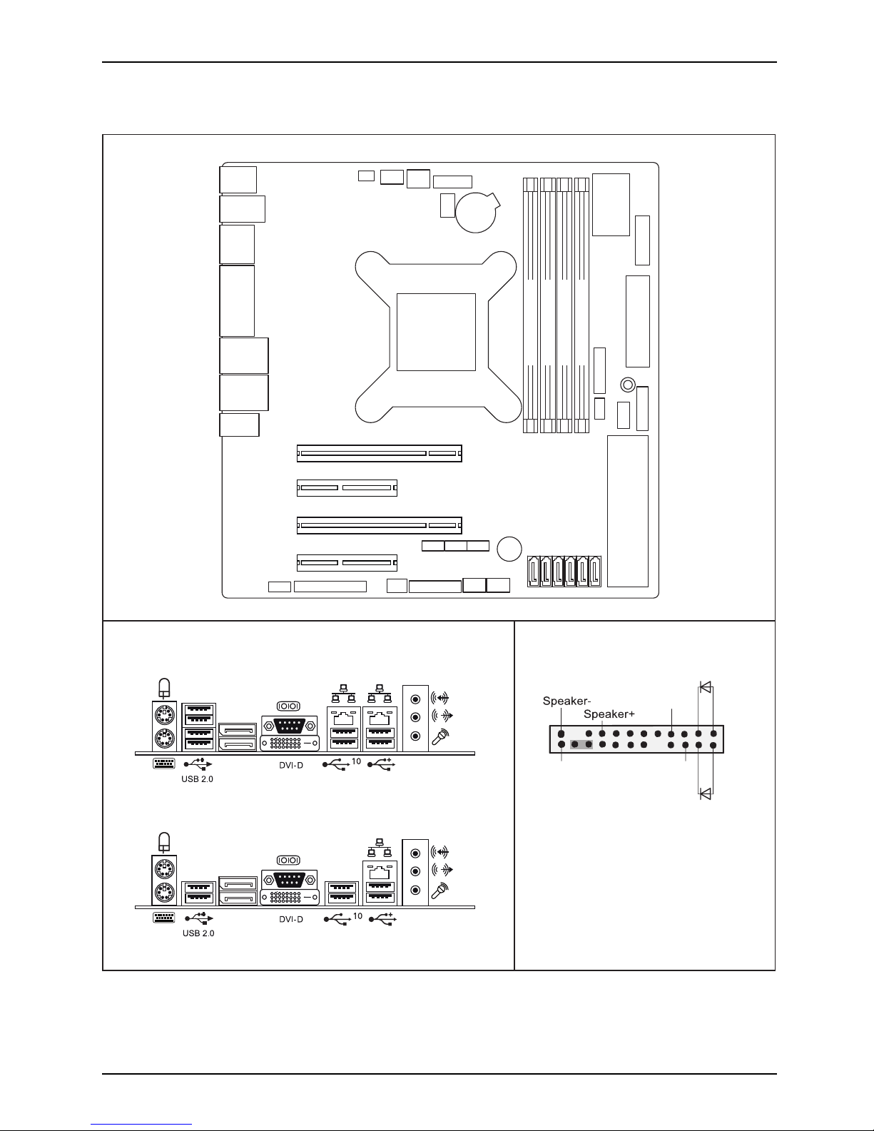
Internal co nnectors an d slots
External connectors rear
Front panel
PS2
USB 2.0
COM /
DVI-D
CPU
LAN 1
USB 3.1
Gen 1
Audio
Audio
Frontpanel
S/PDIF
FAN 3
SLOT3 x4 + EDP
SLOT4 x1
SLOT2 x1
SLOT1 x16
FAN 2
COM2
LPT
SATA4
ATX POWER
+12V
Buzzer
PC98
Battery
D3641/D3642/D3643/D3644
GPIO
D3641
D3642/D3643/D3644
DP
FAN 1
FAN 4
INTR
SATA5
SATA3
SATA0
SATA1
SATA2
Front panel
COM3 COM4
M.2 SSD
2280
M.2
WLAN
USB 3 Int.1
USB 3 Int.2
USB
USB
Stick
DP
(Displayport)
DP
(Displayport)
Channel B, Slot 2
Channel
B, Slot 4
Channel
A, Slot 1
Channel
A, Slot 3
USB 3.1
Gen 2
USB 3.1
Gen 1
USB 3.1
Gen 1
LAN 2
USB 3.1
Gen 2
USB 3.1
Gen 2
Recovery inserted = The system starts
from USB stick and allows a BIOS recovery.
Details can be found in the BIOS manual.
1
2
HD-LED
Recovery
Reset
Power
On/Off
Power LED
Fujitsu
Page 6
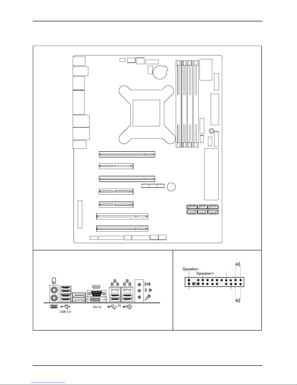
Internal connectors and slots
External connectors rear
Front panel
PS2
USB 2.0
COM /
DVI-D
CPU
LAN 1
USB 3.1
Gen 1
Audio
Audio
Frontpanel
S/PDIF
FAN 3
SLOT3 x4 + EDP
SLOT4 x1
SLOT2 x1
SLOT1 x16
FAN 2
COM2
LPT
SATA4
ATX POWER
+12V
Buzzer
PC98
Battery
D3646
GPIO
D3646
DP
FAN 1
FAN 4
INTR
SATA5
SATA2
SATA1
SATA0
Front panel
COM3 COM4
M.2 SSD
2280
M.2
WLAN
USB 3 Int.1
USB 3 Int.2
USB
USB
Stick
DP
(Displayport)
Channel B, Slot 2
Channel
B, Slot 4
Channel
A, Slot 1
Channel
A, Slot 3
USB 3.1
Gen 2
USB 3.1
Gen 1
LAN 2
USB 3.1
Gen 2
Label
SLOT5 x1
SLOT6 PCI1
SLOT7 PCI2
SATA3
Recovery inserted = The system starts
from USB stick and allows a BIOS recovery.
Details can be found in the BIOS manual.
1
2
HD-LED
Recovery
Reset
Power
On/Off
Power LED
Fujitsu
Page 7

Internal co nnectors an d slots
List of onboard Features D3641 D3642 D3643
CPU Socket max. 95W
TDP
H4-LGA1151 H4-LGA1151 H4-LGA1151
Chipset Intel® C246 Intel® Q370 Intel® B360
Memory Speed 2133 / 2400 / 2666 2133 / 2400 / 2666 2133 / 2400 / 2666
Memory DDR4 Slots
444
Board size μATX μATX μATX
DVI-D 1 1 1
DP (Displayport)
222
Multichannel Audio 5.1 5.1 5.1
Audio SPDIF Output Yes No No
Audio Buzzer Magnetic
--
Internal Speaker S
upport
2W / 4Ohm 2W / 4Ohm 2W / 4Ohm
LAN: Speed
10Mbit / 100Mbit /
1000Mbit
10Mbit / 100Mbit /
1000Mbit
10Mbit / 100Mbit /
1000Mbit
LAN 1: Controller I219LM I219LM I219LM
LAN 2: Controll
er I210
--
iAMT (Version)
12.0 12.0
-
M.2 2280 SSD Connecto r PCIe3.0 / 4 lanes PCIe3.0 / 4 lanes
PCIe3.0 / 4 lanes
(2280/22110 support)
Intel® Opt
ane Support Yes Yes Yes
M.2 2230 W
LAN,
Bluetoot
h® Connector
PCIE3.0 /USB 2. 0 PCIE3.0 /U SB 2.0
-
SATA 6 Gb/s Ports
1
664
Supported RAID Levels 0,1,5,
10
0,1,5,
10
-
PCIe Sp
eed
3.0 / 2.
0
3.0 / 2.
0
3.0 / 2.
0
Supported USB Speed
USB2.0 /
USB3.1 Gen1 (5 Gbit) /
USB3.1 Gen2 (10
Gbit)
USB2.0 /
USB3.1 Gen1 (5 Gbit) /
USB3.1 Gen2 (10
Gbit)
USB2.0 /
USB3.1 Gen1 (5 Gbit) /
USB3.1 Gen2 (10
Gbit)
PS2 Port Keyboard / Mouse Keyboard / Mouse Keyboard / Mouse
COM
Port 1 external external external
COM Port 2
internal No No
COM Port 3 i
nternal
N
o
N
o
C
OM Port 4 internal No No
Parallel Internal Connector
Yes No No
CPU FAN 1
2
Yes Yes Yes
FAN 2 Yes Yes Yes
FAN 3 Yes Yes No
PSU FAN 4
2
Yes
3
No No
FAN Control Silent FAN Silent FAN Silent FAN
Extended Lifetime
Yes Ye s Yes
Fujitsu
Page 8

Internal connectors and slots
List of onboard Features D3641 D3642 D3643
TPM Onboard SLB9670SPI SLB9670SPI
Intel chipset
integrated
BIOS Features
Recovery BIOS / Desk
Update / Multi Boot
Recovery BIOS / Desk
Update / Multi Boot
Recovery BIOS / Desk
Update / Multi Boot
HDD Passw ord Yes Yes Yes
1
maximum supported transfer rate per port / interface
2
monitored and controlled
3
ifsupportedbyusedpsu
Fujitsu
Page 9

Internal co nnectors an d slots
List of onboard Features D3644 D3646
CPU Socket, max. 95W TDP H4-LGA1151 H4-LGA1151
Chipset Intel® C246 Intel® C246
Memory Speed 2133 / 2400 / 2666 2133 / 2400 / 2666
Memory DDR4 Slots
44
Board size μATX ATX
DVI-D 1 1
DP (Displayport)
22
Multichannel Audio 5.1 5.1
Audio S PDIF Output No Yes
Audio Buzzer
-
Magnetic
Internal Speaker Su
pport
2W / 4Ohm 2 W / 4Ohm
LAN: Speed 10Mbit / 100Mbit / 1000Mbit 10Mbit / 100Mbit / 1000Mbit
LAN 1: Controller I219LM I219LM
LAN 2: Controll
er
-
I210
iAMT (Version)
12.0 12.0
M.2 2280 SSD Connector PCIe3.0 / 4 lanes PCIe3.0 / 4 lanes
Intel® Optan
e Support Yes Yes
M.2 2230 WLAN, Bluetooth® C onnector PCIE3.0 /U SB 2.0 PCIE3.0 /USB 2.0
SATA 6 Gb/s Ports
1
66
Supporte
d RAID Levels 0,1,5,10 0,1,5,10
PCIe Speed 3.0 / 2.0 3.0 / 2.0
Supported USB Speed
USB2.0 /
USB3.1 Gen1 (5 Gbit) /
USB3.1 Gen2 (10 Gbit)
USB2.0 /
USB3.1 Gen1 (5 Gbit) /
USB3.1 Gen2 (10 Gbit)
PS2 Po
rt
Keybo
ard / Mouse
Keybo
ard / Mouse
COM Port 1
external external
COM Port 2 No int
ernal
COM
Port 3 No internal
COM Port 4
No internal
Parallel Internal Connector N
o
Y
es
C
PU FAN 1
2
Yes Yes
FAN 2 Yes Yes
FAN 3 Yes Yes
PSU FAN 4
2
No Yes
3
FAN Control Silent FAN Silent FAN
Extended Lifetime Yes Yes
TPM Onboard SLB9670SPI SLB9670SPI
BIOS Features
Recovery BIOS / Desk
Update / Multi Boot
Recovery BIOS / Desk
Update / Multi Boot
HDD Password Yes Yes
Fujitsu
Page 10

Internal connectors and slots
1
maximum supported transfer rate per port / interface
2
monitored and controlled
3
ifsupportedbyusedpsu
Special Features
Silent Fan OS Independent, temperature related full featured silent fan control
System Guard View and adjust Silent Fan (only O EM version) / Silent Fan LT
Silent Drives Noise reduction for optic
al and hard disk drives
Recovery BIOS Restores a corrupted BIOS
Desk Update Simple driver update with DU DVD
Multi Boot
Comfortable boot from
any boot device
HDD Passwort
Access pro tection for disk drives
Silent Fan LT OS Independent, temperature related silent fan control
Keyboard Power
Button
Fujitsu Technology Solutions Keyboard Power Button Support
Low Power Soft Of
f Reduced Energy consumption in shut down
USB Power Off Enable/Disable USB Power via BIOS in shut down mode
Support for FTS PCIe
VGA card
Optional D3653 VGA card must be equipped on PCI e x4 (mechanical
x8) Slot
Low Power Active
Mode
Special sleep
mode, which replaces the conventional Windows sleep
mode in order
to significantly reduce the idle power consumption.
Low Power Ac
tive Mo de is managed with the Workplace Power and
Communicat
ion S ett ings utility, which can be found in the Control Panel in
the System a
nd Security category.
Risk of Explosion if battery is replaced by an incorrect type.
Dispose of used batteries according to the instructions.
Il y a risque d’explosion si la batterie est remplacée par une batterie de type incorrect.
Mettre au rebut les batteries usagées conformément aux instructions.
Expl
osionsgefahr, wenn die Batterie mit einem inkorrekten Batterietyp ersetzt wird.
Alte
Batterien gemäß Gebrauchsanweisung entsorgen.
Fujitsu
Page 11

Mainboard D3641/D3642/
D3643/D3644/D3646
First-time setup
Deutsch 9
English 17
Page 12

Page 13

Inhalt Deutsch - 1
DeutschInhalt
Kurzbeschreibung des Mainboards .................................................... 3
Anschlüsse und Steckverbinder . ....................................................... 4
Prozessorein-/ausbauen ............................................................... 5
Technische Daten ....................................................................... 5
Vorgehensweise . . ...................................................................... 6
Hauptspeicher ein-/ausbauen .......................................................... 7
BIOS Update ........................................................................... 8
BIOS-Update unter Windows mit dem Pro gramm DeskFlash . . ............................. 8
BIOS-Update mit einem USB-Stick ....................................................... 8
Fujitsu 9
Page 14

Bemerkung
Hinweise zur Produktbeschreibung entsprechen den Designvorgaben von F ujitsu und
werden zu Vergleichszwecken zur Verfügung gestellt. Die tatsächlichen Ergebnisse
können aufgrund mehrerer Fakt oren abweichen. Änderungen an technischen Da ten ohne
Ankündigung vorbehalten. Fujitsu w eist jegliche Verantwortung bezüglich technischer
oder redaktioneller Fehler bzw. Auslassungen von sich.
Warenzeichen
Fujitsu und das Fujitsu-Logo sind eingetragene Warenzeichen von F ujitsu
Limited in Japan und in anderen Länd ern.
Die Bluetooth
®
Wortmarke und Logos sind eingetragene Warenzeichen der Bluetooth SIG, Inc.
Intel ist eine Marke der Intel Corporation in den USA und/oder anderen Lände rn.
Microsoft und Windows sind registrierte oder nicht registrierte Marken der Microsoft
Corporation in den US A und/oder in anderen Ländern.
PCI EXPRESS und PCIE sind registrierte Marken der PCI-SIG in den USA und in anderen Ländern.
SATA ist ein Produktname der SATA-IO.
Andere erwähnte Produkt- und Firmennamen sind Marken oder eingetragene Marken
der entsprechenden Firmen oder Markeninhaber.
Copyright
Ohne vorherige schriftliche Genehmigung von Fujitsu darf kein Teil dieser Veröffentlichung
kopiert, reproduziert oder übersetzt werden.
Ohne schriftliche Genehmigung von Fujitsu darf kein Teil dieser Veröffentlichung auf irgendeine
elektronische Art und Weise gespeichert oder übertragen werden.
Page 15

Kurzbeschreibung des Mainboards De
utsch - 3
Kurzbeschreibung des Mainboa
rds
Hinweise zu den Baugruppen
Beachten Sie bei Baugruppen mit EGB unbedingt Folgendes:
• Sie müssen sich statisch entladen (z. B. durch Berühren eines geerdeten
Gegenstands), bevor Sie mit Baugruppen arbeiten.
• Verwendete Geräte und Werkzeuge müssen frei von statischer Aufladung sein.
• Ziehen Sie den N etzstecker, bevor Sie Baugru ppen stecken oder ziehen.
• Fassen Sie die Baugruppen nur am Rand an.
• Berühren Sie keine An schluss-St ifte oder Leiterbahnen auf der Baugruppe.
Eine Übersicht der Leistungsmerkmale finden Sie im D atenblatt.
Besondere Merkmale
Ihr Mainboard ist in verschiedenen Ausbaustufen erhältlich. Abhängig von der Kon figuration
Ihres Mainboards besitzt oder unterstü tzt das Mainboard bestimmte Merkmale.
In diesem Handbuch finden Sie die wichtigsten Eigenschaften dieses Mainboards beschrieben.
Weitere Informationen zu Mainboards finden Sie im Internet unter: "
http://www.fujitsu.com/fts/products".
Fujitsu 11
Page 16

4 - Deutsch Anschlüsse und Steckverb
inder
Anschlüsse und Steckverbinde
r
Die Position der Anschlüsse und Steckverbinder Ihres Mainboards finden
Sie am Anfang des Handbuches.
Die markierten Komponenten und Steckverbinder müssen nicht auf
dem M ainb oard vorhanden sein.
Externe Anschlüsse
Die Position der externen Anschlüsse Ihres Mainboards finden Sie am Anfang des Handbuches.
PS/2-Tastaturanschluss,
violett
PS/2-Mausanschluss, grün
LAN-Anschluss (RJ-45) Mikrofonanschluss, rosa
Audioeingang (Line in),
hellblau
Audioausgang (Line out),
hellgrün
Buchse Typ A schwarz: Universal Serial Bus –
USB 2.0
Buchse Typ A blau: Universal Serial Bus –
USB 3.1 Gen 1
Serielle Schnittstelle, türkis Buchse Typ A rot: Universal Serial Bus –
USB 3.1 Gen 2
DP Displayport DVI – D
12 Fujitsu
Page 17

Prozessor ein-/ausbauen Deutsch - 5
Prozessor ein-/ausbauen
Für alle hier beschriebenen Arbeiten muss Ihr Syste m vollständig von d er Netzspannung
getrennt sein! Nähere Angaben dazu finden Sie in der Betriebsan leitung Ihres Systems.
Technische Daten
• Sockel LGA 1150, max. 95 W
• Eine aktuelle Liste der von diesem Mainboard unterstützten Prozessoren finden Sie
im Internet unter: "
http://www.fujitsu.com/fts/products".
Fassen Sie auf keinen Fall die Unterseite des Prozessors an. Schon leichte
Verunreinigungen wie Fett von der Haut können die Funktion des Prozessors
beeinträchtigen oder den P rozessor zerstören. Setzen Sie den Prozessor mit
großer Sorgfalt in den Steckplatz, d a die Federkonta kte des Steckplatzes sehr
empfindlich sind und nicht verbogen werden dürfen.
Sind ein oder mehrere Federkontakte verbogen, setzen Sie auf keinen Fall
den Prozessor ein, da dieser dadurch beschädigt werden könnte. Wenden
Sie sich bitte direkt an Ihren zuständigen Händler.
Fujitsu 13
Page 18

6 - Deutsch Prozessor ein-/ausb auen
Vorgehensweise
Der Steckplatz für den Prozessor ist zum Schutz der Federkontakte mit einer
Schutzkappe abgedeckt. Im Garantiefall kann das Mainboard nur mit befestigter
Schutzkappe von Fujitsu Technology Solutions zurück genommen werden!
a
b
► Entfernen Sie den Kühlkörpe
r.
► Drücken Sie auf den Hebel und
haken Sie ihn aus.
► Klappen Sie die Halterun
g nach oben.
► Entfernen Sie die Schutzkappe und
verwahren Sie diese.
► Halten Sie den Prozesso
r mit Daumen
und Zeigefinger und ste
cken Sie ihn
so in den Steckplatz (
b), dass die
Markierung des Proze
ssors mit de r
Markierung am Steck
platz von der Lage
her übereinstimmt (
a).
► Drücken Sie den Hebel nach unten,
bis er wieder einhakt.
Bitte beachten
Sie, dass je nach verwendetem Kühlkörper unterschiedliche
Kühlkörperhal
terungen auf dem Mainboard benötigt werden.
► Je nach Ausbau-Variante müssen Sie eine Schutzfolie vom Kühlkörper abziehen oder den
Kühlkörper mit Wärmeleitpaste bestreichen, bevor Sie ihn aufsetzen .
► Befestigen Sie den Kühlkörper - je nach Ausführung - mit vier Schrauben
oder stecken Sie ihn in die Befestigungen.
14 Fujitsu
Page 19

Hauptspeicher ein-/ausbauen Deuts
ch - 7
Hauptspeicher ein-/ausbauen
Technische Daten
Technologie
DDR4 2133/24 00/2666 MHz ungepufferte DIMM/SO-DIMM Module
260-Pin; 1.2V; 64 Bit ohne ECC, D3641-S/D3644-B/D3646-S mit ECC
Gesamtgröße 1 bis 64GByte
Modulgröße 1, 2, 4, 8 oder 1 6 GByte pro Modul
Eine aktuelle Liste der für dieses Mainboard empfohlenen Speichermodule finden Sie
im Internet unter: "
http://www.fujitsu.com/fts/products".
Es muss mindestens ein Speichermodul eingebaut sein. Speichermodule mit
unterschiedlicher Speicherkapazität können kombiniert werden.
Es dürfen nur ungepufferte DDR4-Speichermodule ohne ECC verwendet werden.
DDR4-Speichermodule müssen der DDR4-2 133-, DDR4-2400 oder
DDR4-2666-Spezifikation entsprechen.
DDR4-2133 Module sind abwärtskompatibel und werden a bhängig v on der CPU
betrieben.
Wenn Sie mehr als ein Speichermodul verwenden, dann achten Sie darauf,
die Speichermodule auf beide Speicherkanäle aufzuteilen. Dadurch nutzen
Sie die Performancevorteile des Dual-Channel-Mode.
Die maximale Systemperformance ist gegeben, wenn in Channel A und
Channel B identische Speichermodule verwendet werden.
Um die Bestückung zu erleichtern, sind die Steckplätze (Slots) farbig gekennzeichnet.
Abhängig von der Systemkonfiguration kann sich der sichtbare Hauptspeicher reduzieren.
Channel B, Slot 2
Channel B, Slot 4
Channel A, Slot 1
Channel A, Slot 3
Anzahl der gesteckten Speichermodule
Zu verwendender Steckplatz 1 2 3 4
Channel A, Slot 1
xxxx
Channel B, Slot 2
xxx
Channel A, Slot 3
xx
Channel B, Slot 4
x
Fujitsu 15
Page 20

8 - Deutsch BIOS Update
BIOS Update
Wann sollte ein BIOS-Upd ate durchge führt werden?
Fujitsu Technology Solutions stellt neue BIOS-Versionen zur Verfügung, um die Kompatibilität
zu neuen Betriebssystemen, zu neuer Software ode r z u neuer Hardware zu gewährleisten.
Außerdem können neue BIOS-Funktionen integriert werden.
Ein BIOS-Update sollte auch immer dann durchgef ührt werden, wenn ein Problem be steh t,
das sich durch neue Treiber oder neue Software nicht beheben lässt.
Wo g ibt es BIOS-Updates?
Im Internet unter "
http://support.ts.fujitsu.com/" finden Sie die BIOS-Updates.
BIOS-Update unter
Windows mit dem
Programm DeskFlash
Ein BIOS-Update
kann unter Windows auch mit dem Programm DeskFlash durchgeführt werden.
Das Programm Des
kFlash finden Sie auf dem Datenträger "Drivers & Utilities" (unter Flash BIOS).
oder
► Laden Sie die Up
date-Datei für "Flash BIOS Update – Desk Flash Instant"
von unserer In
ternet-Seite auf Ihren PC.
► Führen Sie d ie Update-Datei aus.
► Folgen Sie de
n Bildschirmanweisungen.
BIOS-Update mit einem USB-Stick
► Halten Sie einen FAT32-formatierten USB-Stick bereit.
► Laden Sie
die Zip-Datei "Admin package - Compressed Flash Files" von
unserer I
nternet-Seite auf Ihren PC.
► Entpacken Sie die ZIP-Datei und kopieren Sie die Dateien auf Ihren USB-Stick.
Auf dem U
SB-Stick befinden sich danach folgende Dateien:
• EfiFlash.efi im Ordner EFI/FUJITSU
•BIOS-U
pdate-Datei (z. B. D1234-A1.UPD) im Hauptverzeichnis des U SB-Sticks
► Starten Sie den PC neu und drücken Sie die Taste
F12
um das Boot-Menü zu öffnen.
► Wähle
n Sie mit den Pfeiltasten "FUJITSU Update Utility" aus und
best
ätigen Sie mit der Taste
Enter
.
► Bestätigen Sie den Update-Vorgang mit der Taste
Y
, wenn Sie dazu aufgefordert werden.
Es er
folgt ein Neustart, um das Update durchzuführen.
16 Fujitsu
Page 21

Contents English - 1
EnglishContents
Brief description of mainboard . . ....................................................... 3
Interfaces and connectors . . ........................................................... 4
Installing/removing the processor . . . ................................................... 5
Technical data .......................................................................... 5
Procedure . . . . .......................................................................... 6
Installing/removing main memo ry . . . ................................................... 7
BIOS Update ........................................................................... 8
BIOS update under Windows w ith DeskFlash program . .................................... 8
BIOS update using aUSBstick .......................................................... 8
Fujitsu 17
Page 22

Remarks
Product description information corresponds to the design requirements of Fujitsu and is
provided for the purposes of comparison. T he actual results may differ due to several
factors. Subject to changes to technical data without prior notification. Fujitsu accepts no
responsibility with regard to technical or editorial mistakes or omissions.
Trademarks
Fujitsu and the Fujitsu logo are registered trademarks of Fujitsu Limited in
Japan and in other countries.
The Blueto oth
®
word mark and logos are registered trademarks of Bluetooth SIG, Inc.
Intel is a trademark of the Intel Corporation in the USA a nd/or other countries.
Microsoft and Windows are registered or unregistered trademarks of the Microsoft
Corporation in the USA and/or in other countries.
PCI EXPRESS and PCIE are registered trade marks of t he PCI SIG in the USA and in other countries.
SATA is a product name of the SATA-IO.
Other product names and company names mentioned are trademarks o r registered
trademarks of the corresponding companies or trademark owners.
Copyright
No part of this publication m ay be copied, reproduced or translated without
the prior, written consent of Fujitsu.
No part of this publication m a y be saved or transmitted by any electronic means
without the written consent of Fujitsu.
Page 23

Brief description of mainboard Engl
ish - 3
Brief description of mainboar
d
Information about boards
Be sure to observe the following for boards with ESD:
• You must always discharge static build up (e.g. by to uch ing a grounded object)
before working with the board.
• The equipment and tools you use must be free of static charge.
• Remove the power plug from the mains supply before inserting or removing
boards.
• Always hold boards by their edges.
• Never touch connector pins or conductors on the board.
An overview of the features is provided in the data sheet.
Special features
Your mainboard is available in different configuration levels. Depending on the configuration,
your mainboard will be equipped with or provide support for certain features.
This manual describes the most important properties of this mainboard.
You can find more information on mainboards on the Internet at: "
http://www.fujitsu.com/fts/products".
Fujitsu 19
Page 24

4 - English Interfaces and connector
s
Interfaces and connectors
The location of the interfaces and connectors of your mainboard is sp ecified
at the beginning of the manual.
The components and connectors marked are not necessarily present on the mainboard.
External ports
The location of the external connections of your mainboard is specified at the beginning of the manual.
PS/2 keyboard port, purple PS/2 mouse port, green
LAN port (RJ-45)
Microphone p o rt, pink
Audio input (Line in), light
blue
Audio output (Line out),
light green
Socket type A, black: Universal Serial Bus –
USB 2.0
Socket type A, blue: Universal Serial Bus –
USB 3.1 Gen 1
Serial port, turquoise Socket type A, red: Universal Serial Bus –
USB 3.1 Gen 2
DP DisplayPort DVI – D
20 Fujitsu
Page 25
Installing/removing the processor
English - 5
Installing/removing the proc
essor
Disconnect the system from the mains voltage before performing any of the tasks
described below. Details are contained in the operating manual of your system.
Technical data
• Socket LGA 1150, max. 95
W
• A current list of the processors supported by this m ainboard is available on the
Internet at: "
http://www.fujitsu.com/fts/products".
Never touch the underside of the processor. Even minor soiling such as grease
from the skin can impair the processor’s operation or destroy the processor.
Place the processor in the socket with extreme care, as the spring contacts
of the socket are very delicate and must not be bent.
If one or more spring contacts are bent d o not insert the processor in any case as
it may be dama ged by doing so. Please contact the responsible dealer.
Fujitsu 21
Page 26

6 - English Installing/removing the
processor
Procedure
The processor socket is covered with a protective cap to protect the spring
contacts In the event of a warranty case, the m ainboard can only be taken back
by Fujitsu Technology Solutions with the protective cap secu red!
a
b
► Remove the heat sink.
► Press down the lever and unhook it.
► Fold up the frame.
► Remove the protective cap and keep it.
► Hold the processor between your thumb
and index finger and insert it into the socket
(b) so that the marking of the processor is
aligned with the marking on the socket (a).
► Press the lever downward until it is
hooked in again.
Please note that, depending on the heat sink used, different heat sink
mounts are required on the mainboard.
► Depending on the configuration variant, you must p ull a protective foil off the heat sink
or coat the heat sink with heat conducting paste before fitting it.
► Secure the heat sink - depending on the model - with four screw s or push it into the mounts.
22 Fujitsu
Page 27

Installing/removing main memo ry En
glish - 7
Installing/removing main mem
ory
Tech nic al data
Technology
DDR4 2133/2400/2666 MHz unbuffered DIMM/SO-DIMM modules
260 pin; 1.2V; 64-bit without ECC, D3641-S/D3644-B/D3646-S with
ECC
Tot al s iz e
1 to 64GB
Module size
1, 2, 4, 8 or 16 G B per module
A current list of the memory modules recommended for this mainboard is available
on the Internet at: "
http://www.fujitsu.com/fts/products".
At least one memory module must be installed. Memory modules with different
memory capacities can be combined.
Only unbuffered DDR4 memory modules without ECC may be used.
DDR4 memory modules must comply with the DDR4-2133, DDR4-2400
or DDR 4-266 6 specification.
DDR4-2133 modules are downward compatible and are operated depending on the CPU.
If you use more than one memory module, then make sure to distribute the
memory modules over both memory channels. By doing this you use the
performance advantages of the dual-channel mode.
Maximum system performance is achieved when identical memory modules
are used in Channel A and Channel B.
To simplify equipping, the slots are colour coded.
Depending on how the system is configured, the visible main memory can be reduced.
Channel B, Slot 2
Channel B, Slot 4
Channel A, Slot 1
Channel A, Slot 3
Number of memory modules inserted
Slot to be used 1 2 3 4
Channel A, slot 1
xxxx
Channel B, slot 2
xxx
Channel A, slot 3
xx
Channel B, Slot 4
x
Fujitsu 23
Page 28

8 - English BIOS Update
BIOS Update
When should a BIO S update be performed?
Fujitsu Technology Solutions makes new BIOS versions available to ensure compatibility with new
operating systems, new software or ne w hardware. In addition, new BIOS functions can be integrated.
A BIOS update should also always be performed if there is a problem that cannot
be solved using new drivers or new software.
Where can I obtain BIOS updates?
You can find the BIOS updates on the Internet at "
http://support.ts.fujitsu.com/".
BIOS update under Wi
ndows with DeskFlash program
A BIOS update can also be carried out under Windows with the DeskFlash program. The DeskFlash
program is located on the "Drivers & Utilities" data carrier (under Flash BIOS).
or
► Download the "Flash BIOS Update – Desk Flash Instant" update file from our website to your PC.
► Run the update file.
► Follow the on-screen instructions.
BIOS update using a USB stick
► Have a FAT32 formatted USB stick ready.
► Download the ZIP file "Admin package - Compressed Flash Files" from our website to your PC.
► Unzip the ZIP file and copy the files onto your USB stick.
The following files will then be on your USB stick:
• EfiFlash.efi in the folder EFI/FUJITSU
• BIOS update file (e.g. D1234-A1.UPD) i n the root directory of the USB stick
► Reboot the PC and press the
F12
key to open the Boot menu.
► Use the arrow keys to select "FUJITSU Update Utility" and confirm with the
Enter
key.
► Confirm the update process with the
Y
key when you are prompted to do so.
A restart occurs to perform the update.
24 Fujitsu
 Loading...