

Page 1
TechNotes V1.2
Industrial Mainboard Series
D3231-S
D3235-S
D3236-S
D3243-S
Page 2
a
Content
1
Safety Instructions 6
2
Feature Overview 7
2.1 Basic Layout D3231-S 11
2.2 Basic Layout D3235-S 12
2.3 Basic Layout D3236-S 13
2.4 Basic Layout D3243-S 14
2.5 Block Diagram D3231-S & D3236-S 15
2.6 Block Diagram D3235-S 16
2.7 Block Diagram D3243-S 17
2.8 External Connectors D3231-S / D3236-S & D3243-S 18
2.9 External Connectors D3235-S 19
2.10 Onboard components D323x-S 20
2.11 Onboard components D3243-S 21
2.12 Summary: Feature Differences D323x-S 22
2.13 I/O-Shield 23
3
Interfaces & Connectors 24
3.1 Frontpanel Connector [Updated] 24
3.2 Internal Serial (COM) Port Connector 25
3.3 External Serial (COM) Port Connector 25
3.4 Internal Parallel Port Connector 26
3.5 Internal USB2.0 Connector (2 Ports) 26
3.6 Internal USB3.0 Connector (2 Ports) 27
3.7 External USB3.0 Connector 27
3.8 PS/2 Keyboard Port 28
3.9 PS/2 Mouse Port 28
3.10 LAN Connector 29
3.11 DVI-I Connector 29
3.12 DisplayPort V1.2 Connector 30
Page 3
a
3.13 Serial ATA Connectors 30
3.14 mSATA Pinout / Mini-PCIe Pinout [Updated] 31
3.15 mSATA / Mini-PCIe BIOS Setup Options [New] 32
3.16 Fan Connectors 33
3.17 Power Supply Fan Connector 33
3.18 Rear Audio / Frontpanel Audio Connector [Updated] 34
3.19 S/PDIF Connector 36
3.20 GPIO (Feature Connector) 37
3.21 Power Supply Connector D323x-S (Multirail) 38
3.22 Additional Power Supply Connector D323x-S (12V for Processor) 38
3.23 Power Supply Connectors D3243-S (ATX Multirail or Single 12V Operation) [Updated] 39
3.23.1
D3243-S ATX Multirail Operation [Updated]
39
3.23.2
D3243-S Single 12V Operation [Updated]
40
3.23.3
D3243-S Single 12V Operation – Min / Max Config [New]
41
3.24 Chassis Intrusion [Updated] 42
4
System Monitoring 43
4.1 D3236-S / D3231-S: Temperature Sensors and Fan Connectors 44
4.2 D3243-S: Temperature Sensors and Fan Connectors 45
4.3 D323x-S / D3243-S: SystemGuard 46
4.4 D323x-S: SystemGuard - Details 47
4.5 D3243-S: SystemGuard - Details 48
4.6 SilentFanConfigManager – Customize System Monitoring Settings 49
4.7 Components for continous 24/7 operation @ +60°C 50
4.8 Capacitor Endurance Time Comparison 51
4.9 Temperature Reference Points D323x-S 52
4.10 Temperature Reference Points D3243-S (front) 53
4.11 Temperature Reference Points D3243x-S (rear) 54
4.12 BMC – BIOS Default Settings D323x-S 55
4.13 BMC – BIOS Default Settings D3243-S 56
5
Power Supply 57
5.1 ATX Power Supply / Single 12V Supply [Updated] 57
6
Display Options 58
6.1 Summary: Video Output Options D323x-S / D3243-S 58
6.2 VGA Output 59
Page 4
a
6.3 VGA Output 59
6.4 DVI Output 60
6.5 HDMI Output 61
6.6 DisplayPort Output [Updated] 62
6.7 Dual Digital plus VGA Output (3 Displays) 63
6.8 Three Digital Outputs (3 Displays) 64
6.9 LVDS Display & Backlight Inverter (D3243-S) 65
6.10 LVDS Connector Details (D3243-S) 66
6.11 Backlight Inverter Connector Details (D3243-S) 67
6.12 LVDS Timing & Screen Resolution (D3243-S) 68
6.13 LVDS Tool [Updated] 71
6.14 LVDS – Influence on Graphics Output D3243-S [New] 72
6.15 LVDS Cabling Reference 74
6.16 LVDS Sample Cabling for AuO-G150 75
7
Operating System Support 76
7.1 Support for Windows 7 / Windows 8.1 77
7.2 Linux Support [Updated] 78
8
Mainboard Tools 79
Common Mainboard Tools [Updated] 79
8.1 BIOS Boot Logo Tool 79
8.2 EditCMOS 79
8.3 OEMIDENT 79
8.4 SystemGuard 80
Industrial Tools 81
8.5 SilentFanConfig-Manager 81
8.6 LVDS Tool 81
8.7 Windows System-Monitoring API (BMCAPI) 82
8.8 Linux System-Monitoring Driver (“LM-Sensors”) 82
9
Known Issues & Important Notes 83
9.1 Driver support for MS Windows XP / MS Win8 [Updated] 83
9.2 Memory Issue 83
9.3 Possible Power Supply Issue 83
9.4 SATA Interface (Intel chipset limitation) 84
9.5 SATA / eSATA Signal Quality [New] 84
9.6 Graphics driver: Support for Collage Mode 84
Page 5

a
9.7 mSATA support 84
9.8 USB3.0 Performance 85
9.9 Support for Haswell Refresh (HR) Processors [New] 86
9.10 PCI Slots D323x-S [New] 87
9.11 PCI Express Slots [New] 87
9.12 Intel iAMT / vPRO Manageability Support [New] 88
10 Miscellaneous 89
10.1 Specific BIOS Modes “Always On” & “Never Off” (D3243-S) [New] 89
10.2 Battery Lifetime [New] 90
10.3 Trusted Platform Module (TPM) [Updated] 91
10.4 System Watchdog (WD) 92
10.5 BIOS Update / BIOS Recovery 95
10.6 BIOS/CMOS: Reset Defaults 96
10.7 BIOS integrated HW Diagnostic Tool 97
10.8 BIOS integrated Erase Disk Tool 97
Page 6

a
1 Safety Instructions
Safety Instructions
Do not connect or disconnect any cables or modules to or from any onboard connectors (except
for the rear I/O connectors) until the mainboard is completely powered down.
Any damage caused to the mainboard b y misuse of the onboard connectors is excluded from t he
standard warranty. Fujitsu Technology Solutions cannot be held liable for any damage that results
from incorrect use of any onboard connectors.
The system integrator is fully responsible for the usage of appropriate connectors and cables in
order to fulfill the technical requirements (electrical contact, durability, power/current levels,
signal integrity etc.)
Important Note (D3243-S):
If the Power Supply is changed from Multirail to
12V only or vice versa, make sure to disconnect
the mainboard D3243-S from any power at least
for 10 minutes!
Page 7
a
2 Feature Overview
• Based on latest Intel
Lynxpoint
single-chip technology (iQ87 resp. iH81)
• Support for full range of latest LGA1150
Haswell
and
Hawell Refresh
processors
(Intel CoreTM-i Gen 4; up to 95W TDP)
• Intel® Core™ i7 / i5 / i3 – 4xxx processor series
• Intel® Pentium® G3xxx processor series
• Intel® Celeron® G18xx processor series
• Intel® “TE” Haswell-based embedded processor series
• iAMT 9.1 / VPro 2014 Manageabilty Support
Note: Available feature set depends on PCH and
installed processor
• Max. four memory sockets DDR3-1333/1600 supporting up to 32GB
• Intel Gbit LAN i217LM (“Clarkville”) onboard
• iAMT support
• Second Intel Gbit LAN i210AT (optional)
• Teaming support
Page 8
a
Feature Overview
• Trusted Platform Module TPM V1.2 (Infineon) onboard (optional)
• Latest Intel® HD Graphics (integrated in processor)
• Simultaneous use of integrated graphics and PCIe graphics possible
• Onboard option for up to three digital displays (1 x DVI / 2 x DisplayPort V1.2)
or two digital displays (2 x DisplayPort V1.2) and 1 x VGA (DVI-I via VGA converter)
• Support of 4k resolutions (3840 x 2160) via DisplayPort V1.2
• Support of spanned displays (
Collage Mode
)
• PCI Express Gen3 (Q87) / PCI Express Gen2 (H81)
Page 9
a
Feature Overview
• Internal Socket for USB stick / Dongle onboard (optional)
• USB 3.0 onboard
• Multichannel audio (5.1) incl. S/PDIF onboard
• 6-Layer PCB (D323x-S) resp. 8-Layer PCB (D3243-S)
• Improved electrical signal quality
• Improved durability
Page 10
a
Feature Overview
Designed & approved for 24/7 continuous operation @ 60°C
High Efficiency core voltage regulator design (80-85%)
Extended lifecycle up to 5 years
BIOS-POST/-Boot & OS – HW Watchdog onboard
Easy SW integration via Windows API & Linux Driver
mSATA Socket (D3231-S/D3236-S) resp. mSATA Socket & Mini-PCIe Socket (D3243-S)
for OS installation or harddisk caching
incl. USB 2.0 interface for USB-based modules
Page 11
a
Feature Overview
2.1 Basic Layout D3231-S
Page 12
a
Feature Overview
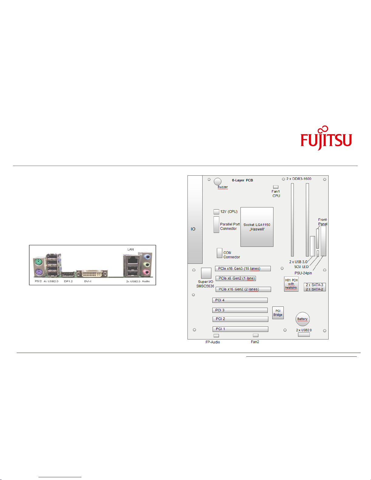
2.2 Basic Layout D3235-S
Page 13
a
Feature Overview
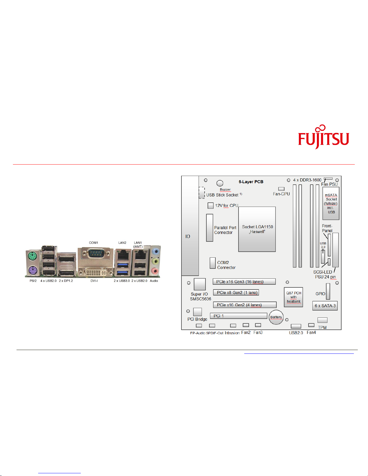
2.3 Basic Layout D3236-S
Page 14
a
Feature Overview
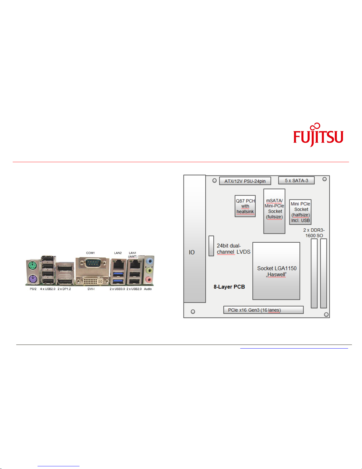
2.4 Basic Layout D3243-S
Page 15

a
Feature Overview
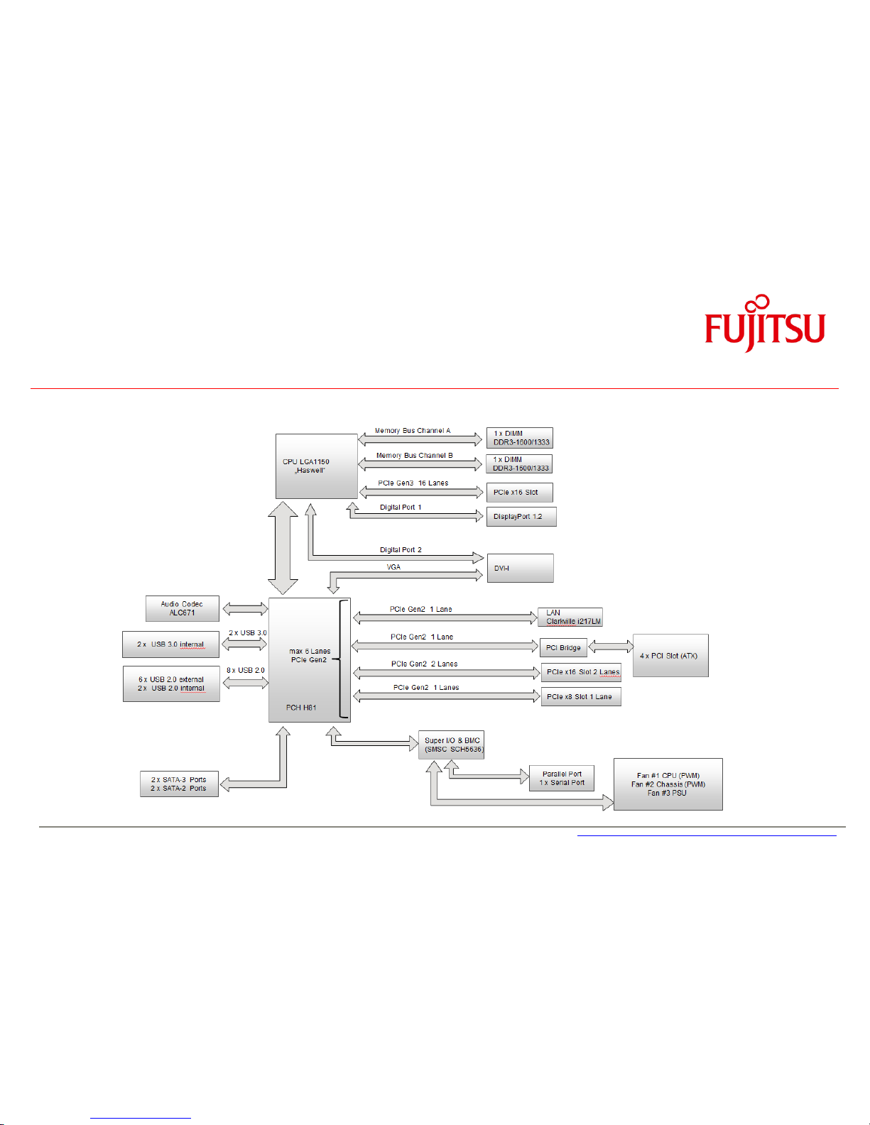
2.5 Block Diagram D3231-S & D3236-S
Page 16
a
Feature Overview
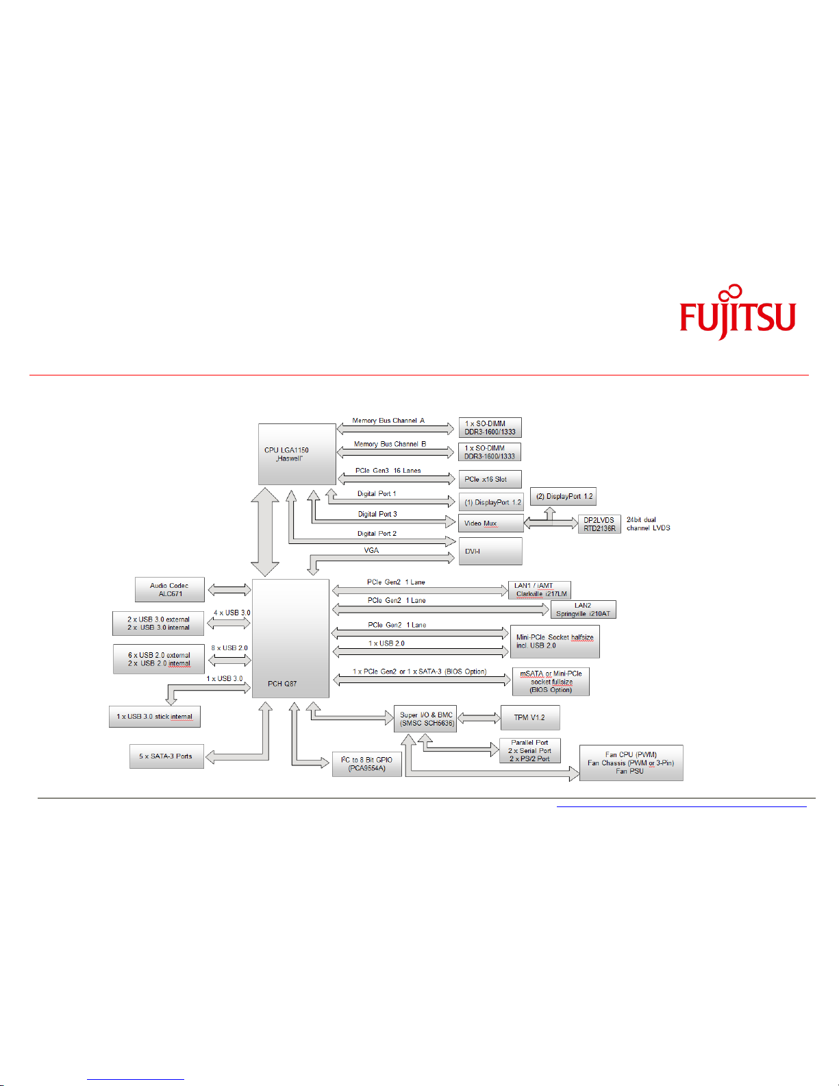
2.6 Block Diagram D3235-S
Page 17
a
Feature Overview
2.7 Block Diagram D3243-S
Page 18
a
Feature Overview
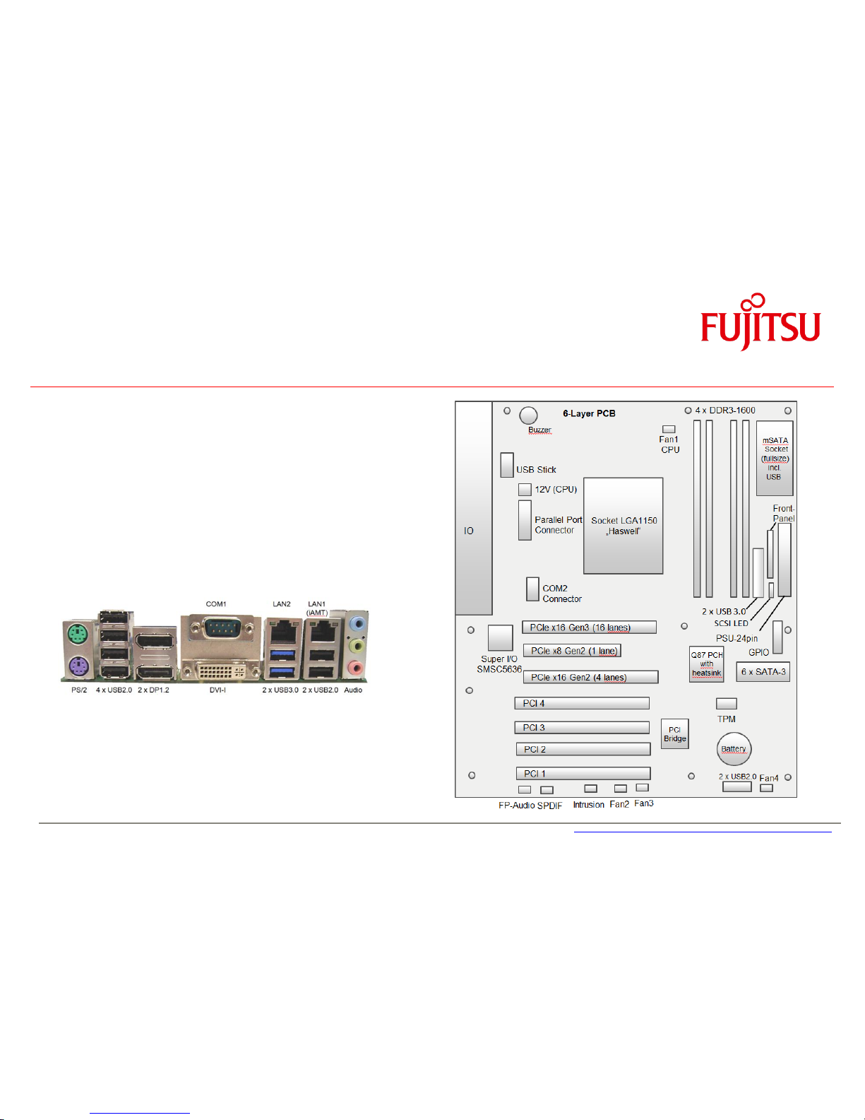
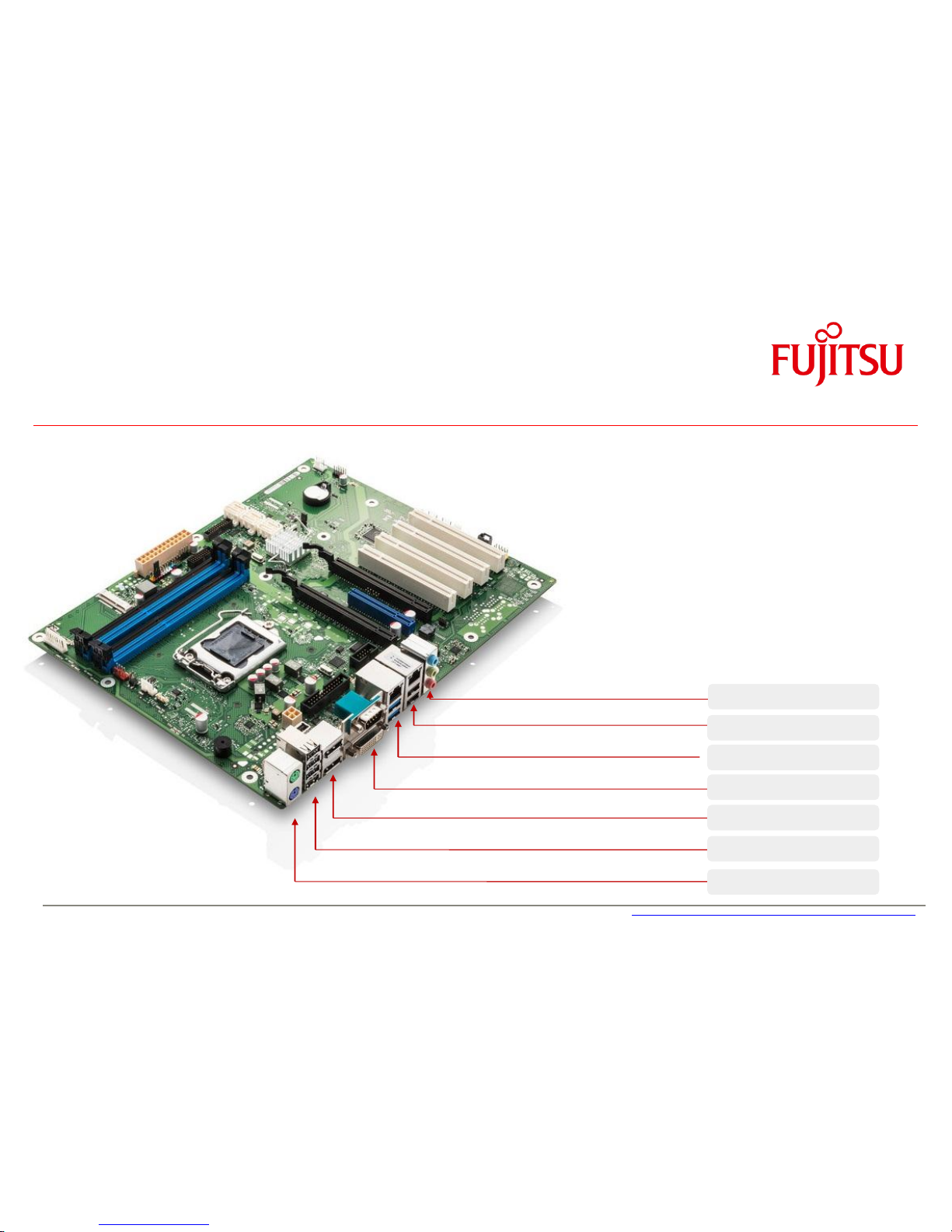
2.8 External Connectors D3231-S / D3236-S & D3243-S
PS/2 Kbd / Mouse
4 x USB 2.0
Dual DisplayPort V1.2
COM1; DVI-I
LAN2 / 2 x USB 3.0
LAN1 (iAMT) / 2 x USB2.0
Audio
Page 19
a
Feature Overview
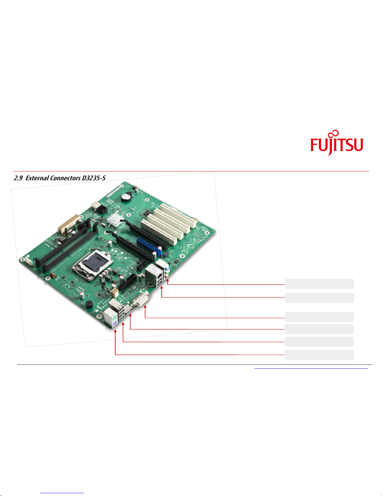
2.9 External Connectors D3235-S
PS/2 Kbd / Mouse
4 x USB 2.0
DisplayPort V1.2
DVI-I
LAN1 / 2 x USB2.0
Audio
Page 20
a
Feature Overview
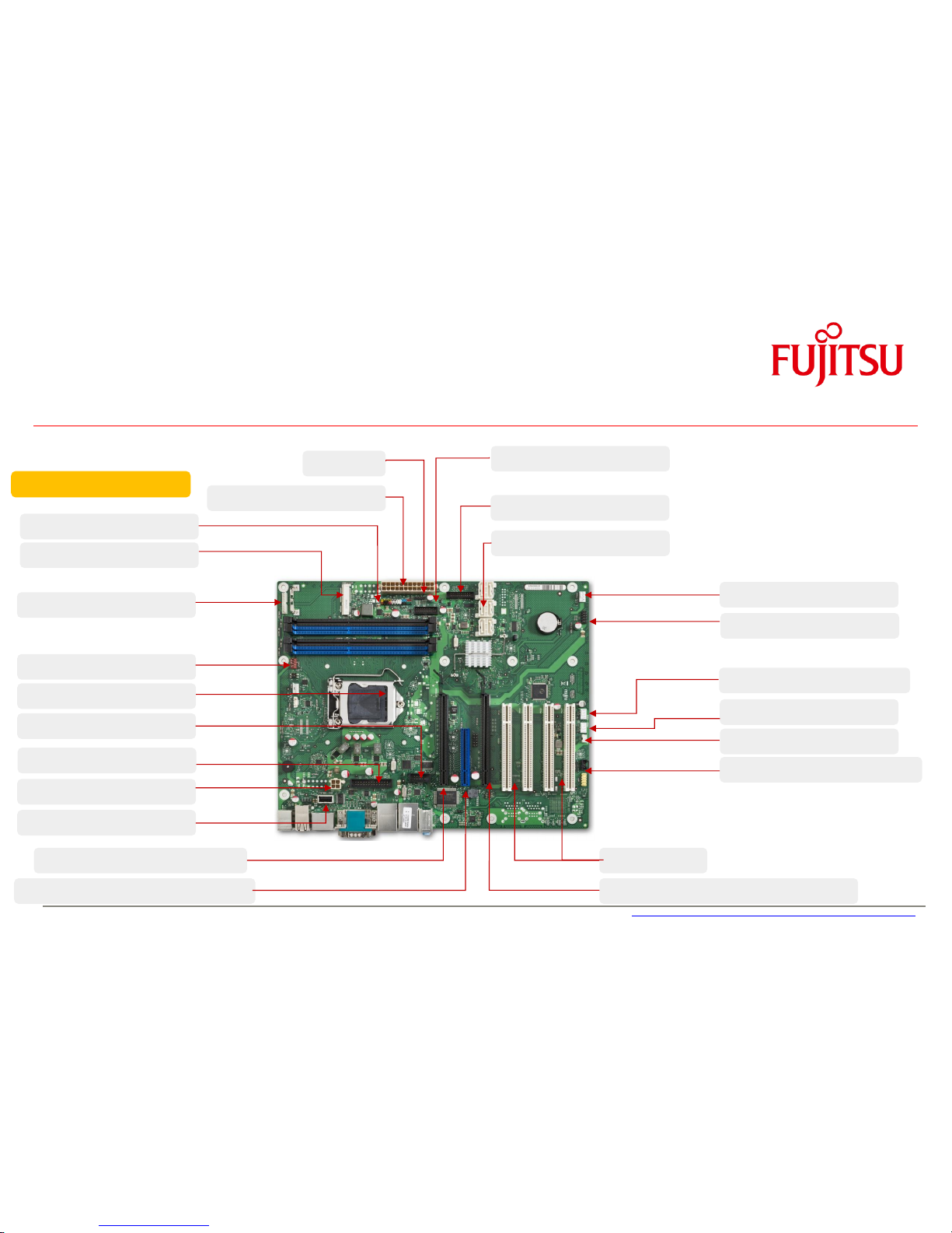
2.10 Onboard components D323x-S
Frontpanel
mSATA Socket
2)
Processor Fan (4 pin)
12V Supply (Processor)
PCIe x16 (16 Lanes, Gen2/3)
PCIe x8 (1 Lane, Gen2, open slot)
24 pin ATX PS
Up to 6 x SATA III
2x USB 3.0 (Frontpanel)
Fan2 (4 pin PWM)
2 x USB 2.0 (Internal)
Intrusion 2)
Frontpanel Audio & S/PDIF 2)
6 Layer PCB
Up to 4 x PCI
1 x PCIe x16 (4 lanes/2lanes, Gen2)
Processor LGA1150
COM Port
8 Bit GPIO 2)
USB 2.0 Socket (Stick) 2)
Fan 4 (4 pin PWM)
1)2)
Fan3 (4 pin PWM / 3 pin) 2)
Parallel Port
1) PSU fan and FAN4 shared!
(BIOS Setup Option)
2) Not available on D3235-S
PSU Fan Control
1)
SCSI LED
Page 21
a
Feature Overview
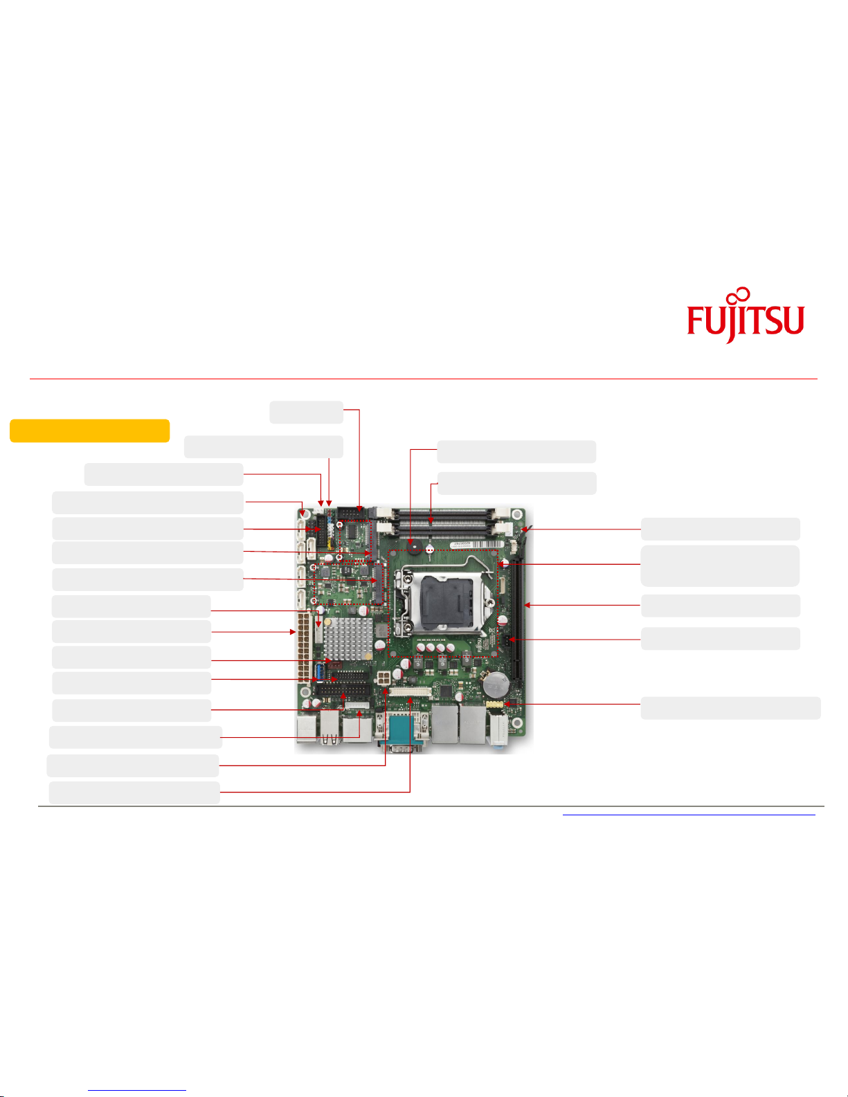
2.11 Onboard components D3243-S
Intrusion
mSATA / Mini-PCIe Socket
Processor Fan (4 pin)
12V Supply (Processor)
LVDS Backlight
LVDS 24bit dual channel
2 x DDR3-1600 SO
S/P-DIF
PCIe x16 Gen3
Frontpanel Audio
8 Layer PCB
PowerSupply ATX/12V
USB3 Stick / GPIO-Port
Buzzer
PSU Fan Control
Fan3 (4 pin PWM / 3 pin)
Parallel Port
COM2
Mini-PCIe Socket (halfsize)
2 x USB2.0 / 2 x USB3.0
5 x SATA-3
Frontpanel
Mounting Area for
LGA1150Heatsink
Page 22

a
Feature Overview
2.12 Summary: Feature Differences D323x-S
Feature
D3231-S
D3236-S
D3235-S
D3243-S
Chipset (PCH)
Q87
Q87
H81
Q87
Memory Sockets / max. RAM
4 / 32GB
4 / 32GB
2 / 16GB
2 / 16GB
PCIe x16 (PEG Slot) [Note: Lane splitting not possible!]
Gen3
Gen3
Gen2
Gen3
PCIe x16- 16 lanes / PCIe x16- 4 lanes/ PCIe x16- 2 lanes /
PCIe x8- 1 lane / PCI
1 / 1 / -- / 1 / 1
1 / 1 / -- / 1 / 4
1 / -- / 1 / 1 / 4
1 / -- / -- / -- / --
mSATA Socket / Mini-PCIe Socket / 8 Bit GPIO / TPM V1.2
x / -- / x / x
x / -- / x / x
-- / -- / -- / --
x3) / x / x / x
USB2.0 Ports internal / external
41) / 6
41) / 6
2 / 6
32) / 6
USB3.0 Ports internal / external
2 / 2
2 / 2
2 / --
32) / 2
Supported Fans / PowerSupply Fan Control
4 / x
4 / x
2 / x
2 / x
SATA2 / SATA3
-- / 6
-- / 6
3 / 2
-- / 5
S-PDIF / Intrusion / SCSI LED
x / x / x
x / x / x
-- / -- / x
x / x / --
COM-Port external / COM-Port internal / Parallel Port internal
1 / 1 / 1
1 / 1 / 1
-- / 1 / 1
1 / 1 / 1
DVI-I / DisplayPort 1 / DisplayPort 2 / LVDS
x / x / x / --
x / x / x / --
x / x / -- / --
x / x / x / x
Dual LAN / Intel iAMT 9.1 - vPro 2014 Manageability
x / x
x / x
-- / --
x / x
BIOS-POST / BIOS-Boot / OS – HW Watchdog onboard
x / x / x
x / x / x x / x / x
x / x / x
EraseDisk (BIOS Feature) included
x x x
x
1) Therof two ports used for USB stick (dongle) and mSATA socket 2) Thereof 1x USB3.0 for USB stick (dongle) and 1 x USB 2.0 for Mini-PCIe
3). Fullsize slot switchable between mSATA or Mini-PCIe (BIOS Option)
Page 23
a
Feature Overview
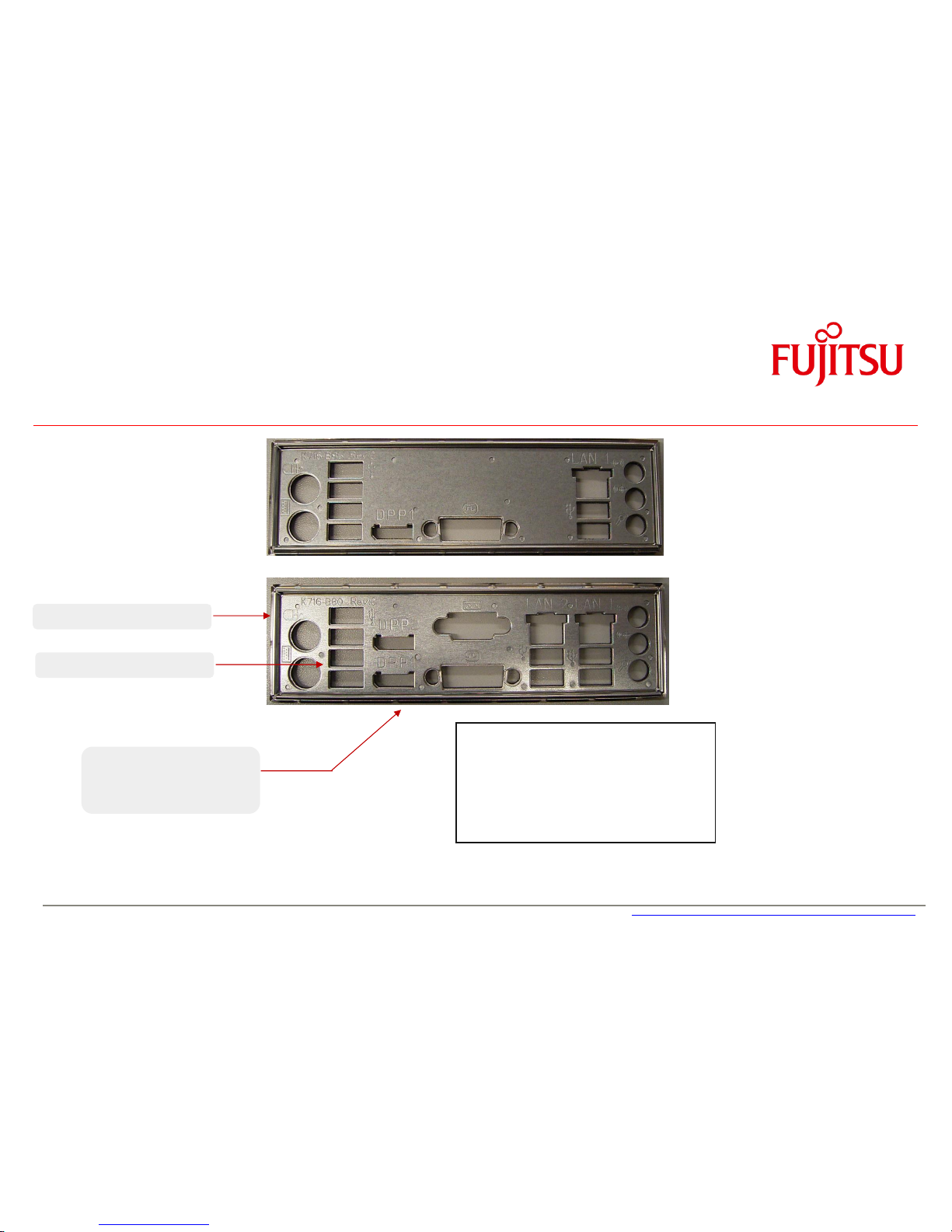
2.13 I/O-Shield
Spring Steel Sheet
Enforcement Sheet
D3235-S
Rear Side: EMI Gasket
(Foam with Copper Nickel
fabric)
Nominal force: ~ 75 N
for specified ATX IO “letterbox”
Note: ATX Chassis “letterbox” for I/O shield:
Nom. size = 158.75 x 44.45mm
Tolerance = +/- 0.2mm
D3231-S
D3236-S
D3243-S
Page 24
a
3 Interfaces & Connectors
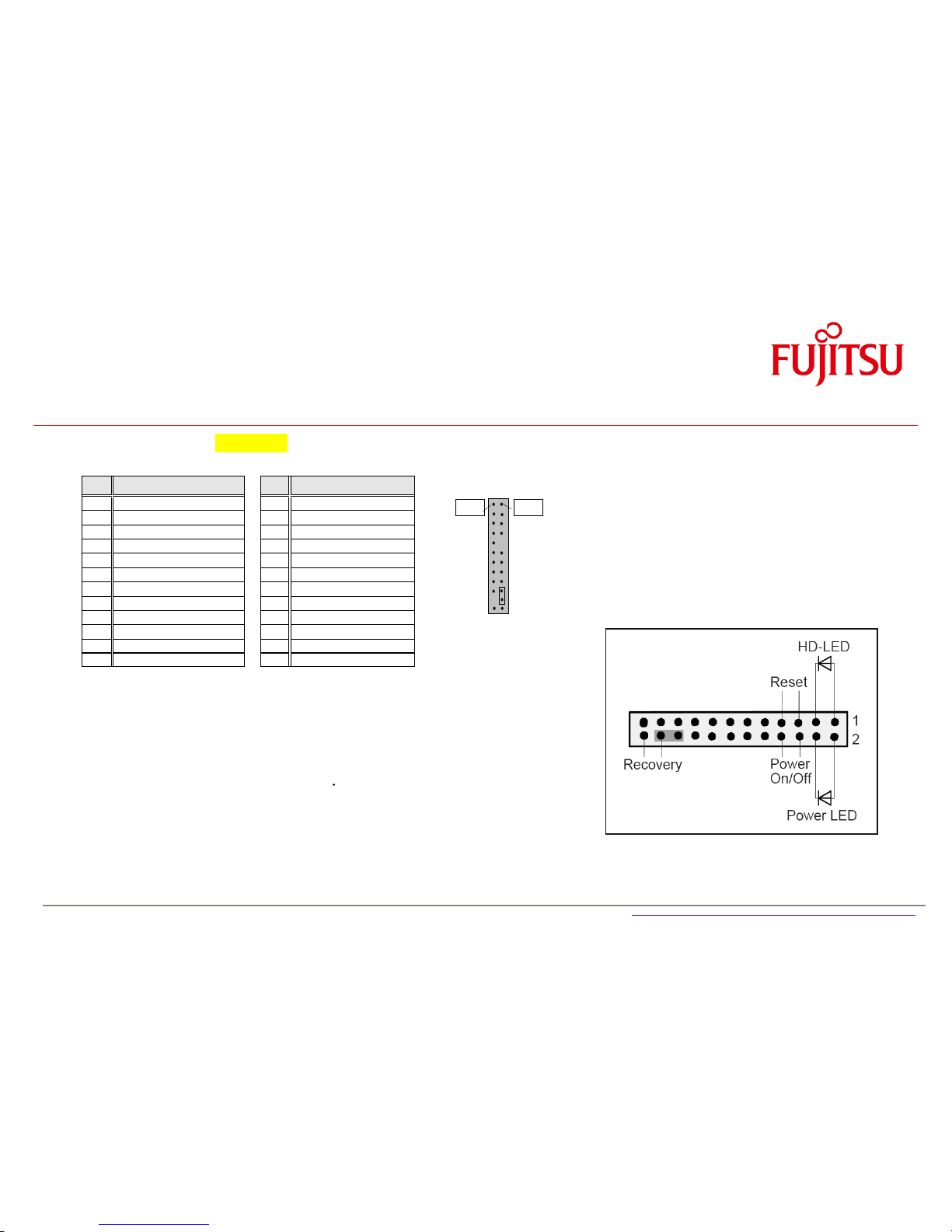
3.1 Frontpanel Connector [Updated]
Pin
Signal
Pin
Signal
1
HD-LED +
2 Power LED +
3
HD-LED -
4 Power LED -
5
GND 6
Power_Button
7
RST_L
8 GND
9
reserved
10
Key
11
reserved
12
GND
13
BMC Alert LED1 +
14
BMC Alert LED1 -
15
reserved
16
reserved
17
Speaker +
18
BIOS Testmode (reserved)
19
GND 20
GND (0,1K)
21
Key 22
GND (0,1K)
23
Speaker -
24
Recover BIOS
Power LED:
Anode: Pin 2 – current source 3mA up to 4V
Cathode: Pin 4 (suitable for various LED colors)
HDD LED:
Anode: Pin 1 – current source 3mA up to 4V
Cathode: Pin 3 (suitable for various LED colors)
Internal Speaker Output:
Differential audio signal; mono, max. 2W RMS / 4Ohm
Note: System Beeps are audible via the internal speaker output only,
even if a device is connected to the external audio ports (rear/front) .
Pin 2
Pin 1
Page 25
a
Interfaces & Connectors
3.2 Internal Serial (COM) Port Connector
Note: D3235-S: The internal COM-Port is COM1
D3231-S / D3236-S / D3243-S: The internal COM-Port is COM2
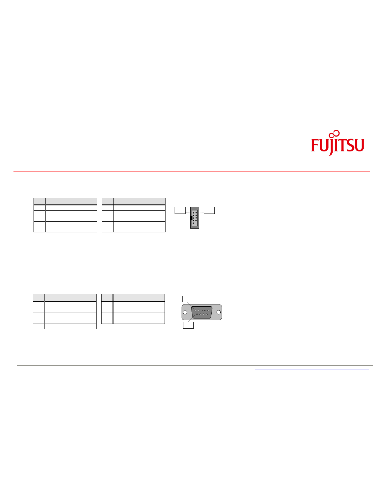
3.3 External Serial (COM) Port Connector
Pin
Signal
Pin
Signal
1
DCD 1
6 DSR 1 2 SIN 1 7
RTS 1
3
SOUT 1
8 CTS 1 4 DTR 1 9
RI 1
5
GND
Pin
Signal
Pin
Signal
1
DCD 2
2 DSR 2 3 SIN 2 4
RTS 2
5
SOUT 2
6 CTS 2 7 DTR 2 8
RI 2
9
GND 10
Key
Pin 1
Pin 2
Pin 1
Pin 6
Page 26
a
Interfaces & Connectors
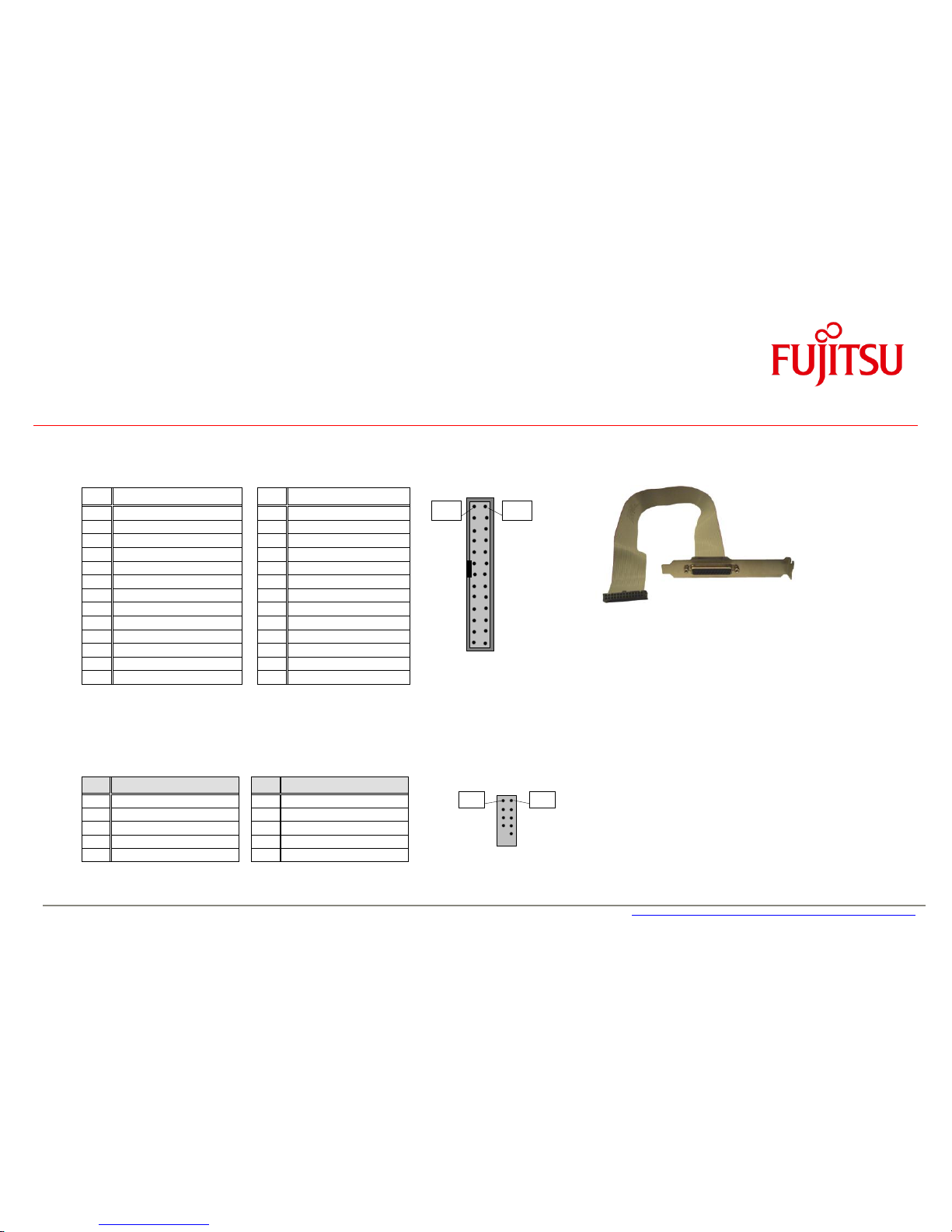
3.4 Internal Parallel Port Connector
Pin
Signal
Pin
Signal
1
Strobe 2
AutoFD
3
Data0 4
Error 5 Data1 6
Init 7 Data2 8
Sel_L
9
Data3 10
GND
11
Data4 12
GND
13
Data5 14
GND
15
Data6 16
GND
17
Data7 18
GND
19
ACK 20
GND
21
Busy 22
GND
23
Empty 24
GND
25
Select 26
GND
3.5 Internal USB2.0 Connector (2 Ports)
Pin
Signal
Pin
Signal
1
VCC AUX
2 VCC AUX
3
Data negative Port X
4 Data negative Port Y
5
Data positive Port X
6 Data positive Port Y
7
GND 8
GND 9 Key 10
Not connected
optional Parallelport cable
with ATX bracket
Pin 2
Pin 1
Pin 1
Pin 2
Page 27
a
Interfaces & Connectors
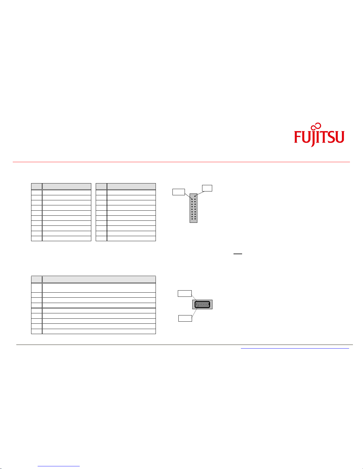
3.6 Internal USB3.0 Connector (2 Ports)
Pin
Signal
Pin
Signal
1
VCC AUX
2 USB3_RX negative (P2)
3
USB3_RX positive (P2)
4 GND
5
USB3_TX negative (P2)
6 USB3_TX positive (P2)
7
GND 8
Data negative (P2) [USB2.0]
9
Data positive (P2) [USB2.0]
10
FP Detect
11
Data positive (P3) [USB2.0]
12
Data negative (P3) [USB2.0]
13
GND 14
USB3_TX positive (P3)
15
USB3_TX negative (P3)
16
GND
17
USB3_RX positive (P3)
18
USB3_RX negative (P3)
19
VCC AUX
Note: All USB3 connectors provide separate signal
lines for USB3.0 and USB2.0!
3.7 External USB3.0 Connector
Pin
Signal
1
VCC auxiliary
(polyswitch fused and power supervision with over current detection)
2
Data negative [USB2.0]
3
Data positive [USB2.0]
4
GND 5 USB3_RX negative
6
USB3_RX positive
7
GND
8
USB3_TX negative
9
USB3_TX positive
Pin 9
Pin 1
Pin 19
Pin 1
Page 28
a
Interfaces & Connectors
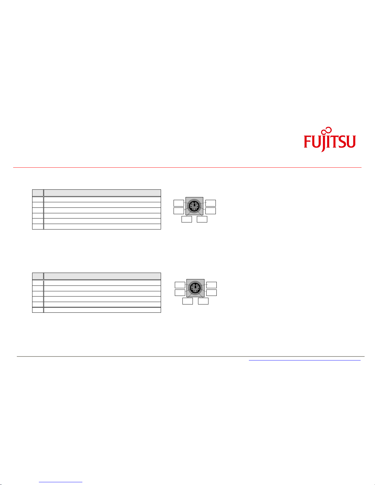
3.8 PS/2 Keyboard Port
Pin
Signal
1
KBD Data
2
Not connected
3
GND 4 VCC (polyswitch fused)
5
KBD CLK
6
Keyboard_On (low asserted pulse)
3.9 PS/2 Mouse Port
Pin
Signal
1
MOUSE Data
2
Not connected
3
GND 4 VCC (polyswitch fused)
5
MOUSE CLK
6
Not connected
Pin 2
Pin 1
Pin 5
Pin 3
Pin 6
Pin 4
Pin 2
Pin 1
Pin 5
Pin 3
Pin 6
Pin 4
Page 29

a
Interfaces & Connectors
3.10 LAN Connector
Pin
Signal with 10/100/1000
Signal with 10/100
1
MX1 +
TX +
2
MX1 -
TX - 3 MX2 +
RX + 4 MX3 +
TERMPLANE
5
MX3 -
TERMPLANE
6
MX2 -
RX - 7 MX4 +
TERMPLANE
8
MX4 -
TERMPLANE
3.11 DVI-I Connector
Pin
Signal
Pin
Signal
1
Data2+
13
NC
2
Data2- 14
Vcc (fused)
3
GND 15
GND
4
NC 16
Hot_Plug_detect
5
NC 17
Data0-
6
DDC_CLK
18
Data0+
7
DDC_DAT
19
GND
8
NC 20
NC 9 Data1- 21
NC
10
Data1+
22
GND
11
GND 23
CLK+
12
NC 24
CLK-
C5
Masse C3
Blue (DVI-I)
C1
Red (DVI-I)
C4
H-Sync (DVI-I)
C2
Green (DVI-I)
Pin 1
C2
C1
C4
C3
C5
Pin 1
Page 30
a
Interfaces & Connectors
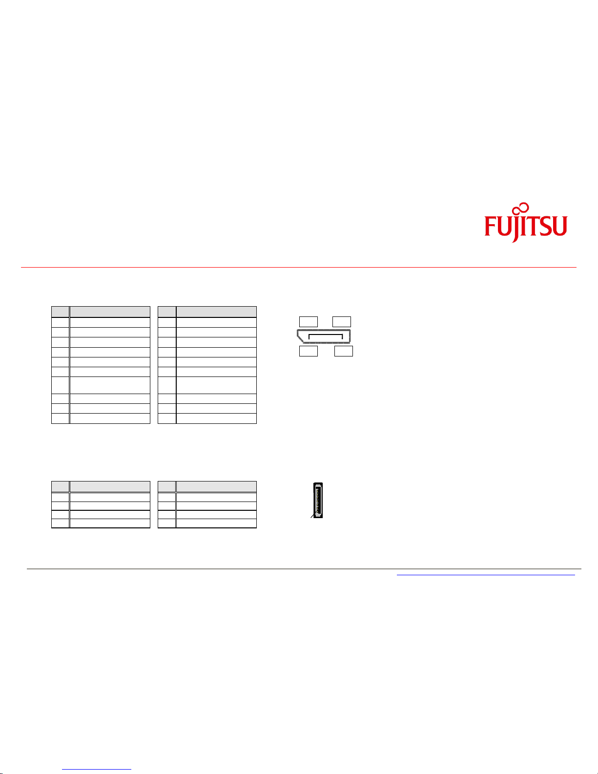
3.12 DisplayPort V1.2 Connector
Pin
Signal
Pin
Signal
1
Link0+
11
GND
2
Link0-
12
Link1+
3
GND
13
Link1-
4
Link2+
14
GND
5
Link2-
15
Link3+
6
GND
16
Link3-
7
DVI dongle detect / (GND
(N/A))
17
GND / (CEC for HDMI
(N/A))
8
AUX+
18
GND
9
AUX-
19
Hotplug detect
10
GND (Return)
20
P3V3P
3.13 Serial ATA Connectors
Pin
Signal
Pin
Signal
1
GND 2
Transmit data positive
3
Transmit data negative
4 GND 5 Receive data negative
6 Receive data positive
7
GND
1
19 2 20
1
Page 31

a
Interfaces & Connectors
3.14
mSATA Pinout / Mini-PCIe Pinout [Updated]
1) Fullsize socket can be used for mSATA
or Mini-PCIe (selectable via BIOS Setup)
2) USB 2.0 for mSATA socket selectable
via BIOS Setup.
Note: If USB 2.0 is enabled for the fullsize
socket, USB 2.0 is no longer available
for the onboard USB 3.0 stick socket!
NC = pin not connected to mainboard
Reserved = pin connected to mainboard
Pin
Signal Assignment
Pin
Signal Assignment
mSATA/Mini-PCIe 1)
Mini PCIe halfsize
mSATA/Mini-PCIe 1)
Mini PCIe halfsize
1
NC / WAKE#
WAKE#
27
GND
2
+3.3V / +3.3V STBY
+3.3V STBY
28
+1.5V
3
NC
29
GND
4
GND
30
NC
5
NC
31
SATA RX- / PCIe RX-
PCIe RX-
6
+1.5V
32
NC
7
NC
33
SATA RX+ / PCIe RX+
PCIe RX+
8
NC
34
GND
9
GND
35
GND
10
NC
36
USB Data - 1)
USB Data -
11
Reserved / REFCLK-
REFCLK-
37
GND
12
NC
38
USB Data + 1)
USB Data +
13
Reserved / REFCLK+
REFCLK+
39
+3.3V / +3.3V standby
+3.3V standby
14
NC
40
GND
15
GND
41
+3.3V / +3.3V standby
+3.3V standby
16
Reserved
42
NC
17
NC
43
GND
18
GND
44
NC
19
NC
45
NC
20
Reserved / EN_WLAN
EN_WLAN
46
NC
21
GND
47
NC
22
NC / PERST#
PERST#
48
+1.5V
23
SATA TX+ / PCIe TX-
PCIe TX-
49
NC
24
+3.3V / +3.3V STBY
+3.3V STBY
50
GND
25
SATA TX- / PCIe TX+
PCIe TX+
51
MSATA Present low
NC
26
GND
52
+3.3V / +3.3V standby
+3.3V STBY standby
Page 32

a
Interfaces & Connectors
3.15
mSATA / Mini-PCIe BIOS Setup Options [New]
The halfsize socket always supports
Mini-PCI Express AND USB 2.0.
It can NOT be used for mSATA modules!
The fullsize socket can be configured
for mSATA modules OR Mini-PCI Express
(BIOS Setup option; default = mSATA).
USB2.0 support for the fullsize socket
can be enabled if needed.
(BIOS Setup option, default = disabled).
Note: If USB2.0 is enabled, the onboard USB stick
socket supports USB3.0 only, but no longer
USB2.0
Mode switch for fullsize socket
USB2.0 switch for fullsize socket
Note: BIOS Setup option “WLAN”
This option can be used to enable/disable Mini-PCIe WLAN modules of D3243-S.
Page 33

a
Interfaces & Connectors
3.16 Fan Connectors
Pin
Signal
1
GND
2
12V 3 FAN Sense
4
FAN PWM
Fan speed control is supported for 4 pin (PWM) fans.
Fan3 can be changed from 4-pin mode to 3-pin controlled mode via BIOS Setup.
3-pin fans (voltage controlled) connected to Fan1/Fan2/Fan4 connector will always operate at full speed resp. 12V supply voltage!
Fan current: max. 2A continuous / 4A peak (D323x-S)
max. 1.5A continuous / 3A peak (D3243-S)
3.17 Power Supply Fan Connector
Pin
Signal
1
Not connected
2
PS Fan PWM
3
Not connected
4
PS FAN Sense
5
Not connected
6
Not connected
7
Not connected
8
GND
Note: This feature is not supported by standard ATX power supplies!
The power supply fan connector is shared with FAN4 connector on D3231-S/D3236-S (BIOS Setup option), they must not be used simultaneously!
Note:
Fans must never be attached or
removed while the system is
powered. Mainboard may be
damaged!
Pin 1
Pin 1
Page 34

a
Interfaces & Connectors
3.18 Rear Audio / Frontpanel Audio Connector [Updated]
Frontpanel Audio: High Definition Mode
Frontpanel Audio: Legacy Mode (AC97)
Note: In case of using this connector in AC97 = Legacy mode (BIOS Setting) take care for pin 7.
This pin is tied to GND. HP_ON# signaling on this pin is not supported.
Pin
Signal
Pin
Signal
1
HDA Port 1 Left
2 Analog GND
3
HDA Port 1 Right
4 FP Presence Detect
5
HDA Port 2 Left
6 Jack Sense Port 1
7
Jack Sense common
8 Key 9 HDA Port 2 Right
10
Jack Sense Port 2
Pin
Signal
Pin
Signal
1
Mic Left
2 Analog GND
3
Mic Right
4 reserved
5
Headphone out Right
6 reserved
7
Analog GND
8 Key
9
Headphone out Left
10
reserved
Note: Front audio operating
mode (High Definition Audio
or Legacy Audio) selectable in
BIOS Setup
Page 35

a
Interfaces & Connectors
Rear Audio / Frontpanel Audio Connector [New]
Rear Audio Connectors
Pin
Signal
A
Line input
Pin
Signal
A
Headphone output
Pin
Signal
A
Microphone input
Electrical input characteristics
Line: Stereo max. 1,2Vrms (Gain=0dB) input voltage
Microphone: Supports electret microphones with 1,3V
rms
(Gain=0dB) or 0,13V
rms
(Gain=20dB)
Electrical output characteristics
Headphone: Stereo max. 1,2 Vrms output voltage at 32Ohm load
System Speaker (via frontpanel connector): Mono, typ. 2W (RMS) at 4Ohm load
Mute Topology
When an outPut device (HeadPhone, HifiAmp...) is attached to an output jack, the following mute topology is required:
FrontOut mutes RearOut and MonoOut RearOut mutes MonoOut (frontpanel system speaker)
Remark: System beeps are only audible via the internal (frontpanel) system speaker. System beeps are also audible on the internal speaker if an external
device is plugged in.
Line IN (light blue)
Pin A
Headphone OUT (lime)
Pin A
Microphone IN (pink)
Pin A
Page 36

a
Interfaces & Connectors
3.19 S/PDIF Connector
Note:
Standard connector bracket should directly
connect to SPDIF out and GND pins
(no signal converter required)
(Sample S/PDIF connector bracket)
Pin
Signal
1
VCC 2 SPDIF out
3
GND
Pin 1
Page 37

a
Interfaces & Connectors
3.20 GPIO (Feature Connector)
Feature Connector: CompuPack R-DRK2-20-S3-SMT
1
GPI/O_0
GPI/O_1
2 3 GPI/O_2
GPI/O_3
4
5
GPI/O_4
GPI/O_5
6
7
GPI/O_6
GPI/O_7
8 9 VCC_3.3V
GND
10
11
VCC_3.3V
VCC_5Vaux
12
13
reserved
GND
14
15
reserved
GND
16
17
GND
VCC_5V
18
19
VCC_12V
VCC_12V
20
Note: Current max. 1.5 A per power pin!
Parameter
Range
GPI/O Input Low Voltage
-0.5V … 0.8V
GPI/O Input High Voltage
2V … 3.3V
GPI/O Output Low Voltage
max. 0.7V
GPI/O Output High Voltage
min. 2.5V
Note: max. load per GPI/O pin: 10mA
(overall current for all GPI/O pins must be < 85mA)
Each GPI/O pin has an integrated serial resistor of 150 Ohm
GPIO access is provided via the SM-Bus controller PCA9554A
ftp://ftp.ts.fujitsu.com/pub/Mainboard-OEM-Sales/Products/Mainboards/Industrial&ExtendedLifetime/
D323x-S/Documentation/Specifiations/GPIO_Chip_PCA9554a.pdf
Note: SM-Bus address: 0x78h (8-bit)
For Windows OS, the FTS BMC API provides easy access to the GPIO:
ftp://ftp.ts.fujitsu.com/pub/Mainboard-OEM-Sales/Products/Mainboards/Industrial&ExtendedLifetime/
D323x-S/IndustrialTools_D323x-S/BMC_Management-Controller-API/
2
1
(Connector location shown for D3231-S/D3236-S)
Page 38

a
Interfaces & Connectors
3.21 Power Supply Connector D323x-S (Multirail)
Pin
Signal
Pin
Signal
13
+ 3.3V (P3V3P)
1 + 3.3V (P3V3P)
14
- 12V (P12VN)
2 + 3.3V (P3V3P)
15
GND 3
GND
16
PS on (low asserted)
4 + 5V (VCC)
17
GND 5
GND
18
GND 6
+ 5V (VCC)
19
GND 7
GND
20
NC 8
Powergood (high asserted)
21
+ 5V (VCC)
9 + 5V Auxiliary (VCC Aux)
22
+ 5V (VCC)
10
+ 12V (P12VP)
23
+ 5V (VCC)
11
+ 12V (P12VP)
24
GND 12
+ 3.3V (P3V3P)
3.22 Additional Power Supply Connector D323x-S (12V for Processor)
Pin
Signal
Pin
Signal
3
+ 12V 1
GND 4 + 12V 2
GND
Pin 13
Pin 1
Pin 3
Page 39

a
Interfaces & Connectors
3.23 Power Supply Connectors D3243-S (ATX Multirail or Single 12V Operation) [Updated]
3.23.1
D3243-S ATX Multirail Operation [Updated]
(24 pin ATX connector)
(4 pin 12V connector for CPU power)
24 pin ATX connector:
* Pin 3 (GND) must be connected (= detection of ATX PSU)
** Pin 14 (-12V) and pin 20 (-5V) are not required for D3243-S
Important Note:
If the Power Supply is changed from
Multirail to single 12V or vice versa, make
sure to disconnect the mainboard D3243-S
from any power at least for 10 minutes!
Page 40

a
Interfaces & Connectors
3.23.2
D3243-S Single 12V Operation [Updated]
(24 pin ATX connector)
(4 pin 12V connector for CPU power)
For single 12V operation both connectors 24 pin and 4 pin are required!
24 pin ATX connector:
* Pin 3, 8, 14, 16 (NC) must NOT be used in single 12V mode!
Important Note (Single 12V mode):
The “output” pins (3.3V
out
, 5V
out
, 12V
out
)
provide power for drives or extra devices.
Maximum “output” power ratings:
+3.3V
out
: max. 4A
= combined output current of 3.3V
PCIe x16 and 3.3V
out
pins (1, 2, 12, 13)
+5V
out
: max. 9A
= combined output current of all USB
ports and +5V
out
pins (4, 6, 21, 22, 23)
+12V
out
: max. 6A
depends on output power of single
12V PSU! (12V
out
= pin 20)
Page 41

a
Interfaces & Connectors
3.23.3
D3243-S Single 12V Operation – Min / Max Config [New]
Sample supply cabling for minimum single 12V configuration: Sample supply cabling for maximum single 12V configuration:
e.g. processor up to 45W, no PCIe card installed, no SATA drives e.g. processor > 45W, additional graphics card, several SATA drives
+12V +12V
GND GND
(Single 12V PSU) (Single 12V PSU)
Note: Each single pin of both connectors is capable of max. 8A!
For processor ≥ 65W all pins of the 4-pin connector must
be used due to peak current in Turbo Mode.
At least pin 9 & 10 or 9 & 11
must be connected to the
+12V supply source!
GND = any GND pin connected
to the supply source.
All five +12Vin pins must be
connected to the +12V supply
source.
Both GND pins (4-pin conn.) &
any three GND pins (24-pin
connector) must be connected
to the supply source.
Page 42

a
Interfaces & Connectors
3.24 Chassis Intrusion [Updated]
Pin
Signal
1
GND
2
Case open (low asserted)
3
Intrusion switch present (low asserted)
Note:
The intrusion supervision feature needs to be enabled in BIOS Setup first (Menu „Security“ „Cabinet
Monitoring“).
This BIOS option is only available if pin 3 („Intrusion Switch Present“) is connected to GND!
Note:
Chassis intrusion is active even if the system is switched off (S5 state) or
disconnected from mains power.
The intrusion event is monitored by the chipset (PCH) and stored in the BIOS
Eventlog during the next Boot.
A timestamp (Boot date/time) will be added then.
Note: This timestamp does not represent date/time of the intrusion event!
If a Supervisor Password is enabled in BIOS Setup, the system will stop
during BIOS POST if an intrusion event has been detected. In order to
continue, the Supervisor Password must be entered to confirm the intrusion
event.
The intrusion status can be easily monitored by using the BMCAPI (Windows):
ftp://ftp.ts.fujitsu.com/pub/Mainboard-OEM-Sales/Products/Mainboards/Industrial&ExtendedLifetime/D323x-S/IndustrialTools_D323x-S/BMC_Management-Controller-API/
Pin 1
Page 43

a
4 System Monitoring
- Temperature Sensors and Fans
- SystemGuard: Fan / Temperature Monitor
- SilentFanConfig-Manager
- Temperature Reference Points
- BMC – BIOS Default Settings
Page 44

a
System Monitoring
4.1 D3236-S / D3231-S: Temperature Sensors and Fan Connectors
PSU Fan Control 3)
Processor
(Fan1; PWM) 1)
Sensor “Memory”
Sensor “CoreRegulator”
Fan 2 (PWM) 1)
Fan 4 (PWM)
1) 3)
Sensor “PCIe Graphics”
Note: Do not attach more than one fan per connector!
Remove or connect fans only when unit is powered off!
Sensor “Super I/O”
Sensor “Processor”
1) 2A continuous / 4A peak current
2) FAN 3:
PWM or 3-Wire
Selectable via BIOS Setup
Default = PWM)
3) FAN 4 / PowerSupply Fan:
Connectors must not be used
simultaneously!
Selectable via BIOS Setup
Sensor “PCH”
Fan 3 (PWM or 3-pin)
1) 2)
Page 45

a
System Monitoring
4.2 D3243-S: Temperature Sensors and Fan Connectors
PSU Fan Control
Processor
(Fan1; PWM) 1)
Sensor “MCard”
Fan 3 (PWM)
1) 2)
Sensor “PCIe Graphics”
Note: Do not attach more than one fan per connector!
Remove or connect fans only when unit is powered off!
Sensor “Super I/O” (SIO)
(rear side below memory)
Sensor “PCH”
1) 1.5A continuous / 3A peak current
2) FAN 3:
PWM or 3-Wire
Selectable via BIOS Setup
Default = PWM)
Sensor “Processor” (PECI)
Sensor “Core Regulator”
(VCore)
Page 46

a
System Monitoring
4.3 D323x-S / D3243-S: SystemGuard
System Monitoring Tool:
• Visualize processor and sensor
temperature data
• Display current speed for all
attached fans
• User can configure fan aging control
(menu “Special”)
• User can configure system watchdog
(menu “Special”)
User can adjust system behaviour via
“Silent PC / Performance PC” slider by
forced processor throttling
Page 47

a
System Monitoring
4.4 D323x-S: SystemGuard - Details
Temperature Sensors
Processor Sensor
1)
Super I/O Sensor
Sensor PCIe Graphics
PCH Sensor
Memory Sensor
Core Voltage Regualtor Sensor
Sensor / Fan Matrix
Indicates which sensor influences the specific fan speed
Note: Characteristics for FAN1 is always dependent on the CPU
temperature – fully controlled by the system BIOS.
Due to safety reasons the influence of the CPU sensor for FAN1
cannot be disabled!
Fan4/PS
Displays the fan speed of the optional power supply fan
(specific PSU option)
1) Note: The temperature value shown for the processor (digital „PECI“ measurement =Platform Environment Control
Interface) does NOT provide the absolute processor temperature, but it is a calculated value based on the relative PECI data.
(Note: Sample screenshot only; data may differ for specific mainboard model)
Page 48

a
System Monitoring
4.5 D3243-S: SystemGuard - Details
Temperature Sensors
Processor Sensor
1)
Super I/O Sensor
Sensor below Mini-PCIe
PCH Sensor
Core Voltage Regulator Sensor
PCI Express x16 Sensor
Sensor / Fan Matrix
Indicates which sensor influences the specific fan speed
Note: Characteristics for FAN1 is always dependent on the CPU
temperature – fully controlled by the system BIOS.
Due to safety reasons the influence of the CPU sensor for FAN1
cannot be disabled!
Note: Fan2 is not available on D3243-S!
Fan4/PS
Displays the fan speed of the optional power supply fan
(specific PSU option)
1) Note: The temperature value shown for the processor (digital „PECI“ measurement =Platform Environment Control
Interface) does NOT provide the absolute processor temperature, but it is a calculated value based on the relative PECI data.
Page 49

a
System Monitoring
4.6 SilentFanConfigManager – Customize System Monitoring Settings
Windows-based System Management Configuration Tool
ftp://ftp.ts.fujitsu.com/pub/Mainboard-OEM-Sales/Products/Mainboards/Industrial&ExtendedLifetime/D323x-S/IndustrialTools_D323x-S/SilentFanConfig-Manager/
1. Windows-based configuration tool (SilentFanConfig) to create customized system monitoring settings like minimum fan speed and
temperature sensor influence. These customized settings are stored in a specific “SMCO” flash file.
2. DOS-based tool “SMCO” to flash the customized system monitoring settings (SMCO file) to the system BIOS of the target unit.
SilentFanConfig-Tool: SMCO-Tool SilentFanConfig-Tool +
Create specific system SMCO Flash File Flash SMCO file to SMCO-Tool =
monitoring settings mainboard BIOS SilentFanConfigManager
(any Windows-based PC) (each unit in production)
Note: New settings are written permanently to system BIOS.
Any BIOS update will not reset the new settings
SilentFanConfig V1.70.1 or higher required for D323x-S, V1.71.0 or higher for D3243-S
Please see documentation in ZIP file (link below) for further details.
ftp://ftp.ts.fujitsu.com/pub/Mainboard-OEM-Sales/Products/Mainboards/Industrial&ExtendedLifetime/D323x-S/IndustrialTools_D323x-S/SilentFanConfig-Manager/
Page 50

a
Capacitor Endurance Time
Solid Electrolyte:
Fluid Electrolyte:
System Monitoring
4.7 Components for continous 24/7 operation @ +60°C
Operating Conditions:
Circulating air
(mainboard) max. 60°C
Usage 24h / 7 days
All onboard electrolyte
capacitors: Polymer type only
(= solid electrolyte)
Lx = effective endurance time
Lo = endurance time @ 105°C
(e.g. 2.000hrs)
to = 105°C
tx = capacitor surface temperature
(e.g. 68°C)
High Efficiency Processor
Core Voltage Regulator
for reduced thermal
dissipation loss
Note: Power Consumption
PCH P max ~ 4.1W
P idle ~ 0.7W
Extra Heatsink
on PCH (Q87)
All voltage regulators =
switching regulators (high
efficiency & stable operation
within full temperature
range). No linear regulators
(low efficiency)
Quartz with enhanced
operating temperature range
COM Driver with enhanced
operating temperature range
6-layer PCB for improved
signal quality within full
operating temperature range
Quartz with enhanced
operating temperature range
Page 51

a
System Monitoring
4.8 Capacitor Endurance Time Comparison
Page 52

a
System Monitoring
4.9 Temperature Reference Points D323x-S
Battery max. 60/70°C 1)
PCH max. 75°C
(chip surface)
All capacitors max. 68°C
Super I/O max. 70°C
Inductors max. 90°C
1) Note: Battery operation is specified in
temperature range up to 60°C. Operation
between 60°C and 70°C may result in:
- Higher self discharge rate
- Decline of specified characteristics
- Danger of leakage increases
Quartz max. 70°C
LAN1/2 max. 75°C
Audio Codec max. 70°C
Reference Point Limit Temperatures (Component Surface) must not be exceeded!
Power MOS-FETs / MOS-FET
Drivers max. 90°C
Operating Conditions:
Circulating air
(mainboard) max. 60°C
Usage 24h / 7 days
PCI Bridge max. 75°C
TPM max. 70°C
Inductor max. 90°C
Quartz max. 70°C
COM Driver max. 70°C
COM Driver max. 70°C
Page 53

a
System Monitoring
4.10 Temperature Reference Points D3243-S (front)
Battery max. 60/70°C 1)
PCH max. 75°C
(chip surface)
All capacitors max. 68°C
Inductors max. 90°C
1) Note: Battery operation is specified in
temperature range up to 60°C. Operation
between 60°C and 70°C may result in:
- Higher self discharge rate
- Decline of specified characteristics
- Danger of leakage increases
LAN i210 max. 75°C
Audio Codec max. 70°C
Reference Point Limit Temperatures (Component Surface) must not be exceeded!
Operating Conditions:
Circulating air
(mainboard) max. 60°C
Usage 24h / 7 days
COM Driver max. 70°C
Inductors max. 90°C
Inductors max. 90°C
VR FETs max. 90°C
Page 54

a
System Monitoring
4.11 Temperature Reference Points D3243x-S (rear)
TPM max. 70°C
Super I/O max. 70°C
LAN i217 max. 75°C
Reference Point Limit Temperatures (Component Surface) must not be exceeded!
Operating Conditions:
Circulating air
(mainboard) max. 60°C
Usage 24h / 7 days
DP Mux max. 85°C
LVDS Converter max. 85°C
COM Driver max. 70°C
Page 55

a
System Monitoring
4.12 BMC – BIOS Default Settings D323x-S
The default system monitoring settings like fan speed, sensor influence, and Alert temperatures are fixed by the system BIOS.
All relevant settings can be customized by system builders via the SilentFanConfig-Manager tool kit.
Sensors
PECI (Processor)
Super I/O
PCIe Graphics
PCH
Memory
Core Regulator
Fan1 (CPU)
X X Fan2
X X X X X Fan3
X X X X X Fan4/PSU
X X X X
X
“X” indicates that this specific sensor influences the speed of this specific fan
StartUp 1)
FullSpeed 2)
Alert 3)
Note
PECI (Processor)
80
99
99
These settings are fixed by the BIOS (depends on the
individual installed processor) and cannot be changed via
SilentFanConfig-Manager.
Super I/O
50°C
65°C
70°C
These settings are implemented for the current
BIOS version and may be changed for upcoming
BIOS versions!
Default minimum fan speed = 30% (all fans).
PCIe Graphics
50°C
65°C
70°C
PCH
55°C
70°C
80°C
Memory
50°C
60°C
65°C
Core Regulator
60°C
75°C
80°C
1) If the sensor temperature is below “StartUp” the fan rotates a its defined minimum fan speed
2) Between “StartUp” and “FullSpeed” the fan speed increases linear
3) If the sensor temperature achieves “Alert”, the system can provide a warning (e.g. via SystemGuard tool)
Page 56

a
System Monitoring
4.13 BMC – BIOS Default Settings D3243-S
The default system monitoring settings like fan speed, sensor influence, and Alert temperatures are fixed by the system BIOS.
All relevant settings can be customized by system builders via the SilentFanConfig-Manager tool kit.
Sensors
PECI (Processor)
Super I/O
MCard
PCH
VCore
Graphics
Fan1 (CPU)
X X Fan2
X X X X X Fan3
X X X X X Fan4/PSU
X X X X
X
“X” indicates that this specific sensor influences the speed of this specific fan
StartUp 1)
FullSpeed 2)
Alert 3)
Note
PECI (Processor)
72
89
89
These settings are fixed by the BIOS (depends on the
individual installed processor) and cannot be changed via
SilentFanConfig-Manager.
Super I/O
50°C
65°C
70°C
These settings are implemented for the current
BIOS version and may be changed for upcoming
BIOS versions!
Default minimum fan speed = 30% (all fans).
MCard
50°C
65°C
70°C
PCH
55°C
70°C
80°C
VCore
60°C
75°C
80°C
Graphics
50°C
65°C
70°C
4) If the sensor temperature is below “StartUp” the fan rotates a its defined minimum fan speed
5) Between “StartUp” and “FullSpeed” the fan speed increases linear
6) If the sensor temperature achieves “Alert”, the system can provide a warning (e.g. via SystemGuard tool)
Page 57

a
5 Power Supply
5.1 ATX Power Supply / Single 12V Supply [Updated]
Connectors for ATX (Multirail) Power Supply
See chapter 3.21 – 3.23 for cabling details!
(1) 24 pin connector (ATX layout)
(2) 4 pin connector (+12V, GND)
Note: The +12V supply (up to 12A) for processor and chipset is provided via the 4 pin
connector! Onboard voltage regulators convert the +12V input power to the appropriate
processor / chipset supply voltages.
(3) Processor Core Voltage Regulator: High Efficiency design for enhanced
power saving and less thermal dissipation loss.
Requirements for ATX Power Supply
for onboard components (worst case incl. processor, memory,
USB devices; w/o PCIe cards, w/o SATA drives)
The ATX power supply must support the minimum load
conditions as mentioned in the left chart.
Single 12V supply only supported by D3243-S!
(3)
(2)
(1)
Page 58

a
6 Display Options
6.1 Summary: Video Output Options D323x-S / D3243-S
Up to three independent displays supported (D3235-S: max. two displays)
Supports Clone Mode, Extended Desktop and Collage Mode (combine 2 or 3 displays to one screen)
Support of 4K display technology via DisplayPort output
Intel Restrictions for simultaneous use of three displays:
o max. 2 x HDMI (via DVI2HDMI or DP2HDMI converter)
o max. 2 x DVI (direct or via DP2DVI converter)
o max. 1 x DVI and 1 x HDMI
o one VGA (analog)
D3243-S: Second DisplayPort can be used as DP or LVDS (via onboard DP2LVDS converter)
D3235-S: Second DisplayPort not available
Page 59

a
Display Options
6.2
VGA
Output
6.3 VGA Output
optional: Audio
VGA via DVI-VGA converter
max. recommended VGA screen resolution:
1920 x 1200
Note: Intel supports “VGA” up to 2048x1536
@75Hz, but signal quality may be limited!
Analog (VGA) Monitor
DVI-I
Page 60

a
Display Options
6.4 DVI Output
max. DVI screen resolution:
1920 x 1200
Note: DVI supports Single Link only!
Digital (DVI) Monitor
DVI
optional:
Audio
Page 61

a
Display Options
6.5 HDMI Output
max. HDMI screen resolution:
1920 x 1200 (Full HD)
HDMI transfers Video & Audio
Digital (HDMI) Monitor
Note: HDMI Audio Device needs to be
enabled via Control Panel!
HDMI
DVI-HDMI Interface
Connector
DVI-I
Page 62

a
Display Options
6.6 DisplayPort Output [Updated]
max. DP screen resolution:
3840 x 2160 @60Hz 1)
(each port)
DisplayPort transfers Video & Audio
1) Important note:
Celeron and Pentium processors support DP
resolutions up to 2560 x 1600 @ 60Hz
(according DP1.1a).
For resolutions up to 3840 x 2160 @ 60Hz
(according to DP1.2) Core i3/i5/i7 processors
are required
Display Port V1.2
Digital (DisplayPort) Monitor
Digital (DisplayPort) Monitor
Page 63

a
Display Options
6.7 Dual Digital plus VGA Output (3 Displays)
DVI-I
DP (or optional DVI via converter cable)
Max. three independent
displays / Extended Desktop
Digital (DVI or DP) Monitor
Digital (DVI or DP) Monitor
Analog (VGA) Monitor
DisplayPortDVI-Converter
Cable (optional)
VGA
DP (or optional DVI via converter cable)
Page 64

a
Display Options
6.8 Three Digital Outputs (3 Displays)
DP (or optional DVI via converter cable)
Digital (DP) Monitor
Digital (DVI or DP) Monitor
Digital (DVI) Monitor
DisplayPortDVI-Converter
Cable (optional)
DVI
DP
Max. three independent displays / Extended
Desktop via onboard outputs
Note:
Internal graphics supports max. two independent DVI displays
Simultaneous use of internal graphics and PCIe graphics is
possible.
Page 65

a
Display Options
6.9 LVDS Display & Backlight Inverter (D3243-S)
Integrated Backlight, powered by Inverter
Backlight
Inverter
Page 66

a
Display Options
6.10 LVDS Connector Details (D3243-S)
PIN SIGNAL SIGNAL PIN
2 Ground Ground 1
4 LVDS_H3+ (EVEN_3+) LVDS_L3+ (ODD_3+) 3
6 LVDS_H3- (EVEN_3-) LVDS_L3- (ODD_3-) 5
8 Ground Ground 7
10 LVDS_H2+ (EVEN_2+) LVDS_L2+ (ODD_2+) 9
12 LVDS_H2- (EVEN_2-) LVDS_L2- (ODD_2-) 11
14 Ground Ground 13
16 LVDS_H1+ (EVEN_1+) LVDS_L1+ (ODD_1+) 15
18 LVDS_H1- (EVEN_1-) LVDS_L1- (ODD_1-) 17
20 Ground Ground 19
22 LVDS_H0+ (EVEN_0+) LVDS_L0+ (ODD_0+) 21
24 LVDS_H0- (EVEN_0-) LVDS_L0- (ODD_0-) 23
26 Ground Ground 25
28 LVDS_CLK_H+ (CLK_EVEN+) LVDS_CLK_L+ (CLK_ODD+) 27
30 LVDS_CLKH- (CLK_EVEN-) LVDS_CLK_L- (CLK_ODD-) 29
32 Ground Ground 31
34 DDC-Data DDC-Clock 33
36
LCD-Power
1)
LCD-Power
1)
35
38 Ground
LCD-Power
1)
37
40 LCD_Power_Enable Ground 39
1) selectable via Jumper
LVDS Connector: Hirose DF13-40 (or compatible)
LVDS operating voltage selector jumper
2.
1.
Note: LVDS pinning is compatible to
D2703-S / D2963-S / D3003-S / D3313-S
40.
39.
Page 67

a
Display Options
6.11 Backlight Inverter Connector Details (D3243-S)
Backlight Inverter Connector: JST PHR-8
Backlight Brightness Control:
Provides a variable DC voltage between 0V and 4V via an RC filter (10kOhm / 20uF; buffered output).
Alternatively a PWM control is available, please see related jumper setting.
Basically the brightness level can be selected by BIOS Setup, but it is also accessible
from Windows OS.
If this control signal is used, the system integrator is responsible for the implementation of a backlight
converter that fits to the control output voltage range.
Backlight On/Off Control:
Active High, 3.3V Note: Polarity can be changed via BIOS Setup
LVDS Backlight Brightness Control Jumper
(Select analog or PWM output)
1. 8.
Page 68

a
Display Options
6.12 LVDS Timing & Screen Resolution (D3243-S)
There are 9 default LVDS settings available
BIOS Setup – Advanced –LVDS Config Select
Note: Option 10 (LVDS adjusted Parameters)
becomes visible after running the “LVDS Tool”
for implementing customized LVDS settings
once.
Important note:
“Non-EDID Support” must be set to
<Enabled> for standard LVDS displays
w/o DDC (EDID) interface!
Page 69

a
Display Options
LVDS Timing & Screen Resolution (D3243-S)
LVDS Mode:
The correct mode must be set for the attached LVDS panel.
Note: This setting is also required if customized LVDS timings are
implemented (LVDS tool)!
LVDS Brightness:
Set the level for the „Backlight Brightness Pin“.
Typical voltage level (analog mode) resp. PWM level:
BIOS-Setting Voltage Level / PWM Level
0 0.1V / 0.4%
255 4.1V / 100%
The LVDS brightness level can be adjusted in BIOS Setup or via
Windows 7 / Windows 8.1 Mobility Center (<Windows key> + <X>)
Page 70

a
Display Options
LVDS Timing & Screen Resolution (D3243-S)
POST Screen Mode:
Default setting = Graphic Mode (800 x 600).
For panels < 800 x 600 mode could be changed to <Text Mode> in
order to enable full BIOS POST screen resp. full BIOS Setup screen
(otherwise some portion of the screen may be cut off)
Page 71

a
Display Options
6.13 LVDS Tool
[Updated]
The LVDS tool (DOS-based) allows to flash specific
LVDS settings to the system BIOS of D3243-S.
The LVDS tool needs a panel-specific
EDID configuration file based on the spec data
of the LVDS panel.
Note: Sample configuration EDID files
are available in the LVDS Tool kit.
For adjusting EDID files the “Phoenix EDID tool”
Is required (see link below).
(Sample screen message after running LVDS tool)
Download-Link for LVDS Tool:
ftp://ftp.ts.fujitsu.com/pub/Mainboard-OEM-Sales/Products/Mainboards/Industrial&ExtendedLifetime/D3243-S/IndustrialTools_D3243/LVDS-Tool/
BIOS ≥ R1.20.0.SR2 and LVDS tool ≥ V2.2.1 must be used to implement customized LVDS settings
Note:
The onboard LVDS converter switches automatically between single channel and dual channel mode.
The reference resolution is 1366 x 800 pixels. If H > 1366 or V > 800, the scaler switches to dual channel mode.
Otherwise, LVDS will operate in single channel mode.
The scaler supports clock rates up to 105Mhz; LVDS displays with clock rates > 105Mhz are not supported
Page 72

a
Display Options
6.14 LVDS – Influence on Graphics Output D3243-S
[New]
When LVDS support is enabled in BIOS Setup of D3243-S, this has some effect on the support of the other graphics output ports (DVI-D, VGA via DVI-I, DisplayPort).
Furthermore, the setting “Secure Boot” (required for Windows 8.1) also influences the supported graphics output modes.
Important note: If Secure Boot is enabled, the System BIOS uses the GOP (Graphics Output Protocol) graphics driver. In addition, there is another BIOS Setup option
available (in Secure Boot mode only!): AMI Graphic Output Protocol Policy.
The settings in this menu should never be changed, otherwise any video outputs may be inaccurate!
Do NOT touch / change these settings!
BIOS Setup option to select Secure Boot:
Disabled for MS Windows 7 (=default)
Enabled for MS Windows 8.1
Additional BIOS Setup graphics option,
available in Secure Boot mode only
Page 73

a
Display Options
LVDS – Influence on Graphics Output D3243-S [New]
The following table shows the supported video ports for Windows OS, BIOS Setup and DOS mode (e.g. DOS USB Stick; DOS not applicable for Secure Boot mode!).
Windows 7 Mode (BIOS Setup Secure Boot Disabled)
Used Video Ports
LVDS
DVI
DP (lower port)
VGA (via DVI dongle)
LVDS & DVI-D
Win7
BIOS Setup
DOS
Win7
BIOS Setup
DOS ---
LVDS & VGA
Win7
BIOS Setup
DOS
Win7
BIOS Setup
DOS ---
LVDS & DP
Win7
BIOS Setup
DOS
Win7
BIOS Setup
DOS ---
LVDS & DVI-D & DP
Win7
BIOS Setup
DOS
Win7
BIOS Setup
DOS ---
Win7
BIOS Setup ---
DOS ---
LVDS & DP & VGA
Win7
BIOS Setup
DOS
Win7
BIOS Setup
DOS ---
Win7
BIOS Setup ---
DOS ---
Windows 8.1 Mode (BIOS Setup Secure Boot Enabled)
Used Video Ports
LVDS
DVI
DP (lower port)
VGA (via DVI dongle)
LVDS & DVI-D
Win8.1
BIOS Setup
Win8.1
BIOS Setup
LVDS & VGA
Win8.1
BIOS Setup
Win8.1
BIOS Setup
LVDS & DP
Win8.1
BIOS Setup
Win8.1
BIOS Setup
LVDS & DVI-D & DP
Win8.1
BIOS Setup
Win8.1
BIOS Setup
Win8.1
BIOS Setup ---
LVDS & DP & VGA
Win8.1
BIOS Setup
Win8.1
BIOS Setup ---
Win8.1
BIOS Setup
Page 74

a
Display Options
6.15 LVDS Cabling Reference
Display Size TFT Pixel Inverter
10.4" NEC NL6448BC33-63D 640 x 480 NEC 104PW201
12.1" AUO G121SN01-V0 800 x 600 Green-C&C GH093A-ROHS
12.1" LG-Philips LB121S03-TL01 800 x 600 Green-C&C GH001HB-ROHS
15" Sharp LQ150X1LW71N 1024 x 768 TDK CXA-0349
15" AUO G150XG01V0 1024 x 768 Green-C&C GH001A-ROHS
17" AUO M170EG01-VD 1280 x 1024 Green-C&C GH053A-ROHS
19" Sharp LQ190E1LW01 1280 x 1024 Power Systems PS-DA0412-05
19" AUO M190EG01 1280 x 1024 GH053(A1)-ROHS
Sample cabling diagrams for following LVDS displays & related inverters are available:
ftp://ftp.ts.fujitsu.com/pub/Mainboard-OEM-Sales/Products/Mainboards/Industrial&ExtendedLifetime/D3243-S/Documentation/LVDS_Cabling-Samples/
Page 75

a
Display Options
6.16 LVDS Sample Cabling for AuO-G150
Page 76

a
7 Operating System Support
- Windows® 7
- Windows® 8.1
- Linux
Page 77

a
Operating System Support
7.1 Support for Windows 7 / Windows 8.1
• Mainboards D323x-S and D3243-S are designed according to the
Microsoft Guidelines for Windows 7 and Windows 8.1
• MS certified drivers are available via OEM DU-DVD
and OEM FTP Server
ftp://ftp.ts.fujitsu.com/pub/Mainboard-OEM-Sales/Products/Mainboards/Industrial&ExtendedLifetime/D323x-S/Drivers_D323x-S/
Note: D323x-S and D3243-S use the same “family drivers”
Page 78

a
Operating System Support
7.2 Linux Support [Updated]
Ubuntu Desktop 13.10
Ubuntu LTS 12.04.3
Fedora 19.1
SUSE SLES 11 SP3 64bit
OpenSUSE 13.1
„flickering screen“ after installation; solved after update
Debian 7.2.0
Network driver issue Debian kernel “too old” for LynxPoint system
Note: Hints regarding usage of Watchdog, GPIO, LM-Sensors:
ftp://ftp.ts.fujitsu.com/pub/Mainboard-OEM-Sales/Products/Mainboards/Industrial&ExtendedLifetime/D323x-S/IndustrialTools_D323x-S/Linux_SystemMonitoring&Watchdog&GPIO/
Page 79

a
8 Mainboard Tools
Common Mainboard Tools [Updated]
Note: Make sure to not use any DOS memory manager like
himem.sys
oder
emm386!
8.1 BIOS Boot Logo Tool
- Tool to integrate a customized boot logo
ftp://ftp.ts.fujitsu.com/pub/Mainboard-OEM-Sales/Services/Software&Tools/Common-Mainboard-Tools/BootLogo_4_UEFI/
8.2 EditCMOS
- DOS-based production tool to change BIOS settings
and freeze customized BIOS settings (= customized default settings)
ftp://ftp.ts.fujitsu.com/pub/Mainboard-OEM-Sales/Services/Software&Tools/Common-Mainboard-Tools/EditCMOS_UEFI/
8.3 OEMIDENT
- Production tool to add MS OEM licence data (SLP1 / SLP2.x / OA3.0)
- Add an individual customer serial no / add a chassis asset tag and patch several DMI data
- Disable and hide TPM feature in BIOS Setup
ftp://ftp.ts.fujitsu.com/pub/Mainboard-OEM-Sales/Services/Software&Tools/Common-Mainboard-Tools/OEM-Ident/
Page 80

a
Mainboard Tools
8.4 SystemGuard
- Windows-based tool to monitor temperatures and fan speed of FTS mainboards
- Option to configure automatic fan ageing supervision
- Provides access to the System Watchdog
ftp://ftp.ts.fujitsu.com/pub/Mainboard-OEM-Sales/Services/Software&Tools/Common-Mainboard-Tools/SystemGuard/
Note: SystemGuard V4.04 (or higher) recommended for D323x-S and D3243-S
Page 81

a
Mainboard Tools
Industrial Tools
8.5 SilentFanConfig-Manager
- Windows-based configuration tool to implement customized fan
characteristics and temperature parameters. Includes DOS-based
tool "SMCO" to flash the configuration file permanently into the system BIOS.
ftp://ftp.ts.fujitsu.com/pub/Mainboard-OEM-Sales/Products/Mainboards/Industrial&ExtendedLifetime/D323x-S/IndustrialTools_D323x-S/SilentFanConfig-Manager/
8.6 LVDS Tool
- Tool to adjust LVDS-timings for mainboard D3243-S. Adjusted data are flashed into the system BIOS permanently.
Download-Link for LVDS Tool:
ftp://ftp.ts.fujitsu.com/pub/Mainboard-OEM-Sales/Products/Mainboards/Industrial&ExtendedLifetime/D3243-S/IndustrialTools_D3243/LVDS-Tool/
See chapter 5 (LVDS section) for more details.
Page 82

a
Mainboard Tools
8.7 Windows System-Monitoring API (BMCAPI)
- BMC-Management-Controller to access and adjust System Monitoring parameters like
fan speed and temperatures. This API also provides access to the mainboard watchdog, the 8Bit GPIO interface and
the intrusion feature of the mainboard.
ftp://ftp.ts.fujitsu.com/pub/Mainboard-OEM-Sales/Products/Mainboards/Industrial&ExtendedLifetime/D323x-S/IndustrialTools_D323x-S/BMC_Management-Controller-API/
8.8 Linux System-Monitoring Driver (“LM-Sensors”)
- BMC-Management-Controller to access and adjust System Monitoring parameters like
fan speed and temperatures. This driver also provides access to the mainboard watchdog.
ftp://ftp.ts.fujitsu.com/pub/Mainboard-OEM-Sales/Products/Mainboards/Industrial&ExtendedLifetime/D323x-S/IndustrialTools_D323x-S/Linux_SystemMonitoring&Watchdog&GPIO/
Note: Further details regarding mainboard tools can be found in the related “Mainboard Tools Datasheet”
ftp://ftp.ts.fujitsu.com/pub/Mainboard-OEM-Sales/Services/Software&Tools/Common-Mainboard-Tools/$$_DS_UEFI-Tools.pdf
Page 83

a
9 Known Issues & Important Notes
9.1 Driver support for MS Windows XP / MS Win8 [Updated]
For the Q87/H81 chipset there are following restrictions (Intel):
- No driver support for Windows XP
Note: Limited XP driver support for embedded applications. Currently under investigation
- Limited driver support for Windows 8 / 32Bit
9.2 Memory Issue
The 2GB module Samsung M378B5773CH0-CK0 may show sporadic issues with D323x
(in particular when 4 modules are installed). These modules should not be used!
Recommended alternative:
Samsung M378B5773DH0-CK0 (= new stepping)
9.3 Possible Power Supply Issue
Please note that the requirements regarding minimum ATX PSU load have been update by Intel due to enhanced sleep states of the Haswell processors.
Please make sure to use only power supplies qualified by Intel or models that comply with the updated specification (main change: min. load @ 12V reduced
to 0.05A – current PSUs may become instable with this low load).
D323x-S and D3243-S provide some additional load (“dynamic load”) during power-on in order to facilitate the use of previous PSU models.
Page 84

a
Known Issues & Important Notes
9.4
SATA Interface (Intel chipset limitation)
D323x and D3243-S may show compatibility issues with SATA-II harddisk drives. Intel strongly recommends to use SATA-III HDDs only.
D323x and D3243-S may show compatibility issues with SATA optical drives (older models). Please make sure to use latest revision of
optical drives and related firmware only.
9.5
SATA / eSATA Signal Quality [New]
Please note:
In BIOS Setup, if “eSATA” mode is enabled for any SATA port, the speed for this port is reduced to SATA Gen2.
The driver strength is NOT influenced by this setting.
9.6
Graphics driver: Support for Collage Mode
In order to use the new Collage Mode (combine several displays to one display) graphics driver “3355” or higher is required
FTP download: ftp://ftp.ts.fujitsu.com/pub/Mainboard-OEM-Sales/Products/Mainboards/Industrial&ExtendedLifetime/D323x-S/Drivers_D323x-S/
9.7
mSATA support
D3231-S and D3236-S provide an mSATA socket. Please note that one SATA channel (Port 2) and mSATA are shared and cannot be used
simultaneously. By default, Port2 is enabled and mSATA disabled. Please select the required option in BIOS Setup accordingly.
Page 85

a
Known Issues & Important Notes
9.8
USB3.0 Performance
A single USB3.0 port supports data transfer rates up to 5Gb/s.
Please note that there may be a bottleneck between PCH and processor,
as the DMI link is shared by all highspeed busses in the system.
Block diagram: High speed busses Q87/H81 system
According to Intel, typically two USB3.0 ports can be used simultaneously (Max. 5Gb/s for each port)
Page 86

a
Known Issues & Important Notes
9.9
Support for Haswell Refresh (HR) Processors [New]
D3243-S: All mass production mainboards are prepared for HR processors
D323x-S:
For HR processors, both BIOS ≥ R1.18.0 and Management Engine (ME) Firmware ≥ V9.1.0.1120 are required.
With older BIOS or ME-Firmware versions Haswell Refresh processors cannot be used (mainboard will not boot!).
Mainboards D323x-S "GS2" and newer are delivered ex factory with BIOS and ME-Firmware ready for HR processors.
For mainboards version D323x-S "GS1" with older BIOS or ME-Firmware please follow the steps below, using any older Haswell (not Haswell Refresh) processor:
First install BIOS R1.18.0 or newer (this prepares the mainboard for the ME firmware update)
(2) Next install BIOS R1.18.0.SR1 ("Service Release BIOS", this installs the ME firmware update)
Note: BIOS upgrade may take some time before indicating any progress! Please be patient.
(3) Optional: Now any BIOS version ≥ R1.18.0 can be installed
Please make sure that the Haswell Refresh processor is NOT installed before steps (1) and (2) are performed.
Additional note – Possible PCIe x16 issue:
After installing a HR processor in mainboard D323x-S (BIOS < R1.21.0), it may happen that the PCIe x16 slot is corrupted (e.g. PCIe graphics card not working). This
behaviour is based on an Intel firmware bug. There is a tool to reset affected mainboards:
ftp://ftp.ts.fujitsu.com/pub/Mainboard-OEM-Sales/Services/Software&Tools/Common-Mainboard-Tools/HaswellRefresh_PCIeX16/
Link to processor compatibility overview (provides overview about Haswell / Haswell Refresh processors):
ftp://ftp.ts.fujitsu.com/pub/Mainboard-OEM-Sales/Services/Compatibility_CPU_x_Board/Compatibility_CPUxBoard.pdf
Page 87

a
Known Issues & Important Notes
9.10
PCI Slots D323x-S [New]
Possible issue: PCI slot of D3231-S does not operate as expected Please install BIOS ≥ R1.18.0
General note: D323x-S support 5V-only and 3.3V/5V universal PCI cards.
Mainboard signal level is 3.3V (=5 V tolerant)
3.3V-only PCI cards can NOT be used (different mechanical connector layout)
Since the current Intel chipsets do not natively support PCI any more, D323x-S use a Pericom
PI7C9X118SL PCIe to PCI Bridge which is compliant to PCI Rev. 2.3 (32Bit/33 MHz).
There are several “older” PCI cards that comply to PCI Rev. 2.1 or earlier only. These cards may NOT be supported on D323x-S.
9.11
PCI Express Slots [New]
Possible options to get critical PCIe cards working:
Reduce PCIe link speed in BIOS Setup
Use BIOS ≥ R1.20.0
Change Link State Power Management setting within Windows OS
Control Panel / Power Options / Change Plan Settings / Change advanced power settings / PCI Express / Link State Power Management
Change from “moderate power savings” or “maximum power savings” to “Off”.
Note: With BIOS 1.20.0.SR1 and later the PCIe power management settings are changed so that the OS cannot re-enable them even
though they are disabled by default in the BIOS.
Page 88

a
Known Issues & Important Notes
9.12
Intel iAMT / vPRO Manageability Support [New]
Mainboards D3231-S, D3236-S and D3243-S featuring the iQ87 chipset provide full support for iAMT / vPro.
Appropriate Core i5 / Core i7 processors: Full iAMT / vPro feature set supported
Some Core i5 / some Core i7 / Core i3 / Pentium: Only “Standard Manageability” supported (e.g. no KVM)
Celeron processors: No Manageability supported
Note: KVM support is only possible via the processor-integrated graphics!
Page 89

a
10 Miscellaneous
10.1 Specific BIOS Modes “Always On” & “Never Off” (D3243-S) [New]
The BIOS Setup of D3243-S provides two settings for specific operating modes
Always On (Power Failure Recovery)
The system is forced to power up under any condition whenever power is connected to the system.
e.g. when mainboard battery is dead
Default setting: “Power Failure Recovery = Always On”
Never Off
The system cannot be switched off by the mainboard power button or from Windows OS.
If any shutdown (incl. S3 / S4) or power button override is detected, the system is forced to powered up and reboot again.
This feature may be used e.g. for unattended systems that should never be shut down.
Default setting: “Never Off = disabled”
Note: If “Never Off = enabled”, then Power Failure
Recovery should be set to “Always On”!
This Never Off-feature is only supported
by mass production mainboards D3243-S!
Page 90

a
Miscellaneous
10.2 Battery Lifetime [New]
The typical battery lifetime is designed for 5 years.
This is based on following usage profile:
G3 28% / two days per week
(System Off, Power disconnected)
Deep S5/S4/S3 48% / 17 hrs per working day
(System Off, Power connected)
S0 24% / 8 hrs per working day
(System Working)
On-Temperature (S0): 70°C
Off-Temperature (G3, S5/S4/S3): 23°C
Note: If the system is never in G3 mode or if the S0 “working” temperature is lower than 70°C, this may result
in much higher battery lifetime.
Page 91

a
Miscellaneous
10.3 Trusted Platform Module (TPM) [Updated]
TPM V1.2 controller: Infineon SLB9635 (D3231-S/D3236-S) resp. Infineon SLB9660 (D3243-S)
TPM Infineon
TPM Jumper
(D3231-S / D3236-S) (D3243-S: TPM located on rear side)
Note:
- TPM Jumper must be installed in order to enable the TPM hardware (installed = default)
- TPM must be enabled in BIOS Setup before its features can be used
- For applications / customers that do not what to use TPM, the full functionality can be disabled and
hidden in BIOS Setup by the OEMIDENT tool. See OEMIDENT readme for details.
Once TPM has been disabled by OEMIDENT, it cannot be re-enabled again (only possible by factory RMA)!
Page 92

a
Miscellaneous
10.4 System Watchdog (WD)
Mainboards provide full BIOS POST-, Operating System Boot-, and Operating System-Runtime watchdog supervision.
Power On Init BIOS POST OS Boot OS running
“BIOS POST Watchdog
1)
” “BIOS Boot Watchdog 1)” “OS Watchdog”
1) 2)
POST-WD-timeout = 120sec. BOOT-WD-timeout OS-WD-timeout (max. 255 minutes)
(fix defined by BMC firmware) (according to BIOS Setup) (according to specific WD software agent)
OS started. If the watchdog has been enabled by BIOS (timeout
set to xy minutes in BIOS Setup) it must be switched off or
retriggered (continuously) by a specific OS application (=WD software
agent), otherwise the system will be reset after xy minutes (= BOOT WD-timeout) respectively after nn minutes (repetitive OS-WD-timeout).
If the watchdog is enabled in BIOS Setup (timeout set to xy minutes) and the
system hangs during OS boot, the system will be reset after xy minutes.
BIOS checks at the end of POST if the watchdog must be switched off (timeout set to 0
in BIOS Setup) or retriggered according to the timeout setting in BIOS Setup (1 - 255 minutes)
BMC initializes watchdog (fixed timeout = 2 minutes; no user setting possible). If the operator runs BIOS Setup
the watchdog is set on hold. Additional PCI/PCEe extensions cards that provide an Option ROM may cause
a system reset due to BIOS POST watchdog timeout, if the user activates any menu within the Option ROM
for more than 2 minutes!
1) Note: All three watchdogs are physical identical, but they are handled from different application levels
2) As the SystemGuard tool offers access to the watchdog it can be used as “WD software agent” to retrigger the watchdog during OS runtime
Page 93

a
Miscellaneous
System Watchdog (WD)
How to handle the different watchdog levels
BIOS POST Watchdog
o No user interaction possible – POST Watchdog is always enabled!
BIOS Boot Watchdog
o Set Watchdog in BIOS Setup
0 = WD disabled
1 – 255 = WD enabled (timeout = 1 – 255 minutes)
Page 94

a
Miscellaneous
System Watchdog (WD)
OS Watchdog
o Use “WD software agent” to stop or retrigger the watchdog during OS runtime
Note: This “agent” needs to be provided by the customer, dependent on his needs.
For easy access to the watchdog functions, the Windows API (BMCAPI) or the related Linux driver (lm-sensors) can be used:
ftp://ftp.ts.fujitsu.com/pub/Mainboard-OEM-Sales/Products/Mainboards/Industrial&ExtendedLifetime/D323x-S/IndustrialTools_D323x-S/
o For easy testing, the SystemGuard tool provides access to the OS Watchdog. After enabling the Watchdog, SystemGuard retriggers the WD
continuously. In case the system freezes, SystemGuard does no longer provide the retrigger signal and the watchdog resets the system after the timeout.
Note: When SystemGuard is closed, the WD is stopped in order to avoid a unwanted system reset!
Menu “Special”:
--> Enable WD
--> Set timeout to 1 – 8 minutes
Page 95

a
Miscellaneous
10.5 BIOS Update / BIOS Recovery
BIOS update options
Link to related BIOS files (OEM FTP Server):
ftp://ftp.ts.fujitsu.com/pub/Mainboard-OEM-Sales/Products/Mainboards/Industrial&ExtendedLifetime/D323x-S/BIOS_D323x-S/
ftp://ftp.ts.fujitsu.com/pub/Mainboard-OEM-Sales/Products/Mainboards/Industrial&ExtendedLifetime/D3243-S/BIOS_D3243-S/
DOS-based BIOS update (DOS-bootable USB stick)
Required BIOS files:
o EfiFlash.exe (DOS flash tool)
o DosFlash.bat (batch file)
o Dxxx-y.upd (flash file)
Copy unzipped files to a DOS-bootable USB stick, boot system from stick and run
DosFlash.bat
Note: In order to easily create a Free-DOS bootable stick, the Fujitsu
BootStick
tool can be used:
ftp://ftp.ts.fujitsu.com/pub/Mainboard-OEM-Sales/Products/Mainboards/Industrial&ExtendedLifetime/D323x-S/BIOS_D323x-S/BIOS_D3236-S/FTS_Basic-BootStick.$XE
Note: Make sure not to use any DOS memory manager like
himem.sys
oder
emm386!
Page 96

a
Miscellaneous
BIOS Update / BIOS Recovery
Windows-based BIOS update (Deskflash tool)
Required BIOS file:
o Dxxxx-Sx.R1.x.y.DFI.exe (Windows executable flash tool)
Copy file from FTP (link see above), rename
filename.$xe
to
filename.exe
and copy to target system (e.g. Windows desktop).
Doubleclick to start BIOS update and follow instructions on the screen.
DOS-based BIOS Recovery (DOS-bootable USB stick)
Required BIOS files:
o EfiFlash.exe (DOS flash tool)
o DosFlash.bat (batch file)
o Dxxxx-S1.upd (flash file)
o Dxxxx-S1.rom / Dxxxx-S1.1xx --> Important: These files must be located in the root directory of the USB stick!
Set onboard jumper to Recovery Mode
Copy unzipped files to a DOS-bootable USB stick,
boot system from stick and run
DosFlash.bat
Follow instructions on the screen and set jumper to default position
Note:
BIOS Recovery should only be used to repair a corrupted BIOS.
All customized data except for OEM SLP data will be reset.
10.6 BIOS/CMOS: Reset Defaults
Set BIOS Setup to Defaults (“Clear CMOS”): Power off system, set Jumper to “Recovery”, power on system and wait until picture appears on screen.
Power off again and set jumper to previous position. CMOS settings should now be reset to default mode. (For this procedure no BIOS update/ USB stick is required!).
Page 97

a
Miscellaneous
10.7 BIOS integrated HW Diagnostic Tool
Starting with the D323x mainboards, there is a hardware test module integrated in the system BIOS.
In order to run the tool, please select “Diagnostic Program” as boot device and follow the instructions on the screen.
This test module analyzes CPU, Memory and HDD.
10.8 BIOS integrated Erase Disk Tool
All Industrial Mainboard include the BIOS tool “EraseDisk” for easy and secure deletion of any data on the harddisk
Detailed information about Erase Disk is available here:
ftp://ftp.ts.fujitsu.com/pub/Mainboard-OEM-Sales/Products/Mainboards/Industrial&ExtendedLifetime/D323x-S/Documentation/PF_EraseDisk_e.pdf
Page 98

a
54
Copyright 2011 FUJITSU
TechNotes D307x-S V1.1
 Loading...