

Page 1

Mainboard
Short Description
Mainboard D3171
Page 2

Congratulations, you have
decided to buy an
innovative Fujitsu product.
The latest information about our products, useful tips, updates etc. is available
from our website: "
http://ts.fujitsu.com"
For automatic driver updates, go to: "http://ts.fujitsu.com/support/index.html"
Should you have any technical questions, please contact:
• our Hotline/Service Desk (see the Service Desk list or visit:
"
http://ts.fujitsu.com/support/servicedesk.html" )
• Your sales partner
• Your sales office
We hope you really enjoy using your new Fujitsu system.
Page 3

Page 4

Copyright
Fujitsu Tec
hnology Solutions 2012/01
Published by
Fujitsu Technology Solutions GmbH
Mies-van-
der-Rohe-Straße 8
80807 Munich, Germany
Contact
h
ttp://t
s.fujitsu.com/support
All rights reserved, including intellectual property rights. Subject to technical alterations. Delivery subject to availability. No warranty is
offered or liability accepted in regard of the co m pleteness, correctness, or current applicability of any data or illustrations. Bra nd
names m
ay be protected trademarks of the respective manufacturer and/or protected by copyright. Use of these by the third parties
may constitute an infringement of the holders’ rights. Further information can be found at "
http://ts.fujitsu.com/terms_of_use.html"
Order N
o. Fujitsu Technology Solutions GmbH: A26361-D3171 - Z320-1-7419, edition 1
Page 5

Internal connectors and slots
External connectors rear
USB 2.0
1
2
1 = 5V USB
2 = 5V USB
3 = Data negative Port X
4 = Data negative Port Y
6 = Data positive Port Y
Data positive Port X
7 =
5 =
GND
8 = GND
9 = Key
10 = Not connected
A26361-D3171-Z320-1-7419
Module 2 Channel B
Module 4 Channel B
Module 1 Channel A
Module 3 Channel A
Battery
HD-Audio
PS2
DVI-D
COM1
VGA
USB Port
9+12+12+13
PCIe1
PCIe1
PCI
PCIe16
FAN1
FAN2
Frontpanel
LAN
SATA 0+1
SATA Power
USB
USB
PCH
CPU
LGA1155
Parallel Port
SATA 4+5
Audio Frontpanel
LAN
USB 3.0
Port 0+1
Power Supply
Tempsensor
Tempsensor
DVI-D
Front panel
1
2
HD-LED
Recovery
Reset
Power
On/Off
Power LED
Recovery inserted = The system starts
from USB stick and allows a BIOS
recovery. Details can be found in the
BIOS manual.
Buzzer
TPM
Audio
Desc Override Enable
Port 8+10
Port 4+5
USB 3.0
1 = 5V USB
2 = USB3_RX negative (P2)
3 = USB3_RX positive (P2)
4 = GND
USB3_TX negative (P2)
5 =
19
1
6 = USB3_TX positive (P2)
7 = GND
8 = Data negative (P2)
9 = Data positive (P2)
10 = FP Detect
USB 3.0
Port 2+3
11 = Data positive (P3)
12 =
Data negative (P3)
13 = GND
14 = USB3_TX positive (P3)
USB3_TX negative (P3)
15 =
16 = GND
17 = USB3_RX positive (P3)
18 = USB3_RX negative (P3)
19 = 5V USB
20 = Not connected
Fujitsu Technology Solutions
Page 6
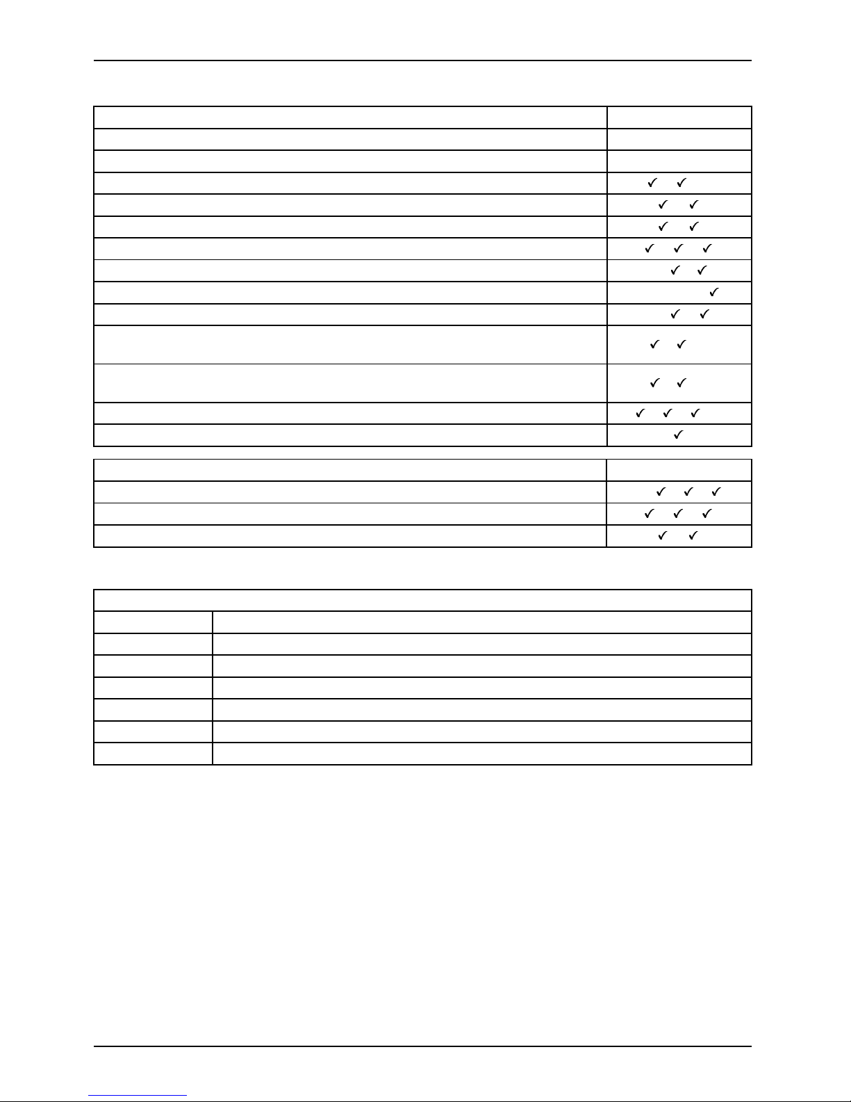
Internal connectors and slots
List of onboard Features D3171
Chipset Intel®B75
Board size µATX
DVI-D / VGA / DisplayPort / /Stereo Audio / 5.1 Multichannel Audio /
Buzzer / int. Speaker Suppo
rt
/
LAN 1 Gbit / 100 Mbit/ 10 Mbit / /
LAN ASF /Aol / WoL / Remote Boot /iAMT - / - / / /SATA2 / SATA3 / RAID / eS
ATA-support
3/1/-/
FireWireTM / USB 2.0 / USB 3.0 - / /
FAN monitored PSU* / CPU FAN(1) / System (FAN2) / AUX2 (FAN3) /
AUX2 (FAN4)
-/
/ /-/-
FAN controlled PSU*
/ CPU FAN(1) / System (FAN2) / AUX2 (FAN3) /
AUX2 (FAN4)
-/
/ /-/-
TEMP monitored CPU / ONB1 / ONB2 / HDD / / /Fujitsu Technology Solutions Ke yboa rd Power Bu tton Support
Special on bo ard features D3171
Silent Fan / Sile
nt Fan LT / System Guard / Silent Drives
-/ / /
Recovery BIOS / Desk Update / Multi Boot / /
HDD Password / Logo Boot /
* not support
ed by standard Power Supplies
Special Features
System Guard View and adjust Silent Fan (only OEM version)
Silent Dri
ves
Noise redu
ction for o ptical and hard disk drives
Recovery BIOS Restores a c orrupted BIOS
Desk Upd
ate
Simple driver u pdate with DU CD or Internet
Multi Boot
Comfort
able boot from any boot device
HDD Passwort
Access protection for disk drives
Silent Fan LT Independent temperature related processor fan and system fan control
Fujitsu Technology Solutions
Page 7

Mainboard D3171
First-time setup
Deutsch 5
English 13
Page 8

Page 9

Inhalt Deutsch - 1
DeutschInhalt
Kurzbeschreibungdes Mainboards .................................................... 3
Anschlüsse und Steckverbinder ........................................................ 4
Prozessorein-/ausbauen ............................................................... 5
TechnischeDaten ....................................................................... 5
Vorgehensweise . . ...................................................................... 6
Hauptspeicherein-/ausbauen .......................................................... 7
BIOSUpdate ........................................................................... 8
BIOS-Update unter Windows mit dem Programm DeskFlash . . ............................. 8
BIOS-Update mit einem USB-Stick ....................................................... 8
Fujitsu Technology Solutions 5
Page 10

Intel, Pentium und Celeron sind eingetrag ene Warenzeichen der Intel Corporation, USA.
Windows 7, Windows Vista und Windows X P sind eingetragene Warenzeichen der Microsoft
Corporation.
PS/2 und OS/2 Warp sind eingetragene Warenzeichen von International Business Machines, Inc.
Alle weiteren genannten Warenzeichen sind Warenzeiche n oder eingetragene Warenzeichen
der jeweiligen Inhaber und werden als geschützt anerkannt.
Copyright © Fujitsu Technology Solutions GmbH 2012
Alle Rechte vorbehalten, insbesondere (auch auszugsweise) die der Übersetzung, des
Nachdrucks, der Wiedergabe durch Kopieren oder ähnliche Verfahren.
Zuwiderhandlungen verpflichten zu Schadenersatz.
Alle Rechte vorbehalten, insbesondere für den Fall der Patenterteilung oder GM-Eintragung.
Liefermöglichkeiten und technische Änderungen vorbehalten.
Page 11

Kurzbeschreibung des Mainboards De
utsch - 3
Kurzbeschreibung des Mainboa
rds
Hinweise zu den Baugruppen
Beachten Sie bei Baugruppen mit EGB unbedingt Folgendes:
• Sie müssen sich statisch entladen (z. B. durch Berühren eines geerdeten
Gegenstands), bevor Sie mit Baugruppen arbeiten.
• Verwendete Geräte und Werkzeuge müssen frei von statischer Aufladung sein.
• Ziehen Sie den Netzstecker, b evor Sie Baugruppen stecken oder ziehen.
• Fassen Sie die Baugruppen nur am Rand an.
• Berühren Sie keine Anschluss-Stifte oder Leiterbahnen auf der Baugruppe.
Eine Übersicht der Leistungsmerkmale finden Sie im Datenblatt.
Besondere Merkmale
Ihr Mainboard ist in verschiedenen Ausbaustufen erhältlich. Abhängig von der Konfiguration
Ihres Mainboards besitzt oder unterstützt das Mainboard bestimmte Merkmale.
In diesem Handbuch finden Sie die wichtigsten Eigenschaften dieses Mainboards beschrieben.
Weitere Informationen zu Mainboards finden Sie im Handbuch "Basisinformationen Mainboard"
auf der CD "User Documentation" oder "OEM Mainboard" bzw. im Internet.
Fujitsu Technology Solutions 7
Page 12
4 - Deutsch Anschlüsse und Steckverb
inder
Anschlüsse und Steckverbinde
r
Die Position der Anschlüsse und Steckverbinder Ihres M ainboards finden
Sie am Anfang des Handbuches.
Die markierten Komponenten und Steckverbinder müssen nicht auf
dem Mainboard vorhanden sein.
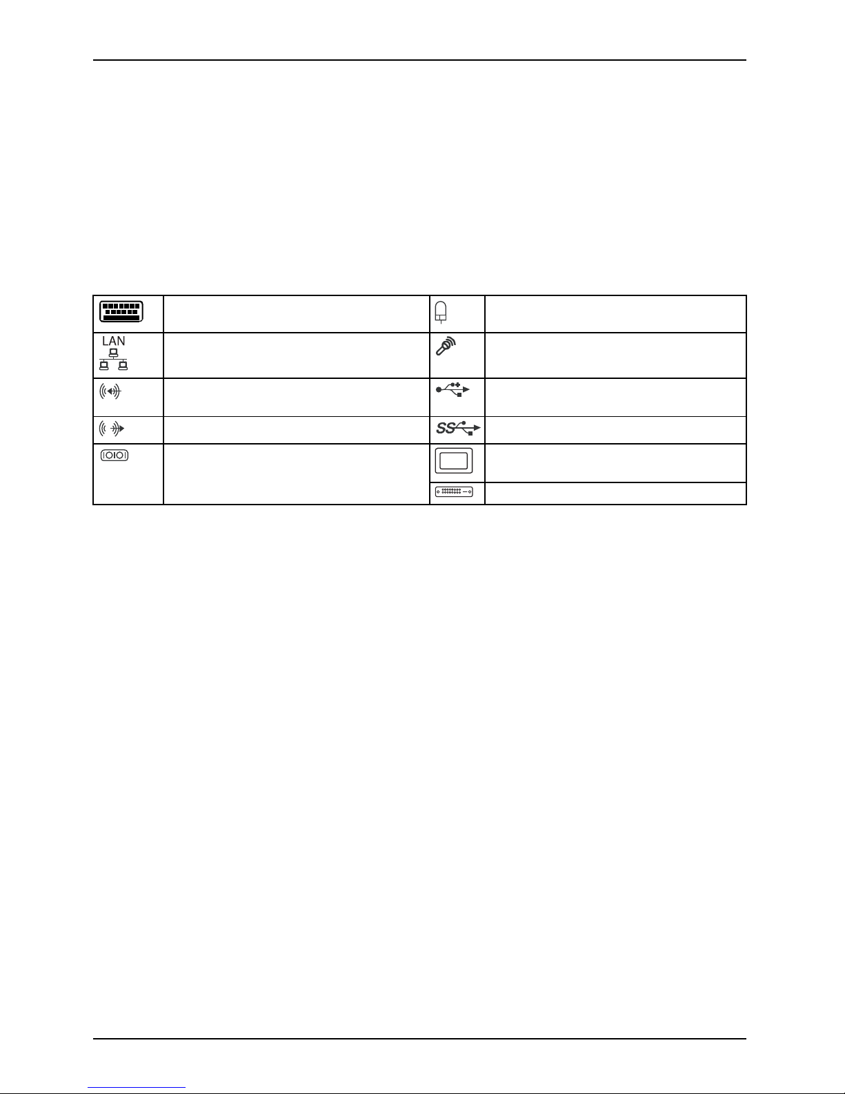
Externe Anschlüsse
Die Position der externen Anschlüsse Ihres Mainboards finden S ie am Anfang des Handbuches.
PS/2-Tastaturanschluss, violett PS/2-Mausanschluss, grün
LAN-Anschluss (RJ-45) Mikrofonanschluss, rosa
Audioeingang (Line in), hellblau USB 2.0 – Universal Serial Bus,
schwarz
Audioausgang (Line out), hellgrün USB 3.0 – Universal Serial Bus, blau
VGA, blauSerielle Schnittstelle, türkis
DVI – D
8 Fujitsu Technology Solutions
Page 13
Prozessor ein-/ausbauen Deutsch - 5
Prozessor ein-/ausbauen
Für alle hier beschriebenen Arbeiten muss Ihr System vollständig von der Netzspannung
getrennt sein! Nähere Angaben dazu finden Sie in der Betriebsanleitung Ihres Systems.
Technische Daten
• Sockel LGA 1155, max. 95W
• Eine aktuelle Liste der von diesem Mainboard unterstützten Prozessoren finden
Sie im Internet unter: "
http://ts.fujitsu.com/mainboards".
Fassen Sie auf keinen Fall die Unterseite des Prozessors an. Schon leichte
Verunreinigungen wie Fett von der Haut können die Funktion des Prozessors
beeinträchtigen oder den Prozessor zerstören. Setzen Sie den Prozessor mit
großer Sorgfalt in den Steckplatz, da die Federkontakte des Steckplatzes sehr
empfindlich sind und nicht verbogen werden dürfen.
Sind ein oder mehrere Federkontakte verbogen, setzen Sie auf keinen Fall
den Prozessor ein, da dieser dadurch beschädigt werden könnte. Wenden
Sie sich bitte direkt an Ihren zuständigen Händler
Fujitsu Technology Solutions 9
Page 14
6 - Deutsch Prozessor ein-/ausb auen
Vorgehensweise
Der Steckplatz für Prozessor ist zum Schutz der Federkontakte mit einer Schutzkappe
abgedeckt. Im Gara ntiefall kann das Mainboard nur mit befestigter Schutzkappe
von Fujitsu Technology Solutions zurück genommen werden!
a
b
b
► Entfernen Sie den Kühlkörpe
r.
► Drücken Sie auf den Hebel und
haken Sie ihn aus.
► Klappen Sie die Halterun
g nach oben.
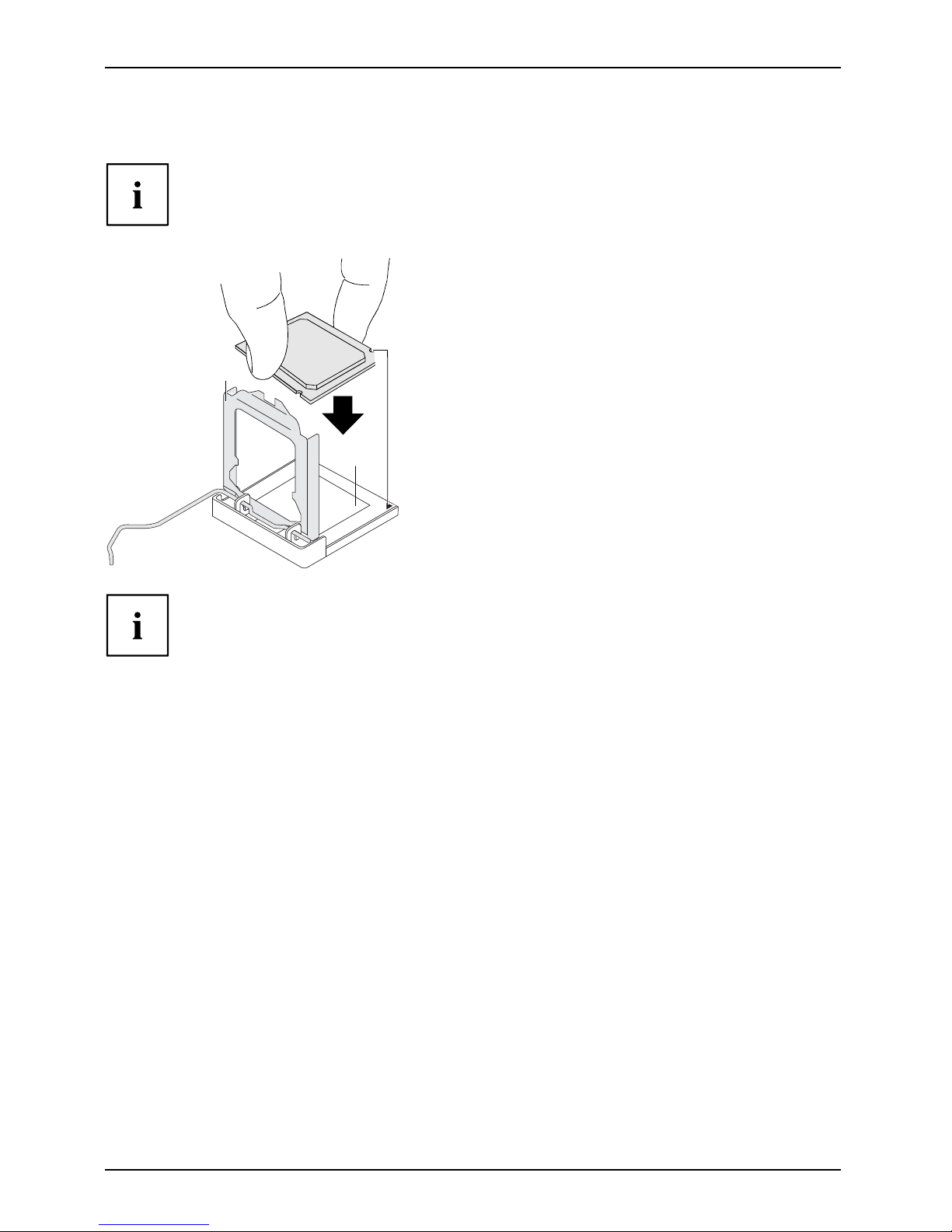
► Halten Sie den Prozessor mit Daumen
und Zeigefinger und stecken Sie ihn
so in den Steckplatz (b), dass die
Markierung des Prozessors mit der
Markierung am Steckplatz von der Lage
her übereinstimmt (a).
► Drücken Sie den Hebe
l nach unten,
bis er wieder einhak
t.
► Entfernen Sie die Schutzklappe und
verwahren Sie diese.
Bitte beachten Sie, dass je nach verwendetem Kühlkörper unterschiedliche
Kühlkörperhalterungen auf dem Mainboard benötigt werden.
► Je nach Ausbau
-Variante müssen Sie eine Schutzfolie vom Kühlkörper abziehen oder den
Kühlkörper mi
t Wärmeleitpaste bestreichen, bevor Sie ihn aufsetzen.
► Befestigen Sie den Kühlkörper - je nach Ausführung - mit vier Schrauben
oder stecken Sie ihn in die Befestigungen.
10 Fujitsu Technology Solutions
Page 15
Hauptspeicher ein-/ausbauen Deuts
ch - 7
Hauptspeicher ein-/ausbauen
Technische Daten
Technologie
DDR3 1333 / 1600 MHz ungepufferte DIMM Module 240-Pin; 1,5 V;
64 Bit, ohne ECC
Gesamtgröße 1 bis 32 GByte DDR3
Modulgröße 1, 2, 4 oder 8 GByte pro Modul
Eine aktuelle Liste der für dieses Mainboard empfohlenen Speichermodule finden
Sie im Internet unter: "
http://ts.fujitsu.com/mainboard s".
Es muss mindestens ein Speichermodul eingebaut sein. Speichermodule mit
unterschiedlicher Speicherkapazität können kombiniert werden.
Es dürfen nur unge pufferte D DR3-Speichermodule ohne EC C verwendet werden.
DDR3-Speichermodule müssen der PC3-10600- oder PC3-12800-Spezifikation
entsprechen.
Wenn Sie mehr als ein Speichermodul verwenden, dann achten Sie darauf,
die Speichermodule auf beide Speicherkanäle aufzuteilen. Dadurch nutzen
Sie die Performancevorteile des Dual-Channel-Mode.
Die maximale Systemperformance ist gegeben, wenn in Channel A und
Channel B identische Speichermodule verwendet werden.
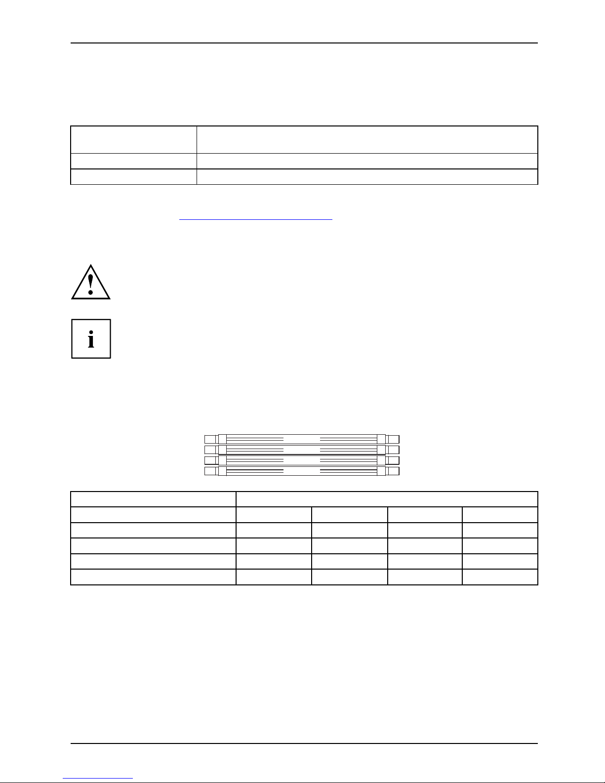
Um die Bestückung zu erleichtern, sind die Steckplätze (Slots) farbig gekennzeichnet.
Abhängig von der Systemkonfiguration kann sich der sichtbare Hauptspeicher reduzieren.
Channel B
Channel B
Channel A
Channel A
2
4
1
3
Anzahl der gesteckten Speichermodule
Zu verwendender Steckplatz 1 2 3 4
Channel A, Slot 1
xxxx
Channel B, Slot 2
xxx
Channel A, Slot 3
xx
Channel B, Slot 4
x
Der Ein-/Ausbau ist im Handbuch "Basisinformationen Mainboard" beschrieben.
Fujitsu Technology Solutions 11
Page 16

8 - Deutsch BIOS Update
BIOS Update
Wann sollte ein BIOS-Update durchgeführt werden?
Fujitsu Technology Solutions stellt neue BIOS-Versionen zur Verfügung, um die Kompatibilität
zu neuen Betriebssystemen, zu neuer Software oder zu neuer Hardware zu gewährleisten .
Außerdem können neue BIOS-Funktionen integriert werden.
Ein BIO S-Upd a te sollte auch immer dann durchgeführt werden , wenn ein Problem besteht,
das sich durch neue Treiber oder neue Software nicht beheben lässt.
Wo gibt es BIOS- U pdates?
Im Internet unter "
http://ts.fujitsu.com/mainboard s" finden Sie die BIOS-Updates.
BIOS-Update unter
Windows mit dem
Programm DeskFlash
Ein BIOS-Update
kann unter Windows auch mit dem Programm DeskFlash durchgeführt werden.
Das Programm Des
kFlash finden Sie auf dem Datenträger "Drivers & Utilities" (unter Flash BIOS).
oder
► Laden Sie die Up
date-Datei für " Flash BIOS Update – Desk Flash Instant"
von unserer In
ternet-Seite a u f Ihren PC .
► Führen Sie die Update-Datei aus.
► Folgen Sie de
n B ildschirmanweisungen.
BIOS-Update mit einem USB-Stick
► Halten Sie einen bootfähigen USB-Stick bereit.
► Laden Sie
die "Admin package - Compressed Flash Files" für bootfähige
USB-Stic
ks von unserer Internet-Seite auf Ihren PC.
► Entpacken Sie die ZIP -Datei und kopieren Sie die Dateien au f Ihren bootfähigen USB-Stick.
► Starten
Sie den PC neu.
► Wählen Sie den USB-Stick als Boot Device.
► Booten
Sie von dem USB-Stick und starten sie DosFlash.BAT.
► Folgen Sie den Bildschirmanweisungen.
12 Fujitsu Technology Solutions
Page 17

Contents English - 1
EnglishContents
Brief description of mainboard . . ....................................................... 3
Interfaces and connectors . . ........................................................... 4
Installing/removing the processor ...................................................... 5
Technicaldata .......................................................................... 5
Procedure . . . . .......................................................................... 6
Installing/removing main memory .. . ................................................... 7
BIOSUpdate ........................................................................... 8
BIOS update under Windows with DeskFlash program . .................................... 8
BIOSupdate using aUSBstick .......................................................... 8
Fujitsu Technology Solutions 13
Page 18

Intel, Pentium and Celeron are registered trademarks of Intel C orporation, USA.
Windows 7, Windows Vista and Windows XP are registered trademarks of Microsoft Corporation.
PS/2 and OS/2 Warp are registered trademarks of International Business Machines, Inc.
All other trademarks used in this document are trademarks or registered trad emarks of
their respective owners and are recognised as being protected.
Copyright © Fujitsu Technology Solutions GmbH 2012
All rights, including rights of translation, reproduction by printing, copying or similar
methods, of the whole document or parts thereof, are reserved.
Offenders will be liable to prosecution and payment of damages.
All rights reserved, including rights crea ted by patent grant or registration of a utility model or design.
Delivery subject to availability. We reserve the right to make technical modifications to the product.
Page 19

Brief description of mainboard Engl
ish - 3
Brief description of m ainboar
d
Information about boards
Be sure to observe the following for boards with ESD:
• You must always discharge static build up (e.g. by touching a grounded object)
before working with the board.
• The equipment and tools you use must be free of static charge.
• Remove the power plug from the mains supply before inserting or removing
boards.
• Always hold boards by their edges.
• Never touch connector pins or conductors on the board.
An overview of the features is provided in the data sheet.
Special features
Your mainboard is available in different configuration levels. Depending on the configuration,
your mainboard will be equipped with or provide support for certain features.
This manual describes the most important properties of this mainboard.
Additional information on mainboards is provided in the manual "Basic information on mainboard"
on the "User Documentation" or "OEM Mainboard" CD, or on the Internet.
Fujitsu Technology Solutions 15
Page 20
4 - English Interfaces and connector
s
Interfaces and connectors
The location of the interfaces and connectors of your mainboard is specified
at the beginning of the manual.
The components and connectors marked are not necessarily present on the mainboard.
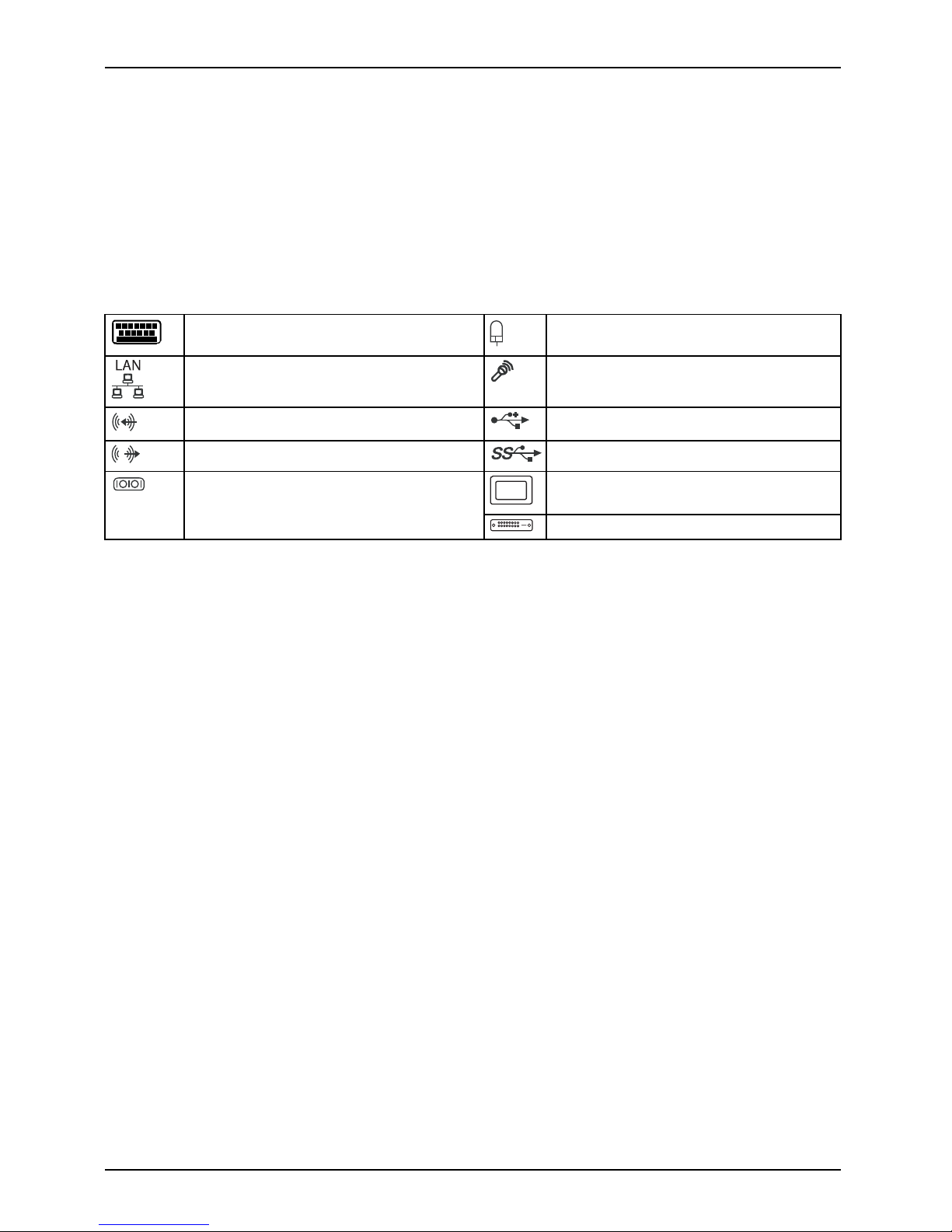
External ports
The location of the externa l connections of your mainboard is specified at the beginning of the manual.
PS/2 keyboard port, purple PS/2 mouse port, green
LAN port (RJ-45) Microphone jack (mono), pink
Audio input (Line in), light blue USB 2.0 – Universal Serial Bus, black
Audio output (Line out), light green USB 3.0 – Universal Serial Bus, blue
VGA, blueSerial interface, turquoise
DVI–D
16 Fujitsu Technology Solutions
Page 21
Installing/removing the processor
English - 5
Installing/removing the proc
essor
Disconnect the system from t he mains voltage before performing any of the tasks
described below. Details are contained in the operating manual of your system.
Technical data
• Socket LGA 1155, max. 95
W
• A current list of the processors supported by this mainboard is available on the
Internet at: "
http://ts.fujitsu.com/mainboards".
Never touch the underside of the processor. Even minor soiling such as grease
from the s kin can impair the processor’s operation or destroy the processor.
Place the processor in the socket with extreme care, as the spring contacts
of the socket are very delicate and must n ot be bent.
If one or more spring contacts are bent, on no accou nt insert the processor as it
may be damaged by doing so. Please contact the responsible vendor.
Fujitsu Technology Solutions 17
Page 22
6 - English Installing/removing the
processor
Procedure
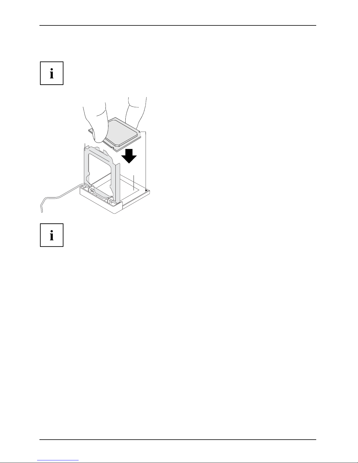
The processor socket is covered with a protective cap to protect the spring
contacts. In the event of a warranty case, the mainboard can only be taken back
by Fujitsu Te chn ology Solutions with the protective cap secu red!
a
b
b
► Remove the heat sink.
► Press down the lever and unhook it.
► Fold up the frame.
► Hold the processor between you r thumb
and index finger and insert it into the socket
(b) so that the marking of the processor is
aligned with the marking on the socket (a).
► Press the lever downward until it is
hooked in again.
► Remove the protective cap and keep it.
Please note that
, depending on the heat sink used, different heat sink
mounts a re requi
red on the mainboard.
► Depending on the configuration variant, you must pull a protective foil off the heat sink
or coat the heat sink with heat conducting paste before fitting it.
► Secure the heat sink - depending on the m od el - with four screws or push it into the mounts.
18 Fujitsu Technology Solutions
Page 23
Installing/removing main memory En
glish - 7
Installing/removing main mem
ory
Tech nical data
Technology
DDR3 13 33/1600 MHz unbuffered DIMM modules 240 pin; 1.5 V;
64 bit, no ECC
Tot al siz e
1to32GByteDDR3
Module size
1, 2, 4 or 8 GByte per module
A current list of the m emo ry modules recommended for this mainboard is available
on the Internet at: "
http://ts.fujitsu.com/mainboards".
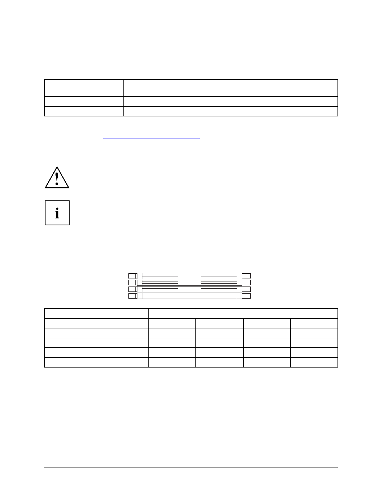
At least one memory module must be installed. Memory modules with differen t
memory capacities can be combined.
Only unbuffered DDR3 memory modules without ECC may be used.
DDR3 memory modules must comply with the PC3-10600 or PC3-12800 specification.
If you use more than one memory module, then make sure to distribute the
memory modules over both memory channels. By doing this you use the
performance advantages of the dual-channel mode.
Maximum system pe rformance is achieved when identical memory modules
are used in Channel A and Channel B.
To simplify equipping, the slots are colour coded.
Depending on how the system is configured, the visible main memory can be reduced.
Channel B
Channel B
Channel A
Channel A
2
4
1
3
Number of memory modules inserted
Slot to be
used
1234
Channel A, slot 1
xxxx
Channel B, slot 2
xxx
Channe
lA,slot3
xx
Channel B, Slot 4
x
The installation/removal is described in the "Basic information on mainboard" manual.
Fujitsu Technology Solutions 19
Page 24

8 - English BIOS Update
BIOS Update
When should a BIOS update be performed?
Fujitsu Technology Solutions makes new BIOS versions a vailable to ensure compatibility with new
operating systems, new software or new hardware. In addition, new BIOS functions can be integrated.
A BIOS update should also always be performed if there is a pro blem that cannot
be solved using new drivers or new software.
Where can I obtain BIOS updates?
Go to "
http://ts.fujitsu.com/mainboards" to find the BIOS updates.
BIOS update under Wi
ndows with DeskFlash program
A BIOS update can also be carried out under Windows with the D eskFlash program. The DeskFlash
program is located on the "Drivers & Utilities" data carrier (under Flash BIOS).
or
► Download the "Flash BIOS Update – Desk Flash Instant" update file from our website to your PC.
► Run the update file.
► Follow the on-scre en instructions.
BIOS update using a USB stick
► Make sure you have a bootable USB stick available.
► Download the "Admin package – Compressed Flash Files" for bootable USB
sticks from our website to your PC.
► Unzip the ZIP file and copy the files onto your bootable USB stick.
► Reboot the PC.
► Select the USB stick as the boot device.
► Boot from the USB stick and start DosFlash.BAT.
► Follow the on-scre en instructions.
20 Fujitsu Technology Solutions
 Loading...