

Page 1
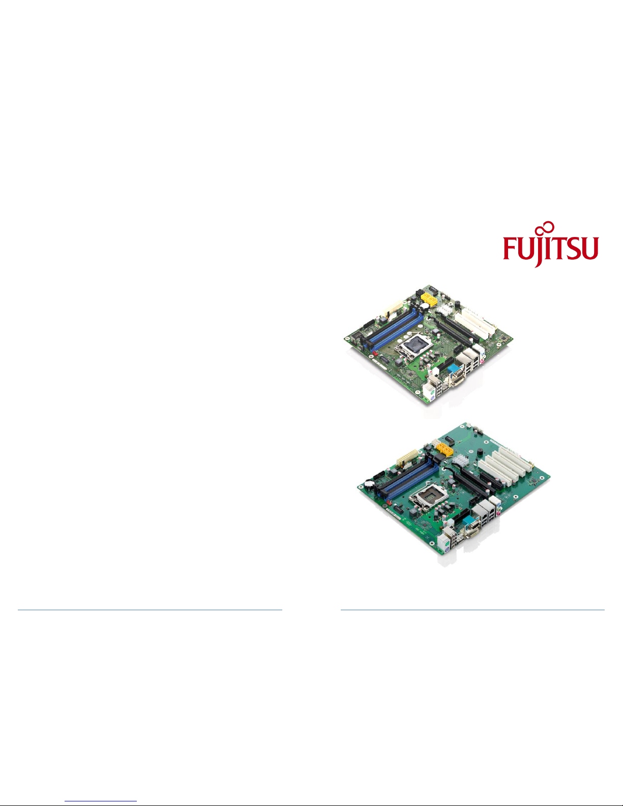
TechNotes V2.0
Industrial Mainboards
D3071-S / D3076-S
Page 2

a
Content
1 Safety Instructions 4
2 Feature Overview D307x-S 5
2.1 Basic Layout 9
2.2 Block Diagram 10
2.3 External Connectors D3071-S 11
2.4 External Connectors D3076-S 12
2.5 Onboard components D3076-S 13
2.6 Onboard components D3071-S 14
2.7 I/O-Shield 15
3 Interfaces & Connectors 17
3.1 Frontpanel Connector 17
3.2 Internal Parallel Port Connector 18
3.3 Internal COM2 Connector 18
3.4 Internal USB Connector (2 x 2 Ports) 19
3.5 Internal USB Flash Drive Connector (1 port) 19
3.6 Internal USB Stick Connector (1 port) 19
3.7 Fan Connector 20
3.8 Power Supply Fan Connector 20
3.9 High Definition Frontpanel Audio Connector (HD Audio) 21
3.10 AC97 Frontpanel Audio Connector (Legacy Audio) 21
3.11 Power Supply Connector 22
3.12 Additional Power Supply Connector 22
3.13 GPIO Connector 23
3.14 Chassis Intrusion 24
4 System Monitoring 25
4.1 D307x-S: Temperature Sensors and Fan Connectors 26
4.2 D307x-S: SystemGuard 27
4.3 D307x-S: SystemGuard - Details 28
Page 3

a
4.4 SilentFanConfigManager – Customize System Monitoring Settings 29
4.5 Components for continous operation @ 60°C 32
4.6 Capacitor Endurance Time Comparison 33
4.7 Thermography D307x-S 34
4.8 Temperature Reference Points D307x-S 35
5 Power Supply 36
5.1 ATX Power Supply 36
6 Display Options 37
6.1 VGA Output 37
6.2 DVI Output 38
6.3 HDMI Output 39
6.4 DisplayPort Output 40
6.5 Dual DVI Output 41
6.6 Multi Monitor Output 42
7 Operating System Support 43
7.1 Support for Windows XP / Windows 7 44
7.2 Linux Status 45
8 Mainboard Tools 46
Common Mainboard Tools 46
8.1 BIOS Boot Logo Tool 46
8.2 EditCMOS 46
8.3 OEMIDENT 46
8.4 SystemGuard 47
Industrial Tools 48
8.5 SilentFanConfig-Manager 48
8.6 Windows System-Monitoring API (BMCAPI) 48
8.7 Linux System-Monitoring Driver (“LM-Sensors”) 48
9 Known Issues & Important Notes 49
9.1 Windows XP Installation in AHCI mode – necessary adjustments 49
9.2 RAID / AHCI driver disk installation (Windows XP) from floppy disk 50
10 Miscellaneous 51
10.1 System Watchdog (WD) 51
10.2 BIOS Update / BIOS Recovery 54
Page 4

a
1 Safety Instructions
Safety Instructions
Do not connect or disconnect any cables or modules to or from any onboard connectors (except
for the rear I/O connectors) until the mainboard is completely powered down.
Any damage caused t o the mainboard b y misuse of the onboard connectors is excluded from t he
standard warranty. Fujitsu Technology Solutions cannot be held liable for any damage that results
from incorrect use of any onboard connectors.
The system integrator is fully responsible for the usage of appropriate connectors and cables in
order to fulfill the technical requirements (electrical contact, durability, power/current levels,
signal integrity etc.)
Page 5

a
2 Feature Overview D307x-S
• Based on latest Intel
Cougarpoint
single-chip technology (iQ67)
• Support for full range of latest LGA1155 processors (up to 95W)
• Intel® Core™ i7 – 2xxx processor series
• Intel® Core™ i5 – 2xxx processor series
• Intel® Core™ i3 – 2xxx processor series
• Intel® Pentium® G8xx/G6xx processor series
• Intel® Celeron® Gxxx processor series
Note: Intel
IvyBridge
processors (22nm) are not supported!
• iAMT 7 / VPro 2011 Manageabilty Support
Note: Available feature set depends on installed processor
• Four memory sockets DDR3/1333 supporting up to 32GB
• 15µ gold plating for improved durability and reliability
• Dual Intel Gbit LAN onboard
• Link Aggregation support (Teaming, Bonding)
• iAMT support
Page 6

a
Feature Overview D307x-S
• Trusted Platform Module TPM V1.2 (Infineon) onboard
• Latest Intel® HD Graphics (integrated in processor)
• Simultaneous use of integrated graphics and PCIe graphics possible
• PCI Express Gen2
• State-of-the-art performance provided by all PCIe extension slots
• 5.1 multichannel audio onboard
• 8-Bit GPIO onboard
• 6-Layer PCB (Tin Plating)
• Improved electrical signal quality
• Improved durability
Page 7
a
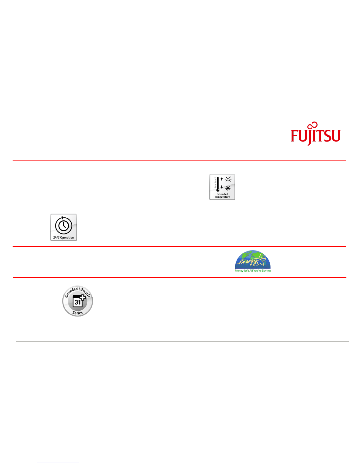
Feature Overview D307x-S
Designed & approved for enhanced operating temperature
range from 0°C to 60°C
Designed & approved for 24/7 continuous operation
High Efficient core voltage regulator design (89% @ 65W, 86% @ 95W)
Extended lifecycle up to 5 years
Page 8
a
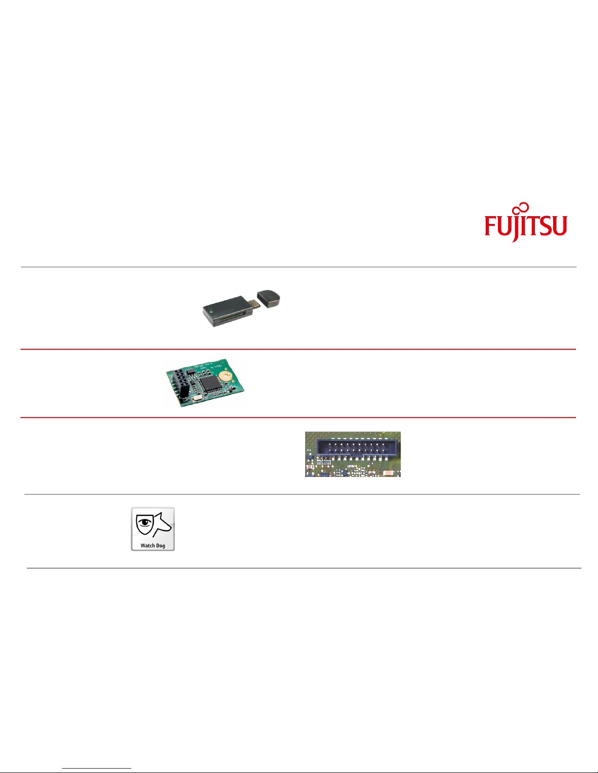
Feature Overview D307x-S
Internal socket for USB stick
Install your USB dongle inside
the chassis w/o danger of theft
Avoids possible EMI issue with
external USB stick
Internal socket for USB flashdrive
Easy integration of flashdrives for Embedded OS or memory
extension. Mainboard prepared for mechanical fastener
8 Bit GPIO Port
Easy extension e.g. for status LEDs
Easy SW integration via Windows API
Pin layout compatible with D2703-S, D2963-S, D3003-S
Hardware Watchdog
Incl. BIOS/Boot and OS supervision
Easy SW integration via Windows API & Linux Driver
Page 9
a
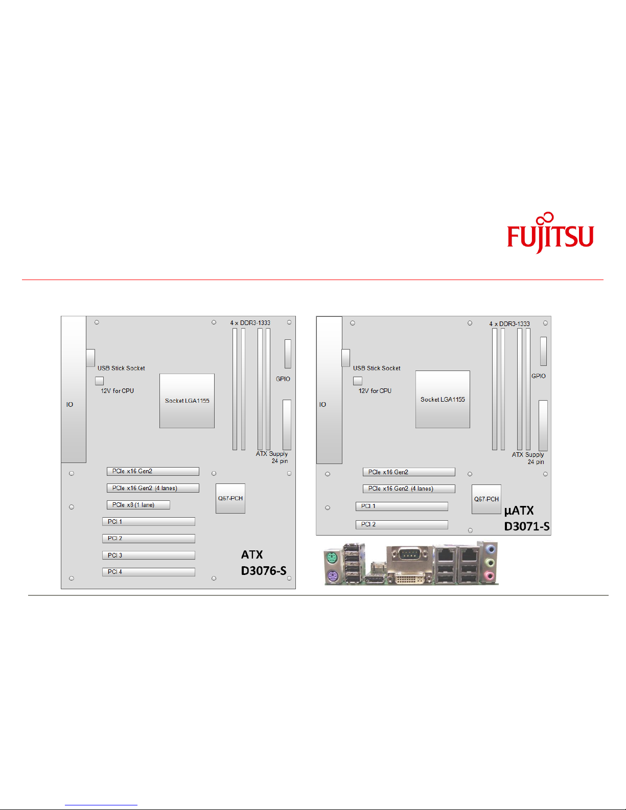
Feature Overview D307x-S
2.1 Basic Layout
Page 10

Feature Overview D307x-S
2.2 Block Diagram
SM Bus
SPI Bus
PCIe x16
PCIe Link
FDI-Link
PCIe x16
Slot
Memory Bus Channel B
DMI Link
2 DIMM Sockets
DDR 3 with 1066/1333
PCI-Bus
LGA1155 CPU
Intel PCH
Clock
Synthesizer
HD Audio Link
LPC-Bus
2 DIMM Sockets
DDR 3 with 1066/1333
Audio
Conexant
20642
PCI Slots
32Bit / 33MHz
Super I/O
SMSC
SCH5636
2x Serial Port
Serial Ports
PS2 Ports
Intrusion
Serial ATA
6 Channels
14 USB Ports
PCIe x1 or
PCIe x8
(1 lane)
Slots
I/O Rear: Micro In
PCIe Link
I/O Rear: Line out
I/O Rear: Line in
I/O Front: Head out
I/O Front: Micro in
Internal: Speaker
TPM 1.2
Infineon
Ethernet1
Intel
82579DM
LAN RJ45
SPI Flash
BMC
Parallel Port
Memory Bus Channel A
Video
VGA,DVI,
DisplayPort-
Support
Ethernet2
Intel
82574L
LAN RJ45
Page 11

Feature Overview D307x-S
2.3 External Connectors D3071-S
PS/2 Kbd-Mouse
4 x USB 2.0
DisplayPort
COM1; DVI-I
LAN2; 2 x USB 2.0
LAN1; 2 x USB 2.0
Audio
Page 12

a
Feature Overview D307x-S
2.4 External Connectors D3076-S
PS/2 Kbd-Mouse
4 x USB 2.0
DisplayPort
COM1; DVI-I
LAN2; 2 x USB 2.0
LAN1; 2 x USB 2.0
Audio
Page 13

a
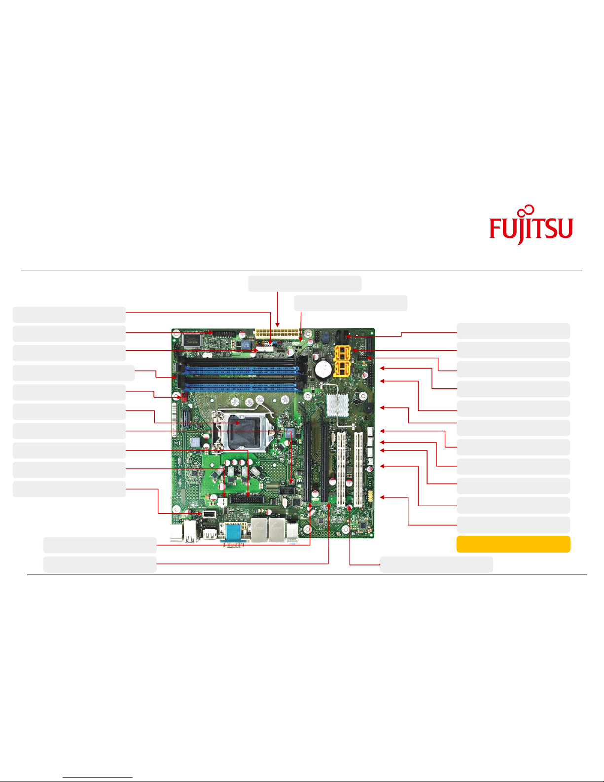
Feature Overview D307x-S
2.5 Onboard components D3076-S
Intrusion
Frontpanel Audio
Fan 2 (PWM)
Fan 3 (PWM or 3-pin)
Buzzer
2 x USB
2 x USB
6 Layer PCB
4 x PCI
PCIe x8 (1 Lane, Gen2)
PCIe x16 (16 Lanes, Gen2)
PCIe x16 (4 Lanes, Gen2)
Fan 4 (PWM)
1 x USB (Flashdrive)
4 x SATA II
Socket for USB Stick
12V Supply (Processor)
Parallel Port
COM2 Port
Processor LGA1155
Processor Fan (PWM)
4 x DDR3 (15µ gold plating)
PS Fan Control
8 Bit GPIO
Frontpanel
2 x SATA III
SCSI LED
24 pin ATX PS
Page 14
a
Feature Overview D307x-S
2.6 Onboard components D3071-S
Frontpanel
8 Bit GPIO
PS Fan Control
4 x DDR3 (15µ gold plating)
Processor Fan (4 pin)
Processor LGA1155
COM2 Port
Parallel Port
12V Supply (Processor)
Socket for USB Stick
PCIe x16 (16 Lanes, Gen2
PCIe x16 (4 Lanes, Gen2)
24 pin ATX PS
SCSI LED
2 x SATA III
4 x SATA II
1 x USB (Flashdrive)
2 x USB
2 x USB
Buzzer
Fan 4 (supports 3 & 4 pin)
Fan 3 (4 pin)
Fan 2 (4 pin)
Intrusion
Frontpanel Audio
6 Layer PCB
2 x PCI
Page 15

a
Feature Overview
2.7 I/O-Shield
Spring Steel Sheet
Enforcement Sheet
Spring Steel Sheet
Gasket = Foam with
Aluminium
(front view)
(rear view)
Page 16

a
Feature Overview
I/O-Shield
Apparatus to evaluate and specify
insertion force of FTS IO shield.
Nominal force: ~ 150 – 200 N
for specified ATX IO “letterbox”
Note: ATX Chassis “letterbox” for I/O shield:
Nom. size = 158.75 x 44.45mm
Tolerance = +/- 0.2mm
Page 17

a
3 Interfaces & Connectors
3.1 Frontpanel Connector
Power LED:
Anode: Pin 2 – 80R Pullup to 5V_AUX
Cathode: Pin 4 – output (12mA)
Alert LED:
Anode: Pin 13 - 220R Pullup to 3,3V
Cathode: Pin14 – output (4mA)
HDD LED:
Anode: Pin 1 – 365R Pullup to 5V
Cathode: Pin 3 – output (6mA ; ~ 0.7V low level)
Speaker Output:
Differential audio signal; max. 0.5W / 8Ohm
Page 18
a
Interfaces & Connectors
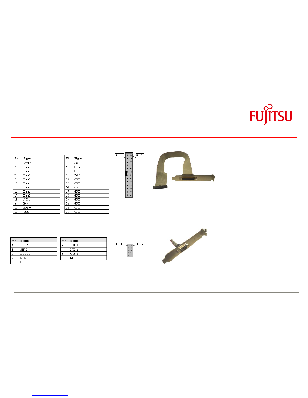
3.2 Internal Parallel Port Connector
3.3 Internal COM2 Connector
optional Parallelport cable
with ATX bracket
optional COM2-cable
with ATX bracket
Page 19

a
Interfaces & Connectors
3.4 Internal USB Connector (2 x 2 Ports)
3.5 Internal USB Flash Drive Connector (1 port)
3.6 Internal USB Stick Connector (1 port)
Page 20

a
Interfaces & Connectors
3.7 Fan Connector
Note:
3pin mode (voltage controlled): Supported by Fan3 only (3pin/4pin mode selectable in BIOS Setup)!
If a 3-wire fan is connected, but BIOS Setup is set to “4-Pin” (= Default) the fan will operate at full speed (=12V).
In 3-wire mode, the default minimum operating voltage is set to ~ 6V.
3.8 Power Supply Fan Connector
Note: This feature is not supported by standard ATX power supplies!
Fan4 and PS Fan connector must not be used simultaneously!
Note:
Fans must never be attached or
removed while the system is
powered. Mainboard may be
damaged!
Page 21

a
Interfaces & Connectors
3.9 High Definition Frontpanel Audio Connector (HD Audio)
3.10 AC97 Frontpanel Audio Connector (Legacy Audio)
Note: In case of using this connector in AC97 = Legacy mode (BIOS Setting) take care for pin 7.
This pin is tied to GND. HP_ON# signaling on this pin is not supported.
Page 22

a
Interfaces & Connectors
3.11 Power Supply Connector
3.12 Additional Power Supply Connector
Page 23

a
Interfaces & Connectors
3.13 GPIO Connector
1
GPI/O_0
GPI/O_1
2 3 GPI/O_2
GPI/O_3
4 5 GPI/O_4
GPI/O_5
6 7 GPI/O_6
GPI/O_7
8 9 VCC_3.3V
GND
10
11
VCC_3.3V
VCC_5Vaux
12
13
reserved
GND
14
15
reserved
GND
16
17
GND
VCC_5V
18
19
VCC_12V
VCC_12V
20
Parameter
Range
GPI/O Input Low Voltage
-0.5V … 0.8V
GPI/O Input High Voltage
2V … 3.3V
GPI/O Output Low Voltage
max. 0.7V
GPI/O Output High Voltage
min. 2.5V
Note: max. load per GPI/O pin: 10mA
(overall current for all GPI/O pins must be < 85mA)
Each GPI/O pin has an integrated serial resistor of 150
Ohm
GPIO access is provided via the SM-Bus controller PCA9554A
ftp://ftp.ts.fujitsu.com/pub/Mainboard-OEM-Sales/Products/Mainboards/Indu
strial&ExtendedLifetime/D3071-S_D3076-S/Documentation/Specifications/GP
IO_Chip_PCA9554a.pdf
Note: SM-Bus address: 0x78h (8-bit)
For Windows OS, the FTS BMC API provides easy access to the GPIO:
ftp://ftp.ts.fujitsu.com/pub/Mainboard-OEM-Sales/Products/Mainboards/Indu
strial&ExtendedLifetime/D3071-S_D3076-S/IndustrialTools_D307x-S/BMC_Ma
nagement-Controller-API/
GPIO Connector: CompuPack R-DRK2-20-S3-SMT
Page 24

a
Interfaces & Connectors
3.14 Chassis Intrusion
Note:
The intrusion supervision feature needs to be enabled in BIOS Setup first (Menu „Security“ „Cabinet
Monitoring“).
This BIOS option is only available if pin 3 („Intrusion Switch Present“) is connected to GND!
Note:
Chassis intrusion is active even if the system is switched off (S5 state) or
disconnected from mains power.
The intrusion event is monitored by the chipset (PCH) and stored in the BIOS
Eventlog during the next Boot.
A timestamp (Boot date/time) will be added then.
Note: This timestamp does not represent date/time of the intrusion event!
If a Supervisor Password is enabled in BIOS Setup, the system will stop
during BIOS POST if an intrusion event has been detected. In order to
continue, the Supervisor Password must be entered to confirm the intrusion
event.
The intrusion status can be easily monitored by using the BMCAPI (Windows):
ftp://ftp.ts.fujitsu.com/pub/Mainboard-OEM-Sales/Products/Mainboards/Industrial&ExtendedLifetime/D3071-S_D3076-S/IndustrialTool
s_D307x-S/BMC_Management-Controller-API/
Page 25

a
4 System Monitoring
- Temperature Sensors and Fans
- SystemGuard: Fan / Temperature Monitor
- SilentFanConfig-Manager
- Thermography D307x-S
- Temperature Reference Points
Page 26
a
System Monitoring
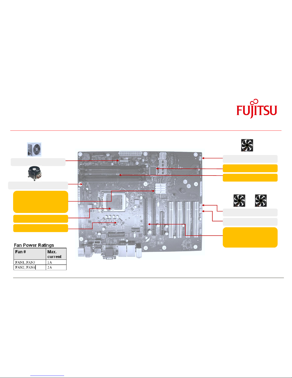
4.1 D307x-S: Temperature Sensors and Fan Connectors
PowerSupply Fan 2)
Processor Fan (Fan1,PWM)
Sensor “PCH”
(not yet available in
SystemGuard)
Sensor “Processor”
Sensor “CoreRegulator”
Fan 4 (PWM) 2)
Sensor “Super I/O”
Sensor “Memory”
Fan 3 (PWM or 3-pin) 1)
Fan 2 (PWM)
Sensor “PCIe Graphics”
(not yet available in
SystemGuard)
2) FAN 4 / PowerSupply Fan:
Connectors must not be
used simultaneously!
Selectable via BIOS Setup
Note: Do not attach more than one fan per connector!
Remove or connect fans only when unit is powered off!
1) FAN 3:
PWM or 3-Wire
Selectable via BIOS Setup
(Default = PWM)
Page 27
a
System Monitoring
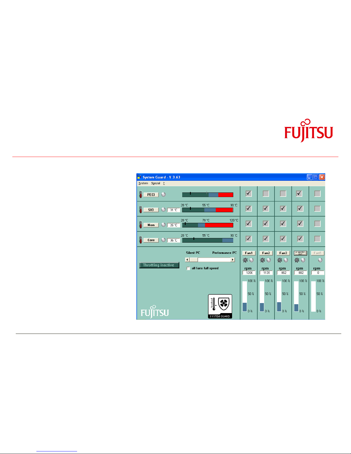
4.2 D307x-S: SystemGuard
System Monitoring Tool:
• Visualize processor and sensor
temperature data
• Display current speed for all
attached fans
• User can configure fan aging control
(menu “Special”)
• User can configure system watchdog
(menu “Special”)
User can adjust system behaviour via
“Silent PC / Performance PC” slider by
forced processor throttling
Page 28

a
System Monitoring
4.3 D307x-S: SystemGuard - Details
Temperature Sensors
Processor Sensor
1)
Super I/O Sensor
Memory Sensor
Core Voltage
Regulator Sensor
Sensor / Fan Matrix
Indicates which sensor influences the specific fan speed
Note: Characteristics for FAN1 is always dependent on the CPU
temperature – fully controlled by the system BIOS.
Due to safety reasons the influence of the CPU sensor for FAN1
cannot be disabled!
FanPS / Fan4
Displays the fan speed of Fan4 or the power supply fan
(BIOS Setup option
1) Note: As Intel has replaced the analogue processor „diode“ temperature measurement by the digital
„PECI“ measurement (Platform Environment Control Interface) which does no longer provide the absolute processor
Page 29

a
System Monitoring
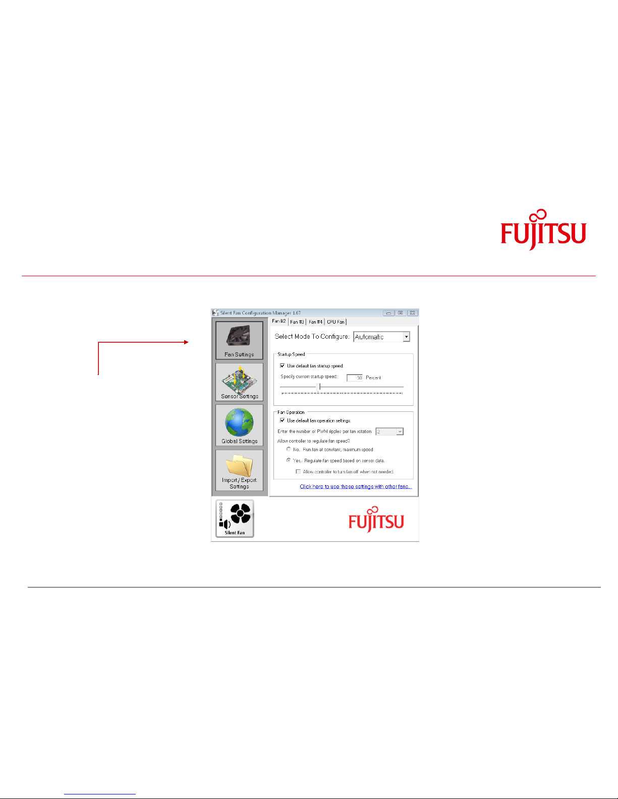
4.4 SilentFanConfigManager – Customize System Monitoring Settings
Windows-based System Management Configuration Tool
ftp://ftp.ts.fujitsu.com/pub/Mainboard-OEM-Sales/Products/Mainboards/Industrial&ExtendedLifetime/D3071-S_D3076-S/IndustrialTools_D307x-S/SilentFanConfig-Manager/
1. Windows-based configuration tool (SilentFanConfig) to create customized system monitoring settings like minimum fan speed and
temperature sensor influence. These customized settings are stored in a specific “SMCO” flash file.
2. DOS-based tool “SMCO” to flash the customized system monitoring settings (SMCO file) to the system BIOS of the target unit.
SilentFanConfig-Tool: SMCO-Tool SilentFanConfig-Tool +
Create specific system SMCO Flash File Flash SMCO file to SMCO-Tool =
monitoring settings mainboard BIOS SilentFanConfigManager
(any Windows-based PC) (each unit in production)
Note: New settings are written permanently to system BIOS.
Any BIOS update or BIOS Recovery will not reset the new settings
SilentFanConfig V1.67 or higher required for D307x-S
ftp://ftp.ts.fujitsu.com/pub/Mainboard-OEM-Sales/Products/Mainboards/Industrial&ExtendedLifetime/D3071-S_D3076-S/IndustrialTools_D307x-S/SilentFanConfig-Manager/
Page 30
a
System Monitoring
SilentFanConfigManager – Customize System Monitoring Settings
Basic fan settings:
Adjust minimum fan startup speed
(BIOS default D307x-S: 30% for all fans)
Enable/disable mainboard fan speed control
Page 31
a
System Monitoring
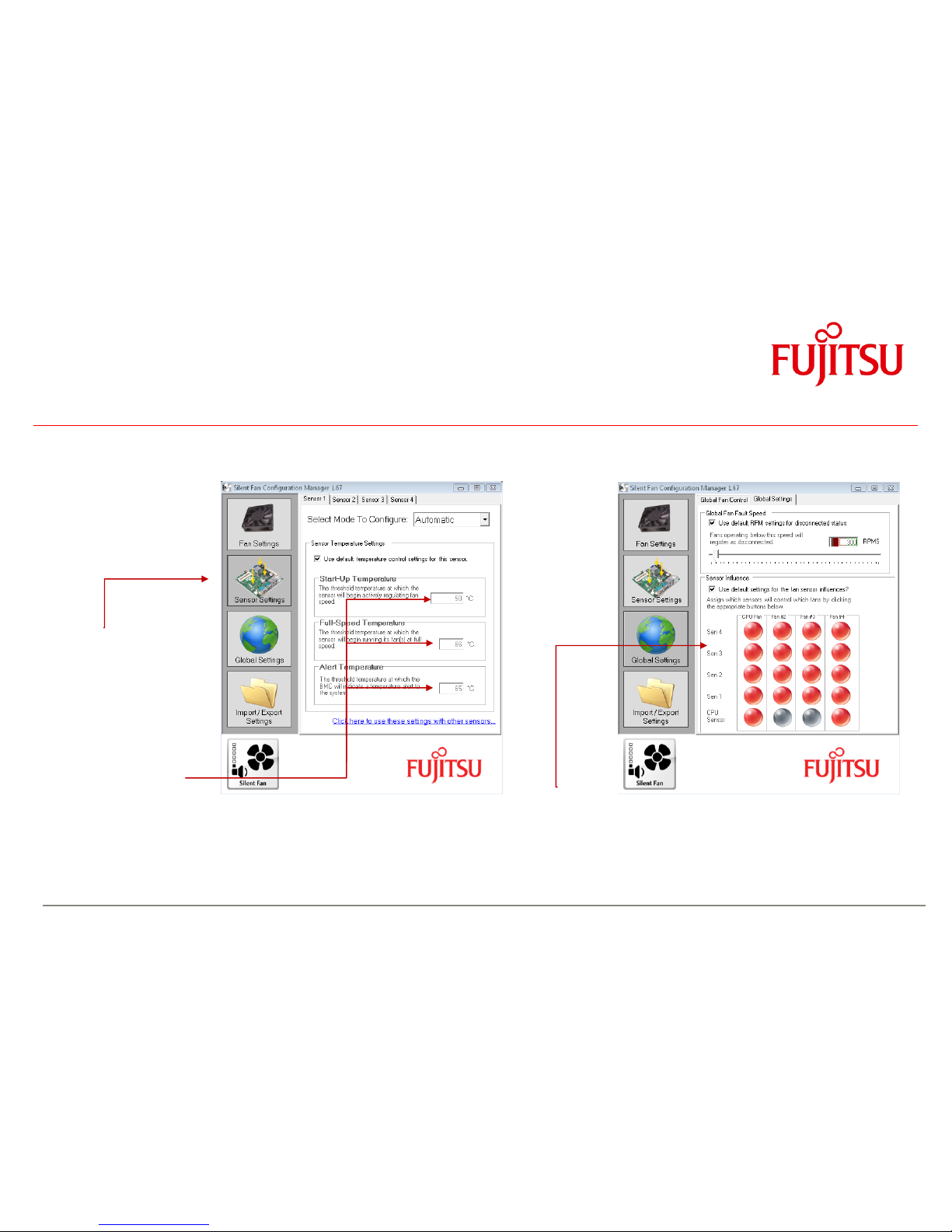
SilentFanConfigManager – Customize System Monitoring Settings
Basic sensor settings:
Sensor 1 = Super I/O
Sensor 2 = Memory
Sensor 3 = PCH
Sensor 4 = Core Voltage
Regulator
BIOS default settings D307x-S:
see data provided by
SilentFanConfig tool
Global settings:
Note: Settings for CPU sensor cannot be changed; “Red dot” indicates that sensor x controls fan y
Due to safety reasons this is fully controlled BIOS default settings D307x-S:
by the system BIOS! All sensors active, except for CPU sensor (controls CPU fan and fan4 only)
Page 32

a
Capacitor Endurance Time
Solid Electrolyte:
Fluid Electrolyte:
System Monitoring
4.5 Components for continous operation @ 60°C
Operating Conditions:
Circulating air max. 60°C
Usage 24h / 7 days
COM Driver with enhanced
operating temperature range
Quartz with enhanced
operating temperature range
Switched Voltage Regulator
instead of Linear Regulator
supporting 3-Wire FAN
(stable operation within full
temperature range)
All onboard electrolyte
capacitors: Polymer type only
(= solid electrolyte)
Sample picture: Processor Core Voltage Regulator)
Lx = effective endurance time
Lo = endurance time @ 105°C
(e.g. 2.000hrs)
to = 105°C
tx = capacitor surface temperature
(e.g. 75°C)
6-layer PCB for improved
signal quality within full
operating temperature range
High Efficiency Processor
Core Voltage Regulator
(89% @ 65W, 86% @ 95W)
for reduced thermal
dissipation loss
Extra Heatsink
on PCH (Q67)
Note: Power Consumption
PCH P max ~ 6W
P idle < 3W
Page 33

a
System Monitoring
4.6 Capacitor Endurance Time Comparison
Page 34

a
System Monitoring
4.7 Thermography D307x-S
Page 35

a
4.8 Temperature Reference Points D307x-S
Voltage Regulators max. 90°C
Quartz max. 70°C
LAN1 max. 75°C
LAN2 max. 75°C
All capacitors
max. 70°C
Audio Codec max. 70°C
Operating Conditions:
Circulating air max. 60°C
Usage 24h / 7 days
Inductor max. 90°C
Battery max. 60/70°C 1)
Inductor max. 90°C
PCH max. 75°C
(chip surface)
Voltage Regulator max. 90°C
Super I/O max. 70°C
1) Note: Battery operation is specified in
temperature range up to 60°C. Operation
between 60°C and 70°C may result in:
- Higher self discharge rate
- Decline of specified characteristics
- Danger of leakage increases
Reference Point Limit Temperatures (Component Surface) must not be exceeded!
Page 36

a
5 Power Supply
5.1 ATX Power Supply
Connectors for ATX Power Supply
(1) 24 pin connector (ATX layout)
(2) 4 pin connector (+12V, GND)
Note: The +12V supply (up to 12A) for processor and chipset is provided via the 4 pin
connector! Onboard voltage regulators convert the +12V input power to the appropriate
processor / chipset supply voltages.
(3) Processor Core Voltage Regulator: High Efficiency Design for enhanced
power saving and less thermal dissipation loss.
Requirements for ATX Power Supply
1) The ATX power supply should support the minimum load
conditions as mentioned in the chart.
Note: The max. mainboard current in the chart doesn´t include the
power for optional adapters and drives!
(3)
(2)
(1)
Page 37

a
6 Display Options
6.1 VGA Output
DVI-VGA Interface
Connector
optional: Audio
VGA
max. VGA screen resolution:
1920 x 1200
Analog (VGA) Monitor
Page 38

a
Display Options
6.2 DVI Output
max. DVI screen resolution:
1920 x 1200
Note: DVI supports Single Link only!
Digital (DVI) Monitor
DVI
optional:
Audio
Page 39

a
Display Options
6.3 HDMI Output
max. HDMI screen resolution:
1920 x 1200
HDMI transfers Video & Audio
Digital (HDMI) Monitor
Note: HDMI Audio Device needs to be
enabled via Control Panel!
HDMI
DVI-HDMI Interface
Connector
Page 40

a
Display Options
6.4 DisplayPort Output
max. DP screen resolution:
2560 x 1600
Display Port
Digital (DisplayPort) Monitor
Page 41

a
Display Options
6.5 Dual DVI Output
DisplayPort-
DVI-Converter
Cable
DVI
DVI
Dual Independent Display /
Extended Desktop
Digital (DVI) Monitor 1
Digital (DVI) Monitor 2
Page 42

a
Display Options
6.6 Multi Monitor Output
DisplayPortDVI-Converter
Cable
Digital (DVI) Monitor 1
Digital (DVI) Monitor 2
Digital (DVI) Monitor 3
Digital (DVI) Monitor 4
DVI
DVI
Simultaneous use of internal
Graphics and PCIe Graphics
DVI
DVI
Page 43

a
7 Operating System Support
- Windows® XP
- Windows® 7
- Linux
Page 44

a
Operating System Support
7.1 Support for Windows XP / Windows 7
• Mainboard D307x-S is designed according to the
Microsoft Guidelines for Windows XP and Windows 7
• MS certified drivers (32/64 Bit) are available via OEM DU-DVD
and OEM FTP Server
ftp://ftp.ts.fujitsu.com/pub/Mainboard-OEM-Sales/Products/Mainboards/Industrial&ExtendedLifetime/D3071-S_D3076-S/Drivers_D3071-S_D3076-S/
Page 45

a
Operating System Support
7.2 Linux Status
OS
Item
Debian 6
64Bit
Fedora 14
64Bit
RHEL 5.6
64Bit
RHEL 6.0
64Bit
OpenSUSE
11.3 / 64Bit
OpenSUSE
11.4 / 64Bit
SLED 11.1
/ 64Bit
Ubuntu
10.10/64Bit
Ubuntu
11.04/64Bit
PXE Install
not tested
ok
not tested
ok
ok
ok
ok
not tested
not tested
Network
ok
ok
ok
ok
ok
ok
ok
ok
ok
SATA HDD
ok
ok
ok
ok
ok
ok
ok
ok
ok
Basic X Server
ok
ok
ok
ok
ok
ok
ok
ok
ok
Shutdown/ Power off
ok
not tested
ok
ok
ok
ok
ok
not tested
ok
Save to Disk
ok
failed
ok
ok
failed
ok
ok
failed
ok
Save to RAM
ok
failed
ok
failed
ok
ok
ok
failed
ok
PS/2 Devices
not tested
not tested
not tested
ok
not tested
ok
not tested
not tested
ok
Audio Playback
ok
ok
ok
ok
ok
ok
ok
ok
ok
Audio Recording
(external source)
ok
failed
ok
failed
failed
failed
failed
not tested
failed
Page 46

a
8 Mainboard Tools
Common Mainboard Tools
8.1 BIOS Boot Logo Tool
- Tool to integrate a customized boot logo
ftp://ftp.ts.fujitsu.com/pub/Mainboard-OEM-Sales/Services/Software&Tools/Common-Mainboard-Tools/BootLogo_4_UEFI/
8.2 EditCMOS
- DOS-based production tool to change BIOS settings
and freeze customized BIOS settings (= customized default settings)
ftp://ftp.ts.fujitsu.com/pub/Mainboard-OEM-Sales/Services/Software&Tools/Common-Mainboard-Tools/EditCMOS_UEFI/
8.3 OEMIDENT
- Production tool to add MS OEM licence data (SLP1 for Windows XP and SLP2.x for
Windows Vista & Windows 7)
- Add an individual customer serial no / add a chassis asset tag
- Disable and hide TPM feature in BIOS Setup
ftp://ftp.ts.fujitsu.com/pub/Mainboard-OEM-Sales/Services/Software&Tools/Common-Mainboard-Tools/OEM-Ident/
Page 47

a
Mainboard Tools
8.4 SystemGuard
- Windows-based tool to monitor temperatures and fan speed of FTS mainboards
- Option to configure automatic fan ageing supervision
- Provides access to the System Watchdog
ftp://ftp.ts.fujitsu.com/pub/Mainboard-OEM-Sales/Services/Software&Tools/Common-Mainboard-Tools/SystemGuard/
Page 48

a
Mainboard Tools
Industrial Tools
8.5 SilentFanConfig-Manager
- Windows-based configuration tool to implement customized fan
characteristics and temperature parameters. Includes DOS-based
tool "SMCO" to flash the configuration file permanently into the system BIOS.
- Available in 03/2012
ftp://ftp.ts.fujitsu.com/pub/Mainboard-OEM-Sales/Products/Mainboards/Industrial&ExtendedLifetime/D3071-S_D3076-S/IndustrialTools_D307x-S/SilentFanConfig-Manager/
8.6 Windows System-Monitoring API (BMCAPI)
- BMC-Management-Controller to access and adjust System Monitoring parameters like
fan speed and temperatures. This API also provides access to the mainboard watchdog, the 8Bit GPIO interface and
the intrusion feature of the mainboard.
ftp://ftp.ts.fujitsu.com/pub/Mainboard-OEM-Sales/Products/Mainboards/Industrial&ExtendedLifetime/D3071-S_D3076-S/IndustrialTools_D307x-S/BMC_Management-Controller-API/
8.7 Linux System-Monitoring Driver (“LM-Sensors”)
- BMC-Management-Controller to access and adjust System Monitoring parameters like
fan speed and temperatures. This driver also provides access to the mainboard watchdog.
ftp://ftp.ts.fujitsu.com/pub/Mainboard-OEM-Sales/Products/Mainboards/Industrial&ExtendedLifetime/D3071-S_D3076-S/IndustrialTools_D307x-S/Linux_SystemMonitoring-Driver/
Note: Further details regarding mainboard tools can be found in the related “Mainboard Tools Datasheet”
ftp://ftp.ts.fujitsu.com/pub/Mainboard-OEM-Sales/Services/Software&Tools/Common-Mainboard-Tools/$$_DS_UEFI-Tools.pdf
Page 49

a
9 Known Issues & Important Notes
9.1 Windows XP Installation in AHCI mode – necessary adjustments
- Choose BIOS AHCI-mode (ADVANCED – SATA Configuration)
- Download F6 SATA Driver Disk
ftp://ftp.ts.fujitsu.com/pub/Mainboard-OEM-Sales/Products/Mainboards/Industrial&ExtendedLifetime/D3071-S_D3076-S/Drivers_D3071-S_D3076-S/
- Start the Installation of Win XP – press F6 to install SATA drivers
- Use the following Drivers for D307x-S:
- Continue the installation
Page 50

a
Known Issues & Important notes
9.2 RAID / AHCI driver disk installation (Windows XP) from floppy disk
- D307x-S doesn´t offer a legacy floppy interface
- Windows XP has some limitations regarding USB floppy support, for details see link below
http://support.microsoft.com/kb/916196
- Alternative option: Use nLite-tool to create customized XP installation CD incl. RAID/AHCI driver
www.nliteos.com/nlite.html
Page 51
a
10 Miscellaneous
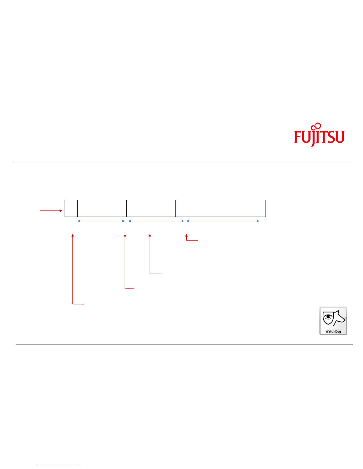
10.1 System Watchdog (WD)
D307x-S provides full BIOS POST-, Operating System Boot-, and Operating System-Runtime watchdog supervision.
Note: BIOS ≥ R1.6.0 required !
Power On Init BIOS POST OS Boot OS running
“BIOS POST Watchdog
1)
” “BIOS Boot Watchdog 1)” “OS Watchdog”
1) 2)
POST-WD-timeout = 120sec. BOOT-WD-timeout OS-WD-timeout (max. 255 minutes)
(fix defined by BMC firmware) (according to BIOS Setup) (according to specific WD software agent)
OS started. If the watchdog has been enabled by BIOS (timeout
set to xy minutes in BIOS Setup) it must be switched off or
retriggered (continuously) by a specific OS application (=WD software
agent), otherwise the system will be reset after xy minutes (= BOOT WD-timeout) respectively after nn minutes (repetitive OS-WD-timeout).
If the watchdog is enabled in BIOS Setup (timeout set to xy minutes) and the
system hangs during OS boot, the system will be reset after xy minutes.
BIOS checks at the end of POST if the watchdog must be switched off (timeout set to 0
in BIOS Setup) or retriggered according to the timeout setting in BIOS Setup (1 - 255 minutes)
BMC initializes watchdog (fixed timeout = 2 minutes; no user setting possible). If the operator runs BIOS Setup
the watchdog is set on hold. Additional PCI/PCEe extensions cards that provide an Option ROM may cause
a system reset due to BIOS POST watchdog timeout, if the user activates any menu within the Option ROM
for more than 2 minutes!
1) Note: All three watchdogs are physical identical, but they are handled from different application levels
2) As the SystemGuard tool offers access to the watchdog it can be used as “WD software agent” to retrigger the watchdog during OS runtime
Page 52

a
Miscellaneous
System Watchdog (WD)
How to handle the different watchdog levels
BIOS POST Watchdog
o No user interaction possible – POST Watchdog is always enabled!
BIOS Boot Watchdog
o Set Watchdog in BIOS Setup
0 = WD disabled
1 – 255 = WD enabled (timeout = 1 – 255 minutes)
Page 53
a
Miscellaneous
System Watchdog (WD)
OS Watchdog
o Use “WD software agent” to stop or retrigger the watchdog during OS runtime
Note: This “agent” needs to be provided by the customer, dependent on his needs.
For easy access to the watchdog functions, the Windows API (BMCAPI) or the related Linux driver (lm-sensors) can be used:
ftp://ftp.ts.fujitsu.com/pub/Mainboard-OEM-Sales/Products/Mainboards/Industrial&ExtendedLifetime/D3071-S_D3076-S/IndustrialTools_D307x-S/
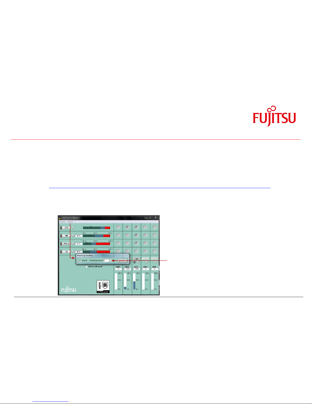
o For easy testing, the SystemGuard tool provides access to the OS Watchdog. After enabling the Watchdog, SystemGuard retriggers the WD
continuously. In case the system freezes, SystemGuard does no longer provide the retrigger signal and the watchdog resets the system after the timeout.
Note: When SystemGuard is closed, the WD is stopped in order to avoid a unwanted system reset!
Menu “Special”:
--> Enable WD
--> Set timeout to 1 – 8 minutes
Page 54

a
Miscellaneous
10.2 BIOS Update / BIOS Recovery
BIOS update options
Link to related BIOS files (OEM FTP Server):
ftp://ftp.ts.fujitsu.com/pub/Mainboard-OEM-Sales/Products/Mainboards/Industrial&ExtendedLifetime/D3071-S_D3076-S/BIOS_D3071-S/
ftp://ftp.ts.fujitsu.com/pub/Mainboard-OEM-Sales/Products/Mainboards/Industrial&ExtendedLifetime/D3071-S_D3076-S/BIOS_D3076-S/
DOS-based BIOS update (DOS-bootable USB stick)
Required BIOS files:
o EfiFlash.exe (DOS flash tool)
o DosFlash.bat (batch file)
o D307x-S1.upd (flash file)
Copy unzipped files to a DOS-bootable USB stick, boot system from stick and run
DosFlash.bat
Links to bootable Free-DOS images to create a bootable USB stick:
24MB: http://support.ts.fujitsu.com/Download/ShowDescription.asp?SoftwareGUID=35ac1143-a178-4609-82f2-8bd3a5d2f23d
64MB: http://support.ts.fujitsu.com/Download/ShowDescription.asp?SoftwareGUID=6d835be5-24d0-482b-bbb0-1a3f125e808e
128MB: http://support.ts.fujitsu.com/Download/ShowDescription.asp?SoftwareGUID=3514c169-ac85-44f5-a858-08bdcb38df0e
256MB: http://support.ts.fujitsu.com/Download/ShowDescription.asp?SoftwareGUID=c409d7f4-2494-417f-82ed-395dc850de4d
512MB: http://support.ts.fujitsu.com/Download/ShowDescription.asp?SoftwareGUID=ad35b93d-46f9-4c6a-98ed-7116b86344ff
1GB: http://support.ts.fujitsu.com/Download/ShowDescription.asp?SoftwareGUID=847bbc67-b135-4a95-a173-00cb0c4ecc27
2GB: http://support.ts.fujitsu.com/Download/ShowDescription.asp?SoftwareGUID=c95bc7d7-6fa1-4178-8a61-f55f4bc30706
4GB: http://support.ts.fujitsu.com/Download/ShowDescription.asp?SoftwareGUID=d0ee4c75-14fa-4bdc-a436-099901860e8f
Page 55

a
Miscellaneous
BIOS Update / BIOS Recovery
Windows-based BIOS update (Deskflash tool)
Required BIOS file:
o D307x-S1x.R1.x.y.DFI.exe (Windows executable flash tool)
Copy file from FTP (link see above), rename
filename.$xe
to
filename.exe
and copy to target system (e.g. Windows desktop).
Doubleclick to start BIOS update and follow instructions on the screen.
DOS-based BIOS Recovery (DOS-bootable USB stick)
Required BIOS files:
o EfiFlash.exe (DOS flash tool)
o DosFlash.bat (batch file)
o D307x-S1.upd (flash file)
o D307x-S1.rom --> Important: This file must be located in the root directory of the USB stick!
Set onboard jumper to Recovery Mode
Copy unzipped files to a DOS-bootable USB stick,
boot system from stick and run
DosFlash.bat
Follow instructions on the screen and set jumper to default position
Note:
BIOS Recovery should only be used to repair a corrupted BIOS.
All customized data except for OEM SLP data will be reset.
Page 56

a
54
Copyright 2011 FUJITSU
TechNotes D307x-S V1.1
 Loading...