

Page 1
Areas Covered
Before Reading This Manual
This section explains the notes for your safety and conventions used in this manual.
Chapter 1
Chapter 2 Checking before OS Installation
Chapter 3 OS Installation
Chapter 4 Operations after OS Installation
Chapter 5 High Reliability Tools
Chapter 6 Installing Internal Options
Overview
This chapter explains component names and basic operations of this server, as well as an
overview of the software provided with this server. In addition, the workflow, from placing the
server to starting the operation, is also described.
This chapter explains the preparation and cautions for the server before OS installation. Observe
this chapter before starting installation.
This chapter explains how to install the OS in the server using ServerStart.
This chapter explains the operations to be performed after OS installation. Be sure to perform
these operations before operating the server.
For stable PRIMERGY server operations, we recommend that high reliability tools be installed.
This chapter explains the installation and necessary settings of high reliability tools.
This chapter explains how to install and remove the various hardware options.
PRIMERGY TX150 S6 User’s Guide
Chapter 7 Configuring Hardware and Utilities
This chapter explains how to make the environment settings necessary to operate the server and
how to use each utility.
Chapter 8 Operation and Maintenance
This chapter explains the operations that become necessary after starting to use this server as well
as daily care and maintenance.
Appendix
This appendix explains the specifications for the server and for its internal options.
1
Page 2
Before Reading This Manual
For Your Safety...
This manual contains important information, required to operate the server safely.
Thoroughly review the information in this manual before using the server. Especially note the points under "Safety Precautions", and only
operate the server with a complete understanding of the material provided.
This manual and "Safety Precautions" should be kept in an easy-to-access location for quick reference when using this server.
Data Backup
To protect data stored in this device (including basic software and application software), perform backup and other necessary operations.
Note that data protection is not guaranteed when repairs are performed. It is the customer's responsibility to maintain backup copies in
advance.
In case of data loss, Fujitsu assumes no liability for data maintenance or restoration and damages that occur as a result of the data loss for any
reason, except for items covered under warranty.
High Safety
The Products are designed, developed and manufactured as contemplated or general use, including without limitation, general office use,
personal use, household use, and ordinary industrial use, but are not designed, developed and manufactured as contemplated for use
accompanying fatal risks or dangers that, unless extremely high safety is secured, could lead directly to death, personal injury, severe physical
damage, or other loss (hereinafter "High Safety Required Use"), including without limitation, nuclear reaction control in nuclear facility,
aircraft flight control, air traffic control, mass transport control, medical life support system, missile launch control in weapon system. You
shall not use this Product without securing the sufficient safety required for the High Safety Required Use. If you wish to use this Product for
High Safety Required Use, please consult with our sales representatives in charge before such use.
Problems may occur with this device in the event of an instantaneous voltage drop of the power supply due to lightning, etc. To prevent an
instantaneous voltage drop of the power supply, we recommend that you use an uninterruptible power supply system.
SATA hard disk unit (SATA model)
The SATA hard disk that is installed in the SATA model is designed to be used about eight hours per
day for five years with small scale and comparatively low access frequency.
Refrain from using for mission-critical tasks in which continuous 24/7/365 operation is necessary, or
database in which the access is frequently repeated, and high reliability is required.
To prevent the loss of important data, regular data backup is recommended.
Trademarks
Microsoft, Windows, and Windows Server are trademarks or registered trademarks of Microsoft Corporation in the USA
and other countries.
Intel, Xeon are registered trademarks or trademarks of Intel Corporation or its subsidiaries in the USA and other
countries.
Linux is a trademark or registered trademark of Linus Torvalds in the USA and other countries.
Red Hat and all Red Hat-based trademarks and logos are trademarks or registered trademarks of Red Hat, Inc. in the
USA and other countries.
Other product names used are trademarks or registered trademarks of their respective manufacturers.
Other products are copyrights of their respective manufacturers.
All Rights Reserved, Copyright© FUJITSU LIMITED 2008
Screen shot(s) reprinted with permission from Microsoft Corporation.
2
Page 3
PRIMERGY TX150 S6 User’s Guide
Remarks
Warning descriptions
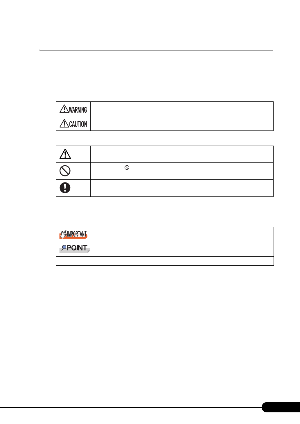
Various symbols are used throughout this manual. These are used to emphasize important points for
your safety and that of others. The following are the symbols and their meanings. Fully understand these
symbols when reading this manual.
Failure to observe this warning may cause serious injury or death, and/or destroy the system.
Failure to observe this warning may lead to injury, destruction of the system, or loss of data.
The following symbols are used to indicate the type of warning or caution being described.
A triangle mark emphasizes the urgency of the WARNING and CAUTION. Details are
described next to the triangle.
A barred circle ( ) warns against certain actions (Do Not). Details are described next to the
circle.
A black circle indicates actions that must be taken. Details are described next to the black
circle.
Symbols
Symbols used in this manual have the following meanings.
These sections explain prohibited actions and points to note when using this device. Make
sure to read these sections.
These sections explain information needed to operate the hardware and software properly.
Make sure to read these sections.
→
This mark indicates reference pages or manuals.
Key descriptions / operations
Keys are represented throughout this manual in the following manner.
E.g.: [Ctrl] key, [Enter] key, [→] key, etc.
The following indicate pressing several keys at once:
E.g.: [Ctrl] + [F3] key, [Shift] + [↑] key, etc.
DVD-ROM drive description
DVD-ROM drive is described as "CD/DVD drive" herein.
3
Page 4
Entering commands (Keys)
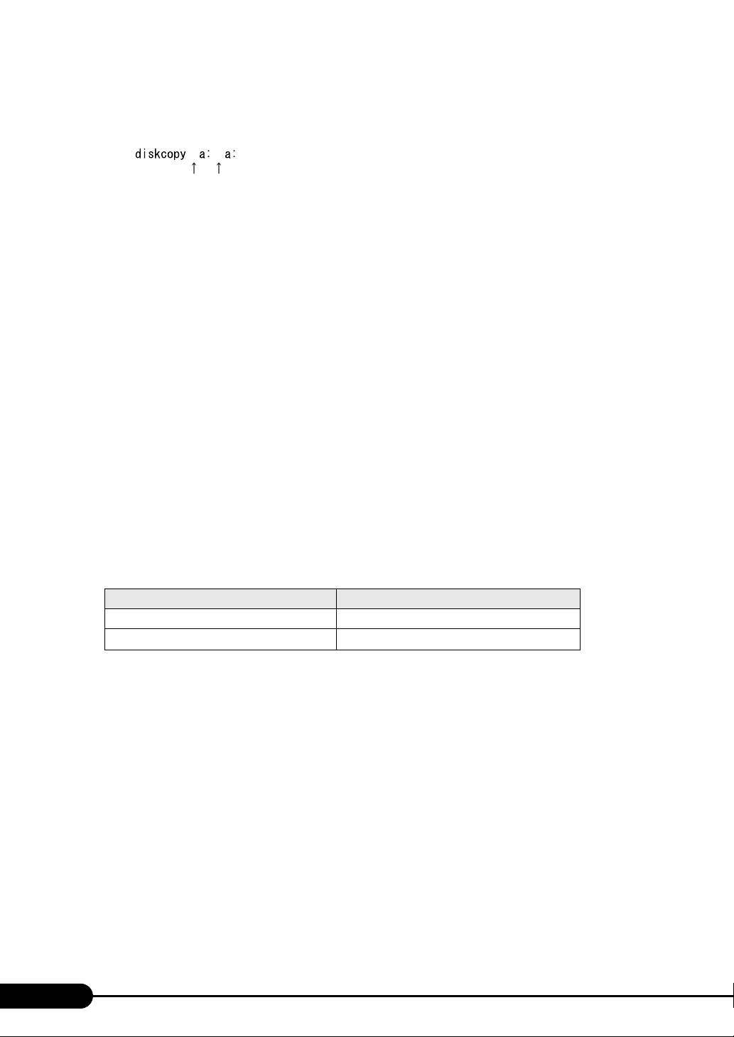
Command entries are displayed in the following way.
• At each blank in a command line (as pointed out above), press the [Space] key once.
• When using Windows or DOS OS, commands are not case sensitive.
• CD/DVD drive names are shown as [CD/DVD drive]. Enter your drive name according to your
environment.
[CD/DVD drive]:\setup.exe
Screen shots and figures
Screen shots and figures are used as visual aids throughout this manual. Windows, screens, and file
names may vary depending on the OS, software, or configuration of the server used. Figures in this
manual may not show cables that are actually connected for convenience of explanation.
Consecutive operations
Consecutive operations are described by connecting them with "–".
Example: Procedure of clicking the [Start] button, pointing to [Programs], and clicking [Accessories]
↓
Click [Start]
– [Programs] – [Accessories].
Server types
Server types are described as follows.
Type Expressions and abbreviations
Servers without an internal hard disk Diskless type
Server installed on a rack
table: Server Types
Rack type
4
Page 5
Abbreviations
The following expressions and abbreviations are used throughout this manual.
table: Abbreviations of Product names
Product name Expressions and abbreviations
PRIMERGY TX150 S6 (SAS model) SAS model TX150 S6 or the server
PRIMERGY TX150 S6 (SATA model) SATA model
®
Microsoft
Windows Server® 2003 R2, Standard
Edition
Microsoft
®
Windows Server® 2003, Standard
Edition
Microsoft
®
Windows Server® 2003, Standard x64
Edition
Microsoft® Windows Server® 2003 R2, Standard
x64 Edition
®
Microsoft
Windows® Small Business Server 2003 SBS 2003
Microsoft® Windows® Small Business Server 2003
R2
®
Microsoft
Microsoft
Microsoft
Microsoft
Microsoft
Microsoft
Microsoft
Windows® 2000 Server
®
Windows® Preinstallation Environment
®
Windows Vista® Business
®
Windows® XP Professional
®
Windows® 2000 Professional
®
Windows Server® 2003 Service Pack
®
Windows Server® 2003 x64
Service Pack
Red Hat Enterprise Linux ES (v.4 for x86) Linux
Red Hat Enterprise Linux ES (v.4 for EM64T)
Red Hat Enterprise Linux 5 (for x86)
Red Hat Enterprise Linux 5 (for Intel64)
Windows Server 2003 R2 Windows
Windows Server 2003,
Standard Edition
Windows Server 2003 x64
Windows Server 2003 R2 x64
*1
SBS 2003 R2
Windows 2000 Server
Windows PE
Windows Vista
Windows XP Professional
Windows 2000 Professional
Service Pack
PRIMERGY TX150 S6 User’s Guide
Windows
Server
2003
*1
*1: Unless otherwise noted, Windows Server 2003 can also mean SBS 2003 and Windows 2003 x64.
5
Page 6
SATA
model
SAS
model
䇭䇭㸡
䈬䈤䉌䈎
䇭䇭㸣
PRIMERGY TX150 S6 model descriptions
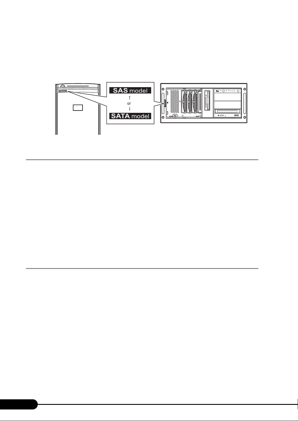
PRIMERGY TX150 S6 has SAS model and SATA model. Herein, unless otherwise noted, these
descriptions apply to both models. For descriptions unique to a given model, a model name is cited.
Before reading this manual, check the "model label" attached to the following location on each server.
䌛Rack Type䌝
SAS
model
䇭䇭㸡
䈬䈤䉌䈎
䇭䇭㸣
SATA
model
Reference Information
Software manuals
Software Manual contains other reference information and cautions for ServerStart not described in this
manual. Please read it before using ServerStart.
Software Manual is contained as a "README.TXT" file in the root directory on PRIMERGY Startup
Disc. Use a text editor to read it.
Latest information about software provided with this server
For the latest information regarding ServerStart and other software provided with this server, refer to the
Fujitsu PRIMERGY website (http://primergy.fujitsu.com).
Warning and Caution Labels
Warning and caution labels are found on the server.
Do not remove or stain these labels.
6
Page 7
Contents
Chapter 1 Overview
1.1 TX150 S6 . . . . . . . . . . . . . . . . . . . . . . . . . . . . . . . . . . . . . . . . . . . . 14
1.2 Supplied Software . . . . . . . . . . . . . . . . . . . . . . . . . . . . . . . . . . . . 16
1.2.1 Setup Support Tool - ServerStart . . . . . . . . . . . . . . . . . . . . . . . . . . . . . . . .16
1.2.2 High Reliability Tools . . . . . . . . . . . . . . . . . . . . . . . . . . . . . . . . . . . . . . . . . 19
1.2.3 Installing High Reliability Tools . . . . . . . . . . . . . . . . . . . . . . . . . . . . . . . . . . 20
1.3 Component Names and Functions . . . . . . . . . . . . . . . . . . . . . . . 22
1.3.1 Server (front view) . . . . . . . . . . . . . . . . . . . . . . . . . . . . . . . . . . . . . . . . . . .22
1.3.2 Server (rear view) . . . . . . . . . . . . . . . . . . . . . . . . . . . . . . . . . . . . . . . . . . . . 25
1.3.3 Server (internal) . . . . . . . . . . . . . . . . . . . . . . . . . . . . . . . . . . . . . . . . . . . . .27
1.3.4 Baseboard . . . . . . . . . . . . . . . . . . . . . . . . . . . . . . . . . . . . . . . . . . . . . . . . .28
1.4 Standard Operations . . . . . . . . . . . . . . . . . . . . . . . . . . . . . . . . . . 30
1.4.1 Sliding the Drive Cover . . . . . . . . . . . . . . . . . . . . . . . . . . . . . . . . . . . . . . . 30
1.4.2 Opening the Rack Door . . . . . . . . . . . . . . . . . . . . . . . . . . . . . . . . . . . . . . . 31
1.4.3 Turning On the Server . . . . . . . . . . . . . . . . . . . . . . . . . . . . . . . . . . . . . . . .33
1.4.4 Turning Off the Server . . . . . . . . . . . . . . . . . . . . . . . . . . . . . . . . . . . . . . . .34
1.4.5 Inserting and Ejecting a Floppy Disk . . . . . . . . . . . . . . . . . . . . . . . . . . . . .36
1.4.6 Inserting and Ejecting a CD/DVD . . . . . . . . . . . . . . . . . . . . . . . . . . . . . . . .38
1.5 Workflow . . . . . . . . . . . . . . . . . . . . . . . . . . . . . . . . . . . . . . . . . . . . 40
PRIMERGY TX150 S6 User’s Guide
Chapter 2 Checking before OS Installation
2.1 Preparation on the Server . . . . . . . . . . . . . . . . . . . . . . . . . . . . . . 42
2.1.1 Installing Internal Options . . . . . . . . . . . . . . . . . . . . . . . . . . . . . . . . . . . . . .42
2.1.2 Hardware Settings . . . . . . . . . . . . . . . . . . . . . . . . . . . . . . . . . . . . . . . . . . .44
2.2 Selecting an Installation Method . . . . . . . . . . . . . . . . . . . . . . . . 45
2.2.1 Supported OS . . . . . . . . . . . . . . . . . . . . . . . . . . . . . . . . . . . . . . . . . . . . . . .45
2.2.2 Installation Modes of ServerStart . . . . . . . . . . . . . . . . . . . . . . . . . . . . . . . .45
2.3 Precautions on Installation . . . . . . . . . . . . . . . . . . . . . . . . . . . . . 46
2.3.1 Installation Partition Size . . . . . . . . . . . . . . . . . . . . . . . . . . . . . . . . . . . . . . 46
2.3.2 Notes on Configuring RAID . . . . . . . . . . . . . . . . . . . . . . . . . . . . . . . . . . . .46
2.3.3 Cautions for Using ServerStart . . . . . . . . . . . . . . . . . . . . . . . . . . . . . . . . . 47
2.3.4 Automatic Driver Installation with ServerStart . . . . . . . . . . . . . . . . . . . . . . 49
Chapter 3 OS Installation
3.1 Quick Installation Mode . . . . . . . . . . . . . . . . . . . . . . . . . . . . . . . . 52
3.2 Expert Mode . . . . . . . . . . . . . . . . . . . . . . . . . . . . . . . . . . . . . . . . . 58
3.2.1 Starting Up the Expert Mode . . . . . . . . . . . . . . . . . . . . . . . . . . . . . . . . . . .58
3.2.2 Disk Manager . . . . . . . . . . . . . . . . . . . . . . . . . . . . . . . . . . . . . . . . . . . . . . .62
3.2.3 OS Installation Wizard . . . . . . . . . . . . . . . . . . . . . . . . . . . . . . . . . . . . . . . .63
7
Page 8
3.2.4 Application Wizard . . . . . . . . . . . . . . . . . . . . . . . . . . . . . . . . . . . . . . . . . . . 68
3.2.5 Starting OS Installation . . . . . . . . . . . . . . . . . . . . . . . . . . . . . . . . . . . . . . . 69
Chapter 4 Operations after OS Installation
4.1 Memory Dump/Paging File Setting . . . . . . . . . . . . . . . . . . . . . . . 74
4.1.1 How to Obtain Memory Dump . . . . . . . . . . . . . . . . . . . . . . . . . . . . . . . . . . 74
4.2 Creating a Disk for System Recovery . . . . . . . . . . . . . . . . . . . . . 79
4.2.1 Creating the Automated System Recovery (ASR) Set . . . . . . . . . . . . . . . 79
4.3 Storing the System Configuration Information . . . . . . . . . . . . . 81
4.3.1 Storing the BIOS Information and the Remote Management Controller
Information . . . . . . . . . . . . . . . . . . . . . . . . . . . . . . . . . . . . . . . . . . . . . . . 82
4.3.2 Recovering the BIOS / Remote Management Information . . . . . . . . . . . 83
4.4 Creating Maintenance Tools and Driver Disks . . . . . . . . . . . . . 85
4.4.1 Installing ServerStart . . . . . . . . . . . . . . . . . . . . . . . . . . . . . . . . . . . . . . . . . 85
4.4.2 Startup Method for FloppyBuilder . . . . . . . . . . . . . . . . . . . . . . . . . . . . . . . 88
4.4.3 Creating Server Management Tools Disk . . . . . . . . . . . . . . . . . . . . . . . . . 90
4.4.4 Creating Driver Disks . . . . . . . . . . . . . . . . . . . . . . . . . . . . . . . . . . . . . . . . . 91
4.4.5 Creating a DOS Diskette . . . . . . . . . . . . . . . . . . . . . . . . . . . . . . . . . . . . . . 91
4.5 Notes before Operating the Server . . . . . . . . . . . . . . . . . . . . . . . 92
4.5.1 Auto-run Function from CD/DVD Drives . . . . . . . . . . . . . . . . . . . . . . . . . . 92
4.5.2 Drive Letter Assignment in the Expert Mode . . . . . . . . . . . . . . . . . . . . . . . 92
4.5.3 Notes on Advanced Uninterruptible Power Supply (UPS) . . . . . . . . . . . . 93
4.5.4 Turning the Power On via a LAN . . . . . . . . . . . . . . . . . . . . . . . . . . . . . . . . 94
4.5.5 Other Notes on Operation . . . . . . . . . . . . . . . . . . . . . . . . . . . . . . . . . . . . . 94
4.6 LAN Driver Advanced Setup [BACS] . . . . . . . . . . . . . . . . . . . . . 95
4.6.1 BACS Installation . . . . . . . . . . . . . . . . . . . . . . . . . . . . . . . . . . . . . . . . . . . . 95
4.7 LAN Driver Advanced Setup [Intel® PROSet] . . . . . . . . . . . . . . 98
4.7.1 Intel® PROSet Installation . . . . . . . . . . . . . . . . . . . . . . . . . . . . . . . . . . . . . 98
4.7.2 Cautions for PG-185x/186x/188x/189x/286x LAN Driver V11.2 . . . . . . . . 99
4.7.3 Teaming Function . . . . . . . . . . . . . . . . . . . . . . . . . . . . . . . . . . . . . . . . . . . 99
4.7.4 VLAN . . . . . . . . . . . . . . . . . . . . . . . . . . . . . . . . . . . . . . . . . . . . . . . . . . . . 101
Chapter 5 High Reliability Tools
5.1 RAID Management Tool . . . . . . . . . . . . . . . . . . . . . . . . . . . . . . . 104
5.2 Server Monitoring Tool [ServerView] . . . . . . . . . . . . . . . . . . . . 105
5.2.1 Installing ServerView . . . . . . . . . . . . . . . . . . . . . . . . . . . . . . . . . . . . . . . . 106
5.2.2 Setting Required after Installation . . . . . . . . . . . . . . . . . . . . . . . . . . . . . . 107
5.3 Maintenance Support Tool [HRM/Server] . . . . . . . . . . . . . . . . 108
5.3.1 Installing HRM/Server . . . . . . . . . . . . . . . . . . . . . . . . . . . . . . . . . . . . . . . 108
5.3.2 How to Use . . . . . . . . . . . . . . . . . . . . . . . . . . . . . . . . . . . . . . . . . . . . . . . 108
5.4 Solving Problems Early [DSNAP] . . . . . . . . . . . . . . . . . . . . . . . 109
5.4.1 Installing DSNAP . . . . . . . . . . . . . . . . . . . . . . . . . . . . . . . . . . . . . . . . . . . 109
5.4.2 How to Use . . . . . . . . . . . . . . . . . . . . . . . . . . . . . . . . . . . . . . . . . . . . . . . 109
8
Page 9
Chapter 6 Installing Internal Options
6.1 Before Installing Internal Options . . . . . . . . . . . . . . . . . . . . . . . 112
6.2 Removing and Attaching Covers . . . . . . . . . . . . . . . . . . . . . . . 114
6.2.1 Removing Covers . . . . . . . . . . . . . . . . . . . . . . . . . . . . . . . . . . . . . . . . . . . 114
6.2.2 Removing the Top Cover of the Rack Type . . . . . . . . . . . . . . . . . . . . . . . 116
6.3 Installing Memory Modules . . . . . . . . . . . . . . . . . . . . . . . . . . . . 118
6.3.1 Installation Locations of Memory Modules . . . . . . . . . . . . . . . . . . . . . . . . 119
6.3.2 Installable Memory Modules and Notes . . . . . . . . . . . . . . . . . . . . . . . . . . 119
6.3.3 How to Install and Remove Memory Modules . . . . . . . . . . . . . . . . . . . . .120
6.3.4 Defective Memory Disconnection Function . . . . . . . . . . . . . . . . . . . . . . .121
6.4 Installing Expansion Cards . . . . . . . . . . . . . . . . . . . . . . . . . . . . 122
6.4.1 Installation Location of Expansion Cards . . . . . . . . . . . . . . . . . . . . . . . . .122
6.4.2 Installable Expansion Cards and Notes . . . . . . . . . . . . . . . . . . . . . . . . . .123
6.4.3 How to Install Expansion Cards . . . . . . . . . . . . . . . . . . . . . . . . . . . . . . . .124
6.4.4 Installing a Battery Backup Unit . . . . . . . . . . . . . . . . . . . . . . . . . . . . . . . . 126
6.4.5 When a SAS array controller is Installed for SATA Model . . . . . . . . . . . . 128
6.5 Installing Internal Hard Disk Units . . . . . . . . . . . . . . . . . . . . . . 130
6.5.1 Installation Locations of Internal Hard Disk Units . . . . . . . . . . . . . . . . . .131
6.5.2 Installable Internal Hard Disk Units and Notes . . . . . . . . . . . . . . . . . . . .131
6.5.3 How to Install the Internal Hard Disk Unit . . . . . . . . . . . . . . . . . . . . . . . .132
6.5.4 How to Remove the Internal Hard Disk Unit . . . . . . . . . . . . . . . . . . . . . .134
6.6 Installing 5-inch Internal Options . . . . . . . . . . . . . . . . . . . . . . . 135
6.6.1 Installation Location of 5-inch Internal Devices . . . . . . . . . . . . . . . . . . . .135
6.6.2 Installable 5-inch Internal Devices . . . . . . . . . . . . . . . . . . . . . . . . . . . . . 136
6.6.3 How to Install a 5-inch Internal Device . . . . . . . . . . . . . . . . . . . . . . . . . . .136
6.7 Installing a Parallel Port Option . . . . . . . . . . . . . . . . . . . . . . . . 139
6.7.1 How to Install a Parallel Port . . . . . . . . . . . . . . . . . . . . . . . . . . . . . . . . . .139
6.8 Installing an Optional Serial Port . . . . . . . . . . . . . . . . . . . . . . . 143
6.8.1 Where to Install an Optional Serial Port . . . . . . . . . . . . . . . . . . . . . . . . . . 143
6.8.2 How to Install an Optional Serial Port . . . . . . . . . . . . . . . . . . . . . . . . . . .144
6.9 Connecting External SCSI Devices . . . . . . . . . . . . . . . . . . . . . . 146
PRIMERGY TX150 S6 User’s Guide
Chapter 7 Configuring Hardware and Utilities
7.1 Jumper Settings . . . . . . . . . . . . . . . . . . . . . . . . . . . . . . . . . . . . . 148
7.1.1 Jumper Location and Settings . . . . . . . . . . . . . . . . . . . . . . . . . . . . . . . . . 148
7.2 BIOS Setup Utility . . . . . . . . . . . . . . . . . . . . . . . . . . . . . . . . . . . . 149
7.2.1 Starting and Exiting BIOS Setup Utility . . . . . . . . . . . . . . . . . . . . . . . . . .149
7.2.2 Main Menu . . . . . . . . . . . . . . . . . . . . . . . . . . . . . . . . . . . . . . . . . . . . . . . .152
7.2.3 Boot Features Submenu . . . . . . . . . . . . . . . . . . . . . . . . . . . . . . . . . . . . .153
7.2.4 Advanced Menu . . . . . . . . . . . . . . . . . . . . . . . . . . . . . . . . . . . . . . . . . . . .154
7.2.5 Peripheral Configuration Submenu . . . . . . . . . . . . . . . . . . . . . . . . . . . . .155
7.2.6 Advanced System Configuration Submenu . . . . . . . . . . . . . . . . . . . . . . . 157
9
Page 10
7.2.7 Advanced Processor Options Submenu . . . . . . . . . . . . . . . . . . . . . . . . . 158
7.2.8 PCI Configuration Submenu . . . . . . . . . . . . . . . . . . . . . . . . . . . . . . . . . . 159
7.2.9 Security Menu . . . . . . . . . . . . . . . . . . . . . . . . . . . . . . . . . . . . . . . . . . . . . 160
7.2.10 Power Menu . . . . . . . . . . . . . . . . . . . . . . . . . . . . . . . . . . . . . . . . . . . . . 162
7.2.11 Server Menu . . . . . . . . . . . . . . . . . . . . . . . . . . . . . . . . . . . . . . . . . . . . . 163
7.2.12 CPU Status Submenu . . . . . . . . . . . . . . . . . . . . . . . . . . . . . . . . . . . . . . 164
7.2.13 Memory Status Submenu . . . . . . . . . . . . . . . . . . . . . . . . . . . . . . . . . . . 165
7.2.14 PCI Status Submenu . . . . . . . . . . . . . . . . . . . . . . . . . . . . . . . . . . . . . . . 165
7.2.15 Console Redirection Submenu . . . . . . . . . . . . . . . . . . . . . . . . . . . . . . . 166
7.2.16 IPMI Submenu . . . . . . . . . . . . . . . . . . . . . . . . . . . . . . . . . . . . . . . . . . . . 167
7.2.17 Boot Menu . . . . . . . . . . . . . . . . . . . . . . . . . . . . . . . . . . . . . . . . . . . . . . 168
7.2.18 Exit Menu . . . . . . . . . . . . . . . . . . . . . . . . . . . . . . . . . . . . . . . . . . . . . . . . 169
Chapter 8 Operation and Maintenance
8.1 Daily Maintenance . . . . . . . . . . . . . . . . . . . . . . . . . . . . . . . . . . . 172
8.1.1 Checking the Server Status . . . . . . . . . . . . . . . . . . . . . . . . . . . . . . . . . . . 172
8.1.2 Cleaning . . . . . . . . . . . . . . . . . . . . . . . . . . . . . . . . . . . . . . . . . . . . . . . . . . 172
8.1.3 Replacement of Consumable Items . . . . . . . . . . . . . . . . . . . . . . . . . . . . 175
8.2 Troubleshooting . . . . . . . . . . . . . . . . . . . . . . . . . . . . . . . . . . . . . 176
8.2.1 Hardware Troubleshooting . . . . . . . . . . . . . . . . . . . . . . . . . . . . . . . . . . . 176
8.2.2 Error Messages . . . . . . . . . . . . . . . . . . . . . . . . . . . . . . . . . . . . . . . . . . . . 178
8.2.3 Software Troubleshooting . . . . . . . . . . . . . . . . . . . . . . . . . . . . . . . . . . . . 185
8.3 System Event Log . . . . . . . . . . . . . . . . . . . . . . . . . . . . . . . . . . . . 190
8.3.1 How to Refer to Event Logs . . . . . . . . . . . . . . . . . . . . . . . . . . . . . . . . . . 190
8.3.2 Deleting the System Event Log . . . . . . . . . . . . . . . . . . . . . . . . . . . . . . . . 190
8.4 Security . . . . . . . . . . . . . . . . . . . . . . . . . . . . . . . . . . . . . . . . . . . . 191
8.4.1 Hardware Security . . . . . . . . . . . . . . . . . . . . . . . . . . . . . . . . . . . . . . . . . . 191
8.4.2 Security against Unauthorized Use . . . . . . . . . . . . . . . . . . . . . . . . . . . . . 192
8.4.3 Security When Disposing of the Server . . . . . . . . . . . . . . . . . . . . . . . . . 194
8.5 Backup . . . . . . . . . . . . . . . . . . . . . . . . . . . . . . . . . . . . . . . . . . . . . 195
8.5.1 Importance of Backups . . . . . . . . . . . . . . . . . . . . . . . . . . . . . . . . . . . . . . 195
8.5.2 Backup Devices, Software and Their Operations . . . . . . . . . . . . . . . . . . 195
8.6 Restoring the System . . . . . . . . . . . . . . . . . . . . . . . . . . . . . . . . . 198
8.6.1 For Windows Server 2003 . . . . . . . . . . . . . . . . . . . . . . . . . . . . . . . . . . . 198
8.7 Reinstalling the OS . . . . . . . . . . . . . . . . . . . . . . . . . . . . . . . . . . . 200
8.7.1 Checking before OS Reinstallation . . . . . . . . . . . . . . . . . . . . . . . . . . . . . 200
8.7.2 Reinstallation Using ServerStart Floppy Disk . . . . . . . . . . . . . . . . . . . . . 200
8.8 Maintenance Service . . . . . . . . . . . . . . . . . . . . . . . . . . . . . . . . . 201
8.8.1 Contacting Maintenance Support . . . . . . . . . . . . . . . . . . . . . . . . . . . . . . 201
10
Page 11
Appendix
PRIMERGY TX150 S6 User’s Guide
A Server Specifications . . . . . . . . . . . . . . . . . . . . . . . . . . . . . . . . 204
A.1 SAS Model . . . . . . . . . . . . . . . . . . . . . . . . . . . . . . . . . . . . . . . . . . . . . . . . .204
A.2 SATA Model . . . . . . . . . . . . . . . . . . . . . . . . . . . . . . . . . . . . . . . . . . . . . . . .206
B Specifications for Internal Options . . . . . . . . . . . . . . . . . . . . . 208
B.1 Memory . . . . . . . . . . . . . . . . . . . . . . . . . . . . . . . . . . . . . . . . . . . . . . . . . . .208
B.2 Internal Hard Disk Units . . . . . . . . . . . . . . . . . . . . . . . . . . . . . . . . . . . . . . .209
B.3 Parallel Port Option . . . . . . . . . . . . . . . . . . . . . . . . . . . . . . . . . . . . . . . . . .210
B.4 Serial Port . . . . . . . . . . . . . . . . . . . . . . . . . . . . . . . . . . . . . . . . . . . . . . . . . .210
B.5 Power Cord Selection . . . . . . . . . . . . . . . . . . . . . . . . . . . . . . . . . . . . . . . . .210
C Remote Control Function . . . . . . . . . . . . . . . . . . . . . . . . . . . . . 213
C.1 Preparation for Using Remote Control Function . . . . . . . . . . . . . . . . . . . . 213
C.2 Remote Power Supply Control . . . . . . . . . . . . . . . . . . . . . . . . . . . . . . . . . .215
D Remote Management Controller . . . . . . . . . . . . . . . . . . . . . . . 218
D.1 Overview of the Remote Management Controller . . . . . . . . . . . . . . . . . . .218
D.2 Preparation for Using Remote Management Controller . . . . . . . . . . . . . . .219
D.3 Window of the Remote Management Controller . . . . . . . . . . . . . . . . . . . .220
D.4 Remote Management Ctrl Upgrade kit (PG-RMCU2) . . . . . . . . . . . . . . . .221
E Recycling . . . . . . . . . . . . . . . . . . . . . . . . . . . . . . . . . . . . . . . . . . 223
11
Page 12
12
Page 13
Chapter 1
Overview
This chapter explains component names and
basic operations of this server, as well as an
overview of the software provided with this
server. In addition, the workflow, from placing
the server to starting the operation, is also
described.
1.1 TX150 S6
1.2 Supplied Software
1.3 Component Names and Functions
1.4 Standard Operations
1.5 Workflow
. . . . . . . . . . . . . . . . . . . . . . . . . . . . . . . . . . . . 14
. . . . . . . . . . . . . . . . . . . . . . . . . . . . . . 16
. . . . . . . . . . . . . . . . . . . . . . . . . . . . 30
. . . . . . . . . . . . . . . . . . . . . . . . . . . . . . . . . . . . . 40
. . . . . . . . . . . . . . . . . . 22
13
Page 14

Chapter 1 Overview
1.1 TX150 S6
This server is an entry-level server with high-speed processing and costeffectiveness, having the following features.
High reliability
z Memory modules enabling high-speed processing
This server supports the memory module of DDR2-800 Unbuffered ECC DIMM, enabling high-speed
processing.
z Disk array configuration
For SAS model, array configuration can be made with an installed SAS controller card (Integrated
Mirroring SAS) or SAS array controller card (MegaRAID SAS) in standard.
For SATA model, array configuration can be made with Onboard Software RAID.
Depending on established array configurations, replacement and/or recovery of the hard disk unit(s) can
be performed as remaining the server and peripheral devices being turned on (available for hot plug,
except of RAID 0) when the server fails.
z Redundant function
Configured disk array systems (except of RAID 0) allow replacement and/or recovery of hard disk units
without turning off the server and peripheral devices when the hard disk in the server is failed (available
for hot plug).
z Hardware and software designed for data security
This server is designed to provide provisions for data securities to guard the hardware and data assets
with systems, such as locking a drive cover and setting a password in BIOS Setup Utility.
z Proactive fan function
Stable system operation is performed with automatically increasing the rotating speed of the system fan
to control temperature in the server as a fan fails or the ambient temperature rises.
z High reliability tools
High reliability tools, such as ServerView which is the tool for monitoring the server status, offer further
stable system operation. Refer to "1.2.2 High Reliability Tools" (pg.19) for details.
14
Page 15
High-speed processing
PRIMERGY TX150 S6 User’s Guide
z Intel
®
Xeon® Processor
An Intel® Xeon® Processor (dual core processor) is installed, which is capable to perform high-speed
data processing.
When using CPU Conversion kit, further high-speed performance can be obtained as a quad-core
processor is installed.
Excellent scalability
z Maximum 8GB memory size
In addition to the preinstalled 512MB memory, the memory is expandable up to 8GB.
z Four hard disk bays
Up to four internal hard disk units can be installed in 3.5-inch storage bays.
Hard disk units, maximum capacity of 300GB for SAS model and 500GB for SATA model, are
supported.
z Six PCI slots
The server has six PCI slots. Functions can be expanded with using expansion cards.
When SAS model is used
Up to five expandable PCI cards can be added since Slot 5 has been installed a SAS array controller
card as a standard feature.
z 5-inch internal option bay
The 5-inch options such as backup unit can be installed to accommodate for mounting data.
z Rack type
With attaching a Rack Conversion kit, the server can be installed on a rack.
15
Page 16
Chapter 1 Overview
1.2 Supplied Software
The following software is supplied together with the server. ServerStart supports
setting up the system and high reliability tools to prevent troubles while server system
is running.
1.2.1 Setup Support Tool - ServerStart
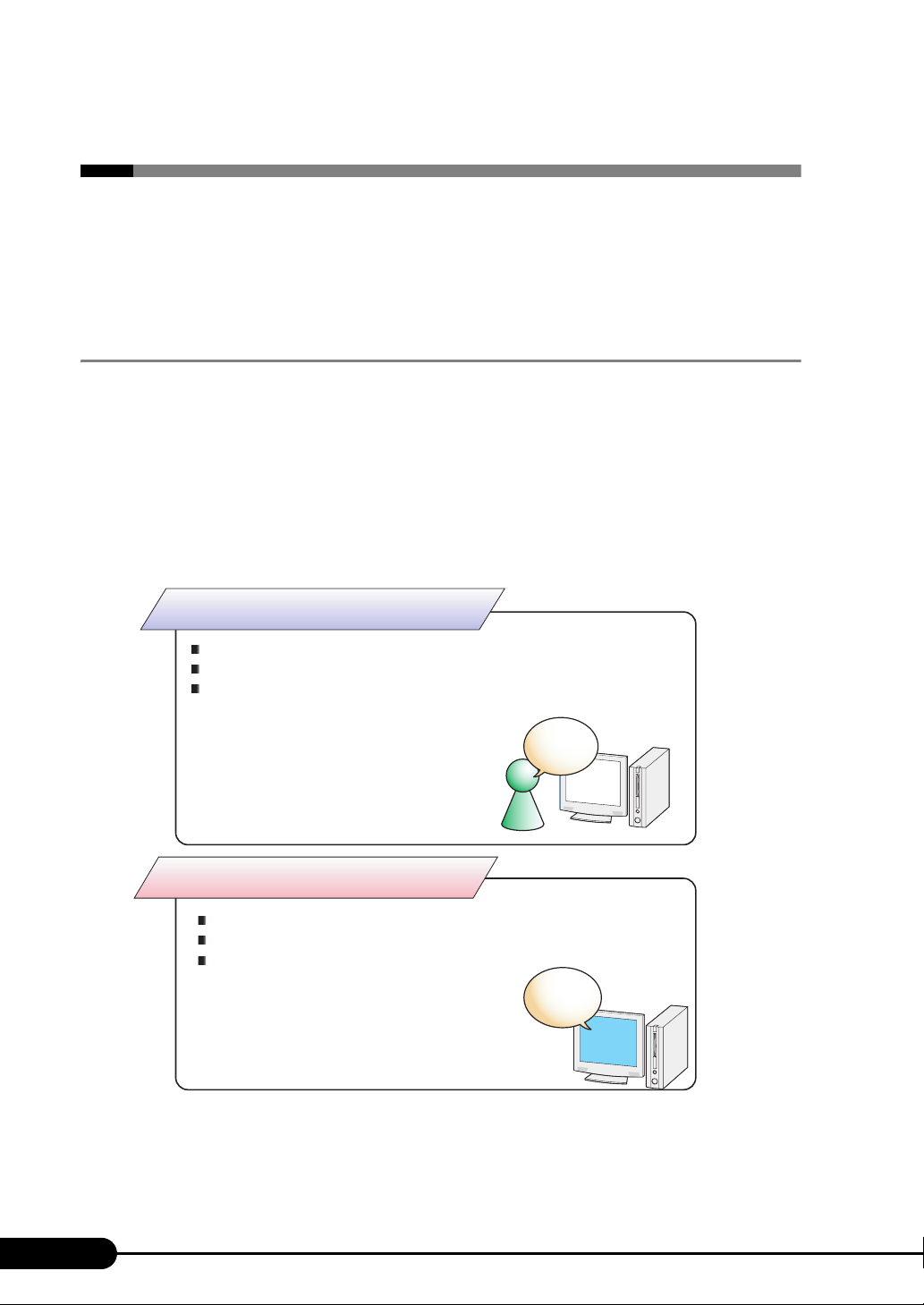
ServerStart is an initial setup support tool for PRIMERGY. It offers simple procedures for setup and
proper installation for recommended drivers.
Setting up with ServerStart
When performing the OS installation with ServerStart, drivers which are corresponding to the
automatically recognized expansion cards will be installed by ServerStart. In addition, high reliability
tools and array controller management tools are automatically installed. It prevents the related errors.
It is recommended to perform the OS installation with using ServerStart.
Not using ServerStart
Complicated hardware settings such as RAID configuration
User definition, access policies and network settings
Manual settings for each item
resulting in leading mistakes and taking time for server installation.
Install
&
Setup
Example:
IP address settings, creation of user,
registration of computer name, and etc.
Using ServerStart
Automatic RAID configuration
Automatic installation of recommended drivers
Automatic installation of high reliability tools
are available.
Example:
Automated operations such as OS installation.
Auto setup
ServerStart
16
Page 17
PRIMERGY TX150 S6 User’s Guide
Some operations such as a license window and media replacements are required to be performed
manually.
High reliability tools are software with comprehensive strength for stable system operation of the
server management.
Merit with ServerStart setup
z Network configuration
ServerStart can configure a network on server installation. For details on available network patterns,
refer to "Using ServerStart to Configure the Network".
z Automatic driver installation
This function installs the recommended drivers for such as automatically recognized expansion cards on
the server installation. It is preventative for mismatch driver installations, such as previous version or
incompatible drivers.
z Automatic RAID configuration
Without RAID utility, disk array can be configured by specifying a RAID type and number of hard disk
unit.
Intuitive user interface
The intuitive user interface allows you to easily set the necessary information.
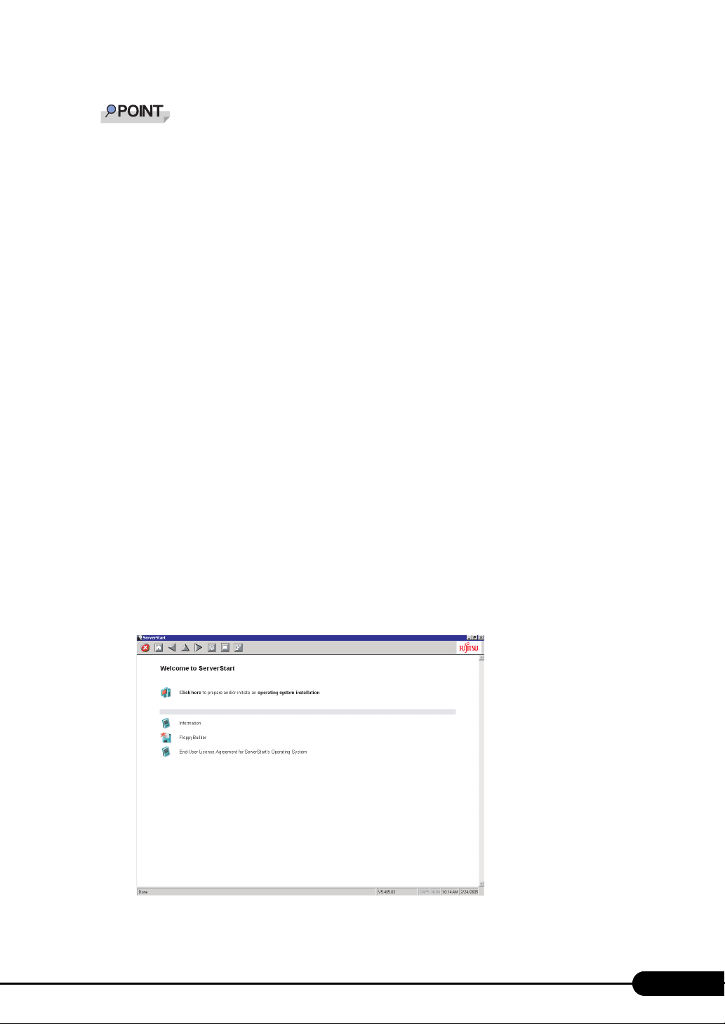
z Main window
When ServerStart starts up, the following window appears. The window and tool bar differ, depending
on the mode.
17
Page 18
Chapter 1 Overview
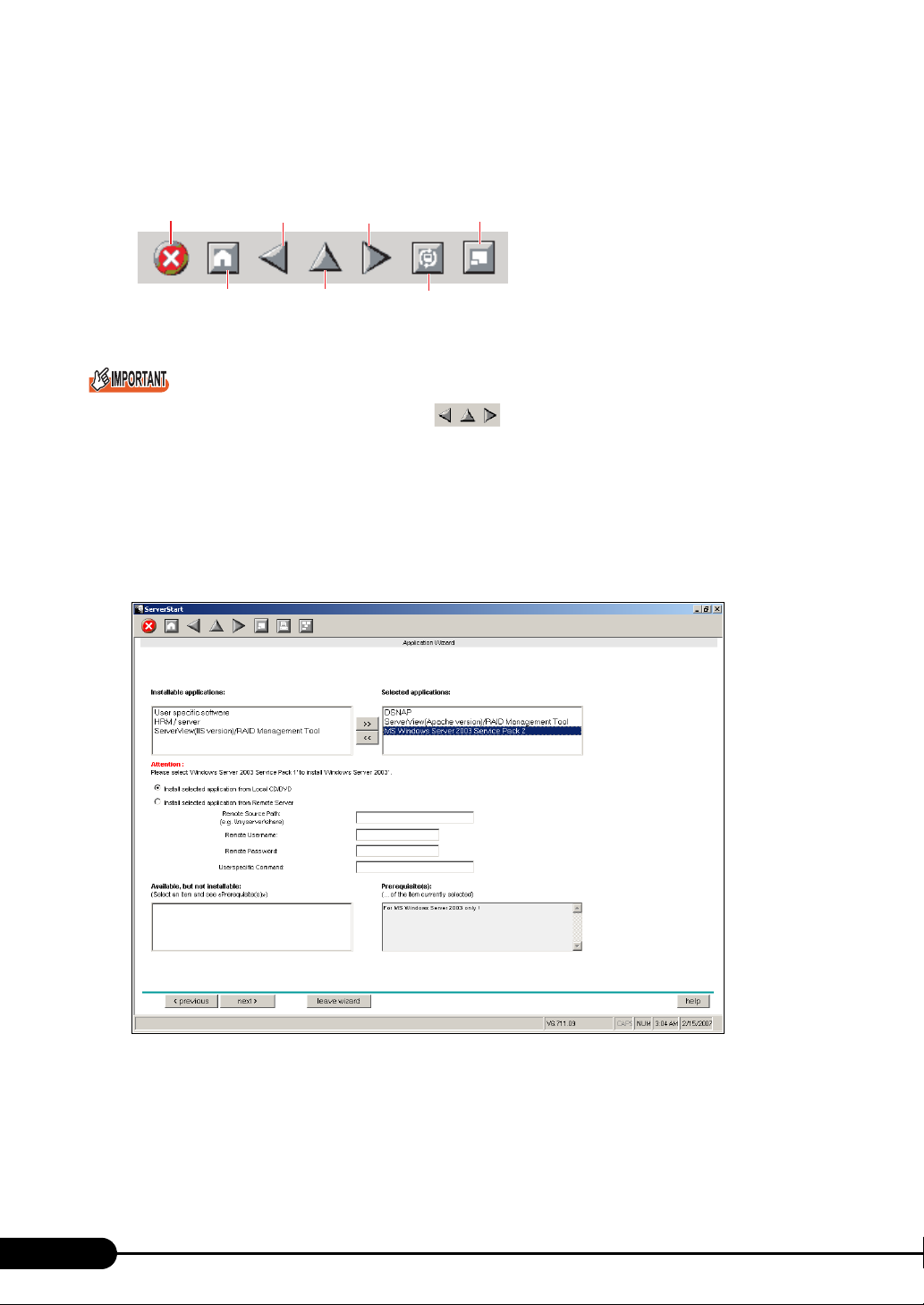
z Tool bar
For the expert mode
Ends ServerStart.
Returns to the
previous page.
Goes to the
next page.
Changes the size
of icons.
Returns to
the main screen.
Goes to one tier
upper.
Resets the status
function.
While the wizard is running, do not click the icon to move to the previous or next window or
to upper tree level. To move to a different window, click the [Previous], [Up], or [Next] button at the
bottom of the wizard window.
z Wizard window
Clicking a wizard displays a wizard window.
Set each item in the wizard window. To move to a step in the next wizard window, click the operation
button at the bottom of the window. Clicking [help] displays an explanation for setting the item.
18
Page 19
PRIMERGY TX150 S6 User’s Guide
1.2.2 High Reliability Tools
High reliability tools provide comprehensive supports for stable system operations of the server. The
following tools have individual management function through normal operations to restoration from
errors:
• Server monitoring tools
• System diagnosis support tools
• LAN driver advanced setup tools
Server monitoring tools
The server monitoring tools monitor the hardware status and notify the event of an error when irregular
status occurs.
z Early detection of a server failure [ServerView]
ServerView monitors the server status to protect important server resources. The server hardware keeps
under observation all the time and a potential irregular status will be notified in timely manner when it is
detected. A corrective action can be taken in early stage and eliminate the system error before growing a
serious matter.
For notes of security for ServerView, refer to " ● Security" in Section "1.1.7 Note", ServerView User’s
Guide.
z Maintenance support tool [HRM/server]
HRM/server performs the server maintenance operation promptly and surely to retain stable system
operation.
z Early detection of a disk problem [RAID Management Tool]
RAID Management Tool monitors a configured disk array performance. When an event occurs, it leaves
an event log in the event viewer's application logs. At the same time, a pop-up window indicates a hard
disk failure, rebuild status, etc.
System diagnosis support tools
The system diagnosis support tools boost device management in order to perform stable server
operation.
z Early solution to problems [DSNAP]
DSNAP is a command line utility for collectively acquiring failure analysis information. Command line
operation makes easy to set the configuration information of the system file and major registries, and
collect the event log. When a problem occurs in your Windows Server 2003 system, DSNAP is used for
a support engineer to understand your system software configuration and settings correctly and to
promote research smoothly. Provide this with memory dump to your support engineer.
19
Page 20
Chapter 1 Overview
LAN driver advanced setup Tools
These tools set details on the LAN, including the use of teaming (load balance) function and VLAN
configuration.
z Broadcom Advanced Control Suite (BACS)
BACS is a tool for setting details on the onboard LAN.
z Intel
®
PROSet
Intel® PROSet is a tool for setting details on the LAN card in case such as using teaming function
between LAN cards or onboard LAN and LAN card, and configuring a VLAN with LAN card.
1.2.3 Installing High Reliability Tools
Collective installation of all high reliability tools, provided with PRIMERGY, may be made by
specifying them in "Application Wizard".
The following high reliability tools are installed with ServerStart.
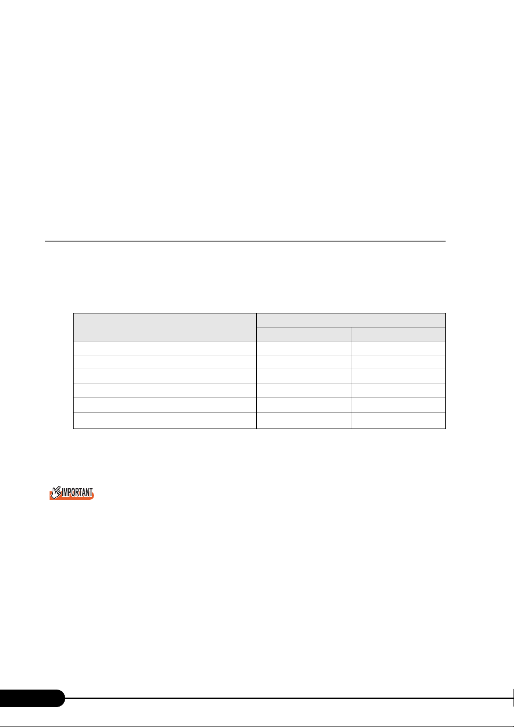
table: High reliability tools installation
High reliability tool
RAID Management Tool / ServerView (for Apache) I S
RAID Management Tool / ServerView (for IIS) M N
HRM/server I
DSNAP I S
Broadcom Advanced Control Suite (BACS) I
®
PROSet
Intel
I : Installed automatically
N: Installed if selected (Not selected by default)
S: Installed if selected (Selected by default)
M: Install manually.
Quick installation mode Expert mode
ServerStart installation
II
I
I
20
SBS 2003 and Linux do not support batch installation with ServerStart.
ServerView is required configuration after installation even when the high reliability tools have been
installed at once with ServerStart. Refer to "Chapter 5 High Reliability Tools" (pg.103).
Page 21

PRIMERGY TX150 S6 User’s Guide
When using ServerStart to install the OS, RAID Management Tool and ServerView are installed
together. These cannot be selected individually.
To use all functions of ServerView, "Java2 Runtime Environment Standard Edition" and "Web server"
are required. When using ServerStart to install the OS, "Java2 Runtime Environment Standard
Edition" is installed automatically. For Web server, you can use either of the followings by selecting a
menu.
• ServerView (for Apache)
Install ServerView Web-Server (Web server for ServerView, Apache for Win32 base) and install
ServerView configuring to use this Web server.
• ServerView (for IIS)
Install Microsoft Internet Information Server (IIS) supplied with Windows separately. ServerView is
installed with the setting to operate using IIS installed on the system.
When IIS is not found in the system, ServerView Web-Server is installed even if "ServerView (for IIS)"
is selected. ServerView (for Apache) is selected by default. To install ServerView (for IIS), select
"RAID Management Tool / ServerView (for IIS)". If "RAID Management Tool / ServerView (for IIS)" is
selected, ServerView (for Apache) is not installed.
It is not possible to release both of ServerView (for IIS) / ServerView (for Apache).
ServerView (for IIS) may not be installed in the quick installation mode.
®
Intel
PROSet will be installed only when an optional LAN card is installed properly and the driver is
applied correctly.
If the OS is installed on other than drive C using ServerStart, Intel
case, install Intel
®
PROSet manually. For details, refer to "4.7.1 Intel® PROSet Installation" (pg.98).
®
PROSet will not be installed. In this
21
Page 22
Chapter 1 Overview
1.3 Component Names and Functions
This section explains the component names and functions of the server and
baseboard.
1.3.1 Server (front view)
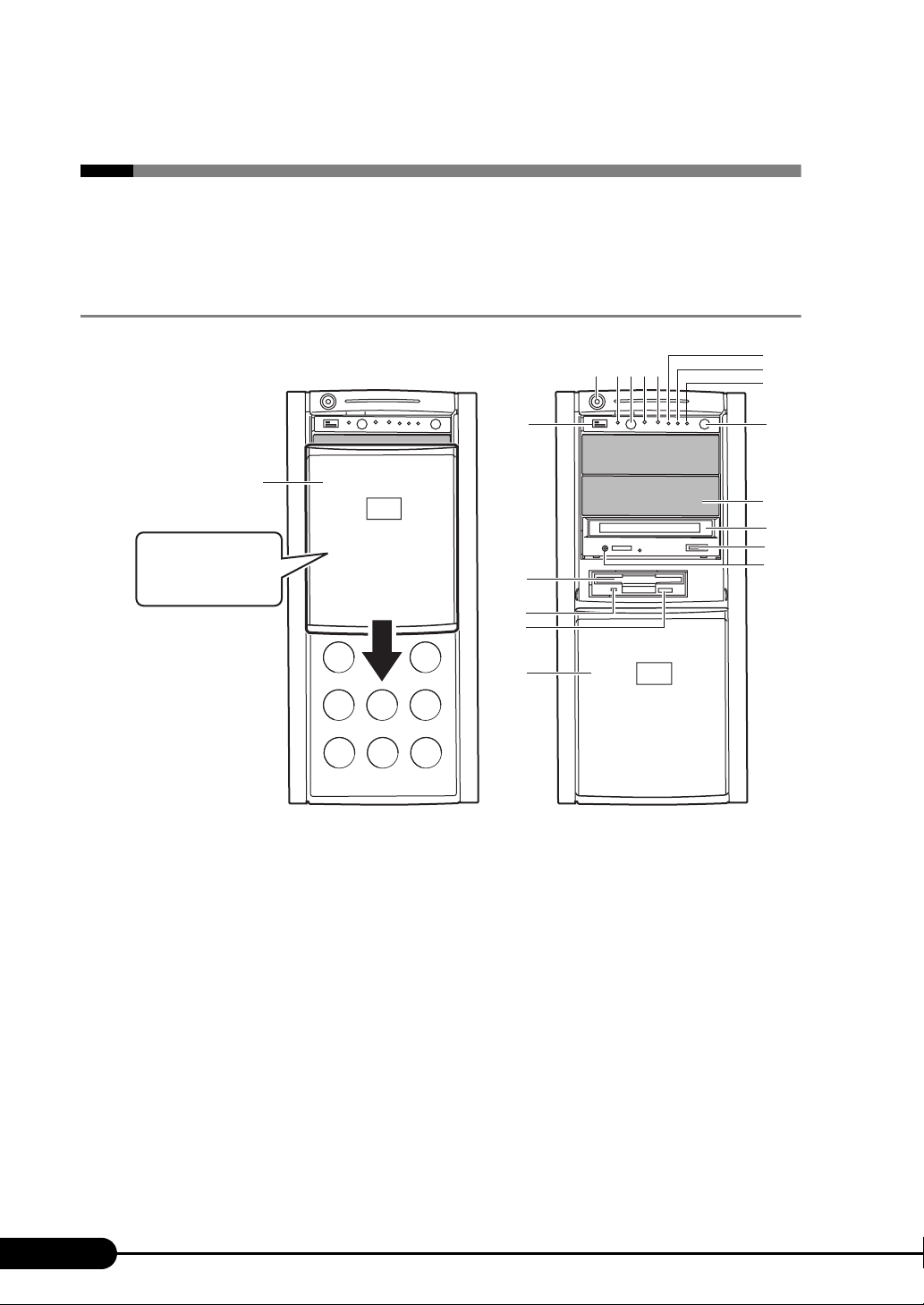
f
a
b c de
g
h
r
Drive cover
Pull the drive cover
down to the lower
end of the server.
q
p
o
n
a Drive cover key
Lock the drive cover to avoid improper handling of the server.
Remain the drive cover raised up while in server operation. For details, refer to "8.4.1 Hardware
Security" (
pg.191).
b System identification LED
This LED is used for maintenance. When pressing the system identification LED button, the
front and rear LEDs are lit blue so that the locations of devices being maintained can be
determined. Also, the [System Identification LED Display] button of ServerView can be used to
light them.
c System identification LED button
When pressing system identification LED button, the front and rear system identification LEDs
are lit blue so that the locations of devices being maintained can be determined.
i
j
k
l
m
22
Page 23
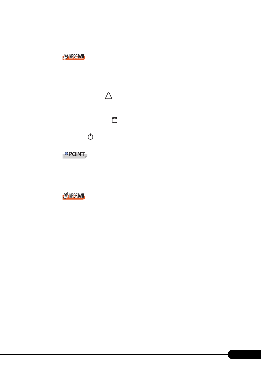
d Reset switch
Pressing this switch resets and restarts the system.
Do not restart the system when the hard disk access LED is blinking.
Data in the hard disk may be damaged.
e Maintenance switch
This switch is used only by maintenance personnel. Do not touch this.
PRIMERGY TX150 S6 User’s Guide
f System status LED ( )
This LED is lit or blink in amber when an error is detected in the server components. If this LED
is lit or blink, contact an office listed in the "Contact Information" of "Start Guide".
?
g Hard disk access LED ( )
This LED blinking when data is being written to or read from the hard disk.
h Power LED ( )
This LED is lit green when the server is turned on.
Power LED is lit in amber when the server is in standby mode (when the AC power is on and
the DC power is off), but this does not indicate an error.
i Power switch
Press this switch to turn on the server.
Do not turn off the server when the hard disk access LED is blinking.
Data in the hard disk may be damaged.
j 5-inch storage bay
Those storage bays contain a 5-inch internal device. Unlike external devices, an internal option
does not need to be connected to the outlet because its power is supplied from the server. It also
saves space.
k CD/DVD drive
This drive reads data or programs from a CD/DVD.
l CD/DVD eject button
Press this button to eject a CD/DVD.
Do not press this when the CD/DVD access LED is on.
m CD/DVD access LED
This LED blinking when data is being read from a CD/DVD.
n Drive cover
This slides up and down.
o Floppy disk eject button
Press this button to eject a floppy disk.
Do not press this when the floppy disk access LED is on.
23
Page 24
Chapter 1 Overview
p Floppy disk access LED
This LED blinking when data is being written to or read from a floppy disk.
q Floppy disk drive
This drive writes/reads data to/from a floppy disk.
r USB connector ( )
Connect peripheral equipment conforming to the USB standard (2.0 or 1.1).
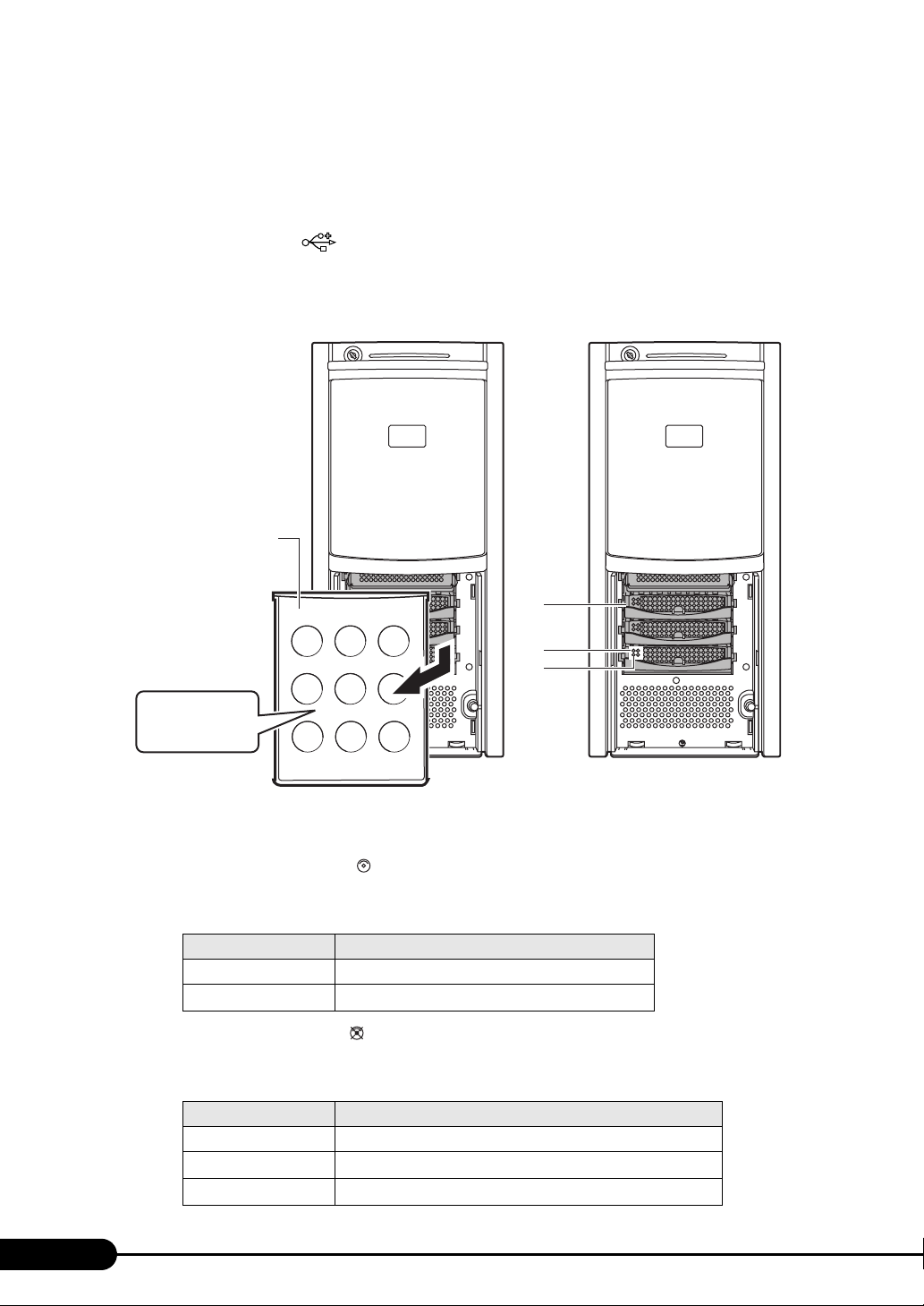
Inside the hard disk cover
Hard disk cover
a
b
c
Remove the hard
disk cover.
a 3.5-inch storage bay
Those storage bays contain an internal hard disk.
b Hard disk access LED ( )
This LED is lit green when data is being written to or read from the hard disk.
table: Meaning of the Hard Disk Access LED
LED status Hard disk access status
Off Hard disk is not accessed
Green
Hard disk is accessed
c Hard disk failure LED ( )
It is lit or blink depending on the hard disk status as follows.
table: Meaning of the Hard Disk Failure LED
LED status Hard disk status
Off In normal mode or hot spare mode
Amber (lighting)
Amber (blinking)
Error detected in the hard disk (in an array configuration)
Rebuilding
24
Page 25
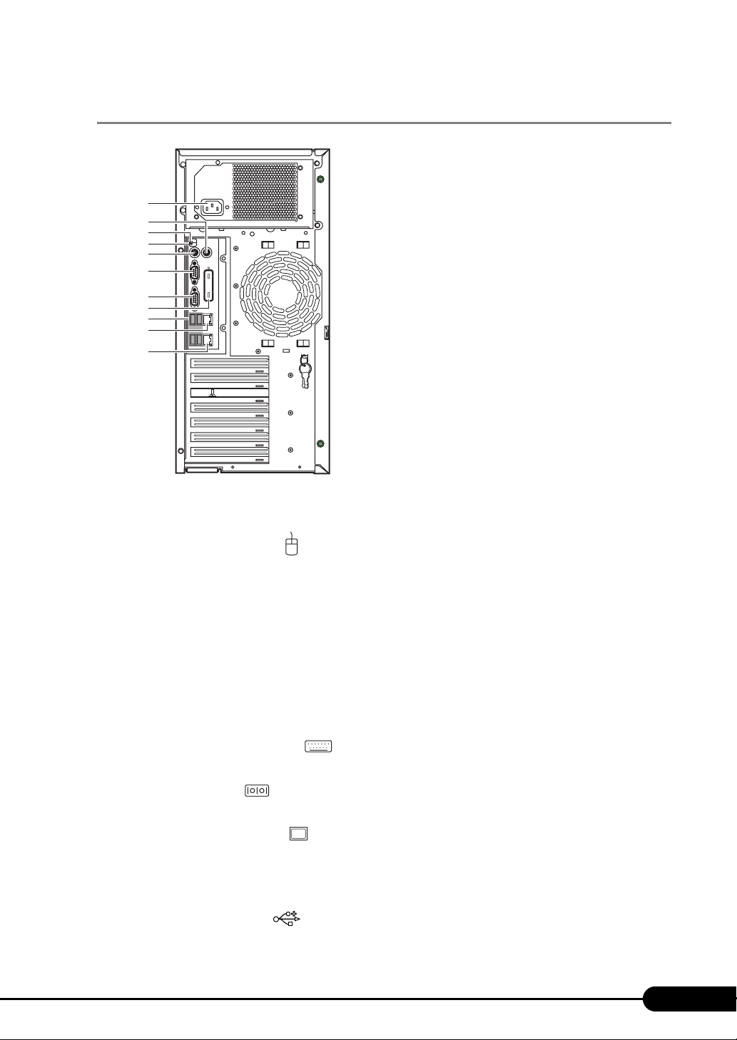
1.3.2 Server (rear view)
a
b
c
d
e
f
g
h
i
j
K
PRIMERGY TX150 S6 User’s Guide
a Power connector
Connect a power cable.
b Mouse connector ( )
Connect a mouse cable.
c System status LED
This LED is lit or blink in amber when an error is detected in the server components. If this LED
is lit or blink, contact an office listed in the "Contact Information" of "Start Guide".
d System identification LED
This LED is used for maintenance. When pressing the system identification LED button, the
front and rear LEDs are lit blue so that the locations of devices being maintained can be
determined. Also, the [System Identification LED Display] button of ServerView can be used to
light them.
e Keyboard connector ( )
Connect a keyboard connector.
f Serial port ( )
Connect cables of peripheral equipments conforming to the RS-232C standard such as a modem.
g Display connector ( )
Connect a display cable.
h Parallel port (option)
Install an optional parallel port.
i USB connector ( )
Connect peripheral equipments conforming to the USB standard (2.0 or 1.1).
25
Page 26
Chapter 1 Overview
j Service LAN Port
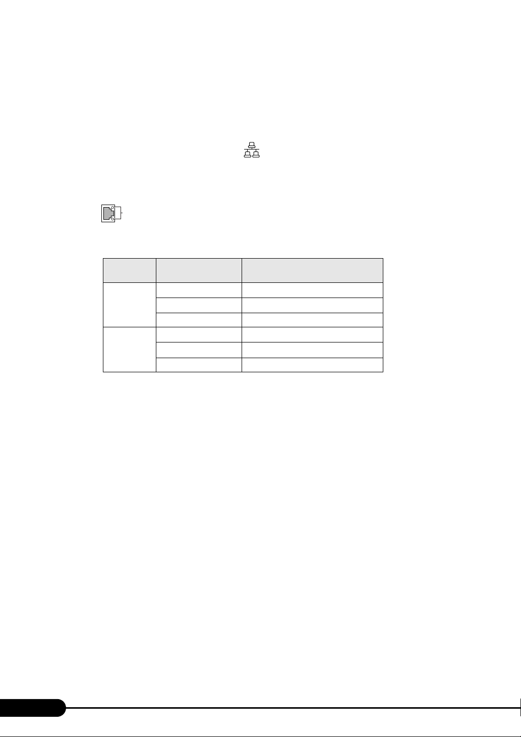
This is a LAN port for the Remote Management Controller. The Remote Management function
can be used by a Web interface as connecting a LAN cable. For information on how to use
Remote Management Controller, refer to "Appendix D Remote Management Controller"
pg.218).
(
k LAN (10/100/1000BASE-T) port ( )
Connect an Unshielded Twisted Pair (UTP).
For 1000Mbps connection, a category 5 enhanced or a category 6 cable is required.
For 10Mbps/100Mbps connection, a category 5 or higher cable is required.
The meaning of the LED is shown in the table below.
Upper LED
Lower LED
LED
LED
location
table: Meaning of the LAN port LED
LED status Connection status
Green (lighting)
Green (blinking)
Off Link is not established
Amber (lighting)
Green (lighting)
Off Connection established at 10 Mbps
Link is being established
Data is being transferred
Connection established at 1000 Mbps
Connection established at 100 Mbps
26
Page 27
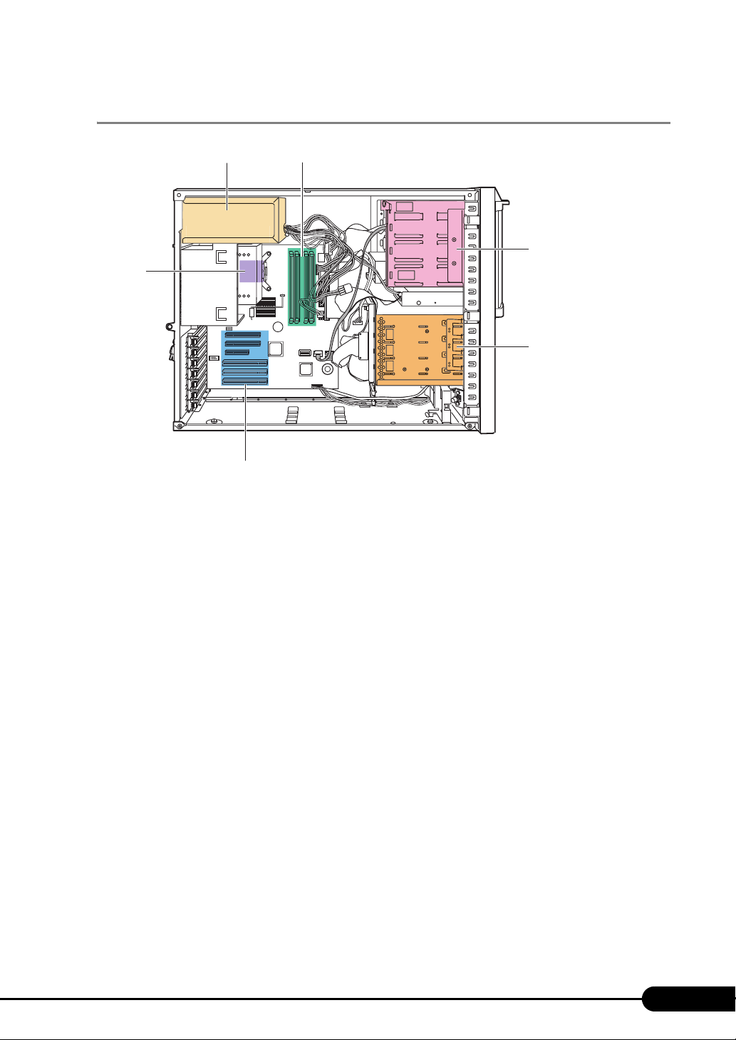
1.3.3 Server (internal)
ab
f
㪲㪩㪼㪸㫉㪴 㪲㪝㫉㫆㫅㫋㪴
e
PRIMERGY TX150 S6 User’s Guide
c
d
a Power supply unit
b Memory slot
Install memory modules.
c 5-inch storage bay
Install a 5-inch internal optional device.
d 3.5-inch storage bay
Install a 3.5-inch internal optional device.
e PCI card Slot
Install an extension card that enhances the server functions. PCI cards with a PCI bus interface
can be installed in the PCI card slots. For SAS model, a SAS controller card or a SAS array
controller card has been installed as a standard feature.
f CPU
27
Page 28
Chapter 1 Overview
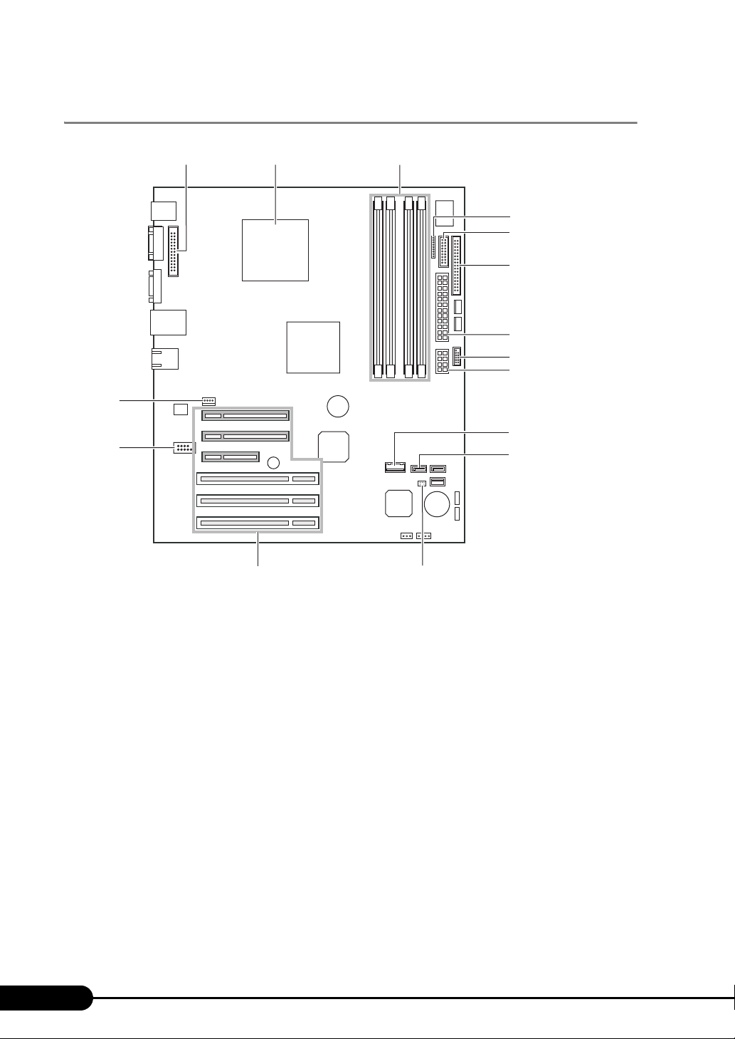
1.3.4 Baseboard
o
n
bac
d
e
f
g
h
i
j
k
lm
a Parallel port connector
Connect a parallel port cable when using a parallel port option.
b CPU socket
Install the CPU.
c Memory slot
Install a memory module. If more memory is added, the amount of the data that can be read at a
time increases and the processing performance of the server improves.
d Power fan monitoring connector
e Front panel connector
Connect a front panel cable.
f Floppy disk connector
Connect a floppy disk drive cable.
g Power connector 1
h USB connector
Connect a USB cable.
28
Page 29
PRIMERGY TX150 S6 User’s Guide
i Power connector 2
j Internal hard disk unit connector
Connect an internal hard disk unit cable for SATA model. When a SAS array controller card is
installed, this connector is not used.
k SATA connector
Connect the SATA cable of the internal DVD-ROM unit.
l Jumper
For details on jumper settings, refer to "7.1 Jumper Settings" (pg.148)
m PCI slots
Fix an expansion card. PCI slots (1 to 6) are numbered from bottom to top in the figure of
baseboard.
For SAS model, Slot 5 has been installed with a SAS array controller card as a standard feature.
n Serial connector
Connect a serial port cable when optional serial port is installed.
o System fan connector
29
Page 30
Chapter 1 Overview
1.4 Standard Operations
This section explains such standard operations as turning the server on/off and
handling the disk drive.
1.4.1 Sliding the Drive Cover
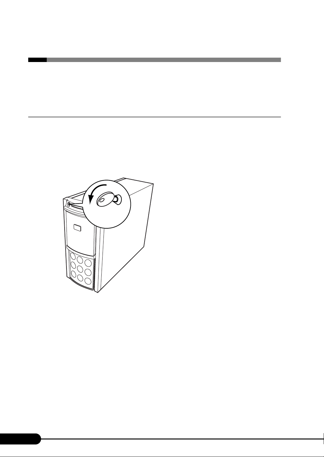
When using a floppy disk drive, a CD/DVD drive, and 5-inch internal options, slide the drive cover to
the bottom of the server.
Lock the drive cover remaining the cover raised up while in server operation. For details, refer to "8.4.1
Hardware Security" (
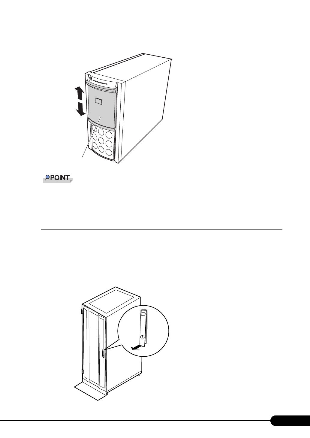
1 Turn the drive cover key counterclockwise to unlock the cover.
pg.191).
Drive cover key
30
Page 31
PRIMERGY TX150 S6 User’s Guide
2 Slide the drive cover.
Drive cover
The drive cover key is unique to each device. Do not lose the key. If the key is lost, the lock must be
broken and replaced for value. Manage the drive cover key very carefully. Contact an office listed in
the "Contact Information" of "Start Guide" if you lose it.
1.4.2 Opening the Rack Door
This section explains how to open the front and rear doors of the 40U standard rack.
For other racks, refer to rack’s manuals.
Opening the front door
1 Turn the rack key and pull the rack handle up.
31
Page 32
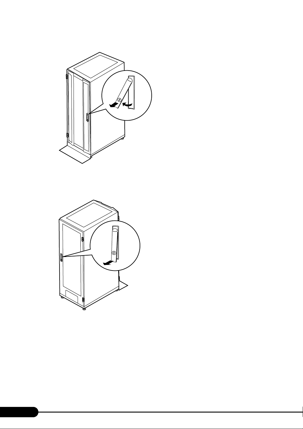
Chapter 1 Overview
2 Turn the handle in the direction of the arrow and pull it.
Opening the rear door
Turn and then pull
1 Turn the rack key and pull the rack handle up.
32
Page 33
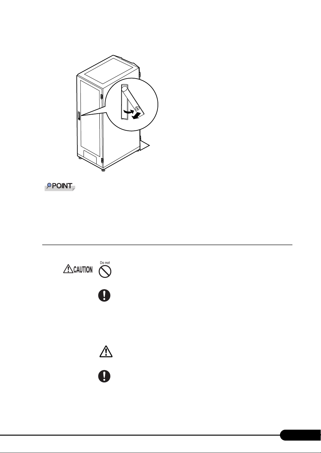
PRIMERGY TX150 S6 User’s Guide
2 Turn the handle in the direction of the arrow and pull it.
Turn and then pull
Unless you are inserting/removing media or turning the power on/off, keep the door closed. Keeping
the door closed blocks electric waves from cell phones, etc.
Do not lose the keys. If the key is lost, contact an office listed in the "Contact Information" of "Start
Guide".
1.4.3 Turning On the Server
• Do not move, strike, or shake the server when it is turned on. This can damage
the hard disk in the server and cause data loss.
• Turn the server on when the temperature is in its operating environment range
(10-35°C). For details about the operating environment, refer to "Start Guide"
and "Safety Precautions".
When operating the device outside of this operating environment, the server
may operate improperly, damage data etc.
Furthermore, Fujitsu cannot be held responsible for any related damage, malfunction,
or loss of data, etc.
• The fans rotate at high speed immediately after the server is turned on, but this
is not defective. When the temperature is in the server's operating environment
range (10-35°C), they start to rotate at normal speed later.
• Be sure to wait for 10 seconds or more after shutdown before turning the
server on.
33
Page 34
Chapter 1 Overview
1 Slide the drive cover.
"1.4.1 Sliding the Drive Cover" (pg.30)
2 Make sure that the floppy disk drive and CD/DVD drive are empty.
3 Turn on the display and peripheral devices.
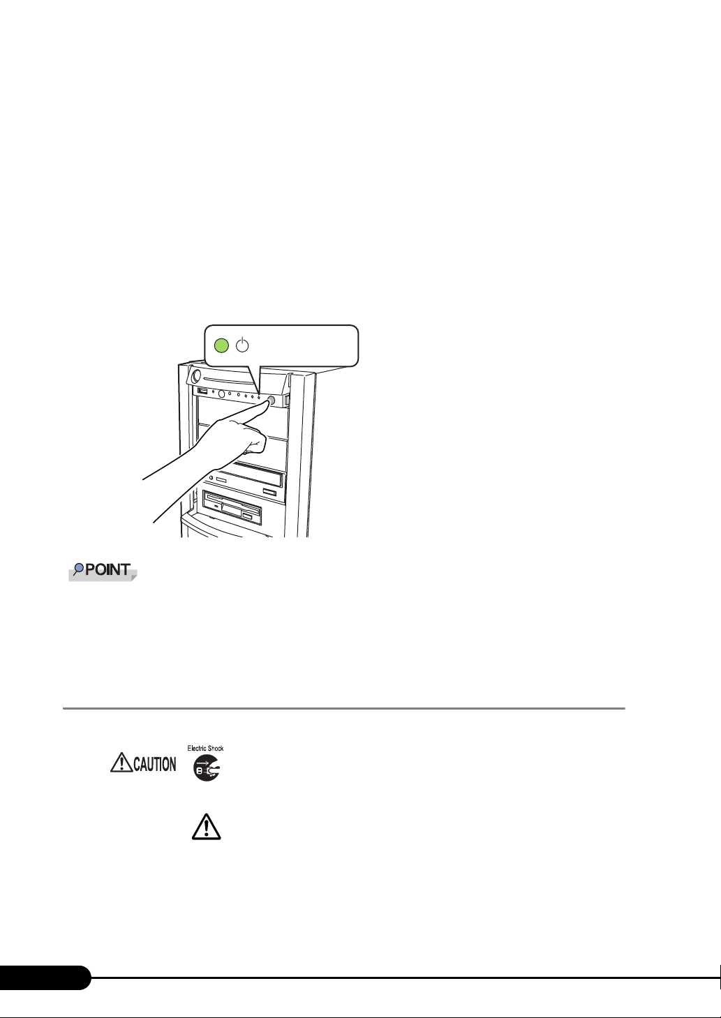
4 Press the power switch on the front of the server.
The server's power LED is lit green.
When the power is turned on, the server performs Power On Self Tests (POST). If any
abnormalities are detected by POST, error messages are displayed ("8.2.2 Error Messages"
pg.178)).
(
The server’s power
LED is lit green
The time to turn the server off can be set with the ASR setting (on the [Power On/Off] tab) using
ServerView. For details, refer to
If you press the [F12] key right after the POST memory amount check, the Boot Menu is displayed,
where you can change the boot disk ("
"3.4 Serious Error Handling (ASR)" in "ServerView User’s Guide."
1.4.4 Turning Off the Server
• In the event of smoke or sparks, immediately disconnect the electric
cord. Failure to do so may lead to a fire or electric shock.
• Follow the procedures below to turn off the server. Data can be lost if
these procedures are not followed correctly.
1 Slide the drive cover.
"1.4.1 Sliding the Drive Cover" (pg.30)
2 Make sure that the floppy disk drive and CD/DVD drives are empty.
34
How to start BIOS Setup Utility" (pg.149)).
Page 35
PRIMERGY TX150 S6 User’s Guide
3 Shut down the OS.
In the following cases, the server is turned off after the OS is shut down (Step 4 is not necessary).
• Windows OS
• ServerView is installed
In other cases, make sure that the access LEDs of floppy disk and hard disk are off when the OS
is shut down.
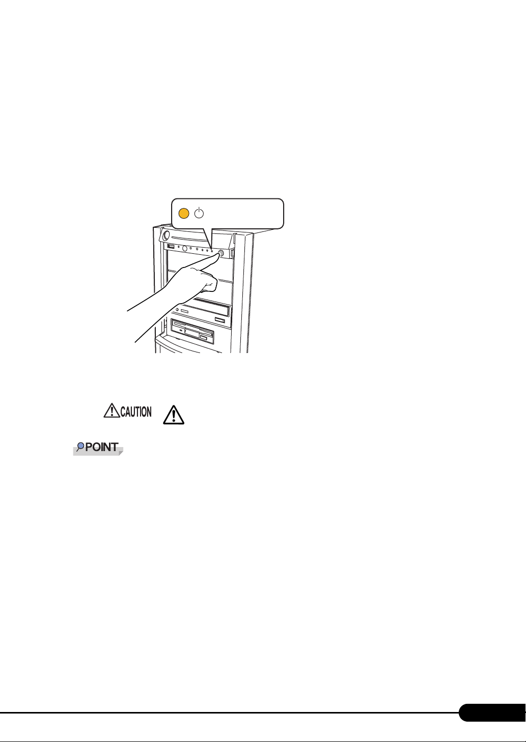
4 Press the power switch on the front of the server.
The server's power LED is lit amber.
The servers power
LED is lit amber
5 Turn off the display and peripheral devices.
• Be sure to wait for 10 seconds at least after shutdown before turning the
server on.
The time to turn the server off can be set with the ASR setting (on the [Power On/Off] tab) using
ServerView. For details, refer to
"3.4 Serious Error Handling (ASR)" in "ServerView User’s Guide."
Cautions when turning the power off (Windows Server 2003)
For the power switch operation mode of this server, you can specify the following modes depending on
the OS settings (normally, "Shutdown" is specified).
"Do Nothing", "Prompt Input", "Standby", "Hibernation", or "Shutdown"
On this server, functions corresponding to "Standby" and "Hibernation" are supported as BIOS and
hardware functions. However, some drivers and software installed in the server do not support these
functions. For this reason, functions corresponding to "Standby" and "Hibernation" are unavailable on
this server. When the operating mode is set to "Standby" or "Hibernation", the system may operate
improperly or hard disk data may be corrupted.
For details about operating mode settings, refer to the manual supplied with the OS.
35
Page 36
Chapter 1 Overview
1.4.5 Inserting and Ejecting a Floppy Disk
Cautions
When using floppy disks, note the following points to avoid failures:
• Do not expose the disk to any fluids.
• Do not open the shutter of the floppy disk and touch the disk surface.
• Do not bend the floppy disk or place heavy objects on it.
• Do not expose the floppy disk to strong magnetic fields.
• Do not drop the floppy disk on hard surfaces.
• Do not store the disk in extremely hot or cold conditions.
• Do not store the disk in humid or dusty conditions.
• Do not put layers of labels on the floppy disk. Doing so may cause the drive to be clogged with the
disk.
• Keep the disk away from moisture condensation or water droplets.
Inserting the floppy disk
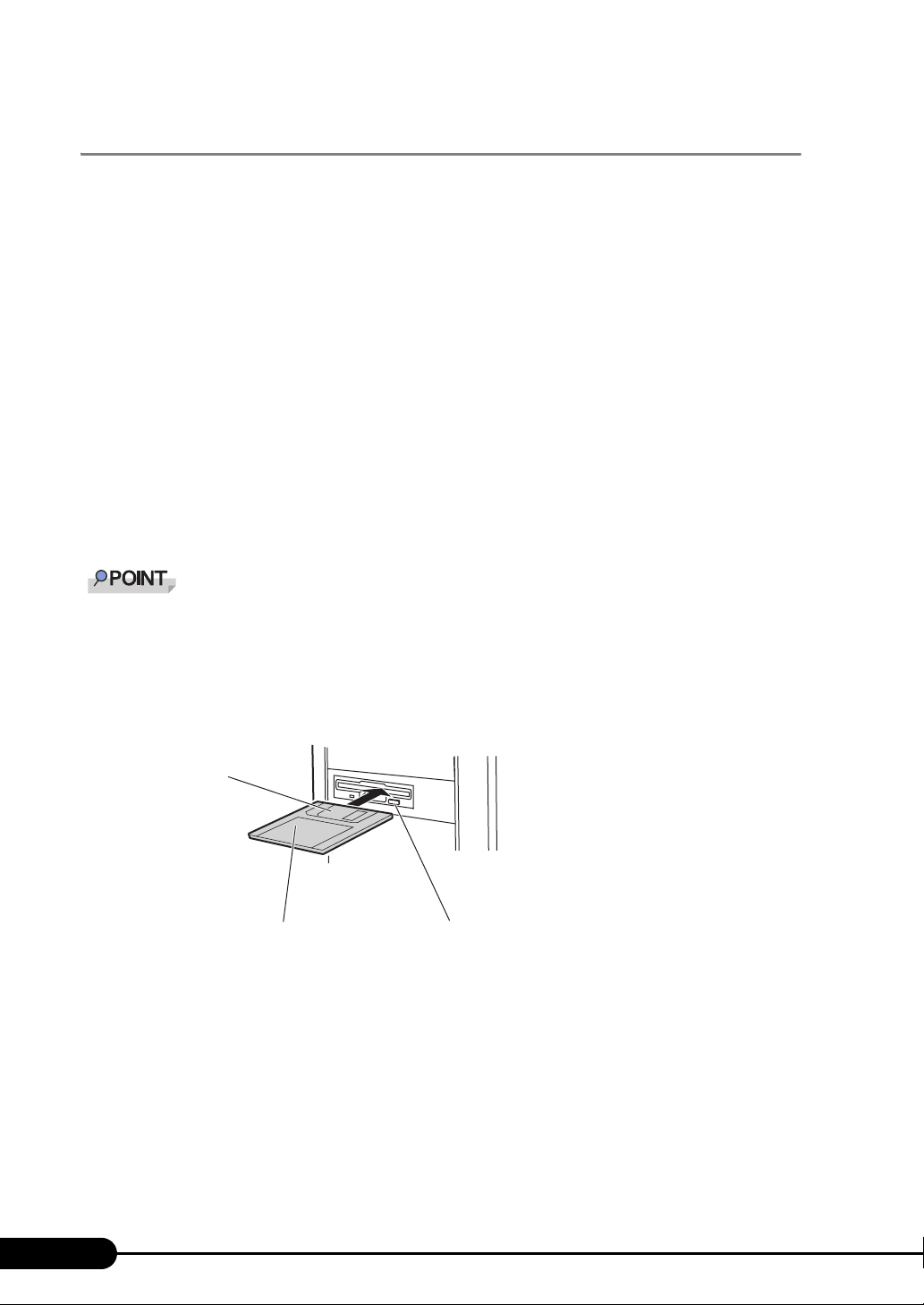
Use a floppy disk formatted in DOS/V. Operations are not guaranteed when you use other floppy
disks.
1 Insert the floppy facing the label up into the floppy disk drive at the side with a
shutter.
It makes a clicking sound and the floppy disk eject button pops out.
Shutter
Label
Floppy disk eject button
36
Page 37
Ejecting the floppy disk
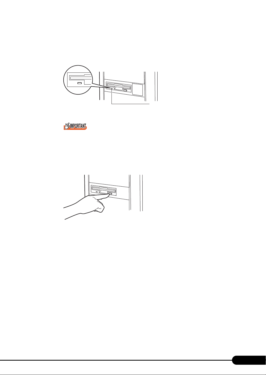
1 Make sure that the floppy disk access LED is off.
Do not eject the floppy disk while the floppy disk access LED is on. Doing so may damage
data.
2 Press the floppy disk eject button.
The floppy disk comes out.
PRIMERGY TX150 S6 User’s Guide
Floppy disk access LED
37
Page 38

Chapter 1 Overview
1.4.6 Inserting and Ejecting a CD/DVD
This section explains how to insert and eject a CD/DVD.
To prevent causes of mechanical failures, observe the precautions about handling CD/DVD stated
below.
Cautions for handling drives
• Avoid an area with high humidity and airborne dust level. Electric shocks and/or server failures may
be caused by liquids such as water, or metallic items, such as paper clips, entering a drive.
• Do not use the drive in an area where is easily influenced by shocks and vibrations.
• Do not insert any objects other than the specific CD/DVDs.
• Do not pull on, press hard, or handle the CD/DVD tray roughly.
• Do not disassemble the CD/DVD drive.
• Before use, clean the CD/DVD tray using a soft, dry cloth.
• As a precaution, remove discs from the CD/DVD drive when the drive is not to be used for a long
time. Keep the CD/DVD tray closed to prevent foreign matter, such as dust, from entering the CD/
DVD drive.
Cautions for handling media
• Hold CD/DVDs by their edges to avoid contact with the disc surface.
• Do not contaminate the CD/DVD surface with fingerprints, oil, dust, etc. If dirty, clean with a soft,
dry cloth, wiping from the center to the edge. Do not use benzene, thinners, water, record sprays,
antistatic agents, or silicone-impregnated cloth.
• Be careful not to damage the CD/DVD surface.
• Keep the CD/DVDs away from heat sources.
• Do not bend or place heavy objects on CD/DVDs.
• Do not attach stickers or similar to the label side. Doing so may cause rotational eccentricity and
abnormal vibrations.
• When a CD/DVD is moved from a cold place to a warm place, moisture condensation on the CD/
DVD surface can cause data read errors. In this case, wipe the CD/DVD with a soft dry cloth then let
it air dry. Do not dry the CD/DVD using devices such as a hair dryer.
• To avoid dust, damage, and deformation, keep the CD/DVD in its case whenever it is not in use.
• Do not store CD/DVDs at high temperatures. Areas exposed to prolonged direct sunlight or near
heating appliances are to be avoided.
38
Page 39
Inserting the CD/DVD
n
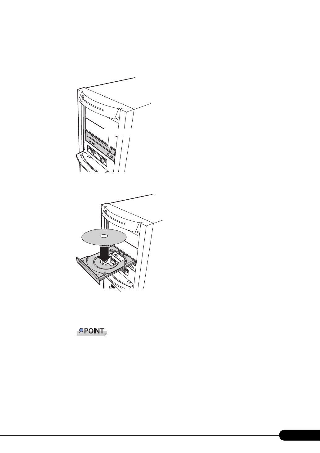
1 Make sure the server is turned on and press the CD/DVD eject button.
The CD/DVD tray comes out a little.
CD/DVD eject butto
2 Place the CD/DVD (label side up) onto the tray.
PRIMERGY TX150 S6 User’s Guide
CD/DVD tray
3 Press the CD/DVD eject button again.
The tray is inserted into the server and CD/DVD is set.
When CD/DVD is set, the CD/DVD access LED is lit. To go to next operation, confirm that the
LED is off.
Ejecting the CD/DVD
To eject the CD/DVD, confirm that the CD/DVD access LED is off and then press the CD/DVD eject
button.
39
Page 40
Chapter 1 Overview
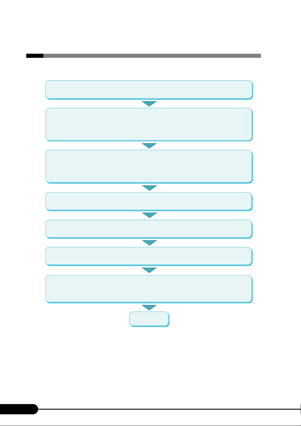
1.5 Workflow
To start the server operation, perform the following procedures.
Installing the server
Refer to "Safety Precautions" and "Start Guide" to install the server on a suitable location.
Preparing the server
- Install internal options
- Set configurations of hardware
Refer to "2.1 Preparation on the Server", "Chapter 6 Installing Internal Options" and
"Chapter 7 Configuring Hardware and Utilities".
Selecting a installation method and observing precautions on installation
Refer to "2.2 Selecting an Installation Method" to decide what installation method to use.
Prior to OS installation, observe precautions with referring to "2.3 Precautions on Installation".
OS installation
Refer to "Chapter 3 OS Installation" to perform OS installation.
Installing internal options
Refer to "Chapter 6 Installing Internal Options" to install the internal options.
Operations before running the server
Before operating the server, refer to "Chapter 4 Operations after OS Installation".
High reliability tools installation
For ServerView, the settings is required prior to the server operation.
For details on each high reliability tool, refer to "Chapter 5 High Reliability Tools".
Start operations
40
Page 41
Chapter 2
Checking before OS
Installation
This chapter explains the preparation and
cautions for the server before OS installation.
Observe this chapter before starting installation.
2.1 Preparation on the Server
2.2 Selecting an Installation Method
2.3 Precautions on Installation
. . . . . . . . . . . . . . . . . . . . . . . . 42
. . . . . . . . . . . . . . . . . . . . . . . . 46
. . . . . . . . . . . . . . . . . . . 45
41
Page 42
Chapter 2 Checking before OS Installation
2.1 Preparation on the Server
Before starting installation of the OS, install internal options in the server and perform
hardware settings.
2.1.1 Installing Internal Options
The installation sequence depends on the internal options which must be installed before or after
installation of the OS. For installation procedures, refer to "Chapter 6 Installing Internal Options"
pg.111).
(
z Options to be installed before the OS installation
• Internal hard disk unit to install OS
• Memory modules
• Expansion cards
• USB floppy disk drive
ServerStart floppy disk or driver disk is used to install the OS. Connect the USB floppy disk drive in
advance.
z Options to be installed after the OS installation
• Optional SCSI/SAS devices
• Internal hard disk units where the OS is not installed
If an internal option device that must be installed after the OS installation has been already installed,
remove the device, and reinstall the device after completion of OS installation.
Installing optional external devices
When installing an external option SCSI/SAS device and/or a USB connected device, turn off power
supply or unplug their connection cables from the server during the OS installation. Connect them again
after the OS installation.
Cautions for installing an expansion card
When using an expansion card, read the notes on the expansion card.
42
Page 43
PRIMERGY TX150 S6 User’s Guide
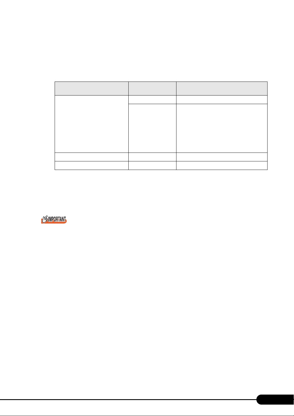
Cautions for installing a memory module
The supported maximum capacity varies depending on OS to be installed. Furthermore, since the server
uses part of memory as PCI resources, the maximum available size has limitation. The table below
describes maximum installable memory size and available memory size.
table: Onboard-capable memory size and available size
OS
Windows Server 2003
SBS 2003
Windows Server 2003 x64 Installed memory size
Linux Installed memory size Same as the installed memory capacity
*1: The installed memory size may be changed to available memory size by setting /PAE option in the
Boot.ini file. For details on editing the Boot.ini file, refer to the manual for OS to be installed.
Installed memory
size
Up to 2GB Same as the installed memory capacity
2GB to 4GB As shown below, available memory size varies
depending on the settings of [NX Memory
Protection] of [Advanced Processor
Configuration] submenu on [Advanced] menu
for BIOS Setup Utility.
• [Disabled]: 2GB
• [Enabled]: Equivalent to the installed
Same as the installed memory capacity
Available memory size
memory size
*1
LAN cable
Connect a LAN cable to the server that is not able to access the Internet.
Security problems may occur if you access the Internet during setup operation. Do not access the
Internet until the setup completes.
When the OS installation and/or automatic installation of an application are performed without
connecting the LAN cable to the LAN card, an error may be recorded in the event viewer after setup
completes.
Connect a LAN cable to LAN card after Service Pack 2 is applied when:
• Perform a half-duplex connection with 10 Mbps
®
• Install Intel
When performing OS installation with ServerStart to the server with a LAN card installed, Intel
PROSet is automatically installed.
PROSet
®
43
Page 44

Chapter 2 Checking before OS Installation
2.1.2 Hardware Settings
Before starting installation of the OS, set necessary hardware, such as BIOS Setup Utility.
BIOS Setup Utility
The BIOS Setup Utility must be set in the following cases. For details on how to set BIOS Setup Utility,
refer to "7.2 BIOS Setup Utility" (pg.149).
z Changing drives to boot
To change drives to boot, start up BIOS Setup Utility, select the [BOOT] menu then change the boot
drive. For how to setup boot drive, refer to "7.2.17 Boot Menu" (
pg.168)
44
Page 45

PRIMERGY TX150 S6 User’s Guide
2.2 Selecting an Installation Method
When installing the OS with ServerStart, there are multiple installation methods. Prior
to OS installation, refer to the following to decide on the method.
2.2.1 Supported OS
The following operating systems can be installed with using ServerStart V6.711.
• Microsoft
• Microsoft
• Microsoft
• Microsoft
• Microsoft
• Microsoft
• Microsoft
• Microsoft
®
Windows Server® 2003, Standard Edition
®
Windows Server® 2003, Enterprise Edition
®
Windows Server® 2003, Standard x64 Edition
®
Windows Server® 2003, Enterprise x64 Edition
®
Windows Server® 2003 R2, Standard Edition
®
Windows Server® 2003 R2, Enterprise Edition
®
Windows Server® 2003 R2, Standard x64 Edition
®
Windows Server® 2003 R2, Enterprise x64 Edition
ServerStart does not support OS installation of SBS 2003 / Linux.
Any of unsupported OS can not be installed.
2.2.2 Installation Modes of ServerStart
Quick installation mode
This mode completes the OS installation by executing plain settings. Select this mode when you want to
install the OS quickly and simply. To install while maintaining the established RAID environment,
the quick installation mode must be selected to install the OS.
Select [Logical Disk 0] in the [Select the Boot Controller and Boot Disk] window and install the OS.
Expert mode
In this mode, start up Disk Manager and format the partition where your OS is installed prior to
installation of the OS. Select the expert mode only when installing the OS while maintaining the existing
partitions. Also, when using ServerStart while maintaining the existing partitions, start up Disk
Manager, format an installation partition and install the OS.
45
Page 46

Chapter 2 Checking before OS Installation
2.3 Precautions on Installation
Observe all the following notes before starting OS installation.
2.3.1 Installation Partition Size
The installation partition sizes are stated as below when using ServerStart to install your OS.
• Maximum size: 2TB
• Minimum size: 2200MB
z Notes
• When setting the OS and BOOT partitions on different partitions, specify the partition size directly.
(The BOOT partition indicates the partition for startup. Minimum information required for startup
such as "ntldr" is allocated on the partition. The OS partition indicates the partition for installing the
OS.)
• In either of the following cases, specify a partition size 2TB or less.
• When the same partition is specified as the OS and BOOT partitions
• When different partitions are specified as the OS and BOOT partitions
• The OS cannot be installed on a partition larger than 2TB.
2.3.2 Notes on Configuring RAID
Observe the notes described as follows prior to configuring RAID.
Hard disk unit
• Only internal hard disk units can be used.
Although up to four internal hard disk units can be installed on this server, the number of available
hard disk units to be installed varies RAID level to be configured. For details, refer to Array
Controller Document & Tool CD.
• Be sure to use hard disk units of the same model with the same capacity.
Array configuration
Array controllers to be used vary depending on model of the server. For RAID configuration of each
model, refer to applicable manuals.
z When using a SAS controller card (Integrated Mirroring SAS) (SAS Model
Only)
Configure RAID with an internal hard disk which is connected to a SAS controller card. The array
controller to be employed is "Integrated Mirroring SAS" and available RAID level is "RAID 1" only.
For details, refer to "Integrated Mirroring SAS Users Guide" in Array Controller Document & Tool CD.
46
Page 47
PRIMERGY TX150 S6 User’s Guide
z When using a SAS array controller card (MegaRAID SAS)
Configure RAID with an internal hard disk unit which is connected to a SAS array controller card. The
array controller to be employed is "MegaRAID SAS" and available RAID level is "RAID 0 / RAID 1/
RAID 1+0 / RAID 5/ RAID 6". For details, refer to "MegaRAID SAS Users Guide" in Array Controller
Document & Tool CD.
z When using an onboard software RAID (SATA Model Only)
Configure RAID with an internal hard disk unit which is connected to an internal hard disk connector on
the baseboard. The array controller to be employed is "Embedded MegaRAID SATA" and available
RAID level is "RAID 0" or "RAID 1". For details, refer to "Embedded MegaRAID SATA Users Guide"
in Array Controller Document & Tool CD.
Only one array controller is available with connecting to the internal hard disk. Multiple array
controllers can not be used. When a SAS array controller card (PG-248B / PG-248C) is installed in
SATA model, available array controller is "MegaRAID SAS" only.
Notes
• When RAID-configured hard disk unit is used
Hard disk units that have been used before may have unwanted partition information or array
configuration information, which may cause unexpected problems. If you connect any hard disk units
with usage history to this server, format them at low level on another system before connecting them
to the server. For information on how to format the hard disk, refer to the manual supplied with the
system to be used.
• Number of hard disk units
If the number of actually installed units is less than that the setting for the number of units (plus one,
when hot spare is specified), installation using ServerStart is aborted because of an error.
When the number of actually installed hard disk units is larger than configured, the disk units are set
up according to the setting. Extra units will be configured as standby disk units.
2.3.3 Cautions for Using ServerStart
Observe the cautions described below when the OS installation is performed with ServerStart.
Operating ServerStart
Mainly, a mouse is used for ServerStart operations. In some cases, operation with the [Tab] key or
cursor are not available. Be sure to use a mouse while operating ServerStart.
47
Page 48
Chapter 2 Checking before OS Installation
Configuration file (SerStartBatch.ini)
A configuration file stores the server setup and client information configured in ServerStart. To create a
configuration file, use the ServerStart floppy disk supplied with this server. Store only one file on each
floppy disk. Do not set the ServerStart floppy disk to the write-protected state. You can use any name for
the configuration file. However, the file must be installed in the server as "SerStartBatch.ini". When
installing the configuration file, make sure to save it as "SerStartBatch.ini" on the ServerStart floppy
disk. Start up ServerStart, insert the ServerStart floppy disk containing "SerStartBatch.ini", and click
[Start] to install the server.
Ejecting PRIMERGY Startup Disc
Do not eject PRIMERGY Startup Disc while ServerStart is running. If the PRIMERGY Startup Disc is
ejected and inserted again, ServerStart starts up in multiple windows, and settings you have made may
be lost.
Exiting ServerStart
After operation in the expert mode, exiting ServerStart restarts the system. Remove discs from the
floppy disk and CD/DVD drives and click [OK]. When the display on the screen disappears, turn off the
system.
License for use of system for ServerStart
"License for Use of System for ServerStart" linked from the ServerStart startup window is a license for
use of Windows PE contained in ServerStart of the PRIMERGY Startup Disc. Windows PE for starting
up ServerStart can be only used for installing Windows Server 2003 R2 and Windows Server 2003,
provided under a separate legal license.
Display of onboard LAN
Display of an onboard LAN on the OS is as below when OS installation performs with ServerStart.
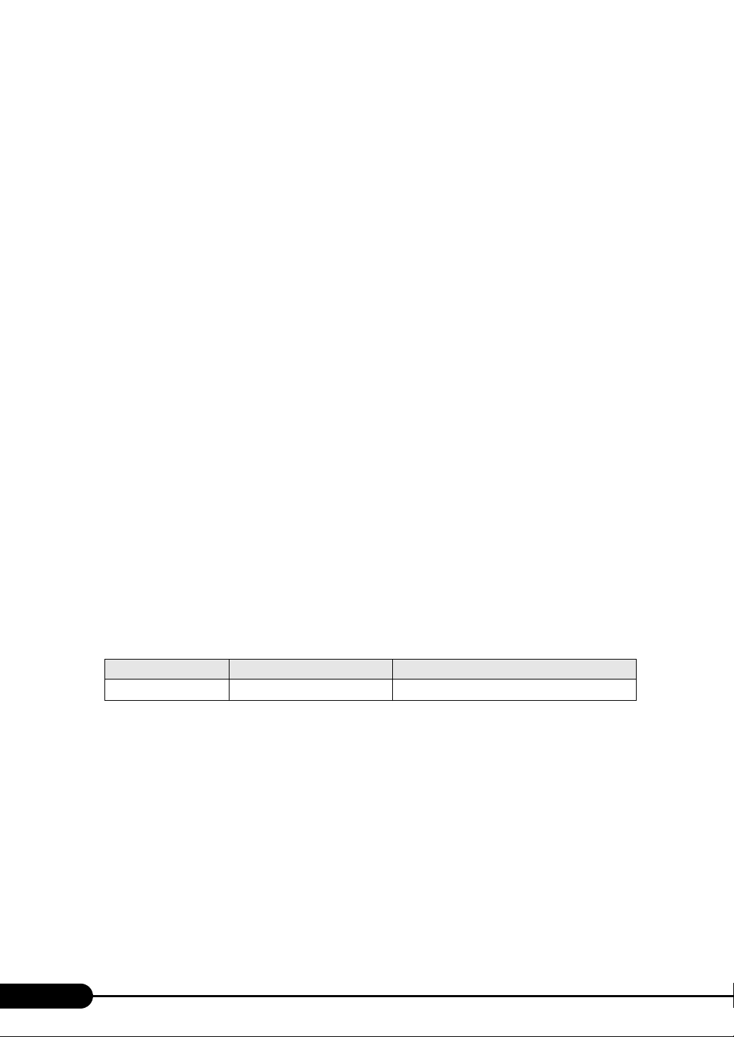
table: Display of onboard LAN
LAN port Property on My Network LAN device name
Onboard LAN Local Area Connection
BroadcomNetXtreme Gigabit Ethernet
Adapter numbers
For ServerStart, onboard multiple LAN adapters (network adapter) may be configured on OS
installation wizard.
To configure multiple LAN cards, select the adapter numbers in order of Adapter 1 and Adapter 2, and
enter settings for each adapter. Note that the order of adapter numbers is not necessarily the same as the
order of slots for the installed LAN adapters. This means that the setting for Adapter 1 is not always
applied to the onboard LAN. After installing the OS, check the LAN adapters to make sure that they are
configured as intended.
Setting up the printer
ServerStart does not support setup of printers. Perform installation after setup is completed.
48
Page 49
PRIMERGY TX150 S6 User’s Guide
2.3.4 Automatic Driver Installation with ServerStart
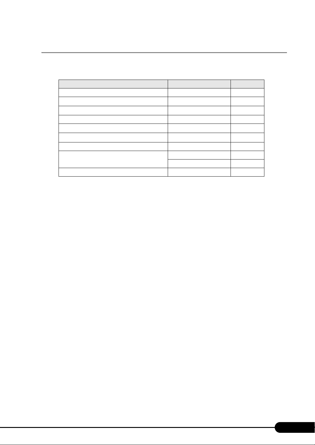
ServerStart supports automatic driver installation for the following expansion cards.
table: Automatic driver installation
Onboard controller/Card type Product ID Bus
Onboard FDD/IDE/SATA - -
Onboard SATA - -
Onboard LAN -
Onboard VGA - PCI
Onboard Software RAID
SAS controller card - PCI-E
SAS array controller card PG-248B/ PG-248C PCI-E
LAN Card PG-1853 PCI
SCSI card PG-2281 PCI-E
--
PG-289 / PG-2861 PCI-E
PCI-E
49
Page 50
Chapter 2 Checking before OS Installation
50
Page 51
Chapter 3
OS Installation
This chapter explains how to install the OS in the
server using ServerStart.
3.1 Quick Installation Mode
3.2 Expert Mode
. . . . . . . . . . . . . . . . . . . . . . . . . . . . . . . . . . 58
. . . . . . . . . . . . . . . . . . . . . . . . . . 52
51
Page 52
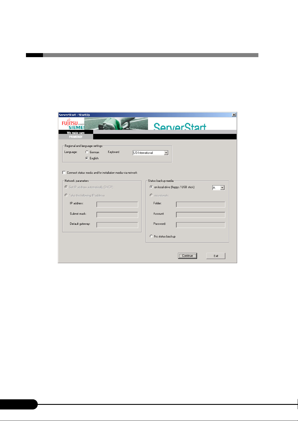
Chapter 3 OS Installation
3.1 Quick Installation Mode
In this quick installation mode, the OS is installed after configuring minimum required
settings. To install the OS quickly and easily, use the quick installation mode.
1 Turn on the server and insert PRIMERGY Startup Disc immediately.
ServerStart starts up. The select-media window for the configuration file appears.
52
Page 53
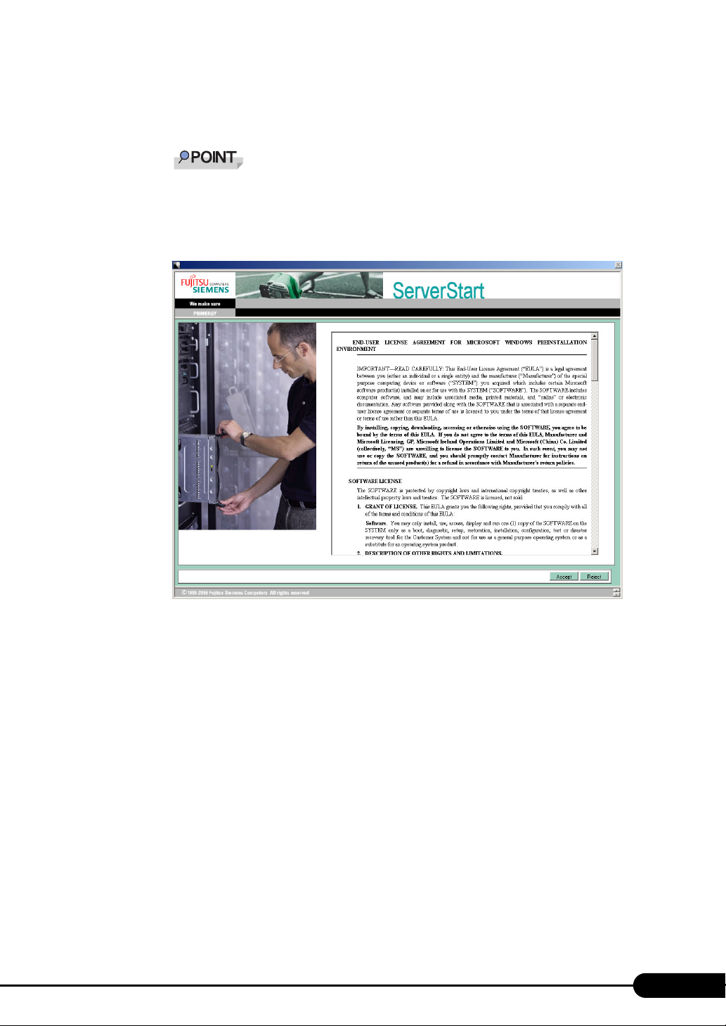
PRIMERGY TX150 S6 User’s Guide
2 Insert the ServerStart floppy disk supplied with the server. Make sure that "on
local drive (floppy/USB stick)" and "A:" are selected and click [Continue].
Set the ServerStart floppy disk in the write-enabled state.
The [Initialization of ServerStart core running] window appears and the ServerStart initialization
process starts. Depending on hardware configuration, this process may take a few minutes. After
completion, the license agreement window appears.
53
Page 54
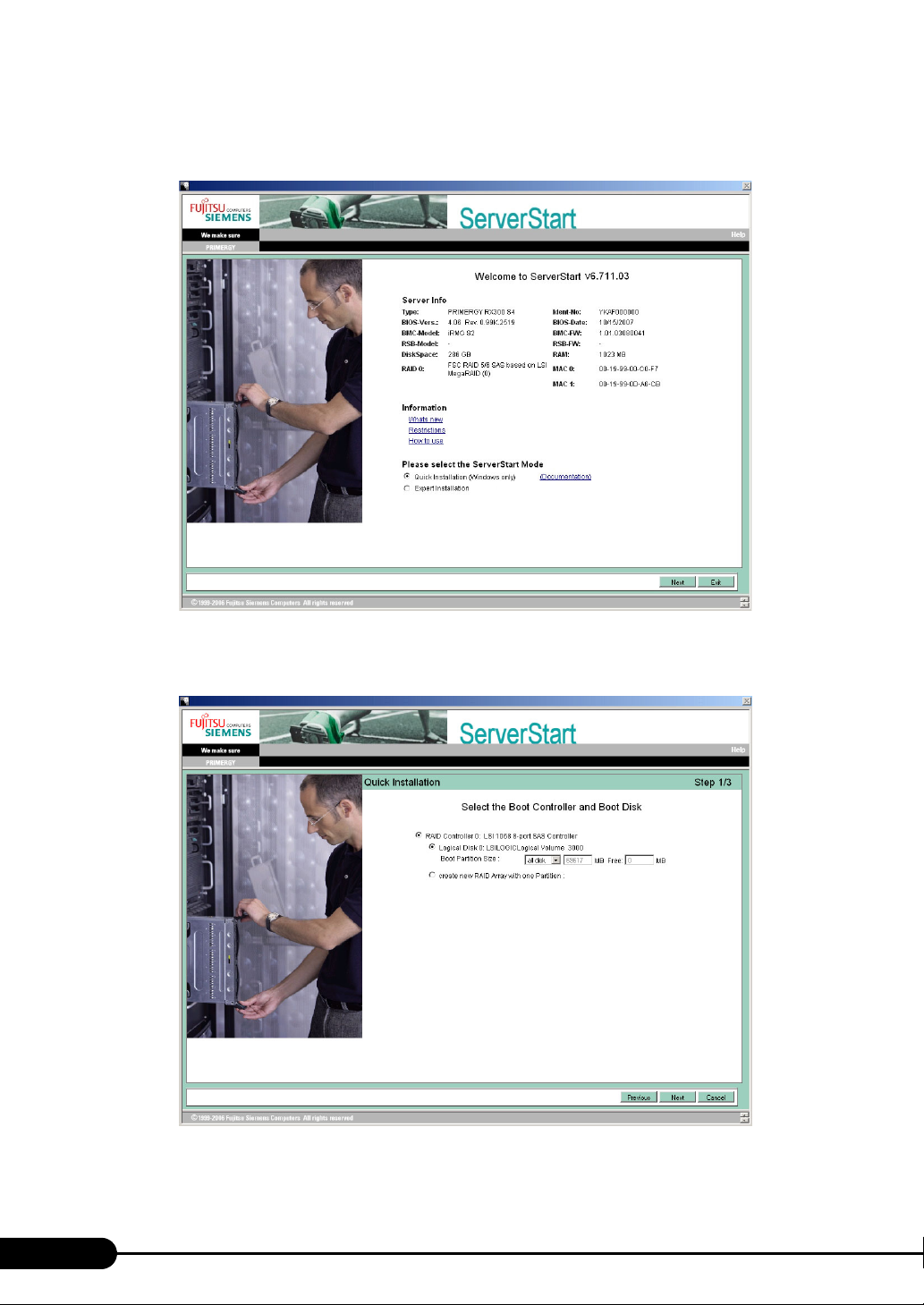
Chapter 3 OS Installation
3 Click [Accept].
The [Welcome to ServerStart] window appears.
4 Select "Quick Installation (Windows only)" and click [Next].
The [Select the Boot Controller and Boot Disk] window appears.
54
Page 55
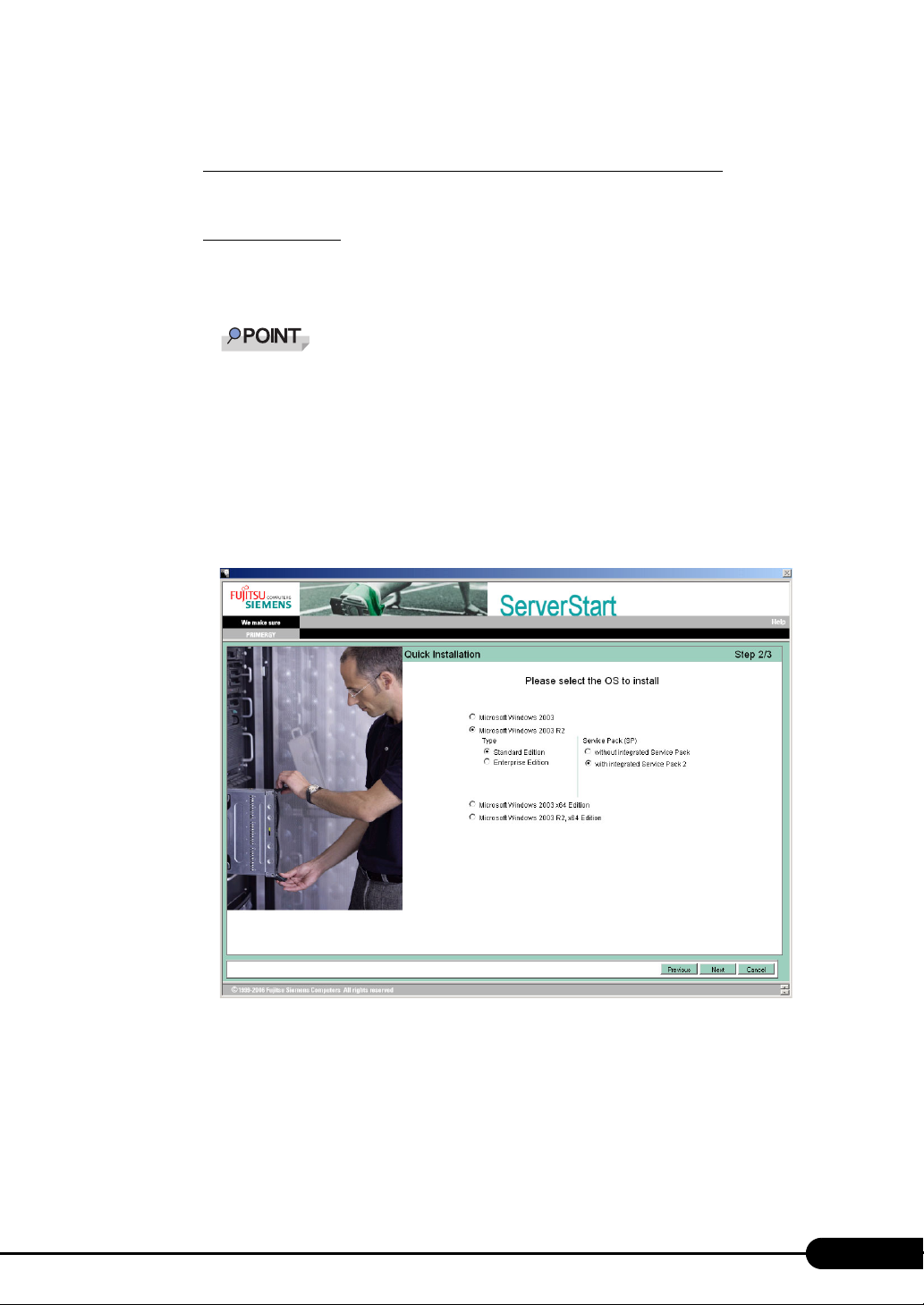
PRIMERGY TX150 S6 User’s Guide
5 Set configuration of the RAID and disks and click [Next].
To install the OS while maintaining the established RAID environment
Select [Logical Disk 0] and specify partition size to be created.
One partition can be created. Select [Logical Disk 0] since the RAID is not required to be created.
To configure RAID
Select [create new RAID array with one partition] and specify the RAID level to be configured
and the size of the partition.
All existing RAID will be deleted. Also, only one partition can be created.
When [Auto] is selected, the RAID is configured with the following levels, depending on the
number of the installed disk units.
• When two hard disk units are installed: RAID 1
• When three hard disk units are installed: RAID 5
• When more than three hard disk units are installed: RAID 5 with hot spare function
The configurations of the created partitions are as follows.
• Volume label: system
• File system: NTFS
• Partition configuration: Boot/OS
The [Please select the OS to install] window appears.
6 Select the OS to be installed and click [Next].
55
Page 56
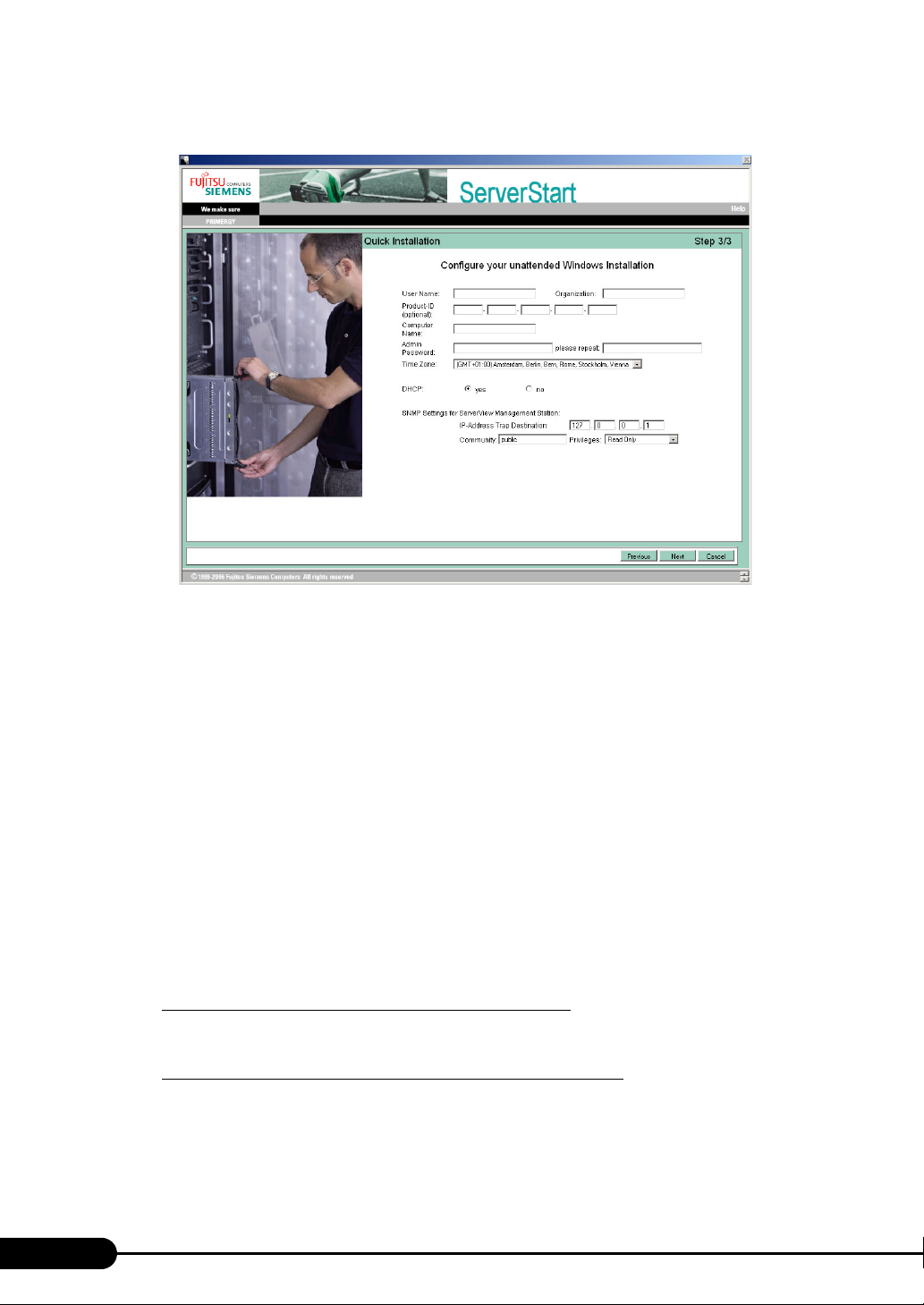
Chapter 3 OS Installation
The [Configure your unattended Windows Installation] window appears.
7 Set the items and click [Next].
The [Summary] window appears.
8 Confirm the settings and click [Start Installation].
9 Click [Start now].
Installation starts.
1. If a message prompts you to insert Array Controller Document & Tool CD, insert
the CD/DVD and click [OK].
2. If a message prompts you to insert Service Pack CD-ROM, Insert the CD-ROM and
click [OK].
3. For Windows Server 2003 x64, a message appears and prompts you to insert
Startup Disc Win64 and restart the system. Insert Startup Disc Win64.
10 When a message prompts you to insert the OS CD/DVD, insert the CD/DVD
and click [OK].
For Windows Server 2003 / Windows Server 2003 x64
1. Insert the OS CD/DVD (Installation disc).
After files are copied, a message prompts you to eject the CD/DVD and floppy disk.
For Windows Server 2003 R2 / Windows Server 2003 R2 x64
1. Insert the OS CD/DVD (Installation disc) Disc 1.
After files are copied, a message prompts you to insert the Disc 2.
2. Insert the OS CD/DVD (Installation disc) Disc 2.
After files are copied, a message prompts you to eject the CD/DVD and floppy disk.
56
Page 57

PRIMERGY TX150 S6 User’s Guide
11 Eject the CD/DVD and floppy disk and click [OK].
The system is restarted.
The system continues the installation operation after restart.
Setup of OS GUI and installation of LAN utility, Service Pack, and Active Directory are
performed automatically.
12 When a confirmation message to restart appears, click [Restart].
The system restarts and installs high reliability tools.
Thus the Command Prompt windows may appear and disappear during installation of Server-
View, the installation process is properly proceeding.
13 Press any key when a message notifies completion of installation.
14 Restart the system.
Click [Start] – [Shutdown]. Select [Restart] and click [OK].
The system restarts.
15 Perform the settings for the RAID management tool (ServerView RAID).
For the setting procedures, refer to the manuals in Array Controller Document & Tool CD.
• Settings of an array administrator account
The Windows user account is required when using ServerView RAID. Create a group named
"raid-adm", and an account with any name for an array administrator within the group "raid-
adm".
• Configuration of HDD Check Scheduler
Modify the settings of HDD Check Scheduler if necessary when using a SAS array controller
card (MegaRAID SAS) and Onboard Software RAID (Embedded MegaRAID SATA). It has
been set at 12 o’clock everyday as a default setting.
• Configuration of Battery Recalibration Scheduler
Modify the settings of Battery Recalibration Scheduler if necessary when using a SAS array
controller card (MegaRAID SAS) together with a battery backup unit. It has been set at 11
o’clock on the first day of every month as a default setting.
The server setup and OS installation have been completed.
Refer to "Chapter 4 Operations after OS Installation" (
starting server operations.
pg.73) and perform necessary procedures before
57
Page 58
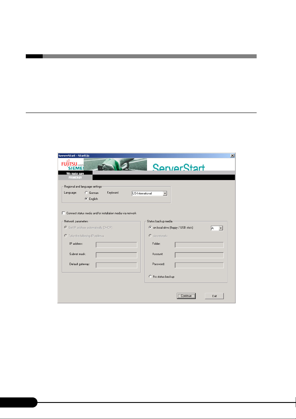
Chapter 3 OS Installation
3.2 Expert Mode
In the expert mode, start up Disk Manager, format the installation partition, and install
the OS. Use this mode only when you want to perform installation while maintaining
the existing partitions.
3.2.1 Starting Up the Expert Mode
Start up the expert mode.
1 Turn on the server and insert PRIMERGY Startup Disc immediately.
ServerStart starts up. The select-media window for the configuration file appears.
58
Page 59
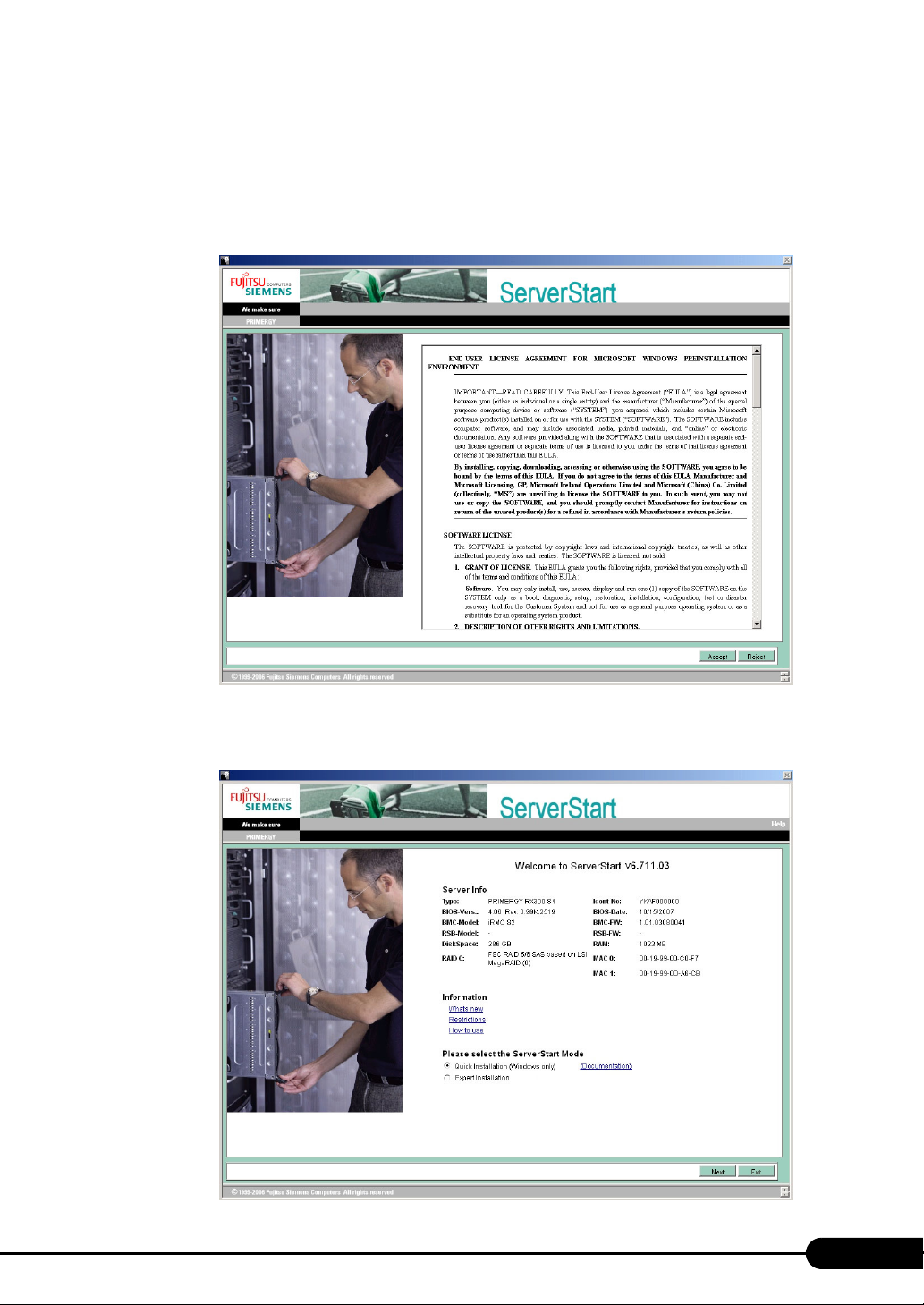
PRIMERGY TX150 S6 User’s Guide
2 Set the ServerStart floppy disk, provided with the server, and ensure that
"Removable media" and "A:" are selected. Click [Create].
The [Initialization of ServerStart core running] window appears and the ServerStart initialization
process starts. Depending on hardware configuration, this process may take a few minutes. After
completion, the license agreement window appears.
3 Click [Accept].
The [Welcome to ServerStart] window appears.
59
Page 60
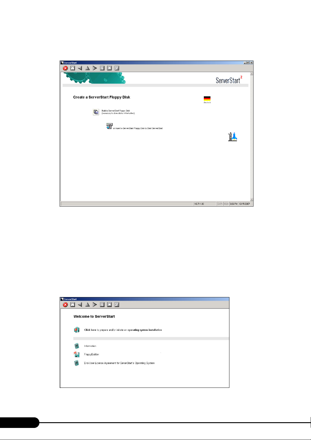
Chapter 3 OS Installation
4 Select [Expert Installation] and click [Next].
The [Create a ServerStart Floppy Disk] window appears.
5 Click [Build a ServerStart Floppy Disk].
Creation of a ServerStart floppy disk starts. When the creation is completed, the "Floppy disk has
been created." message appears.
6 Click [OK].
The [Please Select your Keyboard] window appears.
7 Select your keyboard language from the drop-down list and click [OK].
The subsequent start procedure may take several minutes.
The [Welcome to ServerStart] window appears.
60
Page 61
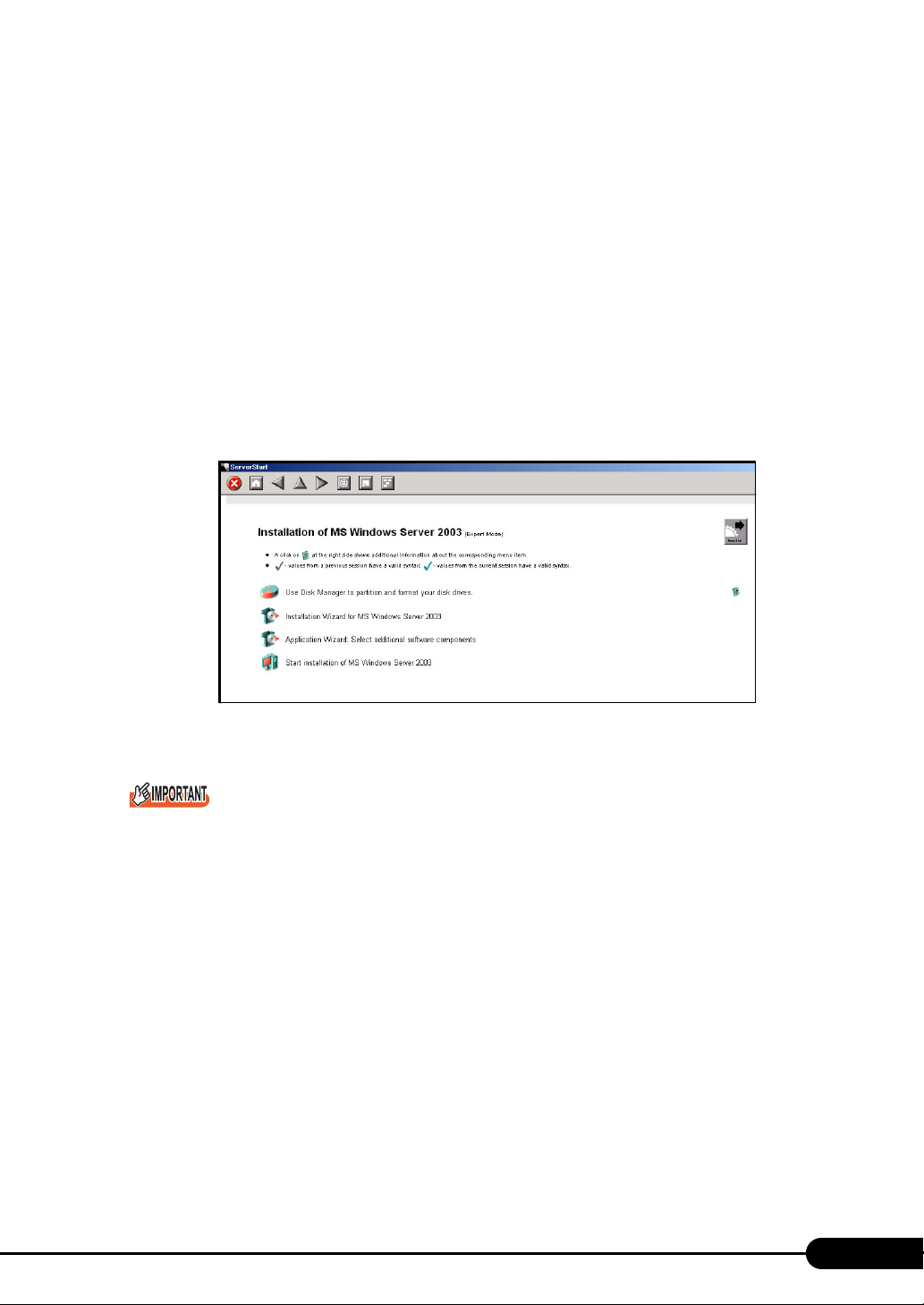
PRIMERGY TX150 S6 User’s Guide
8 Click [Click here to prepare and/or initiate an operating system installation].
The [Select the operating system to be installed] window appears.
Click [Special Hints on Operating System Installation] and observe them carefully. Important
information such as limitations on configuration of hard disk units is described.
9 Click [MS Windows Operating Systems].
The [Microsoft Windows Operating System Installation] window appears.
10 Click [Install MS Windows Server 2003 or MS Small Business Server (SBS)
2003].
The [Installation of MS Windows Server 2003] window appears.
11 Click [Install MS (OS) interactively (expertise required)].
The expert mode starts.
Start up the configuration tools to set items. Exiting a tool returns to the display to the expert
mode window.
Make sure to open the menu of each wizard and confirm the settings.
61
Page 62
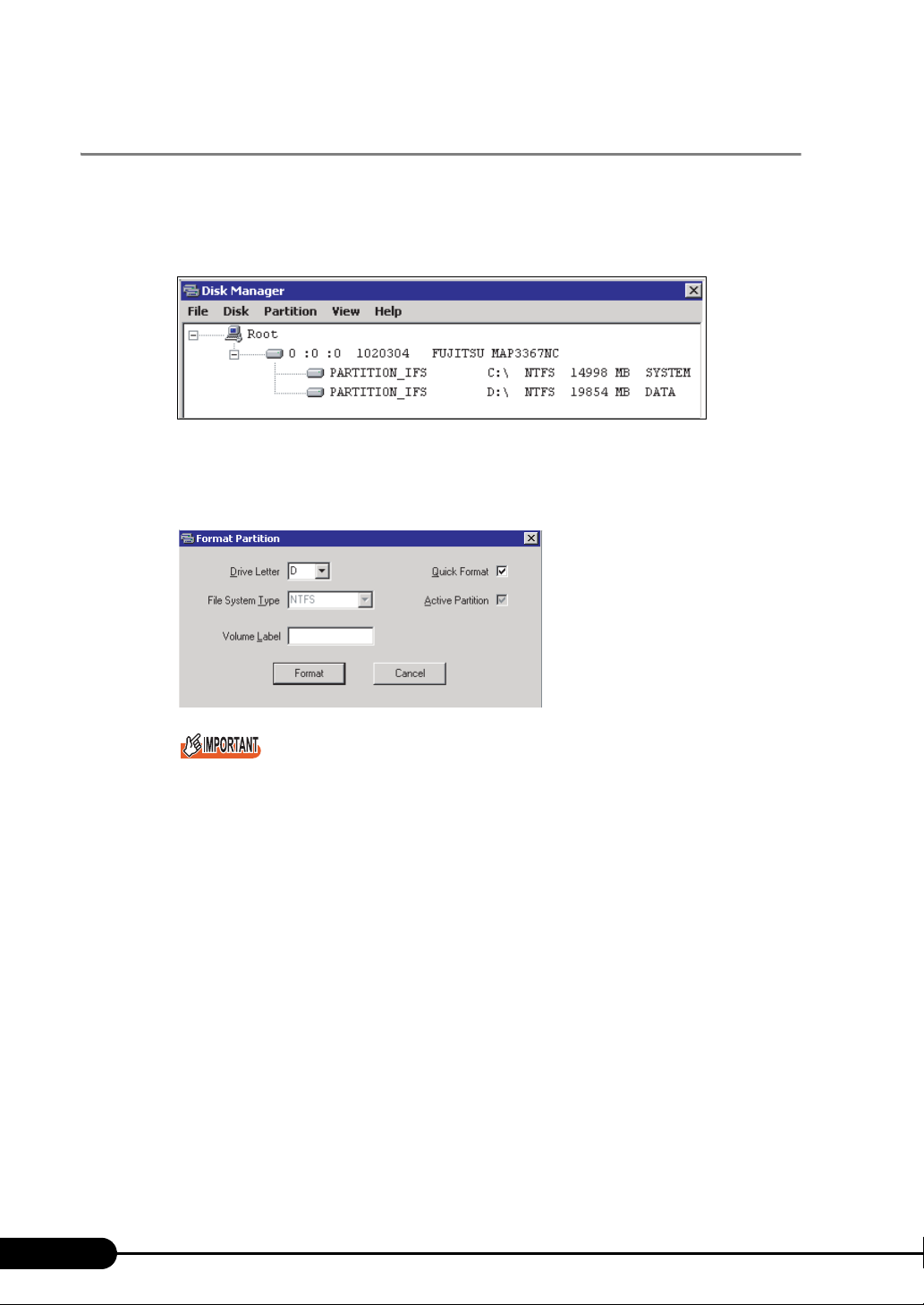
Chapter 3 OS Installation
3.2.2 Disk Manager
Start up Disk Manager and format the installation partition.
1 Click [Use Disk Manager to partition and format your disk drives].
Disk Manager starts up.
2 Format the OS installation partition. Select the OS installation partition and click
the [Partition] menu – [Format].
The [Format Partition] window appears.
62
Be sure to set the active partition on drive C.
3 Set items and click [Format].
The partition is formatted.
4 When the formatting is completed, click the [File] menu – [Exit].
Disk Manager closes and the display returns to the expert mode window.
Page 63
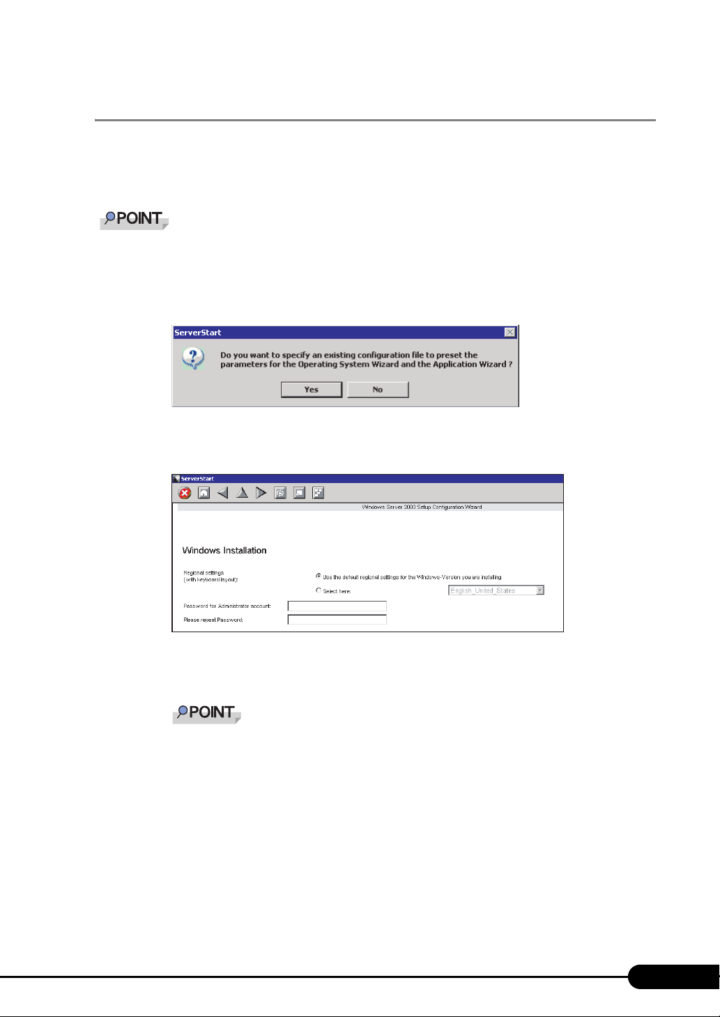
PRIMERGY TX150 S6 User’s Guide
3.2.3 OS Installation Wizard
Set computer information, user information, and the network protocol.
ServerStart can configure multiple network patterns. When configuring a domain controller, refer to
"Using ServerStart to Configure the Network".
The setup windows vary depending on the OS to be installed. For example, operation on Server 2003
R2 is given below. Server 2003 R2 is corresponding to your OS to be installed.
1 Click [Installation Wizard for MS Windows Server 2003].
A message prompts you to specify the configuration file.
2 Click [No].
The [Windows Installation] window appears.
3 Enter the password in [Password for Administrator account] and [Please repeat
Password] and click [Next].
If the passwords of [Password for Administrator account] and [Please repeat Password] are
not identical, an error message occurs. Enter the password correctly.
63
Page 64
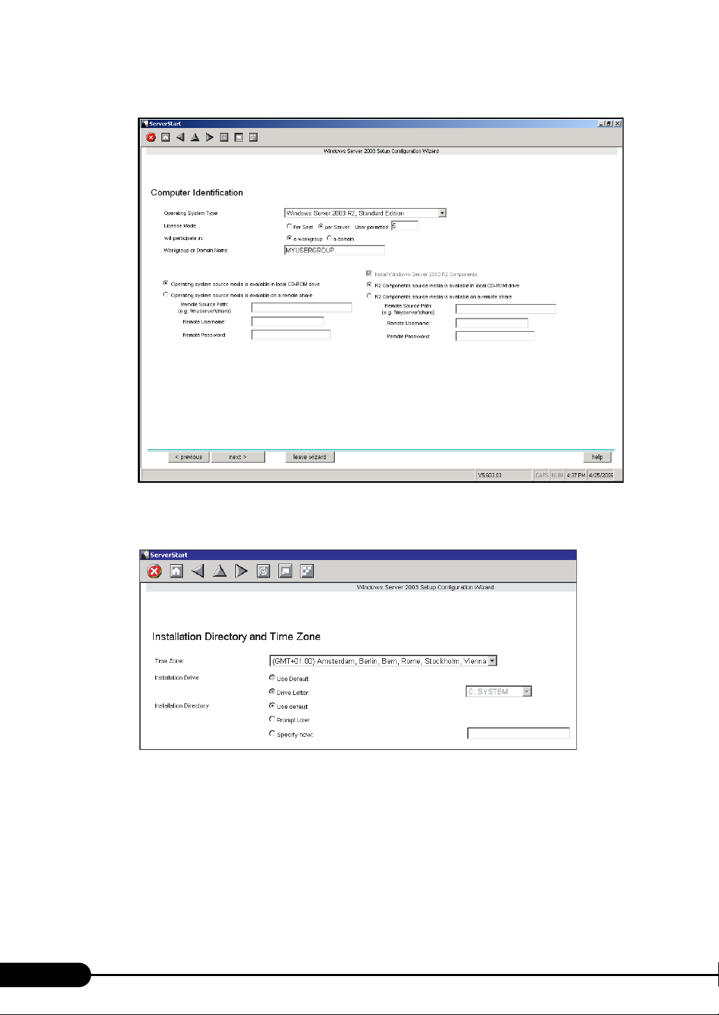
Chapter 3 OS Installation
The [Computer Identification] window appears.
4 Set items and click [next].
The [Installation Directory and Time Zone] window appears.
64
Page 65
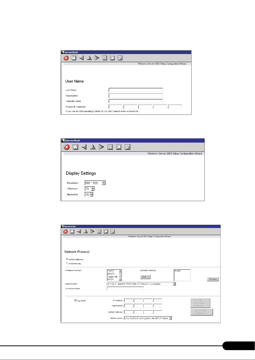
5 Set items and click [next].
The [User Name] window appears.
6 Set items and click [next].
The [Display Settings] window appears.
PRIMERGY TX150 S6 User’s Guide
7 Set items and click [next].
The [Network Protocol] window appears.
65
Page 66
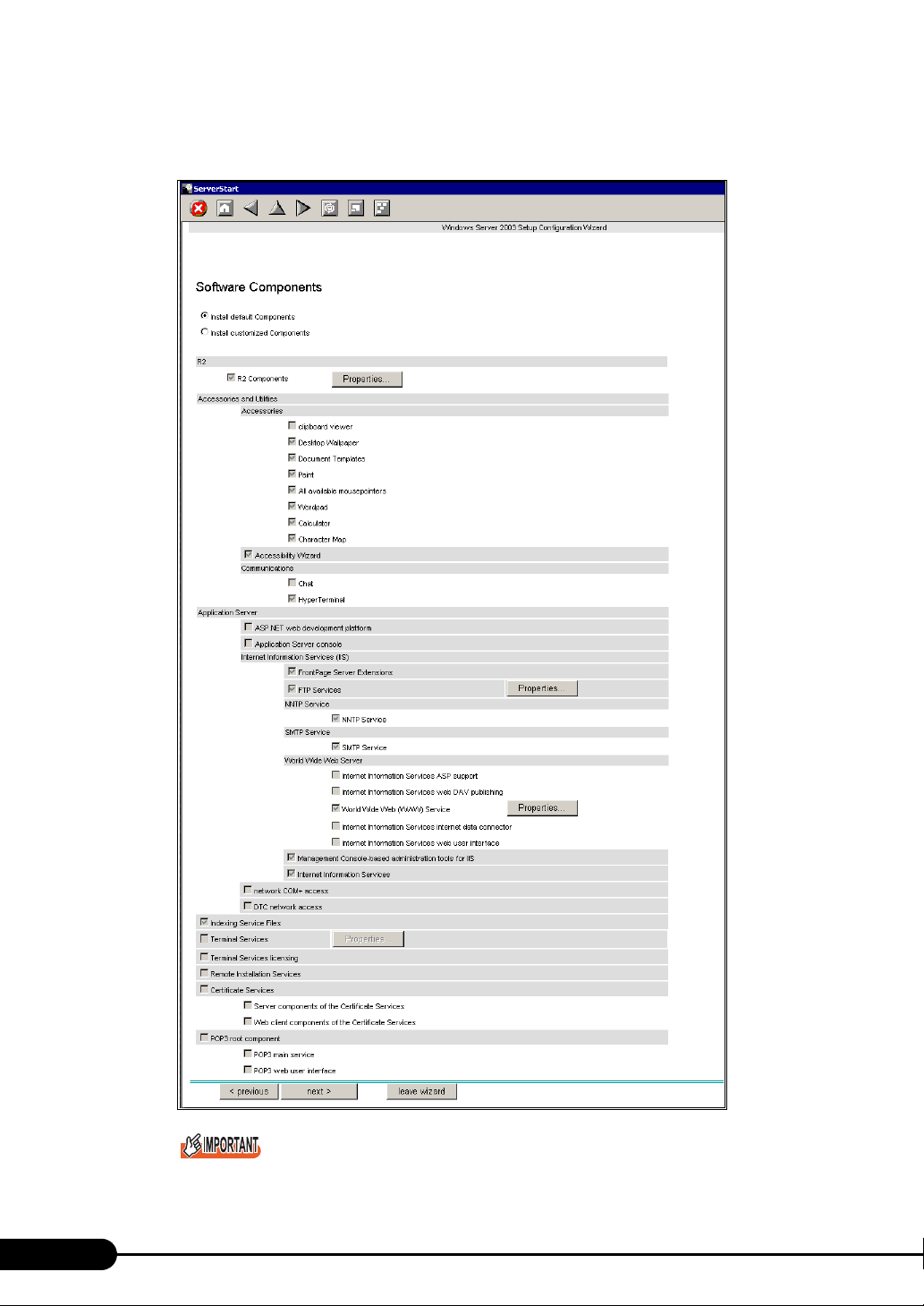
Chapter 3 OS Installation
8 Set items and click [next].
The [Software Components] window appears.
66
If Windows Server 2003 R2 is selected at the Computer Identification, R2 components are
always copied to the hard disk. To install the components, click [Properties] and check the box
of the components to be installed.
Page 67
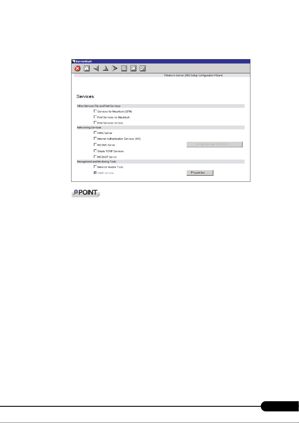
9 Set items and click [next].
The [Services] window appears.
PRIMERGY TX150 S6 User’s Guide
Simple Network Management Protocol is always installed. Click [Properties] to change the set-
tings.
10 Set items and click [leave wizard].
The display returns to the expert mode window.
67
Page 68
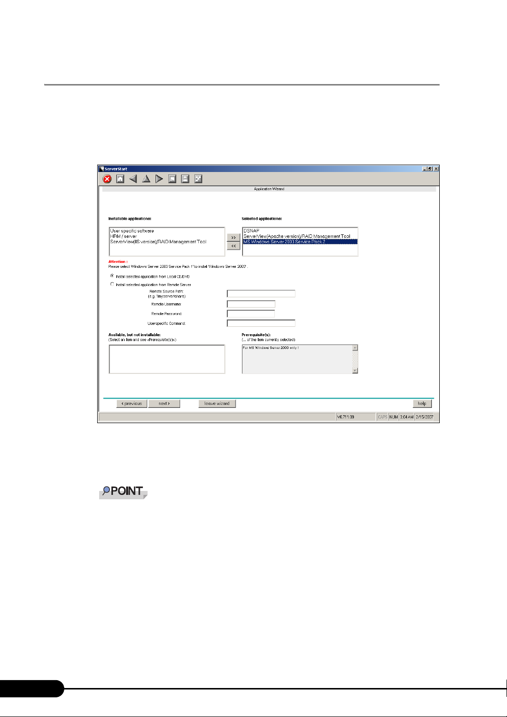
Chapter 3 OS Installation
3.2.4 Application Wizard
Set configurations for installation of supplied applications such as high reliability tools. Open those
windows and confirm the settings carefully.
1 Click [Application Wizard: Select additional software components].
The application wizard appears.
68
2 From the list in [Installable applications], select application software to be
installed and click [>>].
Set all applications to be installed on the [Selected applications] list.
Although the selection can be released in the expert mode, it may take a long time to restore
the system when errors occur without the management tools. Be sure to install these tools.
•DSNAP
• Broadcom Advanced Control Suite
• RAID Management Tool
• ServerView (Apache)
• ServerView (IIS)
Only Service Pack 2 is available to perform automatic installation with ServerStart.
3 Click [leave wizard].
The application wizard closes.
Page 69
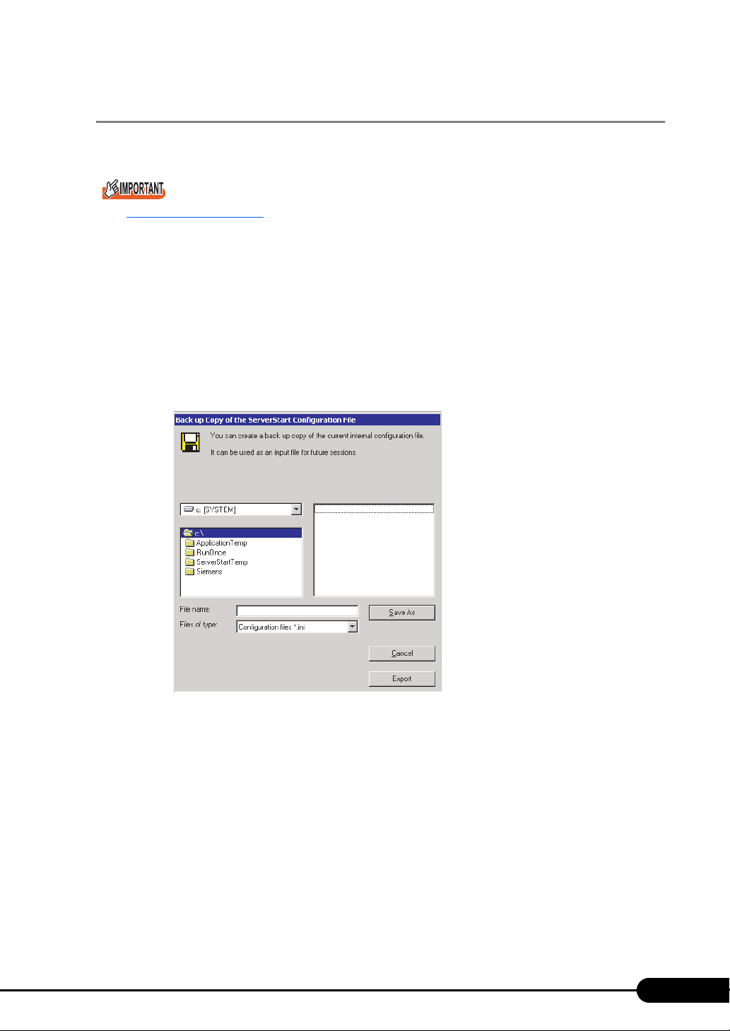
3.2.5 Starting OS Installation
Install the operating system to the server.
Notes on the installation
When the installation partition is not empty, a confirmation message appears. Unless otherwise
considered as problem, click [OK] to continue the installation procedure.
If an incorrect setting (such as the CD key) is found during installation, an error window will appear.
Enter the correct values in the window to continue the installation procedure. However, corrections
made here are not reflected on the configuration file.
1 Click [Click here, to Start the Installation of (OS)].
A confirmation window asking whether you want to save the current settings appears.
2 Click [Yes].
The following window appears.
PRIMERGY TX150 S6 User’s Guide
3 Enter the file name and click [Save As].
Installation starts automatically.
1. If a message prompts you to insert Array Controller Document & Tool CD, insert
the CD-ROM and click [OK].
2. If a message prompts you to insert the Service Pack CD-ROM, insert the CD-ROM
and click [OK].
3. For Server 2003 x64, a message prompts you to insert Startup Disc Win64 and
restart the system. Insert the Startup Disc Win64.
69
Page 70
Chapter 3 OS Installation
4 When a message prompts you to insert the OS CD/DVD, insert the CD/DVD
and click [OK].
For Windows Server 2003 / Windows Server 2003 x64
1. Insert the OS CD/DVD (Installation disc).
The license agreement window appears.
2. Click [I agree].
After files are copied, a message prompts you to eject the CD/DVD and floppy disk.
For Windows Server 2003 R2 / Windows Server 2003 R2 x64
1. Insert the OS CD/DVD (Installation disc) Disc 1.
The license agreement window appears.
2. Click [I agree].
After files are copied, a message prompts you to insert the Disc 2.
3. Insert the Disc 2 of OS CD/DVD (Installation disc).
After files are copied, a message prompts you to eject the CD/DVD and floppy disk.
5 Eject the CD/DVD and floppy disk and click [OK].
The system is restarted. The system continues the installation operation after restart.
Setup of OS GUI and installation of LAN utility, Service Pack, and Active Directory are
performed automatically.
When SATA hard disk has been installed, the massage appears that SATA HDD is detected.
Click [OK] and proceed to the operation.
6 When a confirmation message to restart appears, click [Restart].
The system restarts and installs high reliability tools.
Thus the Command Prompt windows may appear and disappear during installation of Sever-
View, the installation process is properly proceeding.
7 Press any key when a message notifies completion of installation.
8 Restart the system.
Click [Start] – [Shutdown]. Select [Restart] and click [OK].
The system restarts.
9 Perform the settings for the RAID management tool (ServerView RAID).
For the setting procedures, refer to the manuals in Array Controller Document & Tool CD.
• Settings of an array administrator account
The Windows user account is required when using ServerView RAID. Create a group named
"raid-adm", and an account with any name for an array administrator within the group "raid-
adm".
• Configuration of HDD Check Scheduler
Modify the settings of HDD Check Scheduler if necessary when using a SAS array controller
card (MegaRAID SAS) and Onboard Software RAID (Embedded MegaRAID SATA). It has
been set at 12 o’clock everyday as a default setting.
70
Page 71
PRIMERGY TX150 S6 User’s Guide
• Configuration of Battery Recalibration Scheduler
Modify the settings of Battery Recalibration Scheduler if necessary when using a SAS array
controller card (MegaRAID SAS) together with a battery backup unit. It has been set at 11
o’clock on the first day of every month as a default setting.
The server setup and OS installation have been completed. Refer to "Chapter 4 Operations after OS
Installation" (
pg.73) and perform necessary procedures before starting server operations.
71
Page 72
Chapter 3 OS Installation
72
Page 73
Chapter 4
Operations after OS
Installation
This chapter explains the operations to be
performed after OS installation. Be sure to
perform these operations before operating the
server.
4.1 Memory Dump/Paging File Setting
4.2 Creating a Disk for System Recovery
4.3 Storing the System Configuration Information
4.4 Creating Maintenance Tools and Driver Disks
4.5 Notes before Operating the Server
4.6 LAN Driver Advanced Setup [BACS]
4.7 LAN Driver Advanced Setup [Intel® PROSet]
. . . . . . . . . . . . . . . . . . 74
. . . . . . . . . . . . . . . . 79
. . . . . . . . . . . . . . . . . 92
. . . . . . . . . . . . . . . . 95
. . . . . . . . . . 81
. . . . . . . . . 85
. . . . . . . . . . 98
73
Page 74

Chapter 4 Operations after OS Installation
4.1 Memory Dump/Paging File Setting
Before starting operating this server, configure the setting for obtaining memory
dump.
z Memory dump
Debugging information, when memory dump has been set, will be automatically saved in case that a
STOP error (fatal system error) occurs in the system. Error causes may be apparent by analyzing the
saved memory dump.
When a large-capacity memory is installed, care shall be exercised to configure the settings of the
memory dump file. The settings for obtaining memory dump should be configured after installing the
files to be used for operations (OS, applications, etc.).
4.1.1 How to Obtain Memory Dump
Check the following settings before starting configuration to obtain memory dump.
Checking hard disk free space
To obtain memory dump, sufficient hard disk capacity is required for creating paging files and memory
dump files. The obtainable dump types and required hard disk capacity are as follows:
z Complete memory (full) dump (recommended)
When the system unexpectedly stops, contents of the whole system memory are recorded. The file is
stored in the directory displayed in the [Dump file] box.
• Paging file: Installed physical memory + 11MB (Recommended: Installed physical memory × 1.5)
• Memory dump file: Equivalent to installed physical memory
Complete memory dump can not be used on the computer in which the 2GB or larger memory is
installed.
z Kernel memory dump
Information of only kernel memory space is recorded. The file is stored in the directory displayed in the
[Dump file] box. Capacity required for kernel memory dump is as follows:
• Paging file: Depending on installed physical memory amount
For memory of 256 to 1,373MB - Installed physical memory × 1.5
For memory of 1,374MB or more - 32-bit system: 2GB + 16MB, 64-bit system: Installed physical
memory + 128MB
• Memory dump file: Depending on the kernel-mode address space being used during STOP
74
Page 75
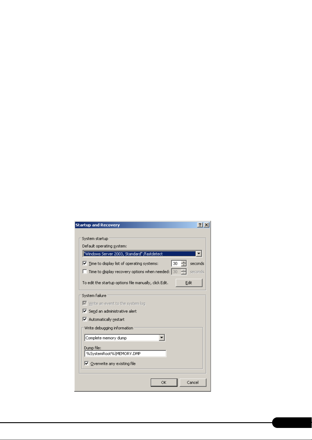
PRIMERGY TX150 S6 User’s Guide
z Small memory dump
Minimum information to identify a problem is recorded. When this option is selected, a new file is
created each time the system unexpectedly stops.
Those file histories are stored in the directory displayed in [Small dump directory].
• Paging file: Minimum 2MB
• Memory dump file: 64KB or 128KB
Memory dump file setting
Set up the memory dump file according to the following procedures:
1 Log on to the server with the administrator account.
2 Check free space of the drive where the memory dump file is to be stored.
Check the required free space according to " Checking hard disk free space" (pg.74).
If the drive has insufficient free space, refer to "
Cannot collect the memory dump" (pg.187).
3 Click [Start] – [Control Panel] – [System].
The [System Properties] window appears.
4 Click the [Advanced] tab and click [Settings] in [Startup and Recovery].
The [Startup and Recovery] window appears.
75
Page 76
Chapter 4 Operations after OS Installation
5 Set as follows:
1. In the [Write debugging information] section, select the memory dump file type.
• Complete memory dump (Recommended)
The whole system memory information is recorded to the memory dump file.
• Kernel memory dump
Only kernel memory is recorded to the memory dump file.
• Small memory dump (64KB)
Minimum information is recorded to the memory dump file.
Each time a fatal error occurs, a new file is created in the directory specified in [Small
dump directory].
2. In [Dump file] or [Small dump directory], specify the directory to save the memory
dump file, with its full path.
For kernel memory dump or complete memory dump, when check the box of the
[Overwrite any existing file], debugging information is overwritten to the specified file
every time.
6 Click [OK] to close the [Startup and Recovery] window.
7 Click [OK] to close the [System Properties] window.
8 Restart the system.
The setting is enabled after the system restarts.
Paging file setting
Set up the paging file according to the following procedures:
1 Log on to the server with the administrator account.
2 Check free space of the drive where the system has been installed.
Check the required free space according to " Checking hard disk free space" (pg.74).
If the drive has insufficient free space, refer to " Cannot collect the memory dump" (pg.187).
3 Click [Start] – [Control Panel] – [System].
The [System Properties] window appears.
4 Click the [Advanced] tab and click [Settings] in [Performance].
The [Performance Options] window appears.
76
Page 77
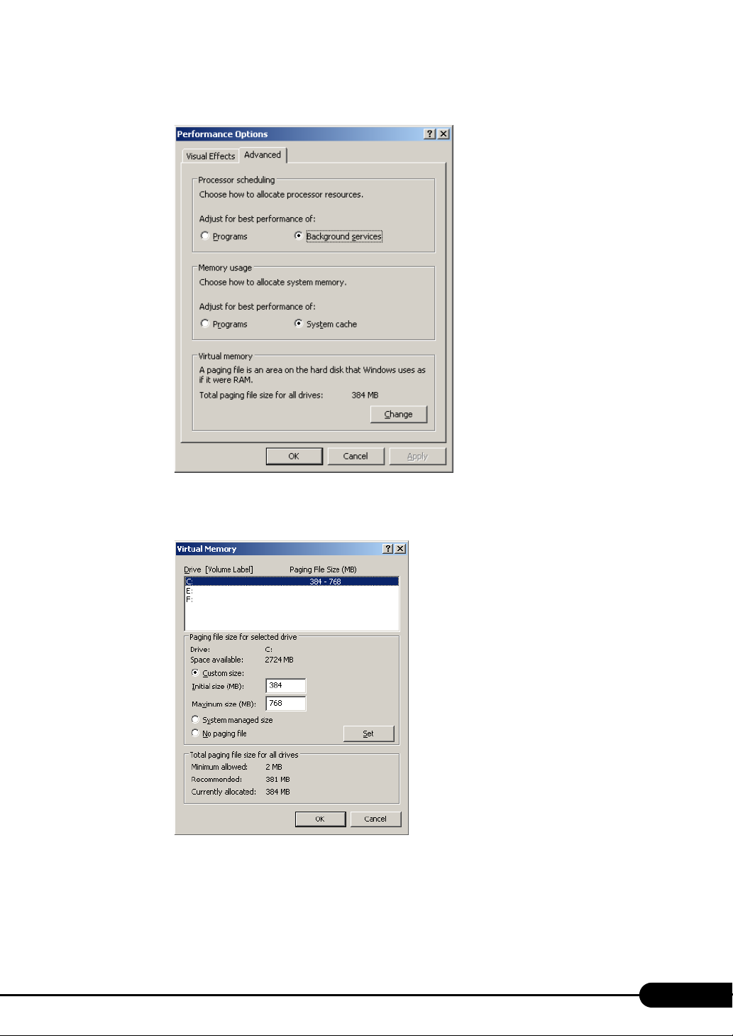
5 Click the [Advanced] tab.
PRIMERGY TX150 S6 User’s Guide
6 Click [Change] of the [Virtual memory].
The [Virtual Memory] window appears.
7 Select the drive where the paging file is to be created.
In [Drive], select the drive where the system is installed.
The selected drive is displayed in [Drive] in [Paging file size for selected drive].
77
Page 78

Chapter 4 Operations after OS Installation
8 Select [Custom size] and enter a value in [Initial size].
The value depends on the type of the set dump file.
Set a value larger than the value shown in [Recommended] in [Total paging file size for all
drives].
When a smaller value is specified for the paging file size, performance may be affected. For
maximum system efficiency, be sure to set [Initial size] with a value larger than the [Recom-
mended] size described in [Total paging file size for all drives]. The recommended size is total
memory installed in the system x 1.5. However, if a program occupies a large part of memory
is regularly used, set a larger size as required.
9 Enter a value in [Maximum size].
Set a value larger than the [Initial size].
10 Save the settings.
Click [Set] in the [Paging file size for selected drive] section.
The settings are saved, and the value specified is displayed in [Paging File Size] of [Drive].
11 Click [OK] to close the [Virtual Memory] window.
12 Click [OK] to close the [Performance Options] window.
13 Click [OK] to close the [System Properties] window.
14 Restart the system.
The setting is enabled after the system is restarted.
Rebooting after OS dump setting
Rebooting may not be executed when the server fails even if rebooting has been set after obtaining
dumping.
Immediate provision may be required when the server fails. However, configure the settings of
rebooting with the Watchdog, when continuous operation is required. For details and configuration
procedures for the Software Watchdog, refer to "3.4 Serious Error Handling (ASR)" in "ServerView
User’s Guide".
78
Page 79
PRIMERGY TX150 S6 User’s Guide
4.2 Creating a Disk for System Recovery
If the installation of the OS was performed manually, create a system recovery disk.
If the system file, system configuration, or environment setting change at startup, etc., is damaged,
such data can be reconstructed using the recovery information stored in the created system recovery
disk.
To create a recovery disk, prepare an unused formatted floppy disk.
4.2.1 Creating the Automated System Recovery (ASR) Set
After setting up Windows Server 2003, create a system recovery set. An unused formatted floppy disk
and a medium are required to store back up files.
1 Click [Start] – [All Programs] – [Accessories] – [System Tool] – [Backup].
The [Backup or Recovery Wizard] window appears.
2 Click [Next].
The [Backup or Recovery] window appears.
3 Select [Create a backup of files and settings], and then click [Next].
The [Items to Create Backups] window appears.
4 Select [All the information in this computer], and then click [Next].
The [Backup Type, Destination and Name of the Backup File] window appears.
5 Enter a name and a destination of the backup file, and then click [Next].
The [Backup or Recovery Wizard Complete] window appears.
6 Click [Finish].
Backup process starts.
7 If a message prompts you to insert a floppy disk, insert the floppy disk and click
[OK].
Automated system recovery disk is created.
8 When the process is completed, a message appears. Eject the floppy disk
according to the message and put a label on it.
Label Example: "Windows Automated System Recovery Disk: Backup.bkf, Created at 12:00 04/
01/2003"
79
Page 80
Chapter 4 Operations after OS Installation
9 Click [OK] to exit [Backup Utility].
10 Click [Close] to close the [Backup Progress] window.
An automated system recovery set has been created.
Store the automated system recovery set just created for sure.
80
Page 81
PRIMERGY TX150 S6 User’s Guide
4.3 Storing the System Configuration Information
Before starting operations and when changing the system configuration information,
store the configuration information. By storing this information, the system can be
recovered with the stored information in case of a system failure (such as when the
baseboard fails). Use Server Management Tools for storing and recovering the
system configuration information.
Since the system configuration information is significant in maintaining the server, be sure to store the
configuration information after the following operations:
• When the information is changed with the BIOS Setup Utility
• When the hardware configuration of this server is changed (e.g. memory, hard disk unit, baseboard
or expansion card is added/removed or changed)
• When the Remote Management Controller information is changed
As the stored system configuration information will be used for maintenance operation.
Cautions
• "Server Management Tools" disk is exclusively for this server. Do not use it on other systems.
Otherwise, the systems may be damaged.
• Only the information that is configured with BIOS Setup Utility and the configuration information of
the Remote Management Controller can be stored/recovered. However, a user account for the
Remote Management Controller and the license information of the Remote Management Ctrl
Upgrade kit cannot be stored.
• Make sure to perform this operation only when the server is started with the "Server Management
Tools" disk. Do not run Server Management Tools on the server started from the hard disk or by the
other floppy disk. Otherwise, the system may be damaged.
• Do not eject a floppy disk while the floppy disk access LED is on. Such an action may lead not only
to corruption of the floppy disk data but also an unstable state of the system.
• If an error message appears while running Server Management Tools, respond to the message
according to "
Server Management Tools error messages" (pg.184).
Creating Server Management Tools disk
Server Management Tools disk is required to be created when stated as "blank" on the label of the
"Server Management Tools" disk supplied with the server. Create Server Management Tools by referring
to "4.4 Creating Maintenance Tools and Driver Disks" (
pg.85).
81
Page 82
Chapter 4 Operations after OS Installation
4.3.1 Storing the BIOS Information and the Remote Management Controller Information
Store the BIOS information and the Remote Management Controller information according to the
following procedures.
Before starting the operation, if the "OS Boot Monitoring" function of ServerView is enabled, disable it
(it is disabled by default). If you start up the system while the "OS Boot Monitoring" function remains
effective, the operation of the server may become unpredictable at such times as an abrupt power
interruption or restart.
If it is necessary to operate the server with the "OS Boot Monitoring" function enabled, enable the
function after storing the BIOS/Remote Management Controller information. For details of ServerView,
refer to "ServerView User’s Guide".
Server Management Tools disk is required to be created when mentioned as empty "blank" on the
label of the "Server Management Tools" disk, supplied with the server. Create Server Management
Tools by referring to "4.4 Creating Maintenance Tools and Driver Disks" (pg.85).
1 Insert the Server Management Tools disk into the floppy disk drive and turn on
the server.
The window for selecting a keyboard appears.
Please select:
1 = JP Keyboard
2 = US Keyboard
Your selection
2 Select a keyboard.
Select [1] for Japanese keyboard or select [2] for English keyboard. Japanese keyboard is
selected by default.
3 When the DOS Prompt window appears, enter the following command and
press the [Enter] key.
A:\SMT>BIOSSAVE.bat
Do not input the file extension at the end of a file name.
The file name is given as "cmosfile" when a file name is not input.
4 If the BIOS information or the Remote Management Controller information is
stored successfully, the following message appears.
Success !
82
Page 83
PRIMERGY TX150 S6 User’s Guide
5 Confirm that the stored information files are created.
Enter the following command to display the stored information files which are created.
A:\SMT>dir
The BIOS information has been stored. The server can now be turned off safely.
4.3.2 Recovering the BIOS / Remote Management Information
If the information configured with BIOS Setup Utility was deleted due to a drain of the built-in server
battery, etc., restore the BIOS information according to the following procedures.
Do not turn off the server while a program is running.
Before starting up the system, check that the "OS Boot Monitoring" function of ServerView is disabled
(it is disabled by default).
If you start up the system while the "OS Boot Monitoring" function remains effective, the operation of
the server may become unpredictable at such times as an abrupt power interruption or restart. If the
server is operated with the "OS Boot Monitoring" function enabled, enable the function again before
resuming operation. For details of ServerView, refer to "ServerView User’s Guide".
Server Management Tools disk is required to be created when mentioned as empty "blank" on the
label of the "Server Management Tools" disk, supplied with the server. Create Server Management
Tools by referring to "4.4 Creating Maintenance Tools and Driver Disks" (pg.85).
1 Insert the Server Management Tools disk into the floppy disk drive and turn on
the server.
The window for selecting a keyboard appears.
Please select:
1 = JP Keyboard
2 = US Keyboard
Your selection
2 Select a keyboard.
Select [1] for Japanese keyboard or select [2] for English keyboard. Japanese keyboard is
selected by default.
3 When the DOS Prompt window appears, confirm that the BIOS stored
information files are in the floppy disk.
Enter the following command to confirm that the stored information files are in the floppy disk.
A:\SMT>dir
4 Enter the following command and press the [Enter] key.
A:\SMT>BIOSRESET.bat
83
Page 84
Chapter 4 Operations after OS Installation
Do not input the file extension at the end of a file name.
The file name is given as "cmosfile" when a file name is not input.
5 If the BIOS information is restored correctly, the following message appears.
Success !
6 The BIOS information will be enabled after the next system restart. Restart the
server.
Perform Step 1 to display the DOS Prompt window. The restoration procedure has been
completed. The server can now be turned off safely.
84
Page 85
PRIMERGY TX150 S6 User’s Guide
4.4 Creating Maintenance Tools and
Driver Disks
This section explains how to create the server maintenance tools and driver disks
with FloppyBuilder function of ServerStart.
With FloppyBuilder function of ServerStart, you can create the following tools:
• Server Management Tools disk
• DOS Diskette
FloppyBuilder can be used under environments such as:
• The ServerStart system started on a client computer (recommended)
• The ServerStart system started from PRIMERGY Startup Disc on the server
When creating the tools on a client computer, it is necessary to install ServerStart on the client
computer beforehand.
If ServerStart of a different version is installed on the computer, make sure to uninstall the ServerStart.
Then perform installation again. For details on how to uninstall ServerStart, refer to "
ServerStart" (pg.87).
Uninstalling
4.4.1 Installing ServerStart
Install ServerStart on a client computer when creating a drive disk using FloppyBuilder function.
z System requirements for client computers
Client computers must satisfy the following requirements.
Hardware Personal computers operated with Windows Vista, Windows XP Professional,
Software
Using ServerStart on the server
ServerStart can be installed to the server, when using Windows Server 2003. Install ServerStart in
accordance with this chapter.
Note that ServerStart is not available to the server where Windows Server 2003 x64 is installed.
1 Insert the PRIMERGY Startup Disc into the client computer.
or Windows 2000 Professional
(A DVD drive and minimum 10MB free disk space are required.)
Microsoft
The [PRIMERGY Startup Disc] window appears.
®
Internet Explorer 5.5 or later
85
Page 86
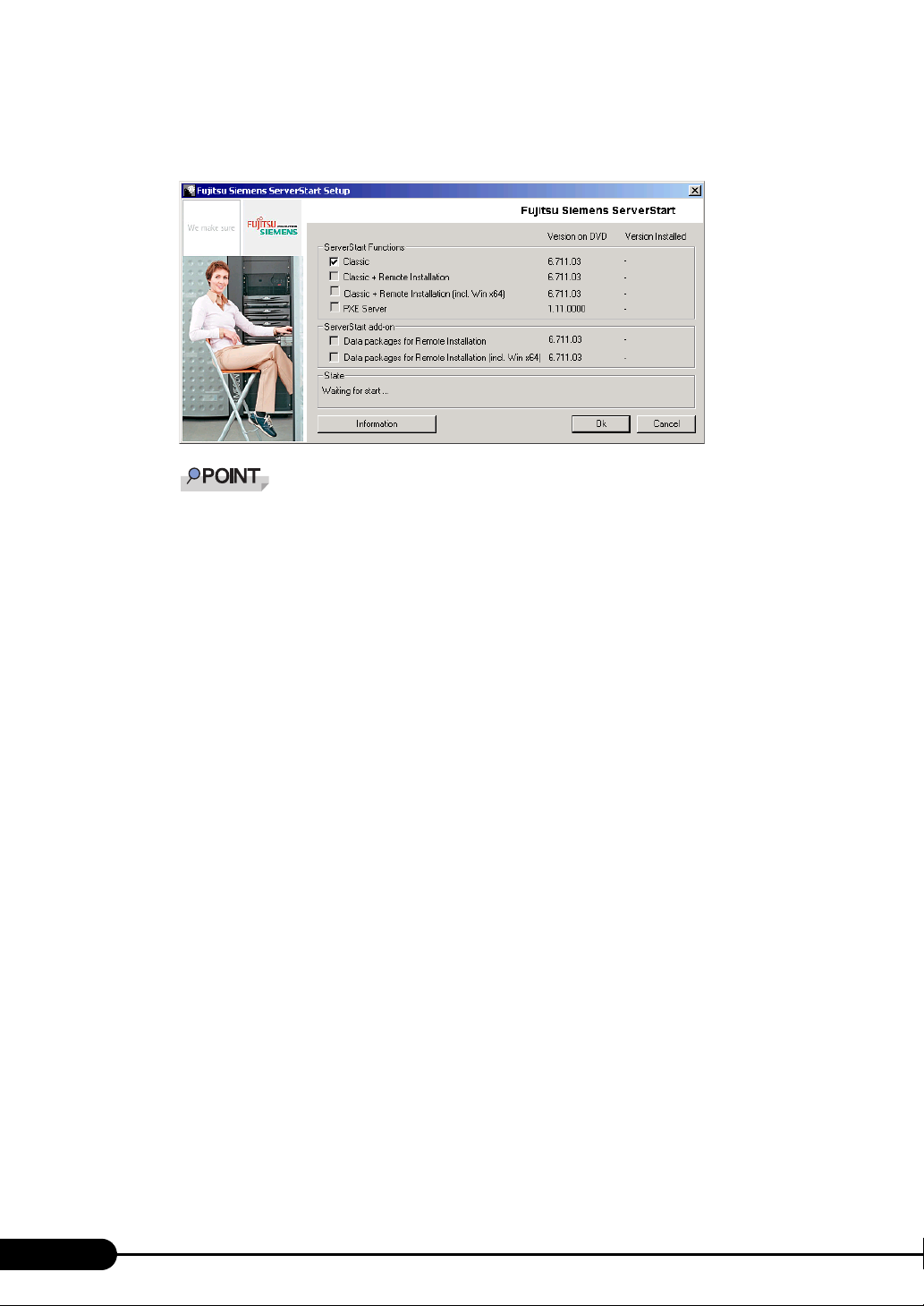
Chapter 4 Operations after OS Installation
2 Click [ServerStart V6.711].
[Fujitsu Siemens ServerStart] window appears.
The massage "Do you want to run or save this file?" may appear depending the OS in use. Fol-
low as below.
1. Click [Run].
A massage appears that "The publisher could not be verified. Are you sure you want to
run this software?"
2. Click [Run].
Execute "SeStSetup.exe" in the disk when [Fujitsu ServerStart Setup] window does not
display.
3 Check the checkbox of [Classic] only and click [OK].
The Setup window appears.
4 Click [Next].
The [License Agreement] window appears.
5 Select [I accept the license agreement] and click [Next].
The [User Information] window appears.
86
Page 87
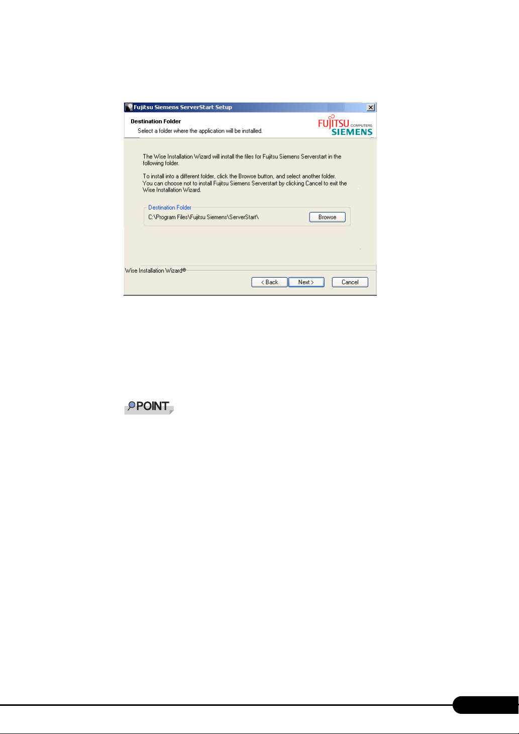
PRIMERGY TX150 S6 User’s Guide
6 Enter the user information of the software and click [Next].
The [Destination Folder] window appears.
7 Specify the installation folder and click [Next]. To change the installation folder,
click [Browse] and select the folder.
The [Ready to Install the Application] window appears.
8 Click [Next].
Installation is executed.
If a message prompts you to restart the system before or after installation, eject the disc and
restart the system according to the message. When the system restarts, insert PRIMERGY
Startup Disc and start installation again.
If the "This program does not respond." message appears during restart operation, click [Exit]
to continue the restart operation.
When the installation is completed, the completion window appears.
9 Click [Exit].
ServerStart has been installed to the client computer.
Uninstalling ServerStart
Uninstall ServerStart on the client computer according to the following procedure when necessary.
1 Click [Start] – [All Programs] – [Fujitsu Siemens ServerStart] – [Uninstall
ServerStart].
2 Click [OK].
When the uninstallation is executed successfully, ServerStart is deleted.
87
Page 88
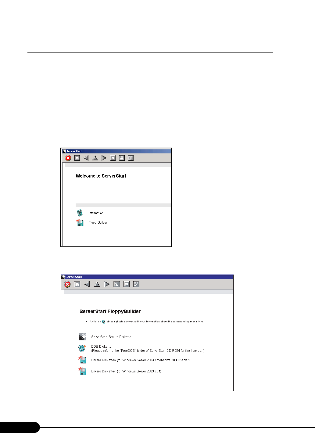
Chapter 4 Operations after OS Installation
4.4.2 Startup Method for FloppyBuilder
Start up ServerStart and FloppyBuilder. Startup methods vary depending on the cases of creating on a
client server, or the server.
z For creation on a client computer
1 Set the PRIMERGY Startup Disc to the client computer.
Once "PRIMERGY Startup Disc" window appears, exit the window.
2 Click [Start] – [All Programs] – [Fujitsu Siemens ServerStart] – [ServerStart
(Start from DVD)].
ServerStart starts up and the [Welcome to ServerStart] window appears.
88
3 Click [FloppyBuilder].
The [ServerStart FloppyBuilder] window appears.
Page 89
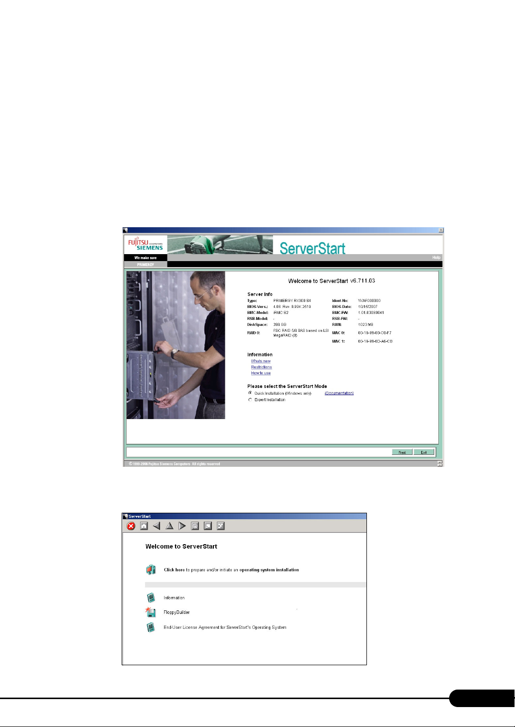
PRIMERGY TX150 S6 User’s Guide
z For creation on the server
1 Turn on the power of the server and set PRIMERGY Startup Disc.
ServerStart starts up and select media window for the configuration file appears.
2 Select [RAM Disk] and click [Next].
The [Initialization of ServerStart core running] window appears and the initialization operation
launches. In some cases, initialization operation may take a few minutes depending on hardware
configuration. After completion, the license agreement window appears.
3 Click [Accept].
The [Welcome to ServerStart] window appears.
4 Select [Expert Installation] and click [Next].
The [Welcome to ServerStart] window appears.
89
Page 90
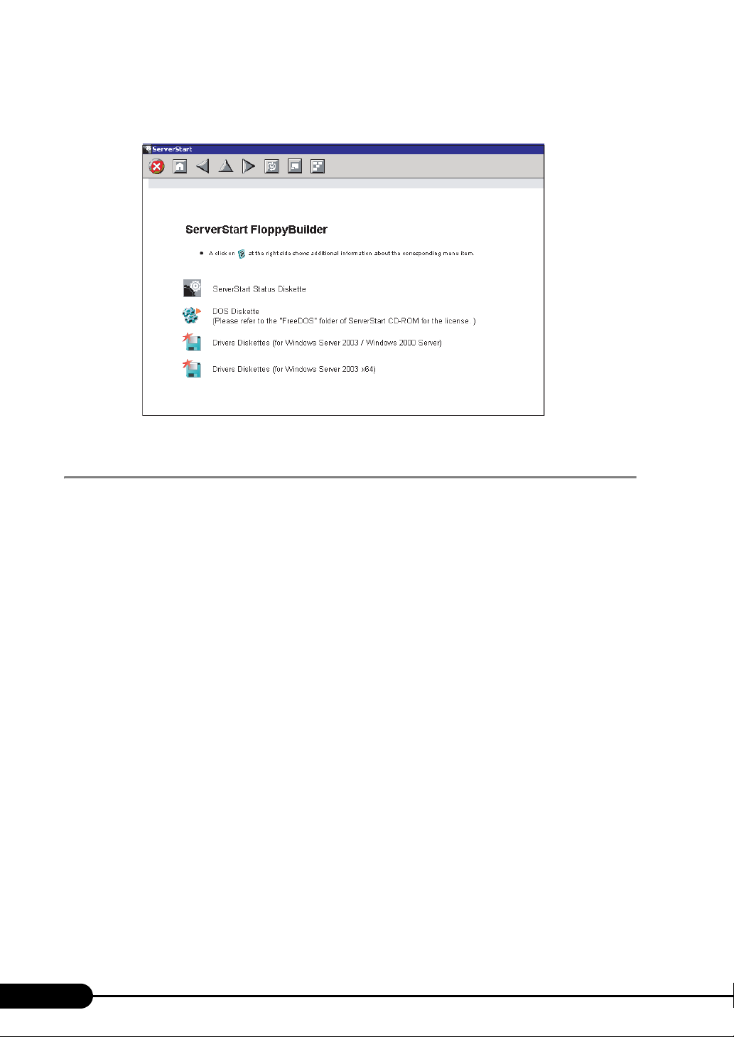
Chapter 4 Operations after OS Installation
5 Click [FloppyBuilder].
The [ServerStart FloppyBuilder] window appears.
4.4.3 Creating Server Management Tools Disk
Start up ServerStart and confirm that the FloppyBuilder window is displayed.
1 Click [Server Management Tools].
2 Click the tool to be created.
Insert the prepared floppy disk by following the message.
3 Perform the subsequent operations according to the messages on the window.
The floppy disk will be formatted automatically and file copying will start.
The respective tools will be created automatically. When a message appears indicating that the
disk is created, click [OK] and eject the disk.
4 Fill the following items on the label of the floppy disk.
• The model of the server
• Version and Level of the Server Management Tools
• Date of the floppy disk created
90
Page 91

PRIMERGY TX150 S6 User’s Guide
4.4.4 Creating Driver Disks
Obtain floppy disks as many as the number of the drivers to be created before taking the procedures
below. Start up ServerStart and confirm that the FloppyBuilder window is displayed.
1 Click [Drivers Diskettes (for Windows Server 2003 / R2)] or [Drivers Diskettes
(for Windows Server 2003 x64 / R2 x64)] according to the installed OS.
The [FloppyBuilder Driver Disk] window appears.
2 Click the type of the driver to be created.
3 Click the driver disk to be created.
Follow the message and insert a floppy disk.
4 Perform the subsequent operations according to the messages on the
windows.
The floppy disk will be formatted automatically and file copying will start.
The driver disk is automatically created. When a message appears indicating that creating the
disk is completed, click [OK] and eject the floppy disk.
4.4.5 Creating a DOS Diskette
For DOS data stored into the floppy disk, refer to the file in the following folder of the PRIMERGY
Startup Disc.
[CD/DVD drive]:\FreeDOS
To create a DOS diskette, prepare an unused floppy disk.
Start up ServerStart and confirm that the FloppyBuilder window is displayed.
1 Start up ServerStart and Click [FloppyBuilder].
2 Click [DOS Diskette].
3 Perform the subsequent operations according to the messages on the window.
The floppy disk will be formatted automatically and file copying will start.
The DOS diskette will be created automatically. When a message appears indicating that the disk
is created, click [OK] and eject the disk.
91
Page 92
Chapter 4 Operations after OS Installation
4.5 Notes before Operating the Server
This section explains the settings required before starting to operate the server. For
details on the settings, refer to the following URL.
http://www.microsoft.com/technet/prodtechnol/exchange/2003/Library/default.mspx
For the settings of the installed application software supplied with the server, refer to the manuals of
each of them.
For notes on the ServerView security, refer to "Security" in "1.1.7 Notes" in the "ServerView User’s
Guide".
4.5.1 Auto-run Function from CD/DVD Drives
Perform the following procedures to change the settings of the auto-run function from the CD/DVD
drives after server installation.
1 Make the registry editable, and change the value of AutoRun of the following
registry key:
HKEY_LOCAL_MACHINE\System\CurrentControlSet\Services\CDRom
Set the value of AutoRun to "1" to enable auto-run, or to "0" to disable auto-run.
2 Restart the system.
The setting is enabled after the system restarts.
4.5.2 Drive Letter Assignment in the Expert Mode
In the expert mode, assignment of a drive letter to a particular partition arbitrarily is not available. Drive
letters specified on Disk Manager in the expert mode will be sequentially assigned from the first
partition with "C, D, E..." when installation is completed, and an unused drive letter will be assigned to
the CD/DVD drive. When you change the drive letter, perform the following procedures after
installation.
92
The drive letters for the system and boot drive is not changeable.
Page 93
PRIMERGY TX150 S6 User’s Guide
1 Click [Start] – [Administrative Tools] – [Computer Management].
2 Click [Disk Management].
3 Right-click the partition to change the letter and click [Change Drive Letter and
Path].
The [Change Drive Letter and Path] window appears.
4 Click [Edit].
The [Change Drive Letter or Path] window appears.
5 Change the drive letter.
4.5.3 Notes on Advanced Uninterruptible Power Supply (UPS)
Note the following cautions when using an advanced uninterruptible power supply (referred to as UPS
herein).
UPS shutdown time setting
Set a sufficient time interval of UPS power-off time (time from the shutdown command to the actual
power-off). If the interval is not adequate, the power will be cut off before system shutdown. It may
cause data collapse. For details, refer to the manuals of UPS and the UPS management software.
Power supply control by UPS
Change the BIOS settings to turn on the server automatically at power recovery or during scheduled
operation using the UPS management software (PowerChute Network Shutdown and PowerChute
Business Edition).
1 Start BIOS Setup Utility.
"7.2.1 Starting and Exiting BIOS Setup Utility" (pg.149)
2 Click the [Power] menu and set [Power Failure Recovery] to [Always On].
"7.2.10 Power Menu" (pg.162)
3 Save the changes and exit BIOS Setup Utility.
93
Page 94
Chapter 4 Operations after OS Installation
4.5.4 Turning the Power On via a LAN
You can turn the power on the server from a client (via a LAN) by utilizing the Wakeup on LAN (WOL)
function.
Be sure to install ServerView to control the power supply via a LAN.
When the power cable is disconnected from the server or the server is powered off due to power
interruption, restart the server. Unless otherwise, the WOL function will be disabled.
Only the onboard LAN is available to correspond to the WOL function for this server. To control power
supply via a LAN, connect the onboard LAN and set the onboard LAN adapter bind to "1" for sure.
BIOS Setup Utility setting
When performing power management via a LAN, set [Enabled] in the [LAN] item of the power menu in
BIOS Setup Utility. The [Enabled] in the [LAN] has been set as the initial setting.
4.5.5 Other Notes on Operation
Unnecessary files
After OS installation is completed, folders named Runonce and Runonce2 may be left in the drive where
the OS has been installed. Delete these folders since those are not necessary for the system operation.
Automated system operation
When performing automated system operation, enhancement of the safety operation with this server
against unexpected accidents is necessary, employing such measures as introducing disaster-prevention
provisions and stationing responsible for disaster prevention (such as a security guard or janitor) in the
building.
Unintentional power-off prevention
It is recommended to employ a dedicated power supply device (such as a power distribution board) to
prevent accidental power shut-offs.
94
Page 95
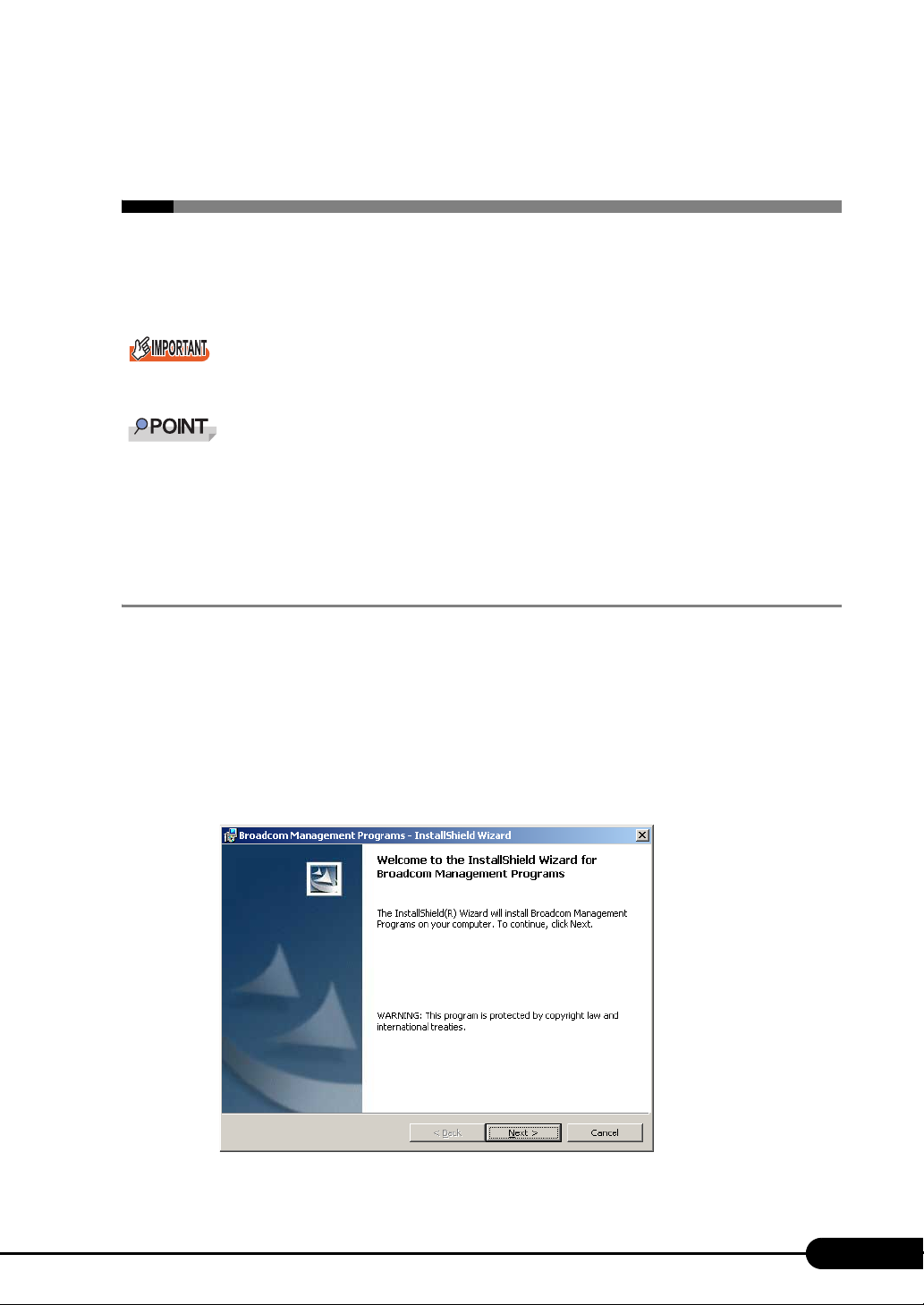
PRIMERGY TX150 S6 User’s Guide
4.6 LAN Driver Advanced Setup
[BACS]
BACS is an integrated GUI application software. Use BACS to perform advanced
settings of onboard LAN.
VLAN is not available using together with onboard LAN.
Use Intel® PROSet (pg.98) to perform the following advanced setups of a LAN card:
• Use the Teaming function between LAN cards or between a LAN card and the onboard LAN
• Setup a VLAN using a LAN card
• Perform the other advanced settings of a LAN card
4.6.1 BACS Installation
If [Broadcom Control Suite 2] is not displayed in the [Control Panel], install BACS according to the
following installation procedures:
For Windows Server 2003 x64
1 Start up the following file contained in the PRIMERGY Startup Disc.
[CD/DVD drive]:\PROGRAMS\General\Broadcom\MgmtApps_x64\setup.exe
The installer starts up.
95
Page 96
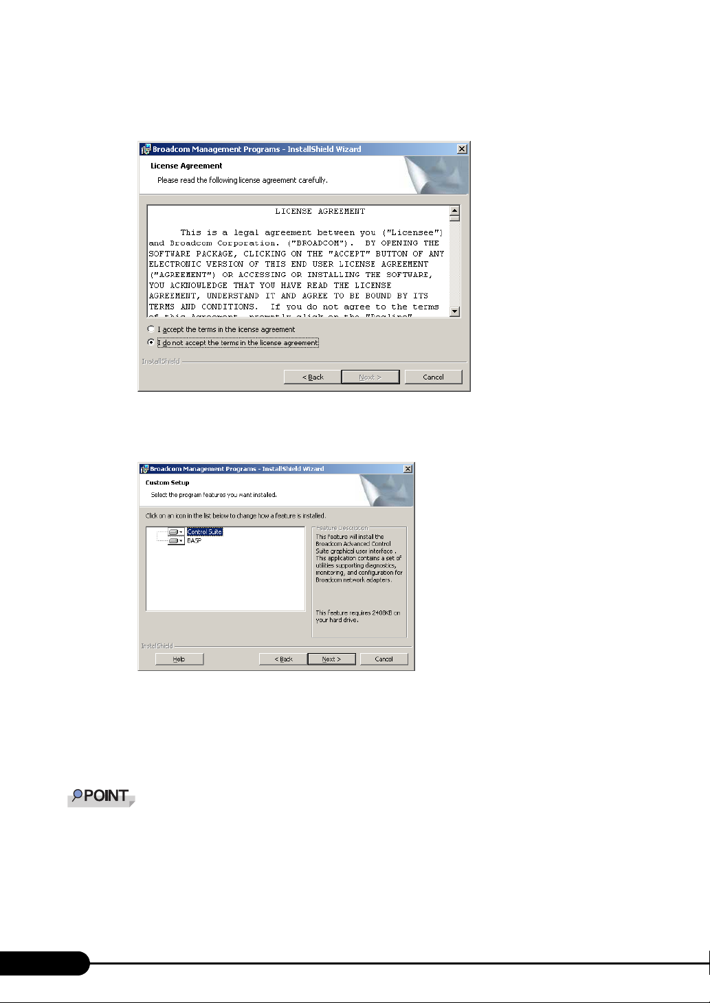
Chapter 4 Operations after OS Installation
2 Click [Next].
The license agreement window appears.
3 Click [I accept the terms in the license agreement] and click [Next].
The [Custom Setup] window appears.
4 Click [Next].
Proceed to the installation by following the window instructions.
For Windows Server 2003
If the OS is installed using ServerStart, "BACS" is already installed with the driver.
1 Start up the following file contained in the PRIMERGY Startup Disc.
[CD/DVD drive]:\PROGRAMS\General\Broadcom\MgmtApps\setup.exe
The installer starts up.
96
Page 97
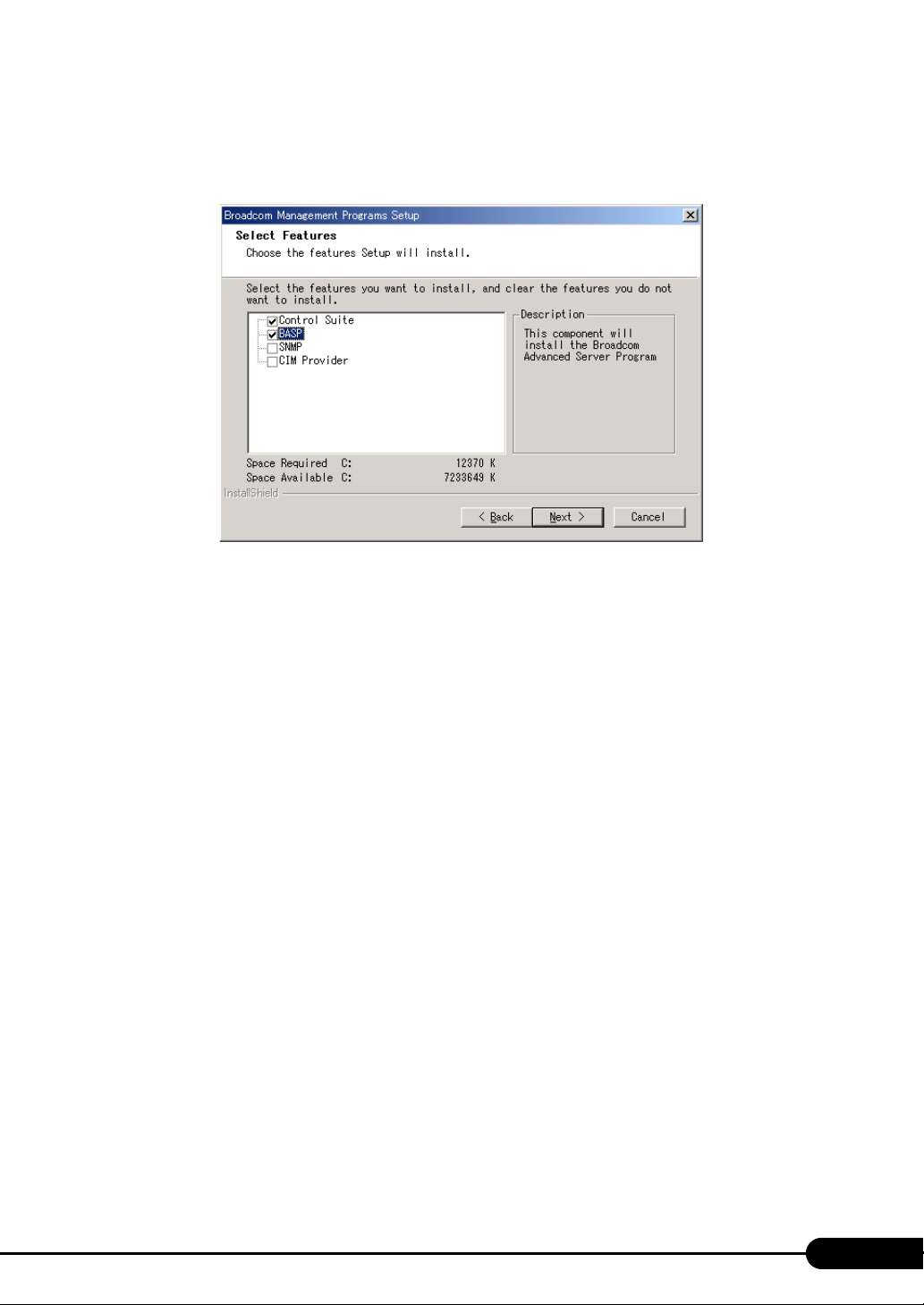
PRIMERGY TX150 S6 User’s Guide
2 Proceed to the installation by following the window instructions.
When the window below appears during the installation procedure, confirm that the checkbox of
[BASP] is checked and click [Next].
97
Page 98
Chapter 4 Operations after OS Installation
4.7 LAN Driver Advanced Setup [Intel® PROSet]
"Intel® PROSet" is a tool for configuring details on the LAN driver. This is used in the
following cases.
• Use the Teaming function between LAN cards or between a LAN card and the
onboard LAN
• Setup a VLAN using a LAN card
• Perform advanced settings of a LAN card
` Use BACS (Jpg.95) to advanced settings of the onboard LAN.
4.7.1 Intel® PROSet Installation
If the tabs such as [Link], [Teaming], and [VLANs] are not added on the property of LAN adapters
which can be selected from the [Device Manager], install Intel
installation procedures:
®
PROSet according to the following
1 Start up the following file contained in the PRIMERGY Startup Disc.
For Windows Server 2003 x64
[CD/DVD drive]:\DRIVERS\LAN\Intel\APPS\PROSETDX\Win64\DxSetup.EXE
For Windows Server 2003
[CD/DVD drive]:\DRIVERS\LAN\Intel\APPS\PROSETDX\Win32\DxSetup.EXE
2 Click [Next].
3 Select [Accept] and click [Next].
4 Select [Driver and Intel(R) PROSet/Advanced Network Service] and click
[Next].
5 Click [Install].
6 Click [Finish].
98
Page 99
PRIMERGY TX150 S6 User’s Guide
4.7.2 Cautions for PG-185x/186x/188x/189x/286x LAN Driver V11.2
Event log
Once a Team is setup, multiple identical logs from the same source that starts with the following log
may be stored in the system log file of the event viewer at system startup.
Source iANSMiniport
ID 11
Typ e Wa rni ng
Description The following adapter link is not connected: (adapter name)
* (adapter name) varies depending on the OS or hardware configuration.
The event logs stated above are ignorable since those will be stored even if the Teaming function is
operating properly.
4.7.3 Teaming Function
Type of teaming
The type of teaming is described below.
z Adapter Fault Tolerance (AFT)
Adapter Fault Tolerance (AFT) is a technology and provides link redundancy by using multiple LAN
ports. When a failure occurs in the link being in use (Primary Link), the communication continues by
switching the process to the standby link (Secondary Link) without interrupting. For AFT, all ports in
the team must be connected to the same switch.
z Adaptive Load Balancing (ALB)
Adaptive Load Balancing (ALB) is a technology that distributes the transmitting and receiving data to
multiple LAN ports to improve the performance in addition to redundancy function of AFT (When
"Receive Load Balancing (RLB)" in advanced setting is set to [Disabled], the reception is done only in
the Primary Link). For ALB, all ports in the team must be connected to the same switch.
z Switch Fault Tolerance (SFT)
Switch Fault Tolerance (SFT) is a redundancy function equal to AFT in configuration when LAN ports
are connected to a separate switch. SFT switches the link to be used between LAN ports and switches
that are connected to the LAN ports when a failure occurs.
However, failures in the links outside of the switches, which are indicated with, or in the figure
below, can not be detected.
99
Page 100
Chapter 4 Operations after OS Installation
→
Switch
Switch
←
↓
PRIMERGY
z Static Link Aggregation
Select this mode when connecting a team to a Cisco FEC/GEC compliant switch or a switch that
supports IEEE802.3ad-Draft Static. Switch settings are also necessary. All ports in the team must be
connected to the same switch.
Notes
When using the Teaming function, note the following points.
• For AFT/ALB/Static link type, up to four LAN ports can be incorporated into one team and two ports
for a SFT type team.
• Once a Team is created, virtual adapters (Team: (Team Name)) will be created in the [Device
Manager] and/or [Network and Dial-up Connections] of the system. Do not disable or delete this
virtual adapter from the [Device Manager] or [Network and Dial-up Connections]. When deleting a
®
virtual adapter, make sure to use "Intel
• When the Teaming function is being used, only the following protocols can be used:
• For AFT/SFT/Static Link: IP, NetBEUI, IPX (NCP), IPX (NetBIOS)
• For ALB type: IP, IPX (NCP)
• When the Teaming function is being used, Windows Load Balancing Service (WLBS) and Network
Load Balancing (NLB) are not available.
• If Static Link function is in use, such switches are only available which is corresponding to link
aggregation.
• When adding/deleting a Static Link member, perform such operation under linked down status.
• The Teaming configuration with the IntelR PROSet Broadcom onboard LAN and the Intel LAN card
is available. Note the following points when configure those settings.
• Make sure to set either one port of the Intel LAN cards as [Set Primary]. For the configuration,
click the [Settings] tab and [Modify Team...], select the LAN card, and click [Set Primary].
PROSet".
100
Only a link down error between a LAN card (onboard LAN) and the switch it connects with, and the
equivalent errors lead to switching of the route. Therefore, if only the switch or LAN card (onboard
LAN) is partially damaged and the route being used is sound at the link level, the route will not be
switched in the team, but the communication with the Team may become an error.
 Loading...