

Page 1

Mainboard Deutsch, English
Short Description
Mainboard D2312
Page 2

Sie haben...
technische Fragen oder Probleme?
Wenden Sie sich bitte an:
• Ihren zuständigen Vertriebspartner oder Ihre Verkaufsstelle
• unsere Hotline über das Kontaktformular unter
www.fujitsu-siemens.com/support/contact/contact.html" oder für
"
Kunden, die ein einzelnes Mainboard gekauft haben: +49(0) 180 3777 005
Aktuelle Informationen zu unseren Produkten, Tipps, Updates usw. finden Sie im
Internet: "
www.fujitsu-siemens.com/mainboards"
Are there...
...any technical problems or other questions you need clarified?
Please co ntact:
• your sales partner o r your sales outlet
• our hotline for customers who have purchased the mainboard as a single
delivery unit: +49(0) 180 3777 005
The latest information and updates (e.g. BIOS update) on our mainboards can be
found on the Internet at: "
www.fujitsu-siemens.com/mainboards"
Page 3

Copyright © Fujitsu Siemens Computers GmbH 2006
Intel, Pentium and Celeron are register ed trademarks of Intel Corporation, USA.
Microsoft, MS, MS-Dos and Windows are registered trademarks of Microsoft Corporation.
PS/2 and O S /2 Warp are registered trademarks of International Business machines, Inc.
All other trademarks referenced are trademarks of their respective owners, whose
protected rights are acknowledged.
All rights, including rights of translation, reproduction by printing, copying or similar
methodas, even of parts are reserved.
Offenders will be liable for damages.
All rights, including rights created by patent grant or registration of a utility model or
design, are reserved. Delivery subject to availability.
Right of technical modification reserved.
Page 4

Dieses Handbuch w urde erstellt von/This manuel was produced by Xerox Global Services
Herausgegeben von/Published by
Fujitsu Siemens Computers GmbH
AG 07/06
Ausgabe/Edition1
Bestell-Nr./Order No.: A26361-D2312-Z110-1-8N19
*A26361-D2312-Z110-1-8N19*
Page 5
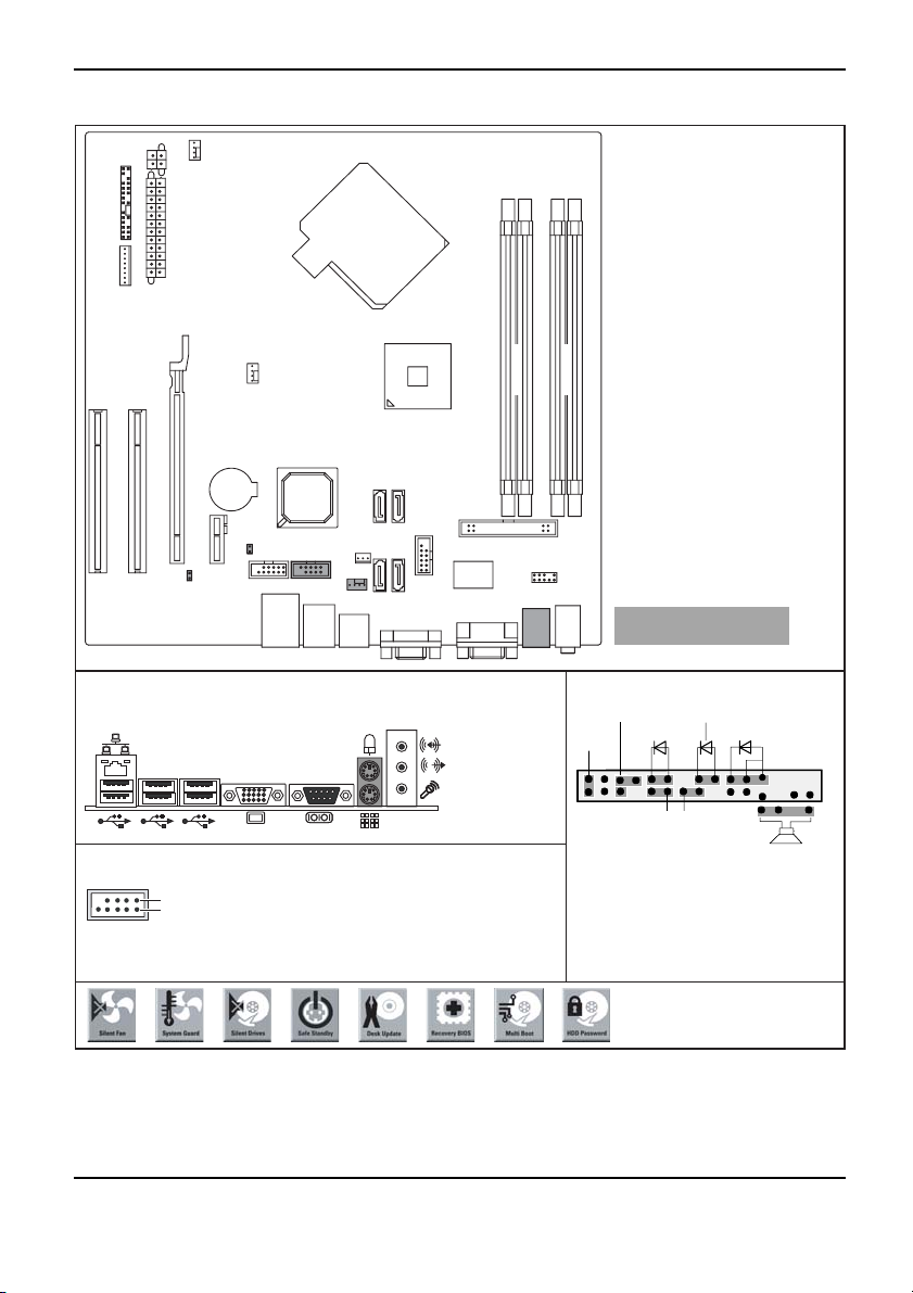
Mainboard D2312 - Internal connecto
Fan 2
Additional power supply
Frontpanel
Power supply
wer
Po
supp ly
cont rol
Fan 1
rs and slots
1
3
Channel A
2
4
Channel B
PCI2
PCI1
PCI e x16
D2312
Battery
PCI e x1
TPM
USB
D2314 TPM
COM2
Intrusion
Fan 3
SATA
21
SATA
43
USB
Floppy disk drive
Front Audio
Optionale Komponenten /
Optional components
External connectors rear Front panel
Power On/Off
Reset
USB dual channel
1
2
1 = VCC C
2 = VCC D
3 = Data negative C
4 = Data negative D
5 = Data positive C
6 = Data positive D
7 = GND
8 = GND
9 = Key
10 = Not connected
1) Both connector positions possible
2) 2pin or 3pin connector possible
Recovery inserted = The system starts
from floppy and allows a BIOS recovery
Password inserted = System- and BIOS
Password are skipped when device is
switched on
1)
Message LED
HD-LED
Power On LED
Recovery Password
Speaker
2)
1
2
A26361-D2312-Z110-1-8N19, Edition 1
Page 6
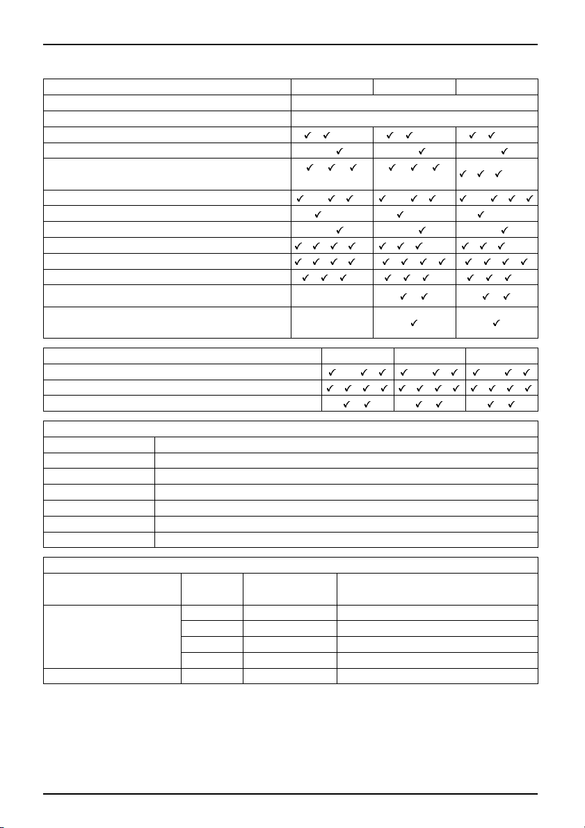
Mainboard D2312
D2312-C
Chipset
Board size
D2312-A D2314
Intel Q965 / ICH8
μBTX
VGA / Audio / 8-channel / S/PDIF / /-/- / /-/- / /-/Buzzer / int. Speaker Support
LAN1Gbit/100Mbit/10Mbit
-/
/ /
(Broadcom)
-/ -/
/ /
(Broadcom)
/ / (Intel)
LAN ASF / Aol / WoL / Boot / iAMT /-/ / /- /-/ / /- /-/ / /
SATA / ATA / R AID /-/- /-/- /-/FireWireTM / USB 2.0 - / -/ -/
FAN monitored FANPS/FAN1/FAN2/FAN3/FAN4 / / / /- / / /-/- / / /-/FAN controlled FANPS/FAN1/FAN2/FAN3/FAN4 / / / /- / / / / / /
TEMP monitored CPU/Inside/System/HDD
SmartCard SystemLock (USB)/ TPM 1.2
Fujitsu Siemens Computers Keybord Power
Button Support
List of spe cial onboard features
Silent Fan/Silent Fan LT/System Guard/Silent Drives
Recovery BIOS/Desk Update/ Multi Boot/Safe Standby
Logo Boot/Intel On Screen Bra ndin g/HDD Passwort
/ / /- / / /- / / /-
-/-
/ /
-
D2312-C
D2312-A D2314
/-/ / /-/ / /-/ /
/ / / / / / / / /
/ / /
Special Features
Silent Fan
Independent temperature related processor and fan supervision and control
System Guard View and adjust Silent Fan
Silent Drives
Recovery BIOS
Desk Update
Multi Boot
HDD Passwort
Noise reduction for optical and hard disk drives
Restores a corrupted BIOS
Simple driver update with DU CD
Comfortable boot from any boot device
Access protection for ATA5/ATAI5 disk drives
Power Supply Requ irem ents - for onboard components (worst case)
Source
Main Power Supply
Voltage
+12V
–12V
+5V
Maximal
variation
+/–5%
+/–10%
+/–5%
Mainboard current (Maximal)
D2312-A/D2312-C/D2314
+3.3V +/–5% 0.5A
Aux. Power Supply
+5V
+/–5%
A26361-D2312-Z110-1-8N19, Edition 1
12 A
0.05 A
6.0 A
2.0 A
Page 7
KurzbeschreibungdesMainboard
Kurzbeschreibung des Mainboa
Hinweise zu den Baugruppen
Beachten Sie bei Baugruppen mit EGB unbedingt F olgendes:
• Sie müssen sich statisch entladen (z. B. durch Berühren eines geerdeten
Gegenstands), bevor Sie mit Baugruppen arbeiten.
• Verwendete Geräte und Werkzeuge müssen frei von statischer Aufladung sein.
• Ziehen Sie den Netzstecker, bevor Sie Baugruppen stecken o der ziehen.
• Fassen Sie die Baugruppen nur am Rand an.
• Berühren Sie keine Anschluss-Stifte oder Leiterbahnen auf der Baugruppe.
Eine Übersicht der Leistungsmerkmale finden Sie im Datenblatt.
Besondere Merkmale
Ihr Mainboard ist in verschiedenen Ausbaustufen erhältlich. Abhängig von der Konfiguration
Ihres Mainboards besitzt oder unterstützt das Mainboard bestimmte Merkmale.
In diesem Handbuch finden Sie die wichtigsten Eigenschaften dieses Mainboards beschrieben.
Weitere Informationen zu Mainboards finden Sie im Handbuch "Basisinformationen Mainboard"
auf der CD "User Documentation" oder "OEM Mainboard" bzw. im Internet.
Anschlüsse und Steckverbi
Die Position der Anschlüsse und Steckverbinder Ihres Mainboards finden
Sie am Anfang des Handbuches.
Die markierten Komponenten und Steckverbinder müssen nicht auf dem Mainboard vorhanden sein.
nder
rd
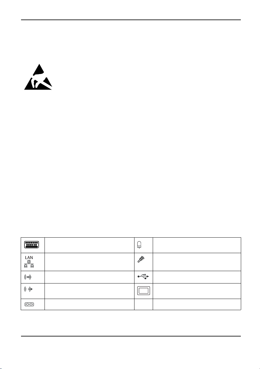
Externe Anschlüsse
Die Position der externen Anschlüsse Ihres Mainboards finden Sie am A nfang des Handbuches.
PS/2-Tastaturanschluss, violett
(optional)
LAN-Anschluss (RJ-45) Mikrofonanschluss, rosa
Audioeingang (Line in),
Audioausgang (Line out), hellgrün VGA, blau
Serielle Schnittstelle,
A26361-D2312-Z110-1-8N19, Ausgabe 1 Deutsch - 1
hellblau
türkis
PS/2-Mausanschluss, grün (optional)
USB – Universal Serial Bu
s, schwarz
Page 8
Kurzbeschreibung des Mainboard
Die externen USB-Anschlüsse auf der Rückseite dürfen zusammen
bis max. 2 A belastet werden.
Grafikcontroller
• Intel GMA 3000
• 256 MByte Video Memory
• Unterstützung von ADD2 Karten (single und dual DVI Adapter Karte)
Auflösung (Farbtiefe bis zu 32 Bi
1024 x 768 (empfohlen / max*) 120 / 200 Hz
1280 x 1024 (empfohlen / max*) 100 / 120 Hz
1600 x 1200 (empfohlen / max*) 85 / 1 20 Hz
1440 x 900 Widescreen TFT (VGA /
1680 x 1050 Widescreen TFT (VGA
1920 x 1200 Widescreen TFT (VGA /
* maximale Bildwiederholrate f
verzerrt ("deteriorated") s
ein, wenn die Maximaleinstellung verwendet wird.
t/Pixel)
DVI)
/DVI)
DVI)
ür die Grafikeinstellung. Die Videoqualität kann
Frequenz
x/x
x/x
x/x
Prozessor ein-/ausbauen (mit Kühlkörper)
Für alle hier beschriebenen Arbeiten muss Ihr System vollständig von der Netzspannung
getrennt sein! Nähere Angaben dazu finden Sie in der Betriebsanleitung Ihres Systems.
Technische Daten
• Intel Pentium 4, Intel Pentium D oder Intel CoreTM2 Duo mit 533/800/1066 MHz
Front Side Bus (max. 95 W) in der Bauform LGA775
• Eine aktuelle Liste der von diesem Mainboard unterstützten Prozessoren finden Sie
im Internet unter: "
www.fujitsu-siemens.com/mainboards".
2 - Deutsch A26361-D2312-Z110-1-8N19, Ausgabe 1
Page 9
Fassen Sie auf keinen F all die Unterseite des Prozessors an. Schon leichte
Verunreinigungen wie Fett von der Haut können die Funktion des Prozessors
beeinträchtigen oder den Prozessor zerstören . Setzen Sie den Prozessor mit
großer Sorgfalt in d en Steckplatz, da die Federkontakte des Steckplatzes sehr
empfindlich sind und nicht verbogen werden dürfen.
Sind ein oder mehrere Federkontakte verbogen, setzen Sie auf keinen Fall
den Prozessor ein, da dieser dadurch beschädigt werden könnte. Wenden
Sie sich bitte direkt an Ihren zuständigen Händler
Vorgehensweise
Der Steckplatz für Prozessor ist zum Schutz der Federkontakte mit einer Schutzkappe
abgedeckt. Im Garantiefall kann das Mainboard nur mit befestigter Schutzkappe
von Fujitsu Siemens Computers zurück genommen werden!
b
KurzbeschreibungdesMainboard
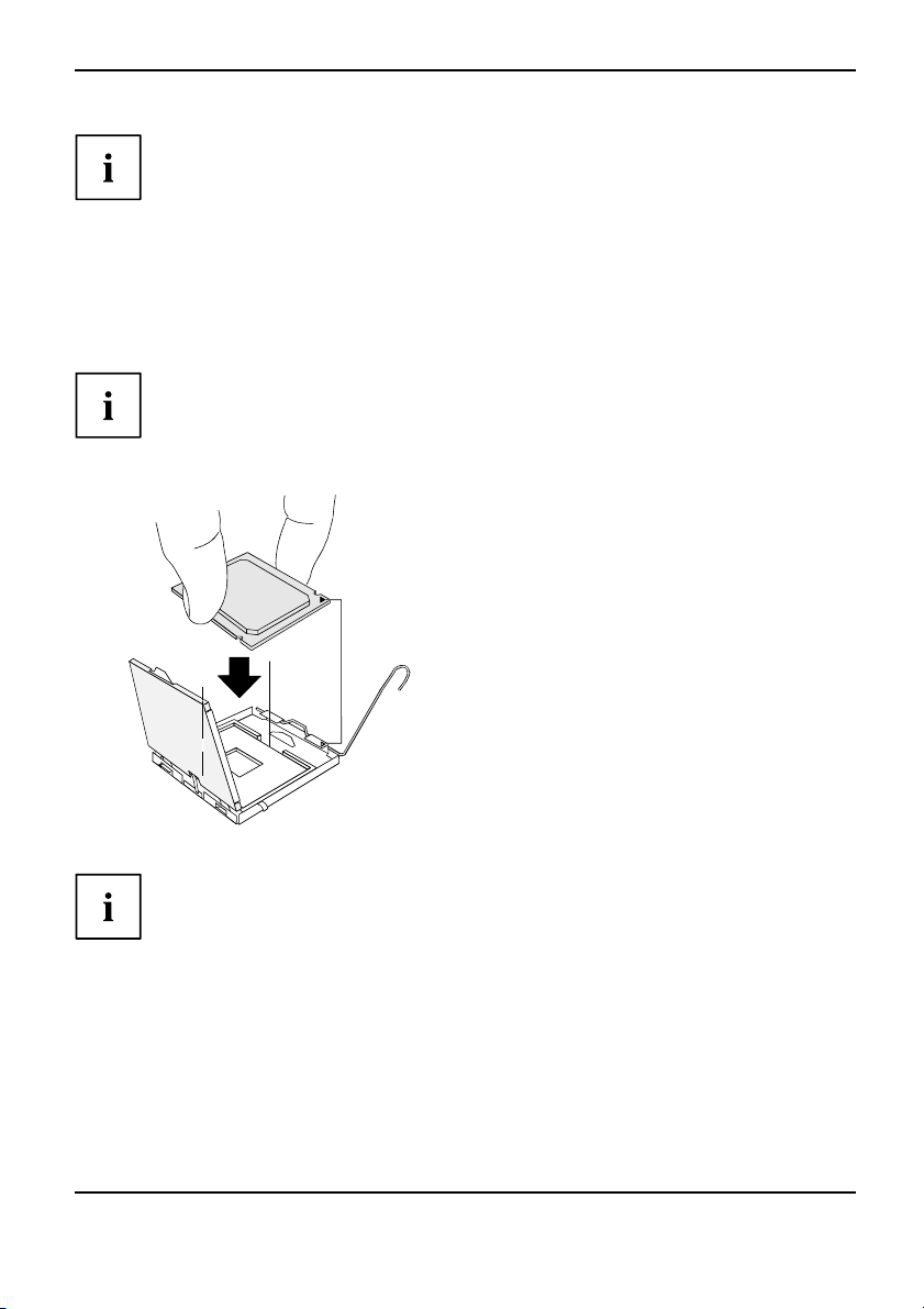
► Entfernen Sie den Kühlkörper.
► Drücken Sie auf den Hebel und
haken Sie ihn aus.
► Klappen Sie die Halterung nach oben.
► Halten Sie den Prozessor mit Daumen
und Zeigefinger und stecken Sie ihn
so in den Steckplatz (b), dass die
Markierung des Prozessors mit der
b
a
Markierung am Steckplatz von der Lage
her übereinstimmt (a).
► Drücken Sie den Hebel nach unten,
bis er wieder einhakt.
► Entfernen Sie die Schutzklappe und
verwahren Sie diese.
Bitte beachten Sie, dass je nach verwendetem Kühlkörper unterschiedliche
Kühlkörperhalterungen auf dem Mainboard benötigt werden.
► Je nach Ausbau-
Kühlkörper mi
► Befestigen Sie den Kühlkörper - je nach Ausführung - mit vier Schrauben
oder stecken Sie ihn in die Befestigungen.
A26361-D2312-Z110-1-8N19, Ausgabe 1 Deutsch - 3
Variante müssen Sie eine Schutzfolie vom Kühlkörp er abziehen oder den
t Wärmeleitpaste bestreichen, bevor Sie ihn aufsetzen.
Page 10
Kurzbeschreibung des Mainboard
Hauptspeicher ein-/ausbauen
Für alle hier beschriebenen Arbeiten muss Ihr System vollständig von der Netzspannung
getrennt sein! Nähere Angaben dazu finden Sie in der Betriebsanleitung Ihres Systems.
Technische Daten
Technologie
Gesamtgröße 128 MBytes bis 8 GByte DDR2
Modulgröße
Eine aktuelle Liste der für dieses Mainboard empfohlenen Speichermodule finden Sie
im Internet unter: "
Es muss mindestens ein Speichermodul eingebaut sein. Speichermodule mit unterschiedlicher
Speicherkapazität können kombiniert werden.
DDR2 533 / 667 / 800 ungepufferte DIMM Module 240-Pin; 1,8 V; 64 Bit, ohne ECC
128, 256, 512, 1024 oder 2048
MByte pro Modul
www.fujitsu-siemens.com/mainboards".
Es dürfen nur ungepufferte 1 ,8 V-Speichermodule ohne ECC verwendet werden.
DDR2-Speichermodule müssen der PC2-4200U- oder PC2-5300U- oder
PC2-6400U-Spezifikation entsprechen.
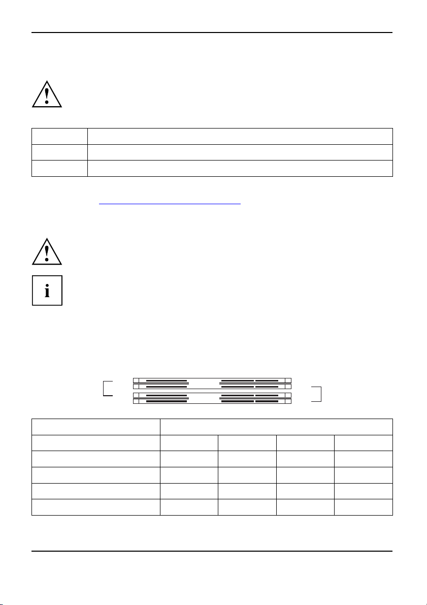
Wenn Sie mehr als ein Speichermodul verwenden, dann achten Sie darauf,
die Speichermodule auf beide Speicherkanäle aufzuteilen. Dadurch nutzen
Sie die Performancevorteile des Dual-Channel-Mode.
Die maximale Systemperformance ist gegeben, wenn in Channel A und
Channel B d ie gleiche Speichergröße verwendet wird.
Um die Bestückung zu erleichtern, sind die Steckplätze (Slots) farbig gekennzeichnet.
Bei einer Speicherkonfiguration von 8 Gbyte kann der sichtbare und benutzbare Haupt-
speicher auf bis zu 7 Gbyte reduziert sein (abhängig von der Konfiguration des Systems).
slot 4
slot 3
Channel B
Channel A
slot 2
slot 1
Anzahl der gesteckten Speichermodule
Zu verwendender Steckplatz 1 2 3 4
Channel A, Slot 1
Channel A, Slot 3
Channel B, Slot 2
Channel B, Slot 4
xxxx
xx
xxx
x
4 - Deutsch A26361-D2312-Z110-1-8N19, Ausgabe 1
Page 11
Kurzbeschreibungdes Mainboard
Der Ein-/Ausbau ist im Handbuch "Basisinformationen Mainboard" beschrieben.
PCI-Bus-Interrupts - Auswahl des richtigen PCI-Steckplatzes
Umfangreiche Informationen zu diesem Abschnitt finden Sie im Handbuch
"Basisinformationen Mainboard".
Um optimale Stabilität, Perf ormance und Kompatibilität zu erreichen, vermeiden
Sie die mehrfache Nutzung von ISA IRQs oder PCI IRQ Lines (IRQ Sharing).
Sollte IRQ Sharing nicht zu umgehen sein, so müssen alle beteiligten Geräte
und deren Treiber IRQ Sharing unterstützen.
Welche ISA IRQs den PCI IRQ Lines zugeordnet werden, wird normalerweise automatisch
vom BIOS festgelegt (siehe Beschreibung "
Monofunktionale Erweiterungskarten
PCI-/PCI-Express-Erweiterungskarten benötigen maximal einen Interrupt, der als
PCI-Interrupt INT A bezeichnet wird. Erweiterungskarten, die keinen Interrupt benötigen,
können in einen beliebigen Steckplatz eingebaut werden.
Multifunktionale Erweiterungskarten oder Erweiterungskarten mit integrierter PCI-PCI Brigde
Diese Erweiterungskarten benötigen bis zu vier PCI-Interrupts: INT A, INT B, INT
C, INT D. Wie viele und welche dieser Interrupts verwendet werden, entnehmen
Sie der mitgelieferten Dokumentation der Karte.
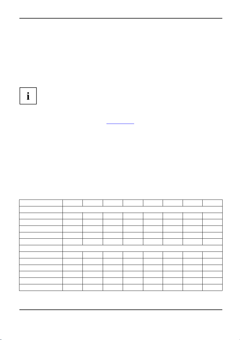
Die Zuordnung der PCI-Interrupts zu den IRQ Lines finden Sie in der folgenden Tabelle:
BIOS-Setup").
On board con troller
PCI INT LINE
1(A) 2(B) 3(C) 4(D) 5(E) 6(F) 7(G) 8(H)
UHCI USB 1.1
Dev 1A Fn 0 1
Dev 1A Fn 1 2
Dev1DFn03
Dev 1D Fn 1 4
Dev 1A Fn 2 5
----
nd
-
rd
-------
th
------
th
-----
x
------
x
---
x
x
x
--
-
th
EHCI USB 2.0
Dev 1A Fn 7
Dev 1D Fn 7
SATA #1
SATA #2
SMBus
Intel LAN
-
x
-------
---
-
x
---
--
-----x
x
----
------
x
x
-----
----
A26361-D2312-Z110-1-8N19, Ausgabe 1 Deutsch - 5
Page 12
Kurzbeschreibung des Mainboard
PCI INT LINE
HD Audio
Broadcom LAN DABC
Onboard Graphik
Mechanical Slot
PCI INT LINE
PCIe x16 ABCD
PCIe x1
PCI 1
PCI 2
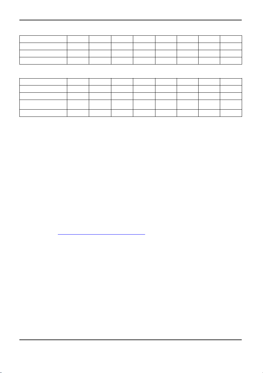
Verwenden Sie zuerst PCI-/PCI-Express-Steckplätze, die über eine einzige PCI IRQ Line
verfügen (kein IRQ Sharing). Wenn Sie einen an deren PCI-/PCI-Express-Steckplatz mit IRQ
Sharing benutzen müssen, überprüfen Sie, ob die Erweiterungskarte IRQ Sharing mit den
anderen Geräten auf dieser PCI IRQ Line einwandfrei unterstützt. Auch die Treiber aller Karten
und Komponenten an dieser PCI IRQ Line müssen IRQ Sharing unterstützen.
1(A) 2(B) 3(C) 4(D) 5(E) 6(F) 7(G) 8(H)
----
x
1(A) 2(B) 3(C) 4(D) 5(E) 6(F) 7(G) 8(H)
------
--
--
-- -----
DC
CD
x
----
----
-
-
---
x
BA
AB
BIOS-Update
Wann sollte ein BIOS-Update durchgeführt werden?
Fujitsu Siemens Computers stellt neue BIOS-Versionen zur Verfügung, um die Kompatibilität
zu neuen Betriebssystemen, zu neuer Software oder zu neuer Hardware zu ge währleist en.
Außerdem können neue B IO S-F unktio nen integriert werden.
Ein BIOS-Update sollte auch immer dann durchgeführt werden, wenn ein Problem besteht,
das sich durch neue Treiber oder neue Software nicht beheben lässt.
-
-
-
Wo gibt es BIOS-Updates?
Im Internet unter "
www.fujitsu-siemens.com/mainboards" finden Sie die BIOS-Upda tes.
BIOS-Update unter DOS mit startfähiger BIOS-Update-Diskette
- Kurzbeschreibun
► Laden Sie die Update-Datei von unserer Internet-Seite auf Ihren PC.
► Legen Sie eine leer
► Führen Sie die Update-Datei aus (z. B. 2461103.EXE).
Es wird eine startfä
► Starten Sie d en PC neu.
► Folgen Sie den Bildsc
6 - Deutsch A26361-D2312-Z110-1-8N19, Ausgabe 1
g
e Diskette (1,44 MByte) ein.
hige Update-Diskette erstellt. Lassen Sie diese Diskette im Laufwerk.
hirmanweisungen.
Page 13
Kurzbeschreibungdes Mainboard
Detaillierte Informationen zum BIOS-Update unter DOS finden Sie im Handbuch
zum "BIOS-Setup" (CD "Drivers & Utilities").
BIOS-Update unter Windows mit d
Ein BIOS-Update kann mit dem Utility DeskFlash auch direkt unter Windows durchgeführt werden.
DeskFlash befi ndet sich auf der CD "Drivers & Utilities" (unter DeskUpdate).
em Utility DeskFlash
A26361-D2312-Z110-1-8N19, Ausgabe 1 Deutsch - 7
Page 14

Kurzbeschreibung des Mainboard
8 - Deutsch A26361-D2312-Z110-1-8N19, Ausgabe 1
Page 15
Brief description of the mainboard
Brief description of the mainb
Information about the boards
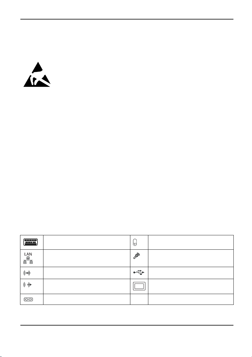
Be sure to observe the following for boards with ESD:
• You must always discharge static build up (e.g. by touching a grounded object)
before working.
• The equipment and tools you use must be free o f static charges.
• Remove the power plug from the mains supply before inserting or removing
boards containing ESDs.
• Always hold boards with ESDs by their edges.
• Never touch pins or conductors on boards fitted with ESDs.
An overview of the features is provided in the data sheet.
Special features
Your mainboard is available in different configuration levels. Depending on the configuration
of your mainboard, it is e quipped with or supports special features.
This manual describes the most important properties of this mainboard.
Additional information on mainboards is contained in the "Basic information on mainboard" manual,
on the "User Documentation" or "OEM Mainboard" CDs, or on the Internet.
oard
Interfaces and connectors
The location of the interfaces and connectors of your mainboa rd is specified
at the beginning of the manual.
The components and connectors marked are not necessarily present on the mainboard.
External ports
The location of the external connections of your mainboard is specified at the beginning of the manual.
PS/2 keyboard port, purpl
LAN port (RJ-45)
Audio input (Line in), light blue USB – Universal Serial Bus, black
Audio output (Line out), light green VGA, blue
Serial interface, turquoise
A26361-D2312-Z110-1-8N19, Edition 1 English - 1
e (optional)
PS/2 mouse port, green (op
Microphone port, pink
tional)
Page 16
Brief description of the m ainboard
The external USB ports on the back may be loaded with a maximum of 2 A between them.
Graphics controller
• Intel GMA 3000
• 256 Mbyte video memory
• Support of ADD2 cards (single and dual DVI adapter card)
Resolution (colour depth up to 3
1024 x 768 (recommended / max*) 120 / 200 Hz
1280 x 1024 (recommended / max*) 100 / 120 Hz
1600 x 1200 (recommended / max*
1440 x 900 Widescreen TFT (VGA /
1680 x 1050 Widescreen TFT (VGA
1920 x 1200 Widescreen TFT (VGA /
* maximum video rate for graphic
deteriorate if the maximum co
2 bits/pixel)
)
DVI)
/DVI)
DVI)
sconfiguration. The video quality may
nfiguration is used.
Frequency
85 / 120 Hz
x/x
x/x
x/x
Installing/removing processor (with heat sink)
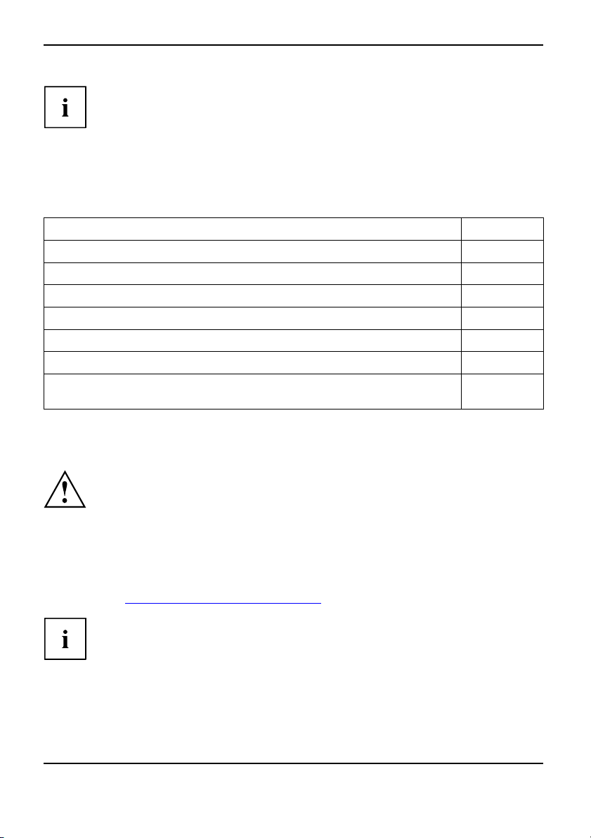
Disconnect the system from the mains voltage before performing any of the tasks
described below. Details are contained in your systems’ operating manual.
Technical data
• Intel Pentium 4, Intel Pentium D or Intel CoreTM2 Duo with 533/800/1066 MHz
front side bus (max. 95 W) in the LGA775 design
• A current list of the processors supported by this mainboard is a vailable on the
Internet at: "
www.fujitsu-siemens.com/mainboards".
Never touch the underside of the processor. Even minor soiling such as grease
from the skin can impair the processor’s operation or destroy the processor.
Place the processor in the socket with extreme care, as the spring contacts
of the socket are very delicate and must not be bent.
If one or more spring contacts are bent, do not insert the processor as it may be
damaged by doing so. Please contact the responsible vendor.
2 - English A26361-D2312-Z110-1-8N19, Edition 1
Page 17
Procedure
The processor socket ist covered with a protective cap to protect the spring
contacts In a warranty case the mainboard can only be taken back by Fujitsu
Siemens Computers with the protective cap secured!
Please note that, depending on the heat sink used, different heat sink
mounts are required on the mainboard.
Brief description of the mainboard
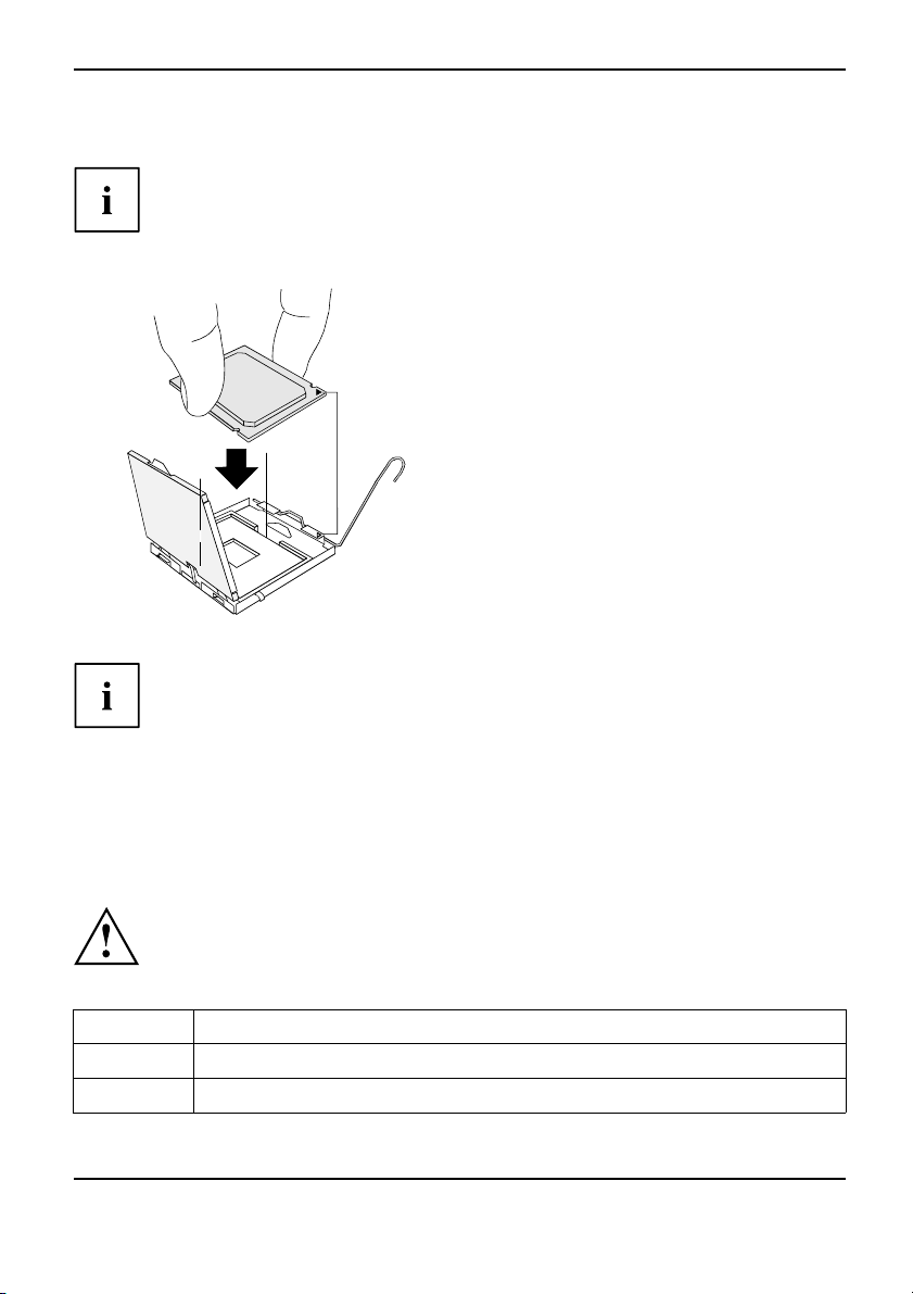
► Remove the heat sink.
► Press down on the lever and unh
► Fold up the frame.
► Hold the processor between you
and index finger and insert it in
(b) so that the marking of the p
alignedwiththemarkingonth
b
b
a
► Press the lever downward until it is
hooked in again.
► Remove the protective cap an
ook it.
r thumb
to the socket
rocessor is
e socket (a).
d keep it.
► Depending on the c
or coat the heat s
► Secure t he heat sink - depending on the model - with four screws or push it into the m ounts.
onfiguration variant, you must pull a protective foil off the heat sink
ink with heat conducting paste before fitting it.
Installing/removing main memory
Disconnect the
tasks describe
Technical data
Technology
Total Size 128 Mbytes to 8 Gbytes DDR2
Module size 128, 256, 512, 1024 or 2048 Mbytes per module
A26361-D2312-Z110-1-8N19, Edition 1 English - 3
DDR2 533 / 667 / 800 unbuffered DIMM modules 240-Pin; 1.8 V; 64 Bit, no ECC
system completely from the mains voltage before performing any of the
d below. Details are contained in your systems’ operating manual.
Page 18
Brief description of the m ainboard
A current list of the memory modules recommended for this mainboard is available on
the Internet at: "
www.fujitsu-siemens.com/mainboards".
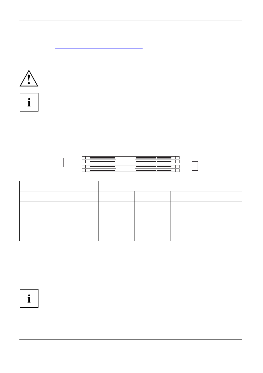
At least one memory module must be installed. Memory modules with different
memory capacities can be combined.
You may use only unbuffered 1.8 V memory modules without ECC.
DDR2-memory modules must meet the PC2-4200U, PC2-5300U or
PC2-6400U specification.
If you use more than one memory module, make sure to distribute the
memory modules over both memory channels. By doing this you use the
performance advantages of t he dual-channel mode.
The maximum system performance is g iven when the same memory size
is used in Channel A and Channel B.
To simplify equipping, the slots are colour coded.
With a memory configuration of 8 Gbytes the visible and usable main memory can
be reduced down to 7 Gbytes (depending on the system configuration).
slot 4
slot 3
Channel B
Channel A
slot 2
slot 1
Number of inserted memory modules
Slot to be used 1 2 3 4
Channel A, slot 1
Channel A, slot 3
Channel B, slot 2
Channel B, slot 4
xxxx
xx
xxx
x
The installation/removal is described in the "Basic information on mainboard" manual.
PCI bus interrupts - Selecting correct PCI slot
Extensive information on this section is contained in t he "Basic information on mainboard" manual.
To achieve optimum stability, performance and compatibility, avoid the multiple use
of ISA IRQs or PCI IRQ Lines (IRQ sharing). Should IRQ sharing be unavoidable,
then all involved devices and their drivers must support IRQ sharing.
4 - English A26361-D2312-Z110-1-8N19, Edition 1
Page 19
Brief description of the mainboard
Which ISA IRQs are assigned to the PCI IRQ Lines is normally automatically specified
by the BIOS (see "
BIOS Setup" description).
Monofunctional expansion cards
PCI/PCI Express expansion cards require a maximum of one interrupt, which is called the PCI
interrupt INT A. Expansion cards that do not require an interrupt can be installed i n any desired slot.
Multifunctional expansion cards or expansion cards with integrated PCI-PCI bridge
These expansion cards require up to four PCI interrupts: INT A, INT B, INT C, INT D . How many and
which of these interrupts are used is specified in the documentation provided with the card.
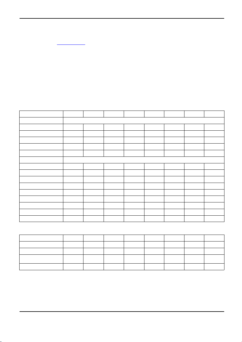
The assignment of the PCI interrupts to the IRQ Lines is shown in the following table:
On board con troller
PCI INT LINE
1(A) 2(B) 3(C) 4(D) 5(E) 6(F) 7(G) 8(H)
UHCI USB 1.1
Dev 1A Fn 0 1
Dev 1A Fn 1 2
Dev1DFn03
Dev 1D Fn 1 4
Dev 1A Fn 2 5
----
nd
-
rd
-------
th
------
th
-----
x
------
x
---
x
x
x
--
-
th
EHCI USB 2.0
Dev 1A Fn 7
Dev 1D Fn 7
SATA #1
SATA #2
SMBus
Intel LAN
HD Audio
-
-------
---
-
---
--
----
x
x
Broadcom LAN DAB
Onboard Graphik
x
-- -----
-----x
x
----
------
x
x
-----
C
----
x
---
----
Mechanical slot
PCI INT LINE
PCIe x16 ABCD
PCIe x1
PCI 1
PCI 2
1(A) 2(B) 3(C) 4(D) 5(E) 6(F) 7(G) 8(H)
----
------
--
--
DC
CD
-
-
BA
AB
x
-
-
-
First use PCI/PCI Express slots that have a single PCI IRQ Line (no IR Q sharing). If you
must use another PCI/PCI Express slot with IRQ sharing, check whether the e xpan sion card
properly supports IRQ sharing with the other devices on this PCI IRQ Line. The drivers of all
cards and components on this PCI IRQ Line must also support IRQ sharing.
A26361-D2312-Z110-1-8N19, Edition 1 English - 5
Page 20
Brief description of the m ainboard
BIOS update
When should a BIOS u pdate be carried out?
Fujitsu Siemens Computers makes new BIOS versions available to ensure compatibility with new operating systems, new software or new hardware. In addition, new BIOS functions can also be integrated.
A BIOS update should always also be carried out when a problem exists that cannot
be solved with new drivers or new software.
Where can I obtain BIOS updates?
BIOS updates are available on the Internet at "
www.fujitsu-siemens.com/mainboards".
BIOS update under DOS with boo
table BIOS update
floppy disk - brief description
► Download the update file from our website onto your PC.
► Insert a blank floppy disk (1.44 Mbyte).
► Run the update file (e.g. 2461103.EXE).
A bootable update floppy disk is created. Leave this floppy disk in t he drive.
► Restart the PC.
► Follow the instructions on screen.
Detailed information on the BIOS update under DOS is provided in the
"BIOS Setup" manual (CD "Drivers & Utilities").
BIOS update under Windows with DeskFlash utility
A BIOS update can also be carried out directly under Windows with the DeskFlash utility.
DeskFlash is contained on the "Drivers & Utilities" CD (under DeskUpdate).
6 - English A26361-D2312-Z110-1-8N19, Edition 1
 Loading...