

Page 1

answers
Mainboard D1607
Deutsch / English / Français
2
Technisches Handbuch / Technical Manual
Page 2

Sie haben ...
... technische Fragen oder Probleme?
Wenden Sie sich bitte an:
• Ihren zuständigen Vertriebspartner
• Ihre Verkaufsstelle
Aktuelle Informationen und Updates (z. B. BIOS-Update) zu unseren Mainboards finden Sie im
Internet: http://www.fujitsu-siemens.com/mainboards
Are there ...
... any technical problems or other questions you need clarified?
Please contact:
• your sales partner
• your sales outlet
The latest information and updates (e.g. BIOS update) on our mainboards can be found on the
Internet under: http://www.fujitsu-siemens.com/mainboards
Vous avez ...
...des questions techniques ou des problèmes ?
Veuillez contacter :
• Votre partenaire Commercial
• Votre point de Vente
Les dernières informations ainsi que les updates (p.ex. BIOS-Update) par rapport à nos cartes
mères sont à votre disposition sur Internet : http://www.fujitsu-siemens.com/mainboards
Page 3

Page 4

Dieses Handbuch wurde auf Recycling-Papier gedruckt.
This manual has been printed on recycled paper.
Ce manuel est imprimé sur du papier recyclé.
Este manual ha sido impreso sobre papel reciclado.
Questo manuale è stato stampato su carta da riciclaggio.
Denna handbok är tryckt på recyclingpapper.
Dit handboek werd op recycling-papier gedrukt.
Herausgegeben von/Published by
Fujitsu Siemens Computers GmbH
Bestell-Nr./Order No.:
Printed in the Federal Republic of Germany
AG 0803 08/03
A26361-D1607-Z120-1-6319
A26361-D1607-Z120-1-6319
Page 5
Deutsch
English
Mainboard D1607
Technisches Handbuch
Technical Manual
Français
Ausgabe August 2003
August 2003 edition
Page 6

AMD, AMD Arrow logo, AMD Athlon, AMD Opteron und Kombinationen sowie 3DNow! sind
Warenzeichen von Advanced Micro Devices, Inc.
HyperTransport ist ein lizensiertes Warenzeichen von HyperTransport Technology
Consortium.
Microsoft, MS, MS-DOS und Windows sind eingetragene Warenzeichen der Microsoft
Corporation.
PS/2 und OS/2 Warp sind eingetragene Warenzeichen von International Business Machines,
Inc.
Alle weiteren genannten Warenzeichen sind Warenzeichen oder eingetragene Warenzeichen
der jeweiligen Inhaber und werden als geschützt anerkannt.
Copyright Fujitsu Siemens Computers GmbH 2003
Alle Rechte vorbehalten, insbesondere (auch auszugsweise) die der Übersetzung, des
Nachdrucks, der Wiedergabe durch Kopieren oder ähnliche Verfahren.
Zuwiderhandlungen verpflichten zu Schadenersatz.
Alle Rechte vorbehalten, insbesondere für den Fall der Patenterteilung oder GM-Eintragung.
Liefermöglichkeiten und technische Änderungen vorbehalten.
Dieses Handbuch wurde erstellt von
cognitas. Gesellschaft für Technik-Dokumentation mbH
www.cognitas.de
AMD, AMD Arrow logo, AMD Athlon, AMD Opteron and combinations thereof, and 3DNow!
are trademarks of Advanced Micro Devices, Inc.
HyperTransport is a licensed trademark of the HyperTransport Technology Consortium.
Microsoft, MS, MS-DOS and Windows are registered trademarks of Microsoft Corporation.
PS/2 and OS/2 Warp are registered trademarks of International Business Machines, Inc.
All other trademarks referenced are trademarks or registered trademarks of their respective
owners, whose protected rights are acknowledged.
All rights, including rights of translation, reproduction by printing, copying or similar methods,
even of parts are reserved.
Offenders will be liable for damages.
All rights, including rights created by patent grant or registration of a utility model or design,
are reserved. Delivery subject to availability.
Right of technical modification reserved.
This manual was produced by
cognitas. Gesellschaft für Technik-Dokumentation mbH
www.cognitas.de
Page 7

Page 8
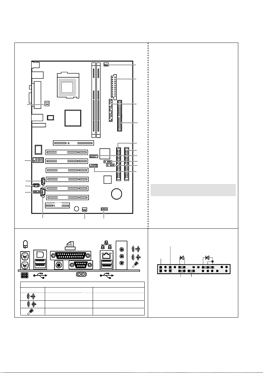
Übersicht/Overview Mainboard D1607
Interne Anschlüsse und Steckplätze / Internal
connectors and slots
DIMM 2
DIMM 1
CPU
AMD
Athlon 64
18
AGP
PCI 1
17
16
15
14
PCI 2
PCI 3
PCI 4
PCI 5
PCI 6
CNR
1 = Lüfter 1 / Fan 1
2 = Stromversorgung / Power supply
3 = Bedienfeld / Front panel
4 = Diskettenlaufwerk / Floppy disk drive
1
5 = IDE-Laufwerke 3/4 / IDE-drives 3/4
6 = IDE-Laufwerke 1/2 / IDE-drives 1/2
2
7 = USB E/G
8 = Serial ATA 1
9 = Serial ATA 2
10 = USB F/H
3
11 = SMB (für Temperatursensor /
Temperature sensor)
12 = Lüfter 2 / Fan 2
4
13 = AUX-Audio in
14 = Audio-Bedienfeld / Audio front panel
15 = CD-Audio in
5
16 = S/PDIF IN-Anschluss / S/PDIF IN
10
6
7
8
9
connector
17 = FireWire-Anschluss (1394) / FireWire
connector (1394)
18 = Zusätzliche Stromversorgung /
Processor power supply
Optionale Komponenten / Optional
components
13
12
11
Externe Anschlüsse / External connectors
1394
S/PDIF
Umschaltbar durch Treiber /
Standard 6-channel
Line In (blau/blue)
Line Out (grün/green)
Mic In (rot/red)
Switchable via driver
Rear
Front
Center / Low
Bedienfeld / Front panel
Power On/Off
HD-LED
1)
Reset
BIOS Recovery Password skip
1) Cable is not included in the delivery scope.
2) 2-pin or 3-pin connector possible
1)
Power On
1) 2)
LED
1
2
Page 9

Contents
Mainboard D1607.............................................................................................................................1
Notational conventions...............................................................................................................1
Important notes .................................................................................................................................2
Information about boards ...........................................................................................................2
List of features...................................................................................................................................3
Special features.........................................................................................................................5
Brief instructions on installing mainboard...........................................................................................7
Prior to installation.....................................................................................................................7
Interfaces and connectors ..............................................................................................................9
External ports ....................................................................................................................................9
LAN connector...........................................................................................................................9
Audio ports and audio configuration......................................................................................... 10
Internal ports and connectors ..........................................................................................................12
Hard disk connection ...............................................................................................................12
Audio front panel......................................................................................................................12
Pin assignment of internal ports.......................................................................................................13
Settings with switches and jumpers ............................................................................................19
Add-on modules / Upgrading........................................................................................................21
Replacing processor........................................................................................................................21
Removing and installing processors ........................................................................................21
Upgrading main memory .................................................................................................................23
Upgrading AGP screen controllers...................................................................................................24
Adding PCI cards.............................................................................................................................24
PCI bus interrupts - Selecting correct PCI slot.........................................................................25
Replacing the lithium battery....................................................................................................26
BIOS update....................................................................................................................................27
BIOS Recovery - Recovering System BIOS.....................................................................................27
Drivers.............................................................................................................................................28
Annex .............................................................................................................................................29
Electrical Properties.........................................................................................................................29
APM and ACPI system status, energy-saving modes ......................................................................30
Mainboard Revision and BIOS Version............................................................................................ 31
Error messages .............................................................................................................................32
Glossary..........................................................................................................................................35
A26361-D1607-Z120-1-6319 English
Page 10

Page 11
Mainboard D1607
Your mainboard is available in different configuration levels. Depending on the configuration chosen,
some of the hardware components described may not be available on your mainboard.
Additional information
Information on the BIOS Setup and additional descriptions of the drivers are contained:
• in the readme files on your hard disk
• on the driver floppy disks included
• on the CD "Drivers & Utilities Collection" or "Drivers & Utilities" or "ServerStart".
The programme Acrobat Reader must be installed to be able to open the manuals. You
will find the programme on the CD-ROM directory: utls/acrobat.
i
For more details please read the according readme.txt files.
Notational conventions
The meanings of the symbols and fonts used in this manual are as follows:
indicates information which is important for your health or for preventing physical
damage.
!
indicates additional information which is required to use the system properly.
i
Ê Text which follows this symbol describes activities that must be performed in the order shown.
↵ This symbol indicates that you must press the Enter key.
Text in this typeface indicates screen outputs.
Text in this bold typeface indicates the entries you make via the keyboard.
Text in italics indicates commands or menu items.
"Quotation marks" indicate names of chapters or terms.
A26361-D1607-Z120-1-6319 English - 1
Page 12
Important notes
Important notes
With the mainboard installed you must open the system to access the mainboard. How to dismantle
and reassemble the system is described in the operating manual accompanying the system.
Connecting cables for peripherals must be adequately insulated to avoid interference.
Observe the safety notes in the operating manual of your system.
!
Incorrect replacement of the lithium battery may lead to a risk of explosion. It is therefore
essential to observe the instructions in the "Add-on modules / Upgrading" - "Replacing
the lithium battery" section.
Components can become very hot during operation. Ensure you do not touch
components when making extensions to the mainboard. There is a danger of burns!
The shipped version of this board complies with the requirements of the EEC directive
89/336/EEC "Electromagnetic compatibility".
Compliance was tested in a typical PC configuration.
When installing the board, refer to the specific installation information in the manual for
the receiving device.
The warranty is invalidated if the system is damaged during the installation or
replacement of expansions. Information on which expansions you can use is available
i
from your sales outlet or the customer service centre.
Information about boards
To prevent damage to the mainboard, the components and conductors on it, please take great care
when you insert or remove boards. Take great care to ensure that extension boards are slotted in
straight, without damaging components or conductors on the mainboard, or any other components,
for example EMI spring contacts.
Remove the plug from the mains outlet so that system and mainboard are totally disconnected from
the mains voltage.
Be careful with the locking mechanisms (catches, centring pins etc.) when you replace the
mainboard or components on it, for example memory modules or processors.
Never use sharp objects (screwdrivers) for leverage.
Boards with electrostatic sensitive devices (ESD) are identifiable by the label shown.
When you handle boards fitted with ESDs, you must, under all circumstances,
observe the following:
• You must always discharge static build up (e.g. by touching a grounded object)
before working.
• The equipment and tools you use must be free of static charges.
• Remove the power plug from the mains supply before inserting or removing
boards containing ESDs.
• Always hold boards with ESDs by their edges.
• Never touch pins or conductors on boards fitted with ESDs.
2 - English A26361-D1607-Z120-1-6319
Page 13
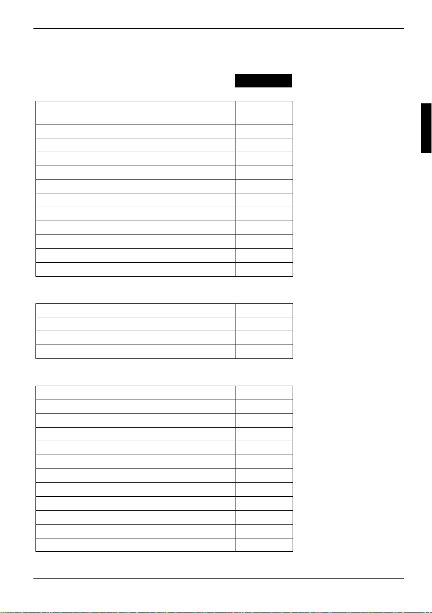
List of features
D1607-G
Features
Chipset
Board Size ATX
VGA Audio / 6-channel / S/PDIF 5.1 ! / ! / !
Buzzer / int. Speaker Support ! / LAN Gbit / 100 Mbit / 10 Mbit - / ! / !
LAN ASF / AOL / WOL / Boot - / - / ! / !
Serial ATA / ATA / RAID ! / ! / !
FireWire™ / USB 2.0 ! / !
FAN monitored PSU**/CPU/AUX1/AUX2 - / ! / ! / FAN controlled PSU**/CPU/AUX1/AUX2 - / ! / ! / TEMP monitored CPU/ONB1/ONB2/OFFB ! / ! / - / !
Special Features
Silent Fan / System Guard / Silent Drives ! / ! / !
Recovery BIOS / Desk Update / Multi Boot ! / ! / !
HDD Password / USB Security - / !
Logo Boot !
VIA K8T800 /
VT8237
List of features
Internal ports
DIMM slots (DDR400 SDRAM, PC3200) 2
AGP Slot (2/4/8x, 32 bit, 66 MHz, 1.5 V) 1
PCI slots (32 bit, 33 MHz, 5 V and 3.3 V) 6
CNR Slot (Type A, AC‘97 only) 1
S-ATA (150) / ATA (133) / Floppy 2 / 2 / 1
S/PDIF * (5.1 digital Audio) OUT / IN - / 1
CD / AUX audio input 1 / 1
Front panel Audio (9-pin for headphone, microphone) 1
FireWire™ * (9-Pin, Intel Standard) 1
USB * (2.0, ~480 MB/s) 4
Serial Ports* (FIFO, 16550 compatible) Fan PSU** / CPU / AUX1 / AUX2 - / 1 / 1 / -
A26361-D1607-Z120-1-6319 English - 3
Page 14
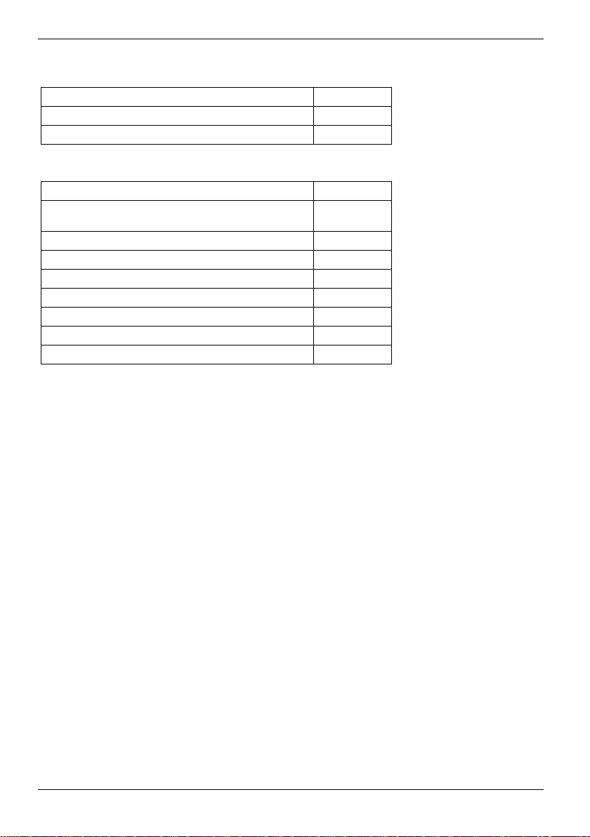
List of features
Internal ports (continued)
SMBus * (Case Temperature) 1
Cover monitoring* (Casing open)Power supply ATX/ATX 12V/AGP Pro 1 / 1 / -
External ports
VGA Audio Mic. In/Line in/Line out (or configurable with
driver)
S/PDIF (5.1 digital audio, cinch) OUT / IN 1 / LAN (RJ-45) 1
PS/2 mouse/keyboard 1 / 1
FireWire™ (6-Pin, IEEE 1394) 1
USB (2.0, ~480 MB/s) 4
Serial Ports (RS232, FIFO, 16550 compatible) 1
Parallel Ports (EPP/ECP) 1
* for use with internal devices or optional Front or Rear panel
** not supported by standard power supplies
1 / 1 / 1
4 - English A26361-D1607-Z120-1-6319
Page 15
List of features
Special features
Your mainboard is available in different configuration levels. Depending on the configuration, your
mainboard is equipped with or supports the features described in the following.
Silent Fan
A micro controller developed by Fujitsu Siemens Computers monitors and controls the
fans in the PC and thus prevents any unnecessary noise annoyance. Should the
processor become in spite of full turning ventilator too hot, then the processor clock
rate will automatically be reduced so that the system continues to run stably. The
microcontroller operates independently of the operating system and the processor.
Therefore the micro controller protects your PC reliably against overheating and loss
of data or even damage of the processor.
In addition, the microcontroller offers monitoring of, for example, system voltages
(12 V, 5 V, CMOS), opening of the case and a watchdog function.
SystemGuard
With SystemGuard the function of the onboard Silent Fan Controller is displayed.
SystemGuard indicates temperature, rotational speed of the fan and voltages, which
are measured by the Silent Fan Controller. Moreover the software offers various
setting options to optimise the noise level. SystemGuard is a freeware-tool, which is
available on the internet.
Silent Drives
After the fans, hard disks and optical drives (CD-ROM, CD-RW, DVD etc.) are one of
the greatest sources of noise in a PC and can be switched into a quieter mode via the
BIOS. Together with the fan control via Silent Fan on our Premium mainboards, this
results in an extremely quiet PC.
Recovery BIOS
Recovery BIOS permits the recovery of the BIOS as often as desired following
destruction of the BIOS content due to an incomplete flash process.
DeskUpdate
DeskUpdate enables simple, automatic driver installation. The function is available
both on the OEM CD "Drivers & Utilities" and on the Internet.
A26361-D1607-Z120-1-6319 English - 5
Page 16
List of features
Multi Boot
The BIOS of the Fujitsu Siemens Computers mainboards enables booting from all
types mass storage devices. In addition to IDE hard disks, this also includes optical
drives, such as CD-ROM, DVD and external drives that can be connected to USB or
FireWire.
USB Security
USB Security is a BIOS function that offers protection against unauthorised access
regardless of the operating system used. After the feature has been activated with a
Fujitsu Siemens Memorybird, the system can only be started when this Memorybird is
connected to one of the available USB ports.
6 - English A26361-D1607-Z120-1-6319
Page 17
Brief instructions on installing mainboard
Brief instructions on installing mainboard
If you have purchased a separate mainboard, you can install it in your system in accordance with
the following brief instructions.
The activities described here assume a basic knowledge of PCs and cannot be carried out by a
layperson. If you are not sure whether you have the necessary specialised knowledge, then leave
this work to an expert.
The illustrations of the system show examples of possible cases.
Prior to installation
Ê Please take note of the safety information in the "Important notes" chapter.
Ê Check whether the processor, memory modules and power supply are suitable for this
mainboard:
− processor (see "Replacing processor" chapter).
− memory modules (see "Upgrading main memory" chapter).
− power supply (see "Electrical Properties" chapter).
Ê Make sure the current requirement of the fans (processor, case) does not exceed the
loadability of the fan connections (see chapter entitled "Electrical Properties").
Ê First only install the components absolutely necessary (graphics card, processor and heat sink,
one memory module) and only connect the required connections (power supply unit, case
connections such as ATX on/off switch, hard disk or floppy disk drive). You should not install
additional cards and devices until this minimum configuration successfully boots (see chapter
entitled "Add-on modules / Upgrading").
Installation
Ê Equip the mainboard with the processor, heat sink and memory modules before installation if
possible. Further information can be found in "Replacing processor" chapter.
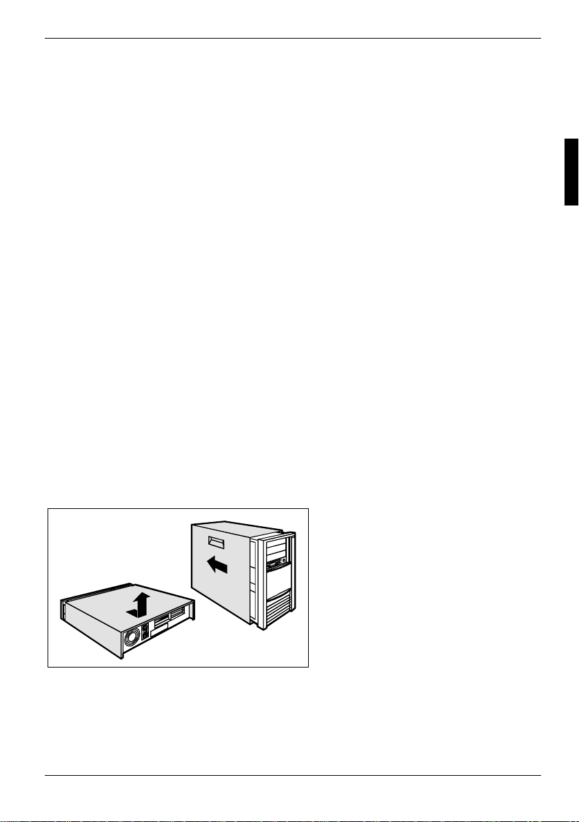
Ê Open the casing as described in the
operating manual.
A26361-D1607-Z120-1-6319 English - 7
Page 18
Brief instructions on installing mainboard
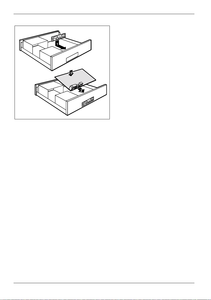
Ê Should no suitable connection field be
provided in the case, then you must
install the connection field (1) provided.
Ensure the plate is aligned properly so that
the connections are suitable for the
mainboard later.
Ê Set the mainboard on the edge on
which the connection field is located (2)
and then insert the board in the
case (3).
Make sure that spacers in the housing are
only mounted at points at which there are
mounting holes in the mainboard.
Ê Fasten the mainboard with the screws.
Ê Connect the plugs for the power supply, control panel and drives to the corresponding
connections on the mainboard.
Driver installation
Ê Install the drivers for the chipset. You may find the driver on the "Drivers & Utilities" CD. Please
refer to chapter "Drivers" for a description of installing drivers.
8 - English A26361-D1607-Z120-1-6319
Page 19
Interfaces and connectors
The positions of the interfaces and connectors are shown on page "Cover".
The components and connectors marked are not necessarily present on the mainboard.
External ports
The positions of the external ports are shown on page "Cover".
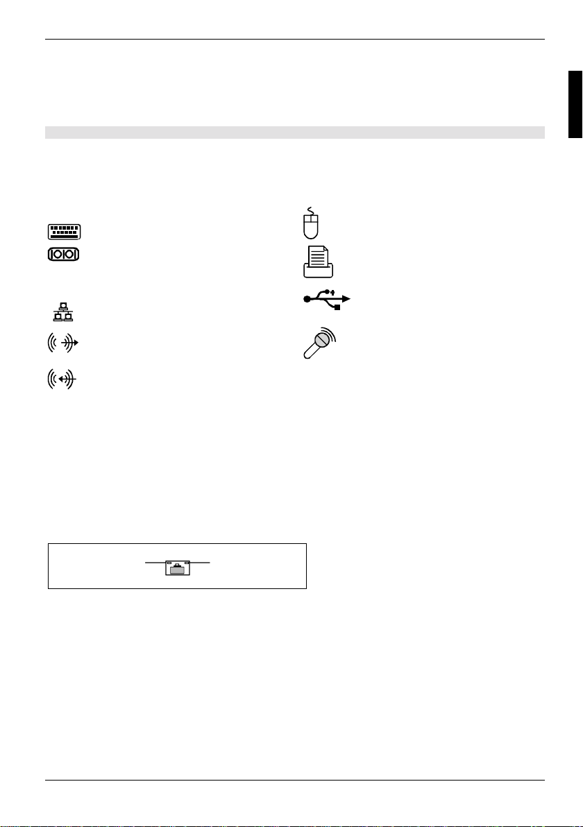
PS/2 keyboard port, purple PS/2 mouse port, green
Serial interface, turquoise
LAN
S/PDIF
* Switching over to 6-channel audio is carried out using a driver.
LAN connector USB - Universal Serial Bus, black
Audio output (Line out), light green
or Front*
Audio input (Line in), light blue
or Centre / Low*
digital 6-channel audio output, orange
1394
Parallel port/Printer, burgundy
Microphone jack, pink
or Surround*
FireWire, grey
LAN connector
This mainboard has an ADMtek AN983B LAN controller. The LAN controller is equipped with a 2 KB
transmission and receiving buffer (FIFO) and supports WOL function through Magic Packet.
The LAN RJ45 connector has two LEDs (light emitting diodes).
2
LED 1 lights green:
flashes green:
LED 2 glows yellow:
off:
1
A connection exists (e.g. to a hub).
Activity
100 Mbit/s
10 Mbit/s
A26361-D1607-Z120-1-6319 English - 9
Page 20
External ports
Audio ports and audio configuration
Audio ports
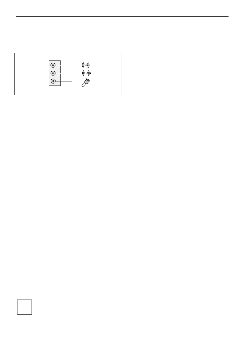
Blue
Green
Red
Connecting loudspeakers
The mainboard supports 2, 4 or 6-channel audio mode. For surround sound it is possible to connect
up to 6 analogue speakers and use the digital S/PDIF output.
Analogue 2-channel audio output
With the 2-channel configuration the functions Line-In, Line-Out and MIC are available. MIC can be
configured for operation at the front or rear of the PC (see "Audio configuration" section).
1 = Stereo L/R In
2 = Stereo L/R Out
3 = MIC In or no function (see the "Audio configuration" section)
Analogue 2-channel audio output with headphones
With the 2-channel configuration with headphones the functions Line-In, Headphones-Out and MIC
are available. MIC can be configured for operation at the front or rear of the PC (see "Audio
configuration" section).
1 = Stereo L/R In
2 = Headphones Out
3 = MIC In or no function (see the "Audio configuration" section)
Analogue 4-channel audio output
1 = Surround L/R Out
2 = Stereo L/R Out
3 = MIC
1
2
3
Analogue 6-channel audio output
The centre and subwoofer channel can be interchanged.
1 = Surround L/R Out
2 = Stereo L/R Out
3 = centre and subwoofer channel
Depending on driver, software or hardware version and operating system the functions
may differ from this presentation. If necessary, further information is provided in the
i
respective help system as well as in the "Audio configuration" section.
10 - English A26361-D1607-Z120-1-6319
Page 21

External ports
Audio configuration
The mainboard supports 2, 4 or 6-channel audio mode. For surround sound it is possible to connect
up to 6 analogue speakers and use the digital S/PDIF output (see "Audio ports" section).
Depending on the operating system used, the audio driver and additionally installed software, you
can configure the audio properties.
MIC can be configured for operation at the front or rear of the PC, if the case has a
properly connected front MIC-In (see the "Pin assignment of internal ports" section, in the
i
"Audio front panel" chapter). You can switch in the BIOS Setup or by using the software
Sigmatel JackSharing, which is either automatically installed or may be found on the CD
"Drivers & Utilities" supplied with your mainboard.
Drivers
A corresponding driver must be installed for the 2, 4 or 6-channel audio mode. If the drive is not
installed yet, proceed as described in the chapter "Add-on modules / Upgrading", in the section
"Drivers".
Software
To configure MIC-In and fully utilize all audio-functions of your Mainboard, it may be necessary to
install additional software. If the required software was not preinstalled, it can be found on the
supplied "Drivers & Utilities" CD.
BIOS
In a current BIOS MIC-In can be configured for operation at the front or rear of the PC Additional
information is contained in the "BIOS Setup" manual.
A26361-D1607-Z120-1-6319 English - 11
Page 22
Internal ports and connectors
Internal ports and connectors
The positions of the internal ports and connectors are shown on the Cover. Additional information on
some ports is also provided here.
Hard disk connection
An ultra ATA/66, ultra ATA/100 or ultra ATA/133 hard disk must be connected with a cable
especially designed for the ultra ATA/66, ultra ATA/100 or ultra ATA/133 mode.
Ê Connect the end of the cable marked with blue to the mainboard.
A serial ATA/150 hard disk must be connected with a serial ATA cable.
Ê Connect the cable to the hard disk and to the connector on the mainboard.
If you have connected one or two hard disks to a serial ATA (one hard disk is possible per serial
ATA connection), you must configure the respective settings in the BIOS Setup (further information
you can find in the BIOS Setup manual).
Audio front panel
If you want to use the internal connection for the audio front panel for the front side of the system,
then proceed as follows:
Ê Remove all plug-in jumpers from the audio front panel connection.
Ê Connect the cable for the audio front panel.
If you connect audio devices on both the front and the back of the system, you can only
use the connections Line out and Microphone once each.
i
If you have connected audio devices to both Line out connections, only the connection on
the front of the system is active.
If you have connected audio devices to both Microphone connections, only the connection
on the back of the system is active.
12 - English A26361-D1607-Z120-1-6319
Page 23
Pin assignment of internal ports
Pin assignment of internal ports
The pin assignment of some internal connections is shown in English in the following.
Some of the following connectors may be optional!
i
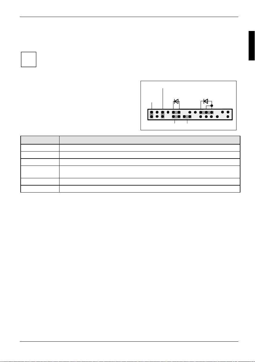
Front panel
Watch the poling of the LEDs. The positive pole of
the connection cables is often indicated with a
coloured wire.
Connection Note
Reset
Power On/Off
HD LED
Power On LED Indicates the system state APM or ACPI (see annex, "APM and ACPI system
status, energy-saving modes" section).
Password see "Settings with switches and jumpers" chapter
Recovery see "Settings with switches and jumpers" chapter
Power On/Off
1)
Reset
Power On
1)
HD-LED
Recovery Password
LED
1) 2)
1
2
A26361-D1607-Z120-1-6319 English - 13
Page 24
Pin assignment of internal ports
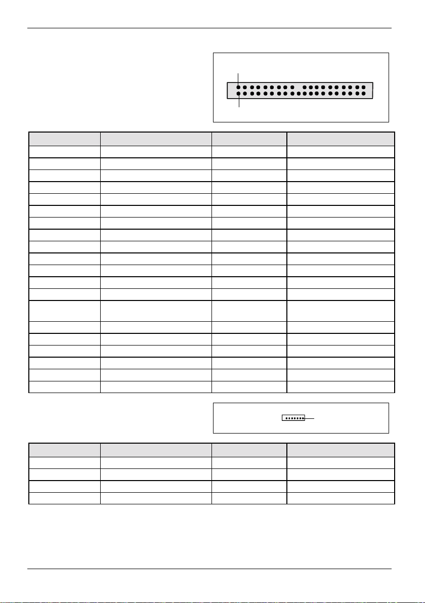
IDE interface
2
1
Pin Signal Pin Signal
1 Reset drive (low asserted) 21 DRQ (high asserted)
2GND22GND
3 Data 7 (high asserted) 23 I/O write (low asserted)
4 Data 8 (high asserted) 24 GND
5 Data 6 (high asserted) 25 I/O read (low asserted)
6 Data 9 (high asserted) 26 GND
7 Data 5 (high asserted) 27 I/O ready (high asserted)
8 Data 10 (high asserted) 28 Cable select
9 Data 4 (high asserted) 29 DAK (low asserted)
10 Data 11 (high asserted) 30 GND
11 Data 3 (high asserted) 31 IRQ (high asserted)
12 Data 12 (high asserted) 32 not connected
13 Data 2 (high asserted) 33 ADR 1 (high asserted)
14 Data 13 (high asserted) 34 ATA 66 Detect (low
15 Data 1 (high asserted) 35 ADR 0 (high asserted)
16 Data 14 (high asserted) 36 ADR 2 (high asserted)
17 Data 0 (high asserted) 37 CS 1 (low asserted)
18 Data 15 (high asserted) 38 CS 3 (low asserted)
19 GND 39 IDE-LED (low asserted)
20 Key 40 GND
asserted)
Serial ATA (internal)
Pin Signal Pin Signal
1 GND 2 Transmit data positive
3 Transmit data negative 4 GND
5 Receive data negative 6 Receive data positive
7GND 8 Key
14 - English A26361-D1607-Z120-1-6319
1
Page 25
Pin assignment of internal ports
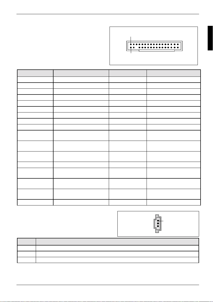
Floppy interface
2
1
Pin Signal Pin Signal
1 GND 18 Step DIR (low asserted)
2 FDHDIN (low asserted) 19 GND
3 GND 20 Step Pulse (low asserted)
4 not connected 21 GND
5 Key 22 Write Data (low asserted)
6 not connected 23 GND
7 GND 24 Write Enable (low asserted)
8 Index (low asserted) 25 GND
9 GND 26 Track 0 (low asserted)
10 Motor A Enable (low
asserted)
11 GND 28 Write Protect (low
12 Drive B Select (low
asserted)
13 GND 30 Read Data (low asserted)
14 Drive A Select (low
asserted)
15 GND 32 Side 1 Select (low
16 Motor B Enable (low
asserted)
17 GND 34 Disk Change (low asserted)
27 GND
29 GND
31 GND
33 GND
asserted)
asserted)
Audio S/PDIF In
Pin Signal
1VCC
2 SPDIF in
3GND
A26361-D1607-Z120-1-6319 English - 15
1
Page 26
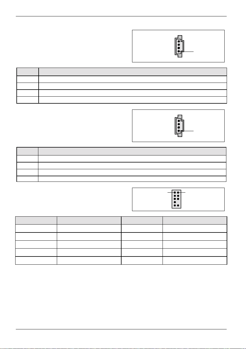
Pin assignment of internal ports
AUX audio in
1
Pin Signal
1 Left AUX audio input
2 Analogue GND
3 Analogue GND
4 Right AUX audio input
CD-ROM audio in
1
Pin Signal
1 Left CD audio input
2CD GND
3CD GND
4 Right CD audio input
Audio front panel
Pin Signal Pin Signal
1 Micro input 2 Analogue GND
3 Micro bias 4 Analogue VCC
5 Right line output 6 Right line return
7 not connected 8 Key
9 Left line output 10 Left line return
If the audio front panel is not used, you must plug jumpers on pin pairs 5/6 and 9/10.
16 - English A26361-D1607-Z120-1-6319
1 2
Page 27
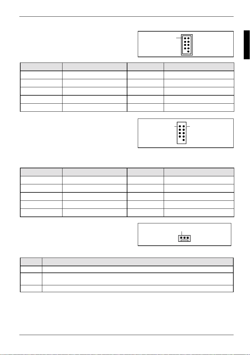
Pin assignment of internal ports
FireWire / IEEE 1394
Pin Signal Pin Signal
1 TPA+ 2 TPA3 GND 4 GND
5 TPB+ 6 TPB7 +12 V 8 +12 V
9 Key 10 GND
USB E/G - dual channel F/H - dual channel
(internal or external via special cable)
Pin Signal Pin Signal
1 VCC C 2 VCC D
3 Data negative C 4 Data negative D
5 Data positive C 6 Data positive D
7 GND 8 GND
9 Key 10 not connected
1
1 2
Fan 1
1
Fan 2
(processor fan - only for 3 pin fans)
Pin Signal
1GND
2 Controlled Fan voltage (0 V, +6 V...+12 V, max. 1 A)
3 Fan sense
A26361-D1607-Z120-1-6319 English - 17
or fix Fan voltage (+12 V, max. 1 A)
Page 28
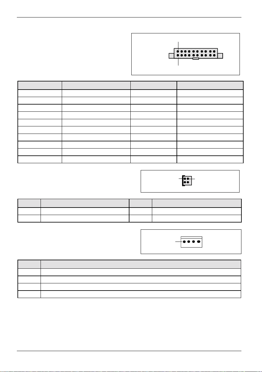
Pin assignment of internal ports
Power supply ATX
1
11
Pin Signal Pin Signal
1 +3.3V(P2V2P) 11 +3.3V(P2V2P)
2 +3.3V(P2V2P) 12 -12V (P12VN)
3GND13GND
4 +5V (VCC) 14 PS on (low asserted)
5GND15GND
6 +5V (VCC) 16 GND
7GND17GND
8 Powergood (high asserted) 18 -5V (5PVN)
9 +5V Auxiliary (VCC Aux) 19 +5V (VCC)
10 +12V (P12VP) 20 +5V (VCC)
Power supply ATX12 V 13
Pin Signal Pin Signal
1 GND 2 GND
3 +12 V 4 +12 V
SMB for Temperature sensor
Pin Signal
1 P3V3P_DUAL
2 SMB_PIC_CLK_H
3 SMB_PIC_DATA_H
4GND
18 - English A26361-D1607-Z120-1-6319
1
Page 29
Settings with switches and jumpers
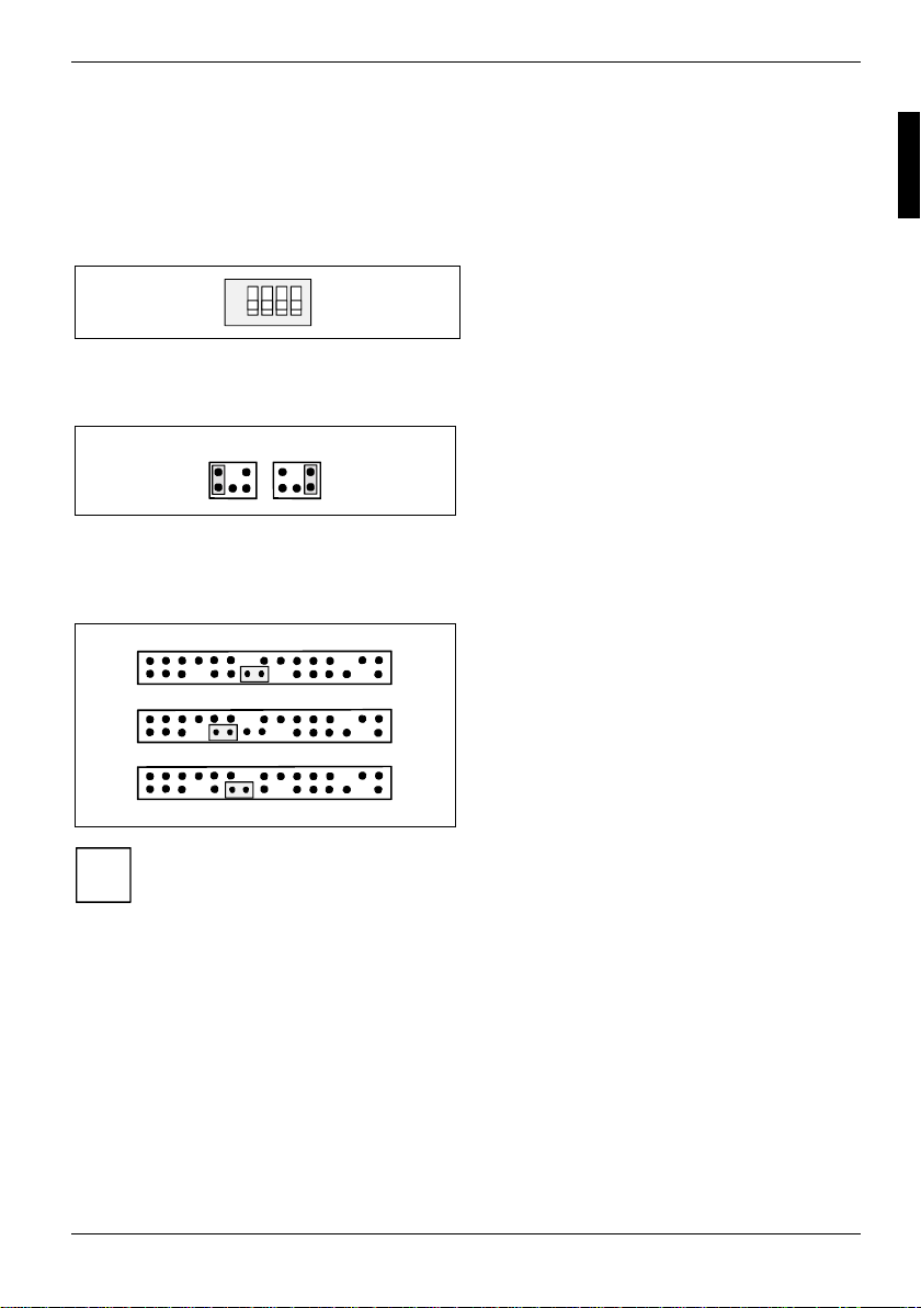
Your mainboard is optionally equipped with switches or jumpers. The positions of the switches or
jumpers are shown on page "Cover".
Setting with switches
ON
1234
Setting with jumpers
21
Setting via control-panel plug connector
Switch 1 = Skipping system and BIOS Setup
password
Switch 2 = System BIOS recovery
Switch 3 = must be set to
Switch 4 = must be set to off
Pin pair 1 inserted =
Skipping system and BIOS Setup password
Pin pair 2 inserted =
System BIOS recovery
Any other setting =
State of supply; jumper has no function
off
A
B
C
Please pay attention on the exact position of the pin pairs!
i
A26361-D1607-Z120-1-6319 English - 19
1
2
1
2
1
2
Pin pair A inserted =
Skipping system and BIOS Setup password
Pin pair B inserted =
System BIOS recovery
Pin pair C inserted =
factory setting
Page 30

Pin assignment of internal ports
Skipping system and BIOS Setup password - switch 1 / pin pair 1 / pin pair A
Switch 1 / pin pair 1 / pin pair A enables skipping the system and BIOS Setup password.
On / inserted System and BIOS Setup password are skipped when the device is switched on and
Off / not inserted
Recovering System BIOS - switch 2 / pin pair 2/ pin pair B
Switch 2 / pin pair 2 / pin pair B enables recovery of the old system BIOS after an attempt to update
has failed. To restore the old BIOS you need a Flash BIOS Diskette (see "BIOS update" chapter).
On / inserted The System BIOS executes from floppy drive A: and the inserted "Flash-BIOS-
Off / not inserted
Reserved - switch 3 and switch 4 (if present)
Switch 3 and 4 are reserved. The position of the switch doesn't matter.
may be changed.
System and BIOS Setup password must be entered when the device is switched on.
Diskette" restores the System BIOS on the mainboard.
Normal operation (default setting).
20 - English A26361-D1607-Z120-1-6319
Page 31
Add-on modules / Upgrading
Exit energy-saving mode, switch off the system and remove the power plug from the
mains outlet, before carrying out any of the procedures described in this chapter!
!
Even when you have switched off the device, parts (e.g. memory modules, AGP and PCI
extension boards) are still supplied with power.
Replacing processor
Technical data
• AMD Athlon
A current list of the processors supported by this mainboard is available on the Internet at:
www.fujitsu-siemens.com/mainboards.
TM
64 with HyperTransportTM Link (1600 MT/s) in the mPGA754 design.
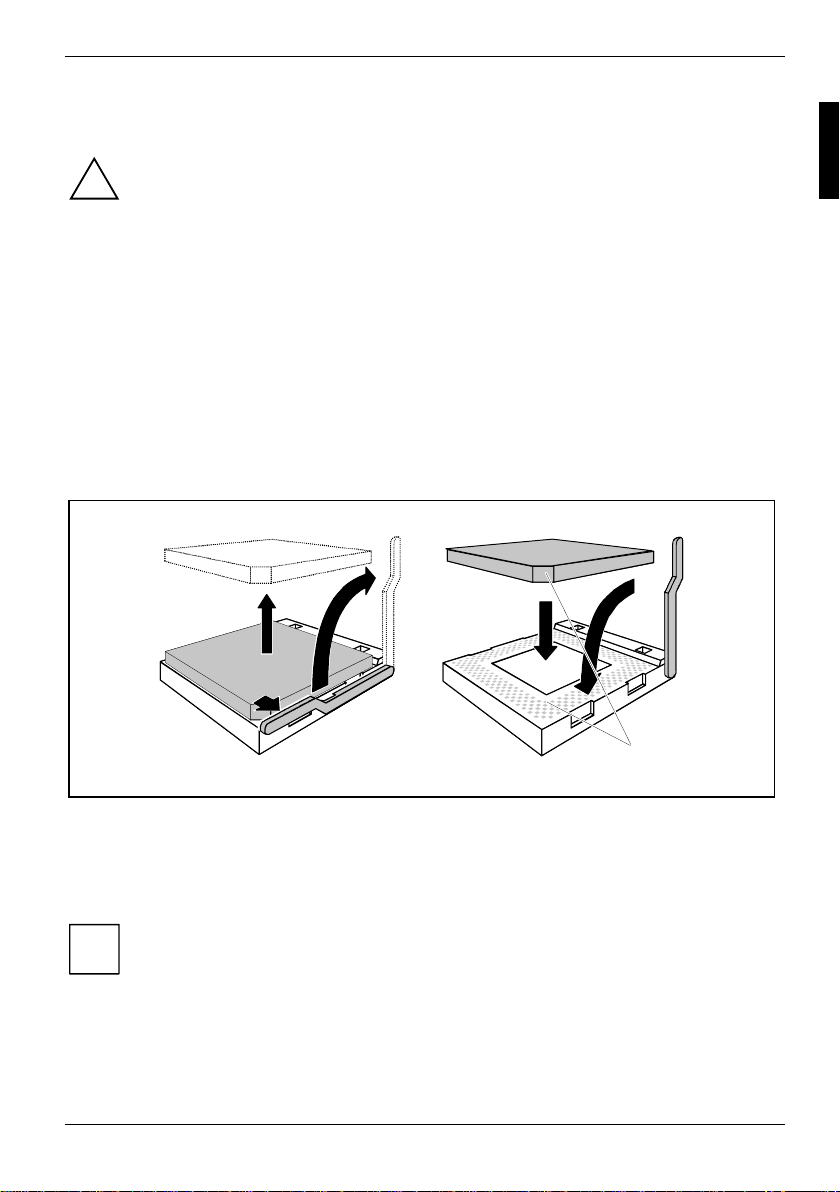
Removing and installing processors
Ê Remove the fan that there may be and the heat sink.
2
2
3
3
1
1
Ê Pull the lever in the direction of the arrow (1) and lift it as far as it will go (2).
Ê Remove the old processor from the socket (3).
Ê Insert the new processor in the socket so that the angled corner of the processor matches the
coding on the socket (A) with regard to the position (4).
4
4
5
5
A
A
The angled corner of the processor can also be at a different location than shown in the
illustration.
i
Ê Push the lever back down until it clicks into place (5).
A26361-D1607-Z120-1-6319 English - 21
Page 32
Replacing processor
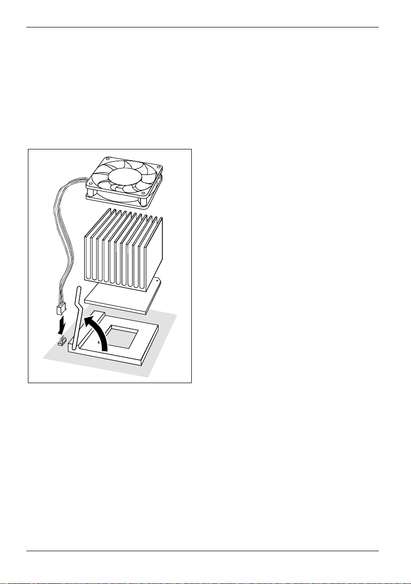
Mounting heat sink
Be sure to use heat conducti ng material between the processor and the heat sink. If a heat
conducting pad (rubber-like foil) i s already applied to the heat sink, then use it. Otherwise you must
apply a very thin layer of heat conduct i ng paste.
Heat conducting pads can only be used once. If you remove the heat sink, you must clean it and
apply new heat conducting paste before you remount it.
Please note that, depending on the heat sink used, different heat sink mounts are required on the
mainboard.
Ê Depending on the configuration variant, you
must pull a protect i ve foil off the heat sink or
coat the heat sink with heat c onducting paste
before fitting it.
Depending on the processor variant, clips may
also be supplied for mounti ng the heat sink that fix
it in place.
Ê When you have mounted the optional fan,
connect the fan plug to the c orresponding
connection on the mainboard.
Schematic illustration
22 - English A26361-D1607-Z120-1-6319
Page 33
Upgrading main memory
Upgrading main memory
Technical data
Technology: DDR 333 or DDR 400 unbuffered DIMM modules
Size: 128 Mbyte up to 2 Gbyte
Granularity: 128, 256, 512 or 1024 Mbyte for one socket
A current list of the memory modules recommended for this mainboard is available on the Internet
www.fujitsu-siemens.com/mainboards.
at:
At least one memory module must be installed.
Memory modules with different memory capacities can be combined.
!
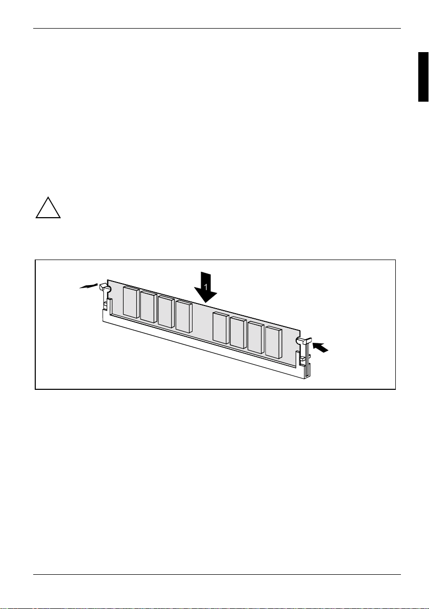
Installing a memory module
184-Pin; 2.5 V; 64 Bit, with or without ECC
You may only use unbuffered 2,5 V memory modules. Buffered memory modules are not
supported. ECC is supported.
DDR-DRAM memory modules must meet the PC2700 or PC3200 specification.
2
2
Ê Push the holders on each side of the memory slot outwards.
Ê Insert the memory module into the location (1).
Ê At the same time flip the lateral holders upwards until the memory module snaps in place (2).
A26361-D1607-Z120-1-6319 English - 23
Page 34
Upgrading AGP screen controllers
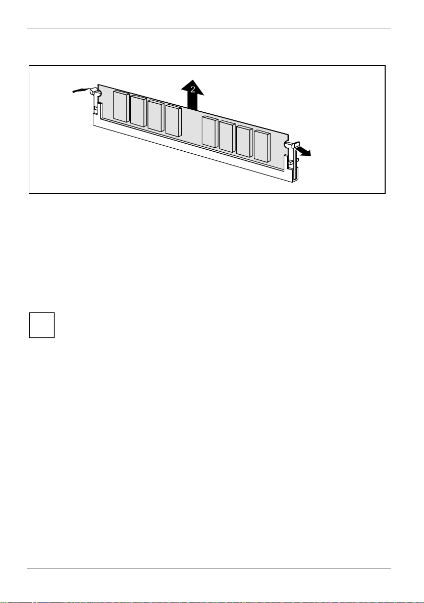
Removing a memory module
1
1
Ê Push the clips on the right and left of the memory slot outward (1).
Ê Pull the memory module out of the memory slot (2).
Upgrading AGP screen controllers
Technical data:
The AGP slot supports the modes 2x/4x/8x with 32 bits and 66 MHz. Only 1.5 V AGP graphics cards
are supported.
Some older 3.3 V AGP graphics cards are coded like 1.5 V AGP graphics cards. The
installation of such 3.3 V AGP graphics cards can cause serious damage to the
i
mainboard and the AGP graphics cards.
Adding PCI cards
Technical data:
32 bit / 33 MHz PCI slots
5 V and 3.3 V supply voltage
3.3 V auxiliary voltage
24 - English A26361-D1607-Z120-1-6319
Page 35
Adding PCI cards
PCI bus interrupts - Selecting correct PCI slot
To achieve optimum stability, performance and compatibility, avoid the multiple use of
ISA IRQs or PCI IRQ Lines (IRQ sharing). Should IRQ sharing be unavoidable, then all
i
involved devices and their drivers must support IRQ sharing.
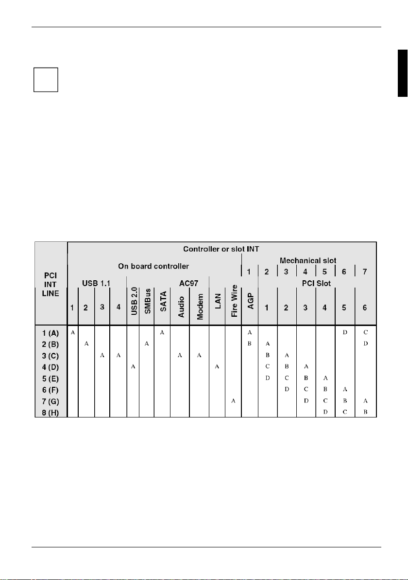
PCI IRQ Lines connect AGP slots, PCI slots and onboard components to the interrupt controller.
PCI IRQ Lines are permanently wired on the mainboard.
Which ISA IRQs are assigned to the PCI IRQ Lines is normally automatically specified by the BIOS
(see description in "BIOS Setup").
Monofunctional expansions cards:
Standard AGP and PCI expansion cards require a maximum of one interrupt, which is called the PCI
interrupt INT A. Expansion cards that do not require an interrupt can be installed in any desired slot.
Multifunctional expansion cards or expansion cards with integrated PCI-PCI bridge:
These expansion cards require up to four PCI interrupts: INT A, INT B, INT C, INT D. How many and
which of these interrupts are used is specified in the documentation provided with the card.
The assignment of the PCI interrupts to the PCI IRQ Lines is shown in the following table:
Use the first PCI slots that have a single PCI IRQ Line (no IRQ sharing). If you must use another
PCI slot with IRQ sharing, check whether the expansion card properly supports IRQ sharing with the
other devices on this PCI IRQ Line. The drivers of all cards and components on this PCI IRQ Line
must also support IRQ sharing.
A26361-D1607-Z120-1-6319 English - 25
Page 36
Adding PCI cards
Replacing the lithium battery
In order to permanently save the system information, a lithium battery is installed to provide the
CMOS-memory with a current. A corresponding error message noti fies the user when the charge is
too low or the battery is empty. The lithium battery must then be replaced.
Incorrect replacem ent of the lithium batt ery may lead to a risk of explosion!
!
The lithium battery may be replaced only with an identical battery or with a type
recommended by the m anufacturer.
Do not throw lithium batteries i nto the household waste. They must be disposed of in
accordance with local regulations concerning special waste.
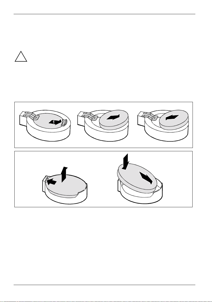
Make sure that you insert the bat t ery the right way round. The plus pole must be on the
top!
The lithium battery holder exist s in different designs t hat function in the same way.
2
4
2
1
3
3
Ê Press the locking lug in the direction of the arrow; the battery jumps somewhat out of the
holder (1).
Ê Remove the battery (2).
Ê Push the new lithium battery of the identical type into the holder (3) and press it downward until
it engages (4).
26 - English A26361-D1607-Z120-1-6319
Page 37
BIOS update
BIOS update
When should a BIOS update be carried out?
Fujitsu Siemens Computers makes new BIOS versions available to ensure compatibility to new
operating systems, new software or new hardware. In addition, new BIOS functions can also be
integrated.
A BIOS update should always also be carried out when a problem exists that cannot be solved with
new drivers or new software.
Where can I obtain BIOS updates?
The BIOS updates are available on the Internet at www.fujitsu-siemens.de/mainboards.
How does a BIOS update work?
You have two ways of doing this:
1. BIOS update under DOS with bootable BIOS update floppy disk - brief description
Ê Download the update file from out website to your PC.
Ê Insert an empty floppy disk (1.44 MB).
Ê Run the update file (e.g. 1607103.EXE).
Ê A bootable update floppy disk is created. Leave this floppy disk in the drive.
Ê Restart the PC.
Ê Follow the instructions on screen.
Detailed information on the BIOS update under DOS is provided in the manual on "BIOS
Setup" ("Drivers & Utilities" CD).
i
2. BIOS update under Windows with DeskFlash utility
A BIOS update can also be carried out directly under Windows with the DeskFlash utility. DeskFlash
is contained on the "Drivers & Utilities" CD (under DeskUpdate).
BIOS Recovery - Recovering System BIOS
All BIOS settings are reset to the default values.
i
Ê Open the casing as described in the operating manual.
Ê Set the switch for "Restore system BIOS" to ON.
Ê Close the casing as described in the operating manual.
Ê Insert a BIOS update floppy disk and start the PC.
Ê Note the signals issued from the loudspeaker. You have successfully restored the BIOS if you
hear the signal sequence "short-short- long- long- long" and the diskette access indicator is
dark. This can take a few minutes.
Ê Open the casing as described in the operating manual.
Ê Set the switch for "Restore system BIOS" to OFF.
A26361-D1607-Z120-1-6319 English - 27
Page 38

Drivers
Ê Close the casing as described in the operating manual.
Ê Remove the floppy disk from the drive.
Ê Start the PC and invoke BIOS Setup.
Ê Select the menu item Reset Configuration in the menu Advanced and change the setting to
Yes.
Ê Save the change and terminate BIOS Setup.
The BIOS recovery has now been completed. The system restarts.
Detailed information on the BIOS recovery is contained in the manual "BIOS Setup"
("Drivers & Utilities" CD).
i
Drivers
Only when no drivers are installed on your system, or you want to update these, proceed as follows:
Ê Insert the CD "Drivers & Utilities Collection" into the CD-ROM drive.
Ê If the CD does not start automatically, run the START.EXE programme in the main directory of
the CD.
Ê Select DeskUpdate - Fully automatic installation.
Follow the instructions on screen.
28 - English A26361-D1607-Z120-1-6319
Page 39
Annex
Electrical Properties
Loadability for connections and fuses
Make sure that the connected devices do not overload the connections.
i
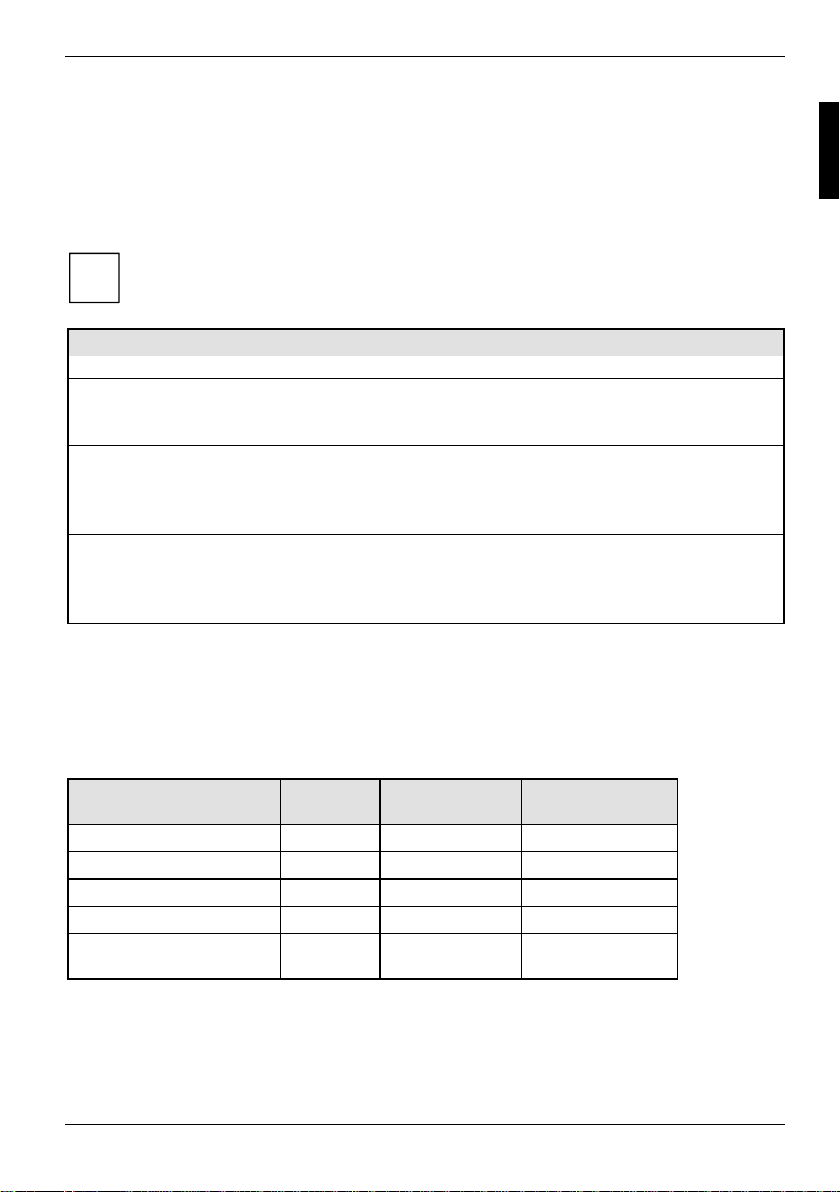
Fuse no. Fuse Connection Maximum loadability
- - Fan1, Fan2 1000 mA each
1 750 mA Keyboard Not specified
Mouse Not specified
VGA port Minimum 50 mA
2 2000 mA USB port A
USB port B
USB port C
USB port D
3 2000 mA USB port E
USB port F
USB port G
USB port H
The fuses on this mainboard can be used several times (polyfuses). Shortly after the error state has
been eliminated, the fuses reset to the original state.
500 mA
500 mA
Mainboard current requirement (TBD)
You require a Pentium4 power supply nit as per the ATX12V specification for this mainboard. If you
do not have a PC from Fujitsu Siemens Computers, make sure that the power supply unit provides
the required amperages.
Resource Voltage Maximum
ATX12V power supply +12 V ±5 % 7,8 A (12,0 A)
ATX12V power supply -12 V ±10 % 0,05 A
ATX12V power supply +5,0 V ±5 % 1,1 A (19,5 A)
ATX12V power supply +3,3 V ±5 % 4 A
Standby voltage of power
supply unit
The specifications apply to the onboard components and represent the least favourable case. In
addition, at least 350 mA is required for PCI on 3.3 V, and 500 mA per connected device for USB on
5 V.
* The values in clamps are the maximal values. The values before the clamps are the typical
values.
A26361-D1607-Z120-1-6319 English - 29
+5,0 V SB ±5 % 2 A
difference
Current typ. (max.)*
Page 40
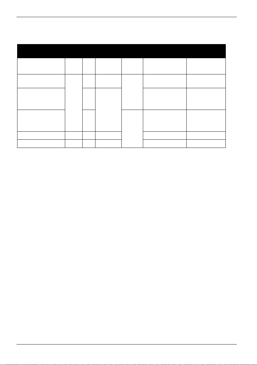
APM and ACPI system status, energy-saving modes
APM and ACPI system status, energy-saving modes
System status ACPI
Normal operation G0 S0 On On Normal
Simple energy-
saving mode
Maximum energy-
saving mode **
"Save to DRAM"
Maximum energy-
saving mode **
"Save To Disk"
“Soft Off" G2 S5 Soft Off Nearly zero Full boot time
Mechanically Off G3 Off
* G = Global status; S = System status
** The power supply unit must provide sufficiently loadable 5 V standby voltage.
To use the WOL functionality the power supply must provide a 5 V auxiliary voltage (5V SB) of at
least 1 A.
Status*
G1
APM
Status
S1 Standby Almost like
S3
S4 Wake-up
Power
LED
flashin
g
Off
Power
consumption
normal
RAM,
wake-up
components
components
Zero Full boot time
Wake-up time
Almost
immediately
approx. 5 s
approx. 20 s
30 - English A26361-D1607-Z120-1-6319
Page 41
Mainboard Revision and BIOS Version
Mainboard Revision and BIOS Version
The compatibility, e.g. with new processors, can be independent of the BIOS version or the revision
status of the mainboard used. The CPU and BIOS compatibility lists are available on the Internet at
www.fujitsu-siemens.de/mainboards.
Mainboard Revision
The revision status of the mainboard exactly identifies which mainboard you have. It is indicated on
a sticker on the edge of the mainboard:
D1607-G12 GS 1
05618476
Example Mainboard-Revision
BIOS version
The BIOS version can be displayed in the BIOS Setup.
Ê Press F2 during booting to open the BIOS Setup.
Ê Press F1.
The BIOS version is specified on the displayed information page under the entry
BIOS Release.
A26361-D1607-Z120-1-6319 English - 31
Page 42

Error messages
This chapter contains error messages generated by the mainboard.
Available CPUs do not support the same bus frequency - System halted!
Memory type mixing detected
Non Fujitsu Siemens Memory Module detected - Warranty void
There are more than 32 RDRAM devices in the system
Check whether the system configuration has changed. If necessary, correct the settings.
Check date and time settings
The system date and time are invalid. Set the current date and time in the Main menu of the
BIOS Setup.
CPU ID 0x failed
Switch the server off and on again. If the message is still displayed, go into the BIOS setup and
set the corresponding processor to
your sales outlet or customer service centre.
CPU mismatch detected
You have replaced the processor or changed the frequency setting. As a result, the
characteristic data of the processor have changed. Confirm this change by running the
Setup
and exiting it again.
Diskette drive A error
Diskette drive B error
Check the entry for the diskette drive in the Main menu of the BIOS Setup. Check the
connections to the diskette drive.
DMA test failed
EISA CMOS not writable
Extended RAM Failed at offset: nnnn
Extended RAM Failed at address line: nnnn
Failing Bits: nnnn
Fail-Safe Timer NMI failed
Multiple-bit ECC error occurred
Memory decreased in size
Memory size found by POST differed from EISA CMOS
Single-bit ECC error occurred
Software NMI failed
System memory exceeds the CPU’s caching limit
System RAM Failed at offset: nnnn
Shadow RAM Failed at offset: nnnn
Switch the device off and on again. If the message is still displayed, please contact your sales
outlet or customer service centre.
Failure Fixed Disk 0
Failure Fixed Disk 1
Fixed Disk Controller Failure
Check the entry for the hard disk drive in the Main menu and the entry for the IDE drive
controller in the
disk drive's connections and jumpers.
Advanced - Peripheral Configuration menu of the BIOS Setup. Check the hard
Disabled in the Server - CPU Status menu; please contact
BIOS
32 - English A26361-D1607-Z120-1-6319
Page 43

Mainboard Revision and BIOS Version
Incorrect Drive A - run SETUP
Incorrect Drive B - run SETUP
Correct the entry for the diskette drive in the Main menu of the BIOS Setup.
Invalid NVRAM media type
Switch the device off and on again. If the message is still displayed, please contact your sales
outlet or customer service centre.
Invalid System Configuration Data
In the Advanced menu of the BIOS Setup set the entry Reset Configuration Data to Yes.
Invalid System Configuration Data - run configuration utility
Press F1 to resume, F2 to Setup
This error message may be displayed if the machine was switched off during system start-up.
Call
BIOS Setup and switch to the Advanced menu. Select the menu item Reset Configuration
Data
and change the setting to Yes. Save the change and terminate BIOS Setup. Reboot the
device.
Keyboard controller error
Connect another keyboard or another mouse. If the message is still displayed, please contact
your sales outlet or customer service centre.
Keyboard error
Check that the keyboard is connected properly.
Keyboard error nn
nn Stuck Key
Release the key on the keyboard (nn is the hexadecimal code for the key).
Missing or invalid NVRAM token
Switch the device off and on again. If the message is still displayed, please contact your sales
outlet or customer service centre.
Monitor type does not match CMOS - RUN SETUP
Correct the entry for the monitor type in the Main menu of the BIOS Setup.
On Board PCI VGA not configured for Bus Master
In the BIOS Setup, in the Advanced menu, submenu PCI Configuration, set the Shared PCI
Master Assignment
One or more RDRAM devices are not used
One or more RDRAM devices have bad architecture/timing
One or more RDRAM devices are disabled
Contact your system administrator or contact our customer service centre.
Operating system not found
Check the entries for the hard disk drive and the floppy disk drive in the Main menu and the
entries for
Parity Check 1
Parity Check 2
Boot Sequence submenu of the BIOS Setup.
Switch the device off and on again. If the message is still displayed, please contact your sales
outlet or customer service centre.
Previous boot incomplete - Default configuration used
By pressing function key F2 you can check and correct the settings in BIOS Setup. By pressing
entry to VGA.
A26361-D1607-Z120-1-6319 English - 33
Page 44

Mainboard Revision and BIOS Version
function key F1 the system starts with incomplete system configuration. If the message is still
displayed, please contact your sales outlet or customer service centre.
Real time clock error
Call the BIOS Setup and enter the correct time in the Main menu. If the message is still
displayed, please contact your sales outlet or customer service centre.
Service Processor not properly installed
The server management controller has not been correctly installed. If the message is still
displayed, please contact your sales outlet or customer service centre.
Storage Extension Group = xy
Configuration error, x Storage Extensions(s) found, configured are y
SE(s).
Device List: k1, k2 ...
The specified number of storage expansion units (SEs) in the BIOS Setup menu Server -
Storage Extensions - Number of connected SE
group are connected at the server and change the setting in
have assigned the same device ID twice.
xy = Group number
x = Number of SEs found on the communication bus
y = Number of SEs entered in
k1, k2 ... = Device ID of the storage extensions found
System battery is dead - Replace and run SETUP
Replace the lithium battery on the mainboard and redo the settings in the BIOS Setup.
System Cache Error - Cache disabled
Switch the device off and on again. If the message is still displayed, please contact your sales
outlet or customer service centre.
System CMOS checksum bad - - Default configuration used
Call the BIOS Setup and correct the previously made entries or set the default entries.
System Management Configuration changed or Problem occurred
A system fan or system sensor has failed. Check the hardware operation.
System timer error
Switch the device off and on again. If the message is still displayed, please contact your sales
outlet or customer service centre.
Uncorrectable ECC DRAM error
DRAM Parity error
Unknown PCI error
Switch the device off and on again. If the message is still displayed, please contact your sales
outlet or customer service centre.
Verify CPU frequency selection in Setup
The frequency setting for the processor is invalid. Correct the BIOS Setup and the setting.
Number of connected SE
is incorrect. Check how many SEs within the
BIOS Setup. Check whether you
34 - English A26361-D1607-Z120-1-6319
Page 45
Glossary
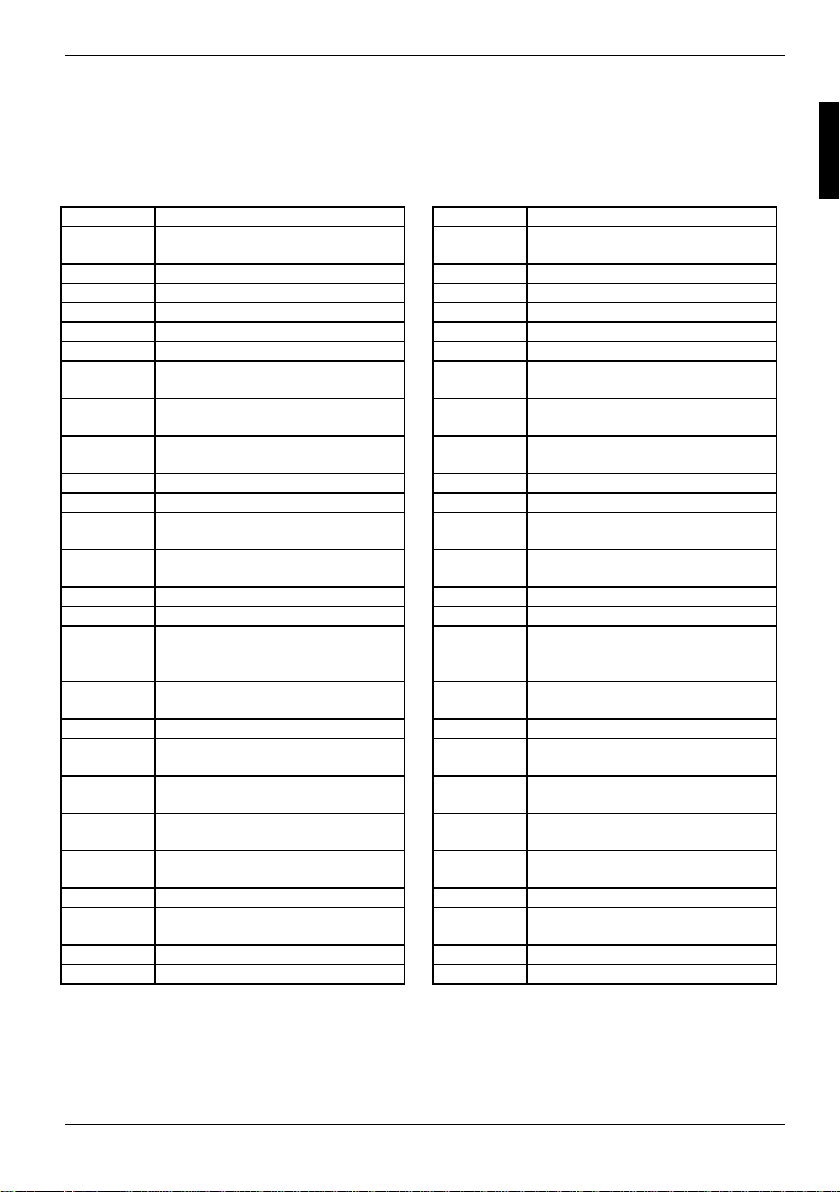
Glossary
The technical terms and abbreviations given below represent only a selection of the full list of
common technical terms and abbreviations.
Not all technical terms and abbreviations listed here are valid for the described mainboard.
AC'97 Audio Codec '97 IPSEC Internet Protocol Security
ACPI Advanced Configuration and
Power Management Interface
AGP Accelerated Graphics Port LAN Local Area Network
AMR Audio Modem Riser LSA LAN Desk Service Agent
AOL Alert On LAN MCH Memory Controller Hub
APM Advanced Power Management MMX MultiMedia eXtension
ASF Alert Standard Format MT/s Mega Transfers per second
ATA Advanced Technology
Attachment
BIOS Basic Input Output System PCI Peripheral Component
BMC Baseboard management
controller
CAN Controller Area Network PXE Preboot eXecution Environment
CNR Communication Network Riser RAM Random Access Memory
CPU Central Processing Unit RAMDAC Random Access Memory Digital
C-RIMM Continuity Rambus Inline
Memory Module
DIMM Dual Inline Memory Module RIMM Rambus Inline Memory Module
ECC Error Correcting Code RTC Real Time Clock
EEPROM Electrical Erasable
Programmable Read Only
Memory
FDC Floppy disk controller SATA Serial ATA (Advanced
FIFO First-In First-Out SB Soundblaster
FSB Front Side Bus SDRAM Synchronous Dynamic Random
FWH Firmware Hub SGRAM Synchronous Graphic Random
GMCH Graphics and Memory Controller
Hub
GPA Graphics Performance
Accelerator
I2C Inter Integrated Circuit SVGA Super Video Graphic Adapter
IAPC Instantly Available Power
Managed Desktop PC Design
ICH I/O Controller Hub VGA Video Graphic Adapter
IDE Intelligent Drive Electronics WOL Wake On LAN
ISA Industrial Standard Architecture
P64H PCI64 Hub
PSB Processor System Bus
RDRAM Rambus Dynamic Random
S/PDIF Sony/Philips Digital Interface
SIMD Streaming Mode Instruction
SMBus System Management Bus
USB Universal Serial Bus
Interconnect
Analogue Converter
Access Memory
Technology Attachment)
Access Memory
Access Memory
Single Instruction Multiple Data)
(
A26361-D1607-Z120-1-6319 English - 35
 Loading...