

Page 1

Mainboard D1419
Deutsch / English
2
Technisches Handbuch / Technical Manual
Page 2

Sie haben ...
... technische Fragen oder Probleme?
Wenden Sie sich bitte an:
• Ihren zuständigen Vertriebspartner
• Ihre Verkaufsstelle
Weitere Informationen finden Sie im Handbuch "Sicherheit und Ergonomie".
Aktuelle Informationen zu unseren Produkten, Tipps, Updates usw. finden Sie im Internet:
http://www.fujitsu-siemens.com
Are there ...
... any technical problems or other questions you need clarified?
Please contact:
• your sales partner
• your sales outlet
You will find further information in the manual "Safety and Ergonomics".
The latest information on our products, tips, updates, etc., can be found on the Internet under:
http://www.fujitsu-siemens.com
Page 3

Page 4

Dieses Handbuch wurde auf Recycling-Papier gedruckt.
This manual has been printed on recycled paper.
Ce manuel est imprimé sur du papier recyclé.
Este manual ha sido impreso sobre papel reciclado.
Questo manuale è stato stampato su carta da riciclaggio.
Denna handbok är tryckt på recyclingpapper.
Dit handboek werd op recycling-papier gedrukt.
Bestell-Nr./Order No.:
Printed in the Federal Republic of Germany
AG 0303 03/03
A26361-D1419-Z120-1-7419
A26361-D1419-Z120-1-7419
Page 5

Mainboard D1419
Technisches Handbuch
Technical Manual
Deutsch
English
Ausgabe März 2003
March 2003 edition
Page 6

Intel ist ein eingetragenes Warenzeichen der Intel Corporation, USA.
PS/2 ist ein eingetragenes Warenzeichen von International Business Machines, Inc.
Alle weiteren genannten Warenzeichen sind Warenzeichen oder eingetragene Warenzeichen
der jeweiligen Inhaber und werden als geschützt anerkannt.
Alle Rechte vorbehalten, insbesondere (auch auszugsweise) die der Übersetzung, des
Nachdrucks, der Wiedergabe durch Kopieren oder ähnliche Verfahren.
Zuwiderhandlungen verpflichten zu Schadenersatz.
Alle Rechte vorbehalten, insbesondere für den Fall der Patenterteilung oder GM-Eintragung.
Liefermöglichkeiten und technische Änderungen vorbehalten.
Copyright ã Fujitsu Siemens Computers GmbH 2003
Intel is a registered trademark of Intel Corporation, USA.
PS/2 is a registered trademark of International Business Machines, Inc.
All other trademarks referenced are trademarks or registered trademarks of their respective
owners, whose protected rights are acknowledged.
All rights, including rights of translation, reproduction by printing, copying or similar methods,
even of parts are reserved.
Offenders will be liable for damages.
All rights, including rights created by patent grant or registration of a utility model or design,
are reserved. Delivery subject to availability.
Right of technical modification reserved.
Page 7

Contents
Introduction........................................................................................................................................1
Notational conventions ..............................................................................................................1
Important notes..................................................................................................................................1
Information about boards ...........................................................................................................2
Features............................................................................................................................................3
Interfaces and connectors..........................................................................................................4
Temperature / System monitoring..............................................................................................5
LAN connector...........................................................................................................................6
ISA bus resources.....................................................................................................................6
PCI bus resources .....................................................................................................................7
PCI slots............................................................................................................................7
PCI IRQ line x - Assignment of the PCI interrupts..............................................................7
Screen resolution.......................................................................................................................8
SCSI/Host RAID configuration utility..........................................................................................9
Starting the SCSI/Host RAID configuration program..........................................................9
Terminating the SCSI/Host RAID configuration program....................................................9
Activating and Configuring Host RAID .............................................................................10
Default Settings in the menu Configure/View SCSI Controller Settings............................11
SCSI Bus Interface Definitions.........................................................................................12
Additional Options............................................................................................................12
SCSI Device Configuration ..............................................................................................13
Advanced Configuration Options......................................................................................14
SCSI Disk Utilities....................................................................................................................15
Verify ...............................................................................................................................15
Settings with switches .....................................................................................................................16
Add-on modules ..............................................................................................................................17
Glossary..........................................................................................................................................23
Format Disk .....................................................................................................................15
Recovering System BIOS - switch 1........................................................................................16
Skipping the password query - switch 2...................................................................................16
Write protection for Flash BIOS - switch 3 ............................................................................... 16
Write protection for floppy disks - switch 4............................................................................... 16
Slot sequence..........................................................................................................................18
Installing the processor with heat sink and fan......................................................................... 19
Mounting heat sink...........................................................................................................19
Upgrading main memory..........................................................................................................20
Replacing lithium battery..........................................................................................................22
A26361-D1419-Z120-1-7419
Page 8

Page 9

Introduction
This technical manual describes the mainboard D1419, which can be equipped with up to two Intel
processors.
You will find further information in the "BIOS Setup" description.
Further information about drivers is provided in the readme files on the hard disk, on the supplied
drivers diskettes, on the "Drivers & Utilities" or on the "ServerStart" CD.
Notational conventions
The meanings of the symbols and fonts used in this manual are as follows:
Pay particular attention to text marked with this symbol. Failure to observe this warning
endangers your life, destroys the device, or may lead to loss of data.
!
Supplementary information, remarks, and tips follow this symbol.
i
Ê Text which follows this symbol describes activities that must be performed in the order shown.
Ë This symbol indicates that you must enter a blank space (press the Space Bar) at this point.
Ú This symbol indicates that you must press the Enter key.
Text in this typeface indicates screen outputs.
Text in this bold typeface indicates the entries you make via the keyboard.
Text in italics indicates commands or menu items.
"Quotation marks" indicate names of chapters or terms.
Important notes
With the mainboard installed you must open the system to access the mainboard. How to dismantle
and reassemble the system is described in the operating manual accompanying the system.
Connecting cables for peripherals must be adequately shielded to avoid interference.
Observe the safety notes in the operating manual of your system.
!
Incorrect replacement of the lithium battery may lead to a risk of explosion. It is therefore
essential to observe the instructions in the "Add-on modules" - "Replacing lithium battery"
section.
Components can become very hot during operation. Ensure you do not touch
components when making extensions to the mainboard. There is a danger of burns!
Connecting cables for peripherals must be adequately shielded to avoid interference.
A26361-D1419-Z120-1-7419 English - 1
Page 10
Important notes
The shipped version of this board complies with the requirements of the EEC
directive 89/336/EEC "Electromagnetic compatibility".
Compliance was tested in a typical PC configuration.
When installing the board, refer to the specific installation information in the
operating manual or technical manual for the receiving device.
Connecting cables for peripherals must be adequately shielded to avoid interference.
Components can become very hot during operation. Ensure you do not touch
components when making extensions to the mainboard. There is a danger of burns!
!
The warranty is invalidated if the device is damaged during the installation or
replacement of system expansions. Information on which system expansions you can
i
use is available from your sales outlet or the customer service centre.
Information about boards
To prevent damage to the mainboard, the components and conductors on it, please take great care
when you insert or remove boards. Take great care to ensure that extension boards are slotted in
straight, without damaging components or conductors on the mainboard, or any other components,
for example EMI spring contacts.
Remove the plug from the mains outlet so that system and mainboard are totally disconnected from
the mains voltage.
Be careful with the locking mechanisms (catches, centering pins etc.) when you replace the
mainboard or components on it, for example memory modules or processors.
Never use sharp objects (screwdrivers) for leverage.
Boards with electrostatic sensitive devices (ESD) are identifiable by the label shown.
When you handle boards fitted with ESDs, you must, under all circumstances,
observe the following:
• You must always discharge static build up (e.g. by touching a grounded object)
before working.
• The equipment and tools you use must be free of static charges.
• Remove the power plug from the mains supply before inserting or removing
boards containing ESDs.
• Always hold boards with ESDs by their edges.
• Never touch pins or conductors on boards fitted with ESDs.
2 - English A26361-D1419-Z120-1-7419
Page 11

Features
Features
• ServerWorks GC LE533 chipset
• two processor sockets for Prestonia or Nocona processors with 2.2 GHz and higher,
socket 604, with 133 MHz Front Side Bus and quad pumped data bus
• 512 Kbyte second level cache
• 6 slots for main memory. PC2100 modules (registered DDR DIMM memory modules with
266 MHz and ECC) for 256 Mbyte up to 12 Gbyte main memory
• one 64 bit PCI-X slot with 100/133 MHz
• two 64 bit PCI-X slots with 100 MHz
• one 64 bit PCI-X slot with 100 MHz (prepared for ZCR)
• one 64 bit PCI slot with 33 MHz (long design possible)
• SCSI controller AIC7902 Ultra 320 capable, two-channel; board supports Zero Channel RAID
(with Host RAID function)
• Screen controller ATI Rage XL VGA onboard with 230 MHz RAMDAC and 8 Mbyte SDRAM
memory
• Broadcom BMC5703C single channel GbE Ethernet LAN controller
• Server management with BMC (FSC system) onboard
• two IDE interfaces ATA100 capable, support PIO mode 0-4
• Floppy port (34 pin classical for TX200 and 26 pin fineprint for RX300)
• one external parallel interface (ECP- and EPP-compatible)
• two external serial ports (COM1 and COM2)
• two external and two internal USB1.1 ports
• one external RJ45 LAN port
• two external PS/2 interfaces for keyboard and mouse
• system monitoring
A26361-D1419-Z120-1-7419 English - 3
Page 12

Features
Interfaces and connectors
1 2 3 4 5
23
22
1 = Floppy disk drive (TX300)
2 = Floppy disk drive (RX300)
3 = Power supply ATX
4 = PC98
5 = Power supply 12 V
6 = Fan connector for CPU 0
7 = Fan connector for CPU 1
8 = Control panel
9 = USB ports 2 / 3
10 = IDE drives (primary)
11 = IDE drives (secondary)
6
7
8
9
10
11
12
13
19
2021
12 = IPMB
13 = Connector NMI key
14 = Reset
15 = Cover monitoring
16 = SCSI channel B
17 = SCSI channel A
18 = Switch block
19 = Fan 2 (system)
20 = Fan 1 (system)
21 = RSB (Remote Service Board) power supply
22 = External ports
14151617
4 - English A26361-D1419-Z120-1-7419
Page 13

External ports
2 3
1
Features
45678
1 = PS/2 mouse port
2 = Serial port COM2
3 = Parallel port LPT
4 = LAN connector
The components and connectors marked are not necessarily present on the mainboard.
5 = VGA port
6 = USB ports (2x)
7 = Serial port COM1
8 = PS/2 keyboard port
Temperature / System monitoring
Temperature and system monitoring aim to reliably protect the computer hardware against damage
caused by overheating. In addition, any unnecessary noise is also prevented by reducing the fan
speed, and information is provided about the system status. Cover monitoring protects the system
from unauthorized opening.
The temperature and system monitoring are controlled by an onboard controller developed by
Fujitsu Siemens.
The following functions are supported:
Temperature monitoring:
Measurement of the processor temperature, measurement of the system temperature with an
onboard temperature sensor, measurement of the ambient temperature with a temperature sensor.
Fan monitoring:
Fans that are no longer available, blocked or sticky fans are detected. Blocked or sticky fans are
operated with 12 V pulse voltage. Fans removed while the system is switched off are signaled by
the Display news LED when the system is switched on again and processed by the BIOS or the
application.
Fan control:
The fans are regulated according to temperature.
Sensor monitoring:
The removal of, or a fault in, a temperature sensor is detected. Should this happen all fans
monitored by this sensor run at maximum speed, to achieve the greatest possible protection of the
hardware. Temperature sensors removed while the system is switched off are signaled by the
Display news LED and processed by the BIOS or the application.
Cover monitoring:
Unauthorized opening of the cover is detected, even when the system is switched off. However, this
will only be indicated when the system is switched on again.
A26361-D1419-Z120-1-7419 English - 5
Page 14

Features
LAN connector
This mainboard has a BCM5703C from Broadcom. This LAN controller supports the transfer rates of
10 Mbit/s, 100 Mbit/s and 1 Gbit/s. The LAN controller is equipped with a 512 byte transmission and
receiving buffer (FIFO) and supports WOL function through Magic Packetä.
It is also possible to boot a device without its own boot hard disk via LAN. Here Broadcom PXE is
supported.
The LAN RJ45 connector is equipped with an orange/green and a green LED (light emitting diode).
1 = Orange/green indicator
12
Green LAN activity
Orange/green LAN speed.
off: 10 Mbit/s or no connection
Green: 100 Mbit/s
Orange: 1 Gbit/s
2 = Green indicator
ISA bus resources
Device IRQ Address DMA
Keyboard 1 060, 064
Serial port COM2 3 03F8, 02F8, 03E8, 02E8
Serial port COM1 4 03F8, 02F8, 03E8, 02E8
5
Floppy disk drive controller 6 03F0-3F5, 3F7 2
Parallel interface LPT1 7 0278, 0378, 03BC 0, 1, 3
Real-time clock (RTC) 8 070-071
free 9, 10, 11
Mouse controller 12
Numeric processor 13 0F0-0FE
IDE controller 14 1F0-1F7
free 15
"IRQ" = interrupt assigned as shipped
"Address" = this address can be used for your particular device
"Address" = this DMA can be used for your particular device
Default settings are shown in bold print.
6 - English A26361-D1419-Z120-1-7419
Page 15

Features
PCI bus resources
PCI slots
The following table shows an overview of the PCI slots:
PCI slot 64bit/32bitFrequency
in MHz
1 64 bit 100/133 yes 64 bit PCI bus slot
2 64 bit 100 yes 64 bit PCI bus slot
3 64 bit 100 yes 64 bit PCI bus slot, prepared for
4 64 bit 100 yes 64 bit PCI bus slot, prepared for
5 64 bit 33 no 64 bit PCI bus slot
PCI IRQ line x - Assignment of the PCI interrupts
PCI IRQ Line x defines which ISA interrupts are used for the separate PCI slots.
If you select Auto in the BIOS setup, the interrupts are assigned automatically and no further
settings are required.
Multifunctional PCI boards or boards with an integrated PCI-to-PCI bridge can use several PCI
interrupts (INTA#, INTB#, INTC#, INTD#). Monofunctional PCI boards (default) only use one PCI
interrupt (INTA#) per PCI slot.
The PCI interrupts INTA#, INTB#, INTC# and INTD# are available for each PCI slot, however only 2
are routed further for PCI slot 5, as A and C as well as B and D are interrelated.
The same interrupt can be assigned simultaneously to several PCI boards. You should avoid this
condition due to reduced performance.
If you use a setting other than Auto, the Plug&Play functionality of the system BIOS for the
corresponding PCI boards is deactivated.
Auto The PCI interrupts are assigned automatically in accordance with the Plug&Play
guidelines.
Disabled No ISA interrupt is assigned to the PCI interrupt.
3, 4, 5, 6, 7, 9, 10, 11, 12, 14, 15
The selected ISA interrupt is assigned to the PCI interrupt. You may not select an
ISA interrupt that is used by a component on the mainboard (e.g. controller) or an
ISA board.
PCIX Description
ZCR (= Zero Channel RAID)
riser card E313
A26361-D1419-Z120-1-7419 English - 7
Page 16

Features
Slot 1 PCI IRQ line 4 PCI IRQ line 5 PCI IRQ line 6 PCI IRQ line 7
Slot 2 PCI IRQ line 6 PCI IRQ line 7 PCI IRQ line 4 PCI IRQ line 5
Slot 3 PCI IRQ line 8 PCI IRQ line 9 PCI IRQ line 10 PCI IRQ line 11
Slot 4 PCI IRQ line 12 PCI IRQ line 13 PCI IRQ line 14 PCI IRQ line 15
Slot 5 PCI IRQ line 0 PCI IRQ line 1 PCI IRQ line 0 PCI IRQ line 1
VGA---SCSI* PCI IRQ line 10 PCI IRQ line 11
LAN** PCI IRQ line 2 - - USB----
A..D = Interrupt output of the PCI controller
* : Interrupts of SCSI channel A respective B.
** : LAN interrupts are not PCI specific.
A B C D
Screen resolution
Depending on the operating system used the screen resolutions in the following table refer to the
screen controller on the mainboard. If you are using an external screen controller, you will find
details of supported screen resolutions in the operating manual or technical manual supplied with
the controller.
Screen resolution Refresh rate (Hz) Max. number of colors
640x480 200 16.7 mio.
800x600 200 16.7 mio.
1024x768 150 16.7 mio.
1152x864 120 16.7 mio.
1280x1024 100 16.7 mio.
1600x1200 75 16.7 mio.
Shaded screen resolutions are not supported by LCD monitors (TFT).
8 - English A26361-D1419-Z120-1-7419
Page 17

Features
SCSI/Host RAID configuration utility
The BIOS of the onboard U320 SCSI controller includes a menu-driven SCSI/Host RAID
configuration program. This program allows you to change almost all of the option settings of the
SCSI controller.
When you boot the system a SCSI/Host RAID-BIOS message listing the SCSI devices connected is
displayed.
If an SCSI/Host RAID-BIOS error message appears or problems arise with SCSI devices,
please read the documentation of your SCSI device.
i
If you are unable to trace or rectify the error, please contact your dealer or our customer
service centre.
Working with the keyboard
Use the following keys when running the program:
ËÊ to make selections
Ú to accept a selection
[ESC] to call the previous menu and to terminate the SCSI configuration program.
[F6] to reset to the default settings. This function is not possible in all menus.
Starting the SCSI/Host RAID configuration program
Ê Start the PC, if the following message appears, press the key combination [Ctrl] and [A] :
Press <Ctrl> <A> for SCSI Select (TM) Utility!
In the first menu the available U320 SCSI controller are displayed. The onboard SCSI controller of
D1419 is displayed with the following entry:
AIC-7902 at slot 00 00:04:00
When choosing the AIC-7902 you are taken to the top level of the configuration menu of this
controller. The following options cannot be displayed.
Host RAID is disabled (default):
C
onfigure/View SCSI Controller Settings
SCSI Disk Utilities
Enable Host RAID Support
Host RAID is enabled:
C
onfigure/View SCSI Controller Settings
Configure/View Host RAID Settings
SCSI Disk Utilities
Disable Host RAID Support
Terminating the SCSI/Host RAID configuration program
Depending on the current menu level, you can display the previous menu by pressing the [ESC]
key. If you have made changes in the current menu you will be prompted to store them.
A26361-D1419-Z120-1-7419 English - 9
Page 18

Features
Ê To quit the Configuration program press the [ESC] key until a corresponding message is
displayed. Select Yes to quit.
Activating and Configuring Host RAID
To configure Host RAID select the menu entry Configure/View Host RAID Settings. If this entry is not
displayed you have to activate
Now the existing SCSI hard disks and already configured RAID drives are displayed.
Select one of the displayed hard disks and configure the RAID-System to your needs.
Detailed instruction on the configuration of Host RAID are contained in the Host RAID
User's Guide.
i
The administration of the RAID system can be set later by a tool in your operating system
(see therefor the documentation "Storage Manager Browser Edition"). this tool currently is
available for Windows NT4 and Windows 2000.
Host RAID with the entry Enable Host RAID Support.
10 - English A26361-D1419-Z120-1-7419
Page 19

Default Settings in the menu Configure/View SCSI Controller Settings
SCSI Bus Interface Definitions Default setting
SCSI Controller ID 7
SCSI Controller Parity Enabled
SCSI Controller Termination Enabled
Additional Options Default setting
Boot Device Configuration Press <Enter>
Single Image
Master SCSI Controller AIC-7902 at slot 00 00:04:00
Select SCSI peripheral from which to boot
Boot SCSI Controller AIC-7902 at slot 00 00:04:00
Boot SCSI ID 0
Boot LUN number* 0
SCSI Device Configuration Press <Enter>
Sync Transfer Rate (MB/Sec) 320
Packetized Yes
QAS Yes
Initiate wide negotiation Yes (Enabled)
Enable disconnection Yes (Enabled)
Send Start Unit Command**** Yes
BIOS Multiple LUN Support No
Include in BIOS Scan Yes
Advanced Configuration Press <Enter>
Reset SCSI Bus at IC Initialization Enabled
Display <Ctrl><A> Message During BIOS Initialization Enabled
Extended Int 13 Translation for DOS Drives > 1Gbyte Enabled
POST Display Mode Verbose
SCSI Controller Int 13 Support Enabled
Features
Domain Validation**** Enabled
Support Removable Disks Under Int 13as Fixed Disks**** Disabled
BIOS Support for Bootable CD-ROM**** Enabled
* The setting is valid only if Multiple LUN Support is
**** The setting is valid only if the Int 13 Support of the SCSI controller is enabled (
A26361-D1419-Z120-1-7419 English - 11
enabled.
Enabled).
Page 20

Features
SCSI Bus Interface Definitions
SCSI Controller ID
All SCSI devices on one SCSI bus, including the SCSI controller, must be set to separate SCSI
addresses.
The SCSI controller is normally set to ID 7.
You do not normally need to change the SCSI address, not even if you install several SCSI
controllers. In this case each SCSI controller may be assigned address 7, because each is
connected to it’s own SCSI bus.
SCSI Controller Parity
The U320-SCSI controller uses parity bits on the SCSI bus to verify the data transfer from your
SCSI bus (
If one of your SCSI devices does not support
SCSI Controller Termination
The terminating resistors of the SCSI controller must be enabled.
Enabled).
Parity Checking, disable it on the SCSI controller.
The default setting is Enabled. The terminating resistor of the SCSI controller is enabled.
With [F6] you can reset to the default setting.
!
Additional Options
Master SCSI Controller
These settings display from which of the available SCSI controller the BIOS is loaded. As long as
the onboard SCSI controller AIC-7902 is activated, only this one is the master controller.
Boot SCSI Controller
This setting defines from which of the available SCSI controller is booted.
Boot Target ID
The U320-SCSI controller can start the operating system from a drive with any SCSI address (ID).
The default setting is SCSI ID 0. The SCSI ID selected here must correspond to the ID configured
on the boot device.
Boot LUN number
If your boot device has multiple LUNs (Logical Unit Numbers) and Multiple LUN Support is Enabled,
this option allows you to specify which LUN to boot from on your boot device. The default setting is
LUN 0.
12 - English A26361-D1419-Z120-1-7419
Page 21

Features
SCSI Device Configuration
Sync Transfer Rate
Fast SCSI devices, including the U320-SCSI controller, are capable of transferring data to and from
the SCSI bus at speeds ranging up to 320 Mbyte/s at synchronous data transfer. The configurable
maximum data transfer rate is 320 Mbyte/s. For this setting the options "Wide Negotiation",
"Packatized" and "Disconnection" must be activated (YES).
Packetized
When activating the packetized option for the U320 SCSI operation not only data but also SCSI
commands and messages in synchronous operation are transferred. These are transferred together
with data in packages. With this more bus bandwidth
option is only for the U320 operation.
QAS
By the QAS (Quick Arbitration and Select) option the packages are transferred on the SCSI bus
without a bus free phase between the packages. As a result a higher throughput on the SCSI bus is
achieved. This option is only for the U320 operation.
Initiate wide negotiation
This option determines whether the SCSI controller attempts 16-bit data transfer (Wide negotiation)
instead of 8-bit data transfer. As a result two byte are transferred simultaneously via the SCSI bus
instead of one byte.
Enable disconnection
The default setting is Yes (enabled).
This permits SCSI devices to enable the SCSI bus during command execution.
A typical example of this is a tape device that has no need to access the SCSI bus during rewinding
and can be "disconnected" from the SCSI bus for this period.
You can disable the function (
disabling disconnection improves performance slightly.
No) if you have only connected one SCSI device. In this case,
for real data transmission are available. This
Send Start Unit Command
The default setting is Yes (enabled).
When this feature is enabled, the SCSI devices which support this function are not started by
switching on the server until they receive a "Start Unit" command from BIOS of the U320 SCSI
controller. (To do this the U320-SCSI controller BIOS must not be disabled).
This function is used to distribute the high starting currents of the SCSI devices over a specific
period and to release the power supply of your server.
BIOS Multiple LUN Support
This option determines whether booting from a SCSI device that has multiple LUNs (Logical Unit
Numbers) is supported. The default setting is No (disabled).
A26361-D1419-Z120-1-7419 English - 13
Page 22

Features
Include in BIOS Scan
With this setting it can be determined for every SCSI address on this SCSI bus, whether the SCSI
BIOS while initializating checks or not that a SCSI device with this special address is connected to
the bus. The default setting is Yes, i.e. the corresponding SCSI address is checked.
Advanced Configuration Options
Reset SCSI Bus at IC Initialization
The default setting is Enabled.
This causes a reset on the SCSI bus during the initialisation of the SCSI controller. All the devices
connected to the SCSI bus are reset and re-initialised by that.
Display <CTRL><A> Message During BIOS Initialization
This option determines whether the
Press <Ctrl> <A> for SCSISelect (TM) Utility!
message appears on your screen during system startup. The default setting is Enabled.
If this setting is disabled, you can still invoke the SCSI configuration program by pressing [CTRL]
and [A] at system bootup.
Extended Int 13 Translation for DOS Drives > 1Gbyte
The default setting is Enabled.
Normally, only drives with a capacity of up to 1 Gbyte can be accessed.
Enabling this option allows drives of up to 8 Gbyte capacity (2 Gbyte/partition) to be supported
under MS-DOS 5.0 or higher.
The SCSI controller BIOS must be enabled. The drive must be controlled by the SCSI controller
BIOS.
Back up the data on your large capacity drive before enabling the option.
i
After enabling this option, the drive must be re-partitioned and high-level formatted with
the DOS
Do not use this option with drives that contain two or more partitions formatted with
different operating systems.
FDISK and FORMAT programs.
POST Display Mode
The default setting is Verbose.
While the system is booting, the SCSI controller's BIOS reports which devices are connected to the
SCSI bus. Further settings are Silent (no messages are shown) and Diagnostic (additional
information are shown for diagnostics purposes).
14 - English A26361-D1419-Z120-1-7419
Page 23

Features
SCSI Controller Int 13 Support
The default setting for the Int 13 SCSI controller's support is Enabled. With this the SCSI controller´s
BIOS is enabled.
If you are only running SCSI devices, from which you don't want to boot and if you need space for
the BIOS of additional controller, then you disable the Int 13 support of the U320-SCSI-controller.
When you disable the Int 13 support via the SCSI configuration program, you can retain access to
the configuration program at system start-up with the [Ctrl] - [A] keys.
Note under DOS that you will have to install additional drivers to access drives if the Int
13 support of the U320-SCSI controller is disabled.
i
Domain Validation
The default setting is Enabled.
The SCSI controller checks with a short test, whether the transmission rate set under Sync Transfer
Rate is possible. If errors occur, the transmission rate is reduced as far as no more errors occur.
Support Removable Disks under Int 13 as Fixed Disks
This option allows you to use removable-media drives, such as CD-ROM drives, without installing
additional drivers. The default setting is Disabled.
If a removable-media device is controlled by the SCSI controller BIOS, do not remove the
media while the PC is on.
!
BIOS Support for Bootable CD-ROM
This option determines whether the BIOS supports a CD-ROM drive startup drive, i.e. you can boot
from CD-ROM. The default setting is Enabled.
SCSI Disk Utilities
When you select the SCSI Disk Utilities menu item, you are shown a list of all the devices connected
to the SCSI bus. You are also offered two menus for hard disk drives: Verify and Format Disk.
Verify
With Verify you can have a selected hard disk drive checked. All defects that are detected will be
entered in the existing error list for the hard disk.
Format Disk
With Format Disk a selected hard disk is formatted in low-level format. Normally hard disks are
already formatted in low-level format. You should use this menu item only if you want to erase the
hard disk completely and regenerate the error list.
A26361-D1419-Z120-1-7419 English - 15
Page 24

Settings with switches
Settings with switches
ON
1234
Preset for switches 1 to 4 = Off.
i
The clock frequency of the processor is set automatically.
Recovering System BIOS - switch 1
Switch 1 enables recovery of the old system BIOS after an attempt to update has failed. To restore
the old system BIOS you need a Flash BIOS Diskette (please call our customer service centre).
on The system boots from the "Flash BIOS floppy disk" from Drive A and reprograms
off The System BIOS is started with the system BIOS from the mainboard (default
Skipping the password query - switch 2
Switch 2 is used to define whether the password is queried at system startup, if the password
protection is enabled in BIOS Setup (in Security menu , the Password field must be set to Enabled).
on The password query is skipped. Passwords are deleted.
off The password query is effective (default setting).
the system BIOS on the board.
setting).
Write protection for Flash BIOS - switch 3
Switch 3 is used to define whether the System BIOS is write protected or not.
on The System BIOS can neither be written to nor deleted. Flash-BIOS update from
off The System BIOS can be written or deleted. Flash-BIOS update from floppy disk is
floppy disk is not possible.
possible (default setting).
Write protection for floppy disks - switch 4
Switch 4 is used to define whether floppy disks can be written or deleted in the floppy disk drive. To
write and delete floppy disks, the write-protection in BIOS Setup must be disabled (in menu Security,
the field Diskette Write must be set to Enabled).
on The floppy disk drive is write-protected.
off Floppy disks can be read, written and deleted (default setting).
16 - English A26361-D1419-Z120-1-7419
Page 25

Add-on modules
For all steps described in this chapter pull the power plug out of the mains outlet!
!
20
19
18
17
16
15
14
13
12
11
10
9
8
7
6
5
4
Add-on modules
1
2
3
1 = Socket for processor 1 (CPU 0)
2 = Socket for processor 2 (CPU 1)
3 = Heartbeat-LED (blinking): "BMC is
activated"
4 = PCI slot 1
5 = PCI slot 2
6 = PCI slot 3: Zero Channel RAID
7 = PCI slot 4
8 = PCI slot 5
9 = LED L3 (red): "Processor configuration
error“
10 = LED L2 (green): "Operating voltage“
A26361-D1419-Z120-1-7419 English - 17
11 = LED L1 (yellow): "Auxiliary voltage“
12 = Battery
13 = Memory bank 0, module A
14 = Memory bank 0, module B
15 = Memory bank 1, module A
16 = Memory bank 1, module B
17 = Memory bank 2, module A
18 = Memory bank 2, module B
19 = LED L5 (blue): identification display
20 = LED L4 (amber): Global error indicator
Page 26

Add-on modules
LEDs Normal operation Another operating mode
Heartbeat LED (flashes):
"BMC is activated"
(indicates that the
system monitoring
function is active)
LED L1 (yellow):
"Auxiliary voltage“
LED L2 (green):
"Operating voltage“
LED L3 (red):
"Processor configuration
error“
LED L4 (amber): Global
error indicator
LED L5 (blue):
identification display
PCI slots 1, 2, 3 and 4 are 3.3 V slots. PCI slot 3 supports a Zero Channel RAID controller.
The RSB can be mounted in PCI slot 5.
flashing on/off: BMC is not working
on off: no auxiliary voltage available
on off: no operating voltage available
off on: processor configuration error
off on: prefailure detected
flashing: global error
off on: Device identification
Slot sequence
• A "Zero Channel RAID Controller" board can only be mounted in PCI slot 3 to offer a RAID
solution with the onboard RAID controller.
• A 5 V PCI card can only be mounted in PCI slot 5.
18 - English A26361-D1419-Z120-1-7419
Page 27

Add-on modules
Installing the processor with heat sink and fan
Ê Remove the heat sink including the fan fixed upon it.
3
4
Ê Push the lever in the direction of the arrow (1) and lift it as far as it will go.
Ê Remove the old processor from the socket (2).
Ê Insert the new processor in the socket so that the angled corner of the processor matches the
coding on the socket (A) with regard to the position (3).
Ê Push the lever back down until it clicks into place (4).
Mounting heat sink
If you are installing the heat sink you must ensure a good heat contact between heat sink and the
processor's surface. It is essential to use heat conducting paste between the processor and the heat
sink.
If you remove the heat sink, you must clean it (e.g. with benzine) and apply new heat conducting
paste before you remount it.
Be sure to use heat conducting material between the processor and the heat sink. If a heat
conducting pad (rubber-like foil) is already applied to the heat sink, then use it. Otherwise you must
apply a very thin layer of heat conducting paste.
Heat conducting pads can only be used once. If you remove the heat sink, you must clean it and
apply new heat conducting paste before you remount it.
A26361-D1419-Z120-1-7419 English - 19
Page 28

Add-on modules
When using a new heat sink:
Ê Remove the protection cover from the
underside of the heat sink.
When using the previous heat sink:
Ê Completely remove the old residues of the
heat conducting paste.
11
1
1
1
Ê Apply an even coat of heat conducting paste
to the entire surface of the processor and
mount the heat sink on it.
Ê Fix the heat sink with the supplied screws.
Ê Connect the end of the fan cable to the
connector on the mainboard.
Upgrading main memory
The slots for the main memory are suitable for 256, 512, 1024 and 2048 Mbyte DDR-DIMM memory
modules. The organization in three memory banks 0 to 2 enables fast memory access with
interleave. The board supports a maximum of 12 Gbytes.
Two identical memory modules must be installed per memory bank. Partial equipping of a memory
bank is not possible. The equipping sequence of the memory banks is arbitrary.
You may only use registered DDR DIMM memory modules. Unbuffered memory modules
are not permitted.
!
DDR DIMM memory modules must be designed for a clock frequency of 266 MHz
(meets PC2100 specification).
20 - English A26361-D1419-Z120-1-7419
Page 29
Add-on modules
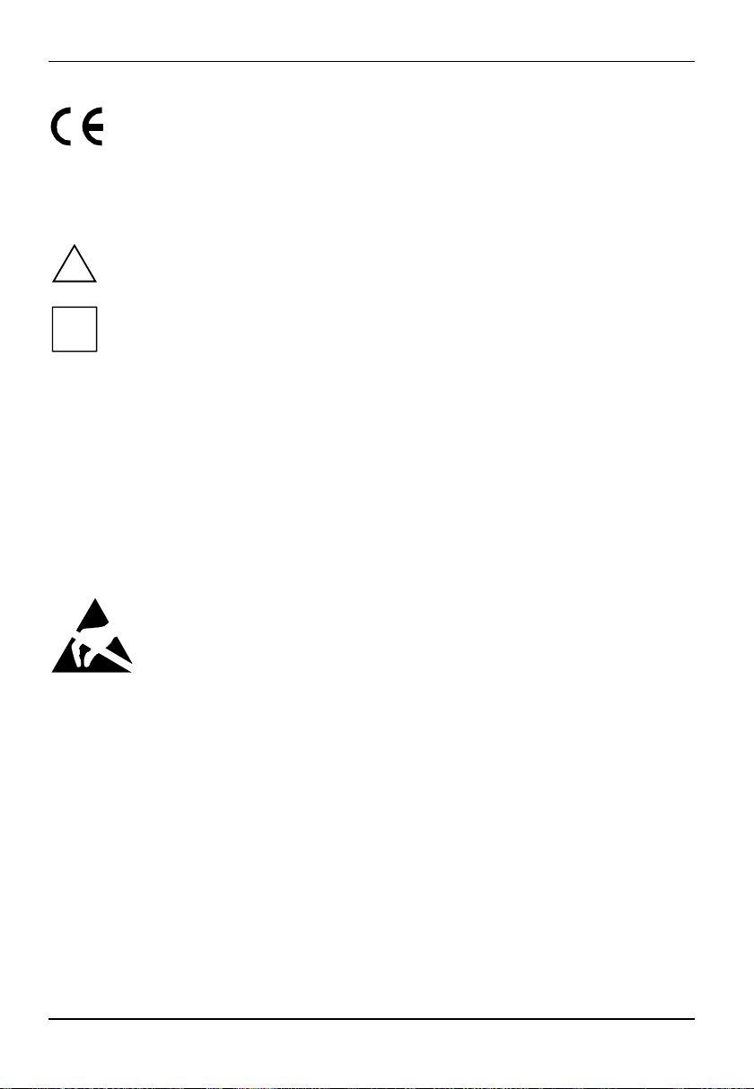
Installing a memory module
2
2
Ê Push the holders on each side of the memory slot outwards.
Ê Insert the memory module in the slot while folding the side holders up until the memory module
engages (2).
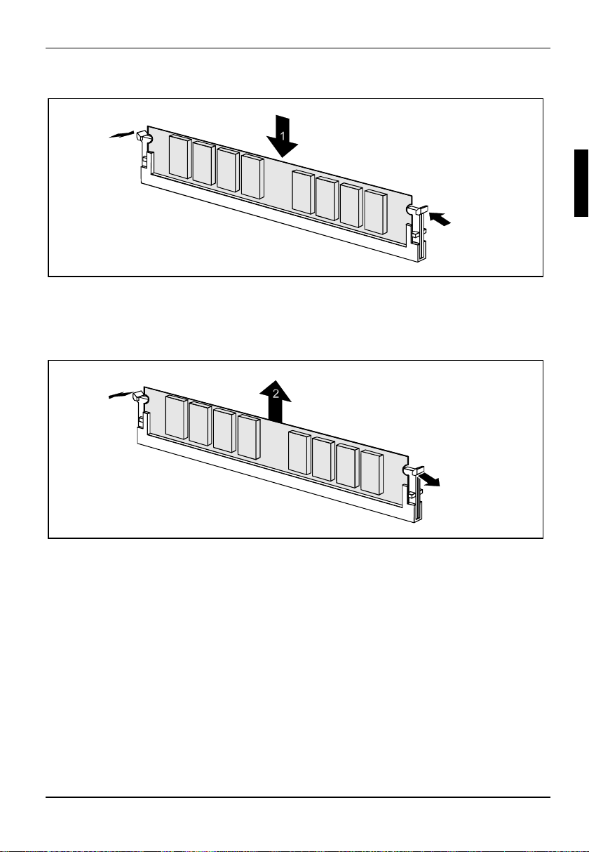
Removing a memory module
1
1
Ê Push the clips on the right and left of the memory slot outward (1).
Ê Pull the memory module out of the memory slot (2).
A26361-D1419-Z120-1-7419 English - 21
Page 30
Add-on modules
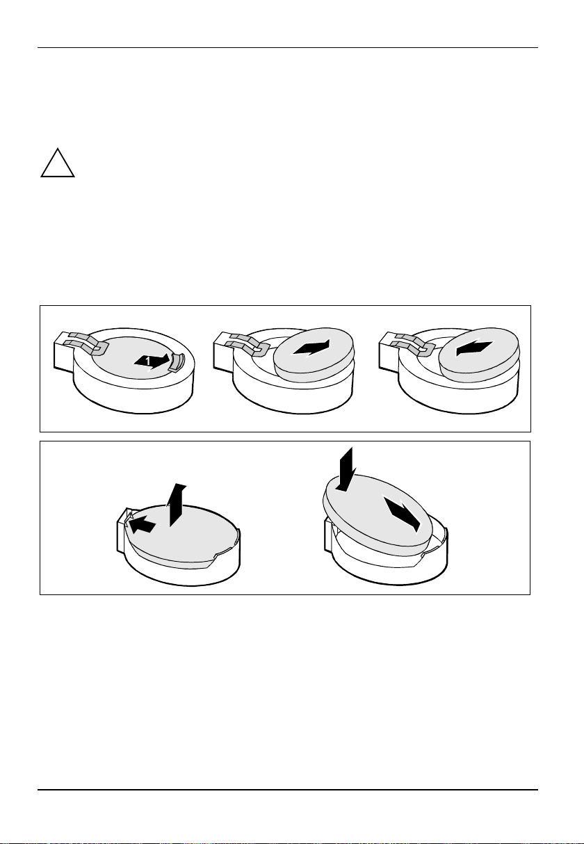
Replacing lithium battery
In order to permanently save the system information, a lithium battery is installed to provide the
CMOS-memory with a current. A corresponding error message notifies the user when the charge is
too low or the battery is empty. The lithium battery must then be replaced.
Incorrect replacement of the lithium battery may lead to a risk of explosion!
!
The lithium battery may be replaced only with an identical battery or with a type
recommended by the manufacturer.
Do not throw lithium batteries into the household waste. They must be disposed of in
accordance with local regulations concerning special waste.
Make sure that you insert the battery the right way round. The plus pole must be on the
top!
The lithium battery holder exists in different designs that function in the same way.
2
3
2
1
3
3
Ê Press the locking lug in the direction of the arrow (1); the battery jumps somewhat out of the
holder (2).
Ê Remove the battery (2).
Ê Insert a new lithium battery of the same type into the socket (3).
22 - English A26361-D1419-Z120-1-7419
Page 31

Glossary
Glossary
The technical terms and abbreviations given below represent only a selection of the full list of
common technical terms and abbreviations.
Not all technical terms and abbreviations listed here are valid for the described mainboard.
ACPI Advanced Configuration and
Power Management Interface
AC'97 Audio Codec '97 LAN Local Area Network
AGP Accelerated Graphics Port LSA LAN Desk Service Agent
AMR Audio Modem Riser MCH Memory Controller Hub
AOL Alert On LAN MMX MultiMedia eXtension
APM Advanced Power Management NMI Non Maskable Interrupt
ATA Advanced Technology
Attachment
BIOS Basic Input Output System PCI Peripheral Component
CAN Controller Area Network PXE Preboot eXecution Environment
CPU Central Processing Unit RAID Redundant Array of Inexpensive
CNR Communication Network Riser RAM Random Access Memory
C-RIMM Continuity Rambus Inline
Memory Module
DIMM Dual Inline Memory Module RDRAM Rambus Dynamic Random
ECC Error Correcting Code RIMM Rambus Inline Memory Module
EEPROM Electrical Erasable
Programmable Read Only
Memory
FDC Floppy disk controller RTC Real Time Clock
FIFO First-In First-Out SB Soundblaster
FSB Front Side Bus SDRAM Synchronous Dynamic Random
FWH Firmware Hub SGRAM Synchronous Graphic Random
GMCH Graphics and Memory Controller
Hub
GPA Graphics Performance
Accelerator
I2C Inter Integrated Circuit SMBus System Management Bus
IAPC Instantly Available Power
Managed Desktop PC Design
ICH I/O Controller Hub USB Universal Serial Bus
IDE Intelligent Drive Electronics VGA Video Graphic Adapter
IPMB Intelligent Platform Management
Bus
IPMI Intelligent Platform Management
Interface
IPSEC Internet Protocol Security
ISA Industrial Standard Architecture
P64H PCI64 Hub
Interconnect
Disks
RAMDAC Random Access Memory Digital
Analogue Converter
Access Memory
RSB Remote Service Board
Access Memory
Access Memory
SIMD Streaming Mode Instruction
(Single Instruction Multiple Data)
SVGA Super Video Graphic Adapter
WOL Wake On LAN
ZCR Zero Channel RAID
A26361-D1419-Z120-1-7419 English - 23
 Loading...